TiR3FT - Measuring instrument FLUKE - Free user manual and instructions
Find the device manual for free TiR3FT FLUKE in PDF.

| Product Type | Thermal Imaging Camera |
| Brand | Fluke |
| Model | TiR3FT |
| Detector Type | Uncooled Microbolometer |
| Spectral Range | 8 µm to 14 µm |
| Temperature Measurement Range | -20 °C to 600 °C |
| Accuracy | ±2 °C or 2% (whichever is greater) |
| Thermal Sensitivity (NETD) | ≤0.05 °C at 30 °C target temperature |
| Infrared Resolution | 320 x 240 pixels |
| Display | 3.5 inch LCD with 640 x 480 resolution |
| Image Frequency | 9 Hz or 30 Hz (model dependent) |
| Focus System | Manual and automatic |
| Emissivity Correction | Variable from 0.1 to 1.0 |
| Data Storage | SD card or internal memory |
| Battery Type | Rechargeable Lithium-Ion |
| Battery Life | Approximately 4 hours continuous use |
| Dimensions (H x W x D) | 27.2 cm x 15.9 cm x 9.7 cm |
| Weight (including battery) | 1.2 kg |
| Operating Temperature | -10 °C to 50 °C |
| IP Rating | IP54 (dust and splash resistant) |
| Laser Designator | Class 2 laser for target indication |
| Warranty | 2 years (standard), extended available |
Frequently Asked Questions - TiR3FT FLUKE
User questions about TiR3FT FLUKE
0 question about this device. Answer the ones you know or ask your own.
Ask a new question about this device
Download the instructions for your Measuring instrument in PDF format for free! Find your manual TiR3FT - FLUKE and take your electronic device back in hand. On this page are published all the documents necessary for the use of your device. TiR3FT by FLUKE.
USER MANUAL TiR3FT FLUKE
TiR2,TiR3,TiR4,Ti40,Ti45,Ti50,Ti55
IR FlexCam Thermal Imagers
Users Manual
January 2007, Rev.2, 5/09
©2007, 2009 Fluke Corporation. All rights reserved.
Specifications subject to change without notice.
All product names are trademarks of their respective companies.
LIMITED WARRANTY AND LIMITATION OF LIABILITY
Each Fluke product is warranted to be free from defects in material and workmanship under normal use and service. The warranty period is two years and begins on the date of shipment. Parts, product repairs, and services are warranted for 90 days. This warranty extends only to the original buyer or end-user customer of a Fluke authorized reseller, and does not apply to fuses, disposable batteries, or to any product which, in Fluke's opinion, has been misused, altered, neglected, contaminated, or damaged by accident or abnormal conditions of operation or handling. Fluke warrants that software will operate substantially in accordance with its functional specifications for 90 days and that it has been properly recorded on non-defective media. Fluke does not warrant that software will be error free or operate without interruption.
Fluke authorized resellers shall extend this warranty on new and unused products to end-user customers only but have no authority to extend a greater or different warranty on behalf of Fluke. Warranty support is available only if product is purchased through a Fluke authorized sales outlet or Buyer has paid the applicable international price. Fluke reserves the right to invoice Buyer for importation costs of repair/replacement parts when product purchased in one country is submitted for repair in another country.
Fluke's warranty obligation is limited, at Fluke's option, to refund of the purchase price, free of charge repair, or replacement of a defective product which is returned to a Fluke authorized service center within the warranty period.
To obtain warranty service, contact your nearest Fluke authorized service center to obtain return authorization information, then send the product to that service center, with a description of the difficulty, postage and insurance prepaid (FOB Destination). Fluke assumes no risk for damage in transit. Following warranty repair, the product will be returned to Buyer, transportation prepaid (FOB Destination). If Fluke determines that failure was caused by neglect, misuse, contamination, alteration, accident, or abnormal condition of operation or handling, including overvoltage failures caused by use outside the product's specified rating, or normal wear and tear of mechanical components, Fluke will provide an estimate of repair costs and obtain authorization before commencing the work. Following repair, the product will be returned to the Buyer transportation prepaid and the Buyer will be billed for the repair and return transportation charges (FOB Shipping Point).
THIS WARRANTY IS BUYER'S SOLE AND EXCLUSIVE REMEDY AND IS IN LIEU OF ALL OTHER WARRANTIES, EXPRESS OR IMPLIED, INCLUDING BUT NOT LIMITED TO ANY IMPLIED WARRANTY OF MERCHANTABILITY OR FITNESS FOR A PARTICULAR PURPOSE. FLUKE SHALL NOT BE LIABLE FOR ANY SPECIAL, INDIRECT, INCIDENTAL OR CONSEQUENTIAL DAMAGES OR LOSSES, INCLUDING LOSS OF DATA, ARISING FROM ANY CAUSE OR THEORY.
Since some countries or states do not allow limitation of the term of an implied warranty, or exclusion or limitation of incidental or consequential damages, the limitations and exclusions of this warranty may not apply to every buyer. If any provision of this Warranty is held invalid or unenforceable by a court or other decision-maker of competent jurisdiction, such holding will not affect the validity or enforceability of any other provision.
Fluke Corporation
P.O. Box 9090
Everett, WA 98206-9090
U.S.A.
Fluke Europe B.V.
P.O. Box 1186
5602 BD Eindhoven
The Netherlands
Table of Contents
Chapter
Title
1 Introduction ...... 1-1
Introduction 1-1
Contacting Fluke.... 1-2
Safety Information.... 1-2
Standard Accessories 1-4
Charge and Insert Battery 1-6
Power Camera On.... 1-7
Insert Memory Card.... 1-8
Focus.... 1-8
Set Temperature Level and Span 1-9
Set IR-Fusion® Blend Level.... 1-9
Capturing an Image.... 1-10
SmartView Software for Your PC 1-11
2 Camera Overview 2-1
Introduction 2-1
Camera Parts.... 2-2
Camera Display Screen.... 2-6
Programming Function Buttons.... 2-10
Using Display Screen Menus.... 2-12
Inserting and Removing Memory Card.... 2-13
3 Basic Operation.... 3-1
Acquiring and Reviewing Images.... 3-1
Scan Target.... 3-1
Pause/Save Image 3-1
View Saved Image 3-2
Delete Saved Image 3-2
Electronic Zoom 3-3
Saved Image Information.... 3-4
4 Analyzing and Enhancing Images 4-1
Setting Emissivity and Background Temperature.... 4-1
Fixed Image Function 4-2
Changing Color Palettes 4-2
Setting Temperature Level and Span.... 4-3
Manual Level and Span 4-3
Automatic Level and Span 4-4
Arbitrary Fixed Temperature Level and Span 4-4
Using Palette Saturation Colors.... 4-5
Using Display Screen Temperature Markers.... 4-7
Annotations 4-9
Adding Annotations to Saved Images 4-9
Creating Annotations Lists in SmartView 4-12
5 Visible Light Camera Module (VLCM) 5-1
Enabling/Disabling Visible Light Camera Module 5-1
Using Image Alignment 5-1
Focusing.... 5-2
Adjusting IR-VL IR-Fusion® Blend Level 5-3
Using Full Screen or Picture-in-Picture View 5-4
Adjusting Brightness and Color Controls.... 5-4
Using Torch Control.... 5-5
Using Visible Light Flash.... 5-5
Recording Visible Light Images.... 5-6
Using Laser Pointer 5-7
Using Thumbnail Browser 5-7
Using Color Alarms 5-8
Using Menu to Adjust Color Alarm Ranges.... 5-8
Using Palette Bar to Adjust Color Alarm Ranges 5-9
6 Camera Setup.... 6-1
Adjusting Display Screen Brightness 6-1
Hiding Display Screen Task Bar 6-2
Hiding Display Screen Color Palette.... 6-2
Setting Temperature Units.... 6-3
Setting Temperature Calibration Range 6-3
Changing Lens Selection.... 6-3
Setting Date and Time.... 6-4
Changing the Language.... 6-6
Saving and Reloading Camera Settings.... 6-6
Naming Image Files 6-7
Changing Image File Name Prefix 6-8
Resetting Image File Name Sequence Number 6-9
Selecting Video Output Options.... 6-9
7 Advanced Operation.... 7-1
Enhancing the Image 7-1
Using Auto Capture.... 7-1
Using User-Defined Display Screen Temperature Markers 7-4
Using Internal Recalibration....7-7
8 Camera Care.... 8-1
Cleaning the IR Lens, VLCM, Display Screen, and Body 8-1
Using Other Lenses 8-2
Viewing Camera and Battery Information....8-2
Charging the Batteries 8-3
Recalibrating the Batteries 8-4
Conserving Battery Power 8-5
Appendices
A Glossary.... A-1
B Troubleshooting...... B-1
C Emissivity Values.... C-1
D Camera Specifications and Dimensions...... D-1
E Resources and References.... E-1
F Camera Default Settings F-1
List of Tables
Table Title Page
1-1. Symbols 1-4
1-2. Standard Accessories 1-6
2-1. Camera Parts--Descriptions 2-6
2-2. Display Screen--Descriptions 2-1
2-3. Programmable Functions 2-14
4-1. Standard Saturation Colors 4-8
8-1. Remaining Battery Charge Indicators 8-3
8-2. Battery Charging Status 8-4
List of Figures
Figure Title Page
1-1. Standard Accessories.... 1-5
1-2. Inserting the Battery.... 1-7
1-3. Turning the Power On and Off 1-7
1-4. Inserting a Memory Card.... 1-8
1-5. Focusing the Camera 1-8
1-6. Setting the Level and Span 1-9
1-7. Setting the IR-Fusion® Blend Level.... 1-10
1-8. Capturing an Image.... 1-11
2-1. Camera Back View 2-3
2-2. Camera Front and Top View.... 2-3
2-3. Camera Bottom View 2-3
2-4. Camera Display Screen--Example 1 2-6
2-5. Camera Display Screen--Example 2.... 2-7
2-6. Camera Display Screen--Example 3.... 2-7
2-7. Inserting and Removing a Memory Card.... 2-13
5-1. Aligning the 20-mm Lens 5-2
Chapter 1 Introduction
Introduction
Thank you for choosing the IR FlexCam ^® portable infrared camera (referred to hereafter as the “Camera”). This award-winning Camera offers some of the most advanced, yet most intuitive, fully-radiometric solutions available. The visible light camera module (VLCM) and IR-Fusion ^® functions make it easier than ever to manage and analyze images captured with this system and improve reporting abilities. The unique control image and IR-Fusion ^® technology enables you to combine visible light images—like a normal digital camera—and infrared images together to create a single image with greatly enhanced detail. This is especially helpful in low contrast scenes where the temperature differential is minimal and the infrared image appears to be all one color.
The IR FlexCam is available in 7 models. The TiR2, Ti40 and Ti45 cameras use a detector with 160 x 120 resolution. The TIR3, TiR4, Ti50 and Ti55 cameras use a detector with 320 x 240 resolution. Refer to Appendix D for specific features available on your camera.
Your Camera is powerful and easy to use in a wide range of applications including:
Predictive Maintenance
• Electrical Systems—Identify circuit overloads before they happen.
- Mechanical Systems—Reduce downtime and prevent failures.
- Utilities—Monitor substations, transmission lines, etc. efficiently and accurately.
Building Science
• Roofing—Detect and isolate water saturation quickly and efficiently.
- Building Envelope—Perform commercial and residential infrared energy audits.
- Moisture Detection—Get to the source of moisture and mold growth.
- Restoration—Evaluate remediation work to make sure area is completely dry.
Research and Development
- Visualize and quantify generated heat patterns to improve products and the processes used to create them.
Process Monitoring
• Monitor and observe temperatures of processes in real-time.
To quickly take advantage of the many functions your Camera offers, we recommend that you carefully read this manual. It is designed to familiarize you with the most important aspects of your camera and guide
you in using the features of this system. This manual provides instruction on how to capture high quality images; however, thermography is a sophisticated field often requiring special training that is not covered in this manual. If you would like information on thermography training, contact Fluke Corporation.
Contacting Fluke
To contact Fluke, call:
1-800-760-4523 in USA
1-800-363-5853 in Canada
+31-402-675-200 in Europe
+81-3-3434-0181 in Japan
+65-738-5655 in Singapore
+1-425-446-6888 from anywhere in the world
Or, visit Fluke's website at www.fluke.com.
To register your product, visit http://register.fluke.com.
To view, print, or download the latest manual supplement, visit http://us.fluke.com/usen/support/manuals.
Safety Information
Use your Camera only as specified in this manual.
A ⚠ Warning identifies hazardous conditions and actions that could cause bodily harm or death.
A △ Caution identifies conditions and actions that could damage the camera or cause permanent loss of data.
Caution
- To avoid damaging your Camera, treat it with care as you would any type of precision equipment.
- Your infrared camera is a precision instrument that uses a sensitive infrared (IR) detector. Pointing your camera towards highly-intense energy sources—including devices that emit laser radiation and reflections from these devices—may adversely affect camera accuracy and may harm or permanently damage your camera’s IR detector.
- Your camera was calibrated prior to shipping. We recommend that you have your camera checked for proper calibration every two years. Some ISO 9000 programs require more frequent checks for certification. Contact Fluke for details.
- Your camera requires three minutes to warm up before accurate measurements are available.
Warning
- Your camera contains a Class 2 laser pointer. See diagram in Appendix B for laser aperture location.
- To avoid eye damage, do not point laser directly at eye or indirectly off reflective surfaces.
- Use of controls or adjustments or performance or procedures other than those specified herein may result in hazardous laser radiation exposure.
- Do not use camera in a manner not specified in this manual or the protection provided by the equipment may be impaired.
See Table 1-1 for a list of symbols used in this manual.
Table 1-1. Symbols
| Symbol | Description | Symbol | Description |
 | Class 2 laser pointer Hg | Contains Mercury. Dispose Properly. | |
 | On Off Symbol  | Important information. See manual. | |
 | Conforms to requirements of European Union and European Free Trade Association. | ||
 | Do not dispose of this product as unsorted municipal waste. Go to Fluke's website for recycling information. | ||
 | This camera contains a lithium battery. Do not mix with the solid waste stream. Spent batteries should be disposed of by a qualified recycler or hazardous materials handler per local regulations. Contact your authorized Fluke Service Center for recycling information. | ||
Standard Accessories
If any of the standard accessories shown in Figure 1-1 and described in Table 1-2 are missing or damaged, contact a Fluke customer service representative.
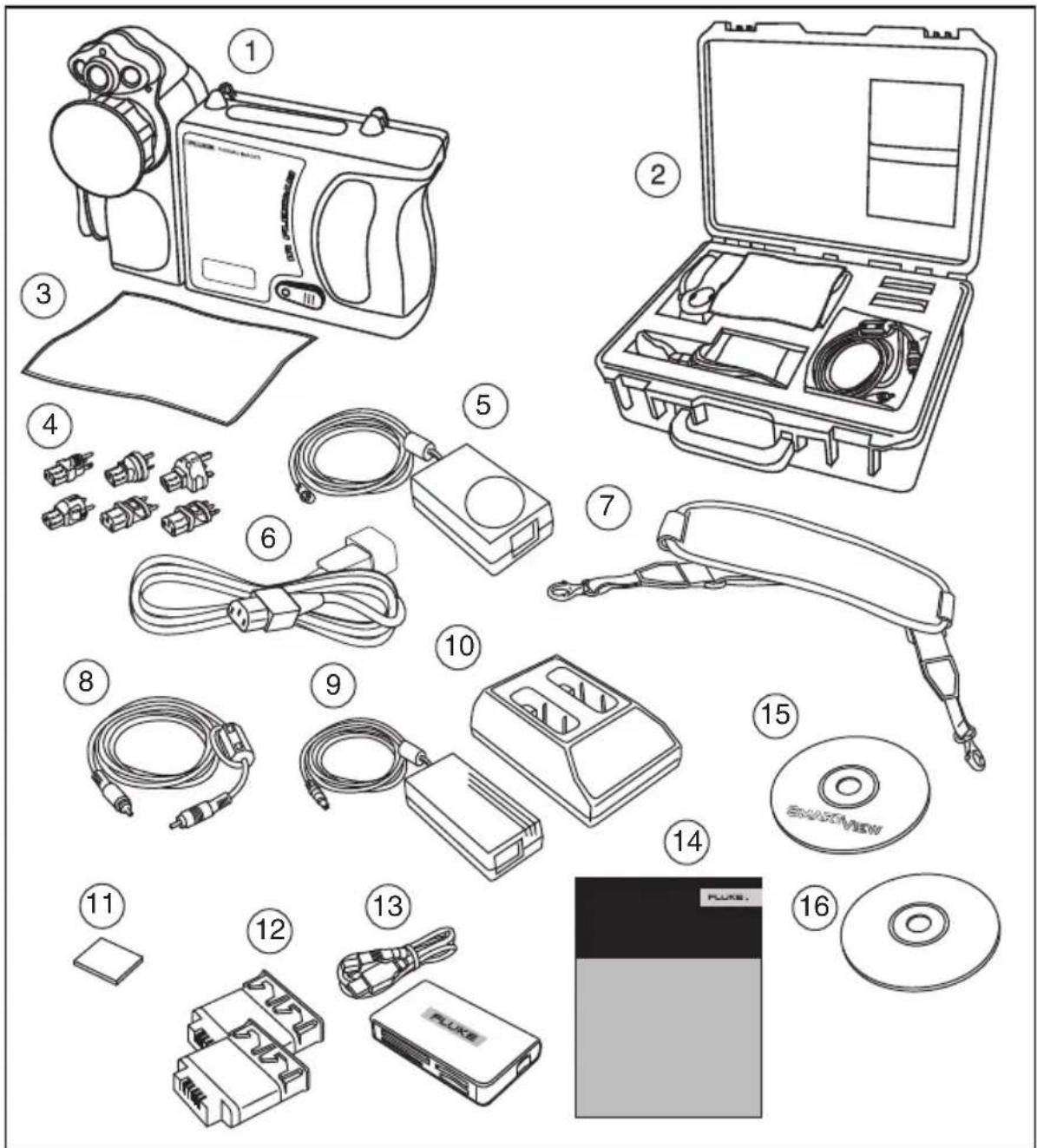
text_image
Exploded view diagram of a device assembly with numbered parts including camera, battery pack, and CD.eii001.eps
Figure 1-1. Standard Accessories
Table 1-2. Standard Accessories
| Number | Description |
| 1 Portable Infrared Camera with Lens Cap | |
| 2 Camera Carrying Case | |
| 3 LCD Cleaning Cloth | |
| 4 AC adapters (2) or equivalent | |
| 5 Auxiliary AC Power Supply (TiR2, TiR4, Ti45 and Ti55 only) or equivalent | |
| 6 AC Patch Cord or equivalent | |
| 7 Neck Strap | |
| 8 Video Cable | |
| 9 AC Power Supply | |
| 10 Battery Charger | |
| 11 Compact Flash Memory Card | |
| 12 Two Rechargeable Batteries | |
| 13 Multifunction Memory Card Reader with USB Adapter | |
| 14 Getting Started Guide | |
| 15 SmartView® Software CD (includes SmartView Users Manual) | |
| 16 FlexCam Documentation CD (Users Manuals) | |
Charge and Insert Battery
Charge the batteries for 3 hours before use. Use only the rechargeable batteries supplied. A battery is fully charged when the green LED light on the charger remains solid.
Insert the charged battery into the slot on the bottom of the camera as shown in Figure 1-2.
Note
You may use the auxiliary AC power supply to connect the camera to a working AC outlet until at least one of the batteries is charged.
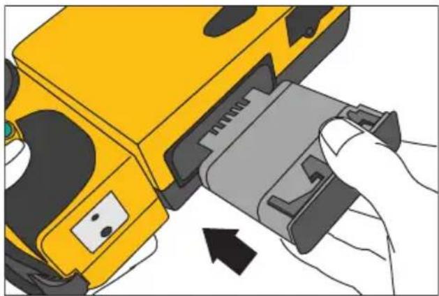
natural_image
Illustration of a yellow handheld device being inserted into a gray plastic clip, with no visible text or symbols.eii002.eps
Figure 1-2. Inserting the Battery
Power Camera On
With a charged battery inserted, or AC power supply connected, press ⏻ as shown in Figure 1-3. ⏻ lights up green, and the start-up screen appears after approximately 10 seconds.
Note
After powering on your camera, the camera requires a boot up and warm up period of approximately 30 seconds in order to maintain a crisp, clear, real-time image. Three minutes after powering on the camera, the temperature measurement accuracy will be within the specification requirements.
Note
Because of the thermal mass for the optional 54 mm lens, a warm up period of 30 minutes is necessary for optimum temperature measurement.

text_image
On/Off F2 F3eii003.eps
Figure 1-3. Turning the Power On and Off
Insert Memory Card
- Pull cover up and rotate as shown in Figure 1-4.
- Insert the Compact Flash memory card into the slot with the card's connection end pointed at the camera and the label with MB size facing the back of the camera.
- Look for the "Compact Flash Card inserted" message on the camera display screen.
- Close the cover.

natural_image
Close-up of a mechanical device with a yellow handle and black lever, showing a downward arrow indicating a process (no text or symbols present)Figure 1-4. Inserting a Memory Card
eii004.eps
Focus
Remove the lens cap, point the lens at the target, and manually rotate the lens with your finger, as shown in Figure 1-5, until the image is in focus.

natural_image
Yellow FLUKE THERM camera with rotating lens and directional arrow (no text or symbols on device body)Figure 1-5. Focusing the Camera
eii005.eps
Set Temperature Level and Span
- Press ③ as shown in Figure 1-6 to automatically set the camera's temperature level and span.
- Press ③ again as needed to properly scale the image.
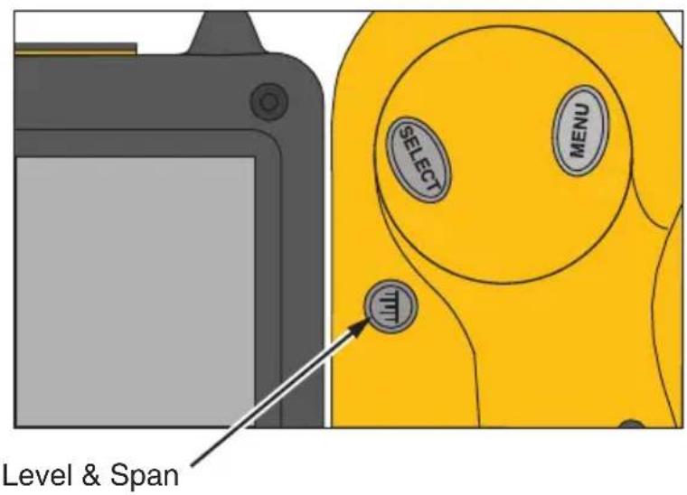
text_image
Level & Span SELECT MENUFigure 1-6. Setting the Level and Span
eii006.eps
Set IR-Fusion® Blend Level
Note
IR-Fusion® blending is disabled with optional 10 and 54-mm lenses.
- Press and hold Ⓤ until the IR-Fusion® blend level dialog box appears on the display screen.
- While continuing to press Ⓗ, use the mouse controller shown in Figure 1-7 to slide the IR-Fusion® blend level bar in the dialog box to the desired setting.
- Tap the trigger button ( ) to retain settings.

text_image
Mouse Controller F1 F2 F3 Level & Span SELECTeii007.eps
Figure 1-7. Setting the IR-Fusion® Blend Level
Capturing an Image
- Tap once (shown in Figure 1-8) to pause the live image.
- Review the image and camera settings.
- Press and hold Ⓞ for 2 seconds to capture (save) the image. The image file name appears in the upper left-hand corner of the display screen indicating the image is saved on the memory card.
Note
The memory card must be inserted into the camera to save and store images.
- Tap to return to scan target mode.
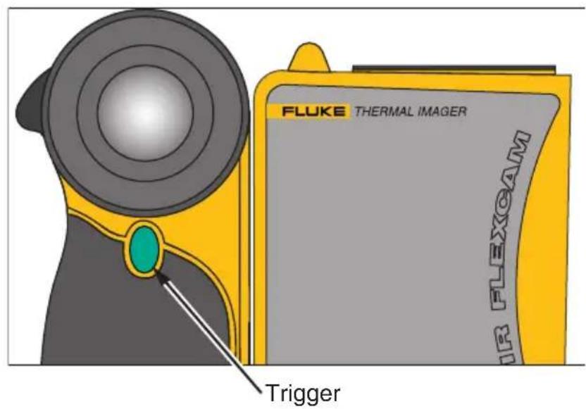
text_image
FLUKE THERMAL IMAGER IR FLEXOAM TriggerFigure 1-8. Capturing an Image
eii008.eps
SmartView Software for Your PC
Your system includes a CD containing SmartView® software that you install on your personal computer. SmartView, together with your Camera, enables you to:
• Transfer thermographic images to a computer and efficiently manage them
- Optimize and analyze your infrared and visible light control images
• Create and print detailed, professional reports containing important image data
SmartView image analysis software is compatible with any personal computer running Microsoft Windows 2000/XP/Vista (32 bit). This software is provided on the SmartView CD-ROM disk included with your camera.
To install SmartView software on your computer:
- Start your computer and close any open applications.
-
Insert the CD-ROM disk containing the SmartView software in the CD-ROM drive.
If the SmartView CD does not start automatically, use Windows explorer to locate the file named "setup.exe" on the CD-ROM. Start the CD by double-clicking the setup.exe file. -
Follow the on-screen instructions to complete the installation.
Chapter 2
Camera Overview
Introduction
Your Camera is a compact, lightweight system that offers a generous five-inch display module you can position for optimal viewing. You can also rotate the lens module to easily capture target images on ceilings, hidden above high objects, under low obstacles, or in other hard-to-reach places. In addition, you can position the camera for comfortable desktop image analysis and can mount the system on a standard tripod to continuously monitor a single location.
Although your Camera is a sophisticated imaging system with many advanced functions, it is easy to operate using buttons, mouse-controlled menu options, or a combination of both.
The visible light camera module (VLCM) adds a 1.3 mega pixel visible light sensor that improves your ability to identify and analyze thermal anomalies and to provide visible light control images for your reports.
Camera Parts
Camera features and controls are shown in Figures 2-1, 2-2, and 2-3 and described in Table 2-1.
text_image
Fluke use only 1 2 3 4 5 6 7 8 9 10 11 12eii009.eps
Figure 2-1. Camera Back View
text_image
FLUKE THERMAL IMAGER IR FLEXOAM 21 19 16 15 14 13 20 17 18Figure 2-2. Camera Front and Top View
eii010.eps
text_image
Diagram of a yellow device with labeled parts 22 and 23, showing internal components and a button.Figure 2-3. Camera Bottom View
eii011.eps
Table 2-1. Camera Parts – Descriptions
| Item | Description |
| 1 | Mouse controller – Used to control the pointer position in images and text menus. |
| 2 | SELECT select button – Performs mouse click, or “enter” function, for the pointer. |
| 3 | MENU Menu button – Used to access display screen menus. Note: Tap once and a popup menu appears. |
| 4 | F1 Programmable function button – Can be programmed to perform different menu functions, see Programming Function Buttons later in this Chapter. |
| 5 | F2 Programmable function button – Can be programmed to perform different menu functions, see Programming Function Buttons later in this Chapter. |
| 6 | F3 Programmable function button – Can be programmed to perform different menu functions, see Programming Function Buttons later in this Chapter. |
| 7 | Power on or off button – Used to power camera on and off and to place the camera in a low-power standby mode to conserve battery power.Solid green = power is on; Blinking green = standby mode enabled. |
| 8 | Auxiliary power port – Connection port for AC to DC power adapter. |
| 9 | Reset – Hidden switch to reset camera. Can be accessed with a paper clip. See, “Appendix B – Troubleshooting”. |
| 10 | Battery latch – Used to remove battery. |
| 11 | Liquid Crystal Display (LCD) screen – Sunlight-readable color display for viewing images and accessing camera menu functions. |
| 12 | LEVEL & SPAN button – Used to rescale the color palette to the maximum and minimum temperatures in current image and to adjust IR IR-Fusion® level. |
| 13 | Infrared lens – Germanium lens with manual focus. |
| 14 | Torch/Flash – When enabled, the torch illuminates darker work areas. When enabled, the flash lights the target object during image capture for better-quality visible light images. The torch and flash can be enabled at the same time. |
| 15 | Visible light lens – Captures visible light control images. |
| 16 | Laser – Used to point out the object you are aiming the camera towards. |
| 17 | Trigger button – Used to pause and/or save an image frame. Also used to accept a setting change (i.e., OK click), close a menu page, and to return to scan target mode. |
| 18 | Video port – RCA video jack used to connect camera to a TV or video monitor. |
| 19 | CompactFlash memory card slot – Ejection button and slot for CompactFlash memory card. |
| 20 | Hand strap – Adjustable strap for added stability when capturing images. |
| 21 | Neck strap mount – Pins for attaching neck and/or shoulder strap. |
| 22 | Tripod mount – Standard 1/4-20 threaded hole for mounting camera on tripod. |
| 23 | Battery – Fluke 7-volt lithium-ion battery for primary power. |
Camera Display Screen
Display screen features and controls are shown in Figures 2-4, 2-5, and 2-6 and described in Table 2-2.

other
| Component | Value | | --------- | ----- | | Max | 76.3 | | Avg | 74.5 | | Min | 73.4 | | IR20050912_0003 | 74.3 | | Max | 75.2 | | 101.0 | 101.0 | | 92.0 | 92.0 | | 83.0 | 83.0 | | 0.95 | 0.95 | | 68.0 | 68.0 | | 09-12-05 | 09-12-05 | | 16:07:15 | 16:07:15 | | °F | °F | | ① | ① | | ② | ② | | ③ | ③ | | ④ | ④ | | ⑤ | ⑤ | | ⑥ | ⑥ | | ⑦ | ⑦ | | ⑧ | ⑧ | | ⑨ | ⑨ | | ⑩ | ⑩ | | ⑪ | ⑪ | | ⑫ | ⑫ | | ⑬ | ⑬ | | ⑭ | ⑭ | | ⑮ | ⑮ | | ⑯ | ⑯ | | ⑰ | ⑰ |Figure 2-4. Camera Display Screen – Example 1
eii012.eps
text_image
* IR20050912_5046 35.3 A0:19.0/19.0/19.0 35.3 P0:20.0 16 17 15 18eii013.eps
Figure 2-5. Camera Display Screen – Example 2
text_image
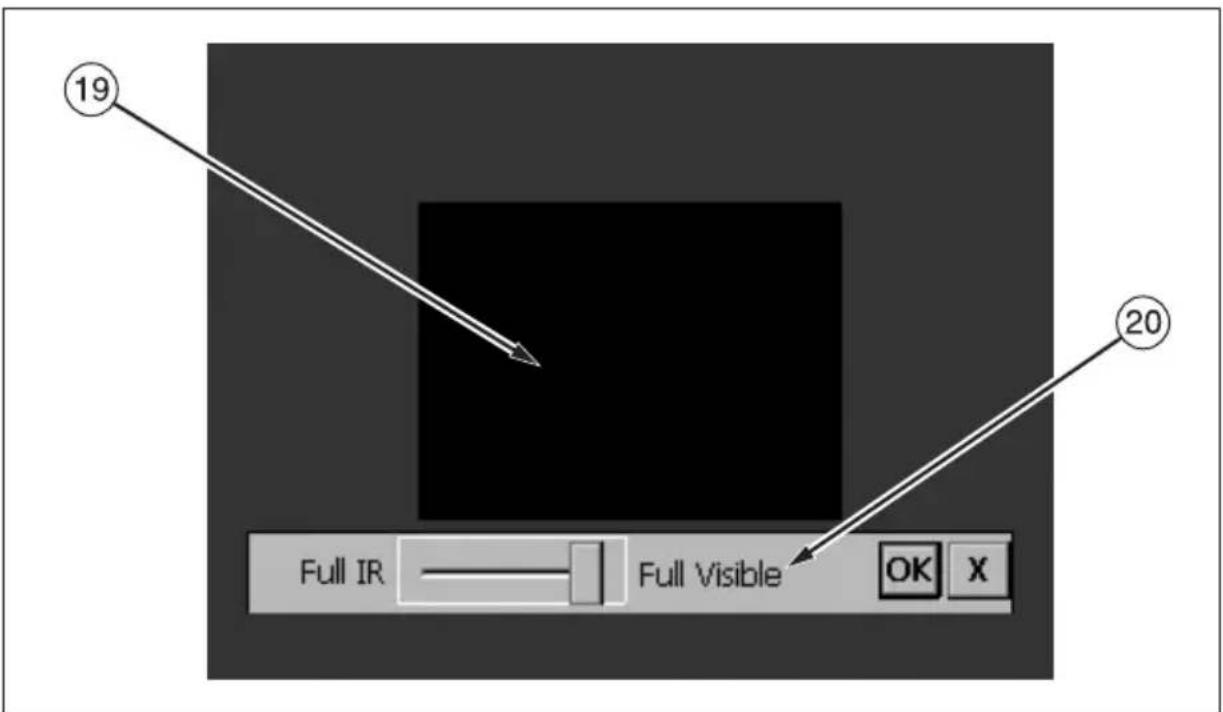
19 Full IR Full Visible OK X 20eii014.eps
Figure 2-6. Camera Display Screen – Example 3
Table 2-2. Display Screen – Descriptions
| Item | Description |
| 1 | Color palette – Palette used in displayed image; click to change color palette options. |
| 2 | Level and Span – Maximum, center, and minimum temperatures of the color palette. Click temperatures to change limits of a fixed temperature range. |
| 3 | Center point temperature – Average temperature of the center-most group of four pixels. |
| 4 | Mouse pointer and temperature – Temperature at the location of the mouse pointer. |
| 5 | Image name – Image name created from an assignable prefix, the date image was taken, and a sequencing number. Appears only when viewing saved images. |
| 6 | Browse image arrows – Appear when Browse Image function is enabled. Click to scroll to the next or the previous image. |
| 7 | Programmable button icons – Icons for the three programmable buttons: F1, F2, and F3. Click icon to change button function. |
| 8 | Emissivity—Used by camera to calculate target temperatures and location; click number to change the emissivity value. |
| 9 | Background temperature – Used by camera to calculate target temperatures and location; click number to change background temperature. |
| 10 | Date – Current date; click to change date. |
| 11 | Time – Current 24-hour time; click to change time. |
| 12 | Temperature units – Used to display camera temperature units; click to change the temperature units. |
| 13 | Power source – Icon indicating either AC power or battery level; click to identify remaining time available from current battery charge. |
| 14 | Center box with temperatures – Center 50 by 50 pixel box with the maximum, average, and minimum temperatures in the box (when enabled). |
| 15 | Hot cursor temperature – Temperature and location of the hottest temperature in the image; always in red (when enabled). |
| 16 | Cold cursor temperature – Temperature and location of the coldest temperature in the image; always in blue (when enabled). |
| 17 | Analysis point – Temperature of marker point in the image. You can add up to three marker points (when enabled). |
| 18 | Analysis area – Min., avg., and max. temperatures of the marker area in the image. You can add up to three marker areas (when enabled). |
| 19 | Picture-in-picture (PIP) – The fused, or blended, infrared/visible light image appears in the center quarter of the display screen and the visible light image appears in the rest of the display screen (when enabled). |
| 20 | IR-Fusion® blend level dialog box – Used to change the IR-Fusion® blend level from full infrared (IR) to full visible light (VL) or some combination in between. Disabled when using optional 10 and 54-mm lenses. |
Programming Function Buttons
You can assign any of the functions described in Table 2-3 to any one of three programmable buttons: F1, F2, F3 (see Appendix F for a list of default settings). See programming instructions on the next page.
Table 2-3. Programmable Functions
| Item | Description |
 | Centerpoint/Centerbox – Used to cycle the centerpoint on, then centerpoint and centerbox on, then the centerpoint and centerbox both off. |
 | Zoom – Used to quickly cycle between 2x, 4x, 8x zoom, and normal display settings (zoom options vary by camera model; see Appendix D). |
 | Brightness – Used to quickly cycle through the display screen brightness settings: “Dim,” “Normal,” and “Bright.” Each time you press the function button, the next setting takes affect. |
 | Annotation – Used to quickly access the image annotation editor (available on TiR2, TiR4,Ti45 and Ti55 models only). |
 | Browse Images – Used to immediately recall the last saved or last viewed image. |
 | Browse Thumbnails – Used to quickly browse thumbnails of images stored on the CompactFlash memory card. |
 | Palette Visible – Used to quickly cycle the color palette bar on or off the display screen. |
 | Marker Toolbar Visible – Used to show or hide the marker toolbar for adding extra visible marker points or areas to the image and displaying temperatures near them. |
  | Torch – Used to quickly switch the LED light on or off. When on, light shines continuously to brighten up dark work areas; light automatically times out after 60 seconds.Laser – Used to help you correlate what is on the camera display screen with what you are looking at. The laser spot is visible in the control image and can be a valuable reference point for later image review. |
 | Start Sequence – Used to quickly start the Auto Capture sequence. (Auto Capture is available on TiR2, TiR4, Ti45 and Ti55 models only.) |
 | Stop Sequence – Used to quickly stop the Auto Capture image capture sequence. (Auto Capture is available on TiR2, TiR4, Ti45 and Ti55 models only.) |
 | Image Enhancement – Used to quickly cycle through the image enhancement settings: “Off,” “Normal,” “Medium,” and “High.” Each time you press the function button, the next setting takes affect. |
 | Picture-in-Picture – Used to quickly switch between full screen view and picture-in-picture view. |
 | Recalibrate – Used to manually trigger an internal calibration adjustment. |
To program buttons F1, F2, and/or F3:
- Use the mouse controller to position the pointer over the function icon on the display screen task bar (F1, F2, F3) you wish to program.
- Tap SELECT. A popup menu with list of programmable tasks appears.
- Position the pointer over the desired task and select.
- Repeat Steps 1-3.
Using Display Screen Menus
Your camera is user-friendly and easy to operate and mirrors the way you use a personal computer. With a mouse controller and select button, you can select task bar items on the camera display screen and access and navigate through on-screen menus. In many cases, you can perform the same task either of two ways: by clicking on a display screen task bar item and/or opening a display screen menu to reveal additional options.
To select task bar items:
- Use the mouse controller to position the pointer over the task bar item you wish to choose.
- Tap SELECT to select the desired item.
- Follow the steps indicated in the section of this manual that corresponds to the selected task bar item.
To use the display screen menu options:
-
Tap MENU. The first level popup menu appears:
-
Camera Info
- Model Features (including refresh rate, features supported, languages)
- Calibration Information (for example, lens type)
-
Revision (including OS build, DSP version, software version)
-
Camera Settings
- Browse Images
- Image Settings
- Annotate Image
- Start Sequence
-
Save Image
-
Use the mouse controller to position the pointer over the menu item you wish to choose.
-
Tap SELECT to select the desired menu item.
-
Use the mouse controller and SELECT to position the pointer and then select desired option from the tabs displayed.
- Use the mouse controller and button to select the functions you want within the tab.
- Tap to accept setting change and return to scan target mode.
Inserting and Removing Memory Card
Your Camera comes with a removable, reusable CompactFlash memory card capable of storing hundreds of images. Inserting and removing a memory card is shown in Figure 2-7.

natural_image
Close-up of a mechanical device with a lever and handle, showing a black arrow pointing to a component (no text or symbols visible)Figure 2-7. Inserting and Removing a Memory Card
eii004.eps
Note
The card must be inserted into the camera to save and store images. Use only SanDisk-brand CompactFlash memory cards with a 2003 or newer copyright date. Do not use other memory card brands.
Caution
To avoid loss of images in the event of a technical problem with either the Camera or the memory card, be sure to regularly transfer the images you save on the CompactFlash memory card to a computer hard drive and/or other back-up storage device (e.g., CD-R disc).
Caution
To avoid damaging the memory card or your camera, be sure to insert the card properly. The card can be inserted only one way; forcing it may damage your camera.
To insert a memory card:
-
Lift memory card slot cover.
-
Insert the SanDisk-brand CompactFlash memory card into the slot with the card's connection end pointed at the camera and the label with MB size facing the back of the camera.
Note
If the camera is powered on, the message, “Compact Flash Card inserted” is displayed.
To remove a memory card:
Note
Camera can be on or off when removing a memory card.
Caution
To prevent data loss or corruption, do not remove the memory card while saving an image.
- Lift memory card slot cover.
- Firmly press the memory card ejection button. The card partially slides out of the slot.
- Remove the memory card from the slot and close the cover.
Acquiring and Reviewing Images
Your Camera has three operating modes: scan target, pause/save, and view/delete images.
Scan Target
To scan target area of interest:
- Press ⏻ to power on the camera.
- Remove lens cap and point the lens at the target area.
- Focus and view the target area on the display screen.
- Tap ③ to set the camera's temperature level and span; tap ④ again as needed to quickly bring the target area into view.
- Move the camera or lens module as necessary to view various scenes.
Pause/Save Image
To pause and then save a target area image, follow the Scan Target procedure, then quickly tap the trigger ( ) button. The word “Paused” appears in the upper left corner of the display, and the live target area image is paused enabling you to analyze the image and determine if it is acceptable enough to save. If not, quickly tap again to return to scan target mode. If image is acceptable, you can save it for future reference.
To save an image for future reference, make sure CompactFlash memory card is inserted (see Chapter 2) and follow the procedures under Scan Target. When an area of interest is visible on the display screen, press and hold until the hour glass is displayed (approximately 2-3 seconds). The image is now saved and stored on the CompactFlash memory card. See “Naming Image File”s in Chapter 6.
The image name is displayed in the upper left corner of the display screen.
Tap to return to scan target mode.
View Saved Image
To view images saved on the memory card:
- Make sure memory card is inserted (see Chapter 2), then tap MENU.
- Use the mouse controller to position the pointer over Browse Images on the popup menu and tap SELECT.
- Position the pointer over the thumbnail view of the image you want to open, and double-click SELECT to open.
If the image you want is not on the first page, position the pointer over the right/left arrows at the bottom of the display screen and tap SELECT as many times as needed to scroll to the page you want, then follow Steps 3-4. - Tap Ⓞ to close the open image and return to scan target mode.
- Tap to accept setting change and return to scan target mode.
Delete Saved Image
To delete images saved on the memory card one at a time:
- Make sure memory card is inserted (see Chapter 2), then tap MENU.
- Use the mouse controller to position the pointer over Browse Images on the popup menu and tap SELECT.
- Position the pointer over the thumbnail view of the image you want to delete; the image is highlighted. Tap SELECT.
-
Position the pointer over the Delete button at the bottom of the display screen, tap SELECT. A new dialog box appears; select Yes to delete the image, No to keep the image, or Cancel to cancel the operation and return to the thumbnail screen.
If the image you want to delete is not on the first page, position the pointer over the right/left arrows at the bottom of the display screen and tap SELECT as many times as needed to scroll to the page you want, then follow Steps 3-5. -
Tap Ⓞ to close the thumbnail screen and return to scan target mode.
To delete all images saved on the memory card at the same time:
- Tap MENU.
- Use the mouse controller to position the pointer over Camera Settings on the popup menu.
- Tap SELECT.
- Position the pointer over the Files tab and tap SELECT.
- Position the pointer over Delete all images and tap SELECT.
- Select Yes (if you do not want to delete all images, select No or Cancel).
- Tap to return to scan target mode.
Electronic Zoom
From normal view, you can zoom to up to 8x (depending on the camera model; see camera specifications in Appendix D), which correspondingly enlarges the image.
To activate the electronic zoom feature:
- Tap MENU.
- Use the mouse controller to position the pointer over Image Settings in the popup menu and tap SELECT.
- Position the pointer over the Display tab and tap SELECT.
- Position the pointer over the Zoom Image up/down arrows and tap SELECT as needed to select zoom setting.
Saved Image Information
Opening the Info tab within the Image Settings menu window enables you to view a variety of information about a saved image, including: the name of the camera manufacturer, camera model number, lens focal length and f-number, lens model and serial number, and camera calibration date of the camera used to capture the image. This window/tab also contains the capture date and time for the selected saved image, as well as software versions used to manage the camera operation (OCA) and to perform image data processing (DSP).
To view a saved image's information:
- Make sure memory card is inserted (see Chapter 2), then tap MENU.
- Use the mouse controller to position the pointer over Browse Images on the popup menu and tap SELECT.
- Position the pointer over the thumbnail view of the image you want to open and double-click SELECT to open.
If the image you want is not on the first page, position the pointer over the right/left arrows at the bottom of the display screen and tap SELECT as many times as needed to scroll to the page you want, then follow Steps 3-7. - On the open image, tap MENU.
- Use the mouse controller to position the pointer over Image Settings on the popup menu and tap SELECT.
- Position the pointer over the Info tab and tap SELECT.
- Tap 0 to return to scan target mode.
Chapter 4
Analyzing and Enhancing Images
Setting Emissivity and Background Temperature
Setting your camera with correct emissivity and background temperature values is critical to making accurate temperature measurements.
Emissivity values on your camera and saved images are adjustable between 0.01 and 1.00 with increments of 0.01. This value, along with the background temperature and target radiation measured by the camera, is used to calculate target temperatures. Use the table in Appendix C, which lists the emissivity values of some common materials, as a guide to setting correct emissivity values.
To set the emissivity value for an image in the camera:
- Use the mouse controller to position the pointer over the emissivity value on the task bar and tap SELECT. (See Chapter 2 for emissivity value location on the task bar.)
- Use the up/down mouse action to raise or lower the value.
- Tap Ⓞ to accept setting change and return to the open image.
- Tap ● again to return to scan target mode.
To set the background temperature for an image in the camera:
- Use the mouse controller to position the pointer over the background temperature value on the task bar and tap SELECT. (See Chapter 2 for background temperature value location on the task bar.)
- Navigate up/down using the mouse controller to raise or lower the value.
- Tap ○ button to accept setting change and return to the open image.
- Tap ○ again to return to scan target mode.
Fixed Image Function
You can also set the emissivity and background temperature values by opening the Image Settings menu and clicking the Emissivity tab. From here, you can enable or disable the Fixed Image function. When this function is enabled, the palette minimum and maximum are adjusted as you change the emissivity, and the image appearance remains the same. When this mode is disabled, the palette minimum and maximum stay fixed, while the color rendering in the image changes accordingly.
To enable/disable the Fixed Image function:
- Tap MENU.
- Use the mouse controller to position the pointer over Image Settings on the popup menu and tap SELECT.
- Position the pointer over the Emissivity tab and tap SELECT.
- Position the pointer over the Fixed Image box; tap SELECT to add or remove a check mark. A check mark indicates the function is enabled.
- Tap ☐ to accept setting change and return to scan target mode.
Changing Color Palettes
Although all of your camera's color palettes can be used with any image, you may find that some color palettes work better than others for analyzing images depending on the situation.
You can change the color palette prior to capturing images and can change the color palette of images already saved on the memory card.
Two methods are available to change the color palette. Use the MOUSE controller to position the pointer over the color palette on the display screen and repeatedly press SELECT to cycle through the 8 color palette options.
Or, use the menu system as follows:
- Tap MENU.
- Use the mouse controller to position the pointer over Image Settings on the popup menu and tap SELECT.
-
Position the pointer over the Palette tab and tap SELECT.
-
Position the pointer over the Palette down arrow and tap SELECT to reveal the pull down menu.
- Position the pointer over desired color palette option and tap SELECT.
- Tap to accept setting change and return to scan target mode.
Setting Temperature Level and Span
The color palette is available to help you visualize the relation between temperature and color. Setting the span to the narrowest range possible provides the highest quality images.
When using the manual or automatic level and span function, if the center box function is enabled, the temperature updates are done based on the temperatures in the box, not the entire image. Using this feature, you can exclude an area in the image that is very hot or very cold but of little interest.
Manual Level and Span
When you press the LEVEL & SPAN button, your camera takes the current coldest and hottest temperatures from the scene and sets the palette range minimum and maximum limits so that everything in the scene is scaled between the minimum and maximum temperature if the target temperatures are within the camera's currently selected calibration temperature range. If the target temperatures are outside the currently selected calibration temperature range, the target is displayed in the saturation color for the current color palette (see Using Palette Saturation Colors later in this chapter).
Note
Be sure the temperature calibration range is set properly. See Setting the Temperature Calibration Range in Chapter 6). If you have enabled the center box marker (see Chapter 4), the color palette is adjusted based on the minimum and maximum temperatures in the center box, not those in the rest of the image.
To manually adjust the color palette temperature span, tap ☐ as needed. Be sure the “Manual” function is enabled (refer to the procedure under Automatic Level and Span).
Automatic Level and Span
When you enable the automatic level and span function, the color palette temperatures are regularly updated to the current maximum and minimum temperatures in the image at a time interval you set (from 1/4 second to 10 seconds).
To enable automatic adjustments of the color palette temperature span:
- Tap MENU.
- Use the mouse controller to position the pointer over Image Settings on the popup menu and tap SELECT.
- Position the pointer over the Palette tab and tap SELECT.
- Position the pointer over the Adjustment Interval down arrow, tap SELECT.
- Use the mouse controller to scroll to the interval you want, and tap SELECT. Select Manual, rather than an interval, to enable the Manual function.
- Tap ☐ to accept setting change and return to scan target mode.
Arbitrary Fixed Temperature Level and Span
This feature allows you to adjust the level and span “on the fly,” while scanning targets of special interest and creating high contrast in the temperature ranges of those targets.
Note
Be sure the temperature calibration range is set properly. See “Setting the Temperature Calibration Range” in Chapter 6. If you have enabled the center box marker (see Chapter 4), the color palette is adjusted based on the minimum and maximum temperatures in the center box, not those in the rest of the image.
To set the level and span to an arbitrary fixed temperature span:
- With the color palette showing on the display screen, highlight any one of the three palette temperature values (minimum, maximum, center point).
- If you highlight the minimum or maximum temperature, use the up/down mouse action to change palette range (span). The center point (level) temperature also changes accordingly.
- If you highlight the center point (level) temperature, use the up/down mouse action to move the center point temperature accordingly, while keeping the range (span) constant. Use the left/right mouse action to change the palette range (span), leaving the center point (level) unchanged.
- Tap 🔒 button to select to accept setting change and return to scan target mode.
You can also the level and span by using the menu system.
To set the level and span using the menu system
- Tap MENU.
- Use the mouse controller to position the pointer over Image Settings on the popup menu and tap SELECT.
- Position the pointer over the Palette tab and tap SELECT.
- Position the pointer over the Adjustment Interval down arrow and tap SELECT.
- Use the mouse controller to scroll to "Manual" and tap SELECT.
-
Position the pointer over either:
-
The Palette Range maximum temperature right/left arrows (repeat to change minimum temperature). or
-
The Palette Range center point temperature (repeat to change the span width temperature).
-
Use the mouse controller to scroll to the temperature settings you want.
-
Tap to select to accept setting change and return to scan target mode.
Using Palette Saturation Colors
The palette colors of your Camera are mapped to temperature measurements. When you set the color palette level and span, the full color range is used to display the image. This same temperature color mapping is maintained until you set the level and span again.
After setting the level and span, if the camera measures a temperature greater than the palette maximum temperature and/or a temperature lower than the palette minimum temperature, the image pixels with these temperature
extremes are displayed at the ends of the color palette. These pixels are called saturation colors. The standard saturation colors, described in Table 4-1, appear on the ends of the color palette bar and enable you to quickly see when temperatures are outside of the current range.
Table 4-1. Standard Saturation Colors
| Color Palette Standard | Standard High Temperature Saturation Color | Standard Low Temperature Saturation Color |
| Grayscale | Red | Blue |
| Grayscale Inverted Red | Blue | |
| Blue-red | White | Black |
| High-contrast | Blue-green | Dark |
| Hot Metal White Black | ||
| Ironbow | Green | Tan |
| Amber | Red | Blue |
| Amber Inverted Red Blue |
Brown
Note
With saturation colors OFF, the temperature extremes are displayed using the next-to-extreme colors in each palette.
To change, enable, or disable the saturation colors function:
- Tap MENU.
- Use the mouse controller to position the pointer over Image Settings on the popup menu and tap SELECT.
- Position the pointer over the Palette tab and tap SELECT.
- Position the pointer over the Saturation Colors down arrow, then tap SELECT.
- Use the mouse controller to scroll to the setting you want (Off, Standard, White/Black, Red/Blue), and tap SELECT.
- Tap ☐ to accept setting change and return to scan target mode.
Using Display Screen Temperature Markers
You can annotate images with various types of markers to help you interpret or analyze images. For example, you can highlight particular areas of interest in an image or highlight critical objects whose minimum, maximum, or average temperatures must be in a particular range.
Use the following basic marker options:
- Four standard spot temperatures: hot, cold, and center points each marked with a crosshair and the mouse pointer location, marked by the tip of the pointer.
• Maximum, minimum, and average temperatures for the center box.
You can enable these markers to appear on the display screen in scan target mode and/or on a saved image you open. With the mouse pointer marker enabled, you can move the pointer around the display screen to reveal the spot temperatures at any place on the image.
Note
To add advanced markers, see Chapter 7, User-Defined Temperature Markers.
Movable points and boxes and automatic hot and cold point detection functions are available on TiR2, TiR4, Ti45 and Ti55 models only.
The pointer may change orientation as it approaches the edge of the display screen.
"Unchecking" the mouse temperature removes the pointer temperature digits only; the pointer itself still appears on the display screen.
To enable/disable spot temperature marker functions from either scan target mode or from an open image:
- Tap MENU.
- Use the mouse controller to position the pointer over Image Settings on the popup menu and tap SELECT.
-
Position the pointer over the Display tab and tap SELECT.
-
Position pointer over one of the temperatures you want to appear in the image (Center Point, Center Box, Hot Cursor, Cold Cursor) and tap SELECT. A check mark indicates the function is enabled.
- Repeat Step 4 as needed to choose additional temperature reading options and/or to “unchecked” options you do not want to appear on the image. In scan target mode, you can also select Onscreen Logo. A check mark indicates the Fluke logo will appear on the display screen in scan target mode.
- Tap ☐ to accept setting change and return to scan target mode or to the open image. From an open image, tap ☐ again to return to scan target mode.
To cycle the center point and center box temperature readings on and off from either scan target mode or from an open image:
- Enable Center Point/Center Box functions following the procedures to enable/disable spot temperature markers under “Using Display Screen Temperature Markers”.
- Assign the Center Point/Center Box function to a programmable button (see Chapter 2).
- Tap F1, F2, or F3 as needed to cycle Center Point on, then Center Point and Center Box on, then Center Point and Center Box both off.
To hide or rename the Center Point, Center Box, and/or Hot or Cold cursors from either scan target mode or from an open image:
- Use the mouse controller to position the mouse pointer over the desired marker; tap SELECT.
-
Tap ☐; a pop up menu appears. Use the mouse controller to position the pointer over the desired option: Hide or Rename.
-
If you select hide, the marker is hidden from the display screen.
• If you select rename, the Edit Marker Name keyboard appears.
Enter a new marker name using the mouse controller to position the pointer over the appropriate letter and/or function, then press SELECT. Repeat as needed.
- Tap ☐ to accept the setting change and return to scan image mode or to an open image. From an open image, tap ☐ again to return to scan target mode.
Annotations
Note
This feature is available on TiR2, TiR4, Ti45 and Ti55 models only.
Adding Annotations to Saved Images
Your Camera enables you to add notes, or annotations, to your infrared images. An annotations file named “notations.txt” is located in the camera memory. If you store an annotations file on the memory card, your camera recognizes the annotations file on the memory card first. The “notations.txt” file contains a predefined list of available annotations and annotation categories.
An annotation is a textual description that can be attached to an image. You can use annotations to store extra information with an image such as where the image was captured, what equipment is represented in the image, and who captured the image. All annotations must be a member of an annotation category. An annotation category is a grouping of similar annotations. For example, the annotation category “Equipment” may contain the annotation items “Fuse,” “Breaker,” and “Disconnect.”
When you insert the memory card into your Camera, the annotation file tells it what annotations can be applied to an image captured with the camera. You can add the categories and annotations to saved images.
To add an annotation to a saved image:
- Tap MENU.
- Use the mouse controller to position the pointer over Browse Images on the popup menu.
- Tap SELECT to select and open image thumbnails.
- Position the pointer over the right or left arrow key to scroll to the page containing the image you want to annotate; position pointer over the image and double click SELECT to open.
- In the open image, tap Ⓜ, then select Annotate Image from the popup menu.
- Position the pointer over the annotation category you want to select on the left side of the annotation editor window and tap SELECT. The available
annotation items for the selected category appear on the right side of the annotation editor window.
- Position the pointer over the box next to the annotation item you want to select and tap SELECT. Repeat as needed to select additional annotation items.
- Repeat Steps 6-7 as needed to select additional annotation categories.
- Tap Ⓞ to accept setting change and return to the open image. An annotation icon appears in the upper part of the image.
- Tap once more to return to scan target mode.
To delete, change, or add a new annotation category to a saved image:
- Open the image you want, then tap Ⓜ and select Annotate Image from the popup menu.
- Position the pointer over the annotation category you want to change or delete on the left side of the annotation editor window and tap SELECT.
-
Tap MENU.
-
To delete, position the pointer over Delete Category, then tap SELECT. The category is deleted.
-
To change, position the pointer over Change Category Name, then tap SELECT. A keyboard window opens.
-
Position the pointer over the current category name and double click SELECT to highlight the name. Click “Del” on the keyboard to delete.
- Enter the new name by positioning the pointer over the appropriate letter, then tapping SELECT. Repeat as needed.
- Tap to accept setting change and return to the annotation editor.
- To add a new category, position the pointer over either the New Single-Select Category or New Multi-Select Category, then tap SELECT. A keyboard window opens.
- Enter the new category name by positioning the pointer over the appropriate letter, then tapping SELECT. Repeat as needed.
-
Tap Ⓞ to accept setting change and return to the annotation editor. The new name appears on the left side.
-
Tap to return to the open image; tap again to return to scan target mode.
To add a new annotation item to a saved image:
Note
Multi-Select annotations (meaning you may select more than one at a time) have a check box next to the item name; single-select annotations (meaning you may select only one at a time) have a radio button (circle) next to the item name.
- Open the image you want, then tap MENU and select Annotate Image from the popup menu.
- Position the pointer over the annotation category to which you want to add the new item and tap SELECT.
- Position the pointer on the right side of the annotation editor and tap MENU.
- Position the pointer over Add New Item, then tap SELECT. A keyboard window opens.
- Enter the new annotation item by positioning the pointer over the appropriate letter, then tapping SELECT. Repeat as needed.
- Tap ☐ to accept setting change and return to the annotation editor.
- Repeat Steps 3-6 as needed to select additional annotation items for the selected category.
- Tap Ⓞ to accept setting change and return to the open image.
- Tap ① once more to return to scan target mode.
To set the annotation function to start automatically when saving a new image:
- Tap MENU.
- Use the mouse controller to position the pointer over Camera Settings on the popup menu.
- Position the pointer over the Files tab and tap SELECT.
- Position the pointer over the “Auto-Start Notation Wizard When Saving New Image” box and tap SELECT. A check mark appears in the box indicating the feature is enabled.
- Tap ☐ to accept setting change and return to scan target mode.
Creating Annotations Lists in SmartView
In addition to managing your annotations using the annotation editor in the camera, you can change the predefined list and create your own annotations categories and items using the SmartView annotations editor (see the SmartView software CD that came with your Camera). After you install the SmartView software onto your computer (see Chapter 1), refer to the software's online Help menu for instructions on how to create and/or edit annotations lists.
Enabling/Disabling Visible Light Camera Module
To enable/disable the visible light camera module:
- Tap MENU.
- Use the mouse controller to position the pointer over Camera Settings on the popup menu and tap SELECT.
-
Position the pointer over the VLCM tab and tap SELECT.
You may need to position the pointer over the right or left arrow and tap SELECT to scroll to the VLCM tab. -
Position the pointer over the Enable Visible Light Camera box; tap to add or remove a check mark. A check mark indicates the function is enabled.
-
Tap to accept setting change and return to scan target mode.
Using Image Alignment
Image alignment is an automatic adjustment that occurs as you focus the infrared camera lens. This feature is only available with the 20-mm lens. The visible light image and the infrared image are lined up based on the focusing distance of the infrared lens so that they may be combined for viewing and analysis. The visible light image and the infrared image are lined up for distances greater than 50 cm (approximately 2 ft).
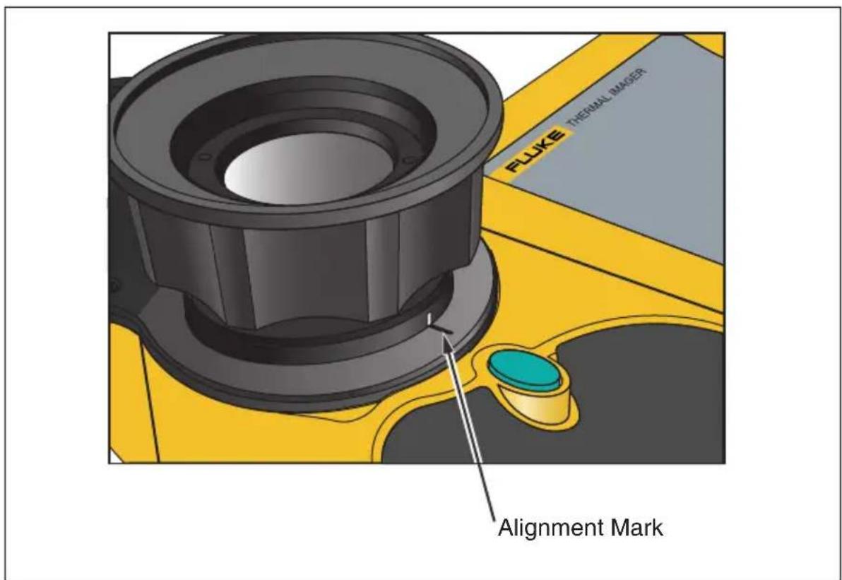
Image alignment is disabled when using the optional 10 and 54-mm lenses. To ensure proper image alignment with the standard 20-mm lens, the lens must be aligned correctly when you install it on the camera. Correct alignment is achieved by installing the lens such that the white alignment marking on the lens lines up with the corresponding mark on the camera housing as shown in Figure 5-1.
text_image
FLUKE THERMAL IMAGER Alignment Markeii021.eps
Figure 5-1. Aligning the 20-mm Lens
Focusing
Prior to capturing images using the visible light module and IR-Fusion®, it is important to make sure the target object is in focus. As you rotate the infrared (IR) lens to focus the camera, if the IR blend is less than 50%, the IR-Fusion® blend level changes to 50% infrared and 50% visible light (VL). Once you have the target object in focus and stop rotating the IR lens, the IR-Fusion® level returns to your setting. You can focus the infrared portion of the image only; the focus of the VL portion is set at the factory.
To focus the camera, remove the IR lens cap, point the lens at the target, and manually rotate the infrared lens with your finger. Focus by aligning the edges of the IR and VL images.
Adjusting IR-VL IR-Fusion® Blend Level
Note
This feature is disabled with optional 10 and 54-mm lenses.
You can change the IR-Fusion® blend level from full infrared (IR) to full visible light (VL) or some combination in between. When the IR-Fusion® blend level is set to full IR, 100% of the image is IR. When the IR-Fusion® blend level is set to full VL, 100% of the image is VL. When the IR-Fusion® blend level is set somewhere in the middle of full IR and full VL, an appropriate amount of the image is IR and an appropriate amount is VL, thus displaying a fused—or blended—image.
To adjust the IR-VL Fusion blend level using the level & span button and mouse controller:
- Press and hold Ⓤ until the IR-Fusion® level dialog box appears near the bottom of the screen.
-
While continuing to hold ⏰, move the mouse controller left or right to desired setting, or use SELECT to position the pointer over the Full IR or Full VL text to quickly move to 100% infrared or 100% visible light respectively.
-
Tap ☐ to accept setting change and return to scan target mode.
To adjust the IR-VL IR-Fusion® blend level from the popup menu:
-
Tap MENU.
-
Use the mouse controller to position the pointer over Camera Settings on the popup menu and tap SELECT.
-
Position the pointer over the VLCM tab and tap SELECT. You may need to position the pointer over the right or left arrow on the tab bar and tap SELECT to scroll to the VLCM tab.
-
Position the pointer over the Full IR/Full Visible bar; press and hold SELECT and then move the mouse controller left or right to desired setting.
-
Tap Ⓞ to accept setting change and return to scan target mode.
Using Full Screen or Picture-in-Picture View
In the full screen view, the infrared (IR) target object image takes up the entire display screen using the IR-Fusion ^® blend setting you have selected. For example, if the IR-Fusion ^® blend setting is Full IR, then the infrared image is displayed. If the IR-Fusion ^® blend setting is Full Visible, then the visible light (VL) image is displayed. If the IR-Fusion ^® blend setting is somewhere in between, this image blend is displayed. Temperature values are available on all areas of the display screen. The centerpoint, centerbox, and hot and cold points are available in full screen view, and user-defined point and box markers are fully editable in this view.
In the picture-in-picture view, the fused, or blended, infrared/visible light image appears in a rectangle in the center quarter of the display screen. The visible light image appears in the rest of the display screen. The centerpoint, centerbox, and hot and cold points are available in the picture-in-picture view. User-defined point and box markers are fully editable in this view.
Temperature readings are available only within the infrared image area. The visible light image field of view is larger than the infrared field of view, thus enabling the infrared picture to fit inside the visible light picture (picture-in-picture).
To choose full screen or picture-in-picture view:
- Tap MENU.
- Use the mouse controller to position the pointer over Camera Settings on the popup menu and tap SELECT.
- Position the pointer over either the Full Screen or Picture-in-Picture radio button as desired.
- Tap Ⓞ to accept setting change and return to scan target mode.
Or, assign the Picture-in-Picture function to a programmable button (see Chapter 2). Then, to cycle between full screen and picture-in-picture views, tap F1, F2, or F3 as needed.
Adjusting Brightness and Color Controls
Use the brightness and color controls to adjust the visible light image according to your personal preference.
To enable high brightness and/or vivid color:
- Tap MENU.
- Use the mouse controller to position the pointer over Camera Settings on the popup menu and tap SELECT.
- Position the pointer over the VLCM tab and tap SELECT.
You may need to position the pointer over the right or left arrow and tap SELECT to scroll to the VLCM tab. - Position the pointer over the High Brightness box; tap SELECT to add or remove a check mark. A check mark indicates the function is enabled.
- Position the pointer over the Vivid Color box; tap SELECT to add or remove a check mark. A check mark indicates the function is enabled.
- Tap to accept setting change and return to scan target mode.
Using Torch Control
When working in darker areas, you can enable the torch function to provide better lighting. If the flash is not enabled, but the torch function is, the torch remains on during image capture. The torch operates at approximately 50% power continuously; the flash operates at full power the instant the image is captured.
Note
The torch can be enabled at the same time the flash is enabled. If both functions are enabled, the torch operates continuously, while the flash comes on during the image capture. The torch enabled function times out after 60 seconds. Limit torch use to save battery power.
Assign the Torch function to a programmable button (see Chapter 2). Then, to cycle between torch on and torch off, tap F1, F2, or F3 as needed.
Using Visible Light Flash
When working in darker areas, you can enable the flash function to light the target object and capture better-quality visible light images. When the flash is enabled, it operates with one burst of light when an image is captured (the moment the image is paused).
Note
The flash can be enabled at the same time the torch is enabled. If both functions are enabled, the torch operates continuously, while the flash comes on during the image capture. The torch function times out after 60 seconds, and it can also be turned off by pressing the assigned function button again. The flash does not time out.
To enable the flash:
- Tap MENU.
- Use the mouse controller to position the pointer over Camera Settings on the popup menu and tap SELECT.
- Position the pointer over the VLCM tab and tap SELECT. You may need to position the pointer over the right or left arrow and tap SELECT to scroll to the VLCM tab.
- Position the pointer over the Flash Enabled box; tap SELECT to add or remove a check mark. A check mark indicates the function is enabled.
- Tap to accept setting change and return to scan target mode.
Recording Visible Light Images
With the visible light camera module, you can simultaneously save both an infrared image and the corresponding visible light control image. However, you may not want to save the visible light image along with every infrared image you capture; a visible light image captured with the infrared image takes up much more space on the CompactFlash memory card. You can enable or disable the record control image function as needed.
With this function enabled, both the visible light and the infrared images are captured. You can view the images using the Full IR or Full Visible settings or blended in between. With the record control image function disabled, only the infrared image is saved.
Note
The setting to either record or not record control images is governed by the setting to enable or disable the visible light camera module (VLCM). The VLCM must be enabled to capture a visible light control image; see Enabling/Disabling Visible Light Camera Module earlier in this Chapter).
To enable the record control image function:
- Tap MENU.
- Use the mouse controller to position the pointer over Camera Settings on the popup menu and tap SELECT.
- Position the pointer over the VLCM tab and tap SELECT.
You may need to position the pointer over the right or left arrow and tap SELECT to scroll to the VLCM tab. - Position the pointer over the Enable Visible Light Camera box; tap to add or remove a check mark. A check mark indicates the function is enabled.
- Tap to accept setting change and return to scan target mode.
Using Laser Pointer
W Warning
*To avoid injury, use your camera's Class 2 laser pointer only as instructed.
Use the laser function to help you point out the object you are aiming the camera towards. For example, use the laser to show a colleague where a problem is physically located. Using appropriate IR-Fusion® blend levels and color palette settings allows the red laser dot to be in the visible light image only.
Assign the Laser function to a programmable button (see Chapter 2). Then, press and hold F1, F2, or F3 to use the laser; release when finished. An icon appears on the display screen to indicate the laser is activated.
Using Thumbnail Browser
Assign the Thumbnail Browser function to a programmable button (see Chapter 2).
Use the radio buttons on the thumbnail browser window to switch between IR-only, fused, and VL-only image thumbnail displays. Selecting one of these views does not change the image file; fused images are rendered according to the blend level setting for each image file.
Using Color Alarms
Note
This feature is not available on the TiR3 or Ti50.
The color alarm function allows you to highlight target object areas of thermal interest by selectively fusing the visible light image with portions of the infrared image. For example, you can specify a temperature range. Then, any target object temperatures either inside or outside of the range, depending on what you set, are highlighted in the infrared color that corresponds to that temperature (based on the color palette settings).
You can choose to highlight temperatures either inside or outside of the range specified. You can also choose to highlight only temperatures above or below a threshold setting.
Color alarm thresholds and range limits can be adjusted using the display screen menu.
Note
Color alarms work in both full screen and picture-in-picture view. With the onscreen alarm disabled, the entire infrared image is blended with the visible light image according to the IR-Fusion ^® blend setting and palette selection. The IR-Fusion ^® blend setting should include some IR (i.e., not full VL) so that the color alarm is visible on the display screen, provided objects in the scene meet the color alarm criteria.
Using Menu to Adjust Color Alarm Ranges
To enable/disable onscreen alarm:
- Tap MENU.
- Use the mouse controller to position the pointer over Image Settings on the popup menu and tap SELECT.
-
Position the pointer over the Color Alarms tab and tap SELECT. You may need to position the pointer over the right or left arrow and tap SELECT to scroll to the Color Alarms tab.
-
Position the pointer over the Enable Onscreen Alarm box; tap SELECT to add or remove a check mark. A check mark indicates the function is enabled.
- Tap to accept setting change and return to scan target mode.
To set color alarms for temperatures either inside or outside of the specified temperature range:
- Follow steps 1-4.
- Position the pointer over the “Temperatures Are Inside Specified Range” checkbox; tap SELECT. A check mark indicates that temperatures within the range will be used.
- If you have selected "Alarm Outside Range," position the pointer over the Max or Min box as desired; tap SELECT to add or remove a check mark. A check mark indicates the function is enabled.
If you selected “Temperatures are Inside Specified Range,” you cannot change the Max or Min check boxes.
- Continue to Step 10 to set the alarm temperature range, or go to Step 12 if finished.
To set color alarm temperature range (maximum and minimum temperatures): - Follow steps 1-4.
-
You can increase or decrease values rapidly to get near the value you want:
-
Position the pointer over either the Max or Min temperature value; tap SELECT; the box becomes highlighted. Use the mouse controller up/down action to quickly adjust the value in large increments. Tap SELECT again to enter the selected value.
-
Increase or decrease values slowly one digit at a time to hit the exact value you want, position the mouse pointer over the value's corresponding right/left arrows, then tap SELECT as needed until you reach value you want.
-
Tap to accept setting change and return to scan target mode.
Using Palette Bar to Adjust Color Alarm Ranges
If you have enabled color alarms, the color alarm temperature limits are indicated next to the color palette on the display screen.
To adjust the color alarm temperature limits from the color palette:
- Position the pointer over the color alarm temperature limit you want to change, then tap SELECT to highlight the value.
- Use the mouse controller up/down action to change the value.
- When you reach the desired temperature, tap Ⓞ to accept setting change and return to scan target mode.
Adjusting Display Screen Brightness
You can adjust the display screen brightness for better viewing options in various lighting conditions.
Note
For maximum battery life, use the dimmest setting possible that still enables you to clearly see the display screen images.
To adjust the display screen brightness and high brightness timeout time:
- Tap MENU.
- Use the mouse controller to position the pointer over Camera Settings on the popup menu and tap SELECT.
- Position the pointer over the Power tab and tap SELECT.
- Position the pointer over the Display Brightness down arrow and select. Then position the pointer over the desired brightness level from the pull down menu and select.
- If you select “bright,” you can also select a “high brightness timeout” time: Position the pointer over the High Brightness Timeout down arrow and select the time you wish.
- Tap to accept setting change and return to scan target mode.
You can also assign the Brightness function to a programmable button (see Chapter 2). Then, tap the programmable button as needed to adjust the display screen brightness.
Hiding Display Screen Task Bar
For more image viewing area, you can hide the display screen task bar.
Specifically, you can set the task bar to automatically disappear within 3 seconds when the mouse pointer is moved off the bottom row of the camera display screen or if the pointer remains stationary on the task bar (above the bottom row) for 4 seconds.
To enable the Auto-Hide Task Bar function:
- Tap MENU.
- Use the mouse controller to position the pointer over Image Settings on the popup menu.
- Tap SELECT.
- Position the pointer over the Display tab and tap SELECT.
- Position the pointer over the Auto-Hide Task Bar box and tap SELECT. A check mark indicates function is enabled.
- Tap ☐ to accept setting change and return to scan target mode.
To make the task bar reappear while the Auto-Hide function is enabled, use the mouse controller to position the pointer on the bottom row of the display screen. As long as the pointer remains on the bottom row of the display screen, the task bar stays on, even if the Auto-Hide Task Bar function is enabled.
To hide the task bar while the Auto-Hide function is enabled, use the mouse controller to move the pointer off the bottom row of the camera display screen.
Hiding Display Screen Color Palette
For more image viewing area, you can hide the display screen color palette.
To hide the color palette:
- Tap MENU.
- Use the mouse controller to position the pointer over Image Settings on the popup menu.
- Tap SELECT.
-
Position the pointer over the Display tab and tap SELECT.
-
Position the pointer over the Temperature Scale box and tap SELECT. A check mark indicates function is enabled.
- Tap 0 to accept setting change and return to scan target mode.
Setting Temperature Units
To set or change temperature units to Celsius, Fahrenheit, or Kelvin:
- Use the mouse controller to position the pointer over the temperature unit mark (°F, °K, °C) on the task bar and tap SELECT.
- Repeat until the desired unit is selected.
Setting Temperature Calibration Range
You can change the temperature calibration range as needed: the narrower the range the better the image quality, which enables you to see smaller temperature variances. The wider the range the lower the image quality; however, you are able to see a greater range of temperature variances.
To set the temperature calibration range:
Note
Calibration range cannot be changed on a paused or saved image. Be sure to select the correct calibration range prior to pausing or saving an image. See Appendix D to determine the calibrated temperature ranges available for your camera model.
- Tap MENU.
- Use the mouse controller to position the pointer over Camera Settings on the popup menu and tap SELECT.
- Position the pointer over the Lens tab and tap SELECT.
- Position the pointer over the calibration range radio button you want and tap SELECT.
- Tap to accept setting change and return to scan target mode.
Changing Lens Selection
To change the lens selection to match the installed lens:
Note
Lens selection cannot be changed on a paused or saved image. Be sure to select the correct lens prior to pausing or saving an image.
- Tap MENU.
- Use the mouse controller to position the pointer over Camera Settings on the popup menu and tap SELECT.
- Position the pointer over the Lens tab and tap SELECT.
- Position the pointer over the Lens down arrow and select, then position the pointer over the appropriate lens from the pull down menu and select.
- Tap ☐ to accept setting change and return to scan target mode.
Setting Date and Time
Your Camera has an internal calendar and clock. The calendar is used in naming saved images. The date and time are recorded within an image when the image is saved (see Chapter 3).
To change the date:
- Use the mouse controller to position the pointer over the date field on the task bar.
- Tap SELECT.
- Position the pointer over the Date down arrow and select. A monthly calendar appears.
• To change the month and day:
- Position the pointer over the left/right arrows and tap SELECT as needed to scroll one month at time until you reach the month you want.
• Position pointer over the desired day and tap SELECT.
• To change the year:
• Position the pointer over the year and tap SELECT.
- Position the pointer over the up/down arrows and tap SELECT as needed to scroll one year at a time until you reach the year you want.
- Tap Ⓞ to accept setting change and return to scan target mode.
To change the time:
- Use the mouse controller to position the pointer over the time field on the task bar.
- Tap SELECT.
- Position pointer over the Time field you are changing (hour, minute, or second if available) and tap SELECT.
- Position the pointer over the up or down arrow next to the time field and tap SELECT repeatedly to scroll to the desired time.
- Repeat Steps 3-4 to change other fields.
- Tap ☐ to accept setting change and return to scan target mode.
To change the date format:
- Use the mouse controller to position the pointer over the date field on the task bar.
- Tap SELECT.
- Position the pointer over the Locale tab and tap SELECT.
- Position the pointer over the Date down arrow and select.
- Position pointer over either the up or down arrow and tap SELECT as needed to scroll to the desired date format.
- Position pointer over the desired format and tap SELECT.
- Tap to accept setting change and return to scan target mode.
To change the time format:
- Use the mouse controller to position the pointer over the time field on the task bar.
- Tap SELECT.
- Position the pointer over the Locale tab and tap SELECT.
- Position the pointer over the time down arrow and select.
- Position pointer over the desired format and tap SELECT.
- Tap Ⓞ to accept setting change and return to scan target mode.
Changing the Language
To change the language setting:
- Tap MENU.
- Use the mouse controller to position the pointer over Camera Settings on the popup menu.
- Tap SELECT to select.
- Position the pointer over the Locale tab and tap SELECT to select.
- Use the mouse controller and SELECT to choose the desired language setting from the Language pull down menu.
- Tap 0 to accept setting change and return to scan target mode.
Saving and Reloading Camera Settings
You can save your current camera settings to a Compact Flash card (recommended if using a shared camera to access your custom settings on multiple cameras) or to the camera's internal memory (recommended if there is only one user). When you power on your Camera, settings such as the color palette, temperature units, programmed function buttons, etc., that you previously saved are loaded from the memory card into the camera operating memory. If you are not using a memory card or if the memory card has no stored settings, camera factory settings are loaded first followed by any internal camera settings you previously saved. Internal camera settings override the factory settings. Visible light camera module (VLCM) settings are saved and loaded just as other settings are.
To save current camera settings to the camera's internal memory or to a Compact Flash card:
- Tap MENU.
- Use the mouse controller to position the pointer over Camera Settings on the popup menu.
- Tap SELECT.
- Position the pointer over the Save tab and tap SELECT.
-
Position the pointer over either Compact Flash or Internal in the Save Settings To row and tap SELECT.
-
Tap to accept setting change and return to scan target mode.
To reload camera settings from the memory card or to load camera settings from a different card without powering off the camera:
- Tap MENU.
- Use the mouse controller to position the pointer over Camera Settings on the popup menu.
- Tap SELECT.
- Position the pointer over the Save tab and tap SELECT.
- Position the pointer over Compact Flash in the Load Settings From row and tap SELECT.
- Tap ☐ to accept setting change and return to scan target mode.
To restore factory settings:
- Tap MENU.
- Use the mouse controller to position the pointer over Camera Settings on the popup menu.
- Tap SELECT.
- Position the pointer over the Save tab and tap SELECT.
- Position the pointer over Restore Factory Settings and tap SELECT.
- Tap ☐ to accept setting change and return to scan target mode.
Naming Image Files
When you save an image, its name is added to the upper left corner of the image display.
An image name looks like this: IR00020060515_0001
- IR is prefix (The prefix assigned to the image is based on the prefix last assigned and stored in the camera settings.)
• 20060515 is the eight-digit date
• 0001 is the four-digit sequencing number
Changing Image File Name Prefix
To change the prefix used in the saved image name:
Note
This change affects only new images saved to the memory card and does change the prefix of previously saved images.
- Tap MENU.
- Use the mouse controller to position the pointer over Camera Settings on the popup menu.
- Tap SELECT.
- Position the pointer over the Files tab and tap SELECT.
- Position the pointer over Edit and tap SELECT to open the Prefix Editor.
- Select and click on up to five alphanumeric characters one at a time. Tap to accept setting change and return to Camera Settings window.
- Tap ○ again to return to scan target mode.
Resetting Image File Name Sequence Number
To change the file sequence number used in the saved image name:
Note
If a file sequence number you want to use for image B is already used for image A, the camera automatically selects the lowest possible sequence number for image B and does not override, or delete, image A.
- Tap MENU.
- Use the mouse controller to position the pointer over Camera Settings on the popup menu.
- Tap SELECT.
- Position the pointer over the Files tab and tap SELECT.
- Position the pointer over Reset and tap SELECT to reset the sequence numbers back to 0000.
- Tap Ⓞ to accept setting change and return to scan target mode.
Selecting Video Output Options
Using the video port and video cable, you can display the live, paused, or saved images on a TV, video projector, or video monitor. You can also record images on a video recorder.
Video output can be set to NTSC, PAL, or disabled.
Note
Disable the video output function when not in use to save battery power.
To select NTSC or PAL signal and enable/disable video output:
- Plug the video cable (the end with the cylindrical noise suppressor) into the camera video port; plug the other end of the cable into the TV, projector, monitor, or video recorder.
-
Tap MENU on the camera.
-
Use the mouse controller to position the pointer over Camera Settings on the popup menu.
- Tap SELECT.
- Position the pointer over the Locale tab and tap SELECT.
- Position the pointer over either the PAL or NTSC video signal radio button and select. The black circle indicates setting is enabled.
- Position the pointer over the Power tab and select.
- Position the pointer over the Video Output Enabled button and select. A check mark indicates function is enabled. When not in use, disable this function to conserve battery power.
- Tap ☐ to accept setting change and return to scan target mode.
Chapter 7
Advanced Operation
Enhancing the Image
You can use the image enhancement function to improve image clarity in live scan targets and images saved while this function is enabled. Image quality improves with each increase in image enhancement; however, response times are increased accordingly, for example, images set to “Normal” image enhancement refresh a screen at a faster update rate than images set to “High.”
Note
Higher settings are more likely to show blurring on moving targets. Image enhancement cannot be applied to images after they are paused or saved. To use image enhancement, be sure to enable the function prior to scanning target areas and saving images.
To adjust the image enhancement level:
- Tap MENU.
- Use the mouse controller to position the pointer over Image Settings on the popup menu and tap SELECT.
- Position the pointer over “None,” “Normal,” “Medium,” or “High” and tap SELECT.
- Tap Ⓞ to accept setting change and return to scan target mode.
Using Auto Capture
Note
This feature is available on TiR2, TiR4, Ti45 and Ti55 models only.
With the Auto Capture function, you can record a sequence of one or more images by specifying the number of images to be captured and the time
interval between images. Use the Auto Capture function to scan multiple target areas and quickly save the images.
Note
Actual number of saved images depends on the capacity of your memory card.
You can set the Auto Capture sequence to be either manually or temperature triggered. When manually triggered, the camera begins capturing images immediately after you activate the function. Or, you can choose a single camera temperature measurement point (such as the hot and cold cursors, center point, mouse point, and up to three user-defined points) or the minimum, maximum, or average temperatures of any of the area markers (center box plus up to three user-defined areas) to trigger the image capturing sequence.
Note
When using the Auto Capture function with the visible light camera module (VLCM), the rate at which images are captured is slowed considerably if you include visible light images. Turning off the VLCM will keep the rate of images captured at approximately one image per 1 to 2 seconds for 160 x 120 cameras and one image per 2 to 3 seconds for 320 x 240 cameras. When the VLCM is enabled, the rate of images captured is approximately seven seconds.
To manually trigger the Auto Capture function:
- Tap MENU.
- Use the mouse controller to position the pointer over Image Settings on the popup menu and tap SELECT.
- Position the pointer over the PIC tab and tap SELECT.
- Position the pointer over the right or left arrows next to Max Images to set the number of images you want to capture in the sequence.
- Position the pointer over the right or left arrows next to Interval (sec) to set the number of seconds between images.
- Position pointer over the Manual radio button and select.
- Tap Ⓞ to accept setting change and return to scan target mode.
To trigger the Auto Capture function using a temperature setting:
- Tap Ⓜ, then use the mouse controller to position the pointer over Image Settings on the popup menu.
- Tap SELECT.
- Position the pointer over the Auto Capture PIC tab and tap SELECT.
- Position the pointer over the right or left arrows next to Max Images and tap and hold SELECT as needed to set the number of images you want to capture in the sequence.
Click Check Space to see how many more images you can fit on the memory card.
- Position the pointer over the right or left arrows next to Interval (sec) and press and hold SELECT as needed to set the number of seconds between images.
- Position the pointer over the Temperature radio button and select.
- Select the measurement point from the pull-down menu (Mouse, CenterPoint, CenterBox, Hot cursor, Cold cursor, and user-defined points and areas from pull-down list; for areas, select from Min. Avg., Max.).
- Select the Over or Under radio button.
- Use the right/left arrows to set the temperature trigger point.
- Select the “Save all images after trigger” box if you want to save all images after the initial trigger, or, leave the box unchecked to save only images that meet the trigger criteria. (When the “Save all images after trigger” box is checked, an image is captured after each time interval following the initial trigger, even if the temperature condition changes. If the box is unchecked, images are captured after each time interval only when the specified temperature condition is true.)
- Tap to accept setting change and return to scan target mode.
Using User-Defined Display Screen Temperature Markers
Note
This feature is available on TiR2, TiR4, Ti45 and Ti55 models only.
In addition to basic display screen temperature markers (see Chapter 4), the IR-FlexCam offers the following advanced marker options available in scan target mode and/or on a saved image you open:
- Up to three user-defined spot temperatures each marked with a crosshair.
- Up to three user-defined area markers each indicated by a custom-sized box.
To enable the user-defined spot temperature and area markers:
- Assign the Marker toolbar visible function to a programmable button (see Chapter 2).
- From scan target mode or from an open image, tap the programmable button; the Marker toolbar appears in the upper left corner of the display screen.
To add spot temperature markers to the display screen from either scan target mode or from an open image:
- Use the mouse controller to position the pointer over the crosshair icon in the Marker toolbar.
- Tap SELECT.
- Use the mouse controller to position the mouse crosshair over the image spot desired.
- Tap SELECT to place a spot temperature marker. The marker name, followed by the temperature of that spot appears on the display screen.
- Repeat Steps 3-4 to add up to two additional spot temperature markers.
- Select the rectangle icon from the Marker toolbar to add area markers (see the next set of procedures), or tap the programmable button to close the Marker toolbar and return either to scan target mode or to the open image. From an open image, tap 📋 again to return to scan target mode.
To add area markers to the display screen from either scan target mode or from an open image:
- Use the mouse controller to position the pointer over the rectangle icon in the Marker toolbar.
- Tap SELECT.
- Use the mouse controller to move the pointer to the image area desired.
- Tap Ⓗ to place the starting point, then use the mouse controller up/down/left/right action to drag the rectangle marker over the desired area. Continue moving the mouse controller as needed to create the desired rectangle size and shape.
- Tap SELECT to complete the area marker; the marker name, followed by the minimum, average, and maximum temperatures of that area, appear on the display screen.
- Repeat Steps 3-5 to add up to two additional area markers.
- Select the crosshair icon from the Marker toolbar to add spot temperature markers (see the procedures earlier in this Chapter), or tap the programmable button to close the Marker toolbar and return either to scan target mode or to the open image. From an open image, tap 📋 again to return to scan target mode.
To change the emissivity or background temperature value of spot temperature and/or area markers from either scan target mode or from an open image:
- Use the mouse controller to position the pointer over either the crosshair or rectangle icon in the Marker toolbar; tap SELECT.
- Use the mouse controller to position the pointer over the up/down arrows in the Marker toolbar; tap SELECT as necessary to scroll to the desired spot temperature or area marker name.
- Use the mouse controller to position the pointer over the emissivity value (left box next to the up/down arrows) or the background temperature value (right box next to the X close window button); tap SELECT.
- Use the mouse controller to adjust the value up or down as desired; tap SELECT.
-
Repeat Steps 1-4 as needed.
-
Tap the programmable button to close the Marker toolbar and return either to scan target mode or to the open image. From an open image, tap again to return to scan target mode.
To remove, rename, or annotate spot temperature and/or area markers from either scan target mode or from a open image:
- Use the mouse controller to position the mouse crosshair/pointer over either the crosshair or the rectangle icon; tap SELECT.
- Use the mouse controller to position the pointer over either the spot marker point or area marker point you want to remove. The mouse crosshair can be positioned anywhere on or near the spot marker; for area markers, the mouse pointer tip must be touching the area marker.
-
Tap Ⓜ; a pop up menu appears. Use the mouse controller to position the pointer over the desired option: Remove, Rename, or Annotate.
-
If you select remove, the marker is removed from the display screen.
- If you select rename, the Edit Marker Name keyboard appears.
- Enter a new marker name using the mouse controller to position the pointer over the appropriate letter and/or function, then press SELECT. Repeat as needed.
- If you select Annotate, the Annotations editor appears.
-
Use the mouse controller to position the pointer over the desired annotations (see Chapter 4) and press SELECT.
-
Tap ☐ to accept the setting change and return to scan image mode or to the open image. From an open image, tap ☐ again to return to scan target mode.
To move point and area markers:
- Use the mouse controller to position the mouse pointer over the label text for a marker. The pointer arrow changes to a “pointing hand.”
- Press and hold SELECT while using the mouse controller to "drag" the marker to a new location.
To resize area markers:
- Use the mouse controller to position the mouse pointer over an area edge or corner. The pointer arrow changes to a "pointing hand."
- Press SELECT while using the mouse controller to adjust the size of the area marker as desired.
Using Internal Recalibration
Your Camera has an internal calibration feature that automatically adjusts the camera electronics as needed to maintain a high quality image even when the camera senses a significant change in either internal temperature or temperature at the target object. During an internal calibration, you may hear a faint “double click” sound from the camera and see the word “Calibrating” appear on the display screen. The image is frozen for approximately 1-2 seconds during the calibration process.
You may also want to manually trigger an internal calibration to adjust for changing environmental conditions, for example, you move from an extremely cold environment to a hot environment (see Programming Function Buttons in Chapter 2).
Cleaning the IR Lens, VLCM, Display Screen, and Body
For optimal performance, your Camera should be treated with care and gently cleaned as needed. You should always take great care whenever you touch the lens or display screen. The lens elements are made from Germanium crystal and easily can shatter or be scratched and chipped, and the liquid crystal display (LCD) screen is sensitive to excess pressure. To protect your Camera, replace the lens cap and store the camera in the case when you are not using the camera.
Caution
To avoid damaging your camera, use compressed air to remove large particles and dust prior to using a cloth.
To clean the IR lens and the VLCM lenses and windows:
- Lightly rub the lens with a soft cotton cloth slightly moistened (not dripping) with a non-abrasive solution marked for lens cleaning or a mild, diluted dish soap solution (never use solvents).
To clean the display screen:
- Lightly rub the display screen with a clean computer monitor cleaning cloth.
To clean the camera body:
- Lightly rub the camera body with a clean, slightly damp cloth. Dampen the cloth in a solution of water and a small amount of mild soap if needed.
Using Other Lenses
Your Camera comes standard with an f 0.8 20-mm focal length lens, which is appropriate for most applications. The lens is made of Germanium crystal and is antireflection coated for high transmission in the 8 to 14 micron wavelength band. Two additional lenses are available: a wide angle f 0.8 10.5-mm focal length lens to capture larger targets at short distances and a narrow angle f 1.0 54-mm focal length lens to capture small targets at long distances.
When you change lenses, you must change the lens selection setting accordingly as described in Chapter 6. Ensure proper alignment when connecting the standard 20-mm lens. See Chapter 5, Using Image Alignment for more information.
For more information on ordering additional lenses or other accessories, visit www.fluke.com.
Viewing Camera and Battery Information
The Info tab within the Camera Info window contains a list of key features such as IR refresh rate, IR image size (in pixels), zoom capabilities, IR-Fusion® capabilities, camera serial number, software versions, lens descriptions of each lens used (if more than one), calibration range, number of image files on the memory card, and the used and free space on the memory card.
To view the Info tab information:
- Tap MENU.
- Use the mouse controller to position the pointer over Camera Info on the popup menu and tap SELECT.
- Position the pointer over the Info tab and tap SELECT.
- Position the pointer over the up/down arrows to scroll and see additional details.
- Tap 0 to return to scan target mode.
The Battery tab within the Camera Info window shows the power source, remaining battery charge level, and battery manufacturer, serial number, and number of discharge cycles.
To view the Battery tab information:
- Tap MENU.
- Use the mouse controller to position the pointer over Camera Info on the popup menu and tap SELECT.
- Position the pointer over the Battery tab and tap SELECT.
- Tap to return to scan target mode.
Charging the Batteries
Your Camera comes with a battery charger that works with 100 to 240 V AC input voltage and 50 or 60 Hz input frequency. The charger has a recalibration feature to maintain correct capacity monitoring. When using battery power, a battery symbol appears in the far right side of the camera display screen task bar. The remaining charge capacity is indicated as shown in Table 8-1.
Table 8-1. Remaining Battery Charge Indicators
| Indicator | Battery | Power Rema |
| Green 25% to 100% | ||
| Yellow Less than 25% | ||
| Flashing/Solid Red Approximately 5 m | nutes until camera powers off. |
Use the mouse controller to position the pointer over the battery icon. Press SELECT to obtain an estimate of the remaining battery charge and camera runtime.
To charge camera batteries:
Note
Charge at least one battery for 3 hours before use. Two batteries charge sequentially. The second battery remains in standby mode until the first battery is charged.
- Connect battery charger AC power supply to a power outlet. An outlet adapter may be necessary outside of the United States.
- Connect the power supply to the dual-bay battery charger.
- Insert one battery into one of the battery charger bays; insert the second battery—if available—into the second charger bay.
The LED indicator in front of each bay indicates the charging status as shown in Table 8-2.
Table 8-2. Battery Charging Status
| LED Indicator Charging Status | |
| Off No battery detected | |
| Green Flashing Fast charging | |
| Green Solid Fully charged | |
| Yellow Flashing Recalibrating | |
| Yellow/Green Recalibrated | |
| Yellow Solid Standby | |
| Red Flashing Error | |
Recalibrating the Batteries
You should recalibrate your camera batteries periodically to maintain the accuracy of the battery gauge. If a battery requires recalibration, a warning popup window appears on the camera display screen when you power on your camera.
Note
Recalibration may take up to 16 hours. You can charge a battery in the right charging bay while recalibrating a battery in the left bay.
To recalibrate a battery:
-
Insert the battery into the left bay of the battery charger.
-
Press the recalibrate button on the front of the charger.
Conserving Battery Power
To conserve battery power (when the camera is running on battery power, not AC power), the display screen automatically powers off and the system goes into standby mode when the system has been idle for 5 minutes (you can change this time). The camera automatically powers off when the system has been in standby for 10 minutes (you can change this time). You can manually switch to standby mode as well.
To manually switch from full power to standby mode, tap ⏻ once. ⏻ flashes green.
To switch from standby mode to full power, tap ⏻ once again. ⏻ remains solid green.
To power on or off, press and hold ⏻ for 4 seconds. ⏻ remains solid green when power on; no light when power off.
To change the standby timeout time:
-
Tap MENU.
-
Use the mouse controller to position the pointer over Camera Settings on the popup menu.
-
Tap SELECT.
-
Position the pointer over the Power tab and tap SELECT.
-
Position the pointer over the Standby Timeout down arrow and press SELECT.
-
Position the pointer over the time you want and press SELECT.
-
Tap ☐ to accept setting change and return to scan target mode.
To change the standby to off timeout time:
- Tap MENU.
- Use the mouse controller to position the pointer over Camera Settings on the popup menu.
- Tap SELECT.
- Position the pointer over the Power tab and tap SELECT.
- Position the pointer over the Standby To Off Timeout down arrow and press SELECT.
- Position the pointer over the time you want and press SELECT.
- Tap ☐ to accept setting change and return to scan target mode.
Appendices
Appendix
Title
Page
A Glossary.... A-1
B Troubleshooting...... B-1
C Emissivity Values C-1
D Camera Specifications and Dimensions...... D-1
E Resources and References ...... E-1
F Camera Default Settings F-1
Appendix A Glossary
Background Temperature
The temperature of the surroundings, as seen by the target object. In practical terms, this is often considered to be the ambient or room temperature. When outdoors, this can be a very difficult value to estimate, due to the effects of very hot (the sun) and cold (clear sky) objects. By paying careful attention to the location of and direction from which an object is photographed, the effects of very hot and cold objects in the background can often be minimized.
Blackbody
A blackbody is a theoretically ideal radiator and absorber of energy at all electromagnetic wavelengths, i.e., a completely non-reflective object. The term comes from the fact that a cold blackbody appears visually black.
Color Palette
Color representation of the temperatures (temperature scale) in a displayed image.
Electro Static Discharge (ESD) event
A single-event, rapid transfer of electrostatic charge between two objects, usually resulting when two objects at different potentials come into direct contact with each other. ESD can also occur when a high electrostatic field develops between two objects in close proximity.
Emissivity
The ratio of the actual emitted radiance to that of an ideal blackbody at the same temperature. In practical terms, this means that objects with lower emissivity will be more affected by background radiation.
FAT or FAT16 file format
Stands for File Allocation Tables. Most computer operating systems store computer files by dividing the file into smaller pieces and storing those pieces in separate clusters of a hard disk, floppy disk, or Compact Flash memory card. The FAT file system allows an operating system to keep track of the location and sequence of each piece of a file, and also allows the operating system to identify which clusters are unassigned and available for new files. When a computer user wants to read a file, the FAT file system also reassembles each piece of the file into one unit for viewing.
Infrared Spectrum
The portion of the electromagnetic spectrum immediately adjacent to visible light; approximately from 0.7 m to microwave.
Infrared Camera
Electronics, lens, and detector combinations that give the user an image, that can be viewed or recorded, of energy in the infrared spectrum.
Infrared, Thermal
The portion of the infrared spectrum from which the majority of heat energy is recorded. This portion of the electromagnetic spectrum is defined as 3 m to microwave. However, the majority of infrared imaging occurs between 3 m and 14 m .
Isotherm
In general scientific terminology, an isotherm is set of lines on a thermogram that marks points that are of the same temperature.
Level
The center value of the color palette (temperature scale).
NTSC
The National Television Standards Committee (NTSC) sets the analog television standard for the United States; this format itself is also informally called “NTSC.” While a standard for the United States, NTSC format has been adopted in other countries as well, including Korea and Japan.
PAL
Phase Alternating Line is the analogue video format used in television transmission in most of Europe—except France, Bulgaria, Russia, Yugoslavia, and some other countries in Eastern Europe, where SECAM is used—Australia and some Asian, African, and South American countries.
Palette Temperatures
Maximum, center, and minimum temperatures (temperature scale) of the color palette.
Radiometric
The ability to measure thermal energy—or temperature—and display it back to the camera user.
Reflected energy
Any energy that does not radiate directly from the target object.
Saturation Colors
The ends of the color palette used to display temperature extremes, for example, a temperature greater than the palette maximum temperature and/or a temperature lower than the palette minimum temperature.
Span
The temperature range across which the color palette (temperature scale) is mapped.
Target
An object being thermally photographed.
Temperature Scale - The temperatures represented by the color palette (palette temperatures).
Thermography – The use of infrared thermography whereby temperatures of a wide variety of targets can be measured remotely and without contact. This is accomplished by measuring the infrared energy radiating from the surface of the target and converting this measurement to an equivalent surface temperature.
Thermogram - An infrared image.
Appendix B
Troubleshooting
For troubleshooting help, see the tips in Table B-1.
Table B-1. Troubleshooting Tips
| Symptom | Possible Reason Possible Solution |
| Camera will not power on. | The battery is not inserted. Insert a charged battery. |
| The battery is not charged. Charge the battery. See Chapter 8. | |
| An improper Compact Flash memory card is inserted. Use SanDisk-brand Compact Flash memory card with a 2003 or newer copyright date.⚠ CautionTo avoid problems saving images, do not use other memory card brands. |
Table B-1. Troubleshooting Tips (cont.)
| Symptom | Possible Reason Possible Solution | |
| Camera will not power on. | The Compact Flash memory card is corrupt. | Reformat* the memory card: Insert the Compact Flash card into a memory card reader installed on your computer. Use “Windows Explorer” or “My Computer” to view the memory card drive location. Right click on the drive and select the FAT or FAT16 file format.⚠ CautionTo prevent image data loss, do not use FAT32 format. Do not change any other settings.⚠ CautionTo prevent image data loss, be sure to transfer the images saved on the Compact Flash card to a computer hard drive and/or other back up storage device (e.g., CD-R disc) before reformatting the memory card. Reformatting the memory card will erase all images stored on the card. |
| An electrostatic discharge (ESD) event has taken place. | Use a paperclip to press reset. See Chapter 2. | |
| Camera will not save an image. | A Compact Flash memory card is not inserted or an unauthorized card is inserted. | Insert only a SanDisk-brand Compact Flash memory card with a 2003 or newer copyright date.⚠ CautionTo prevent image saving errors, do not use other memory card brands. |
| Camera will not save an image. | The Compact Flash memory card is full. | Insert new SanDisk-brand Compact Flash memory card, delete unnecessary images from the card (see Chapter 3), or transfer the images saved on the card to a computer hard drive and/or other back up storage device (e.g., CD-R disc). |
| The approximate sign (~) appears in front of a temperature reading. | The temperature reading is outside the selected calibration range and the accuracy may not be within the specified accuracy of the camera. | Change the temperature calibration range; See Setting Temperature Calibration Range, in Chapter 6. |
| Visible light and IR images are not properly aligned. | Incorrect focus, optional lenses, or 20-mm lens not properly aligned. | Image alignment is disabled with 10 and 54-mm lenses. Adjust the alignment after the images are downloaded to the SmartView software.Align the 20-mm lens such that the white alignment marking on the lens lines up with the corresponding mark on the camera housing as shown in Figure 5-1. |
If you are unable to solve the problem using the possible solutions in the Troubleshooting table:
Reboot the camera by pressing ⏻ to power off the camera, then pressing ⏻ again to power on the camera.
If this still does not correct the issue:
Contact Fluke as described in Chapter 1.
Before You Contact Us
To better assist you and to minimize your call time, please have the following information ready to share with a customer service representative before contacting Fluke Corporation:
- OCA Version, DSP Version, and MSP Version You will find this information in the Camera Info menu, Info tab (see Chapter 8).
- Serial Number and Part Number (twist lens module, then see label on the side of the camera body as shown in Figure B-1).

natural_image
Illustration of a yellow and gray handheld device with visible lens and control buttons (no text or symbols)eii015.eps
Figure B-1. Serial/Part Number and Laser Certification Location
Appendix C
Emissivity Values
Use the emissivity values shown in Table C-1 as a guide to properly setting the emissivity value on your Camera.
Table C-1. Emmisivity Values of Common Materials
| Material | Temperature (°C) Emissivity |
| Aluminum, polished 0 0.05 | |
| Aluminum, rough surface | 0 0.07 |
| Aluminum, strongly oxidized | 0 0.25 |
| Asbestos board 0 0.96 | |
| Asbestos fabric 0 0.78 | |
| Asbestos paper 0 0.94 | |
| Asbestos slate 0 0.96 | |
| Brass, dull, tarnished 0 0.22 | |
| Brass, polished 0 0.03 | |
| Brick, common 0 0.85 | |
| Brick, glazed, rough 0 0.85 | |
| Brick, refractory, rough 0 0.94 | |
| Bronze, porous, rough 0 0.55 | |
| Bronze, polished 0 0.10 |
Table C-1. Emissivity Values of Common Materials (cont.)
| Material | Temperature (°C) | Emissivity |
| Carbon, purified 0 0.80 | ||
| Cast iron, rough casting | 0 0.81 | |
| Cast iron, polished 0 0.21 | ||
| Charcoal, powdered 0 0.96 | ||
| Chromium, polished 0 0.10 | ||
| Clay, fired 0 0.91 | ||
| Concrete | 0 | 0.54 |
| Copper, polished, annealed | 0-17 | 0.01-0.02 |
| Copper, commercial burnished | 0 | 0.07 |
| Copper, oxidized 0 0.65 | ||
| Copper, oxidized to black | 0 | 0.88 |
| Electrical tape, black plastic | 0 | 0.95 |
| Enamel | 27 | 0.90 |
| Formica | 0 | 0.93 |
| Frozen soil 0 0.93 | ||
| Glass | 0 | 0.92 |
| Glass, frosted 0 0.96 | ||
| Gold, polished 0 0.02 | ||
| Ice | 0 | 0.97 |
| Iron, hot rolled 0 0.77 | ||
| Iron, oxidized | 0 0.74 | |
| Iron, sheet galvanized, burnished | 0 | 0.23 |
| Iron, sheet, galvanized, oxidized | 0 | 0.28 |
| Iron, shiny, etched 0 0.16 | ||
| Iron, wrought, polished 0 | 0.28 | |
| Lacquer, Bakelite 0 0.93 | ||
| Lacquer, black, dull 0 0.97 | ||
| Lacquer, black, shiny 0 | 0.87 | |
| Lacquer, white 0 0.87 | ||
| Lampblack | 0 | 0.96 |
| Lead, gray 0 0.28 | ||
| Lead, oxidized 0 0.63 | ||
| Lead, red, powdered 0 | 0.93 | |
| Lead, shiny 0 0.08 | ||
| Mercury, pure 0 0.10 | ||
| Nickel, on cast iron | 0 0.05 | |
| Nickel, pure polished | 0 0.05 | |
| Paint, silver finish | 25 | 0.31 |
| Paint, oil, average | 0 0.94 | |
| Paper, black, shiny | 0 0.90 | |
| Paper, black, dull | 0 0.94 | |
| Paper, white | 0 0.90 | |
| Platinum, pure, polished | 0 0.08 | |
| Porcelain, glazed | 0 0.92 | |
| Material | Temperature (°C) Emissivity | |
| Quartz | 0 | 0.93 |
| Rubber | 0 | 0.93 |
| Shellac, black, dull 0 0.91 | ||
| Shellac, black, shiny 0 0.82 | ||
| Snow | 0 | 0.80 |
| Steel, galvanized 0 0.28 | ||
| Steel, oxidized strongly 0 0.88 | ||
| Steel, rolled freshly 0 0.24 | ||
| Steel, rough surface 0 0.96 | ||
| Steel, rusty red 0 0.69 | ||
| Steel, sheet, nickel-plated | 0 | 0.11 |
| Steel, sheet, rolled 0 0.56 | ||
| Tar paper 0 0.92 | ||
| Tin, burnished 0 0.05 | ||
| Tungsten | 0 | 0.05 |
| Water | 0 | 0.98 |
| Zinc, sheet 0 0.20 | ||
Appendix D
Camera Specifications and Dimensions
Table D-1 lists the technical specifications for the TiR2, Ti45 and Ti40 models.
Table D-1. TiR2, Ti45 and Ti40 Specifications
| Model Name | Ti45 and TiR2 Ti40 | |
| Imaging Performance | ||
| Detector 160 | x 120 Focal Plane Array (FPA), vanadium oxide (VOX) uncooled microbolometer. | |
| Refresh Rate | Cameras have either 7.5 Hz or 30 Hz refresh rate. Use the Camera Info screen to determine the refresh rate for your specific camera. | |
| Spectral Band | 8 μm to 14 μm | |
| Thermal Sensitivity | ≤0.080 °C at 30 °C (80 mK) | ≤0.090 °C at 30 °C (90 mK) |
| Focusing Single Finger Manual Focus | ||
| Electronic 2x | None | |
| Model Name Ti45 and TiR2 Ti40 | ||
| Zoom | ||
| Digital Image Enhancement | Automatic Full-time Enhanced | |
| Display and Image Storage | ||
| Digital Display 5 in. | high-res, 320 x 240, sunlight readable color LCD | |
| On-screen Indicators | Indicate status of battery, target emissivity, background temp., temp. unit (C/F/K), date, and time | |
| Palettes 8 unique color palettes available | ||
| Storage Medium Compact Flash Card (stores hundreds of images) | ||
| File Formats Supported | 14 bit measurement data included. Exportable JPEG, BMP, TIF, PNG using SmartView desktop software | |
| Image Controls Level, Span, Auto Adjust (continuous/manual) | ||
| Image Browsing Full-screen and thumbnail | ||
| Enhanced Text Annotation | User definable, automatically included in reports | n/a |
| Programmable Image Capture | Automatically capture thermal images (program) | n/a |
| Standard Optics | ||
| 20mm f/0.8 Germanium | Field of View 23° Horizontal x 17° Vertical (optional lenses available) | |
| Spatial Resolution (IFOV) | 2.6 mrad IFOV, 0.15 m minimum focus | |
| Model Name | Ti45 and TiR2 Ti40 | |
| Temperature Measurement | ||
| Calibrated Temp. Ranges | Range 1 = -20 °C to 100 °C (-4°F to 212°F)Range 2, 3, and 4 are not available on the TiR2Range 2 = -20 °C to 350 °C (-4°F to 662°F)Range 3 = 250 °C to 600 °C (482°F to 1112°F)Range 4 = 500 °C to 1200 °C (932°F to 2192°F) (option) | Range 1 = -20 °C to 100 °C (-4°F to 212°F)Range 2 = -20 °C to 350 °C (-4°F to 662°F) |
| Accuracy | ±2 °C or ±2 %, whichever is greater | |
| Measurement Modes | Movable points & boxesCenterpointCursor temp.Center box (area min/max, average)Automatic hot and cold point detectionColor alarm | CenterpointCursor temp.Center box (area min/max, average) |
| Emissivity Correction | Based on user input. Variable from 0.01 to 1.0 (0.01 increments) | |
| Power | ||
| Battery Type | Li-Ion Smart Battery, rechargeable, field-replaceable | |
| Model Name Ti45 and TiR2 Ti40 | ||
| Battery Operating Time | 2-3 hours continuous operation for each battery, typical | |
| Battery Charging | 2-bay intelligent charger powered via AC outlet or optional 12 V from car | |
| AC Operation AC adapter 110/220 V ac, 50/60 Hz | Option | |
| Power Saving Automatic shutdown and standby modes (user specified) | ||
| Interfaces | ||
| Video Output RS170 EIA/NTSC or CCIR/PAL composite video | ||
| Physical Characteristics | ||
| Weight 4.4 lbs including battery | ||
| Size 71 mm x 262 mm x 196 mm (2.8 in x 10.5 in x 7.7 in) | ||
| Tripod Mounting 1⁄4 in – 20 UNC | ||
| Environmental | ||
| Operating Temp. | -10 °C to +50 °C (14 °F to 122 °F) | |
| Storage Temp. | -40 °C to +70 °C (-40 °F to 158 °F) | |
| Humidity Operating and storage 10 % to 95 %, non-condensing | ||
| Shock/Vibration | 25G, IEC 68-2-29 / 3G, IEC 68-2-6 | |
| Encapsulation IP54, IEC 60529 | ||
| Transit Drop MIL-STD-810F, Method 516.5, Procedure IV | ||
| Agency Approvals | CE Approved (EN61326 Standard) | |
| Model Name | Ti45 and TiR2 Ti40 | |
| Warranty | ||
| Two years and begins on date of shipment. | ||
| Standard Equipment | ||
| IR Camera with 20-mm f/0.8 lens | ||
| Compact Flash Card | ||
| USB Card Reader | ||
| SmartViewTM Software | ||
| Shoulder Strap | ||
| 2 Rechargeable Batteries | ||
| Premium Carrying Case | ||
| Battery Charger | ||
| User Manual | ||
| Video Cable | ||
| AC Adapter | ||
| Optional Equipment | ||
| Power Cable for 12 V from car to charger | ||
| Extra Batteries | ||
| Sun Shield | ||
| 54-mm Tele-photo Lens (9 °H x 6 °V) | ||
| 10.5-mm Lens (42 °H x 32 °V) | ||
| Extended temperature range 500 °C to 1200 °C (932 °F to 2192 °F) with 20mm lens | AC Adapter | |
| Visible Light Camera | ||
| Pixels | 1.3 M | |
| Active Pixels | 1280 H x 1024 V | |
| Field of View | 56° H x 46° V | |
| Sensitivity | 1 lux | |
| Focus Distance | 50 cm to infinity | |
| Exposure | Auto | |
| Integrated Flash | Manual or default for high quality visible light images | |
| Torch Light Mode | For enhanced video imaging in dark areas | |
| IR-Fusion® Modes | Full screen IR image blended with visible imagePicture-in-picture blended with visible imageAlarm mode | |
Table D-2 lists the technical specifications for the TiR3, TiR4, Ti55 and Ti50 models.
Table D-2. TiR3, TiR4, Ti55 and Ti50 Specifications
| Model Name Ti55 and TiR4 Ti50 and TiR3 | ||
| Imaging Performance | ||
| Detector 320 x 240 Focal Plane Array (FPA), vanadium oxide (VOX) uncooled microbolometer. | ||
| Refresh Rate C | cameras have either 7.5 Hz or 60 Hz refresh rate. Use the Camera Info screen to determine the refresh rate for your specific camera. | |
| Spectral Band 8 | μm to 14 μm | |
| Thermal Sensitivity | ≤ 0.050 °C at 30 °C (50 mK) | ≤ 0.070 °C at 30 °C (70 mK) |
| Focusing Single | Finger Manual Focus | |
| Electronic Zoom | 2x, 4x, 8x(2x, 4x when IR-Fusion® enabled) | 2x |
| Digital Image Enhancement | Automatic Full-time Enhanced | |
| Display and Image Storage | ||
| Digital Display 5 | in high-resolution, 320 x 240, sunlight readable color LCD | |
| On-screen Indicators | Indicate status of battery, target emissivity, background temperature, temperature unit (C/F/K), date, and time | |
| Palettes 8 unique color palettes available | ||
| Storage Medium | Compact Flash Card (stores hundreds of images) | |
| File Formats Supported | 14-bit measurement data included. Exportable JPEG, BMP, TIF, PNG using SmartView desktop software | |
| Image Controls | Level, Span, Auto Adjust (continuous/manual) | |
| Image Browsing | Full-screen and thumbnail | |
| Enhanced Text Annotation | User definable, automatically included in reports | n/a |
| Programmable Image Capture | Program camera to automatically capture thermal images | n/a |
| Standard Optics | ||
| 20mm f/0.8 Germanium | Field of view—23 ° Horizontal x 17 ° Vertical (optional lenses available) | |
| Spatial Resolution (IFOV) | 1.3 mrad IFOV, 0.15 m minimum focus | |
Table D-2. TiR3, TiR4, Ti55 and Ti50 Specifications (cont.)
| Model Name | Ti55 and TiR4 Ti50 and TiR3 | ||
| Temperature Measurement | |||
| Calibrated Temperature Ranges | Range 1 = -20 °C to 100 °C (-4 °F to 212 °F)Range 2 and 3 are not available on the TiR4Range 2 = -20 °C to 350 °C (-4°F to 662°F)Range 3 = 250 °C to 600 °C (482 °F to 1112 °F) | Range 1 = -20 °C to 100 °C (-4 °F to 212 °F)Range 2 is not available on the TiR3Range 2 = -20 °C to 350 °C (-4 °F to 662 °F) | |
| Accuracy | ±2 °C or ±2 %, whichever is greater | ||
| Measurement Modes | Movable points & boxesCenterpointCursor temp.Center box (area min/max, average)Automatic hot and cold point detectionColor alarm | CenterpointCursor temp.Center box (area min/max, average) | |
| Emissivity Correction | Based on user input. Variable from 0.01 to 1.0 (0.01 increments) | ||
| Power | |||
| Battery Type Li-Ion Smart Battery, rechargeable, field-replaceable | |||
| Battery Oper.Time | 2-3 hours continuous operation for each battery, typical | ||
| Battery Charging | 2-bay intelligent charger powered via AC outlet or optional 12v from car | ||
| AC Operation | AC adapter 110/220 V ac, 50/60 Hz | Option | |
| Power Saving | Automatic shutdown and standby modes (user specified) | ||
| Interfaces | |||
| Video Output | RS170 EIA/NTSC or CCIR/PAL composite video | ||
| Physical Characteristics | |||
| Weight 4.4 lbs | including battery | ||
| Size 71mm x 2 | 62mm x 196mm (2.8 in x 10.5 in x 7.7 in) | ||
| Tripod Mounting | 1/4 in - 20 UNC | ||
| Environmental | |||
| Operating Temperature | -10 °C to +50 °C (14 °F to 122 °F) | ||
| Storage Temperature | -40 °C to +70 °C (-40 °F to 158 °F) | ||
| Humidity Operating and storage 10 % to 95 %, non-condensing | |||
| Shock/Vibration | 25G, IEC 68-2-29 / 3G, IEC 68-2-6 | ||
| Encapsulation | IP54, IEC 60529 | ||
| Model Name Ti5 | 5 and TiR4 Ti50 and TiR3 | ||
| Transit Drop MIL-ST | D-810F, Method 516.5, Procedure IV | ||
| Agency Approvals C | E Approved (EN61326 Standard) | ||
| Warranty | |||
| Two years and begins on date of shipment. | |||
| Standard Equipment | |||
| IR Camera with 20-mm f/0.8 lens | |||
| Compact Flash Card | |||
| USB Card Reader | |||
| SmartViewTM Software | |||
| Shoulder Strap | |||
| 2 Rechargeable Batteries | |||
| Premium Carrying Case | |||
| Battery Charger | |||
| User Manual | |||
| Video Cable | |||
| AC Adapter | |||
| Optional Equipment | |||
| Power Cable for 12 V from car to charger | |||
| Extra Batteries | |||
| Model Name | Ti55 and TiR4 Ti50 and TiR3 | ||
| Sun Shield | |||
| 54-mm Tele-photo Lens (9 °H x 6 °V) | |||
| 10.5-mm Lens (42 °H x 32 °V) | |||
| AC Adapter | |||
| Visible Light Camera | |||
| Pixels | 1.3 M | ||
| Active Pixels | 1280 H x 1024 V | ||
| Field of View | 56° H x 46° V | ||
| Sensitivity | 1 lux | ||
| Focus Distance | 50 cm to infinity | ||
| Exposure | Auto | ||
| Integrated Flash | Manual or default for high quality visible light images | ||
| Torch Light Mode | For enhanced video imaging in dark areas | ||
| IR-Fusion® Modes | Full screen IR image blended with visible imagePicture-in-picture blended with visible imageAlarm mode | ||
Camera dimensions are shown in Figures D-1 and D-2.
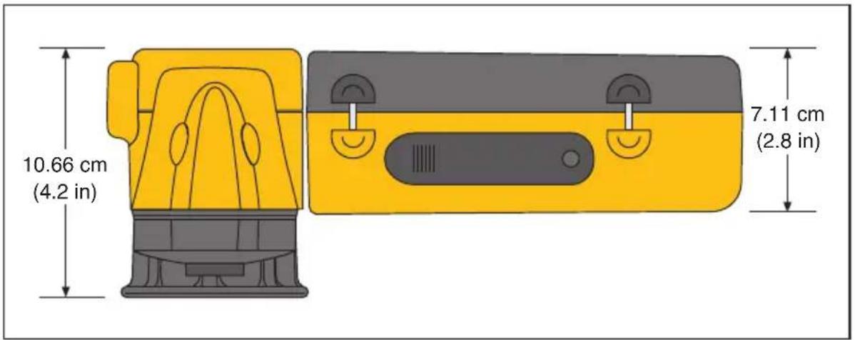
text_image
10.66 cm (4.2 in) 7.11 cm (2.8 in)Figure D-1. Camera Dimensions
eii019.eps
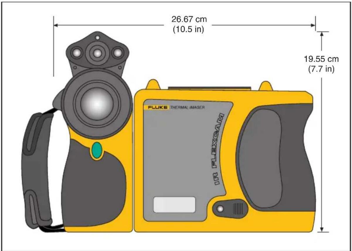
text_image
26.67 cm (10.5 in) 19.55 cm (7.7 in) FLUKE THERMAL IMAGER IR FLEXOAMFigure D-2. Camera Dimensions - Height and Width
eii020.eps
Appendix E
Resources and References
Level 1 Thermography
The Level 1 thermography class is a good start to learn all the necessary skills for the thermography test field.
Level 1 Training Overview
• In a Level I class, participants will:
- Learn to think thermally
- Learn about basic heat transfer theory
• Discover how to successfully use an infrared detector (camera)
• Find out how to inspect electrical and mechanical equipment
- Learn how to analyze building and roof systems using an infrared sensor
- Successfully capture images as well as document findings and write reports
- Learn professional tips on marketing thermography to internal or external customers
Setting Up Your Infrared Program
An effective, sustainable thermography program requires more than just an infrared camera. It requires the right camera used by qualified professionals able to consistently provide high-quality data.
Let Fluke Corporation assist you in developing a successful thermography program. For more information on thermography training and/or setting up your infrared program, contact us at www.fluke.com.
Appendix F
Camera Default Settings
Table F-1 shows the default settings for the TiR2, Ti45 and Ti40 models.
Table F-1. Default Settings, TiR2, Ti45 and Ti40 Models
| Setting Ti45 and TiR2 Ti40 | ||
| Camera Info | ||
| Info | Reference Only | |
| Battery | Reference Only | |
| Camera Settings | ||
| Calendar | ||
| Date Current | ||
| Time Current | ||
| Lens | 20-mm/F.8 (initial from factory, subsequent settings are last user-setting even on “reset to factory defaults”) | |
| Calibration Range | -4 °F to 212 °F (initial from factory, subsequent settings are last user-setting even on “reset to factory defaults”) | |
| Power | ||
| Display Brightness | Normal | |
| High Brightness Timeout | 30 seconds | |
| Standby Time Out | 5 min | |
| Standby to Off Time | 10 min | |
| Video Output | Off | |
| Files | ||
| File Prefix IR | ||
| File Sequence | 0 | |
| Auto-Start Notation Wizard | Disabled | n/a |
| Locale | ||
| Temp. Units | F | |
| Language English | ||
| Video Signal | NTSC | |
| Decimal Symbol | Period | |
| Date MM-dd-yy | ||
| Time HH:mm:ss | ||
| Mouse | ||
| Mouse Sensitivity | Fast | |
| Fast Value Changes | Disabled | |
| Save | Reference Only | |
| Browse Images | Reference Only | |
| VLCM | ||
| Enable VLCM | Enabled | |
| IR-Fusion® Level | 100% IR | |
| Full Screen/PIP | PIP | |
| Flash Enabled | Disabled | |
| High Brightness | Enabled | |
| Vivid Color | Enabled | |
| Image Settings | ||
| Display | ||
| Center Point | Disabled | |
| Center Box | Disabled | |
| Hot Cursor | Disabled | n/a |
| Cold Cursor | Disabled | n/a |
| Temp. Scale | Enabled | |
| Auto-Hide Task Bar | Disabled | |
| Onscreen Logo | Disabled | |
| Mouse Temp | Enabled | |
| Zoom Image | 1x | |
| Image Enhancement | Normal | |
| Emissivity | ||
| Emissivity 0.95 | ||
| Back-ground Temp | 68 °F | |
| ...Fixed Image | Disabled | |
| Image Settings | ||
| Color Palette | ||
| Color Palette | Blue-Red | |
| Saturation Colors | Standard | |
| Automatic Adjustment | Disabled | |
| PIC | ||
| Max. Images | 1 | n/a |
| Interval 1sec n/a | ||
| Trigger Manual n/a | ||
| Markers | Reference Only | n/a |
| Color Alarms | ||
| Enable Onscreen Alarm | Disabled | Disabled |
| Temps. Are Inside Specified Range | TRUE | n/a |
| Max Calibration range maximum n/a | ||
| Min Calibration range maximum n/a | ||
| Annotate Images | Reference Only Disabled | |
| Programmable Buttons | ||
| F1 | Centerpoint/box | |
| F2 | PIP | |
| F3 | Laser | |
Table F-2 shows the default settings for the TiR3, TiR4, Ti55 and Ti50 models.
Table F-2. Default Settings, TiR3, TiR4, Ti55 and Ti50 Models
| Setting Ti5 | 5 and TiR4 Ti50 and TiR3 | ||
| Camera Info | |||
| Info | Reference Only | ||
| Battery | Reference Only | ||
| Camera Settings | |||
| Calendar | |||
| Date Current | |||
| Time Current | |||
| Lens 20mm/F | .8 (initial from factory, subsequent settings are last user-setting even on “reset to factory defaults”) | ||
| Calibration Range | -20 °C to 100 °C (-4 °F to 212 °F)Initial from factory, subsequent settings are last user-setting even on “reset to factory defaults”) | ||
| Power | |||
| Display Brightness | Normal | ||
| High Brightness Timeout | 30 seconds | ||
| Standby Time Out | 5 min | ||
| Standby to Off Time | 10 min | ||
| Video Output | Off | ||
| Files | |||
| File Prefix IR | |||
| File Sequence | 0 | ||
| Auto-Start Notation Wizard | Disabled | n/a | |
| Locale | |||
| Temp. Units F | |||
| Language English | |||
| Video Signal NTSC | |||
| Decimal Symbol | Period | ||
| Date MM-dd-yy | |||
| Time HH:mm:ss | |||
| Mouse | |||
| Mouse Sensitivity | Fast | ||
| Fast Value Changes | Disabled | ||
| Save Reference Only | |||
| Browse Images | Reference Only | ||
| IR-Fusion® | |||
| Enable IR-Fusion® | Enabled | ||
| IR-Fusion® Level | 100% IR | ||
| Full Screen/PIP | PIP | ||
| Flash Enabled | Disabled | ||
| High Brightness | Enabled | ||
| Vivid Color | Enabled | ||
| Image Settings | |||
| Display | |||
| Center Point | Disabled | ||
| Center Box | Disabled | ||
| Hot Cursor | Disabled n/a | ||
| Cold Cursor | Disabled n/a | ||
| Temp. Scale | Enabled | ||
| Auto-Hide Task Bar | Disabled | ||
| Onscreen Logo | Disabled | ||
| Image Settings | |||
| Mouse Temp | Enabled | ||
| Zoom Image | 1x | ||
| Image Enhancement | Off | ||
| Emissivity | |||
| Emissivity 0.95 | |||
| Background Temp | 68 °F | ||
| Fixed Image | Disabled | ||
| Color Palette | |||
| Color Palette | Blue-Red | ||
| Saturation Colors | Standard | ||
| Automatic Adjustment | Disabled | ||
| PIC | |||
| Max. Images | 1 | n/a | |
| Interval 1sec n/a | |||
| Trigger Manual n/a | |||
| Markers | Reference Only | n/a | |
| Color Alarms | |||
| Enable Onscreen Alarm | Disabled | ||
| Temps. Are Inside Specified Range | TRUE | ||
| Max Calibration range maximum | |||
| Min Calibration range minimum | |||
| Annotate Images | Reference Only Disabled | ||
| Programmable Buttons | |||
| F1 | Centerpoint/box | ||
| F2 | PIP | ||
| F3 | Laser | ||
—A—
analysis area, 2-9
analysis point, 2-9
annotations. 2-10, 4-9
add new annotation item. 4-11
adding to saved images, 4-9
auto-annotate, 4-11
auto-annotation function. 4-11
delete, change, or add new category, 4-10
smartview annotations lists, 4-12
area markers. See user-defined display
screen temperature markers
auxiliary power port. See camera overview
—B—
background temperature, 2-8, 4-1
fixed image function, 4-2
setting, 4-1
batteries
camera and battery info. 8-2
charging, 8-3
conserving power, 8-5
disposal, 1-4
inserting, 1-6
recalibrating, 8-4
brightness, 2-10, 6-1
brightness and color controls, 5-4
browse image arrows, 2-8
browse images. 2-10, 3-1
browse thumbnails, 2-10, 5-7
—C—
calibration range. See temperature calibration range
camera and battery information
view battery info, 8-3
view camera info, 8-2
camera overview
camera parts, 2-2
parts descriptions, 2-4
camera settings
restore factory settings, 6-7
save and reload, 6-6
capture image, 1-10. See save image mode and saving images
center box temperatures, 2-9
centerpoint temperature, 2-8
centerpoint/centerbox, 2-10
charging batteries, 8-4
cleaning
camera body, 8-1
display screen, 8-1
lenses, 8-1
cold cursor temperature, 2-9
color alarms, 5-8
color controls, 5-4
color palette, 4-2. See
adjust temperature span, 4-3
changing, 4-2
hiding, 6-2
compactflash memory card
inserting, 1-8, 2-14
removing,2-14
conserving battery power, 8-5
customer service, B-3
—D—
date, 2-8
changing, 6-4
changing format, 6-5
display screen, 2-6
adjusting brightness, 6-1
descriptions, 2-8
hiding color palette, 6-2
hiding task bar, 6-2
temperature markers, 4-7
user-defined temperature markers, 7-4
DSP version, B-4. See camera and battery information
—E—
electronic zoom, 2-10, 3-3
emissivity, 2-8
fixed image function, 4-2
setting value, 4-1
—F—
factory settings. See default settings
file naming. See naming image files
fixed image function
disabling, 4-2
enabling, 4-2
flash, 5-5
enable, 5-5
focus, 1-8, 5-2
full screen view, 2-11, 5-4
fusion blend level, 5-3
adjusting, 5-3
dialog box, 2-9
—G—
glossary, A-1
—H—
hot cursor temperature, 2-9
-|-
image
browse image, 3-1
browse thumbnails, 5-7
file naming, 6-7
pause, 3-1
save, 3-1
image alignment, 5-1
image enhancement, 2-11, 7-1
adjusting level, 7-1
image name, 2-8
infrared lens. See camera overview
infrared program
setting up, E-1
internal recalibration, 7-7
inventory checklist, 1-4
—L—
laser pointer, 2-11, 5-7
safety information, 1-3
lens
changing selection, 6-3
using other lenses, 8-2
level. See level and span
level and span, 1-9, 2-8, 4-3
setting arbitrary fixed temperature, 4-4
setting temperature, auto, 4-4
setting temperature, manual, 4-3
level and span button. See camera overview
—M—
marker toolbar, 2-10, See display screen,
user-defined temperature markers
memory card. See compactflash memory card
menus, 2-12
display screen options, 2-12
model number. See camera and battery information
mouse pointer and temperature, 2-8
MSP version, B-4, See camera and battery information
—N—
naming image files, 6-7
changing name prefix, 6-7
resetting name sequence number, 6-9
notes. See annotations
-0
OCA version, B-4. See camera and battery information off button. See camera overview on button. See camera overview onscreen logo, 4-7
—P—
palette saturation colors, 4-5
enabling/disabling, 4-6
palette visible, 2-10
part number, B-4
pause image mode, 3-1
PIC. See programmable image capture
picture-in-picture view, 2-9, 2-11, 5-4
power source indicator, 2-8
power switch. See camera overview
programmable functions, 2-10
programmable image capture (PIC), 7-1
manual trigger, 7-2
start sequence. 2-11
stop sequence, 2-11
temperature trigger. 7-2
—R—
record sequence of several images. See programmable image capture recording control images, 5-6 reset switch. See camera overview
—s—
safety information, 1-2
saturation colors. See palette saturation colors
save image mode
delete all saved images, 3-3
delete saved image, 3-2
view saved image, 3-2
view saved image info, 3-4
scan target mode, 3-1
sequence number. See naming image files
serial number, B-4. See camera and battery information
smartview software. 1-11. 4-12
span. See level and span
spot temperatures. See display screen, user-defined temperature markers, See display screen, temperature markers
standby mode, 8-5
start sequence, 2-11. See programmable image capture
stop sequence, 2-11. See programmable image capture
—T—
temperature calibration range, 6-3 setting, 6-3
temperature markers. See display screen, temperature markers
temperature units, 2-8 setting, 6-3
thumbnail browser, 5-7
time,2-8
changing,6-5
changing format, 6-5
torch control, 2-10, 5-5
training
thermography,E-1
trigger button, 2-5
troubleshooting, B-1
-U-
unpacking, 1-4
user-defined temperature markers. See display screen, user-defined temperature markers
—V—
video output
enable/disable,6-9
select NTSC or PAL, 6-9
video port. See camera overview
visible light camera module (VLCM), 2-1 enabling/disabling, 5-1
visible light flash, 5-5
visible light lens. See camera overview
vivid color. See brightness and color controls
—z—
zoom. See electronic zoom