
51269 - Cap KENMORE - Free user manual and instructions
Find the device manual for free 51269 KENMORE in PDF.

| Product Type | Range Hood |
| Brand | Kenmore |
| Model | 51269 (also fits models 51262, 51263, 51264) |
| Color Options | White, Stainless Steel, Biscuit, Black |
| Fan Speeds | 2 speeds: Low (I) and High (II) |
| Light Levels | 2 intensities: Low (I) and High (II) |
| Light Bulb Type | Shielded Halogen, 120V, 50W max, GU10 base (2 bulbs included) |
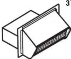
| Duct Size Options | 3-1/4" x 10" rectangular or 7" round |
| Installation System | EZ1 one-person installation or standard installation |
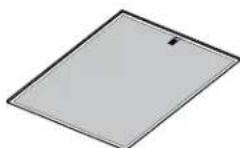
| Filter Type | Aluminum mesh grease filters (2 included, washable) |
| Non-Ducted Option | Yes, requires non-ducted recirculation filters (sold separately) |
| Motor | Permanently lubricated, low noise |
| Warranty | 1 year parts and labor; 30 days on painted/bright metal parts |
| Cleaning | Filters washable in dishwasher or hot water/mild detergent; hood surfaces use mild soap |
| Hood Material | Painted or stainless steel (depending on color option) |
| Electrical Rating | 120V, 60Hz (typical; based on bulb specifications) |
| Equivalent Duct Length | Up to 35 ft for 7" round duct (80% airflow) |
| Optional Accessories | Non-ducted filters, 7" round damper, replacement bulbs |
| Country of Use | United States |
Frequently Asked Questions - 51269 KENMORE
User questions about 51269 KENMORE
0 question about this device. Answer the ones you know or ask your own.
Ask a new question about this device
Download the instructions for your Cap in PDF format for free! Find your manual 51269 - KENMORE and take your electronic device back in hand. On this page are published all the documents necessary for the use of your device. 51269 by KENMORE.
USER MANUAL 51269 KENMORE
Use & Care / Installation Manual
READ AND SAVE THESE INSTRUCTIONS
TABLE OF CONTENTS
SECTION ......PAGE
Warranty 2
Safety Instructions 3
Operation.... 4
Cleaning 4
Parts Included With Hood 5
Parts Not Included With Hood .... 5
Tools Needed 5
Equivalent Duct Length Chart 6
Install Ductwork 7
Prepare The Hood 7-9
Prepare The Hood Location 10-13
EZ1 One-Person Installation 10-11
Install The Hood (EZ-1 Brackets) 12
Standard Installation (without EZ1 Brackets) 13
Install The Hood (Standard Installation) 13
Connect The Wiring 14
Install The Light Bulbs 15
Install The Filters 15
Service Parts 16
KENMORE LIMITED WARRANTY
WITH PROOF OF SALE, the following warranty coverage applies when this appliance is correctly installed, operated and maintained according to all supplied instructions.
FOR ONE YEAR from the date of sale this appliance is warranted against defects in material or workmanship. A defective appliance will receive free repair or replacement at option of seller. This ONE YEAR coverage does not apply to the finish of any painted or bright metal part.
FOR THIRTY DAYS from the date of sale, any painted or bright metal part of this product will be replaced free of charge if its fi nish is defective in material or workmanship.
For warranty coverage details to obtain free repair or replacement, visit the web page: www.kenmore.com/warranty
All warranty coverage is void if this product is ever used for other than private household purposes.
This warranty covers ONLY defects in material and workmanship, and will NOT pay for:
-
Expendable items that can wear out from normal use, including but not limited to filters, belts, bags or screw-in base light bulbs.
-
A service technician to clean or maintain this appliance, or to instruct the user in correct appliance installation, operation and maintenance.
-
Service calls to correct appliance installation not performed by Sears authorized service agents, or to repair problems with house fuses, circuit breakers, house wiring, and plumbing or gas supply systems resulting from such installation.
-
Damage to or failure of this appliance resulting from installation not performed by Sears authorized service agents, including installation that was not in accord with electrical, gas or plumbing codes.
KENMORE LIMITED WARRANTY
- Damage to or failure of this appliance, including discoloration or surface rust, if it is not correctly operated and maintained according to all supplied instructions.
- Damage to or failure of this appliance, including discoloration or surface rust, resulting from accident, alteration, abuse, misuse or use for other than its intended purpose.
- Damage to or failure of this appliance, including discoloration or surface rust, caused by the use of detergents, cleaners, chemicals or utensils other than those recommended in all instructions supplied with the product.
- Damage to or failure of parts or systems resulting from unauthorized modifications made to this appliance.
- Service to an appliance if the model and serial plate is missing, altered, or cannot easily be determined to have the appropriate certification logo.
Disclaimer of implied warranties; limitation of remedies
Customer's sole and exclusive remedy under this limited warranty shall be product repair or replacement as provided herein. Implied warranties, including warranties of merchantability or fitness for a particular purpose, are limited to one year for the range hood and thirty days for painted or bright metal parts, or the shortest period allowed by law. Seller shall not be liable for incidental or consequential damages. Some states and provinces do not allow the exclusion or limitation of incidental or consequential damages, or limitation on the duration of implied warranties of merchantability or fitness, so these exclusions or limitations may not apply to you.
This warranty applies only while this appliance is used in the United States.
This warranty gives you specific legal rights, and you may also have other rights which vary from state to state.
Sears Brands Management Corporation,
Hoffman Estates, IL 60179
SAFETY INSTRUCTIONS
- Use this unit only in the manner intended by the manufacturer. If you have questions, contact the manufacturer at the address listed in the warranty.
- Before servicing or cleaning unit, switch power off at service panel and lock the service disconnecting means to prevent power from being switched on accidentally. When the service disconnecting means cannot be locked, securely fasten a prominent warning device, such as a tag, to the service panel.
- Installation work and electrical wiring must be done by a qualified person(s) in accordance with all applicable codes and standards, including fi re-rated codes and standards.
- Sufficient air is needed for proper combustion and exhausting of gases through the fl ue (chimney) of fuel burning equipment to prevent backdrafting. Follow the heating equipment manufacturer's guideline and safety standards such as those published by the National Fire Protection Association (NFPA), and the American Society for Heating, Refrigeration and Air Conditioning Engineers (ASHRAE), and the local code authorities.
- When cutting or drilling into wall or ceiling, do not damage electrical wiring and other hidden utilities.
- To reduce the risk of fire or electric shock, do not use this range hood with an additional speed control device.
- Ducted fans must always be vented to the outdoors.
- To reduce the risk of fire, use only metal ductwork.
- This unit must be grounded.
TO REDUCE THE RISK OF A RANGE TOP GREASE FIRE:
- Never leave surface units unattended at high settings. Boilovers cause smoking and greasy spillovers that may ignite. Heat oils slowly on low or medium settings.
- Always turn hood ON when cooking at high heat or when cooking fl aming foods.
- Clean ventilating fans frequently. Grease should not be allowed to accumulate on fan or filter.
- Use proper pan size. Always use cookware appropriate for the size of the surface element.
WARNING
TO REDUCE THE RISK OF INJURY TO PERSONS IN THE EVENT OF A RANGE TOP GREASE FIRE, OBSERVE THE FOLLOWING:\*
- SMOTHER FLAMES with a close-fitting lid, cookie sheet, or metal tray, then turn off the burner. BE CAREFUL TO PREVENT BURNS. If the flames do not go out immediately, EVACUATE AND CALL THE FIRE DEPARTMENT.
- NEVER PICK UP A FLAMING PAN - You may be burned.
- DO NOT USE WATER, including wet dishcloths or towels - a violent steam explosion will result.
- Use an extinguisher ONLY if:
A. You know you have a Class ABC extinguisher and you already know how to operate it.
B. The fire is small and contained in the area where it started.
C. The fire department is being called.
D. You can fight the fire with your back to an exit.
* Based on "Kitchen Fire safety Tips" published by NFPA.
CAUTION
- For general ventilating use only. Do not use to exhaust hazardous or explosive materials and vapors.
- To avoid motor bearing damage and noisy and/or unbalanced impellers, keep drywall spray, construction dust, etc. off power unit.
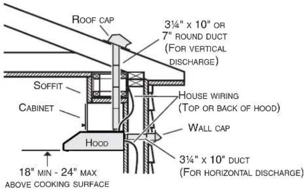
- For best capture of cooking impurities, your range hood should be mounted so that the top of the hood is 18-24" above the cooking surface.
- Use only with range hood cord-connection kits that have been investigated and found acceptable for use with this model range hood.
- Please read specification label on product for further information and requirements.
NOTE
If hood is to be installed Non-Ducted: Purchase non-ducted fi liters and attach them to the aluminum mesh fi liters.
"Non-ducted Filters" available by calling 1-844-553-6667
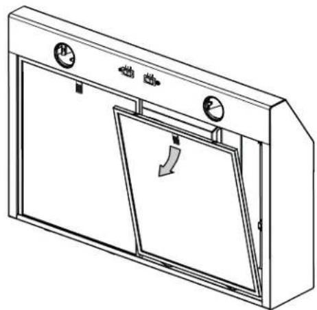
OPERATION
FAN
SWITCH
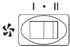
LIGHT
SWITCH
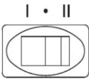

Fan
This rocker switch (on the left) controls the fan. See below:
I Turns fan on to LOW speed.
- Turns fan OFF.
II Turns fan on to HIGH speed.
Light
This rocker switch (on the right) controls the light. See below:
| Turns light on to LOW intensity.
- Turns light OFF.
II Turns light on to HIGH intensity.
CLEANING

WARNING: To reduce the risk of electric shock, disconnect from power supply before cleaning.
Aluminum mesh fi Iters
Clean frequently using hot water and a mild detergent or in your dishwasher. The aluminum mesh filter should be washed approximately every month depending on the amount of usage. Wash more often if your cooking style generates greater grease - like frying foods or wok cooking.
Non-ducted recirculation fi Iters
(available separately - see page 5)
The non-ducted recirculation fl Iters should be changed every 3 to 6 months. Replace more often if your cooking style generates extra grease, such as frying and wok cooking. Refer to installation instructions included with non-ducted recirculation fl Iters.
Painted hood surfaces
Clean with warm water and mild detergent only. If discoloration occurs, use a fi nish polish such as automotive polish. (DO NOT use rough abrasive cleaner or porcelain cleaner.)
Stainless steel hood surfaces
Do:
- Regularly wash with clean cloth or rag soaked with warm water and mild soap or liquid dish detergent.
• Always clean in the direction of original polish lines.
• Always rinse well with clear water (2 or 3 times) after cleaning. Wipe dry completely. - You may also use a specialized household stainless steel cleaner.
Don't:
- Use any steel or stainless steel wool or any other scrapers to remove stubborn dirt.
- Use any harsh or abrasive cleansers.
- Allow dirt to accumulate.
- Let plaster dust or any other construction residues reach the hood. During construction/renovation, cover the range hood to make sure no dust sticks to the stainless steel surface.
Avoid when choosing a detergent:
- Any cleaners that contain bleach will attack stainless steel.
• Any products containing: chloride, fluoride, iodide, bromide will deteriorate surfaces rapidly. - Any combustible products used for cleaning such as acetone, alcohol, ether, benzol, etc., are highly explosive and should never be used close to a range.
Fan assembly
The fan blade should be cleaned frequently. Use a clean cloth soaked with warm detergent solution.
The motor is permanently lubricated and never needs oiling. If the motor bearings make excessive or unusual noise, replace the motor with the exact service motor. The fan blade should also be replaced.
PARTS INCLUDED WITH HOOD
Aluminum Grease Filters (2 per hood)
3 ^1/4 " x 10"
Damper / Duct Connector

7" Round Duct Connector
EZ-1 One person Installation Kit (including template for ducting, printed both sides, and installation brackets)
Parts Bag
(4 no. 8-18 x 1/2" metal screws,
6 no. 8 x 5/8" round head wood screws,
6 no. 8 x 1/2" countersunk wood screws,
1 bulb suction cup tool)
PARTS NOT INCLUDED WITH HOOD
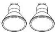
Shielded Halogen Bulbs
(120 V, 50 W max., MR16 or
PAR16 with GU10 base)
(2 per hood)
Part No. SV05921
OPTIONAL PARTS (purchase separately)
Non-Ducted Recirculation Filters
(Non-ducted hoods only)
(2 per hood)
Part No. S97020466

7-inch Round Damper
(For use with 7-inch Round Duct)
Part No. 59183
"Parts Not Included With Hood" available by calling 1-844-553-6667
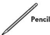
TOOLS NEEDED FOR HOOD INSTALLATION
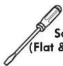
Screwdriver
(Flat & Phillips no. 2)

Drill
(with 1/8" and
7/64" drill bits,
and 1½" hole saw)

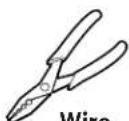
Long Nose
Pliers
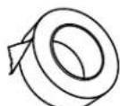
Metal Foil
Duct Tape

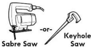

Sheet Metal
Shears
Stripper
EQUIVALENT DUCT LENGTH CHART
Kenmore range hoods are designed to perform efficiently when attached to long runs of duct. As a point of reference, this hood will function at approximately 80% of its rated air flow when 35 equivalent feet of 7" round ductwork is attached. Use this chart to calculate the equivalent duct length of your system.

Straight Duct 3¼-in. x 10-in. x 2-ft. long Equivalent length 2 ft.
Straight Duct 7-in. round x 2-ft. long Equivalent length 2 ft.
7-in. Round Elbow Equivalent length 8 ft.
3¼-in. x 10-in. to 7-in. Round Transition Equivalent length 5.5 ft.
3¼-in. x 10-in. Right-angle Elbow Equivalent length 8.5 ft.
3½-in. x 10-in. Right-angle Flat Elbow Equivalent length 24 ft.

natural_image
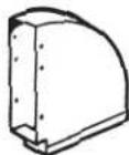
Technical line drawing of a mechanical component with no visible text or symbols3¼-in. x 10-in. Right-angle Short Eave Elbow Equivalent length 15 ft.
natural_image
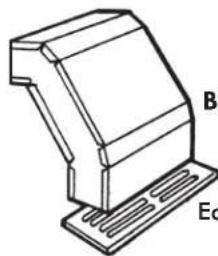
Technical line drawing of a mechanical component with labeled parts B and Ec (no text or symbols beyond labels)B3¼-in. x 10-in. Right-angle Long Eave Elbow Equivalent length 15 ft.
7-in. Round Wall Cap Equivalent length 34 ft. (6-ft. w/o damper)
natural_image
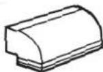
Isometric line drawing of a rectangular electronic component with a flanged top and side gap (no text or symbols)3¼-in. x 10-in. Wall Cap Equivalent length 45 ft. (7-ft. w/o damper)
natural_image
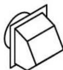
Simple line drawing of a 3D geometric object on a plane, no text or symbols presentRoof Cap (accepts 7-in. round or 3½-in. x 10-in. duct) Equivalent length 30 ft. (7-ft. w/o damper)
"Ducting Accessories" available by calling 1-844-553-6667
INSTALL DUCTWORK (DUCTED INSTALLATION ONLY)
- Determine whether hood will discharge vertically (3 ^1/4 x 10" or 7" Round) or horizontally (3 ^1/4 x 10" only).
- Run ductwork between the hood location and a roof cap or wall cap.
- Choose a straight, short duct run to allow the hood to perform most efficiently. Long duct runs, elbows and transitions will reduce the performance of the hood. Use as few of them as possible. When possible, use at least 2 foot straight runs before any turns. Larger ductwork may be required for best performance with longer duct runs.
- Install wall cap or roof cap (sold separately). Connect metal ductwork to cap and work back towards the hood location. Use 2" metal foil duct tape to seal the joints between ductwork sections.
NOTE: Distances over 24" are at the installer and user discretion.
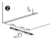
PREPARE THE HOOD
- If present, remove all protective polyfi lm from the hood and/or parts. Using the tab, remove the Aluminum Mesh Filters from the hood by pulling down the tab and tilting fi lters out.
- Remove the EZ1 brackets from inside the hood by cutting off the tie wrap. Remove both screws holding damper assembly to hood. Remove parts bag (captured behind the damper assembly). Remove damper assembly from inside the hood and keep the screws for further use.
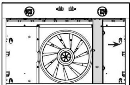
- Remove the wiring cover (shaded part on illustration beside) by sliding it out from the hood and set it aside.
natural_image
Line drawing of a cabinet with doors and gauges, showing a directional arrow (no text or symbols)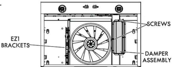
natural_image
Technical diagram of a mechanical or electrical component with a central wheel and side-mounted ports (no text or symbols visible)-
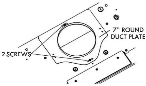
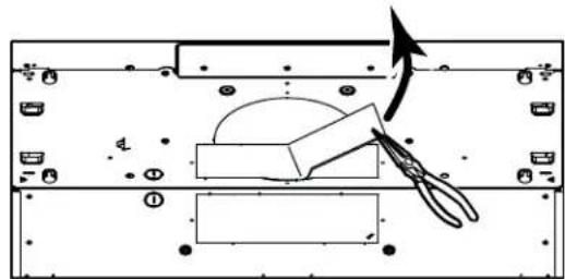
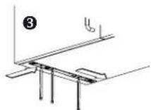
Remove 7" Round Duct Plate from top/back of hood (see illustration beside).
-
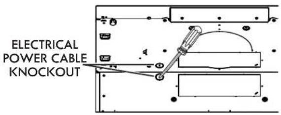
Remove Electrical Power Cable Knockout from top (vertical exhaust) or back (horizontal exhaust) of hood. Install an appropriate strain relief, 1/2" diameter (not included).
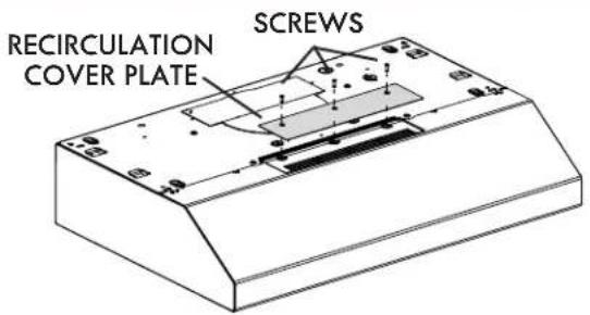
NON-DUCTED INSTALLATIONS ONLY
- Remove 3 screws retaining the recirculation cover plate (shaded part in illustration beside) to the hood. Discard this plate with its screws.
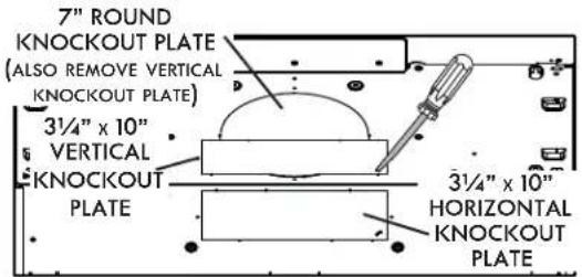
DUCTED INSTALLATIONS ONLY
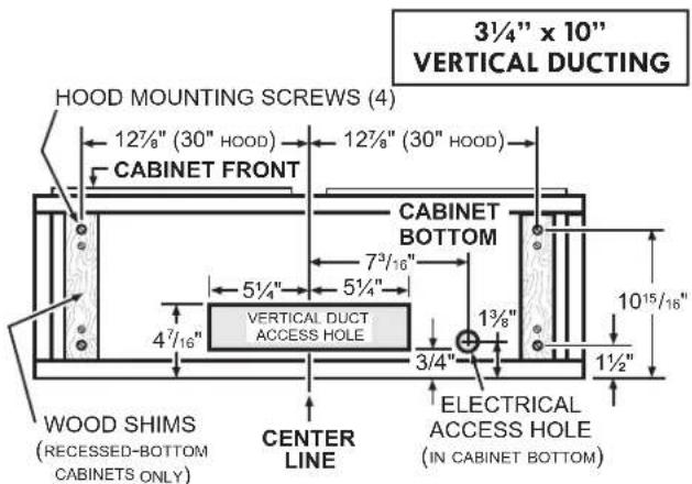
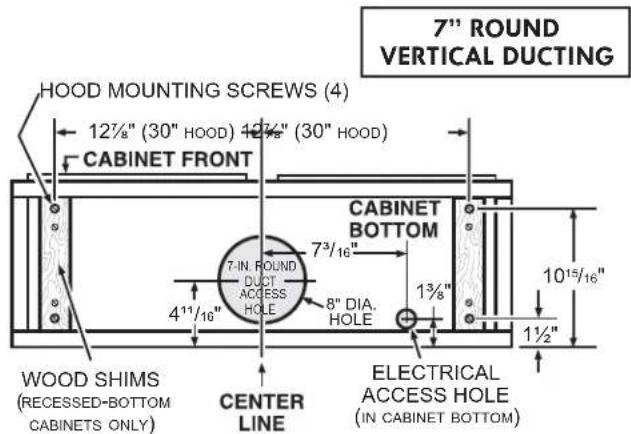
- Remove 3½" x 10" vertical, 3½" x 10" horizontal, or 7-inch round knockout plate as appropriate for your ducting method (see FIGURES 1 A and 1 B).
FIGURE 1 A FIGURE 1 B
- Attach 3 ^1/4 " x 10" Damper Assembly on top OR back of hood (if using 3 ^1/4 " x 10" duct; shaded part in FIGURE 2 A) or 7" Round Duct Plate (if using 7-inch round duct, FIGURE 3) over the knockout opening. When installed, the 3 ^1/4 " x 10" damper assembly must open as shown in FIGURE 2 B.
FIGURE 2 A

FIGURE 2 B

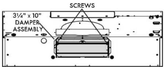
NOTE: To accommodate off-center ductwork, the 7" round duct plate can be installed up to 1/2" on either side of the hood center.
TIP: Insert a small length of duct over the 3½" x 10" damper assembly (for rectangular ducting) or 7" round (for round ducting) and seal the joint using aluminum foil duct tape to ease connection with the house ductwork.
PREPARE THE HOOD LOCATION
NOTE: Before starting installation, read all the steps of these instructions.
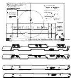
Use the illustration beside to identify your kitchen cabinet type.
This manual covers 2 kinds of installation: the standard (without EZ1 brackets) and the EZ1 one-person installation system (using included template and brackets). For the standard installation, go to page 13.
FRAMED CABINET FRAMELESS CABINET
natural_image
Two technical line drawings of a cabinet or enclosure with no text, numbers, or symbols present.EZ1 One-person installation system
EZ1 installation is designed for use with kitchen cabinets that have the same width designation as the range hood width. If the cabinet is greater than 1/2" wider than the range hood width, please use the standard installation method.
-
Use the proper template for vertical OR horizontal discharge (included) for placement of ductwork and electrical cutout in cabinet or wall. For a non-ducted installation, DO NOT cut a duct access hole, only cut the hole for electrical wiring. If replacing a hood and plan to use the existing duct and electrical, steps 2 to 5 may not be necessary. If so, skip to step 6.
-
Measure and mark the hood center line on cabinet bottom.
-
Align the center line on template with the hood center line marked on the bottom of the cabinet, placing the edge (where indicated) of the template against back wall. When using with framed cabinet for vertical exhaust installation, fold over rear edge of template equal to the depth of the cabinet frame at the wall (use graduations on template, C locations on template). Tape the template in place.
NOTE: When facing the installation, A and B (on template) must be at right.

-
Drill a 1/8" dia. pilot hole for house wiring, at A location on template.
-
Use a sharp pencil or 1/8" drill bit to mark the locations for the appropriate duct access holes (16 locations for 7" round duct, or 4 corner locations for rectangular duct). Remove the template.
-
Draw the border for the exhaust ducting by linking its marks (16 for round duct and 4 for rectangular duct), then cut the opening in the cabinet bottom (vertical exhaust) or in the wall (horizontal exhaust). Drill the house wiring hole by using a 1½" hole saw centered with the pilot hole previously made in 4.
-
Install the proper installation brackets according to the type of cabinet (framed or frameless). See below.
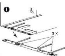
FRAMED CABINET
Refer to the marking on the brackets to determine the correct installation side and orientation.
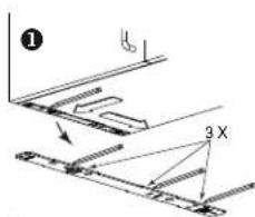
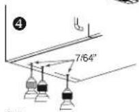
① Mate the corresponding bracket to the cabinet side frame, while placing rear end of bracket against the wall. Use a pencil to mark 3 holes (there are 6 holes but only 3 are necessary).
② Remove the bracket. Using a 7/64" drill bit, drill 3 holes where marked.
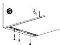
③ Assemble the bracket to the side frame using a Phillips screwdriver and 3 provided no. 8 x 5/8" wood screws. Repeat for the other side frame.
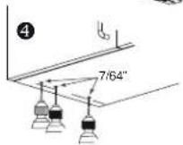
FRAMELESS CABINET
Refer to the marking on the brackets to determine the correct installation side and orientation.
① Align the corresponding bracket to the cabinet side, while placing rear end of bracket against the wall. Draw a line on the outer edge of the bracket (as shown).
② Slide the bracket towards the center of cabinet and align the outside edge of the bracket with the marked line, keeping the rear end edge leaning on the wall.
③ Use a pencil to mark 3 holes.
④ Remove the bracket. Using a 7/64" drill bit, drill 3 holes where marked.
⑤ Assemble the bracket to the cabinet bottom using a Phillips screwdriver and 3 provided countersunk wood screws. Repeat for the other cabinet side .
1
natural_image
Technical line drawing of a mechanical assembly with no visible text or symbols2
3
natural_image
Technical line drawing of a structural assembly with beams and supports (no text or symbols)
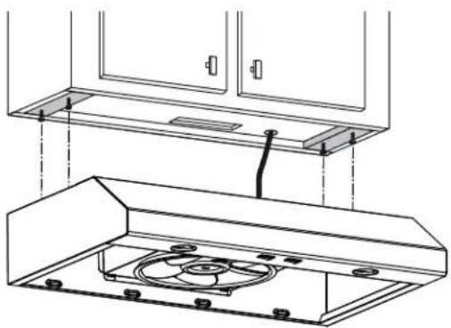
Install the hood (EZ1 brackets)
NOTE: The following procedure applies to both framed or frameless cabinet installations.
- Run house power cable between service panel and hood location.
- There are 2 pairs of recessed holes on each side of the top of the hood (on rear: A and B, on front C and D on illustration beside); these holes allow the range hood to hang on the brackets (previously installed).
HORIZONTAL EXHAUST INSTALLATION ONLY
-
Temporarily hang the hood on the brackets using its 2 recessed REAR HOLES (A and B). While holding the hood, run the house power cable into the hood through the strain relief previously installed in step 5 on page 8.
-
Unhook the rear holes from the brackets and hang the hood using its 2 recessed FRONT HOLES (C and D). While holding the hood, attach the power cable to the hood using the strain relief.
VERTICAL EXHAUST INSTALLATION ONLY
- Hang the hood on the brackets using the 2 recessed FRONT HOLES (C and D). While holding the hood, run the house power cable into the hood through the strain relief previously installed in step 5 on page 8. Attach power cable to the hood.

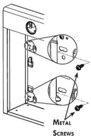
DUCTED INSTALLATIONS ONLY
-
Connect the ductwork to the hood and use metal foil duct tape to make joints secure and air-tight. Make sure the damper assembly (or round duct plate) enters the ductwork and that the damper opens and closes freely.
-
For framed cabinet, secure the hood to the EZ1 brackets using 4 no. 8-18 x 1/2" metal screws (screws included in parts bag). Insert 2 screws per side, in the slots (as shown in inset on illustration beside).
-
For frameless cabinet, secure the hood to the cabinet using 4 no. 8 x 5/8" round head wood screws (screws included in parts bag). Insert 2 screws per side, in the slots (as shown in inset on illustration beside).
-
For framed cabinet, secure the hood to the EZ1 brackets using 4 no. 8-18 x 1/2" metal screws (screws included in parts bag). Insert 2 screws per side, in the slots (as shown in inset on illustration beside).
- For frameless cabinet, secure the hood to the cabinet using 4 no. 8 x 5/8" round head wood screws (screws included in parts bag). Insert 2 screws per side, in the slots (as shown in inset on illustration beside).
FRAMED CABINET FRAMELESS CABINET

Standard Installation (without EZ1 brackets)
- Use these diagrams for proper placement of ductwork and electrical cutout in cabinet or wall.
For a non-ducted installation, DO NOT cut a duct access hole, only cut the hole for electrical wiring
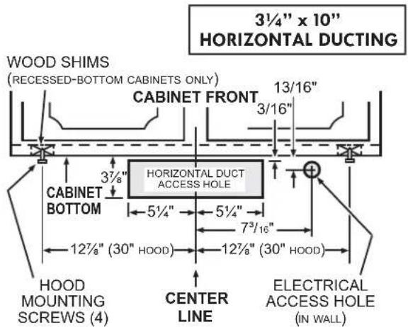
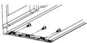
- Install part-way four (4) ROUND HEAD no. 8 x 5/8" mounting screws into shims/cabinet, according to the proper diagram above. (Mounting screws are included in parts bag, but wood shims and shim mounting screws are not included).
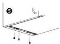
Install the Hood (Standard Installation)
NOTE: Two installers are recommended because of the weight of this hood.
- Run house power cable between service panel and hood location. Run the house power cable into the hood through the strain relief previously installed in step 5 on page 8.
- Hang hood from (4) mounting screws previously installed. Slide hood back towards wall until mounting screw heads are engaged in narrow end of keyhole slots in top of hood. Tighten screws securely. Attach power cable to the hood using the strain relief.
natural_image
Technical line drawing of a cabinet with an open hood and internal components (no text or symbols)DUCTED INSTALLATIONS ONLY
- Connect the ductwork to the hood and use metal foil duct tape to make joints secure and air-tight. Make sure the damper assembly (or round duct plate) enters the ductwork and that the damper opens and closes freely.
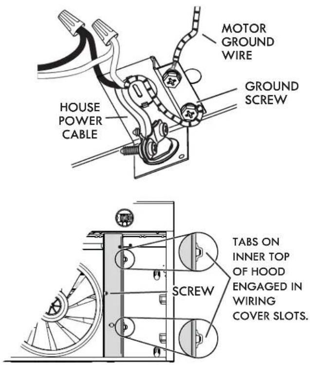
CONNECT THE WIRING

WARNING: Risk of electric shock. Electrical wiring must be done by qualified personnel in accordance with all applicable codes and standards. Before connecting wires, switch power off at service panel and lock service disconnecting means to prevent power from being switched on accidentally.
-
Connect House Power Cable to range hood wiring: BLACK to BLACK, WHITE to WHITE and GREEN or bare wire under GREEN ground screw.
-
Reinstall wiring cover and attach it to the hood using its retaining screw.

CAUTION: Ensure both tabs on inner top of hood are engaged in their corresponding slots in wiring cover. Also, take care not to pinch wires while reinstalling wiring cover.
INSTALL THE LIGHT BULBS
This range hood requires two shielded Halogen Bulbs (120 V, 50 W max., MR16 or PAR16 with GU10 base).

WARNING: Do not touch lamps during or soon after operation. Burns may occur. In order to prevent the risk of personal injury, only install shielded halogen lamps. Also, never install a cool beam, a dichroic lamp, a lamp not suitable for use in recessed luminaires or identified for use in enclosed fixtures.
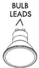
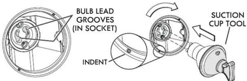
-
Align the bulb leads with the small indentations located on the border of the lamp location on hood (see inset above), then install the bulbs by placing the bulb leads into their grooves in the socket.
-
Gently push upwards and turn clockwise until secured.
NOTE: The Suction Cup Tool (included with hood) can be used to install and remove light bulbs. Press suction cup tool on bulb and rotate counterclockwise to remove bulb or clockwise to install bulb.

CAUTION: Most GU10 LED replacement bulbs commonly found in the market are not designed for use in a cooking environment and might not perform as advertised. Their usage with this product is not recommended.
INSTALL THE FILTERS
Ducted Installation Only:
Re-install grease filters removed in step 1 on page 7, under "Prepare the Hood".
Non-ducted Installation Only:
Purchase two non-ducted filters (see part number in Service parts list). Attach the non-ducted filters following instructions packed with the non-ducted filters.
"Non-ducted Filters" available by calling 1-844-553-6667
SERVICE PARTS

| KEY NO. | PART NO. DESCRIPTION | QUANTITY | ||||
| 51262 | 51263 | 51264 | 51269 | |||
| 1 | S97020030 R | ECIRCULATION COVER PLATE, WHITE (INCLUDING SCREWS) | 1 | |||
| S97020031 R | ECIRCULATION COVER PLATE, STAINLESS STEEL (INCL. SCREWS) | 1 | ||||
| S97020471 R | ECIRCULATION COVER PLATE, BISCUIT (INCLUDING SCREWS) | 1 | ||||
| S97020029 R | ECIRCULATION COVER PLATE, BLACK (INCLUDING SCREWS) | 1 | ||||
| 2 SR6 | 80508 7" R | OUND DUCT PLATE (INCLUDING SCREWS) | 1 | 1 | 1 | 1 |
| 3 S97 | 020534 31⁄4" | X 10" DAMPER ASSEMBLY (INCLUDING SCREWS) | 1 | 1 | 1 | 1 |
| 4 | S97020408 B | LOWER MOTOR (INCLUDING 4 SCREWS AND 1 CAPACITOR) | 1 | 1 | 1 | 1 |
| 5 | S97020407 | FANPELLER (INCLUDING ITEM 6) | 1 | 1 | 1 | 1 |
| 6 | SR99420635 | CLIP FOR FANPELLER | 1 | 1 | 1 | 1 |
| 7 | S99010430-002 | GREASE FILTER - OPEN MESH - TYPE C1 (SET OF 2) | 1 | 1 | 1 | 1 |
| 8 | S99030355 | ROCKER SWITCH, WHITE (SET OF 2) | 1 | |||
| S99030367 R | OCKER SWITCH, GREY (SET OF 2) | 1 | ||||
| S99030357 R | OCKER SWITCH, BISCUIT (SET OF 2) | 1 | ||||
| S99030356 | ROCKER SWITCH, BLACK (SET OF 2) | 1 | ||||
| 9 | S97020448 | WIRE HARNESS | 1 | 1 | 1 | 1 |
| * | S98011637 | WIRING COVER | 1 | 1 | 1 | 1 |
| * | S97020292 | PARTS BAG INCLUDING: 4 METAL SCREWS NO. 8-18 x 1/2", 6 ROUND HEAD NO. 8 x 5/8" WOOD SCREWS, 6 NO. 8 x 1/2" COUNTERSUNK SCREWS, 1 SUCTION CUP TOOL | 1 | 1 | 1 | 1 |
| * S97 | 020466 | NON-DUCTED FILTER - TYPE XC (SET OF 2) (NON-DUCTED INSTALLATION ONLY) | 1 | 1 | 1 | 1 |
| * | S99527587 N | ON-DUCTED FILTER CLIP KIT (INCLUDES 4 CLIPS) | 1 | 1 | 1 | 1 |
| * | SV05921 | SHIELDED HALOGEN BULB 50 W, GU10 | 2 | 2 | 2 | 2 |
| * | S97020470 | EASY INSTALL KIT (INCLUDING HARDWARE) | 1 | 1 | 1 | 1 |
Order replacement parts by PART NO. - not by KEY NO.
* Not illustrated
REPLACEMENT PARTS
In order to ensure your unit remains in good working condition, you must use the manufacturer genuine replacement parts only. The manufacturer genuine replacement parts are specially designed for each unit and are manufactured to comply with all the applicable certification standards and maintain a high standard of safety. Any third party replacement part used may cause serious damage and drastically reduce the performance level of your unit, which will result in premature failing. To purchase the genuine replacement parts listed above, call 1-844-553-6667 16
LEA Y CONSERVE ESTAS INSTRUCCIONES
TABLA DE CONTENIDO GARANTÍA
SECCIÓN....PÁGINA
Garantía....17
Sears Brands Management Corporation, Hoff man Estates, Illinois 60179
PREVISTO PARA COCINAR DOMÉSTICO SOLAMENTE.
natural_image
Technical line drawing of a mechanical component with no visible text or symbolsnatural_image
Technical line drawing of a mechanical component with no visible text or symbolsnatural_image
Pure technical line drawing of a 3D connector or housing component (no text or symbols)natural_image
Isometric line drawing of a 3D geometric object with a sloped top surface and a flat base (no text or symbols)natural_image
Line drawing of a cabinet with doors and gauges, showing a directional arrow (no text or symbols)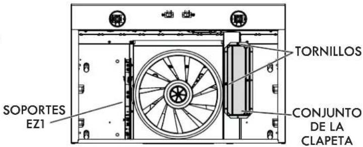

natural_image
Technical diagram of a mechanical assembly with a central wheel and directional arrows (no text or labels)natural_image
Two technical line drawings of a cabinet or enclosure with no text, numbers, or symbols present.1

natural_image
Pure mechanical assembly diagram showing structural components without any text, numbers, or symbols2

3
natural_image
Technical line drawing of a structural panel with mounting holes and beams (no text or symbols)


Instale la campana (Soportes EZ1)
natural_image
Technical line drawing of a kitchen appliance assembly (no text or symbols)| CLAVE N.° | PIEZA N.° DESCRIPCIÓN | CANTIDAD | ||||
| 51262 | 51263 | 51264 | 51269 | |||
| 1 | S97020030 P | LACA DE CUBIERTA DE RECIRCULACIÓN, BLANCA (INCLUYE TORNILLOS) | 1 | |||
| S97020031 P | LACA DE CUBIERTA DE RECIRCULACIÓN, ACERO INOX. (INCL. TORNILLOS) | 1 | ||||
| S97020471 P | LACA DE CUBIERTA DE RECIRCULACIÓN, BIZCOCHO (INCL. TORNILLOS) | 1 | ||||
| S97020029 P | LACA DE CUBIERTA DE RECIRCULACIÓN, NEGRA (INCLUYE TORNILLOS) | 1 | ||||
| 2 SR | 680508 C | ONECTOR DE CONDUCTO REDONDO DE 7" (INCLUYE TORNILLOS) | 1 | 1 | 1 | 1 |
| 3 S9 | 7020534 C | ONJUNTO DE CLAPETA DE 3 14 " x 10" (INCLUYE TORNILLOS) | 1 | 1 | 1 | 1 |
| 4 S9 | 7020408 M | OTOR DEL VENTILADOR IMPELENTE (INCL. 4 TORNILLOS Y 1 CONDENSADOR) | 1 | 1 | 1 | 1 |
| 5 S9 | 7020407 H | ÉLICE (INCLUYE N.° 6) | 1 | 1 | 1 | 1 |
| 6 | SR99420635 | CLIP DE LA HÉLICE | 1 | 1 | 1 | 1 |
| 7 S9 | 9010430-002 F | ILTRO DE GRASA - ESTANDAR - TYPO C1 (JUEGO DE 2) | 1 | 1 | 1 | 1 |
| 8 | S99030355 | INTERRUPTOR OSCILANTE, BLANCO (SJUEGO DE 2) | 1 | |||
| S99030367 I | NTERRUPTOR OSCILANTE, GRIS (JUEGO DE 2) | 1 | ||||
| S99030357 I | NTERRUPTOR OSCILANTE, BIZCOHO (JUEGO DE 2) | 1 | ||||
| S99030356 | INTERRUPTOR OSCILANTE, NEGRO (JUEGO 2) | 1 | ||||
| 9 S9 | 7020448 H | ARNÉS DE HILOS | 1 | 1 | 1 | 1 |
| * | S98011637 | TAPA DE CABLEADOS | 1 | 1 | 1 | 1 |
| * | S97020292 | BOLSA DE PIEZAS, INCLUYE: 4 TORNILLOS PARA METAL N.° 8-18 x 1/2", 6 TORNILLOS DE CABEZA REDONDA PARA MADERA N.° 8 x 9/16", 6 TORNILLOS EMBUTIDOS N.° 8 x 1/2", 1 VENTOSA | 1 | 1 | 1 | 1 |
| * S9 | 7020466 | FILTRO DE RECIRCULACIÓN - TYPO Xc (JUEGO DE 2) (INSTALACIÓN SIN CONDUCTOS ÚNICAMENTE) | 1 | 1 | 1 | 1 |
| * | S99527587 J | UEGO DE SUJETADORES PARA FILTROS DE CARBÓN - INCLUYE 4 SUJETADORES | 1 | 1 | 1 | 1 |
| * | SV05921 | BOMBILLA HALÓGENA CON PANTALLA 50 W, GU10 | 2 | 2 | 2 | 2 |
| * | S97020470 | EQUIPO PARA FÁCIL INSTALACIÓN (INCLUYE TORNILLOS) | 1 | 1 | 1 | 1 |
Customer Care Hotline
To schedule in-home repair service or order replacement parts
- READ AND SAVE THESE INSTRUCTIONS
- TABLE OF CONTENTS
- KENMORE LIMITED WARRANTY
- SAFETY INSTRUCTIONS
- TO REDUCE THE RISK OF A RANGE TOP GREASE FIRE:
- WARNING
- TO REDUCE THE RISK OF INJURY TO PERSONS IN THE EVENT OF A RANGE TOP GREASE FIRE, OBSERVE THE FOLLOWING:\*
- CAUTION
- NOTE
- OPERATION
- Fan
- Light
- CLEANING
- Aluminum mesh fi Iters
- Non-ducted recirculation fi Iters
- Painted hood surfaces
- Stainless steel hood surfaces
- Do:
- Don't:
- Avoid when choosing a detergent:
- Fan assembly
- PARTS INCLUDED WITH HOOD
- Parts Bag
- PARTS NOT INCLUDED WITH HOOD
- TOOLS NEEDED FOR HOOD INSTALLATION
- EQUIVALENT DUCT LENGTH CHART
- INSTALL DUCTWORK (DUCTED INSTALLATION ONLY)
- PREPARE THE HOOD
- NON-DUCTED INSTALLATIONS ONLY
- DUCTED INSTALLATIONS ONLY
- PREPARE THE HOOD LOCATION
- EZ1 One-person installation system
- FRAMED CABINET
- FRAMELESS CABINET
- Install the hood (EZ1 brackets)
- HORIZONTAL EXHAUST INSTALLATION ONLY
- VERTICAL EXHAUST INSTALLATION ONLY
- Standard Installation (without EZ1 brackets)
- Install the Hood (Standard Installation)
- CONNECT THE WIRING
- INSTALL THE LIGHT BULBS
- INSTALL THE FILTERS
- Ducted Installation Only:
- Non-ducted Installation Only:
- SERVICE PARTS
- REPLACEMENT PARTS
- LEA Y CONSERVE ESTAS INSTRUCCIONES
- TABLA DE CONTENIDO GARANTÍA
- SECCIÓN....PÁGINA
- PREVISTO PARA COCINAR DOMÉSTICO SOLAMENTE.
- Instale la campana (Soportes EZ1)
- Customer Care Hotline
Brand : KENMORE
Model : 51269
Category : Cap