
CDC-TI - Tablet ECS - Free user manual and instructions
Find the device manual for free CDC-TI ECS in PDF.

| Product Type | Motherboard |
| Brand | ECS |
| Model | CDC-TI |
| Form Factor | Thin Mini-ITX |
| Dimensions | 170 mm x 170 mm |
| Weight | Approx. 0.5 kg |
| Power Supply | External 19V DC adapter (not included) |
| CPU | Intel Onboard Cedarview (e.g., Atom D2700) |
| Chipset | Intel NM10 Express |
| Memory Support | 2 x DDR3 SO-DIMM slots, up to 4 GB, 1066/800 MHz |
| Expansion Slots | 1 x PCIe x1 (optional), 2 x mini PCIe x1 |
| Storage | 2 x SATA 3.0Gb/s |
| Audio | Realtek ALC662 6-channel HD Audio |
| LAN | Realtek 8111E Gigabit Ethernet |
| Rear I/O Ports | 1x DC-IN, 1x VGA, 1x HDMI, 2x USB 2.0, 1x RJ45, audio jacks (mic + line-out) |
| Internal Headers | USB 2.0, COM, LPT, LVDS, Front Panel, etc. |
| BIOS | AMI UEFI GUI with 32Mb SPI Flash ROM |
| Utilities | Supports ECS eBLU, eDLU, eSF |
| Safety Precautions | Use grounding strap; disconnect power before installation |
| Maintenance | Keep in cool, dry place; clean cooler fan regularly |
Frequently Asked Questions - CDC-TI ECS
User questions about CDC-TI ECS
0 question about this device. Answer the ones you know or ask your own.
Ask a new question about this device
Download the instructions for your Tablet in PDF format for free! Find your manual CDC-TI - ECS and take your electronic device back in hand. On this page are published all the documents necessary for the use of your device. CDC-TI by ECS.
USER MANUAL CDC-TI ECS
This publication, including all photographs, illustrations and software, is protected under international copyright laws, with all rights reserved. Neither this manual, nor any of the material contained herein, may be reproduced without written consent of the author.
Version 1.0A
Disclaimer
The information in this document is subject to change without notice. The manufacturer makes no representations or warranties with respect to the contents hereof and specifically disclaims any implied warranties of merchantability or fitness for any particular purpose. The manufacturer reserves the right to revise this publication and to make changes from time to time in the content hereof without obligation of the manufacturer to notify any person of such revision or changes.
Trademark Recognition
Microsoft, MS-DOS and Windows are registered trademarks of Microsoft Corp.
MMX, Pentium, Pentium-II, Pentium-III, Celeron are registered trademarks of Intel Corporation.
Other product names used in this manual are the properties of their respective owners and are acknowledged.
Federal Communications Commission (FCC)
This equipment has been tested and found to comply with the limits for a Class B digital device, pursuant to Part 15 of the FCC Rules. These limits are designed to provide reasonable protection against harmful interference in a residential installation. This equipment generates, uses, and can radiate radio frequency energy and, if not installed and used in accordance with the instructions, may cause harmful interference to radio communications. However, there is no guarantee that interference will not occur in a particular installation. If this equipment does cause harmful interference to radio or television reception, which can be determined by turning the equipment off and on, the user is encouraged to try to correct the interference by one or more of the following measures:
- Reorient or relocate the receiving antenna
- Increase the separation between the equipment and the receiver
- Connect the equipment onto an outlet on a circuit different from that to which the receiver is connected
- Consult the dealer or an experienced radio/TV technician for help
Shielded interconnect cables and a shielded AC power cable must be employed with this equipment to ensure compliance with the pertinent RF emission limits governing this device. Changes or modifications not expressly approved by the system's manufacturer could void the user's authority to operate the equipment.
Declaration of Conformity
This device complies with part 15 of the FCC rules. Operation is subject to the following conditions:
- This device may not cause harmful interference.
- This device must accept any interference received, including interference that may cause undesired operation.
This device is in conformity with the following EC/EMC directives:
☐ EN 55022 Limits and methods of measurement of radio disturbance characteristics of information technology equipment
☐ EN 61000-3-2 Disturbances in supply systems caused
☐ EN 61000-3-3 Disturbances in supply systems caused by household appliances and similar electrical equipment “Voltage fluctuations”
☐ EN 55024 Information technology equipment-Immunity characteristics-Limits and methods of measurement
☐ EN 60950 Safety for information technology equipment including electrical business equipment
□ CE marking CE
Canadian Department of Communications
This class B digital apparatus meets all requirements of the Canadian Interference-causing Equipment Regulations.
The manual consists of the following:
Chapter 1 Describes features of the page 1 Introducing the Motherboard motherboard.
Chapter 2 Describes installation of ➔ page 7 Installing the Motherboard motherboard components.
Chapter 3 Using BIOS Provides information on us- → page 27 ing the BIOS Setup Utility.
Chapter 4 Describes the motherboard page 53 Using the Motherboard Software software.
Chapter 5 Trouble Shooting Provides basic trouble → page 57 shooting tips.
Preface i
Chapter 1 1
Introducing the Motherboard 1
Introduction....1
Pakage Contents....1
Specifications....2
Motherboard Components....4
I/O Ports....6
Chapter 2 7
Installing the Motherboard 7
Safety Precautions....7
Installing the Motherboard in a Chassis....7
Checking Jumper Settings....8
Installing Hardware....10
Installing Memory Modules....10
Installing Add-on Cards....11
Connecting Optional Devices....14
Installing a Hard Disk Drive/Optical Disk Drive/SATA Hard
Drive....23
Connecting Case Components....24
Panel Header....25
Chapter 3 27
Using BIOS 27
About the Setup Utility....27
The Standard Configuration....27
Entering the Setup Utility....27
Resetting the Default CMOS Values....28
Using BIOS....28
BIOS Navigation Keys....29
Main Menu....30
Advanced Menu....31
Chipset Menu....44
Tweak Menu....47
Boot Menu....49
Security Menu....50
Exit Menu....51
Updating the BIOS....52
Chapter 4 53
Using the Motherboard Software 53
Auto-installing under Windows XP/Vista/7....53
Running Setup....53
Manual Installation....55
ECS Utility Software (Intelligent EZ Utility)....55
Chapter 5 57
Trouble Shooting 57
Start up problems during assembly....57
Start up problems after prolong use....58
Maintenance and care tips....58
Basic Troubleshooting Flowchart....59
Introduction
Thank you for choosing the CDC-TI motherboard of high performance, enhanced function. This motherboard has Onboard Cedarview CPU with a Thin Mini-ITX form factor of 170 x 170 mm.
This motherboard is based on Intel® NM10 Express Chipset. It supports up to 4 GB of system memory with single channel DDR3 SO-DIMM 1066/800 MHz. One optional PCI Express x1 slot is supported. In addition, two mini PCI Express x1 slots are for extending usage (one supports half-card, the other supports full-card.).
It implements an EHCI compliant interface that provides four USB 2.0 ports (two USB 2.0 ports at the rear panel and one USB 2.0 header supports additional two USB 2.0 ports).
The motherboard is equipped with a full set of I/O ports in the rear panel, including one DC-IN port, one VGA port, one HDMI port, one RJ45 LAN connector, two USB 2.0 ports, and audio jacks for microphone and line-out.
In addition, this motherboard supports two SATA 3.0Gb/s connectors for expansion.
Package Contents
Your motherboard package ships with the following items:
CDC-TI Motherboard
☐ Quick Installation Guide
□ User Manual
DVD
I/O Shield
2 SATA 3.0Gb/s Cables

The package contents above are for reference only, please take the actual package items as standard.
Specifications
| CPU | Intel® Onboard Cedarview CPUIntel FMB 10WNote: Please go to ECS website for the latest CPU support list. |
| Intel® NM10 ChipsetChipset | |
| Memory | Singel channel DDR3 SO-DIMM memory architecture2 x 204-pin DDR3 SO-DIMM sockets support up to 4 GBSupports DDR3 1066/800 MHz DDR3 SDRAMNote: Please go to ECS website for the latest Memory support list. |
| Expansion Slots | 1 x PCI Express x1 slot (Optional)2 x mini PCI Express x1 Gen2 slots(one supports half-card, the other supports full-card.) |
| Storage | Supported by Intel® NM10 Express Chipset- 2 x Serial ATA 3.0Gb/s devices |
| Audio | Realtek ALC662- 6 Channel High Definiton Audio Codec- Compliant with HD audio specification |
| LAN • Realtek 8111E Gigabit Lan (Co-lay Realtek 8105E)- 10/100/1000 Fast Ethernet Controller-Wake-on-LAN and remote wake-up support | |
| Rear Panel I/O | 1 x 19V DC-IN port1 x D-Sub port (VGA)1 x HDMI port2 x USB 2.0 ports1 x RJ45 LAN connector1 x Audio port (1x Line out, 1x Mic in Rear) |
| Internal I/OConnectors & Headers | 2 x 4-pin SYS_FAN connector with smart fan1 x USB 2.0 header supports additional two USB 2.0 ports2 x Serial SATA 3.0Gb/s connectors1 x COM header (Optional)1 x LVDS connector (Optional)1 x Case open header1 x SPDIF out header (Optional)1 x Speaker header (Optional)1 x Camera header1 x Touch board header1 x Card reader header1 x ODD Power connector1 x HDD Power connector1 x Front Panel audio header1 x Front Panel switch/LED header1 x Parallel port header(LPT) (Optional)1 x CLR_CMOS jumper1 x LCD Select jumper (Optional) |
| System BIOS | • AMI BIOS with 32Mb SPI Flash ROM- Supports ECS MIB III Utilitya. CPU Voltage Adjustableb. Memory Voltage Adjustablec. IMC Voltage Adjustable- Supports Plug and Play, STR(S3)/STD(S4), Multi Boot- Supports Hardware Monitor- Supports ACPI 3.0 version & DMI- Supports Audio, LAN, can be disabled in BIOS- Supports ECS GUI UEFI BIOS- Supports Graphic Over-Clocking- Supports Dual-Monitor function- F7 hot key for boot up devices option- Supports Pgup clear CMOS Hotkey (Has PS2 KB Model only) |
| AP Support | • Supports eBLU• Supports eDLU• Supports eSF |
| Form Factor | • Thin Mini-ITX Size, 170mm x 170mm |
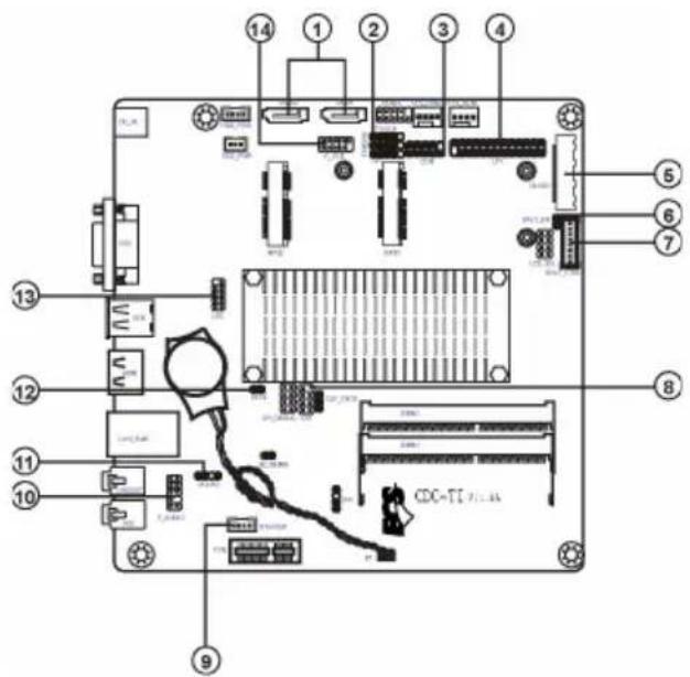
Motherboard Components
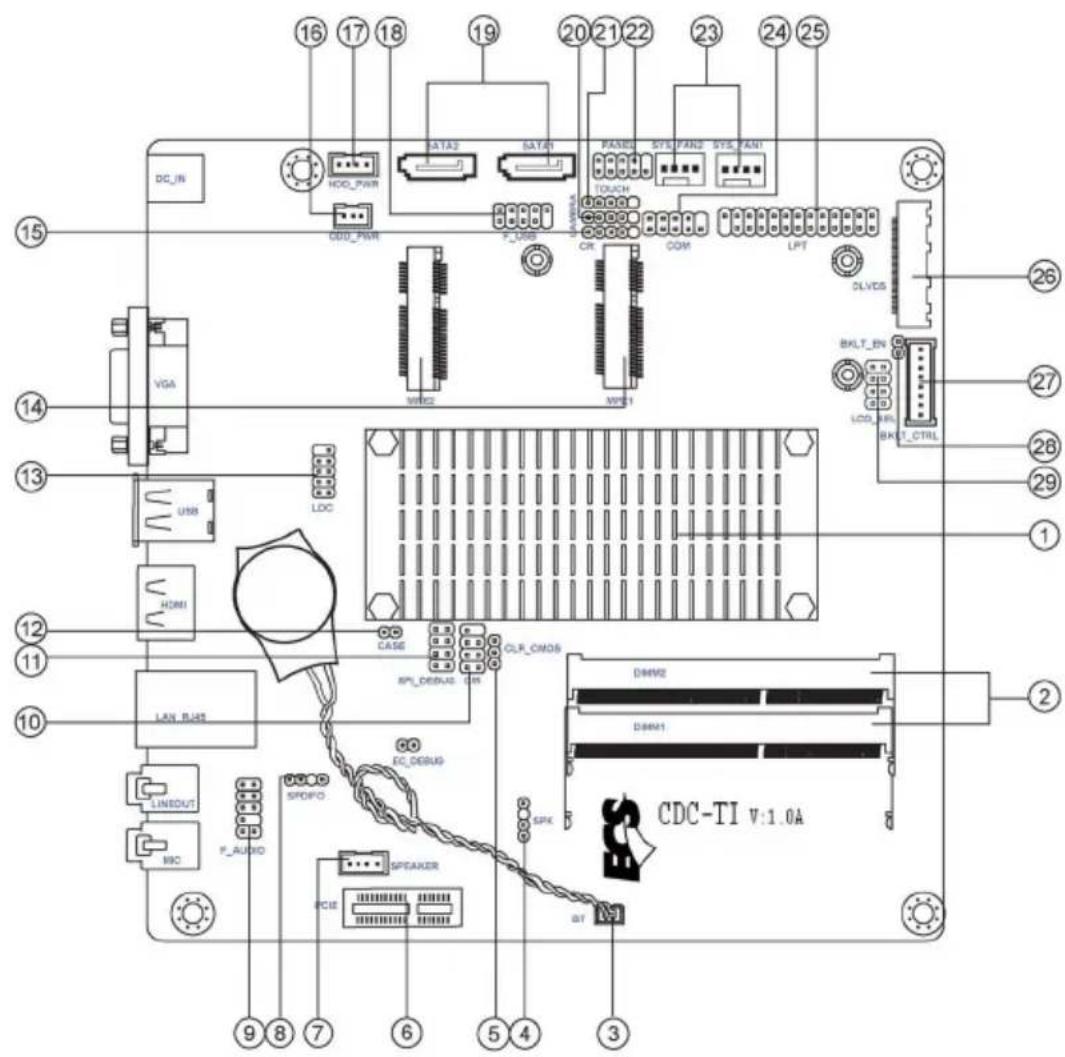

This picture may be different due to Optional Features on specifications.
| LABEL COMPONENTS | |
| 1. CPU Socket LGA559 socket with onboard Cedarview CPU | |
| 2. DIMM_1~2 Two 204-pin DDR3 SDRAM SO-DIMMs | |
| 3. BT Battery connector | |
| 4. SPK Buzzer header (optional) | |
| 5. CLR_CMOS Clear CMOS jumper | |
| 6. PCIE PCI Express x1 slot (optional) | |
| 7. SPEAKER 2 Channels audio speaker header (optional) | |
| 8. SPDIFO SPDIF out header (optional) | |
| 9. F_AUDIO Front panel audio header | |
| 10. CIR Consumer infrared | |
| 11. SPI_DEBUG SPI Debug header-for factory use only | |
| 12. CASE CASE open header | |
| 13. LDC Debug Card Header | |
| 14. MPE1~2 Mini PCI Express x1 slot (one supports half-card, and the other supports full-card) | |
| 15. CR Card reader header | |
| 16. ODD_PWR ODD power connector | |
| 17. HDD_PWR HDD power connector | |
| 18. F_USB Front panel USB 2.0 header | |
| 19. SATA1~2 Serial ATA 3.0 Gb/s connectors | |
| 20. CAMERA CCD header | |
| 21. TOUCH Touch board header | |
| 22. PANEL Front panel switch/LED header | |
| 23. SYS_FAN1~2 4-pin system cooling fan connector | |
| 24. COM Onboard serial port header (optional) | |
| 25. LPT Printer Header (optional) | |
| 26. DLVDS Dual Channels LVDS interface (optional) | |
| 27. BKLT_CTRL LCD panel Backlight control (optional) | |
| 28. BKLT_EN LCD panel Backlight power ON/OFF (optional) | |
| 29. LCD_SEL LCD select jumper (optional) |
I/O Ports
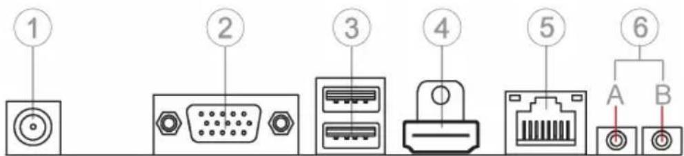
1. DC-IN Port
Connect the DC-IN port to the power adapter.
2. VGA Port
Connect your monitor to the VGA port.
3. USB 2.0 Ports
Use the USB 2.0 ports to connect USB 2.0 devices.
4. HDMI Port
You can connect the display device to the HDMI port.
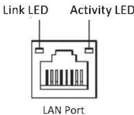
5. LAN Port
Connect an RJ-45 jack to the LAN port to connect your computer to the Network.
| LAN LED Status | Description | |
| Activity LED | OFF | No data |
| Orange blinking | Active | |
| Link LED | OFF | No link |
| Green Link |
6. Audio Ports
Use the two audio jacks to connect audio devices. The left jack is for microphone. The right jack is for stereo line-out signal.
Chapter 2 Installing the Motherboard
2-1. Safety Precautions
Follow these safety precautions when installing the motherboard:
- Wear a grounding strap attached to a grounded device to avoid damage from static electricity.
- Discharge static electricity by touching the metal case of a safely grounded object before working on the motherboard.
- Leave components in the static-proof bags.
• Always remove the AC power by unplugging the power cord from the power outlet before installing or removing the motherboard or other hardware components.
2-2. Installing the motherboard in a Chassis
This motherboard carries a Thin Mini-ITX form factor of 170 x 170 mm. Choose a chassis that accommodates this form factor. Make sure that the I/O template in the chassis matches the I/O ports installed on the rear edge of the motherboard. Most system chassis have mounting brackets installed in the chassis, which corresponds to the holes in the motherboard. Place the motherboard over the mounting brackets and secure the motherboard onto the mounting brackets with screws.
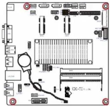

Do not over-tighten the screws as this can stress the motherboard.
2-3. Checking Jumper Settings
This section explains how to set jumpers for correct configuration of the motherboard.

- LCD_SEL: LCD select jumper (optional)


- When your panel connects to LVDS, please check LCD Select header setting first.
- Due to the differences of the panel parameters, please follow the above illustration to place the jumper caps.
2. CLR\_CMOS: Clear CMOS jumper
The following illustration shows the location of the motherboard jumpers. Pin 1 is labeled.


To avoid the system instability after clearing CMOS, we recommend users to enter the main BIOS setting page to "Load Default Settings" and then "Save and Exit Setup".
2-4. Installing Hardware
2-4-1. Installing Memory Modules
- This motherboard accommodates two memory modules. It can support two 204-pin DDR3 SO-DIMM 1066/800.
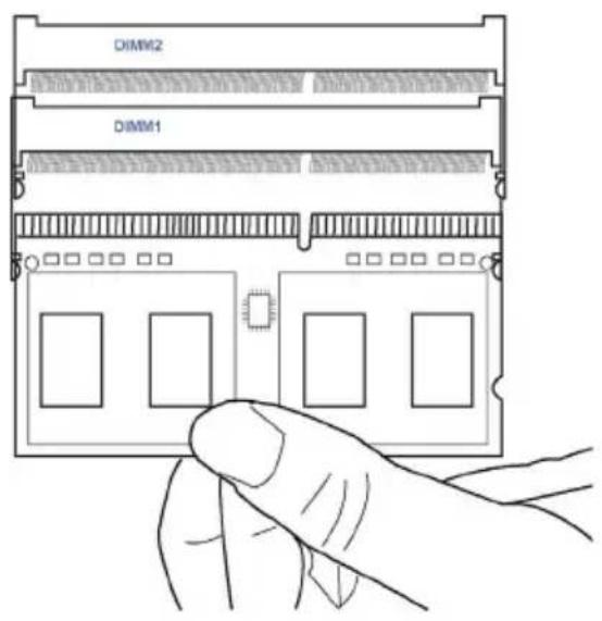
- Do not remove any memory module from its antistatic packaging until you are ready to install it on the motherboard. Handle the modules only by their edges. Do not touch the components or metal parts. Always wear a grounding strap when you handle the modules.
- You must install one module in DIMM1 or two modules in the two slots. Total memory capacity is 4 GB.
- Refer to the following to install the memory modules.
Install the DIMM module into the slot and press it firmly down until it seats correctly. Check that the cutouts on the DIMM module edge connector match the notches in the DIMM slot.
2-4-2. Installing Add-on Cards
The slots on this motherboard are designed to hold expansion cards and connect them to the system bus. Expansion slots are a means of adding or enhancing the motherboard's features and capabilities. With these efficient facilities, you can increase the motherboard's capabilities by adding hardware that performs tasks that are not part of the basic system.

PCIE Slot
The PCI Express x1 slot is fully compliant to the PCI Express Base Specification revision 2.0.
MPE1\~2 Slots
The mini PCI Express x1 slots are for extending usage, one supports half-card, and the other supports full-card.

Before installing an add-on card, check the documentation for the card carefully. If the card is not Plug and Play, you may have to manually configure the card before installation.
Follow these instructions to install an add-on card:
1 Remove a blanking plate from the system case corresponding to the slot you are going to use.
2 Install the edge connector of the add-on card into the expansion slot. Ensure that the edge connector is correctly seated in the slot.
3 Secure the metal bracket of the card to the system case with a screw.

-
For some add-on cards, for example graphics adapters and network adapters, you have to install drivers and software before you can begin using the add-on card.
-
The onboard PCI interface does not support 64-bit SCSI cards.
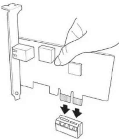
Please refer the following illustrations to install the add-on card:
natural_image
Line drawing of a hand pressing down on a computer RAM module with two buttons and a button labeled '↓' (no text or symbols present)Install the LAN Card in the PCIE X1 slot
Follow these instructions to install a wireless card:
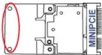
1 Remove a blanking plate from the system case, and insert the wireless card into the MINIPCIE slot rightwards, then tighten the two screws (Please refer to Picture 1).
2 Press the metal connector of the cable into the connector on the wireless card. Ensure that the metal connector is correctly seated (Please refer to Picture 2).
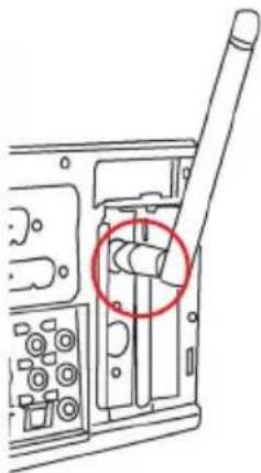
3 Make the other end of the cable (with a gold screw) through the upper hole of the bracket, and tighten the antenna on to the gold screw after installing a metal gasket on the screw (Please refer to Picture 3).
natural_image
Pure electrical circuit lines without any symbolsPicture 1

natural_image
Diagram of a computer monitor case with connectors and a highlighted cable (no text or symbols)Picture 2
natural_image
Technical line drawing of a mechanical component with a red circle highlighting a specific part (no text or symbols present)Picture 3
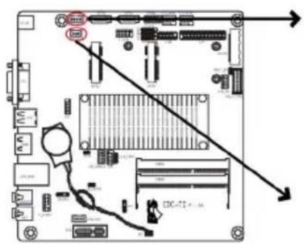
2-4-3. Connecting Optional Devices
Refer to the following for information on connecting the motherboard's optional devices:
| No. Components No. Components | |||
| 1 | S A | T A | |
| 2 TOUCH/CAMERA/CR 9 SPEAKER | |||
| 3 | C | O | M |
| 4 LPT | 11 SPDIFO | ||
| 5 | DLVDS | 12 | CASE |
| 6 | B K | L T | |
| 7 | BKLT_CTRL | 14 | F_USB |
1 \~
0 I E I
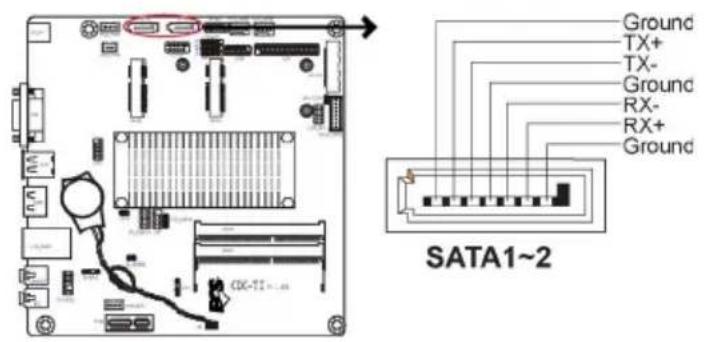
1. SATA1\~2: Serial ATA connectors
SATA1\~2 connectors are used to support the Serial ATA 3.0Gb/s device, simpler disk drive cabling and easier PC assembly. It eliminates limitations of the current Parallel ATA interface. But maintains register compatibility and software compatibility with Parallel ATA.
2. TOUCH/CAMERA/CR: Touch board header/CCD Header/Card reader header
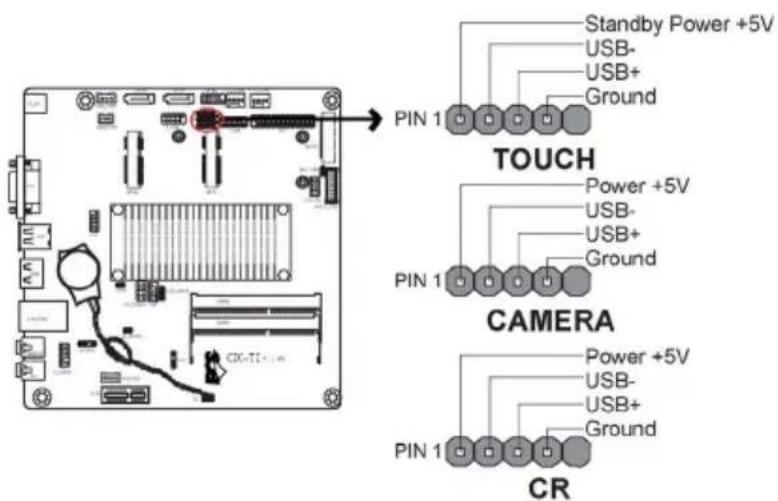

Users please note to install the card to the correct header.
3. COM: Onboard serial port header (optional)
Connect a serial port extension bracket to this header to add a serial port to your system.

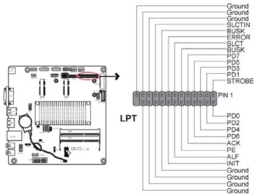
4. LPT: Onboard parallel port Header (optional)
This is a header that can be used to connect to the printer, scanner or other devices.
5. DLVDS: Dual Channels LVDS interface (optional)
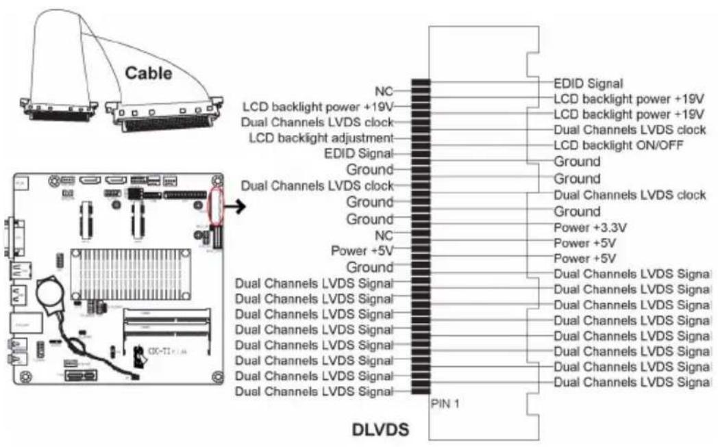

- You can connect the large end of the cable to the LED Panel, and connect the other small end to the slot on the motherboard.
- Due to the chipset limitation, using dual displays LVDS(AIO) + VGA or LVDS(AIO) + HDMI will cause the problem that you may not enter BIOS setup or have the display problem.
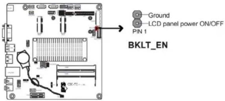
6. BKLT\_EN: LCD panel Backlight power ON/OFF (optional)
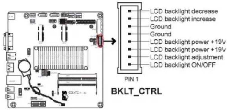
7. BKLT\_CTRL: LCD panel Backlight control (optional)
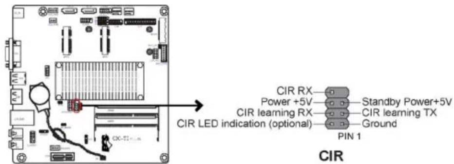
8. CIR: Consumer infrared
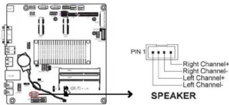
9. SPEAKER: 2 Channels audio speaker header (optional)
10. F\_AUDIO: Front Panel Audio Header
The front panel audio header allows the user to install auxiliary front-oriented microphone and line-out ports for easier access. This header supports HD audio by default. If you want connect an AC' 97 front panel audio to HD onboard headers, please set as below picture.

AC' 97 Audio Configuration: To enable the front panel audio connector to support AC97 Audio mode.
If you use AC' 97 Front Panel, please tick off the option of "Disabled Front Panel Detect". If you use HD Audio Front Panel, please don't tick off "Disabled Front Panel Detect".
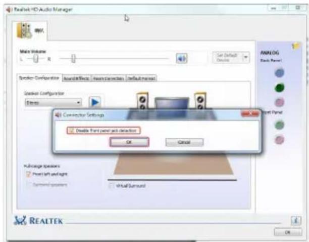
* For reference only
If you use AC' 97 Front Panel, please don't tick off "Using Front Jack Detect". If you use HD Audio Front Panel, please tick off the option of "Using Front Jack Detect".
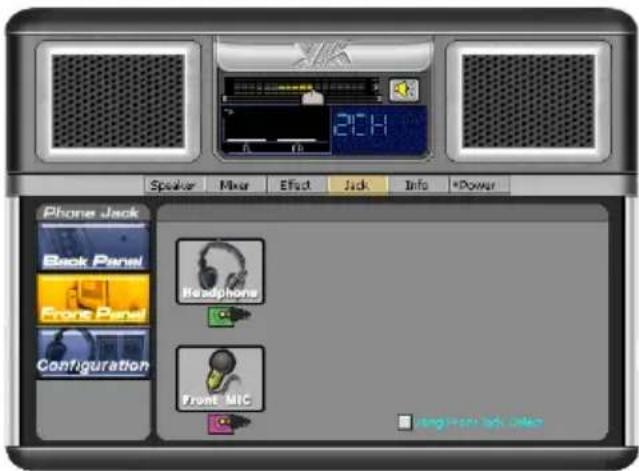
* For reference only
11. SPDIFO: SPDIF out header (optional)
This is an optional header that provides an SPDIFO (Sony/Philips Digital Interface) output to digital multimedia device through optical fiber or coaxial connector.

12. CASE: Chassis Intrusion Detect Header
This detects if the chassis cover has been removed. This function needs a chassis equipped with intrusion detection switch and needs to be enabled in BIOS.


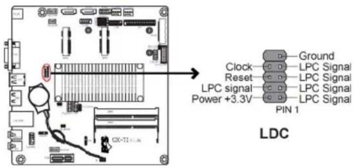
13. LDC: Debug Card Header
14. F\_USB: Front Panel USB 2.0 header
The motherboard has one USB 2.0 headers supporting two USB 2.0 ports. Additionally, some computer cases have USB ports at the front of the case. If you have this kind of case, use auxiliary USB connector to connect the front-mounted ports to the motherboard.
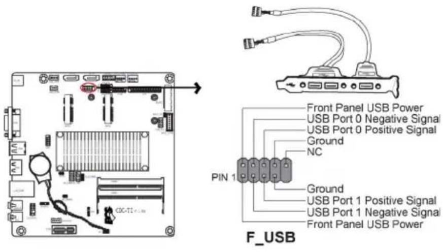

Please make sure that the USB cable has the same pin assignment as indicated above. A different pin assignment may cause damage or system hang-up.
2-4-4. Installing a Hard Disk Drive/Optical Disk Drive/SATA Hard Drive
This section describes how to install a Hard Disk Drive/Optical Disk Drive/SATA Hard Drive.
About SATA Connectors
Your motherboard features two SATA connectors supporting a total of two drives. SATA refers to Serial ATA (Advanced Technology Attachment) is the standard interface for the IDE hard drives which are currently used in most PCs. These connectors are well designed and will only fit in one orientation. Locate the SATA connectors on the motherboard and follow the illustration below to install the SATA hard drives.
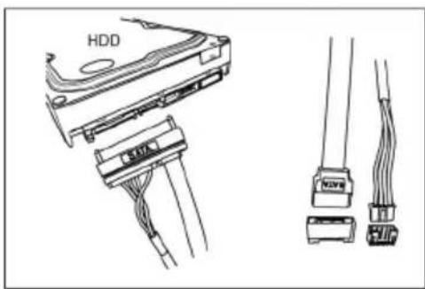
Installing a Hard Disk Drive/Optical Disk Drive/Serial ATA Hard Drives
To install the Hard Disk Drive (HDD)/Optical Disk Drive (ODD)/Serial ATA (SATA) hard drives, use the HDD/ODD/SATA cable that supports the Hard Disk Drive/Optical Disk Drive/Serial ATA protocol. This HDD/ODD/SATA cable comes with a HDD/ODD/SATA power cable. You can connect the comb end of the HDD/ODD/SATA cable to the Hard Disk Drive/Optical Disk Drive and connect the other end to the connectors on the motherboard.
Refer to the illustration below for proper installation:
1 Attach the comb end of the HDD/ODD/SATA cable to the Hard Disk Drive/Optical Disk Drive.
2 Attach the other ends to the connectors on the motherboard.
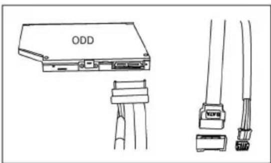
natural_image
Technical line drawing of an ODD device showing cable connections and terminal connectors (no text or symbols)2-4-5. Connecting Case Components
After you have installed the motherboard into a case, you can begin connecting the motherboard components. Refer to the following:

| No. Components No. Components | |||
| 1 HDD_PWR/ODD_PWR 3 SYS_FAN1~2 | |||
| 2 | P | A | N E |
L 4
- HDD_PWR/ODD_PWR: HDD Power connector/ODD Power connector

HDD_PWR

ODD_PWR
2. Panel Header
The front panel header (PANEL) provides a standard set of switch and LED headers commonly found on ATX or Micro ATX cases. Refer to the table below for information:


Hard Drive Activity LED
Connecting pins 1 and 3 to a front panel mounted LED provides visual indication that data is being read from or written to the hard drive. For the LED to function properly, an IDE drive should be connected to the onboard IDE interface. The LED will also show activity for devices connected to the SCSI (hard drive activity LED) connector.
Power/Sleep/Message waiting LED
Connecting pins 2 and 4 to a single or dual-color, front panel mounted LED provides power on/off, sleep, and message waiting indication.
Reset Switch
Supporting the reset function requires connecting pin 5 and 7 to a momentary-contact switch that is normally open. When the switch is closed, the board resets and runs POST.
Power Switch
Supporting the power on/off function requires connecting pins 6 and 8 to a momentary-contact switch that is normally open. The switch should maintain contact for at least 50 ms to signal the power supply to switch on or off. The time requirement is due to internal de-bounce circuitry. After receiving a power on/off signal, at least two seconds elapses before the power supply recognizes another on/off signal.
3. SYS\_FAN1\~2: System Cooling FAN Power Connectors
Connect the system cooling fan connector to SYS_FAN.


Users please note that the fan connector supports the CPU cooling fan of 1.1A \~ 2.2A (26.4W max) at +12V.
4. SPK: Buzzer Header (optional)
Connect the case speaker cable to SPK.

This concludes Chapter 2. The next chapter covers the BIOS.
About the Setup Utility
The computer uses the latest “American Megatrends Inc.” BIOS with support for Windows Plug and Play. The CMOS chip on the motherboard contains the ROM setup instructions for configuring the motherboard BIOS.
The BIOS (Basic Input and Output System) Setup Utility displays the system's configuration status and provides you with options to set system parameters. The parameters are stored in battery-backed-up CMOS RAM that saves this information when the power is turned off. When the system is turned back on, the system is configured with the values you stored in CMOS.
The BIOS Setup Utility enables you to configure:
- Hard drives, diskette drives and peripherals
• Video display type and display options - Password protection from unauthorized use
• Power Management features
The settings made in the Setup Utility affect how the computer performs. Before using the Setup Utility, ensure that you understand the Setup Utility options.
This chapter provides explanations for Setup Utility options.
The Standard Configuration
A standard configuration has already been set in the Setup Utility. However, we recommend that you read this chapter in case you need to make any changes in the future.
This Setup Utility should be used:
- when changing the system configuration
- when a configuration error is detected and you are prompted to make changes to the Setup Utility
- when trying to resolve IRQ conflicts
- when making changes to the Power Management configuration
- when changing the password or making other changes to the Security Setup
Entering the Setup Utility
When you power on the system, BIOS enters the Power-On Self Test (POST) routines. POST is a series of built-in diagnostics performed by the BIOS. After the POST routines are completed, the following message appears:
Press DEL to enter SETUP
Press the delete key to access BIOS Setup Utility.
Resetting the Default CMOS Values
When powering on for the first time, the POST screen may show a “CMOS Settings Wrong” message. This standard message will appear following a clear CMOS data at factory by the manufacturer. You simply need to Load Default Settings to reset the default CMOS values.
Note: Changes to system hardware such as different CPU, memories, etc. may also trigger this message.

Using BIOS
When you start the Setup Utility, the main menu appears. The main menu of the Setup Utility displays a list of the options that are available. A highlight indicates which option is currently selected. Use the cursor arrow keys to move the highlight to other options. When an option is highlighted, execute the option by pressing
Some options lead to pop-up dialog boxes that prompt you to verify that you wish to execute that option. Other options lead to dialog boxes that prompt you for information.
Some options (marked with a icon ▶) lead to submenus that enable you to change the values for the option. Use the cursor arrow keys to scroll through the items in the submenu.
In this manual, default values are enclosed in parenthesis. Submenu items are denoted by a icon.

The default BIOS setting for this motherboard apply for most conditions with optimum performance. We do not suggest users change the default values in the BIOS setup and take no responsibility to any damage caused by changing the BIOS settings.
BIOS Navigation Keys
The BIOS navigation keys are listed below:
| KEY FUNCTION | |
| ESC Exits the current menu | |
| ↑↓→← | Scrolls through the items on a menu |
| +/- | Change Opt. |
| Enter Select | |
| F1 General Help | |
| F2 Previous Value | |
| F3 Optimized Defaults | |
| F4 Save & Exit | |

- For the purpose of better product maintenance, the manufacture reserves the right to change the BIOS items presented in this manual. The BIOS setup screens shown in this chapter are for reference only and may differ from the actual BIOS. Please visit the manufacture's website for updated manual.
- In this Gui BIOS, you can operate by mouse or keyboard. Click: select item; Double click: enter; Right click: exit.
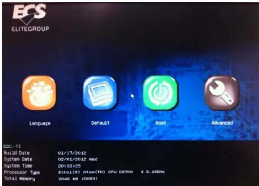
Language
Select the language icon and press
Default
Select the default icon and press
Boot
Select the boot icon and press
Advanced
Select the advanced icon and press
Main Menu
This menu shows the information of BIOS and enables you to set the system language, date and time.

System Language (English)
This item is used to set system language.
Date & Time
The Date and Time items show the current date and time on the computer. If you are running a Windows OS, these items are automatically updated whenever you make changes to the Windows Date and Time Properties utility.
Advanced Menu
The Advanced menu items allow you to change the settings for the CPU and other system.
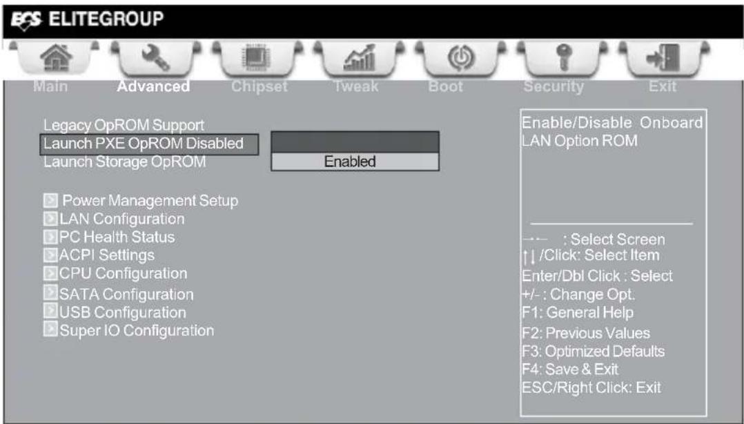

Launch PXE OpROM (Disabled)
The item enables or disables launch PXE Option ROM.
Launch Storage OpROM (Enabled)
Use this item to enable or disable the Storage OpROM.
Power Management Setup
This page sets up some parameters for system power management operation.
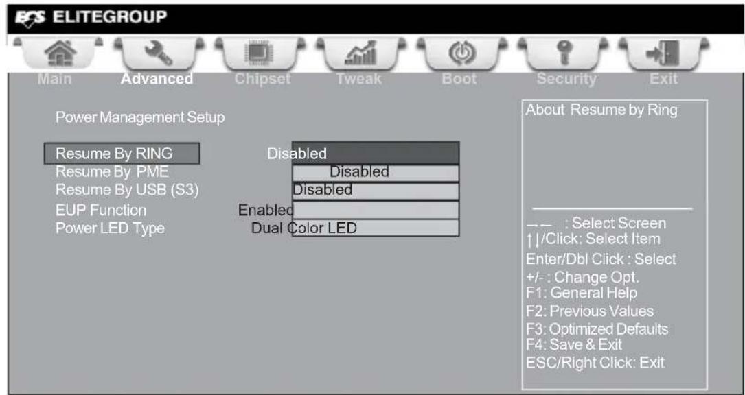
Resume By RING (Disabled)
An input signal on the serial Ring Indicator (RI) line (in other words, an incoming call on the modem) awakens the system from a soft off state.
Resume By PME (Disabled)
The system can be turned off with a software command. If you enable this item, the system can automatically resume if there is an incoming call on the PCI Modem or PCI LAN card. You must use an ATX power supply in order to use this feature. Use this item to do wake-up action if inserting the PCI card.
Resume By USB (S3) (Disabled)
This item allows you to enable/disable the USB device wakeup function from S3 mode.
EUP Function (Enabled)
This item allows user to enable or disable EUP support.
Power LED Type (Dual Color LED)
This item shows the type of the Power LED.
Press
LAN Configuration
The item in the menu shows the LAN-related information that the BIOS automatically detects.

Onboard LAN Controller (Enabled)
Use this item to enable or disable the Onboard LAN.
Press
PC Health Status
On motherboards support hardware monitoring, this item lets you monitor the parameters for critical voltages, temperatures and fan speeds.
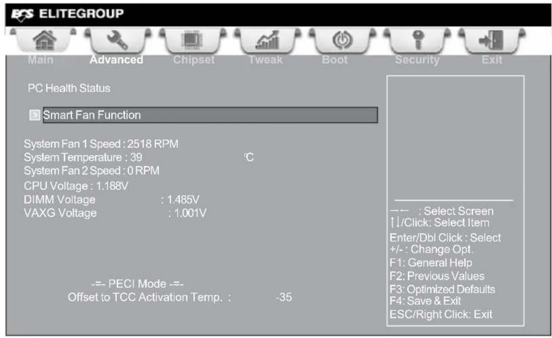
> Smart Fan Function
Scroll to this item and press
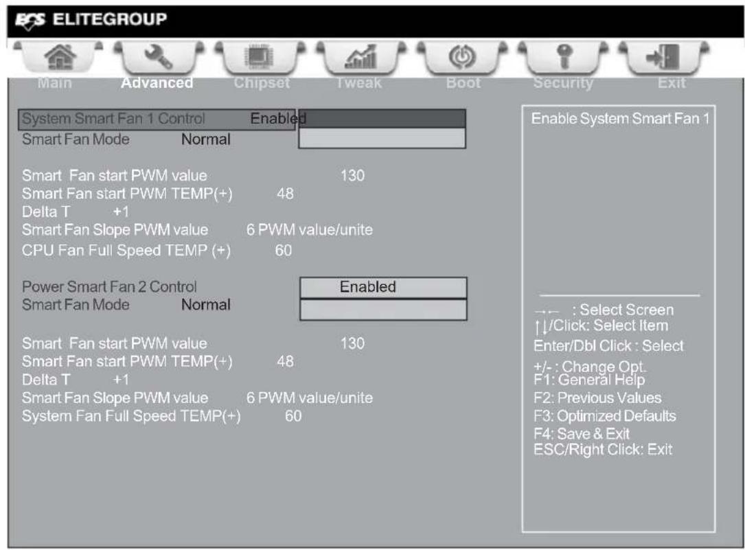
System Smart Fan 1/2 Control (Enabled)
These items enable you to define the System by smartly adjusting the System Fans. When they are set at certain temperature, the System Fan PWM values will change accordingly.
Smart Fan Mode (Normal)
This item allows you to select the fan mode (Normal, Quiet, Silent, or Manual) for a better operation environment. If you choose Normal mode, the fan speed will be auto adjusted depending on the CPU temperature. If you choose Quite mode, the fan speed will be auto minimized for quiet environment. If you choose Silent mode, the fan speed will be auto restricted to make system more quietly. If you choose Manual mode, the fan speed will be adjust depending on users' parameters.
Smart Fan start PWM value (130)
This item is used to set the start PWM value of the smart fan.
Smart Fan start PWM TEMP(+) (48)
This item is used to set the start temperature of the smart fan.
DeltaT (+1)
This item specifies the range that controls CPU temperature and keeps it from going so high or so low when smart fan works.
Smart Fan Slope PWM value (6 PWM value/unite)
This item is used to set the Slope Select PWM of the smart fan.
CPU/System Fan Full Speed TEMP(+) (60)
These items are used to set the CPU/System fan full speed offset values.
Press
System Component Characteristics
These items display the monitoring of the overall inboard hardware health events, such as System temperature, CPU & DIMM voltage, CPU & System fan speed... etc.
- System Fan 1 Speed
- System Temperature
- System Fan 2 Speed
- CPU Voltage
- DIMM Voltage
- VAXG Voltage
Press
ACPI Configuration
The item in the menu shows the highest ACPI sleep state when the system enters suspend.
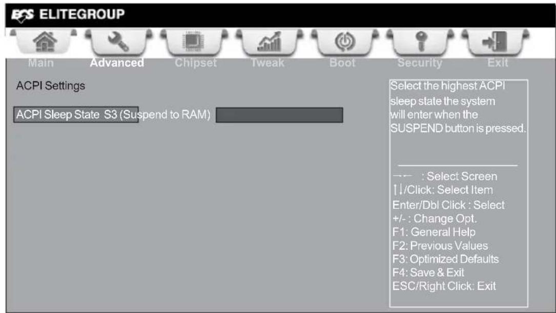
ACPI Sleep State [S3(Suspend to RAM)]
This item allows user to enter the ACPI S3 (Suspend to RAM) Sleep State (default).
Press
CPU Configuration
The item in the menu shows the CPU.
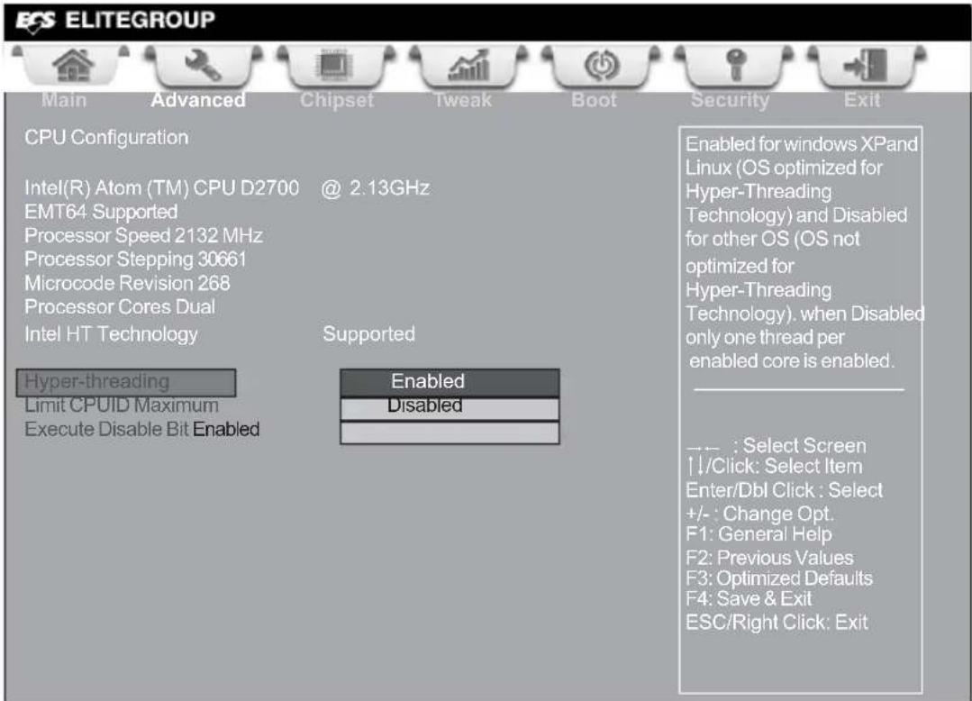
Intel(R) Atom(TM) CPU D2700 @ 2.13GHz
This is display-only field and displays the information of the CPU installed in your computer.
EMT64 (Supported)
This item shows the computer supports EMT64.
Processor Speed (2132MHz)
This item shows the current processor speed.
Processor Stepping (30661)
This item shows the processor stepping version.
Microcode Revision (268)
This item shows the Microcode version.
Processor Cores (Dual)
This item shows the core number of the processor.
Intel HT Technology (Supported)
This item shows the computer supports Intel HT Technology.
Hyper-threading (Enabled)
This item only available when the chipset supports Hyper-threading and you are using a Hyper-threading CPU.
Use this item to enable or disable the maximum CPUID value limit. When supports Prescott and LGA775 CPUs, enables this to prevent the system from "rebooting" when trying to install Windows NT 4.0.
Excute Disable Bit (Enabled)
This item allows the processor to classify areas in memory by where application code can execute and where it cannot. When a malicious worm attempts to insert code in the buffer, the processor disables code execution, preventing damage or worm propagation. Replacing older computers with Execute Disable Bit enabled systems can halt worm attacks, reducing the need for virus related repair.
Press
SATA Configuration
Use this item to show the mode of serial SATA configuration options.
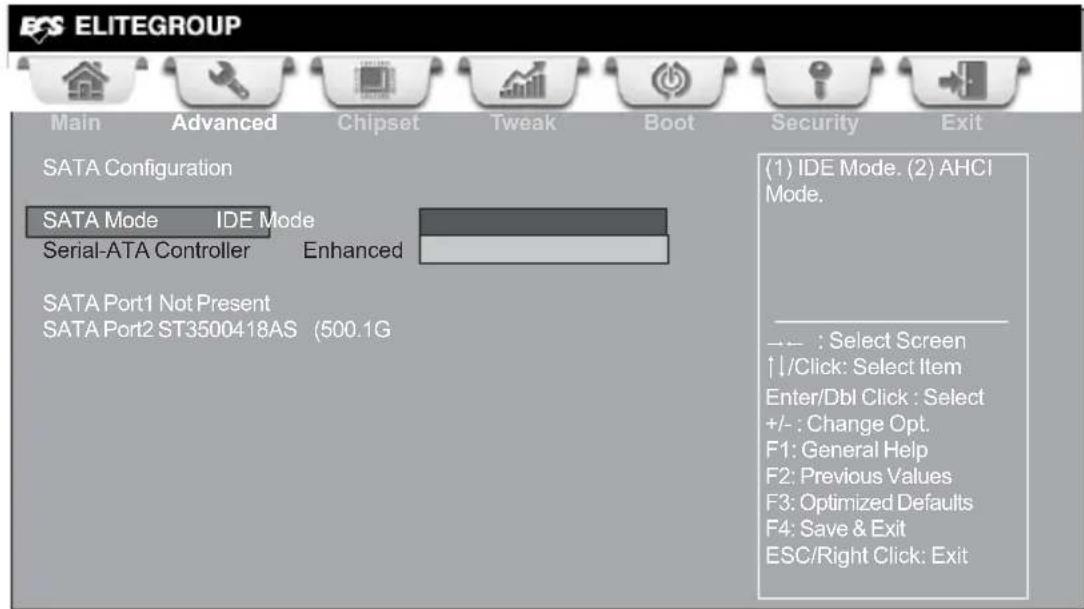
SATA Mode (IDE Mode)
Use this item to select SATA mode.
Serial-ATA Controller (Enhanced)
Use this item to select Serial_ATA controller options: Disabled, Compatible, Enhanced.
SATA Port 1\~2 (Not Present/ST3500418AS (500.1G)
This motherboard supports two SATA channels and each channel allows one SATA device to be installed. Use these items to configure each device on the SATA channel.
Press
USB Configuration
Use this item to show the information of USB configuration.

All USB Devices (Enabled)
Use this item to enable or disable all USB devices.
Legacy USB Support (Enabled)
Use this item to enable or disable support for legacy USB devices.
Press
Super IO Configuration
Use this item to show the information of Super IO configuration.
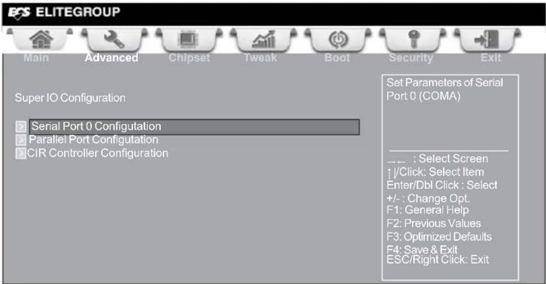
Serial Port 0 Configuration
Scroll to this item and press

Serial Port (Enabled)
This item allows you to enable or disable serial port.
Device Settings (IO=3F8h; IRQ=4)
This item shows the information of the device settings.
Change Settings (Auto)
Use this item to change device settings.
Device Mode (Standard Serial Por...)
This item shows the information of the device mode.
Press
Parallel Port Configuration
Scroll to this item and press
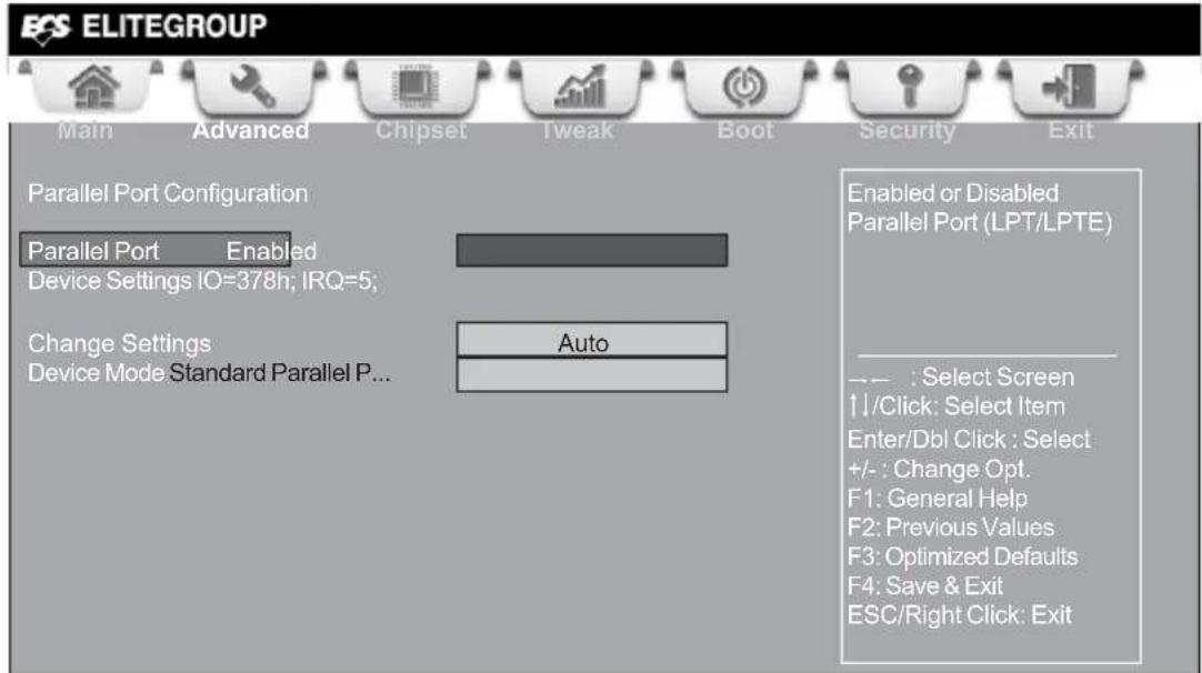
Parallel Port (Enabled)
This item allows you to enable or disable parallel port.
Device Settings (IO=378h; IRQ=5)
This item shows the information of the device settings.
Change Settings (Auto)
Use this item to change device settings.
Device Mode (Standard Serial Por...)
This item shows the information of the device mode.
Press
CIR Controller Configuration
Scroll to this item and press
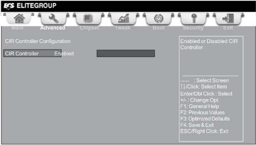
CIR Controller (Enabled)
This item allows you to enable or disable CIR controller.
Press
Chipset Menu
The chipset menu items allow you to change the settings for the North chipset, South chipset and other system.

> North Bridge
Scroll to this item and press
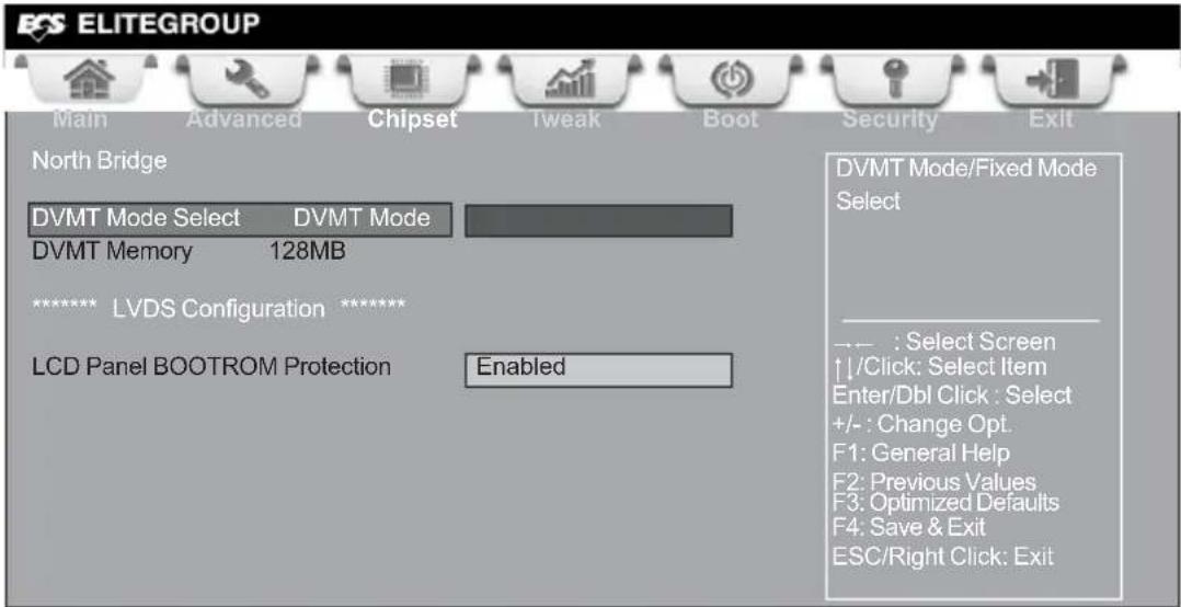
DVMT Mode Select (DVMT Mode)
This item allows you to select the DVMT operating mode.
DVMT Memory (128MB)
When set to Fixed Mode, the graphics driver will reserve a fixed position of the system memory as graphics memory, according to system and graphics requirements.
LCD Panel BOOTROM Protection (Enabled)
This item allows you to enable or disable the LCD Panel BOOTROM protection function.

Due to the chipset limitation, using dual displays LVDS(AIO) + VGA or LVDS(AIO) + HDMI will cause the problem that you may not enter BIOS setup or have the display problem.
Press
South Bridge
Scroll to this item and press
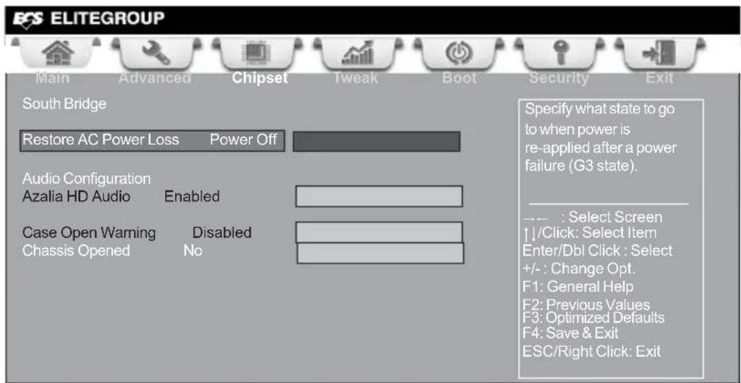
Restore AC Power Loss (Power Off)
This item enables your computer to automatically restart or return to its operating status.
Audio Configuration
This item shows the information of the audio configuration.
Azalia HD Audio (Enabled)
This item enables or disables Azalia HD audio.
Case Open Warning (Disabled)
This item enables or disables the warning if the case is opened up, and the item below indicates the current status of the case.
Chassis Opened (No)
This item indicates whether the case has been opened.
Press
Tweak Menu
This page enables you to monitor or set some information of the processor you have installed in your system.
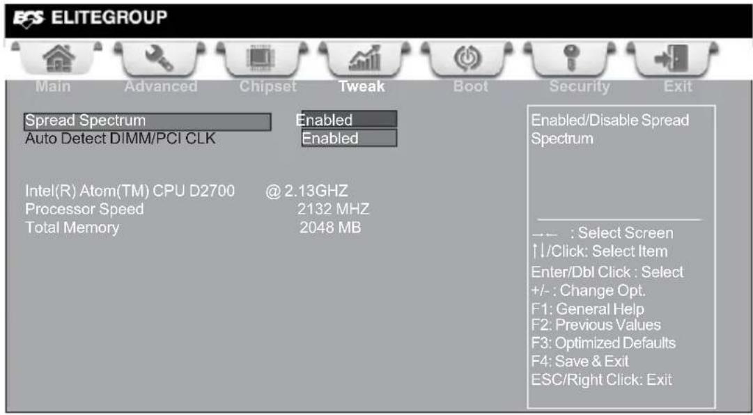
Spread Spectrum (Enabled)
If you enable spread spectrum, it can significantly reduce the EMI (Electro-Magnetic Interference) generated by the system.
Auto Detect DIMM/PCI CLK (Enabled)
When this item is enabled, BIOS will disable the clock signal of free DIMM/PCI slots.
Processor Speed (2132 MHz)
This item shows the current processor speed.
This item shows the total memory.

Warning:
Over-clocking components can adversely affect the reliability of the system and introduce errors into your system. Over-clocking can permanently damage the motherboard by generating excess heat in components that are run beyond the rated limits.
Fail-Safe Procedures for Over-clocking
When end-users encounter failure after attempting over-clocking, please take the following steps to recover from it.
- Shut down the computer.
- Press and hold the "Page Up Key (PgUp)" of the keyboard, and then boot the PC up.
- Two seconds after the PC boots up, release the "Page Up Key (PgUp)".
- The BIOS returns to the default setting by itself.
Boot Menu
This page enables you to set the keyboard NumLock state.
![ECS ELITEGROUP Main Advanced Chipset Tweak Boot Security Exit Boot Configuration Bootup NumLock State On Select the keyboard NumLock state Set Boot Priority 1st Boot Hard Disk: ST350041... 2nd Boot CD/DVD 3rd Boot USB IDE/Floppy 4th Boot USB CD/DVD 5th Boot USB Hard Disk 6th Boot USB Flash 7th Boot Network 8th Boot UEFI Hard Disk Drive Priorities [Press Enter] CD/DVD ROM Drive Priorities [Press Enter] USB/ IDE Floppy Drive Priorities [Press Enter] USB CD/DVD ROM Drive Priorities [Press Enter] USB HardDisk Drive Priorities [Press Enter] USB Flash Drive Priorities [Press Enter] NETWORK Device Priorities [Press Enter] UEFI Boot Drive Priorities [Press Enter]](/content/2026/06/1209687/images/30bfc4300004b22099e05acc893d4e2f284c2f7af4b71973b4dba2e985c8781c.jpg)
Boot Configuration
This item shows the information of the Boot Configuration.
Bootup NumLock State (On)
This item enables you to select NumLock state.
Set Boot Priority
This item enables you to set boot priority for all boot devices.
1st/2nd/3rd/4th/5th/6th/7th/8th Boot
These items show the boot priorities.
Hard Disk / CD/DVD ROM / USB/IDE Floppy / USB CD/DVD ROM / USB HardDisk / USB Flash / NETWORK / UEFI Boot Drive Priorities
These items enable you to specify the sequence of loading the operating system. Press
Security Menu
This page enables you to set setup administrator password and user password.
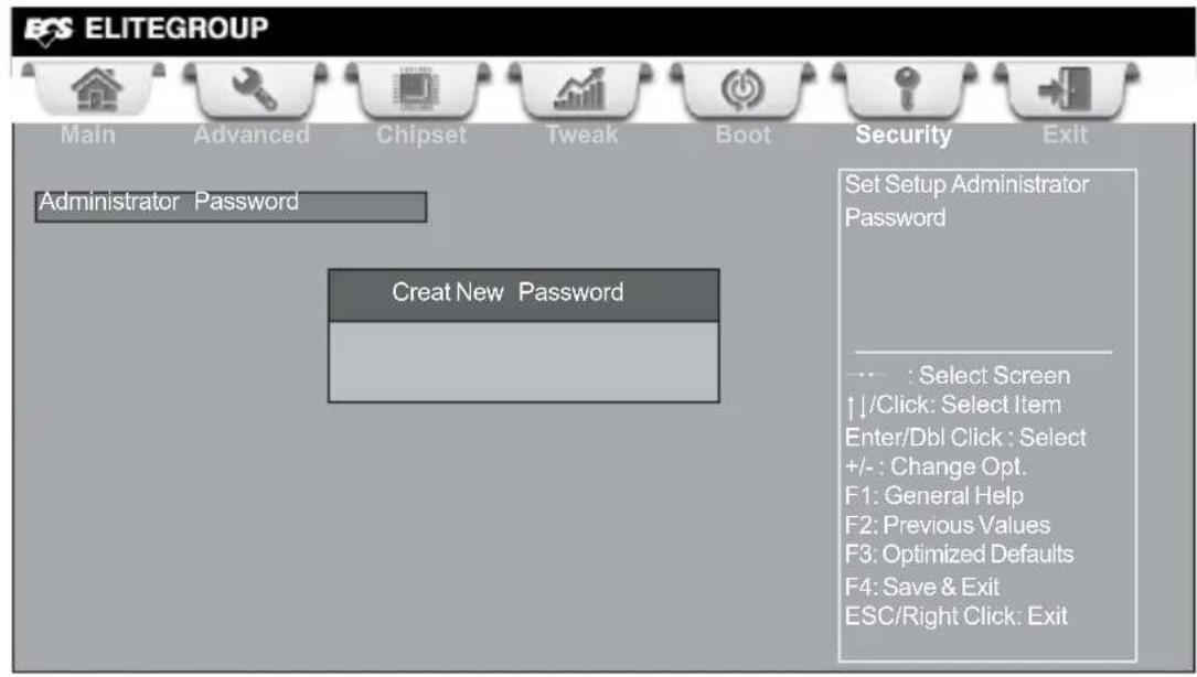
Administrator Password
Press
Exit Menu
This page enables you to exit system setup after saving or without saving the changes.
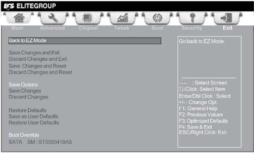
Back to EZ Mode
This item enables you to back to EZ mode.
Save Changes and Exit
This item enables you to exit system setup after saving the changes.
Discard Changes and Exit
This item enables you to exit system setup without saving any changes.
Save Changes and Reset
This item enables you to reset the system setup after saving the changes.
Discard Changes and Reset
This item enables you to reset system setup without saving any changes.
Save Options
This item enables you to save the options that you have made.
Save Changes
This item enables you to save the changes that you have made.
Discard Changes
This item enables you to discard any changes that you have made.
Restore Defaults
This item enables you to restore the system defaults.
Save as User Defaults
This item enables you to save the changes that you have made as user defaults.
This item enables you to restore user defaults to all the setup options.
Boot Override
Use this item to select the boot device.
Updating the BIOS
You can download and install updated BIOS for this motherboard from the manufacturer's Website. New BIOS provides support for new peripherals, improvements in performance, or fixes for known bugs. Install new BIOS as follows:
1 If your motherboard has a BIOS protection jumper, change the setting to allow BIOS flashing.
2 If your motherboard has an item called Firmware Write Protect in Advanced BIOS features, disable it. (Firmware Write Protect prevents BIOS from being overwritten.)
3 Prepare a bootable device or create a bootable system disk. (Refer to Windows online help for information on creating a bootable system disk.)
4 Download the Flash Utility and new BIOS file from the manufacturer's Web site. Copy these files to the bootable device.
5 Turn off your computer and insert the bootable device in your computer. (You might need to run the Setup Utility and change the boot priority items on the Advanced BIOS Features Setup page, to force your computer to boot from the bootable device first.)
6 At the C:\ or A:\ prompt, type the Flash Utility program name and the file name of the new BIOS and then press
7 When the installation is complete, remove the bootable device from the computer and restart your computer. If your motherboard has a Flash BIOS jumper, reset the jumper to protect the newly installed BIOS from being overwritten. The computer will restart automatically.
This concludes Chapter 3. Refer to the next chapter for information on the software supplied with the motherboard.
Chapter 4
Using the Motherboard Software
Auto-installing under Windows XP/Vista/7
The auto-install DVD-ROM makes it easy for you to install the drivers and software. The support software DVD-ROM disc loads automatically under Windows XP/Vista/7. When you insert the DVD-ROM disc in the DVD-ROM drive, the auto-run feature will automatically bring up the installation screen. The screen has four buttons on it: Setup, Utilities, Browse CD and Exit.
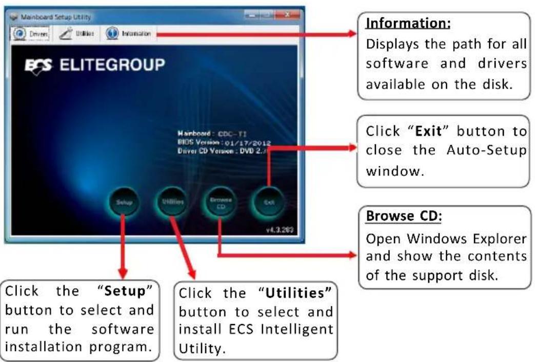
Running Setup
Follow these instructions to install device drivers and software for the motherboard:
- Click Setup. The installation program begins:


The following screens are examples only. The screens and driver lists will be different according to the motherboard you are installing.
The motherboard identification is located in the upper left-hand corner.
- Click Next. The following screen appears:

- Check the box next to the items you want to install. The default options are recommended.
- Click Next to run the Installation Wizard. An item installation screen appears:

- Follow the instructions on the screen to install the items.

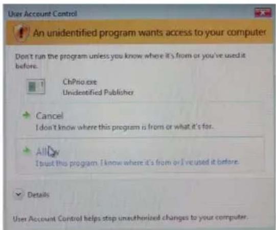
Drivers and software are automatically installed in sequence. Follow the onscreen instructions, confirm commands and allow the computer to re-start a few times to complete the installation.
Windows Vista/7 will appear below UAC (User Account Control) message after the system restart. You must select "Allow" to install the next driver. Continue this process to complete the drivers installation.
Manual Installation
If the auto-install DVD-ROM does not work on your system, you can still install drivers through the file manager for your OS (for example, Windows Explorer). Look for the chipset and motherboard model, and then browse to the directory and path to begin installing the drivers. Most drivers have a setup program (SETUP.EXE) that automatically detects your operating system before installation. Other drivers have the setup program located in the operating system subfolder.
If the driver you want to install does not have a setup program, browse to the operating system subfolder and locate the readme text file (README.TXT or README.DOC) for information on installing the driver or software for your operating system.
ECS Utility Software (Intelligent EZ Utility)
ECS Intelligent EZ Utility provides friendly interfaces under Windows O.S, which makes your computing more easily and conveniently.

These software(s) are subject to change at anytime without prior notice. Please refer to the support disk for available software.
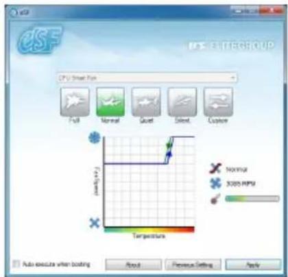
eSF
eSF(Smart Fan) utility provides easy and safe way to adjust fan speed in accordance with your PC's system loading and temperature.
It has five modes to adjust fan speed in a safe range without entering the BIOS to optimize your system cooling environment.
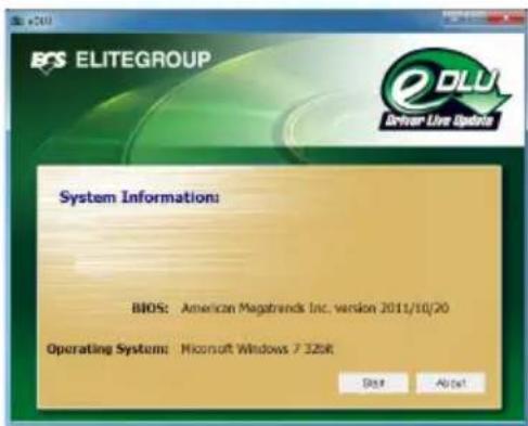
eDLU
ECS eDLU utility makes updating drivers fast and easy. eDLU saves time and hassle by listing all the latest drivers online. Just select the one you prefer and start to download and install the drivers.
CDC-TI USER MANUAL
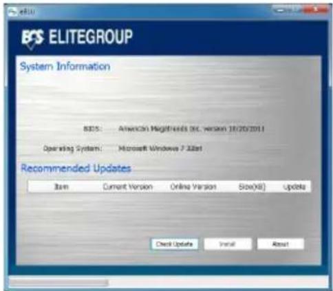
eBLU
ECS eBLU utility makes BIOS update faster and easier. eBLU will list the latest BIOS with a default check-mark. Click"install" button to install.
Chapter 5
Trouble Shooting
Start up problems during assembly
After assembling the PC for the first time you may experience some start up problems. Before calling for technical support or returning for warranty, this chapter may help to address some of the common questions using some basic troubleshooting tips. You may also log onto our ECS website for more information: http://www.ecs.com.tw/ECSWebSite/Support/Support_FAQ.aspx?MenuID=49&childid=M_49&LanID=0
a) System does not power up and the fans are not running.
- Disassemble the PC to remove the VGA adaptor card, DDR memory, LAN, USB and other peripherals including keyboard and mouse. Leave only the motherboard, CPU with CPU cooler and power supply connected. Make sure the power cord is plugged into the wall socket & the switch on the Power Supply Unit (PSU) is turned "on" as well. Turn on again to see if the CPU and power supply fans are running.
- Make sure to remove any unused screws or other metal objects such as screwdrivers from the inside PC case. This is to prevent damage from short circuit.
- Check the CPU FAN connector is connected to the motherboard.
- For Intel platforms check the pins on the CPU socket for damage or bent. A bent pin may cause failure to boot and sometimes permanent damage from short circuit.
- Check the 12V power connector is connected to the motherboard.
- Check that the 12V power & ATX connectors are fully inserted into the motherboard connectors. Make sure the latches of the cable and connector are locked into place.
b) Power is on, fans are running but there is no display
- Make sure the monitor is turned on and the monitor cable is properly connected to the PC.
- Check the VGA adapter card (if applicable) is inserted properly.
- Listen for beep sounds. If you are using internal PC speaker make sure it is connected.
a. continuous 3 short beeps: memory not detected
b. 1 long beep and 8 short beeps: VGA not detected
c) The PC suddenly shuts down while booting up.
-
The CPU may experience overheating so it will shutdown to protect itself. Apply the thermal grease onto the CPU heatsink & ensure the CPU fan is well-connected with the CPU heatsink. Check if the CPU fan is working properly while the system is running.
-
From the BIOS setting, try to disable the Smartfan function to let the fan run at default speed. Doing a Load Optimised Default will also disable the Smartfan.
Start up problems after prolong use
After a prolong period of use your PC may experience start up problems again. This may be caused by breakdown of devices connected to the motherboard such as HDD, CPU fan, etc. The following tips may help to revive the PC or identify the cause of failure.
- Clear the CMOS values using the CLR_CMOS jumper. Refer to CLR_CMOS jumper in Chapter 2 for Checking Jumper Settings in this user manual. When completed, follow up with a Load Optimised Default in the BIOS setup.
- Check the CPU cooler fan for dust. Long term accumulation of dust will reduce its effectiveness to cool the processor. Clean the cooler or replace a new one if necessary.
- Check that the 12V power & ATX connectors are fully inserted into the motherboard connectors. Make sure the latches of the cable and connector are locked into place.
- Remove the hard drive, optical drive or DDR memory to determine which of these components may be at fault.
- Check whether there is any bulked up electrolytic capacitor or abnormal component.
Please logo onto our ECS website: http://www.ecs.com.tw/ECSWebSite/Support/Technical_Support_List.aspx?MenuID=50&LanID=0 for more information.
Maintenance and care tips
Your computer, like any electrical appliance, requires proper care and maintenance. Here are some basic PC care tips to help prolong the life of the motherboard and keep it running as best as it can.
- Keep your computer in a well ventilated area. Leave some space between the PC and the wall for sufficient airflow.
- Keep your computer in a cool dry place. Avoid dusty areas, direct sunlight and areas of high moisture content.
- Routinely clean the CPU cooler fan to remove dust and hair.
- In places of hot and humid weather you should turn on your computer once every other week to circulate the air and prevent damage from humidity.
- Add more memory to your computer if possible. This not only speeds up the system but also reduces the loading of your hard drive to prolong its life span.
- If possible, ensure the power cord has an earth ground pin directly from the wall outlet. This will reduce voltage fluctuation that may damage sensitive devices.
Basic Troubleshooting Flowchart
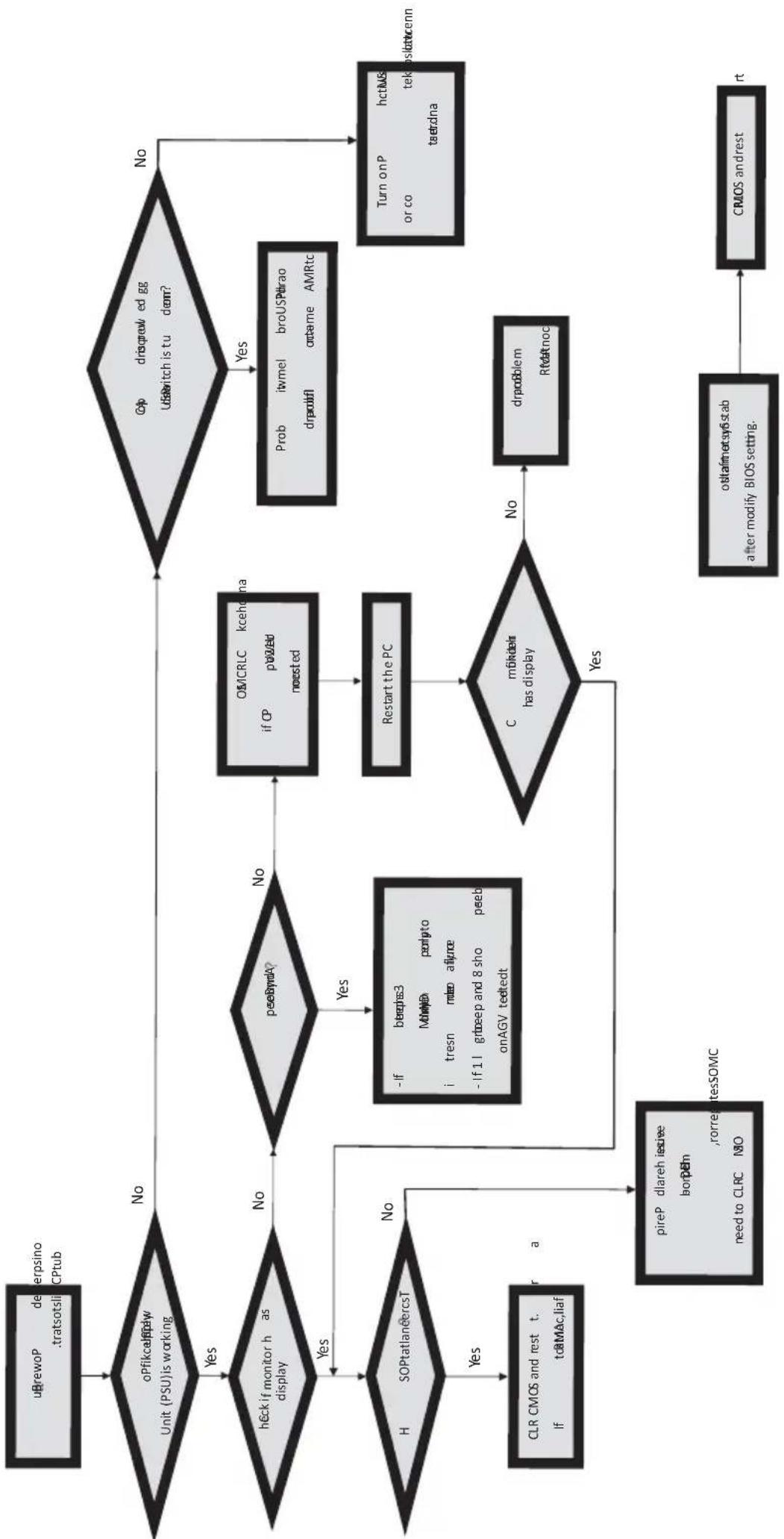
flowchart
graph TD
    A["uBrewoP deperpsino .tratsotsli CPtub"] --> B{oPfikcalplay Unit (PSU) is working}
    B -->|Yes| C{heck if monitor h as display}
    C -->|No| D{peebrydA?}
    D -->|Yes| E["H SOPtatlanercsT"]
    D -->|No| F["OMCRLC kcehdna if CP p#ed noested"]
    F --> G["Restart the PC"]
    G --> H{C moidals has display}
    H -->|Yes| I["pireP dlareh isee borpem ,rorregtesSOMC need to CLRC NO"]
    H -->|No| J["drpooblem R#atnoc"]
    J --> K["CRIOS andrest start"]
    C -->|Yes| L["Check if monitor h as display"]
    L --> M{peebrydA?}
    M -->|No| N["OmCRLC kcehdna if CP p#ed noested"]
    N --> O["Restart the PC"]
    O --> H
    M -->|Yes| P["Prob itvmel broUSPhrao drpodif orame AMRtc"]
    P --> Q["Turn onP hctUS or co tekoslatuenn taetzna"]
    Q --> K
Memo
Chapter 5


- Disclaimer
- Trademark Recognition
- Federal Communications Commission (FCC)
- Declaration of Conformity
- Canadian Department of Communications
- Preface i
- Chapter 1 1
- Introducing the Motherboard 1
- Chapter 2 7
- Installing the Motherboard 7
- Chapter 3 27
- Using BIOS 27
- Chapter 4 53
- Using the Motherboard Software 53
- Chapter 5 57
- Trouble Shooting 57
- Introduction
- Package Contents
- Specifications
- Motherboard Components
- I/O Ports
- DC-IN Port
- VGA Port
- USB 2.0 Ports
- HDMI Port
- LAN Port
- Audio Ports
- Chapter 2 Installing the Motherboard
- 2-1. Safety Precautions
- 2-2. Installing the motherboard in a Chassis
- 2-3. Checking Jumper Settings
- CLR\_CMOS: Clear CMOS jumper
- 2-4. Installing Hardware
- 2-4-1. Installing Memory Modules
- 2-4-2. Installing Add-on Cards
- PCIE Slot
- MPE1\~2 Slots
- 2-4-3. Connecting Optional Devices
- SATA1\~2: Serial ATA connectors
- TOUCH/CAMERA/CR: Touch board header/CCD Header/Card reader header
- COM: Onboard serial port header (optional)
- LPT: Onboard parallel port Header (optional)
- DLVDS: Dual Channels LVDS interface (optional)
- BKLT\_EN: LCD panel Backlight power ON/OFF (optional)
- BKLT\_CTRL: LCD panel Backlight control (optional)
- CIR: Consumer infrared
- SPEAKER: 2 Channels audio speaker header (optional)
- F\_AUDIO: Front Panel Audio Header
- SPDIFO: SPDIF out header (optional)
- CASE: Chassis Intrusion Detect Header
- LDC: Debug Card Header
- F\_USB: Front Panel USB 2.0 header
- 2-4-4. Installing a Hard Disk Drive/Optical Disk Drive/SATA Hard Drive
- About SATA Connectors
- Installing a Hard Disk Drive/Optical Disk Drive/Serial ATA Hard Drives
- 2-4-5. Connecting Case Components
- Panel Header
- Hard Drive Activity LED
- Power/Sleep/Message waiting LED
- Reset Switch
- Power Switch
- SYS\_FAN1\~2: System Cooling FAN Power Connectors
- SPK: Buzzer Header (optional)
- About the Setup Utility
- The Standard Configuration
- Entering the Setup Utility
- Resetting the Default CMOS Values
- Using BIOS
- BIOS Navigation Keys
- Language
- Default
- Boot
- Advanced
- Main Menu
- System Language (English)
- Date & Time
- Advanced Menu
- Launch PXE OpROM (Disabled)
- Launch Storage OpROM (Enabled)
- Power Management Setup
- Resume By RING (Disabled)
- Resume By PME (Disabled)
- Resume By USB (S3) (Disabled)
- EUP Function (Enabled)
- Power LED Type (Dual Color LED)
- LAN Configuration
- Onboard LAN Controller (Enabled)
- PC Health Status
- > Smart Fan Function
- System Smart Fan 1/2 Control (Enabled)
- Smart Fan Mode (Normal)
- Smart Fan start PWM value (130)
- Smart Fan start PWM TEMP(+) (48)
- DeltaT (+1)
- Smart Fan Slope PWM value (6 PWM value/unite)
- CPU/System Fan Full Speed TEMP(+) (60)
- System Component Characteristics
- ACPI Configuration
- ACPI Sleep State [S3(Suspend to RAM)]
- CPU Configuration
- EMT64 (Supported)
- Processor Speed (2132MHz)
- Processor Stepping (30661)
- Microcode Revision (268)
- Processor Cores (Dual)
- Intel HT Technology (Supported)
- Hyper-threading (Enabled)
- Excute Disable Bit (Enabled)
- SATA Configuration
- SATA Mode (IDE Mode)
- Serial-ATA Controller (Enhanced)
- SATA Port 1\~2 (Not Present/ST3500418AS (500.1G)
- USB Configuration
- All USB Devices (Enabled)
- Legacy USB Support (Enabled)
- Super IO Configuration
- Serial Port 0 Configuration
- Serial Port (Enabled)
- Device Settings (IO=3F8h; IRQ=4)
- Change Settings (Auto)
- Device Mode (Standard Serial Por...)
- Parallel Port Configuration
- Parallel Port (Enabled)
- CIR Controller Configuration
- CIR Controller (Enabled)
- Chipset Menu
- > North Bridge
- DVMT Mode Select (DVMT Mode)
- DVMT Memory (128MB)
- LCD Panel BOOTROM Protection (Enabled)
- South Bridge
- Restore AC Power Loss (Power Off)
- Audio Configuration
- Azalia HD Audio (Enabled)
- Case Open Warning (Disabled)
- Chassis Opened (No)
- Tweak Menu
- Spread Spectrum (Enabled)
- Auto Detect DIMM/PCI CLK (Enabled)
- Processor Speed (2132 MHz)
- Fail-Safe Procedures for Over-clocking
- Boot Menu
- Boot Configuration
- Bootup NumLock State (On)
- Set Boot Priority
- 1st/2nd/3rd/4th/5th/6th/7th/8th Boot
- Security Menu
- Administrator Password
- Exit Menu
- Back to EZ Mode
- Save Changes and Exit
- Discard Changes and Exit
- Save Changes and Reset
- Discard Changes and Reset
- Save Options
- Save Changes
- Discard Changes
- Restore Defaults
- Save as User Defaults
- Boot Override
- Updating the BIOS
- Chapter 4
- Using the Motherboard Software
- Auto-installing under Windows XP/Vista/7
- Running Setup
- Manual Installation
- ECS Utility Software (Intelligent EZ Utility)
- eSF
- eDLU
- eBLU
- Chapter 5
- Trouble Shooting
- Start up problems during assembly
- a) System does not power up and the fans are not running.
- b) Power is on, fans are running but there is no display
- c) The PC suddenly shuts down while booting up.
- Start up problems after prolong use
- Maintenance and care tips
Brand : ECS
Model : CDC-TI
Category : Tablet