
APLD-I2 - Tablet ECS - Free user manual and instructions
Find the device manual for free APLD-I2 ECS in PDF.

| Product Type | Tablet (mainboard Intel Apollo Lake) |
| Processor | Intel Apollo Lake SoC (onboard) |
| Memory | Up to 8GB DDR3L 1866 MHz (2 x SO-DIMM slots) |
| Storage | M.2 SATA SSD (Key B 2242/2280) and 2 x SATA 6Gb/s |
| Display Outputs | HDMI, VGA (or DP), supports multiple monitors |
| Networking | Gigabit Ethernet (Realtek RTL8111H), M.2 slot for WiFi/BT |
| Audio | Realtek ALC662-VD0-GR 6-channel HD Audio, line-in/out/mic |
| USB Ports | 2 x USB 3.0 (rear), 2 x USB 2.0 (rear), plus internal headers for 6 more |
| Expansion Slots | 2 x M.2 (Key A+E for WiFi/BT, Key B for SSD) |
| Power Supply | DC_IN port (external adapter) or ATX_POWER header (optional) |
| Form Factor | Mini ITX (170mm x 170mm) |
| BIOS | AMI BIOS with 128Mb SPI Flash, supports PnP, ACPI, S3/S4 |
| Compliance | FCC Part 15 Class B, CE, EN 55032/55024/60950 |
| Operating System | Compatible with Windows, Linux (not pre-installed) |
Frequently Asked Questions - APLD-I2 ECS
User questions about APLD-I2 ECS
0 question about this device. Answer the ones you know or ask your own.
Ask a new question about this device
Download the instructions for your Tablet in PDF format for free! Find your manual APLD-I2 - ECS and take your electronic device back in hand. On this page are published all the documents necessary for the use of your device. APLD-I2 by ECS.
USER MANUAL APLD-I2 ECS
The information in this document is subject to change without notice. The manufacturer makes no representations or warranties with respect to the contents hereof and specifically disclaims any implied warranties of merchantability or fitness for any particular purpose. The manufacturer reserves the right to revise this publication and to make changes from time to time in the content hereof without obligation of the manufacturer to notify any person of such revision or changes.
Federal Communications Commission (FCC)
This equipment has been tested and found to comply with the limits for a Class B digital device, pursuant to Part 15 of the FCC Rules. These limits are designed to provide reasonable protection against harmful interference in a residential installation. This equipment generates, uses, and can radiate radio frequency energy and, if not installed and used in accordance with the instructions, may cause harmful interference to radio communications. However, there is no guarantee that interference will not occur in a particular installation. If this equipment does cause harmful interference to radio or television reception, which can be determined by turning the equipment off and on, the user is encouraged to try to correct the interference by one or more of the following measures:
•Reorient or relocate the receiving antenna
- Increase the separation between the equipment and the receiver
- Connect the equipment onto an outlet on a circuit different from that to which the receiver is connected
- Consult the dealer or an experienced radio/TV technician for help
Shielded interconnect cables and a shielded AC power cable must be employed with this equipment to ensure compliance with the pertinent RF emission limits governing this device. Changes or modifications not expressly approved by the system's manufacturer could void the user's authority to operate the equipment.
Declaration of Conformity
This device complies with part 15 of the FCC rules. Operation is subject to the following conditions:
•This device may not cause harmful interference.
- This device must accept any interference received, including interference that may cause undesired operation.
This device is in conformity with the following EC/EMC directives:
☐ EN 55032 Electromagnetic compatibility of multimedia equipment - Emission requirements
☐ EN 61000-3-2 Electromagnetic Compatibility(EMC) Part 3-2: Limits-Limits for harmonic current emissions (equipment input current ≤16A per phase)
☐ EN 61000-3-3 Electromagnetic Compatibility(EMC) Part 3-3: Limits-Limitation of voltage changes, voltage fluctuations and flicker in public low-voltage supply systems, for equipment with rated current ≤16A per phase and not subject to conditional connection
☐ EN 55024 Information technology equipment-Immunity characteristics-Limits and methods of measurement
☐ EN 60950 Safety for information technology equipment including electrical business equipment
□ CE marking

Preface i
Brief Introduction 1
Specifications....1
Motherboard Components....3
Header Pin Definition and Jumper Settings....5
I/O Ports....8
Multi-language Quick Installation Guide 9
English....9
Simplified Chinese....11
Korean....13
Indonesian....15
Japanese....17
Vietnamese....19
Brief Introduction
Specifications
| SoC | Onboard Intel ^ Apollo Lake 1170 BGANote: Please go to our website for the latest CPU support list. |
| Memory | 2 channel DDR3L SO-DIMM memory architecture2 x 204-pin DDR3L SO-DIMM socket supports up to 8 GBSupports DDR3L 1866 MHz SDRAMNote: Please go to our website for the latest Memory support list. |
| Expansion Slots | 2 x M.2 slot (key A+E 2230 for WIFI/BT, key B 2242/2280 for SATA SSD) |
| Storage | Supported by Intel ^ Apollo Lake 1170 BGA- 2 x Serial ATA 6Gb/s devices |
| Audio | Realtek ALC662-VD0-GR 6CH HD Audio CODEC- 6 Channel High Definition Audio Codec- Compliant with HD audio specification |
| LAN • Realtek RTL8111H Gigabit LAN | |
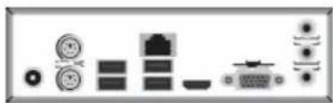
| Rear Panel I/O | 1 x DC_IN port1 x PS/2 Keyboard & PS/2 Mouse connectors1 x D-sub (VGA) port*(or DP port)1 x HDMI port2 x USB 3.0 ports1 x RJ45 LAN connector2 x USB 2.0 ports1 x Audio port (1 x line-in, 1 x line-out, 1 x Microphone) |
| Internal I/OConnectors & Headers | 1 x 4-pin SYS_FAN connector2 x USB 2.0 headers support additional four USB 2.0 ports1 x USB 3.0 header supports additional two USB 3.0 ports2 x Serial ATA 6Gb/s connectors1 x Buzzer1 x Front Panel switch/LED header1 x Front Panel audio header1 x Clear CMOS jumper1 x MONO jumper2 x COM headers1 x Case open header1 x SATA power connector1 x Debug card header1 x Printer header1 x Amplifier Speaker header |
System BIOS
• AMI BIOS with 128Mb SPI Flash ROM
- Supports Plug and Play
- Supports ACPI & DMI
- Supports STR (S3) /STD (S4)
- Supports Hardware monitor
- Audio, LAN, can be disabled in BIOS
- F7 hot key for boot up devices option
- Support PgUp clear CMOS Hotkey (PS2 KB Model only)
- Add BIOS parameters and copy to USB Flash Drive
Form Factor
- Mini ITX Size, 170mm x 170mm
QR Code for the complete manual download on ECS website: http://www.ecs.com.tw

Motherboard Components


Table of Motherboard Components
| LABEL COMPONENTS | |
| 1. SoC Intel® Apollo Lake 1170 BGA | |
| 2. DIMM1~2 204-pin DDR3L | SDRAM SO-DIMM |
| 3. F_PANEL Front panel switch/LED header | |
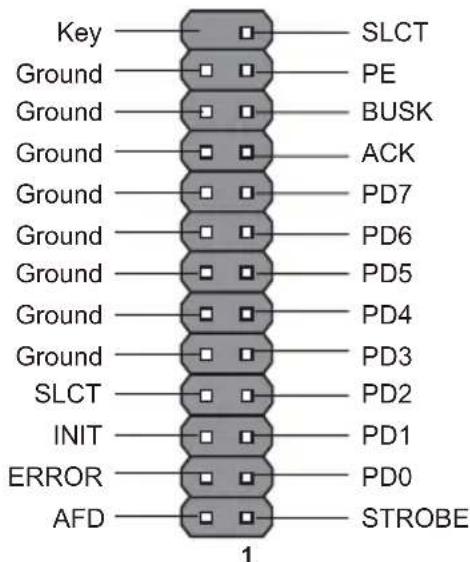
| 4. LPT Onboard parallel port header | |
| 5. CLR_CMOS Clear CMOS jumper | |
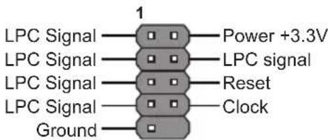
| 6. LDC Debug card header | |
| 7. CASE Case open header | |
| 8. COM1~2 Onboard serial port headers | |
| 9. TXE_UNLOCK TXE Unlock jumper | |
| 10. SYS_FAN 4-pin system cooling fan connector | |
| 11. SATA_PWR SATA power connector | |
| 12. SATA1~2 Serial ATA 6Gb/s connectors | |
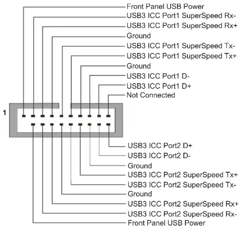
| 13. USB3F Front panel USB 3.0 header | |
| 14. SPKR | Amplifier speaker header |
| 15. MONO | MONO jumper |
| 16. F_AUDIO | Front panel audio header |
| 17. M2_2280M/M2_2230 | M.2 slots |
| 18. F_USB1~2 | Front panel USB 2.0 headers |
| 19. BT Battery | |
| 20. BZ Buzzer | |
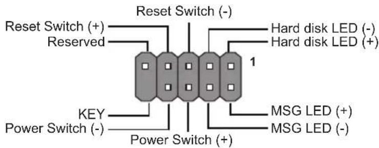
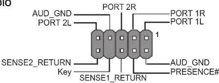
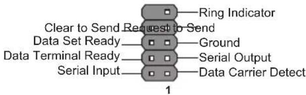
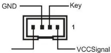
Header Pin Definition and Jumper Settings
F_PANEL
F_AUDIO
COM1\~2
F_USB1\~2

SPKR
SYS_FAN

CASE


LDC
LPT
USB3F
flowchart
graph TD
    A["1"] --> B["Front Panel USB Power"]
    A --> C["USB3 ICC Port1 SuperSpeed Rx-"]
    A --> D["USB3 ICC Port1 SuperSpeed Rx+"]
    A --> E["Ground"]
    A --> F["USB3 ICC Port1 SuperSpeed Tx-"]
    A --> G["USB3 ICC Port1 SuperSpeed Tx+"]
    A --> H["Ground"]
    A --> I["USB3 ICC Port1 D-"]
    A --> J["USB3 ICC Port1 D+"]
    A --> K["Not Connected"]
    A --> L["USB3 ICC Port2 D+"]
    A --> M["USB3 ICC Port2 D-"]
    A --> N["Ground"]
    A --> O["USB3 ICC Port2 SuperSpeed Tx+"]
    A --> P["USB3 ICC Port2 SuperSpeed Tx-"]
    A --> Q["Ground"]
    A --> R["USB3 ICC Port2 SuperSpeed Rx+"]
    A --> S["USB3 ICC Port2 SuperSpeed Rx-"]
    A --> T["Front Panel USB Power"]
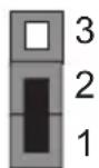
MONO Jumper
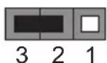
1-2: Stereo
2-3: Mono
MONO
CLR_CMOS Jumper
1-2: NORMAL
2-3: CLEAR CMOS
Before clearing the CMOS, make sure to turn off the system.
CLR_CMOS
TXE_UNLOCK Jumper
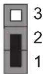
1-2: NORMAL
2-3: Override
TXE_UNLOCK
I/O Ports
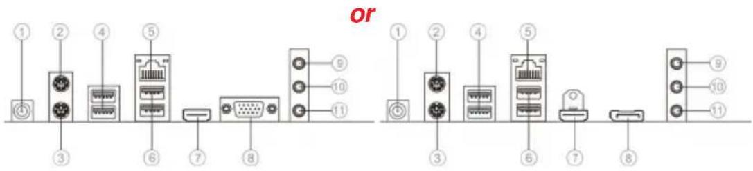
1. DC\_IN Port\* (optional)
Connect the DC_IN port to the power adapter.
2. PS/2 Mouse (green)
Use the upper PS/2 port to connect a PS/2 mouse.
3. PS/2 Keyboard (purple)
Use the lower PS/2 port to connect a PS/2 keyboard.
4. USB 3.0 Ports
Use the USB 3.0 port to connect USB 3.0 device.
5. LAN Port
Connect an RJ-45 jack to the LAN port to connect your computer to the Network.
| LAN LED Status | us Descri | p tion |
| Activity LED | OFF No data | |
| Orange blinking | Active | |
| Link LED | OFF No link | |
| Green Link | (10/100 port) | |
| Orange | L (Gig a port) |

6. USB 2.0 Ports
Use the USB 2.0 ports to connect USB 2.0 devices.
7. HDMI Port
You can connect the display device to the HDMI port.
8. VGA Port\* (or DP Port\*) (optional)
You can connect the monitor to the VGA port (you can connect the display device to the display port).
9. Line-in (blue)
It can be connected to an external CD/DVD player, Tape player or other audio devices for audio input.
10. Line-out (green)
It is used to connect to speakers or headphones.
11. Microphone (pink)
It is used to connect to a microphone.

Note: * VGA port(real panel I/O) + DC_IN port(real panel I/O) and DP port(real panel I/O) + ATX_POWER header(internal I/O header) are alternative options of the motherboard.
Hardware Installation Guide Installation Steps
Step 1. Installation of Memory Modules:
1-1. Align the cutouts on the DIMM module edge connector to the notches in the DIMM slot.
1-2. Insert the memory module to the slot and press it down until it seats correctly. Make sure the slot latches cling to the edge of the DIMM module.
natural_image
3D rendering of a mechanical component with no visible text or symbols
natural_image
Close-up of a black plastic sheet with red adhesive tape, no visible text or symbolsStep 2. Installation of Motherboard:
2-1. Replace the back I/O plate of the case with the I/O shield provided in motherboard's package.
2-2. Place the motherboard within the case by positioning it into the I/O plate. Secure the motherboard to the case with screws.
natural_image
Pure electrical circuit lines without any symbols
natural_image
Interior view of a computer tower case showing internal components and ventilation duct (no visible text or labels)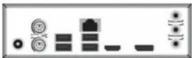
natural_image
Pure electrical circuit lines without any symbols
VGA port(real panel I/O) + DC_IN port(real panel I/O) and DP port (real panel I/O) + ATX_POWER header(internal I/O header) are alternative options of the motherboard.
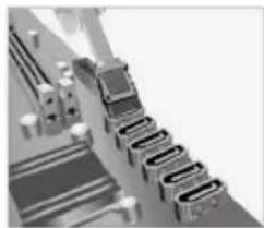
Step 3. Connecting Cables and Power Connectors:
a. Connect the SATA hard drive to its SATA cable
b. Connect SATA power connector to the SATA device
natural_image
Close-up of a mechanical assembly with multiple gears or levers (no visible text or symbols)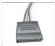
Step 4: Connecting ports on the case:
Once the steps above have been completed, please connect the peripherals such as the keyboard, mouse, monitor, etc. Then, connect the power and turn on the system. Please install all the required software.

Using BIOS
The BIOS (Basic Input and Output System) Setup Utility displays the system's configuration status and provides you options to set system parameters. When you power on the system, BIOS enters the Power-On Self Test (POST) routines, please press or F2 to enter setup. When powering on for the first time, the POST screen may show a "CMOS Settings Wrong" message. Please enter BIOS and choose "Load Default Settings" to reset the default CMOS values. (Changes to system hardware such as different CPU, memories, etc. may also trigger this message.)

The sequence of installation may differ depending on the type of case and devices used.
硬件安装指南
安装步骤
1. 安装记忆体模组:
natural_image
Pure electrical circuit lines without any symbols
natural_image
Interior view of a computer tower case showing internal components like CPU socket and drive dials (no visible text or labels)
natural_image
Pure electrical circuit lines without any symbols
natural_image
Close-up of a mechanical component with multiple grooves and bolts (no visible text or symbols)
4. 连接机箱端口:
BIOS使用设定
natural_image
Pure electrical circuit lines without any symbols
natural_image
Interior view of a computer case showing internal components like CPU socket and drive bays (no visible text or labels)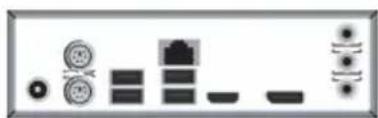
natural_image
Pure electrical circuit lines without any symbols
natural_image
Close-up of a mechanical assembly with multiple components and no visible text or symbols
4단계.케이스의 포트 연결하기:
BIOS사용하기
natural_image
Diagram showing various electronic components and connectors (no text or labels)
natural_image
Interior view of a computer case showing internal components and a small display panel (no visible text or symbols)
natural_image
Close-up of a mechanical component with multiple cylindrical parts (no visible text or symbols)
Menggunakan BIOS
natural_image
Pure electrical circuit lines without any symbols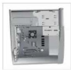
natural_image
Interior view of a desktop computer case showing internal components like CPU socket and drive bays (no visible text or labels)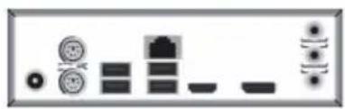
natural_image
Pure electrical circuit lines without any symbols
natural_image
Abstract 3D rendering of a staircase with curved railings and decorative elements (no text or symbols)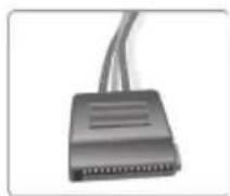
手順 4 ケース上のポートに接続:
BIOSの使用
natural_image
Diagram showing various electronic components and connectors (no text or labels)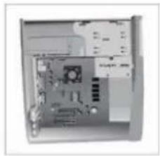
natural_image
Interior view of a computer case with visible CPU socket and drive bays (no text or labels)

natural_image
Close-up of a staircase with ornate metalwork and a ladder (no visible text or symbols)
Sử dụng BIOS


- Federal Communications Commission (FCC)
- Declaration of Conformity
- Preface i
- Brief Introduction 1
- Multi-language Quick Installation Guide 9
- Brief Introduction
- Specifications
- System BIOS
- Form Factor
- Header Pin Definition and Jumper Settings
- I/O Ports
- DC\_IN Port\* (optional)
- PS/2 Mouse (green)
- PS/2 Keyboard (purple)
- USB 3.0 Ports
- LAN Port
- USB 2.0 Ports
- HDMI Port
- VGA Port\* (or DP Port\*) (optional)
- Line-in (blue)
- Line-out (green)
- Microphone (pink)
- Hardware Installation Guide Installation Steps
- Step 1. Installation of Memory Modules:
- Step 2. Installation of Motherboard:
- Step 3. Connecting Cables and Power Connectors:
- Step 4: Connecting ports on the case:
- Using BIOS
- 硬件安装指南
- 安装步骤
- 安装记忆体模组:
- 连接机箱端口:
- BIOS使用设定
- BIOS사용하기
- Menggunakan BIOS
- 手順 4 ケース上のポートに接続:
- BIOSの使用
- Sử dụng BIOS
Brand : ECS
Model : APLD-I2
Category : Tablet