Profile JGP990WELWW - Cooker GE - Free user manual and instructions
Find the device manual for free Profile JGP990WELWW GE in PDF.

User questions about Profile JGP990WELWW GE
0 question about this device. Answer the ones you know or ask your own.
Ask a new question about this device
Download the instructions for your Cooker in PDF format for free! Find your manual Profile JGP990WELWW - GE and take your electronic device back in hand. On this page are published all the documents necessary for the use of your device. Profile JGP990WELWW by GE.
USER MANUAL Profile JGP990WELWW GE
Cooktop Gas Downdraft
Safety Instructions ...2-5
Operating Instructions
Accessories .....7
Controls 8,9
Cookware 9
Electric Ignition 8
Features......6
Griddle....14
Grill Module .....10-13
Surface Burner
Modules 6,8-10
Ventilation System ..... 6, 9
Care and Cleaning
Control Knobs and
Control Panel Seal ..... 15
Grease Jar 15
Griddle Accessory ..... 17
Grill Burner 16
Grill Grate 16
Igniters .....17
Porcelain Burner Basin ..... 17
Porcelain Cooktop ..... 15
Sealed Burner Module .....17
Stainless Steel Surfaces ....15
Vent Grille and Filter ..... 16
Installation
Instructions .....18-29
LP Conversion .....30-33
Troubleshooting
Tips 34,35
Consumer Support
Consumer Support.....40
Product Registration ....37, 38
Warranty 39
Owner's Manual & Installation Instructions
JGP990
Write the model and serial numbers here:
Model # ____
Serial # ____
Find these numbers on a label under the cooktop.
IMPORTANT SAFETY INFORMATION. READ ALL INSTRUCTIONS BEFORE USING.
WARNING!
For your safety, the information in this manual must be followed to minimize the risk of fire or explosion, electric shock, or to prevent property damage, personal injury, or loss of life.
WARNING: If the information in this manual is not followed exactly, a fire or explosion may result, causing property damage, personal injury or death.
— Do not store or use gasoline or other flammable vapors and liquids in the vicinity of this or any other appliance.
- WHAT TO DO IF YOU SMELL GAS
Do not try to light any appliance.
Do not touch any electrical switch; do not use any phone in your building.
Immediately call your gas supplier from a neighbor's phone. Follow the gas supplier's instructions.
If you cannot reach your gas supplier, call the fire department.
— Installation and service must be performed by a qualified installer, service agency or the gas supplier.

text_image
DESIGN CERTIFIED®
IMPORTANT SAFETY NOTICE
The California Safe Drinking Water and Toxic Enforcement Act requires the Governor of California to publish a list of substances known to the state to cause cancer, birth defects or other reproductive harm, and requires businesses to warn customers of potential exposure to such substances.
Gas appliances can cause minor exposure to four of these substances, namely benzene, carbon monoxide, formaldehyde and soot, caused primarily by the incomplete combustion of natural gas or LP fuels. Properly adjusted burners, indicated by a bluish rather than a yellow flame, will minimize incomplete combustion. Exposure to these substances can be minimized by venting with an open window or using a ventilation fan or hood.

SAFETY PRECAUTIONS
Have the installer show you the location of the cooktop gas shutoff valve and how to shut it off if necessary.
■ Have your cooktop installed and properly grounded by a qualified installer, in accordance with the Installation Instructions. Any adjustment and service should be performed only by qualified gas cooktop installers or service technicians.
Be sure your cooktop is correctly adjusted by a qualified service technician or installer for the type of gas (natural or LP) that is to be used. Your cooktop can be converted for use with either type of gas. See the Installation Instructions. Your model is factory adjusted for use with natural gas.
Do not attempt to repair or replace any part of your cooktop unless it is specifically recommended in this manual. All other service should be referred to a qualified technician.
Locate the cooktop out of kitchen traffic path and out of drafty locations to prevent poor burner performance.
Plug your cooktop into a 120-volt grounded outlet only. Do not remove the round grounding prong from the plug. If in doubt about the grounding of the home electrical system, it is your personal responsibility and obligation to have an ungrounded outlet replaced with a properly grounded, three-prong outlet in accordance with the National Electrical Code. Do not use an extension cord with this appliance.
Let the burner grate and other surfaces cool before touching them or leaving them where children can reach them.
Be sure all packaging materials are removed from the cooktop before operating it to prevent fire or smoke damage should the packaging material ignite.
Be sure your cooktop is correctly adjusted by a qualified service technician or installer.
Do not leave children alone or unattended where a cooktop is hot or in operation. They could be seriously burned.
Do not allow anyone to climb, stand or hang on the cooktop.
■ CAUTION: Items of interest to children should not be stored in cabinets above a cooktop—children climbing on the cooktop to reach items could be seriously injured.
■Always keep wooden and plastic utensils and canned food a safe distance away from your cooktop.
■ Always keep combustible wall coverings, curtains or drapes a safe distance from your cooktop.
Never wear loose-fitting or hanging garments while using the appliance. Be careful when reaching for items stored in cabinets over the cooktop. Flammable material could be ignited if brought in contact with flame or hot surfaces and may cause severe burns.
■ Teach children not to play with the controls or any other part of the cooktop.
⚠ WARNING: NEVER use this appliance as a space heater to heat or warm the room. Doing so may result in carbon monoxide poisoning and overheating of the cooktop.
IMPORTANT SAFETY INFORMATION. READ ALL INSTRUCTIONS BEFORE USING.

SAFETY PRECAUTIONS
■Always keep dish towels, dishcloths, pot holders and other linens a safe distance from your cooktop.
- Do not store flammable materials near a cooktop.
Do not store or use combustible materials, gasoline or other flammable vapors and liquids in the vicinity of this or any other appliance.
Do not let cooking grease or other flammable materials accumulate on or near the cooktop.
Do not operate the burner without all burner parts in place.
Do not clean the cooktop with flammable or volatile cleaning fluids.
Do not clean the cooktop when the appliance is in use.
■ Avoid scratching the cooktop with sharp instruments, or with rings and other jewelry.
■ Never use the cooktop as a cutting board.
Do not use water on grease fires. Never pick up a flaming pan. Turn the controls off. Smother a flaming pan on a surface burner by covering the pan completely with a well-fitting lid, cookie sheet or flat tray. Use a multipurpose dry chemical or foam-type fire extinguisher.
Flaming grease outside a pan can be put out by covering it with baking soda or, if available, by using a multipurpose dry chemical or foam-type fire extinguisher.
Do not obstruct the flow of combustion and ventilation air.
■ Leak testing of appliance shall be conducted according to the manufacturer's instructions.
WARNING: To reduce the risk of fire, electrical shock, or injury to persons, observe the following:
A. Use this unit only in the manner intended by the manufacturer. If you have questions, contact the manufacturer.
B. Before servicing or cleaning the unit, switch power off at service panel.
C. When cutting or drilling into wall or ceiling, do not damage electrical wiring and other hidden utilities.
D. Ducted fans must always be vented to the outdoors.
E. To reduce the risk of fire, use only metal ductwork.
WARNING: To reduce the risk of a cooktop grease fire:
A. Keep fan, filters and grease-laden surfaces clean.
B. Always turn vent ON when cooking at high heat.
C. Use high settings on cooktop only when necessary. Heat oil slowly on low to medium setting.
D. Don't leave the cooktop unattended when cooking.
E. Always use cookware and utensils appropriate for the type and amount of food being prepared.
CAUTION: For general ventilating use only. Do not use to exhaust hazardous or explosive materials and vapors.

COOK MEAT AND POULTRY THOROUGHLY...
Cook meat and poultry thoroughly—meat to at least an INTERNAL temperature of 160^ F and poultry to at least an INTERNAL temperature of 180^ F. Cooking to these temperatures usually protects against foodborne illness.
⚠ WARNING!
SURFACE BURNERS
Use proper pan size—avoid pans that are unstable or easily tipped. Select cookware having flat bottoms large enough to cover burner grate. To avoid spillovers, make sure cookware is large enough to contain the food properly. This will both save cleaning time and prevent hazardous accumulations of food, since heavy spattering or spillovers left on cooktop can ignite. Use pans with handles that can be easily grasped and remain cool.
■ Always use the LITE position when igniting the top burners and make sure the burners have ignited.
Never leave the surface burners unattended at high flame settings. Boilovers cause smoking and greasy spillovers that may catch on fire.
Use only dry pot holders—moist or damp pot holders on hot surfaces may result in burns from steam. Do not let pot holders come near open flames when lifting cookware. Do not use a towel or other bulky cloth in place of a pot holder. Such cloths can catch fire on a hot burner.
When using glass cookware, make sure it is designed for cooktop cooking.
To minimize the possibility of burns, ignition of flammable materials and spillage, turn cookware handles toward the side or center of the cooktop without extending over adjacent burners.
■Always turn the surface burner controls off before removing cookware.
Carefully watch foods being fried at a high flame setting.
■Always heat fat slowly and watch as it heats.
Do not leave any items on the cooktop. The hot air from the vent may ignite flammable items and will increase pressure in closed containers, which may cause them to burst.
If a combination of oils or fats will be used in frying, stir together before heating or as fats melt slowly.
Do not use a wok on the cooking surface if the wok has a round metal ring that is placed over the burner grate to support the wok. This ring acts as a heat trap, which may damage the burner grate and burner head. Also, it may cause the burner to work improperly. This may cause a carbon monoxide level above that allowed by current standards, resulting in a health hazard.
- Foods for frying should be as dry as possible. Frost on frozen foods or moisture on fresh foods can cause hot fat to bubble up and over the sides of the pan.
Use the least possible amount of fat for effective shallow or deep-fat frying. Filling the pan too full of fat can cause spillovers when food is added.
Use a deep fat thermometer whenever possible to prevent overheating fat beyond the smoking point.
■ Never try to move a pan of hot fat, especially a deep fat fryer. Wait until the fat is cool.
Do not flame foods on the cooktop. If you do flame foods under the hood, turn the fan on.
Do not leave plastic items on the cooktop—they may melt if left too close to the vent. - Keep all plastics away from the surface burners.
If you smell gas, turn off the gas to the cooktop and call a qualified service technician. Never use an open flame to locate a leak.
To avoid the possibility of a burn, always be certain that the controls for all burners are at the off position and all grates are cool before attempting to remove them.
Never clean the cooktop surface when it is hot. Some cleaners produce noxious fumes and wet cloths could cause steam burns if used on a hot surface.
■ Never leave jars or cans of fat drippings on or near your cooktop.
Do not use aluminum foil under burner grate. Misuse could result in a fire hazard or damage to the cooktop.
Do not cover or block the area around the cooktop knobs. This area must be kept clear for proper ventilation and burner performance. - Clean only parts listed in this Owner's Manual.

READ AND FOLLOW THIS SAFETY INFORMATION CAREFULLY.
SAVE THESE INSTRUCTIONS
Features of your cooktop.
Throughout this manual, features and appearance may vary from your model.

text_image
Diagram of a portable air conditioner unit with labeled components including ventilation grilles, fan blades, and switches.Feature Index
1 Grill Module (optional)
2 Vent (fan operates automatically when grill is in use)
3 Vent Filter (located below the vent grille)
4 Cast-Iron Burner Grate
5 Surface Burners
6 Surface Burner Controls
7 Vent Control
Cooktop accessories. ge.com
Throughout this manual, features and appearance may vary from your model.

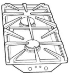
natural_image
Simple line drawing of a rectangular block with horizontal striped texture (no text or symbols)Grill Model JXGG90L
Consists of a black grill grate and a grill burner.

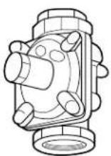
natural_image
Technical line drawing of a portable gas stove with four panes and a central vent (no text or symbols)Sealed Burner Module Models JXGB90B (black), JXGB90S (stainless steel) and JXGB90W (white)
The grill assembly can be removed and a sealed burner module installed.
NOTE: Optional surface burner module (JXGB90) can replace the grill assembly. Burners supplied with cooktop and optional module air shutters have been adjusted for compatibility on both sides.

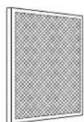
natural_image
Simple line drawing of a tray with four circular cutouts and three horizontal bars (no text or symbols)Griddle Model JXGL90L
Can be used only with the grill burner. Self-draining griddle makes many favorite foods easier to fix. Family-sized surface lets you cook several pancakes, hamburgers or grilled sandwiches at the same time.
Using the gas surface burners.
Throughout this manual, features and appearance may vary from your model.
Electric Ignition
Your surface burners are lit by electric ignition, eliminating the need for standing pilots with constantly burning flames.
In case of a power outage, you can light the surface burners on your cooktop with a match. Hold a lit match to the burner, then turn the control knob to the high position. Use extreme caution when lighting the burners this way.
Surface burners in use when an electrical power failure occurs will continue to operate normally.
IN CASE OF A POWER FAILURE, THE VENTILATION SYSTEM WILL NOT OPERATE. DO NOT USE THE GRILL MODULE OR GRIDDLE IF THE VENTILATION SYSTEM IS NOT OPERATIONAL.
natural_image
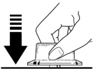
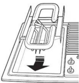
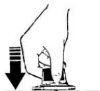
Illustration of hands pressing down on a mechanical component with a downward arrow (no text or symbols)Push the control knob down and turn it to the LITE position.
How to Light a Gas Surface Burner
Push the control knob down and turn it to the LITE position.
You will hear a little clicking noise—the sound of the electric spark igniting the burner.
After the burner ignites, turn the knob to adjust the flame size.
To turn a burner off, turn the knob clockwise, as far as it will go, to the OFF position.
If the flame is too low at the setting, the valve can be adjusted. Refer to Flames too high or too low at the LOW setting in the Troubleshooting Tips section.

How to Select Flame Size
For safe handling of cookware, never let the flames extend up the sides of the cookware.
Watch the flame, not the knob, as you reduce heat. The flame size on a gas burner should match the cookware you are using.
Any flame larger than the bottom of the cookware is wasted and only serves to heat the handle.
If the burner has not been used recently, the flames may make a loud noise. This is normal, and it should dissipate after 4 to 5 minutes.
Before Lighting a Gas Burner
■ Make sure all grates on the cooktop are in place before using any burner.
■ Only surface burners may be used on the right side.
After Lighting a Gas Burner
Do not operate the burner for an extended period of time without cookware on the grate. The finish on the grate may chip without cookware to absorb the heat.
- Check to be sure the burner you turn on is the one you want to use.
Be sure the burners and grates are cool before you place your hand, a pot holder, cleaning cloths or other materials on them.
When trying to simmer delicate foods, use the right side of the unit for best results. The LO setting on the left side is hotter to accommodate the grill module. If you find that the LO setting is too hot, you can adjust the valve. See the Troubleshooting Tips section.
Do not allow large pans to extend over the control knobs. Heat trapped between large pans and control knobs could cause possible damage to the control knobs.

Use a flat-bottomed wok.
Wok This Way
We recommend that you use a flat-bottomed wok, available at your local retail store.
Only a flat-bottomed wok should be used. Do not use a flat-bottomed wok with a wok holder.
Do not use a flat-bottomed wok on a support ring. Placing the ring over the burner or grate may cause the burner to work improperly, resulting in carbon monoxide levels above allowable current standards. This could be dangerous to your health.
Cookware
Use large diameter cookware on rear burners.
Aluminum: Medium-weight cookware is recommended because it heats quickly and evenly. Most foods brown evenly in an aluminum skillet. Use saucepans with tight fitting lids when cooking with minimum amounts of water.
Enamelware: Under some conditions, the enamel of some cookware may melt. Follow cookware manufacturer's recommendations for cooking methods.
Glass: There are two types of glass cookware: those for oven use only and those for cooktop cooking (saucepans, coffee and teapots). Glass conducts heat very slowly.
Cast Iron: If heated slowly, most skillets will give satisfactory results.
Heatproof Glass-Ceramic: Can be used for either surface or oven cooking. It conducts heat very slowly and cools very slowly. Check cookware manufacturer's directions to be sure it can be used on a gas cooktop.
Stainless Steel: This metal alone has poor heating properties and is usually combined with copper, aluminum or other metals for improved heat distribution. Combination metal skillets usually work satisfactorily if they are used with medium heat as the manufacturer recommends.
Using the downdraft vent system.

text_image
OFF LO MED HIHow to Operate the Downdraft Vent System
The built-in vent system helps remove cooking vapors, odors and smoke from foods prepared on the cooktop.
To turn on the vent fan, use the vent control switch on the control panel.
- Turn the vent fan speed control knob to HI, MED or LO as needed.
NOTE: Even if the fan switch is in the OFF position, the fan will turn on automatically and operate continuously while the grill burner module is in use.
Continuous use of the vent system while cooking helps keep the kitchen comfortable and less humid, reducing cooking odors and soiling moisture that normally creates a frequent need for cleaning.
At the HI fan speed setting, it is normal for the nearby burner flames to be drawn toward the vent grille. If cooking performance is affected, then use a lower fan speed setting.
IN CASE OF A POWER FAILURE, THE VENTILATION SYSTEM WILL NOT OPERATE. DO NOT USE THE GRILL MODULE OR GRIDDLE IF THE VENTILATION SYSTEM IS NOT OPERATIONAL.
Surface burner and grill modules.
Throughout this manual, features and appearance may vary from your model.
natural_image
Line drawing of a gas stove with cooling fans and a down arrow indicating airflow (no text or symbols)Sealed Burner Module
To Install the Sealed Burner Module:
- Make sure that all control knobs are set to OFF.
- Clean the cooktop basin to remove any grease accumulation. See the Care and Cleaning the Cooktop section.
-
With the back of the burner module tilted up and the two round openings and three pins facing toward the front, insert the module in the cooktop basin.
-
Slide the burner module forward until the pins start to engage the white slotted receptacle.
- Lower the back of the module into place and carefully slide it forward until the pins are fully engaged.
- Place the burner caps on the burners. Carefully place the grate onto the module with the two tabs on the underside toward the center of the cooktop.
To Remove the Sealed Burner Module:
- Make sure that all control knobs are set to OFF and that the cooktop is cool.
-
Lift up the edge of the burner module until the bottom of the module clears the edge of the basin.
IMPORTANT: Do not lift the module too high while it is still connected—you could damage the ignitor rods and mixer tubes. -
Hold the module by the sides and pull it away from the slotted receptacle and brass orifices. Lift it out of the basin when it is completely unplugged.
- Do not store or stack modules where they could fall or be damaged.
NOTE: The optional sealed burner module JXGB90 can replace the grill burner assembly.
natural_image
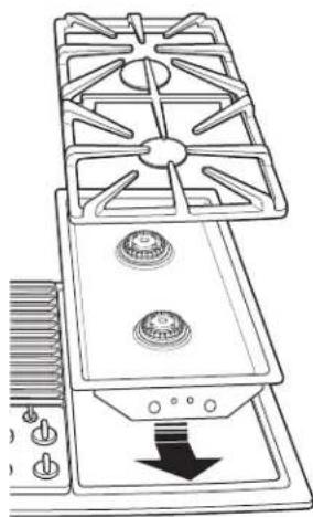
Diagram of a mechanical device with a downward arrow indicating force or motion (no text or symbols present)Grill Module
The grill consists of a black grill grate and the grill burner. Only install the grill on the left side of your cooktop.
To Install the Grill Module:
- Make sure that all control knobs are set to OFF.
- Position the grill burner with the two round tubes and three pins facing the front.
-
Slide the grill burner forward until the pins and ignitors are engaged in the white slotted receptacle; then lower the burner until it rests on the mounting pins.
-
Carefully place the grill grate on the cooktop. The grate is designed to fit one way only. See the illustration.
NOTE: Before using the grill for the first time, heat the grill burner to remove the protective shipping coating. Heat the grill burner on HI for 10 minutes and use the vent system to remove any additional smoke during cooling.

natural_image
Diagram of a refrigerator with ventilation slots and control buttons (no text or symbols)To Remove the Grill Module:
- Make sure that all control knobs are set to OFF and all grill components are cool.
- Remove the grill grate.
-
Lift the grill burner up slightly and pull it away from the white slotted receptacle and brass orifices. Lift it out of the basin when it is completely unplugged.
-
Do not store or stack modules where they could fall or be damaged.
NOTE: The optional sealed burner module JXGB90 can replace the grill burner assembly.
Using the Grill
- The vent fan will turn on automatically and operate continuously while the grill burner module is in use.
- Before using the grill for the first time, wash grill grate in hot soapy water. Rinse and dry.
- Precondition grate by brushing with vegetable oil or spraying with a non-stick coating such as Pam®. Do this every time before you grill.
- For easier clean-up, spray grate and burner basin with a non-stick coating.
- Use nonmetallic spatulas or utensils to prevent damaging the non-stick grill grate finish.
- Preheat the grill on high for 5 to 10 minutes. Preheating improves the flavor and appearance of meats and quickly sears the meat to help retain the juices.
- Excessive amounts of fat should be trimmed from meats. Some fat is necessary to produce the smoke needed for that smoked "outdoor" flavor. However, excessive fat can create cleaning and flare-up problems.
-
Allowing excessive amounts of grease or drippings to constantly flame voids the warranty on the grill grate. Excessive flare-ups indicate that either the grill interior needs to be cleaned, excessive amounts of fat are in the meat or that the meat was not properly trimmed.
-
Grease drippings will occasionally ignite to produce harmless puffs of flame for a second or two. This is a normal part of the cooking process.
- Never leave the grill unattended during operation.
IMPORTANT:
IN CASE OF A POWER FAILURE, THE VENTILATION SYSTEM WILL NOT OPERATE. DO NOT USE THE GRILL MODULE OR GRIDDLE IF THE VENTILATION SYSTEM IS NOT OPERATIONAL.
- Do not use aluminum foil inside the grill area.
- Do not use charcoal or wood chips in the grill area.
- Do not allow burner basin to become overloaded with grease. Clean after each use.
- Do not cover grate completely with meat. Leave air space between each steak, etc., to allow proper ventilation as well as to prevent flare-ups.
- Do not use cooking pots, pans, skillets, etc., on the grill grate.
Should a Sustained Flare-Up Occur:
- Use the vent control to turn the fan on.
- Immediately turn the grill control knobs to the OFF position.
- Remove the meat from the grill.
Grilling.
Grilling Tips
- With your grill, any food you've considered "at its best" when prepared outdoors can now be prepared indoors with less fuss and great flavor.
- The following suggestions are good rules to follow and will increase your enjoyment of the equipment. Be sure to follow directions in this manual for using the grill.
- Suggested cooking times and control settings are approximate due to variations in meats. Experience will quickly indicate cooking times as well as which settings work best.
- For best results, buy top-grade meat. Meat that is at least 3/4-inch thick will grill better than thinner cuts.
-
For the attractive "branded" look on steaks, be sure the grill is preheated. Allow one side of the meat to cook to the desired doneness, or until the juices appear on the top surface, before turning. Turn steaks and hamburgers just once. Moving the food around causes loss of juices.
-
When basting meats or applying sauces to foods, remember that excessive amounts wind up inside your grill and do not improve the food flavor. Apply sauces during the last 15 to 20 minutes of cooking time unless the recipe specifies otherwise. Sugar-based marinade (for example, barbecue sauce) will caramelize on grill grate and will create a cleaning chore.
• There are many meat marinades which will help tenderize less expensive cuts of meat for cooking on the grill. - Certain foods, such as poultry and non-oily fish, may need some extra fat. Brush with oil or melted butter occasionally while grilling.
- Use tongs with long handles or spatulas for turning meats. Do not use forks because these pierce the meat, allowing juices to be lost.
• To help retain meat juices, salt after turning meat or after cooking is completed. - Score the fat on the edges of steaks but do not cut into the meat to prevent curling while cooking.
Preheat the grill on high for 5 to 10 minutes for best flavor.
Type Control Setting Cooking Time Procedure
| Meat | |||
| Steak (1/2”-3/4”) | |||
| Rare HI 6 to 10 minutes Turn after 3 to 5 minutes.† | |||
| Medium HI 10 to 16 minutes Turn after 5 to 8 minutes. | |||
| Well HI 21 to 24 minutes Turn after 6 to 12 minutes. | |||
| Steak (1”-13⁄4”) | |||
| Rare HI 14 to 24 minutes Turn after 7 to 12 minutes.† | |||
| Medium HI 18 to 30 minutes Turn after 9 to 15 minutes. | |||
| Well HI 24 to 34 minutes Turn after 12 to 17 minutes. | |||
| Hamburgers (3-4 oz.) | Medium | 20 to 25 minutes | Turn after half the time. |
| Pork chops | Medium | 20 to 30 minutes | Turn occasionally. |
| Fully cooked smoked pork chops | Medium | 10 to 15 minutes | Turn after half the time. |
| Ham slices | Medium | 15 to 20 minutes | Turn after half the time. |
| Pork ribs | Medium | 50 to 65 minutes | Turn occasionally. Brush with barbecue sauce during the last 15 minutes. |
| Fully cooked sausages | |||
| Hot dogs, brats | HI 7 to 12 minutes | Turn occasionally. | |
| Polish | HI 13 to 16 minutes | Turn occasionally. | |
| Fresh sausages | |||
| Links | Medium | 15 to 25 minutes | Turn occasionally. |
| Patties (3” diameter) | Medium | 15 to 20 minutes | Turn after half the time. |
| Italian sausage | Medium | 25 to 30 minutes | Pierce casing with a fork. Turn once. |
| Lamb chops | Medium | 20 to 30 minutes | Turn occasionally. Brush with glaze, if desired. |
| Poultry | |||
| Chicken | |||
| Pieces: bone-in | Medium | 35 to 50 minutes | Turn occasionally. |
| Boneless breasts | Medium | 25 to 35 minutes | Turn occasionally. |
| Wings | Medium | 25 to 35 minutes | Turn occasionally. |
| Cornish hen (halved) | Medium | 35 to 45 minutes | Turn occasionally. |
| Fish | |||
| Small, whole (1”) | Medium | 15 to 20 minutes | Brush with butter. Turn after half the time. |
| Steaks (1”) | Medium | 20 to 25 minutes | Brush with butter. Turn after half the time. |
| Fillets—with skin on (1/2”) | Medium | 10 to 15 minutes | Start skin side down. Brush with butter. Turn after half the time. |
| Shrimp (skewered) | Medium | 10 to 20 minutes | Turn and brush with butter or marinade frequently. |
| Bread | |||
| Garlic bread | Medium | 4 to 6 minutes | Turn after half the time. |
| Hot dog or hamburger buns | Medium | 1 to 2 minutes | Turn after half the time. |
† The U. S. Department of Agriculture says "Rare beef is popular, but you should know that cooking it to only 140°F means some food poisoning organisms may survive." (Source: Safe Food Book. Your Kitchen Guide. USDA Rev. June 1985.)
Griddle.
Griddle Accessory
Using the griddle:
- Before the first use, wash your new griddle in hot soapy water, rinse and dry. Then "condition" the surface by wiping on a thin coating of cooking oil or shortening. Remove excess oil or shortening by wiping again with another paper towel.
- Insert grill burner. DO NOT use grill grate.
-
Place griddle over grill burner so that the drain holes are in front. This will permit excess grease to be collected in the grease container.
-
Preheat the griddle 5 to 10 minutes at the specified setting as noted in the Griddle Guide.
- Use non-metallic spatulas or utensils while cooking to prevent damaging the finish.
IMPORTANT:
IN CASE OF A POWER FAILURE, THE VENTILATION SYSTEM WILL NOT OPERATE. DO NOT USE THE GRILL MODULE OR GRIDDLE IF THE VENTILATION SYSTEM IS NOT OPERATIONAL.
Griddle Guide
NOTE: These are suggested guides for control settings and times. Factors such as low gas pressure may affect the times and control settings that provide the best results. Preheat 5 to 10 minutes at specified setting.
| Food Item Setting Time First Side Time Second Side | |||
| Bacon Medium 4-5 minutes | 3-4 minutes | ||
| Buns | HI | 2-3 minutes | |
| Eggs | Medium 2-3 | minutes | 1 minute |
| Fish sticks (frozen) | Medium 7-8 | minutes 5-7 minutes | |
| Ham slice | Medium 6-7 | minutes 5-6 minutes | |
| Hamburgers | Medium 5-7 | minutes 4-6 minutes | |
| Hot dogs | HI | 5 minutes | 5 minutes |
| French toast | HI | 2-4 minutes 2-3 minutes | |
| Grilled cheese sandwiches | HI | 2-3 minutes 2-3 minutes | |
| Pancakes | HI | 1-2 minutes 1-2 minutes | |
| Sausage patties | Medium 6-8 | minutes 4-5 minutes | |
NOTE: The griddle uses the grill burner module, so the fan will turn on automatically and operate continuously while the griddle accessory is in use.
Care and cleaning of the cooktop. ge.com
Before Cleaning
Before cleaning any part of your cooktop, be sure all controls are off and DISCONNECT ELECTRICAL POWER TO THE COOKTOP at the fuse box or circuit breaker panel, or pull the cooktop power
plug, located beneath the cooktop and inside the cabinets.
Do not operate the cooktop without all parts in place.
Control Knobs and Control Panel Seal
After grilling there may be soot on the knobs and control panel seal. This soot can be removed by scrubbing with a plastic scrubber and mild dishwashing detergent. The control knobs may be removed for cleaning.
Wash the knobs in soap and water but do not soak. Avoid getting water down into the knob stem holes.
To remove a knob, pull it straight up.
Wipe with a sponge, damp cloth or paper towel. Do not scrub with steel wool pads or abrasive cleansers.
To replace a knob, match the flat part of the knob opening with the flat side of the shaft.

Grease Jar
A grease jar is located below the grill basin pan under the countertop. Check periodically to prevent spillovers. Unscrew and remove.
If the jar is broken, replace with any heat tempered jar, such as a canning jar, that has a wide mouth screw neck.
Porcelain Cooktop
The porcelain enamel finish is sturdy but breakable if misused. This finish is acid-resistant. However, any acidic foods spilled (such as fruit juices, tomato or vinegar) should not be permitted to remain on the finish.
For other spills, such as fat spatterings, wash with soap and water or cleansing powders after the surface has cooled. Rinse well. Polish with a dry cloth.
If acids spill on the cooktop while it is hot, use a dry paper towel to wipe it up right away. When the surface has cooled, wash with soap and water or cleansing powders. Rinse well.
Stainless Steel Surfaces
Do not use a steel wool pad; it will scratch the surface.
To clean the stainless steel surface, use warm sudsy water or a stainless steel cleaner or polish. Always wipe the surface in the direction of the grain. Follow the cleaner instructions for cleaning the stainless steel surface.
To inquire about purchasing stainless steel appliance cleaner or polish, or to find the location of a dealer nearest you, please call our toll-free number:
National Parts Center 800.626.2002
ge.com
Care and cleaning of the cooktop.
natural_image
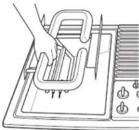
Line drawing of a hand using a tool to clean or install a kitchen appliance on an induction cooktop (no text or symbols)Grill Burner
The grill burner should be cleaned after each use. It can be cleaned with a non-abrasive pad or in the dishwasher. Rinse and dry thoroughly before using again. For heavy soil, the burner should be cleaned first with a soapy steel wool pad, rinsed and dried. Then it can be cleaned in a self-cleaning oven for two hours.
NOTE: Check to be sure all burner ports are open. To open clogged ports, insert a twist tie directly into each port.
natural_image
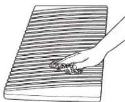
Hand holding a small object over a striped rectangular surface (no text or symbols)Grill Grate
The grate should be cleaned after each use. It can be cleaned with detergent and a plastic scrubber, such as Tuffy, or washed in the dishwasher if burned-on residue is first removed. For heavy soil, the grate can be soaked in hot, soapy water mixed with household ammonia.
Do not use metal brushes or abrasive scouring pads or other scrubbers intended to clean outdoor grills. These will remove the finish as well as scratch the grate. Do not clean in a self-cleaning oven or use oven cleaners on the grate.

natural_image
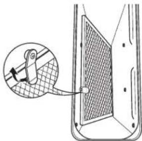
Illustration of a hand using a tool to cut or remove a component, with no visible text or symbols.Vent Grille and Filter
Vent Grille: The vent grille lifts off easily. Wipe clean or wash in the sink with mild household detergents.
NOTE: On models with a white vent grille, stubborn stains may be removed by soaking the grille in a 50/50 mix of bleach and water overnight. After cleaning, rinse the grille thoroughly and dry it before replacing.
Filter: Turn off the fan before removing. Turn the filter retainer clip to remove the filter. The filter is a permanent type and should be cleaned when soiled. Clean in the sink with warm water and liquid dishwashing detergent.
IMPORTANT: Do not operate the fan without the filter. The filter should always be placed at an angle. As you face the front of the cooktop, the top of the filter should rest against the left side of the vent opening and the bottom of the filter should rest against the right side of the ventilation chamber at the bottom. If the filter is flat against the fan wall, ventilation effectiveness is reduced.
Ventilation Chamber: This area, which houses the filter, should be cleaned in the event of spills or whenever it becomes coated with a film of grease. The ventilation chamber may be cleaned with a paper towel, damp cloth or sponge and a mild household detergent or cleanser.
natural_image
Diagram showing a mechanical component with a magnified inset highlighting a gear mechanism (no text or symbols present)When replacing the filter, make sure it rests, at an angle, on the supports in the vent opening. Latch it in place.
natural_image
Technical line drawing of a rectangular industrial or gas stove with radial fins and central hub (no text or symbols)Igniters Electrodes
It is important to keep igniter port openings on burners clear and free of obstructions to avoid ignition failure and possible gas buildup. If the port openings are blocked, use a twist tie or paper clip to remove any clogs in the burner slits.
This small metal rod in the burner produces the spark and must be kept clean and dry to properly ignite the gas. Use a dry paper towel or scrub pad to keep the electrode clean.
Griddle Accessory
DO NOT immerse a hot griddle in cold water.
Once the griddle has cooled, wash with soap or detergent in hot water in the sink. Be sure to remove all food residue before cooking on the griddle again.
Remove stubborn spots with a plastic scouring pad. For best results, use only those cleaning products which are recommended for use when cleaning non-stick surfaces. Do not use steel wool or coarse scouring pads.
DO NOT wash in a dishwasher.
Sealed Burner Module
Cooktop Surface:
To prevent the cooktop from discoloring or staining:
- Clean the cooktop after each use.
- Wipe up acidic or sugary spills as soon as the cooktop has cooled, because these spills may discolor the porcelain.
Sealed Burners:
The sealed burners of your cooktop are secured to the cooktop module and are not designed to be removed. Since the burners are sealed into the module, boilovers or spills will not seep underneath the cooktop. However, the burner heads should be cleaned after each use.
Burner Grate:
The grate must be properly positioned before cooking. Improper installation of the grate may result in chipping of the cooktop.
Do not operate burners without a pan on the grate. The grate's porcelain finish may chip without a pan to absorb the heat from the burner flame.
Although the burner grate is durable, it will gradually lose its shine and/or discolor, due to the high temperatures of the gas flame.
Burner Caps:
Lift off when cool. Wash burner caps in hot, soapy water and rinse with clean water. You may scour with a plastic scouring pad to remove burned-on food particles.
Porcelain Burner Basin
This area is located under the grill and surface burners and should be cleaned after each use of the grill.
To remove light soil, clean with soapy water or with a cleaner such as 409 ^® . For easier cleanup, soak paper towels in a household cleanser, lay in the burner basin and soak for at least a half hour or longer.
To remove moderate soil, scrub with Comet ^® , Bon Ami ^® , a soft scrub cleanser or plastic scrubber.
To remove stubborn soil, spray with an oven cleaner. Let soak overnight. Wipe clean. Rinse and dry.
Installation Gas Downdraft Cooktop Instructions
If you have questions, call 800.GE.CARES (800.432.2737) or visit our Website at: ge.com
In the Commonwealth of Massachusetts:
- This product must be installed by a licensed plumber or gas fitter.
- When using ball-type gas shut-off valves, they shall be the T-handle type.
- A flexible gas connector, when used, must not exceed 3 feet.
BEFORE YOU BEGIN
Read these instructions completely and carefully.
- IMPORTANT – Save these instructions for local inspector's use.
- IMPORTANT – Observe all governing codes and ordinances.
- Note to Installer – Be sure to leave these instructions with the Consumer.
- Note to Consumer – Keep these instructions for future reference.
- Proper installation is the responsibility of the installer.
- Product failure due to improper installation is not covered under the Warranty.
FOR YOUR SAFETY
If You Smell Gas:
- Open windows.
- Don't touch any electrical switches.
- Extinguish any open flame.
- Immediately call your gas supplier.
Do not store or use gasoline or other flammable vapors and liquids in the vicinity of this or any other appliance.

WARNING
Before beginning
the installation, switch power off at the service panel and lock the service disconnecting means to prevent power from being switched on accidentally. When the service disconnecting means cannot be locked, securely fasten a prominent warning device, such as a tag, to the service panel.
IMPORTANT SAFETY INSTRUCTIONS
The cooktop has been design-certified by CSA International. As with any appliance using gas and generating heat, there are certain safety precautions you should follow. You'll find these precautions in the Important Safety Instructions section in the front of this Owner's Manual. Read them carefully.
- Be sure your cooktop is installed properly by a qualified installer or service technician.
- The cooktop must be electrically grounded in accordance with local codes, or in their absence, with the National Electrical Code ANSI/NFPA No. 70—Latest Edition.
- Installation of this cooktop must conform with local codes, or in the absence of local codes, with the National Fuel Gas Code ANSI Z223.1/NFPA 54—Latest Edition.
- Improper installation, adjustment, alteration, service or maintenance can cause injury or property damage. Refer to this manual. For assistance or additional information, consult a qualified installer, service agency, manufacturer (dealer) or the gas supplier.
- Disconnect electrical supply before servicing.
- Never reuse old flexible connectors. The use of old flexible connectors can cause gas leaks and personal injury. Always use NEW flexible connectors when installing a gas appliance.
- Make sure the wall coverings around the cooktop can withstand heat generated by the cooktop up to 200^ .
- Avoid placing cabinets above the cooktop.
- If cabinets are placed above the cooktop, allow a minimum clearance of 30" between the cooking surface and the bottom of protected cabinets.
- A non-combustible material must be installed on the under side of the cabinet. Use a flame retardant millboard at least 1/4"(6.3 mm) thick, or gypsum board at least 3/16"(4.7 mm) thick, covered with 28 gauge sheet steel or 0.020"(5 mm) thick copper. The maximum depth of cabinets above the cooktop is 13"(33 cm).
UNPACK YOUR COOKTOP
PARTS INCLUDED
• Cooktop with side hold-down bolts (2)
- Blower assembly
- Blower plenum
- Vent guard and mounting nuts (4)
• Sheet metal screws (7)
- Vent grille
- Vent filter
- Sealed burner module
- Sealed burner grate
- Grease jar
• Sealed burner caps (2)
• Gas pressure regulator
- Attached 120-volt grounded plug cord
• LP Conversion (attached to the electrical box)

Grease
Jar

Sheet Metal Screws (7)
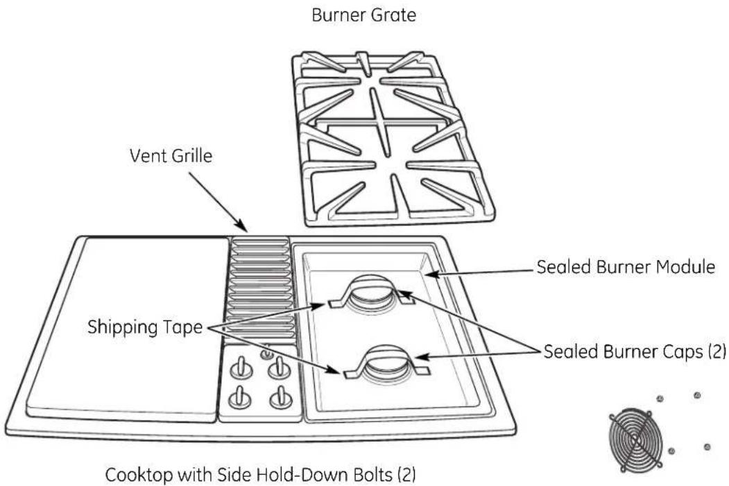
text_image
Burner Grate Vent Grille Shipping Tape Sealed Burner Module Sealed Burner Caps (2) Cooktop with Side Hold-Down Bolts (2)Vent Guard and Mounting Nuts (4)
Gas
Pressure
Regulator
Vent Filter
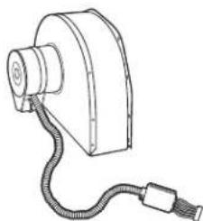
natural_image
Line drawing of a mechanical device with a coiled cable and connector (no text or symbols)Blower Assembly

Blower Plenum
PREPARATION
TOOLS AND PARTS NEEDED
• Large flat-blade screwdriver
• Phillips screwdriver
- 3/8"socket and ratchet
- Saw
- Carpenter's square
- Pipe wrench
• Gas line shut off valve
- Pipe joint sealant for use with gas connections that resists action of LP gas
For flexible connection where local codes permit:
- Flexible metal tubing (same 3/4" or 1/2" I.D. as gas supply line)
- Flare union adapter for connection to supply line (3/4" NPT × 3/4" I.D. or 1/2" NPT × 1/2" I.D.)
- Flare union adapter for connection to regulator (1/2" NPT × 3/4" I.D. or 1/2" I.D.)
For rigid connection:
- Pipe fittings as required
IMPORTANT
Motor Clearance—Provide 2"min. (5.1 cm) cabinet clearance to motor for cooling purpose.
NOTE: Where possible, 6"(15.2 cm) is recommended for motor/blower service.
Side Clearance—Grills installed near a side wall should allow a minimum clearance of 8"(20.3 cm).
You must allow room enough to remove and empty grease container(s).
CAUTION: Warranty is void on equipment installed other than as recommended by GE. Recommended wall caps and transitions must be used for proper operation and installation.
PREPARING FOR INSTALLATION


text_image
4½"10.64 cm 18½" 47 cm Minimum Clearance 2" 5.08 cm Minimum Clearance Appliance Pressure Regulator Grease Container 14½" 36.83 cm 12½" 32.7 cm* Blower may be rotated for horizontal or vertical direction by loosening nuts around blower inlet. Accessible inside ventilation chamber.
PREPARATION
MINIMUM SPACING REQUIREMENT
When installing a double bay downdraft cooktop in combination with another downdraft cooktop, maintain the minimum spacing between units as shown below. Installing them too close will affect cooking performance.
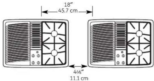
text_image
18" 45.7 cm 43⁄8" 11.1 cm1 INSTALLING CABINETS OVER YOUR COOKTOP
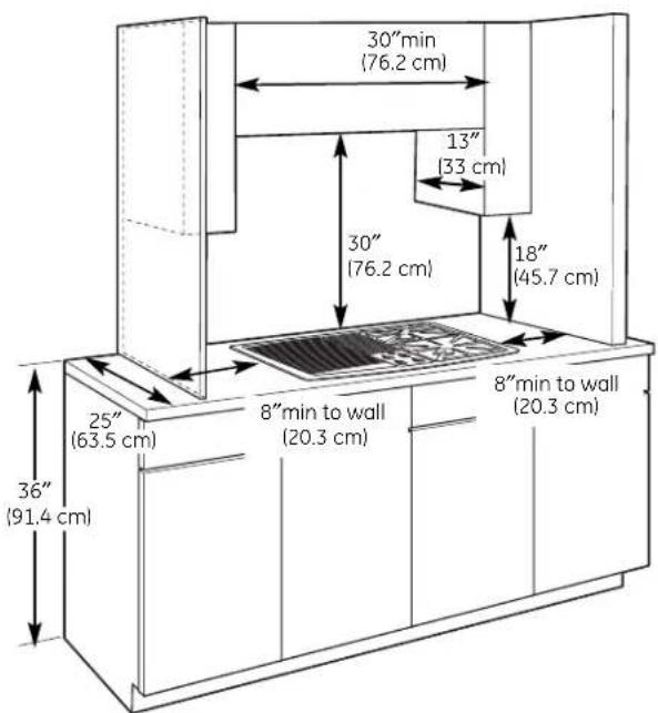
text_image
30" min (76.2 cm) 13" (33 cm) 30" (76.2 cm) 18" (45.7 cm) 25" (63.5 cm) 8" min to wall (20.3 cm) 8" min to wall (20.3 cm) 36" (91.4 cm)Avoid placing cabinets above the cooktop unit, if possible, in order to reduce the hazards caused by reaching over heated surface units.
If the cabinets are installed above the cooktop, allow a minimum 30"(76.2 cm) clearance between the cooking surface and the bottom of the cabinet.
A non-combustible material must be installed on the under side of the cabinet. Use a flame retardant millboard at least 1/4"(6.3 mm) thick, or gypsum board at least 3/16"(4.7 mm) thick, covered with 28 gauge sheet steel or 0.020"(5 mm) thick copper. The maximum depth of cabinets above the cooktop is 13"(33 cm).
EXCEPTION: Installation of a listed microwave oven or cooking appliance over the cooktop shall conform to the installation instructions packed with that appliance.
Working areas adjacent to the cooktop should have an 18"(45.7 cm) minimum clearance between the countertop and the bottom of the cabinet. If the clearance is less than 18"(45.7 cm), the adjacent cabinets should be at least 8"(20.3 cm) from the side of the cooktop.
PREPARATION
2 PREPARING THE COUNTERTOP
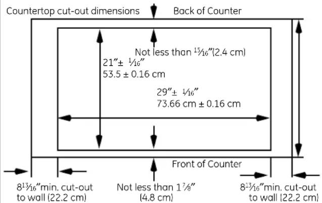
text_image
Countertop cut-out dimensions Back of Counter Not less than 15/16"(2.4 cm) 21" ± 1/16" 53.5 ± 0.16 cm 29" ± 1/16" 73.66 cm ± 0.16 cm Front of Counter 81/16"min. cut-out to wall (22.2 cm) Not less than 17/8" (4.8 cm) 81/16"min. cut-out to wall (22.2 cm)Cut out the opening as shown in the diagram. Measure carefully when cutting the countertop, making sure the sides of the opening are parallel and the front and rear cuts are exactly perpendicular to the sides.
The front of the opening must clear the front support rail on the cabinet, and the rear of the opening must clear the rear support of the cabinet.
Chamfer all exposed edges of decorative laminate to prevent damage from chipping.
Radius corners of cutout and file to ensure smooth edges and prevent corner cracking.
Rough edges inside corners which have not been rounded and forced fit can contribute to cracking of the countertop laminate.
Countertop must be supported within 3"(7.6 cm) of cutout.
3 GAS AND ELECTRICAL LOCATION
The position of the electrical supply receptacle and the gas supply pipe entering the cabinet should be positioned as shown in the shaded areas marked below. The cooktop is equipped with a 4 ft (1.2 m) power cord, which should reach any desired location on the cabinet walls. The cooktop must be disconnected from the power supply before any servicing is carried out.
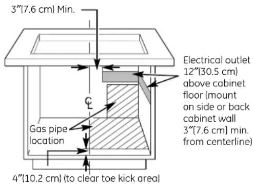
text_image
3"/[7.6 cm] Min. Electrical outlet 12"/[30.5 cm] above cabinet floor (mount on side or back cabinet wall 3"/[7.6 cm] min. from centerline) Gas pipe location 4"/[10.2 cm] (to clear toe kick area)4 PROVIDE ADEQUATE GAS SUPPLY
This cooktop is designed to operate on natural gas only at 5"(12.7 cm) of water column pressure or on LP gas at 10"(25.4 cm) of water column pressure. It is shipped from the factory set for natural gas. If you decide to use this cooktop with LP gas, conversion adjustments must be made by a service technician or other qualified person.
A pressure regulator is to be connected in series with the manifold of the cooktop and must remain in series with the supply line, regardless of whether natural or LP gas is being used.
For proper operation, the maximum inlet pressure to the regulator must be no more than 10"(25.4 cm) water column pressure for natural gas, or 14"(35.5 cm) water column pressure for LP gas. For checking the regulator, the inlet pressure must be at least 1"(2.5 cm) greater than the regulator output setting. If the regulator is set for 5"(12.7 cm) of water column pressure, the inlet pressure must be at least 6"(15.2 cm).
For ease of installation, and if local codes permit, the gas supply line into the cooktop should be 1/2" (13 mm) or 3/4" (19 mm) I.D. flexible metal appliance connector three (0.9 m) to five feet (1.5 m) in length.
5 PRESSURE TESTING
The maximum gas supply pressure for the regulator supplied on this appliance is 14" (35.5 cm) W.C. The test pressure for checking this regulator must be at least 6"(15.2 cm) W.C. for natural gas, and at least 11"(27.9 cm) W.C. for LP. It is shipped from the factory set for natural gas at 5"(12.7 cm) W.C.
This appliance and its individual shut-off valve must be disconnected from the gas supply piping system during any pressure testing of that system at test pressures in excess of 12 PSIG.
This appliance must be isolated from the gas supply piping system by closing its individual manual shut-off valve during any pressure testing of the gas supply piping system at test pressures equal to or less than 12 PSIG.
PREPARATION
6 PREPARE FOR DUCTWORK
NOTE: Ductwork MUST be vented outside. DO NOT vent into a wall, ceiling, crawlspace, attic or any concealed space.
Determine the best route for ductwork; it can be routed in a variety of ways depending on the kitchen layout.
IMPORTANT: The downdraft air discharge outlet for this unit is 3-1/4" x 10" rectangular. Plan ducting accordingly.
Typical duct arrangement countertop series.

text_image
Inside wall cabinetUp inside wall to roof or overhang
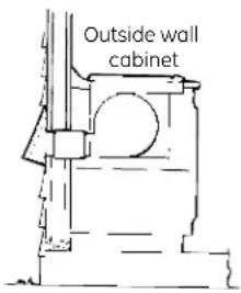
text_image
Outside wall cabinetDirectly to outside
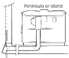
text_image
Peninsula or island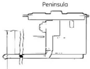
text_image
PeninsulaBetween floor joists Through cabinet toe space
Optional duct arrangement under concrete slab.
PVC duct should be used if installing under a poured concrete slab.
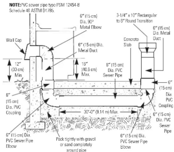
text_image
NOTE: PVC sewer pipe typo PSM 12454-B Schedule 40 ASTM D178b. Wall Cap 12" (30 cm) Min. 6" (15 cm) Dia. PVC Coupling 6" (15 cm) Dia. PVC Elbow 6" (15 cm) Dia. PVC Sewer Pipe 15" (40.5 cm) Max. 3'-1/4" x 10" Rectangular to 6" Round Transition Concrete Slab 6" (15 cm) Dia. Metal Duct 6" (15 cm) Dia. PVC Coupling 6" (15 cm) Dia. PVC Sewer Pipe 30'-0" (9.14 m) Max. 6" (15 cm) Dia. PVC Elbow Pack tightly with gravel or sand completely around pipe 6" (15 cm) Dia. PVC Sewer Pipe Elbow7 BLOWER TO DUCTWORK ALIGNMENT
In general, the use of flexible ducting is discouraged because it can cause severely restricted airflow. However, if the blower outlet and the floor or wall duct location do NOTalign well, then flexible METAL ducting can be used to adapt to an offset. Good alignment without use of flexible ducting is best.
NOTE:
Do not exceed the maximum recommended offset of 6".
Do not allow the flexible ducting to kink or collapse.
Do stretch the flexible ducting as much as possible to eliminate as much of the corrugation as possible.
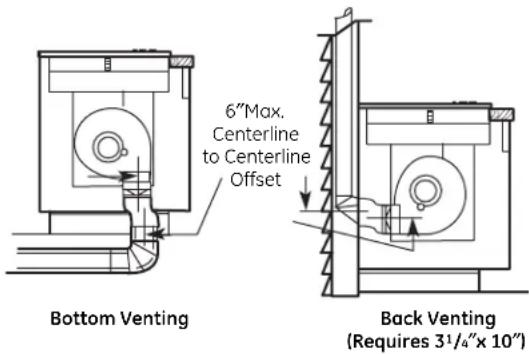
text_image
6"Max. Centerline to Centerline Offset Bottom Venting Back Venting (Requires 31/4"x 10")A 3 ^1/4 " x 10" rectangle to 6" round transition duct is available at your local building supply store.
NOTE: Illustrations are for planning purposes only.
PREPARATION
8 PLAN THE DUCT RUN
- Make a sketch of the total system. Identify the type of each fitting and the length of straight pipe. Refer to the examples on page 25.
- Enter your run into the Duct Length Chart on page 25. Elbows, wall caps and other fittings are shown in the chart with their equivalent straight duct length. Each fitting value must be added to the amount of straight duct length used to determine the overall straight duct equivalent length. Use the following examples as a guide.
- Using good quality ducting material, install per these instructions. A few minutes and pennies spent now will pay long term dividends for the life of the cooktop.
9 INSTALL THE DUCTWORK
- Ducting must conform to local code materials.
- IMPORTANT: Save for local electrical inspector's use.
- Use galvanized or aluminum duct in 6" round or 3 14 " x 10" size, or a combination of both.
NOTE: Local building codes must be followed in specifying approved type and schedule of ALL duct used. - Always use an appropriate roof or wall cap with damper.
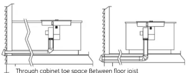
text_image
Through cabinet toe space Between floor joistDownward venting
- Laundry type wall caps should NEVER be used.
• Install ductwork, making male-female connections in the direction of airflow as shown. Secure all joints with sheet metal screws and duct tape to assure an airtight seal.
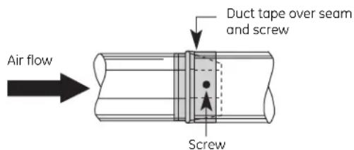
text_image
Air flow Duct tape over seam and screw Screw- Use the shortest and straightest duct run possible. For satisfactory performance, the duct run should not exceed 100 feet equivalent length.
- Use the Duct Length Chart on page 25 to find the equivalent length of the run.
- Ducting a cooktop is easy but critical for proper performance.
• After reading these instructions, plan the duct run.
• Install the duct hardware.
GENERAL CONSIDERATIONS:
- Use quality metal duct of at least 26-gauge galvanized or 24-gauge aluminum. Inferior quality pipe and fittings can cause up to twice the restriction shown and are a poor value. See the Prepare for DuctWork section of this manual for optional under-slab ducting. Local codes may require a heavier gauge material or restrict PVC.
- Distance between adjacent fittings (elbows, transitions, etc.) should be at least 18". The farther the better. Closer distance promotes turbulence which reduces airflow.
- The number of downstream elbows or transitions should be limited to three.
- Handmade crimps are likely to cause restrictions.
- If an alternate wall or roof cap is used, be certain duct size is not reduced and that there is a backdraft damper. It is best to use listed caps to be certain of proper performance.
- Thermal breaks: In areas of extreme cold weather, it may be necessary to provide a short length of nonmetallic duct as close to the wall as possible to prevent conduction along the metal duct.
- High altitude installations: It is advisable to reduce allowable duct run by 20%.
- Follow the duct calculation in this manual carefully for best performance and satisfaction.
DUCTWORK CALCULATIONS
| Calculate Total Equivalent Ductwork Length | |||
| Duct Pieces Length* x Used | Equivalent Number Equi ed = Length | valent | |
| 6" round straight 1 ft. x( ) †= | ft. | ||
| 31⁄4" x 10" straight 1 ft. x( ) †= | f | ||
| 6", 90° elbow | 15 ft. x ( ) = | ft. | |
| 6", 45° elbow | 9 ft. x ( ) = | ft. | |
| 24" max. Flexible Metal Offset Adapter | 34 ft. x ( ) = | ft. | |
| 31⁄4" x 10" 90° elbow | 16 ft. x ( ) = | ft. | |
| 31⁄4" x 10" 45° elbow | 5 ft. x ( ) = | ft. | |
| 31⁄4" x 10" 90° flat elbow | 18 ft. x ( ) = | ft. | |
| 6" round to 31⁄4" x 10" transition | 7 ft. x ( ) = | ft. | |
| Subtotal Column 1 = | ft. | ||
| *Equivalent lengths of duct pieces are based on actual tests and reflect requirements for good venting performance with any downdraft cooktop.† Measure and list feet of straight duct used. Count and list the quantity of all other duct pieces for the "Number Used" of each type.IMPORTANTFor maximum efficiency, use the shortest and straightest duct run possible, with as few fittings as possible.For satisfactory performance, the duct run should not exceed 100 feet equivalent length.Venting performance is improved by using larger diameter duct. | |||
| Duct Pieces Length* x | Equivalent Number Equivalent Used = Length | ||
| 6" round to 31⁄4" x 10" transition 90° elbow | 20 ft. x ( ) = | ft. | |
| 31⁄4" x 10" to 6" round transition | 5 ft. x ( ) = | ft. | |
| t. | 31⁄4" x 10" to 6" round transition 90° elbow | 12 ft. x ( ) = | ft. |
| 6" round wall cap with damper | 21 ft. x ( ) = | ft. | |
| 31⁄4" x 10" wall cap with damper | 27 ft. x ( ) = | ft. | |
| 6" round roof cap | 20 ft. x ( ) = | ft. | |
| 6" round roof vent | 24 ft. x ( ) = | ft. | |
| Subtotal Column 2 = | ft. | ||
| Subtotal Column 1 = | ft. | ||
| TOTAL DUCTWORK = | ft. | ||
| Should not exceed 100 feet. | |||
| DO NOT use flexible plastic ducting.Vent installation should not exceed 100 feet equivalent length. | |||
INSTALL THE COOKTOP
10 PREPARE THE COOKTOP
Remove the vent grille, vent filter, sealed burner module and the tape from the burner caps.
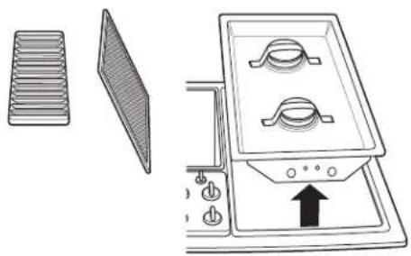
natural_image
Diagram of a kitchen appliance showing a grater, fan blade, and gas stove with an upward arrow (no text or symbols)Turn the cooktop over (upside down) and gently place it on the styrofoam packing.
Unscrew (loosen) the side hold-down screws.
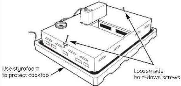
text_image
Use styrofoam to protect cooktop Loosen side hold-down screwsInstall the plenum to the cooktop using 4 screws. The motor opening on the box goes toward the left side of the unit (the side with the grease jar lid).
natural_image
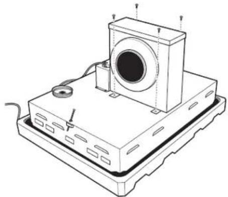
Technical line drawing of a mechanical device with a central circular component and base plate (no text or symbols)10 PREPARE THE COOKTOP (cont.)
Rotate the cooktop and plenum forward and carefully set it on its back edge on the styrofoam packing.
Install the blower assembly onto the plenum so that the blower exhaust is pointing down or back as needed. Push the bolts through the bolt holes in the plenum.
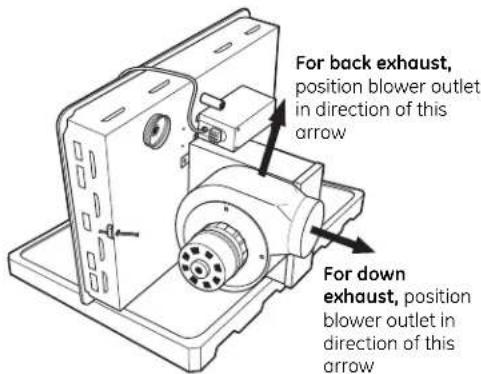
text_image
For back exhaust, position blower outlet in direction of this arrow For down exhaust, position blower outlet in direction of this arrowFrom the vent opening in the top of the cooktop, install the vent guard over the bolts. Use the 4 nuts to secure the blower assembly and vent guard to the inside of the plenum.
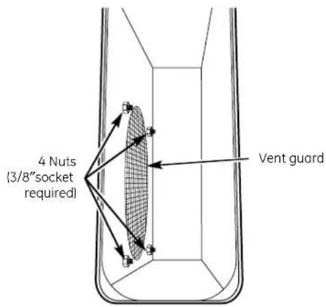
text_image
4 Nuts (3/8"socket required) Vent guardINSTALL THE COOKTOP
10 PREPARE THE COOKTOP (cont.)
Remove the blank 9-pin connector plug from the 9-pin receptacle on the bottom of the cooktop and discard. Connect the 9-pin plug on the blower assembly to the matching 9-pin receptacle on the bottom of the cooktop. Secure the connector cover to the cooktop using 3 screws, making sure the power cord comes out the U-shaped opening with the wires to the motor.
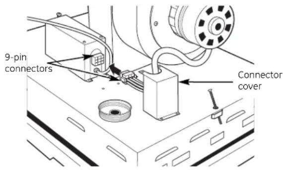
text_image
9-pin connectors Connector cover11 INSTALL THE PRESSURE REGULATOR AND CONNECT

text_image
Regulator Solid piping or flexible connector Union Solid piping or flexible connector Shut-off valve Pipe stub- For all connections, use a pipe sealant approved by local codes and resistant to the activity of L.P. gas.
• Install the pressure regulator in the gas line as close to the cooktop inlet as possible to allow clearance for ventilation ducting. - Make sure the arrow on the body of the regulator is pointing straight up and toward the cooktop. Any other position will affect the output pressure of the regulator. This arrow indicates correct gas flow direction.
• Install a manual gas line shut-off valve in an easily accessible location.
11 INSTALL THE PRESSURE REGULATOR AND CONNECT (cont.)
NOTE: Instead of using solid piping to connect to the pressure regulator, an approved flexible metal appliance connector may be used between the shut-off valve and the pressure regulator, if local codes permit.
Appropriate flare nuts and adapters are required at each end of the flexible connector.
Make sure all the knobs are in the off position. Hook up the gas line and check for leaks.
TEST FOR LEAKS
WARNING: DO NOT USE A FLAME TO CHECK
FOR GAS LEAKS! Do not use the cooktop until all connections have been leak tested.
Perform leak test per the following instructions:
- Purchase a liquid leak detector or prepare a soap solution of one part water, one part liquid detergent.
- When all connections have been made, make sure all cooktop controls are turned to OFF and turn the gas supply valve to ON.
- Apply the liquid leak detector or the soap solution around all connections from the shut-off valve to the cooktop.
- A leak is identified by a flow of bubbles from the area of the leak.
- If a leak is detected, turn the gas supply off. Tighten the fitting. Turn the gas on and test again. If the leak persists, turn the gas supply off and contact your dealer for assistance. Do not attempt to operate the cooktop if a leak is present.
IMPORTANT: Disconnect the cooktop and the individual shut-off valve from the gas supply piping system during any pressure testing of that system at test pressures greater than 1/2 psig. Isolate the cooktop from the gas supply piping system by closing the individual manual shut-off valve to the cooktop during any pressure testing of the gas supply piping system at test pressures equal to or less than 1/2 psig.
INSTALL THE COOKTOP
12 INSTALL THE COOKTOP
Lower the cooktop into the countertop opening, guiding it into position.
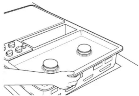
natural_image
Line drawing of a hand holding a car intake tray with three circular buttons (no text or symbols)13 SECURE THE COOKTOP
Tighten the tie-down bolts to secure the cooktop to the counter. For countertops less than 1"thick, securely attach filler blocks of wood to the bottom of the countertop where the tie-down bolts will be tightened.
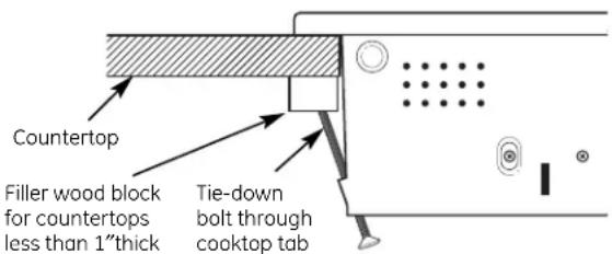
text_image
Countertop Filler wood block for countertops less than 1"thick Tie-down bolt through cooktop tab14 OPTIONAL: ATTACH A BLOWER TRANSITION DUCT
If using 6"round standard ductwork, attach a blower transition duct. This 3 14 "×10"rectangle to 6"round transition duct is available at your local building supply store.
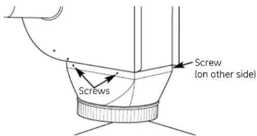
text_image
Screws Screw (on other side)Install the transition duct to the blower outlet. Secure all joints with duct tape to assure an airtight seal.
15 CONNECT THE DUCTWORK
Connect the ductwork prepared earlier to the blower transition duct.
16 ELECTRICAL CONNECTION
Electrical requirements:
120-volt, 60-Hertz, individual, properly grounded branch circuit protected by a 15-amp circuit breaker or time-delay fuse.
GROUNDING
IMPORTANT: (Please read carefully.) FOR PERSONAL SAFETY, THIS APPLIANCE MUST BE PROPERLY GROUNDED.
The power cord of this appliance is equipped with a three-prong (grounding) plug which mates with a standard three-prong grounding wall receptacle to minimize the possibility of electric shock hazard from this appliance. The customer should have the wall receptacle and circuit checked by a qualified electrician to make sure the receptacle is properly grounded and has correct polarity.
Where a standard two-prong wall receptacle is encountered, it is the personal responsibility and obligation of the customer to have it replaced with a properly grounded three-prong wall receptacle in accordance with the National Electrical Code.
Do Not, Under Any Circumstances, Cut Or Remove The Third (Ground) Prong From The Power Cord.
Do not use an extension cord with this appliance. Plug the power cord into an approved wall outlet.
FINAL ASSEMBLY
17 ASSEMBLE THE COOKTOP
Install the sealed burner module, caps and grate on the right side of the unit. See page 10 for correct installation.

natural_image
Line drawing of a gas stove with two burners and a downward arrow indicating cooling (no text or symbols)Install the optional sealed burner module or the grill/griddle burner on the left side of the unit.
If the grill/griddle burner was installed, place the grill grate or griddle cover over it as desired.
NOTE: The grill and griddle can be installed on the left side only.

natural_image
Two 3D rectangular shapes with horizontal lines, one plain and one striped (no text or symbols)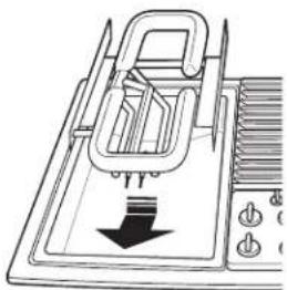
natural_image
Diagram of a mechanical device with a downward arrow indicating force or direction (no text or symbols present)Check for proper ignition:
Push in one control knob and turn to LITE position.
The igniter will spark and the burner will light; igniter will cease sparking when the burner is lit.
First test may require some time while air is flushed out of the gas line.
Turn knob to OFF.
Repeat the procedure for each burner.
Adjust the air shutters (see LP Conversion Instructions).
Adjust the low flame setting (see LP Conversion Instructions).
18 INSTALL GREASE JAR, DOWNDRAFT FILTER AND VENT GRILLE
Screw the grease jar into the grease jar holder on the bottom of the cooktop.
natural_image
Hand holding a small object above a rectangular block (no text or symbols visible)Do not operate the vent without the filter in place.
Place the filter through the vent opening.
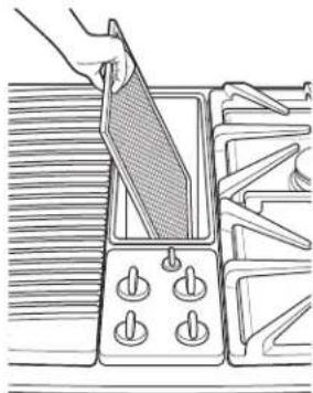
natural_image
Illustration of a hand holding a triangular object over a grid-patterned device (no text or symbols)Make sure it rests, at an angle, on the supports in the vent opening. Latch it in place.
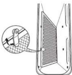
natural_image
Diagram showing a device interacting with a mesh panel, with an inset magnified view of the component (no text or symbols)Place the vent grille onto the downdraft opening so that the open part of the grille is toward the rear of the unit.

text_image
GrilleCHECK OPERATION OF DOWNDRAFT
Turn the vent fan speed control to HI, MED and LO to make sure all speeds operate correctly.
LP Conversion Gas Cooktop Instructions
Questions? Call 800.GE.CARES (800.432.2737) or Visit our Website at: ge.com
BEFORE YOU BEGIN
Read these instructions completely and carefully.
- IMPORTANT – Save these instructions for local inspector's use.
- IMPORTANT – Observe all governing codes and ordinances.
- Note to Installer – Be sure to leave these instructions with the Consumer.
- Note to Consumer – Keep these instructions for future reference.
- This cooktop is factory set for natural gas operation. Conversion to LP operation should be performed by a qualified technician or installer. Keep these instructions for future reference. When converting to LP, save the original parts for possible future use.
- Product failure due to improper installation is not covered under the GE Appliance Warranty.
FOR YOUR SAFETY:
WARNING – If you are using LP (bottled) gas, all adjustments described in the following steps must be made before attempting burner adjustments or use of the cooktop.
WARNING - This conversion kit shall be installed by a qualified service agency in accordance with the manufacturer's instructions and all applicable codes and requirements of the authority having jurisdiction. If the information in these instructions is not followed exactly, a fire, explosion or production of carbon monoxide may result, causing property damage, personal injury or loss of life. The qualified service agency is responsible for the proper installation of this kit. The installation is not proper and complete until the operation of the converted appliance is checked as specified in the manufacturer's instructions supplied with the kit.
TOOLS YOU WILL NEED
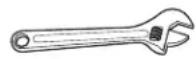
Adjustable wrench

Small, thin-blade flat screwdriver with approximately 1/8" blade width is needed to access the calibration screw.
PARTS INCLUDED
| PART QUANTITY | ||
 | Brass orifices 4 | |
 | Stick-on conversion label 1 | |
GAS SUPPLY
- With the installation of this conversion kit, the cooktop should operate on LP gas at 10" of water column pressure.
- The pressure regulator must be connected in series with the manifold of the cooktop and must remain in series with the supply line. For proper operation, the maximum inlet pressure to the regulator must be no more than 14"water column pressure for LP gas.
- When checking the regulator, the inlet pressure must be at least 1" greater than the regulator output setting. If the regulator is set for 10" of water column pressure, the inlet pressure must be at least 11."
IMPORTANT - Disconnect the cooktop and the individual shut-off valve from the gas supply piping system during any pressure testing of that system at test pressures greater than 1/2 psig. Isolate the cooktop from the gas supply piping system by closing the individual manual shut-off valve to the cooktop during any pressure testing of the gas supply piping system at test pressures equal to or greater than 1/2 psig.
TURN OFF GAS AND ELECTRIC SUPPLY
BEFORE YOU BEGIN, TURN OFF THE GAS SUPPLY AT THE SHUT-OFF VALVE. DISCONNECT THE ELECTRICAL SUPPLY FROM THE COOKTOP.

text_image
Shut-off valve Electrical supply1 CONVERT THE PRESSURE REGULATOR
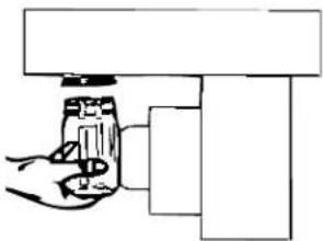
A Locate the pressure regulator under the front of the cooktop.

natural_image
Pure technical line drawing of a mechanical or electrical component assembly without any text, numbers, or symbolsB Remove the nut from the pressure regulator with an adjustable wrench.
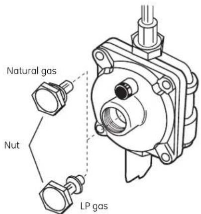
text_image
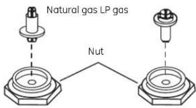
Natural gas Nut LP gasC Remove the plastic pin from the inside of the nut, turn the pin 180° and snap the pin back into the nut.
text_image
Natural gas LP gas NutD Re-install the nut onto the regulator.
E Apply the LP Conversion label next to the Rating Plate.
2 CONVERT SURFACE BURNERS

text_image
Turn clockwise to tighten OrificeTurn counterclockwise to remove
A Remove all grates and burner modules.
B With an adjustable wrench or an open end wrench, remove the brass orifices.
C Find the inscribed LP orifices in the holder in the front of the electric cover beneath the cooktop.
D Install the inscribed LP orifices in place of the natural gas orifices.
E Replace the burner modules and grates.
F Keep all the spuds with your cooktop so you have them if you move or get a different gas hook-up.
LP (Propane) Gas 10"W.C.P.
Burner Output Rating in BTU/HR
Location BTUs Orifice Size Engraving
| Left Rear (LR) 9,100 .0354 LP |
| Left Front (LF) 9,100 .0354 LP |
| Right Rear (RR) 9,100 .0354 LP |
| Right Front (RF) 9,100 .0354 LP |
3 ADJUST GRILL BURNER AIR SHUTTER
text_image
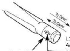
To Open To Close Lo A TAir shutter
Loosen screw
Adjust air shutter opening
Tighten screw
The air shutters for the grill burner may need to be adjusted to get better flame appearance and ignition. The air shutters for the grill burner are located on the bottom of the grill burner. To access the air shutters, remove the grill grate, and then the grill burner. Loosen the screw and slide the air shutter backward or forward to increase or decrease the size of the air opening. Re-tighten the screw.
4 CHECK IGNITION
A Connect electrical supply cord.
B Turn on the gas; check for leaks using a liquid leak detector at all joints in the system.
WARNING: DO NOT USE A FLAME TO CHECK FOR GAS LEAKS.
Push in one control knob and turn to the LITE position. The igniter will spark and the burner will light. The first test may require some time while air is flushed out of the gas line. After ignition, turn the control knob to the HI position and wait until the f
Check to determine if your burner flames are normal. If burner flames look like A, turn off the burner and make sure all parts are assembled correctly. Reassemble and check. Normal burner flames should look like B or C, depending on the type of gas you use. With LP gas, some yellow tipping on outer cones is normal.

A-Yellow flames
Not normal;
check
alignments
B-Yellow tips
Normal for
LP gas
C-Soft blue flames
Normal for
natural gas
D Turn the knob to OFF.
E Repeat the procedure for each burner.
5 ADJUST THE LOW FLAME (SIMMER) SETTING
The top burner valves have low flame/simmer adjustment screws accessible through the valve switches. A flashlight may be needed to locate the screw. A small, thin-blade screwdriver (approximately 1/8"blade width) is needed to access the screw.
A Light two other burners and set the knobs to a medium to high setting.
B Light the burner to be adjusted and turn the knob to LOW.
C To make adjustment, remove the control knobs. Insert a screwdriver through the access hole in the valve switch. Engage the adjustment screw in the valve.
If the flames were too small or fluttered, open the valve more than the original setting.
If the flames are too large, close the valve more than the original setting.

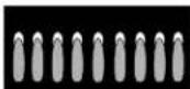
natural_image
Line drawing of a hand using a pipette to apply liquid onto small circular objects on a tray (no text or symbols)D Make the adjustment by slowly turning the screw until the flame appearance is correct. For the left side, install the grill burner for the adjustment. The left side cannot be turned down as low as the right side if the grill burner is to be used.
Adjust the low flame setting using the valve bypass screw as follows:
Low setting adjustments must be made with two other burners in operation on a medium setting. This prevents the low flame from being set too low, resulting in the flame being extinguished when other burners are turned on.
E Testing Flame Stability:
Test 1: Turn the knob from HI to LOW quickly.
If the LOW flame goes out, increase the flame size and test again.
Test 2: With the burner on the LOW setting, open and close the cabinet door under the cooktop. If the flame is extinguished by the air currents created by the door movement, increase the flame height and test again.
Test 3: With the burner on the LOW setting, turn the downdraft vent fan to the HI position. If the flame is extinguished by the air currents created by the downdraft vent fan, increase the flame size and test again.
⑤ ADJUST THE LOW FLAME (SIMMER) SETTING(cont.)
F Flame Recheck:
Repeat the adjustment for each burner. After the adjustment is made, turn all burners off. Ignite each burner individually. Observe the flame at the HI position. Rotate the valve to the LOW position and be sure that the flame size decreases as the valve is rotated counterclockwise.
⑥ CONVERTING BACK TO NATURAL GAS
To convert the cooktop back to natural gas, reverse the steps taken to convert to LP.
| Natural Gas 5”WC.P. | |
| Burner Output Rating in BTU/HR | |
| Location BTUs Orifice Size Engraving | |
| Left Rear (LR) 10,000 .0550 NAT | |
| Left Front (LF) | 10,000 .0550 NAT |
| Right Rear (RR) | 10,000 .0550 NAT |
| Right Front (RF) | 10,000 .0550 NAT |
Once the conversion is complete and checked OK, fill out the LP sticker and include your name, organization and date conversion was made. Apply the sticker near the cooktop gas inlet opening to alert others in the future that this appliance has been converted to LP gas. If converting back to natural gas from LP, please remove the sticker so others know the appliance is set to use natural gas.
NOTE: For operation at elevations above 5000 ft. (1500 m), equipment ratings shall be reduced at a rate of 2% for each 1000 ft. (300 m) above sea level before selecting appropriately sized equipment, i.e.: Use smaller orifices.
Before you call for service...

Troubleshooting Tips
Save time and money! Review the charts on the following
pages first and you may not need to call for service.
| Problem Possible Causes What To Do | |||
| Burners do not light | Plug on cooktop is not completely inserted in the grounded outlet. | Make sure electrical plug is plugged into a live, properly electrical outlet. | |
| Gas supply not connected or turned on. | See the Installation Instructions section. | ||
| A fuse in your home may be blown or the circuit breaker tripped. | Replace the fuse or reset the circuit breaker. | ||
| Igniter orifice in burner body may be clogged. | Remove the obstruction. | ||
| Burner parts not replaced correctly. | See Sealed Burner Modules in the Care and cleaning of the cooktop section. | ||
| Slits in the burner head may be clogged. | Use a small sewing needle or paper clip to unplug. | ||
| Burners have yellow or yellow-tipped flames or flames lift off the port | The combustion quality of burner flames needs to be determined visually. |  |   |
| A-Yellow flamesCall for service | B-Yellow tips on outer conesNormal for LP gas C-Soft blue flamesNormal for natural gas | ||
| If burner flame looks like A, call for service. Normal burner flames should look like B or C, depending on the type of gas. | |||
| NOTE: The grill burner will show orange flames from grease drippings. | |||
| Burner parts not replaced correctly. | See Care and cleaning of the cooktop section. | ||
| Burner flames make excessive noise | Burner has not been used recently. | A "cold" burner ignited in the HI setting may have some flame "roar" or "lifting." This should dissipate after 4 to 5 minutes. | |
| Burner flames pulled toward vent grille | Vent fan set at HI speed. | This is normal. If cooking performance is affected, change fan to a lower fan speed setting. | |
| Flames too high or too low at the LOW setting | Adjust the low flame setting. 1 Light the top burners and continue turning all ofNOTE: The right side LOW flames should be smaller 2 Remove all 4 knobs. than the left side, because 3 With a small flat-blade the left side can accommodate screwdriver, turn the valve the grill burner. Do not set screws clockwise to adjust the left side unless you decrease flame size, do not have a grill module. counterclockwise to increase flame size. Adjust until the flame is about the same height as the top of the burner.4 Replace the knobs. | Clockwise to reduce flame size | Counterclockwise to increase size |
| Sparking sound persists after burner is turned off | Be sure the knob is in the OFF position. | Remove knob by pulling it straight off the stem and check the bottom of the knob for any buildup of soil. | |
| Occasional sparking sound | Changing blower speed. | This is a typical electrical switching noise.This is normal. | |
| Burner flames very large or yellow | Burner parts not replaced correctly. | See Care and cleaning of the cooktop section. | |
| Flames are uneven | Burner ports may be clogged. | See the Care and cleaning section. | |
| Flame setting may need to be adjusted. | See Flames too high or too low at the LOW setting in this Troubleshooting Tips section. | ||
| Control knobs will not turn | Controls improperly set. | To turn from the OFF position, push the knob in and then turn. The knob can only be turned in a counterclockwise direction. When the knob is at any other position, it can be turned in either direction without being pushed in. | |
| Fan does not work | Cord improperly connected or power turned off. | Check connections. Turn on power at the fuse box. | |
| Fan comes on automatically | Grill or griddle is being used. | This is normal. The fan will automatically turn on and operate continuously while the grill burner module is in use. | |
| Poor venting | Clogged filter. | Clean filter per instructions. | |
| House too airtight. | Open a window slightly to provide fresh air source. | ||
| Wall cap obstructed. | Remove blockage from exterior wall cap. | ||
| Wall cap damper door stuck. | Check exterior wall cap damper door for free movement or obstruction. | ||
| Duct length exceeds recommended 100 equivalent foot maximum. | Reduce number of elbows to simplify duct run. | ||
| Areas of discoloration on the cooktop | Food spillovers not cleaned before next use. | See the Care and cleaning section. | |
| Water won't boil | Cover pan with a lid.Turn the downdraft fan OFF until the water begins to boil. | ||
| Consumer Support | Care and Cleaning Tro | Operating Instructions | Safety Instructions |
Notes.
GE Service Protection Plus™
GE, a name recognized worldwide for quality and dependability, offers you Service Protection Plus™—comprehensive protection on all your appliances—No Matter What Brand!
Benefits Include:
- Backed by GE
- All brands covered
- Unlimited service calls
- All parts and labor costs included
- No out-of-pocket expenses
- No hidden deductibles
• One 800 number to call
We'll Cover Any Appliance. Anywhere. Anytime.\*
You will be completely satisfied with our service protection or you may request your money back on the remaining value of your contract. No questions asked. It's that simple.
Protect your refrigerator, dishwasher, washer and dryer, range, TV, VCR and much more—any brand! Plus there's no extra charge for emergency service and low monthly financing is available. Even icemaker coverage and food spoilage protection is offered. You can rest easy, knowing that all your valuable household products are protected against expensive repairs.
Place your confidence in GE and call us in the U.S. toll-free at 800.626.2224 for more information.
*All brands covered, up to 20 years old, in the continental U.S.

Cut here
Please place in envelope and mail to:
General Electric Company
Warranty Registration Department
P.O. Box 32150
Louisville, KY 40232-2150
Consumer Product Ownership Registration
Dear Customer:
Thank you for purchasing our product and thank you for placing your confidence in us.
We are proud to have you as a customer!
Follow these three steps to protect your new appliance investment:

Complete and mail your Consumer Product Ownership Registration today. Have the peace of mind of knowing we can contact you in the unlikely event of a safety modification.

text_image
2After mailing the registration below, store this document in a safe place. It contains information you will need should you require service. Our service number is 800.GE.CARES (800.432.2737).

text_image
3Read your Owner's Manual carefully. It will help you operate your new appliance properly.
Model Number Serial Number

natural_image
Two identical horizontal lines with tick marks, no text or symbols presentImportant: If you did not get a registration card with your product, detach and return the form below to ensure that your product is registered, or register online at ge.com.

Cut here
Consumer Product Ownership Registration

Model Number Serial Number

natural_image
Two identical horizontal lines with tick marks, no text or symbols present
text_image
First Name Mr. □ Ms. □ Mrs. □ Miss □ Last Name Street Address Apt. # E-mail Address* City State Zip Code Date Placed in Use Month Day Year Phone Number -
GE Consumer & Industrial
Appliances
General Electric Company
Louisville, KY 40225
ge.com
* Please provide your e-mail address to receive, via e-mail, discounts, special offers and other important communications from GE Appliances (GEA).
□ Check here if you do not want to receive communications from GEA's carefully selected partners.
FAILURE TO COMPLETE AND RETURN THIS CARD DOES NOT DIMINISH YOUR WARRANTY RIGHTS.
For information about GEA's privacy and data usage policy, go to ge.com and click on
"Privacy Policy" or call 800.626.2224.
GE Gas Cooktop Warranty.
All warranty service provided by our Factory Service Centers, or an authorized Customer Care® technician. To schedule service, on-line, visit us at ge.com, or call 800.GE.CARES (800.432.2737). Please have serial number and model number available when calling for service.
Staple your receipt here. Proof of the original purchase date is needed to obtain service under the warranty.
For The Period Of: GE Will Replace:
One Year
From the date of the
Any part of the cooktop which fails due to a defect in materials or workmanship. During this limited one-year warranty, GE will also provide, free of charge, all labor and related service
original purchase to replace the defective part.
What GE Will Not Cover:
■ Service trips to your home to teach you how to use the product.
■Improper installation, delivery or maintenance.
Failure of the product if it is abused, misused, or used for other than the intended purpose or used commercially.
■ Replacement of house fuses or resetting of circuit breakers.
■ Damage to the product caused by accident, fire, floods or acts of God.
■Incidental or consequential damage caused by possible defects with this appliance.
■ Damage caused after delivery.
■ Product not accessible to provide required service.
EXCLUSION OF IMPLIED WARRANTIES—Your sole and exclusive remedy is product repair as provided in this Limited Warranty. Any implied warranties, including the implied warranties of merchantability or fitness for a particular purpose, are limited to one year or the shortest period allowed by law.
This warranty is extended to the original purchaser and any succeeding owner for products purchased for home use within the USA. If the product is located in an area where service by a GE Authorized Servicer is not available, you may be responsible for a trip charge or you may be required to bring the product to an Authorized GE Service Location for service. In Alaska, the warranty excludes the cost of shipping or service calls to your home.
Some states do not allow the exclusion or limitation of incidental or consequential damages. This warranty gives you specific legal rights, and you may also have other rights which vary from state to state. To know what your legal rights are, consult your local or state consumer affairs office or your state's Attorney General.

GE Appliances Website
ge.com
Have a question or need assistance with your appliance? Try the GE Appliances Website any day of the year! For greater convenience and faster service, you can now download Owner's Manuals, order parts or even schedule service on-line.
Schedule Service ge.com
Expert GE repair service is only one step away from your door. Get on-line and schedule your service at your convenience any day of the year! Or call 800.GE.CARES (800.432.2737) during normal business hours.
Real Life Design Studio ge.com
GE supports the Universal Design concept—products, services and environments that can be used by people of all ages, sizes and capabilities. We recognize the need to design for a wide range of physical and mental abilities and impairments. For details of GE's Universal Design applications, including kitchen design ideas for people with disabilities, check out our Website today. For the hearing impaired, please call 800.TDD.GEAC (800.833.4322).
Extended Warranties ge.com
Purchase a GE extended warranty and learn about special discounts that are available while your warranty is still in effect. You can purchase it on-line anytime, or call 800.626.2224 during normal business hours. GE Consumer Home Services will still be there after your warranty expires.

Parts and Accessories ge.com
Individuals qualified to service their own appliances can have parts or accessories sent directly to their homes (VISA, MasterCard and Discover cards are accepted). Order on-line today, 24 hours every day or by phone at 800.626.2002 during normal business hours.
Instructions contained in this manual cover procedures to be performed by any user. Other servicing generally should be referred to qualified service personnel. Caution must be exercised, since improper servicing may cause unsafe operation.

Contact Us ge.com
If you are not satisfied with the service you receive from GE, contact us on our Website with all the details including your phone number, or write to: General Manager, Customer Relations
GE Appliances, Appliance Park Louisville, KY 40225
Register Your Appliance ge.com
Register your new appliance on-line—at your convenience! Timely product registration will allow for enhanced communication and prompt service under the terms of your warranty, should the need arise. You may also mail in the pre-printed registration card included in the packing material.
text_image
Technical diagram of a heat exchanger or fan with numbered components labeled 1 through 7natural_image
Simple 3D illustration of a rectangular block with horizontal striped texture (no text or symbols)Asador Modelo JXGG90L
natural_image
Technical line drawing of a four-tiered gas stove or vent (no text or symbols)natural_image
Simple line drawing of a tray with six circular and rectangular cutouts, no text or symbols present.Plancha Modelo JXGL90L
natural_image
Illustration of hands pressing down on a mechanical component with a downward arrow (no text or symbols)text_image
OFF LO MED HInatural_image
Line drawing of a gas stove with cooling fans and a down arrow indicating heating (no text or symbols)natural_image
Diagram of a mechanical device with a downward arrow indicating motion or force, no text or symbols presentMódulo de asador
natural_image
Diagram of a refrigerator with ventilation slots and control buttons (no text or symbols)natural_image
Simple line drawing of a hand using a tool to interact with a bracket (no text or symbols)natural_image
Line drawing of a hand using a tool to clean or install a stove (no text or symbols present)Quemador del asador
natural_image
Hand holding a small object over a striped surface (no text or symbols)Parrilla del asador
natural_image
Illustration of a hand using a tool to cut a component into a rack (no text or symbols visible)natural_image
Diagram of a door panel with a magnified inset showing a hand holding a tool, no text or symbols present.natural_image
Technical line drawing of a gas stove or gas stove unit with four panes and a central vent (no text or symbols)Ignitores Electrodos
text_image
Peninsulanatural_image
Architectural cross-section diagram of a structural assembly (no text or labels)
natural_image
Technical line drawing of a mechanical assembly with no visible text or symbolsnatural_image
Diagram showing a kitchen appliance with a gridded lid, a side panel, and a gas stove with a rising arrow (no text or symbols)natural_image
Technical line drawing of a mechanical device with a circular component and base plate (no text or symbols)10 PREPARE LA ESTUFA (cont.)
natural_image
Line drawing of a hand holding a tray with two circular buttons (no text or symbols)13 ASEGURE LA ESTUFA
natural_image
Line drawing of a gas stove with cooling fans and a down arrow indicating airflow (no text or symbols)natural_image
Two rectangular objects: a flat rectangular plate and a textured rectangular block with horizontal lines (no text or symbols)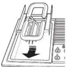
natural_image
Diagram of a mechanical device with a downward arrow indicating force or direction (no text or symbols present)natural_image
Illustration of a hand using a tool to cut or remove a component, with no visible text or symbols.natural_image
Diagram of a person inside a container with a mesh panel, showing a magnified inset (no text or symbols)natural_image
Technical line drawing of a device with connectors and cables (no text or symbols)text_image
Gas natural Tuerca Gas LPtext_image
Gas natural Gas LP Tuercanatural_image
Illustration of a hand using a pipette to apply liquid onto small circular objects on a tray (no text or symbols)Garante: General Electric Company. Louisville, KY 40225

General Manager, Customer Relations
GE Appliances, Appliance Park
Louisville, KY 40225