ZV42ISHSS - Range hood GE - Free user manual and instructions
Find the device manual for free ZV42ISHSS GE in PDF.

User questions about ZV42ISHSS GE
0 question about this device. Answer the ones you know or ask your own.
Ask a new question about this device
Download the instructions for your Range hood in PDF format for free! Find your manual ZV42ISHSS - GE and take your electronic device back in hand. On this page are published all the documents necessary for the use of your device. ZV42ISHSS by GE.
USER MANUAL ZV42ISHSS GE
Installation Instructions
If you have questions, call 800.GE.CARES or visit our website at: monogram.com
Island Vent Hoods
Models:
ZV421
ZV541
READ AND SAVE THESE INSTRUCTIONS
BEFORE YOU BEGIN
Read these instructions completely and carefully.
- IMPORTANT – Save these instructions for local inspector's use.
- IMPORTANT – Observe all governing codes and ordinances.
- Note to Installer — Be sure to leave these instructions with the Consumer.
- Note to Consumer — Keep these instructions with your Owner's Manual for future reference.
- Skill Level — Installation of this appliance requires basic mechanical and electrical skills.
• Completion Time – 1 to 3 Hours. - Proper installation is the responsibility of the installer. Product failure due to improper installation is not covered under the warranty.
For Monogram local service in your area, call 1.800.444.1845. For Monogram service in Canada, call 1.800.561.3344. For Monogram Parts and Accessories, call 1.800.626.2002.
CAUTION:
Due to the weight and size of these vent hoods and to reduce the risk of personal injury or damage to the product, THREE PEOPLE ARE REQUIRED FOR PROPER INSTALLATION.
WARNING:
To reduce the risk of fire or electrical shock, do not use this range hood with any external solid-state speed control device. Any such alteration from original factory wiring could result in damage to the unit and/or create an electrical safety hazard.
TO REDUCE THE RISK OF FIRE, USE ONLY METAL DUCTWORK.
WARNING: TO REDUCE THE RISK OF FIRE, ELECTRICAL SHOCK OR INJURY TO PERSONS, OBSERVE THE FOLLOWING:
A. Use this unit only in the manner intended by the manufacturer. If you have any questions, contact the manufacturer.
B. Before servicing or cleaning the unit, switch the power off at the service panel and lock the service disconnecting means to prevent the power from being switched on accidentally. When the service disconnecting means cannot be locked, securely fasten a prominent warning device, such as a tag, to the service panel.
CAUTION: FOR GENERAL VENTILATING USE ONLY. DO NOT USE TO EXHAUST HAZARDOUS MATERIALS, EXPLOSIVE MATERIALS OR VAPORS.
WARNING: TO REDUCE THE RISK OF FIRE, ELECTRICAL SHOCK OR INJURY TO PERSONS, OBSERVE THE FOLLOWING:
- Installation work and electrical wiring must be done by qualified person(s) in accordance with all applicable codes and standards, including fire-rated construction.
-
Sufficient air is needed for proper combustion and exhausting of gases through the flue (chimney) of fuel burning equipment to prevent back-drafting. Follow the heating equipment manufacturer's guidelines and safety standards, such as those published by the National Fire Protection Association (NFPA), the American Society for Heating, Refrigeration and Air Conditioning Engineers (ASHRAE) and the local code authorities. When applicable, install any makeup (replacement) air system in accordance with local building code requirements. Visit GEAppliances.com for available makeup air solutions.
-
When cutting or drilling into walls or ceilings, do not damage electrical wiring and other hidden utilities.
- Ducted systems must always be vented to the outdoors.
- Local codes vary. Installation of electrical connections and grounding must comply with applicable codes. In the absence of local codes, the vent should be installed in accordance with National Electrical Code ANSI/NFPA 70-1990 or latest edition.
CAUTION: To reduce risk of fire and to properly exhaust air, be sure to duct air outside—do not vent exhaust air into spaces within walls or ceilings or into attics, crawl spaces or garages.
LISEZ ET CONSERVEZ CES INSTRUCTIONS
AVANT DE COMMENCER
Product Dimensions ....4
Duct Cover Accessories ....5
Product Clearances ....5
Advance Planning
Ductwork Planning 6
Ceiling Framing for Support 6
Accessory Frames and Duct Covers ....6
Mounting the hood without a support frame ....6
Power Supply 6
Installation Height 7
Duct Fittings 8
Installation Preparation
Tools and Materials Required 9
Remove the Packaging 9
Parts, Hardware, Accessory Packages 10
Installation Instructions
Step 1, Construct Ceiling Support .... 11–13
Step 2, Mount Template 14
Step 3, Size and Install Ductwork 14
Step 4, Install Support Frame and Duct Covers ..... 15
Step 5, Install Duct Transition and Damper 16
Step 6, Install Hood to Support 16
Step 7, Connect Duct 16
Step 8, Connect Electrical 17
Step 9, Install the Motor 17
Step 10, Slide Duct Cover Down 18
Step 11, Install Filters 18
Step 12, Install Rods 18
Step 13, Install Supplied Duct Cover, Top Cover ..... 19
Step 14, Finalize Installation 19
Step 15, Installation Checklist .... 19
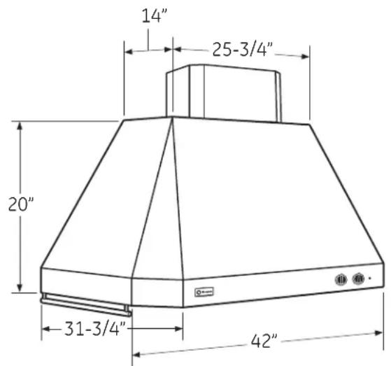
42" HOOD DIMENSIONS
Model ZV421
text_image
14" 25-3/4" 20" 31-3/4" 42"54" HOOD DIMENSIONS
Model ZV541
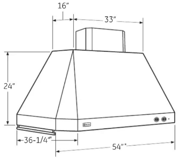
text_image
16" 33" 24" 36-1/4" 54"Supplied duct covers dimensions: 16"W x 12"D x 9"H Supplied duct covers dimensions: 20-1/4"W x 12"D x 5"H
These vent hoods are supplied with a support frame and decorative duct cover for ceiling heights of 7'11" to 8'5". The hood installation height is determined by the ceiling height. Accessories are available to reach ceiling heights from 8'6" to 10'4".
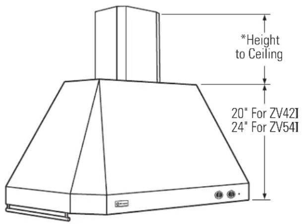
DUCT COVER ACCESSORIES
text_image
*Height to Ceiling 20" For ZV42I 24" For ZV54IZV421
* 9" for ceiling heights 7'11" to 8'5" using the supplied support frame and duct cover.
Order ZX42DC10 for ceiling heights of 8"6" to 10'4".
ZV54I
* 5" for ceiling heights 7'11" to 8'5" using the supplied support frame and duct cover.
Order ZX54DC10 for ceiling heights of 8"6" to 10'4".
These accessories include telescoping support frames and decorative covers. Order the accessory for your model at the same time as the vent hood and have on site before installation begins.
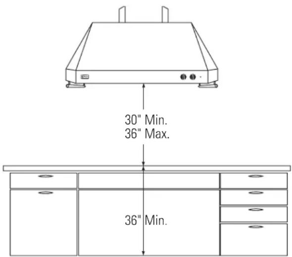
PRODUCT CLEARANCES
text_image
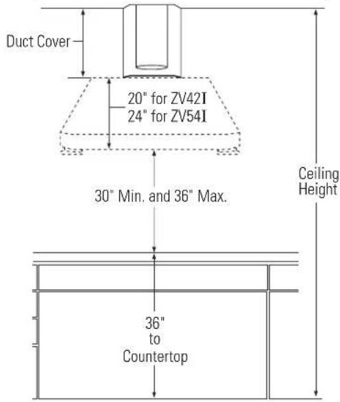
30" Min. 36" Max. 36" Min.These vent hoods must be installed 30" min. to 36" max. above the cooking surface. Exact installation height is determined by ceiling height. The cooking surface should be at least 36" above the floor.
IMPORTANT: Clearances may vary due to type of cooking product and local codes. Check with local inspectors to be sure standard is applicable.
- When installing these Island Hoods above a Monogram Professional Range or Cooktop, installation clearance must be at least 30".
ADVANCE PLANNING
Ductwork Planning
- These vent hoods are equipped for 10" round ductwork.
- Determine the exact location of the vent hood.
- Plan the route for venting exhaust to the outdoors.
- Use the shortest and straightest duct route possible. For satisfactory performance, duct run should not exceed 150 ft. equivalent length for any duct configurations.
- Refer to "Duct Fittings" chart to compute the maximum permissible length for duct runs to the outdoors.
- Use rigid metal ductwork only.
- Install a roof cap with damper at the exterior opening. Order the cap and any transitions needed in advance.
- When applicable, install any makeup (replacement) air system in accordance with local building code requirements. Visit GEAppliances.com for available makeup air solutions.
Ceiling Framing for Adequate Support
- These vent hoods are heavy. Adequate structural support must be provided. The ceiling structure must be capable of supporting the weight of the hood and any inadvertent user contact loads (approximately 300 pounds). The hood support frame will be supported by 2 × 4 cross framing.
Accessory Frames and Duct Covers
- All models are shipped with a support frame and duct covers for ceilings heights of 7'11" to 8'5".
- Optional accessories include telescoping support frames and duct covers to reach 8'6" and up to 10'4" ceiling heights.
- Optional accessories must be ordered with the hood and be on site before final framing and wall finishing.
Mounting the hood without a support frame
The distance between the cooking surface and the bottom of the hood must be 30" to 36". In situations where the ceiling is low, the hoods may be secured directly to the ceiling without the supplied frame. Use the bottom of the supplied support frame as a template to locate the mounting holes in the top of the hood. Use shims on the ceiling joists or cross framing in the mounting hole locations. This will allow the mounting screws to engage the recessed keyhole slots in the top of the hood. See Step 2.
POWER SUPPLY
IMPORTANT - (Please read carefully)
WARNING:
FOR PERSONAL SAFETY, THIS APPLIANCE MUST BE PROPERLY GROUNDED.
ATTENTION - POUR DES
RAISONS DE SÉCURITÉ, CET APPAREIL DOIT ÊTRE CORRECTEMENT MIS À LA TERRE.
Remove house fuse or open circuit breaker before beginning installation.
Do not use an extension cord or adapter plug with this appliance. Follow National Electrical Code or prevailing local codes and ordinances.
Electrical Supply
This vent hood must be supplied with 120V, 60Hz, and connected to an individual, properly grounded branch circuit, and protected by a 15 or 20 amp circuit breaker or time delay fuse.
- Wiring must be 2 wire with ground.
- If the electrical supply does not meet the above requirements, call a licensed electrician before proceeding.
- Route house wiring in the ceiling, as close to the installation location as possible. Allow additional length from ceiling joists to reach the junction box on the bottom of the hood support frame.
- Connect the wiring to the house wiring in accordance with local codes.
Grounding Instructions
The grounding conductor must be connected to a ground metal, permanent wiring system, or an equipment-grounding terminal or lead on the hood.
WARNING:
WARNING: The improper connection of equipment-grounding conductor can result in a risk of electric shock. Check with a qualified electrician or service representative if you are in doubt whether the appliance is properly grounded.
⚠AVERTISSEMENT
- These vent hoods must be installed 30" min. and 36" max. above the cooking surface – regardless of the ceiling height. Therefore, installation height of the hood depends on the exact ceiling height of the kitchen.
- Accessories are available for ceiling heights 8'6" and up to 10'4".
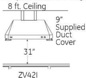
Example: Hood installation height with 8 ft. ceilings.
text_image
8 ft. Ceiling 9" Supplied Duct Cover 31" ZV421
text_image
8 ft. Ceiling 5" Supplied Duct Cover 31" ZV54I- Both models are shipped with a support frame and duct cover for 7'11" to 8'5" ceilings.
- If the ceiling height is 7'11", the installation height above the cooking surface will be 30".
- If the ceiling height is 8'5", the hood installation height will be 36".
DETERMINE INSTALLATION HEIGHT
- Measure the exact ceiling height.
- Review the chart to determine the range of hood installation heights that can be accomplished with or without an accessory kit.
text_image
Duct Cover 20" for ZV42I 24" for ZV54I 30" Min. and 36" Max. Ceiling Height 36" to CountertopACCESSORIES
ZX42DC10 - Optional Accessory for ZV42I. ZX54DC10 - Optional Accessory for ZV54I. Accessories for ceiling heights of 8'6" to 10'4". Includes telescoping support frames and duct covers.
Model ZV421
| Actual Ceiling Height | Chimney Length at Duct Hood Installation Height | Cover Kit | ||||||
| 30" | 31" | 32" | 33" | 34" | 35" | 36" | ||
| 10'4" | 36 | 35 | 34 | 33 | 32 | Order ZX42DC10Use Long Support and Duct Cover | ||
| 10'3" | 36 | 35 | 34 | 33 | 32 | 31 | ||
| 10'2" | 36 | 35 | 34 | 33 | 32 | 31 | 30 | |
| 10'1" | 35 | 34 | 33 | 32 | 31 | 30 | 29 | |
| 10' | 34 | 33 | 32 | 31 | 30 | 29 | 28 | |
| 9'11" | 33 | 32 | 31 | 30 | 29 | 28 | 27 | |
| 9'10" | 32 | 31 | 30 | 29 | 28 | 27 | 26 | |
| 9'9" | 31 | 30 | 29 | 28 | 27 | 26 | 25 | |
| 9'8" | 30 | 29 | 28 | 27 | 26 | 25 | 24 | |
| 9'7" | 29 | 28 | 27 | 26 | 25 | 24 | 23 | |
| 9'6" | 28 | 27 | 26 | 25 | 24 | 23 | 22 | Order ZX42DC10Use Short Support and Duct Cover |
| 9'5" | 27 | 26 | 25 | 24 | 23 | 22 | 21 | |
| 9'4" | 26 | 25 | 24 | 23 | 22 | 21 | 20 | |
| 9'3" | 25 | 24 | 23 | 22 | 21 | 20 | 19 | |
| 9'2" | 24 | 23 | 22 | 21 | 20 | 19 | 18 | |
| 9'1" | 23 | 22 | 21 | 20 | 19 | 18 | 17 | |
| 9' | 22 | 21 | 20 | 19 | 18 | 17 | 16 | |
| 8'11" | 21 | 20 | 19 | 18 | 17 | 16 | 15 | |
| 8'10" | 20 | 19 | 18 | 17 | 16 | 15 | ||
| 8'9" | 19 | 18 | 17 | 16 | 15 | |||
| 8'8" | 18 | 17 | 16 | 15 | ||||
| 8'7" | 17 | 16 | 15 | |||||
| 8'6" | 16 | 15 | ||||||
| 8'5" | 15 | 9 | Use Supplied Support and Duct Cover | |||||
| 8'4" | 9 | |||||||
| 8'3" | 9 | |||||||
| 8'2" | 9 | |||||||
| 8'1" | 9 | |||||||
| 8' | 9 | |||||||
| 7'11" | 9 | |||||||
Model ZV54I
| ActualCeilingHeight | Chimney Hood Installation Height | DuctCover | |||||||
| 30" | 31" | 32" | 33" | 34" | 35" | 36" | Kit | ||
| 10'4" | 28 | ||||||||
| 10'3" | 28 | 27 OrderZX54DC10Use LongSupportandDuct Cover | |||||||
| 10'2" | 28 | 27 | 26 | ||||||
| 10'1" | 28 | 27 | 26 | 25 | |||||
| 10' | 28 | 27 | 26 | 25 | 24 | ||||
| 9'11" | 28 | 27 | 26 | 25 | 24 | 23 | |||
| 9'10" | 28 | 27 | 26 | 25 | 24 | 23 | 22 | ||
| 9'9" | 27 | 26 | 25 | 24 | 23 | 22 | 21 | ||
| 9'8" | 26 | 25 | 24 | 23 | 22 | 21 | 20 | ||
| 9'7" | 25 | 24 | 23 | 22 | 21 | 20 | 19 | ||
| 9'6" | 24 | 23 | 22 | 21 | 20 | 19 | 18 | ||
| 9'5" | 23 | 22 | 21 | 20 | 19 | 18 | 17 | OrderZX54DC10Use ShortSupportandDuct Cover | |
| 9'4" | 22 | 21 | 20 | 19 | 18 | 17 | 16 | ||
| 9'3" | 21 | 20 | 19 | 18 | 17 | 16 | 15 | ||
| 9'2" | 20 | 19 | 18 | 17 | 16 | 15 | 14 | ||
| 9'1" | 19 | 18 | 17 | 16 | 15 | 14 | 13 | ||
| 9' | 18 | 17 | 16 | 15 | 14 | 13 | 12 | ||
| 8'11" | 17 | 16 | 15 | 14 | 13 | 12 | |||
| 8'10" | 16 | 15 | 14 | 13 | 12 | ||||
| 8'9" | 15 | 14 | 13 | 12 | |||||
| 8'8" | 14 | 13 | 12 | ||||||
| 8'7" | 13 | 12 | |||||||
| 8'6" | 12 | ||||||||
| 8'5" | 5 | UseSuppliedSupportandDuct Cover | |||||||
| 8'4" | 5 | ||||||||
| 8'3" | 5 | ||||||||
| 8'2" | 5 | ||||||||
| 8'1" | 5 | ||||||||
| 8' | 5 | ||||||||
| 7'11" | 5 | ||||||||
DUCT FITTINGS
Use this chart to compute maximum permissible lengths for duct runs to outdoors.
For best results, use 10" diameter duct.
Note: Do not exceed maximum permissible equivalent lengths!
Maximum recommended duct length for these hoods: 150 feet
Flexible ducting:
If flexible metal ducting is used, all the equivalent feet values in the table should be doubled. The flexible metal duct should be straight and smooth and extended as much as possible.
Do NOT use flexible plastic ducting.
Note: Any home ventilation system, such as a ventilation hood, may interrupt the proper flow of combustion air and exhaust required by fireplaces, gas furnaces, gas water heaters and other naturally vented systems. To minimize the chance of interruption of such naturally vented systems, follow the heating equipment manufacturer's guidelines and safety standards such as those published by NFPA and ASHRAE. When applicable, install any makeup (replacement) air system in accordance with local building code requirements. Visit GEAppliances.com for available makeup air solutions.
Hoods Are Equipped For 10" Round Duct
* Hoods are supplied with a 10" round transition. A locally supplied transition is required for other sizes.
Note: Outlet on top of hood is 8-1/8" × 8".
* Actual length of straight duct plus duct fitting equivalent. Equivalent length of duct pieces are based on actual tests conducted by GE Evaluation Engineering and reflect requirements for good venting performance with any ventilation hood.
| Duct Piece | Length* | Used | Equivalent Length | Quantity | Total |
 | |||||
 | 1(per foot length) | ft. | |||
 | 8" Dia. 52 ft.10" Dia. 24 ft. | ||||
 | 8" Dia. 31 ft.10" Dia. 14 ft. | ||||
 | 8" Dia. 99 ft.10" Dia. 41 ft. | ||||
 | 8" Dia. 136 ft.10" Dia. 56 ft. | ||||
Total Duct Run ____

text_image
TOOLS AND MATERIALS REQUIRED (NOT SUPPLIED) Pencil and tape measure Duct tape Wire cutter/ stripper 7/16" Pivoting hex socket with 4" and 6" extensions Hammer Key Hole Saw Electric or battery operated drill and 3/16", bits, Phillips and Flat Blade Screwdriver bits. Spirit level Safety glasses Wire nuts 10" round metal duct, length to suit installation. Step ladder Flashlight Saber saw or Sawsall Phillips and flat blade screwdrivers Strain relief for junction cover. Carpenter's square Pliers Metal Snips 120V 60Hz. 15 or 20 Amp, 2-wire with ground. Properly grounded branch circuit.REMOVE THE PACKAGING
- Remove the parts packages and packing materials.
- Lift the hood out of the box.
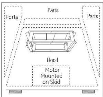
IMPORTANT: Lift the hood by grasping the outside edges of the exhaust opening on the top.
text_image
Parts Parts Hood Motor Mounted on SkidShipping Carton
- Place the hood on a protective surface to prevent scratches and damage to the stainless steel finish.
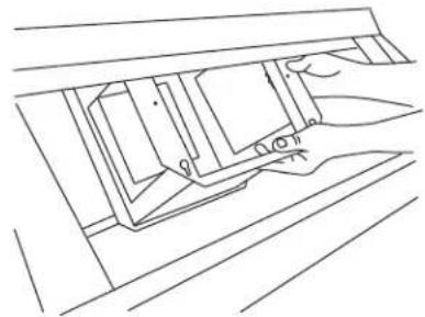
- Carefully, lay the hood on its side. A support frame is secured to the inside top of the hood. Remove the attachment screws at the outside top. Discard screws.
- Grasp the support frame inside the hood with both hands and carefully rotate out of the opening.
Be careful not to scratch the hood.
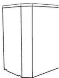
natural_image
Pure technical line drawing of a mechanical assembly without any text, numbers, or symbols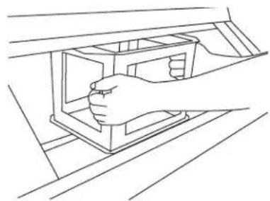
natural_image
Line drawing of a hand inserting a component into a box (no text or symbols)- The hood motor is shipped secured to the skid with 4 screws. Locate and remove 2 screws on each side of the motor. Discard the shipping skid and screws.
PARTS PROVIDED
Locate the parts packed with the hood.
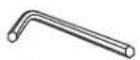
Allen Wrench

natural_image
Technical line drawing of a three parallel cylindrical components with four bullet tips below (no text or symbols)Implement rods with standoffs

natural_image
Pure line drawing of two symmetrical 3D geometric shapes with no text or symbols2 Grease trays (3 with 54" hood)

Duct collar
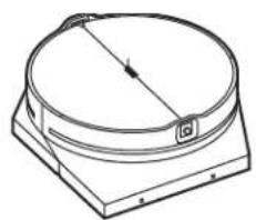
natural_image
Technical line drawing of a circular mechanical component with a base and top plate (no text or symbols)Transition with Damper
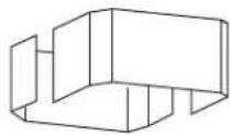
2-piece decorative duct cover

natural_image
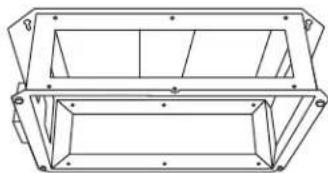
Two wooden slatted panels with metal fasteners, shown from different angles (no text or symbols)2 Filters (3 with 54" hood)
natural_image
Technical line drawing of a rectangular frame structure with mounting holes and internal ribs (no text or symbols)Support frame for 8 ft. ceiling with 4 large pan head screws installed on the bottom corners.
natural_image
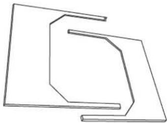
Abstract geometric line drawing of two overlapping angular shapes (no text or symbols)Decorative top cover
HARDWARE PACKAGE
Locate and check contents. Screws shown actual size.

Screws A
4(7/16")
hex head
wood
screws

text_image
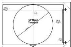
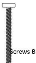
54" Board TempletsScrews B
2 (1/8" × 1-1/2")
Phillips
pan head
screws.
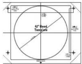
text_image
42" Flood Template2 Templates
|


Screws D
2 small
Phillips
head
screws

Screws C
8 blunt point
Phillips
screws
illips

Screws E
2 Phillips
head wood
screws
Screw F
Blower safety screw and lock washer,
Phillips head M 6 x 16.
Note: Hardware appearance may vary slightly.
ACCESSORY PACKAGE
Check accessory package.
Select the taller set for 9'6" to 10'4" ceilings.
Select the shorter set for 8'6" to 9'6" ceilings.
Discard unused set.
natural_image
Simple line drawing of a 3D rectangular prism with vertical and horizontal lines (no text or symbols)2 Sets of Duct Covers
2 Support Frames
with 8 height
adjustment
screws

natural_image
Diagram of a multi-tiered vertical cabinet or rack structure with dashed alignment lines, no text or symbols present.4 Attachment Screws
STEP 1 CONSTRUCT CEILING SUPPORT
Plan the Location of the Hood and Ductwork
- Use a plumb bob to check the location. The countertop/cooktop below the hood must be centered with the hood.

text_image
Ceiling Hood Ducting Centerline Front 15-7/8" 31-3/4" Align With Center of Cooktop Cooktop Countertop 42" Hood Side View- The hood should extend beyond the front and rear edge of the cooking appliance. - The duct in the ceiling must be centered over the cooktop.
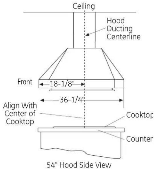
text_image
Ceiling Hood Ducting Centerline Front 18-1/8" 36-1/4" Align With Center of Cooktop Cooktop Counter 54" Hood Side ViewCeiling Support Structure
- At the hood location, install 2 x 4 cross framing between ceiling joists as shown. (2x4's are required to support the weight of the hood.)
- Arrange cross framing in the ceiling to suit the existing structure.
- Your ceiling joists will be like one of the following examples.

text_image
EXAMPLE A 12-3/4" (42" Hood) 17" (54" Hood) Install Cross-Framing Symmetrically About Duct/Cooktop Centerline 16" Joist Spacing 8 5/8" 10" Duct 2x4 Cross Framing Front of Hood Align duct to center of Cooktop Cooktop OutlineTop View – Ceiling Joists Parallel to Front of Hood
STEP 1 CONSTRUCT CEILING SUPPORT CONTINUED
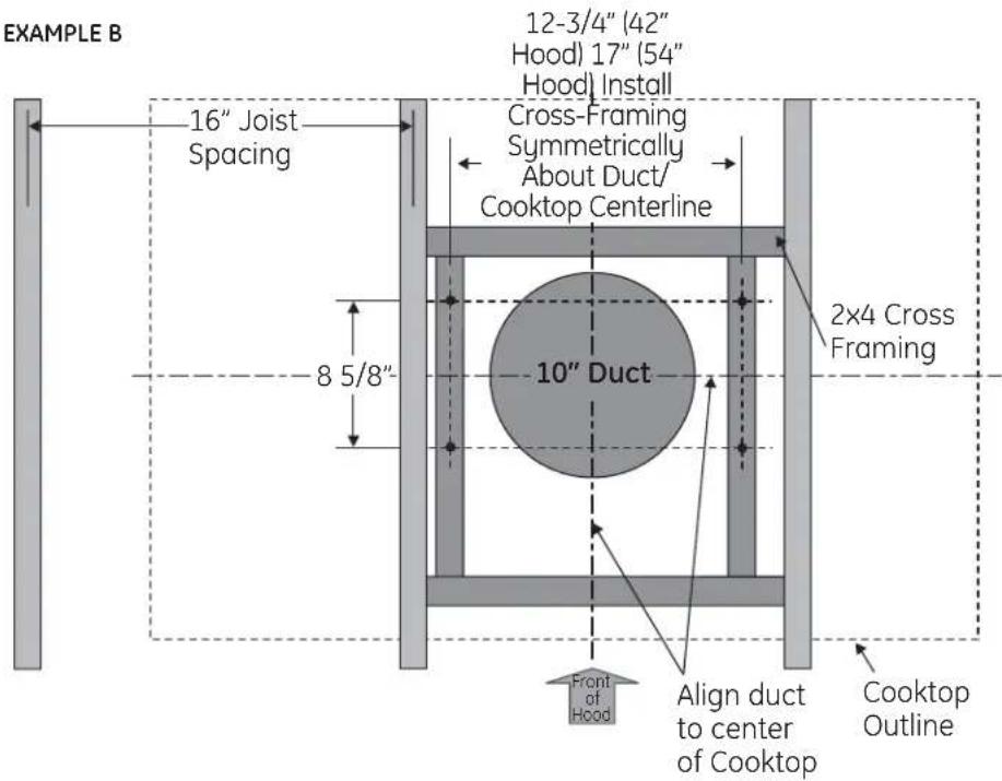
text_image
EXAMPLE B 16" Joist Spacing 8 5/8" 12-3/4" (42" Hood) 17" (54" Hood) Install Cross-Framing Symmetrically About Duct/ Cooktop Centerline 10" Duct 2x4 Cross Framing Front of Hood Align duct to center of Cooktop Cooktop OutlineTop View – Ceiling Joists Run Perpendicular to Front of Hood
EXAMPLE C

text_image
12-3/4" (42" Hood) 17" (54" Hood) Install Cross-Framing Symmetrically About Duct/Cooktop Centerline 8 5/8" 10" Duct 2x4 Cross Framing 16" Joist Spacing Front of Hood Align duct to center of Cooktop Cooktop OutlineTop View - Ceiling Joists at Angle with Front of Hood
STEP 1 CONSTRUCT CEILING SUPPORT CONTINUED
- Secure each 2 x 4 block with at least four (4), #10 wood screws, 3" long (not supplied). Use 8 wood screws total for the two supports.
- The cross framing must be accurately aligned to assure correct positioning of the hood.
- The cross framing must be level in all directions. Check with a spirit level and adjust if necessary.
IMPORTANT: The ceiling structure must be capable of supporting the weight of the hood (approximately 300 pounds) and any inadvertent user contact loads. The hood support frame will be supported by the 2 x 4 cross framing.

text_image
2x 4 Min. Cross Framing Ceiling Joist 8-5/8" 17" (54" Hoo) 12-3/4" (42" Hoo) Height Adjustmen Screw HoleDuctwork
- Use the shortest and straightest duct route possible. For satisfactory performance, duct run should not exceed 150 feet equivalent length for any duct configuration.
- Refer to "Duct Fittings" chart to compute the maximum permissible length for duct runs to the outdoors.
- This vent hood must use 10" round rigid duct.
• Install the house ductwork to run horizontally between ceiling joists or straight up through the roof.
Finish the Ceiling
- Finish the ceiling surface. Be sure to mark location of the ceiling joists and cross framing. Check to be sure the ceiling is level, use shims if necessary.
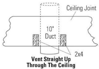
text_image
Ceiling Joint 10" Duct 2x4 Vent Straight Up Through The CeilingSTEP 2 MOUNT TEMPLATE
- Select the template for your hood size.
- Align the template with the marks on the ceiling and tape in place.
- Be sure the template is oriented correctly, with the front of the hood.
- Use a plumb to check to be sure the mounting holes will provide parallel alignment with the countertop below.
• Center punch all hole locations. - Drill pilot holes in the 4 screw locations. Use a 3/16" bit and drill approximately 1-1/2" deep.
- Drive 4 Hex head wood screws (Screws A) into the center of the ceiling joists and cross framing. Leave a 1/4" gap to allow the screw head to engage the keyhole slots on the support frames.
- Cut the 10-1/2" duct opening through the sheet rock.

STEP 3 SIZE AND INSTALL DUCTWORK
- Measure from house duct flange to bottom of support frame. Subtract 4-3/8" for clearance to the bottom of the support frame.
- Cut the 10" duct length to size.
- Secure duct to house ducting with sheet metal screws.
- Seal all connections with duct tape.
- Attach the duct collar loosely, about 1" from the bottom of the duct using Screws B.

text_image
House Duct Duct Duct Duct Collar 4-3/8" Clearance to Bottom of FramSTEP 4 INSTALL ACCESSORY (OR SUPPLIED) SUPPORT AND DUCT COVERS

text_image
Install Safety Screw on Each Side Screws E Adjust Frame to installation Height Install Small Pan Head Screws on Each Side Top Duct Cover Bottom Duct Cover Screws D Install Stop Screw Stop Screw Storage LocationInstall supplied support frame OR telescoping accessory frame
- Hang the supplied support frame or telescoping accessory frame to the ceiling joists and cross framing on the 4 hex head screws by engaging the keyhole slots on the frame.
- Check to be sure the support frame is level, vertically and horizontally.
- Tighten the hex head screws securely.
• Install safety screws, (Screws E) on each side of the frame.
Adjust telescoping accessory frame to length
- Remove the 8 frame adjustment screws. Adjust the lower support up or down to the pre-determined length. Reinstall and securely tighten the 8 adjustment screws.
- Slide the top (inner) accessory duct cover up and over the frame. Secure the duct cover to the frame as shown using Screws D.
- Locate and remove the safety stop screw. Slide bottom duct cover up and over the top duct cover. Align bottom duct screw hole to the hole in the frame. Hold the duct cover in place while installing screw.
CAUTION: The stop screw
must be installed. Failure to do so could result in personal injury or damage to the duct cover. The stop screw will prevent the lower duct from sliding down while completing the installation.
APRUDENCE
- Route house wiring through the ceiling and pull a length to reach the hood junction box, approximately 6" below the support. Tape to the right side of the support frame.
IMPORTANT: Again, check to be sure the support is level in both directions. There is no way to level the hood after the hood is secured to the frame.
STEP 5 INSTALL DUCT TRANSITION WITH DAMPER

text_image
Bumper Pads Duct Transition Attachment Screws Screws CIMPORTANT: Remove shipping tape from damper and check that damper moves freely.
- Place the transition piece over the hood exhaust and secure with 4 Screws C provided.
- Use duct tape to seal the connection. Check to be sure the damper moves freely.
STEP 6 INSTALL HOOD
Note: THREE PEOPLE ARE REQUIRED TO COMPLETE THIS INSTALLATION!

text_image
1/4" Gap Attachment Keyholes- Back out the hanging screws on the bottom of the support frame to a 1/4" gap.
- Lift the hood up to the support frame. Carefully align the hood keyhole to the screws on the support frame. Slide the hood to engage the keyhole slots.
- Tighten the screws.

Screws C

text_image
Install 2 Safety Screws• Install safety screws into the top of the hood as shown.
- Check hood level in both directions.
STEP 7 CONNECT DUCT
- Loosen duct collar and slide down to cover
gap between transition and house duct. Tighten collar screws and tape all joints.
- Seal all connections with duct tape.
Note: Do not drive screws through this duct connection. Doing so will prevent proper damper operation.

text_image
Slide Duct Collar Down to Cover GapSTEP 8 CONNECT ELECTRICAL
Verify that power is turned off at the source.
WARNING: If house wiring is not 2-wire with a ground wire, a ground must be provided by the installer. When house wiring is aluminum, be sure to use UL approved anti-oxidant compound and aluminum-to-copper connectors.
• Install strain relief onto the knockout of the junction box.
- Insert house wiring through strain relief and tighten.
- Use wire nuts to connect incoming ground to green, white to white and black to black.
- Push wires into junction box and replace cover. Be sure wires are not pinched.
STEP 9 INSTALL THE MOTOR
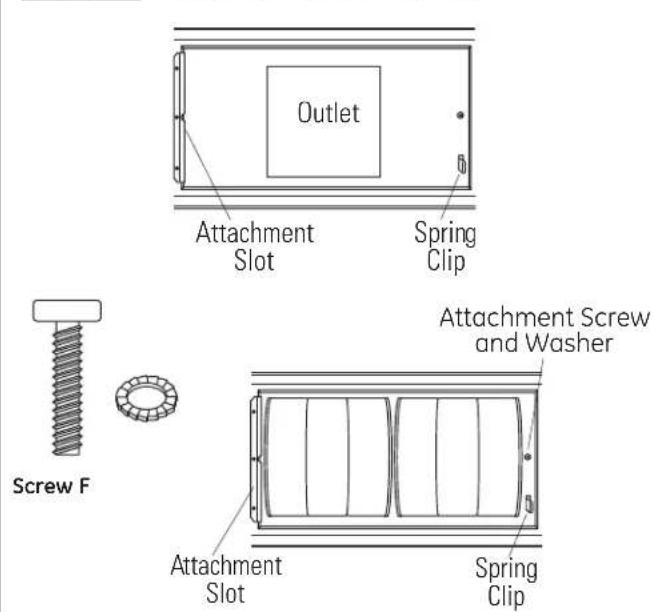
text_image
Outlet Attachment Slot Spring Clip Screw F Attachment Screw and Washer Attachment Slot Spring Clip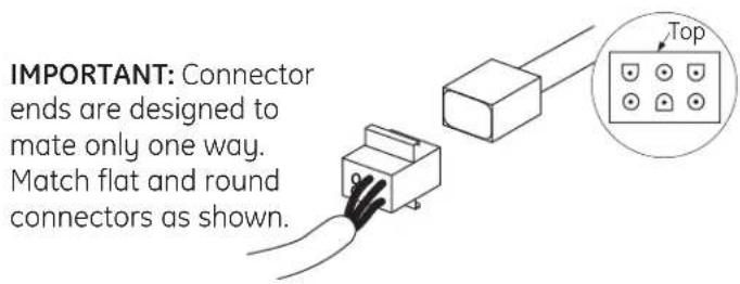
text_image
IMPORTANT: Connector ends are designed to mate only one way. Match flat and round connectors as shown.- From the inside of the hood, slip motor into the attachment slot on the left.
- Rotate motor upwards until it snaps into the spring clip on the right.
- Secure the motor to the hood with the machine screw and lock washer (Screw is marked with red paint.)
- Plug blower cable into the connector on the blower.

text_image
Junction Box- Plug cable at the top of the hood into the junction box connector. Route cable so it won't be pinched or damaged when the duct cover is lowered.
STEP 10 SLIDE DUCT COVER DOWN
SKIP THIS STEP IF USING THE SUPPLIED DUCT COVER
- Hold the duct cover in place and remove the temporary stop screw. Return the screw to the storage location for future use.
- Slide the lower duct cover down onto the hood.
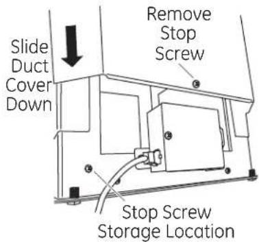
text_image
Slide Duct Cover Down Remove Stop Screw Stop Screw Storage LocationSTEP 12 INSTALL RODS
- Use a flat blade screwdriver to install stand-offs into the bottom of the hood.
- Align implement rod to stand-offs with the screw hole towards the inside of the hood. Secure the rod to the stand-offs with the supplied Allen wrench.
- Follow the same procedure on the opposite side.
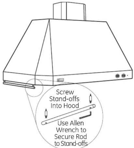
text_image
Screw Stand-offs Into Hood Use Allen Wrench to Secure Rod to Stand-offsSTEP 11 INSTALL FILTERS
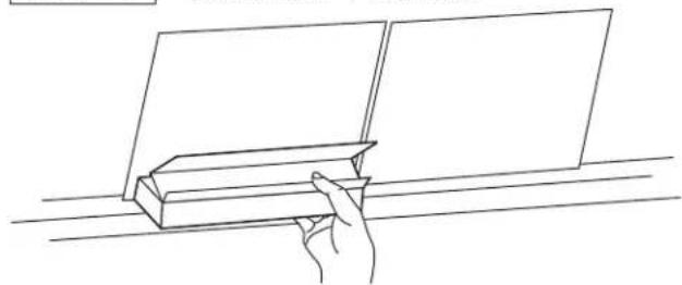
natural_image
Line drawing of a hand holding a rectangular object on a surface, with no text or symbols present.- Place filter drip trays into the rear of the hood.
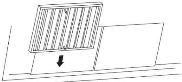
natural_image
Simple line drawing of a panel with vertical bars and a downward arrow, no text or symbols present- Insert the filter into the upper opening and drop into the trays.
- To remove the filters, grasp the knobs and push the filter up and lift out.
STEP 13 INSTALL SUPPLIED DUCT COVER AND TOP COVER


text_image
Install Duct Cover Screw on Each Side- Install the supplied 2-piece duct cover over the support frame (if using supplied frame). Snap ends together.
- Secure duct covers to support frame with 2 Screws D.
- For a more finished appearance, a top cover is supplied and should be installed whenever the top of the hood is visible.
TIP: Place pieces of tape over ends of the cover to prevent scratching the duct cover. Remove tape before installing screws.
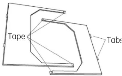
text_image
Tape Tabs- Engage tabs into slots on each side at the top of the hood. The covers should lay flat in the impression on top of the hood.

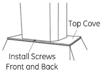
text_image
Top Cove Install Screws Front and Back- Install 2 Screws C to secure the cover to the hood at the front and back.
STEP 14 FINALIZE INSTALLATION
- Check all lamps to assure tightness in sockets.
- Turn power on at the circuit breaker.
- Refer to the Owner's Manual for operating and cleaning instructions.
STEP 15 INSTALLATION CHECKLIST
Check Blower Safety Screw
☐ Ensure that blower safety screw is securely tightened. See page 16, Step 9. If screw is missing, order replacement parts bag.
Check Operating Sound and Proper Air-Flow
☐ Turn blower to each speed setting and listen for rattles and vibration. You should notice an audible difference at each speed setting.
□ Check for foreign material in transition.
☐ Check that blower screen is not damaged or pushed into the blower impeller.
☐ The damper should move freely. Listen for opening and closing while turning the unit on and off.
☐ Check that the damper is not damaged, does not vibrate and that damper bumper pads are in place. Order a damper replacement assembly if needed.
☐ Check that ductwork is 10" round. If duct type is not rigid and less than 10" round, inform the consumer that performance will be reduced.
Check Lighting Function
☐ Check that power cable is plugged into the junction box on top of the hood.
☐ Turn halogen lamps to each setting. Note change in brightness at different settings.
☐ Check that each lamp bezel is secure. Turn to the right to tighten. Order replacement lamp bezel and socket assemblies if needed.
Check appearance and installation
☐ Use a spirit level to check that the hood is level. Review installation instructions to determine source of problem.
☐ Top covers (if used) should lay flat in the recess on top of the hood. Make sure side tabs are engaged in slots and the cover is secured with two screws.
□ Clean the hood surfaces and all filters. See the Owner's Manual for cleaning instructions. They should be free of construction debris such as sawdust.
Note: While performing installations described in this book, safety glasses or goggles should be worn.
For Monogram® local service in your area, call 1.800.444.1845.
Note: Product improvement is a continuing endeavor at General Electric. Therefore, materials, appearance and specifications are subject to change without notice.
49-80209-5
02-13 GE
Printed in Mexico

GE Appliances & Lighting
Appliances
General Electric Company
Louisville, KY 40225
GEAppliances.com