GXVR55840 - Radio scanner UNIDEN - Free user manual and instructions
Find the device manual for free GXVR55840 UNIDEN in PDF.

User questions about GXVR55840 UNIDEN
0 question about this device. Answer the ones you know or ask your own.
Ask a new question about this device
Download the instructions for your Radio scanner in PDF format for free! Find your manual GXVR55840 - UNIDEN and take your electronic device back in hand. On this page are published all the documents necessary for the use of your device. GXVR55840 by UNIDEN.
USER MANUAL GXVR55840 UNIDEN
System Configurations
Please read the following notes prior to using your Device.
NOTE
- The interfaces in the Manual are used for introducing the operations and only for reference. The actual interface might be different dependent on the model you purchased. If there is inconsistency between the Manual and the actual product, the actual product shall govern.
- The Manual is a general document for introducing the product, so there might be some functions described for the Device in the Manual not apply to the model you purchased.
- Conventions for mouse operations on a menu.
◇ Click: On the menu, left-click the mouse once on an option to enter the option setting.
Right-click: On any interface, right-click the mouse once to return to the previous level.
Initial Settings
Booting up

CAUTION
- Ensure the input voltage corresponds to the power requirement of the Device. Power on the Device after the power cable is properly connected.
- To protect the Device, please connect the Device with the power cable first, and then connect to the power source.
Step 1 Connect the Device to the monitor.
Step 2 Plug in the power cable to the Device.
Step 3 Press the power button to turn on the Device. The power indicator light is on. On the connected monitor, the live view screen is displayed by default. If you turn on the Device during the time period that is configured for recording, the system starts recording after it is turned on, and you will see the icon indicating recording status is working in the specific channels.
Initializing the Device
When booting up for the first time, you need to configure the password information for admin (by default).
NOTE
To secure the Device, it is strongly recommended for you to properly keep the password for admin and modify it regularly.
Step 1 Turn on the Device.
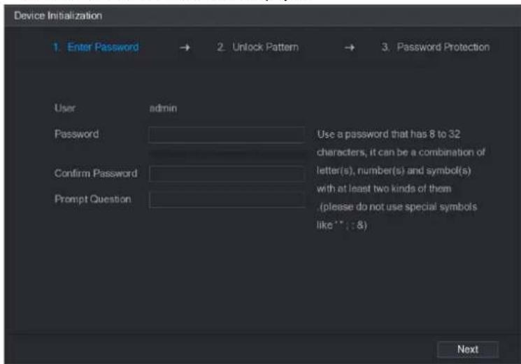
The Device Initialization interface is displayed.
text_image
Device Initialization 1. Enter Password → 2. Unlock Pattern → 3. Password Protection User admin Password Use a password that has 8 to 32 characters, it can be a combination of letter(s), number(s) and symbol(s) with at least two kinds of them (please do not use special symbols like * : 8) Confirm Password Prompt QuestionStep 2 Configure the password information for admin.
| Parameter | Description |
| User | By default, the user is admin. |
| Password | In the Password box, enter the password for admin.The new password can be set from 8 characters through 32 characters and contain at least two types from number, letter and special characters (excluding "", "", ":", ":" and "&"). |
| Confirm Password | |
| Prompt Question | In the Prompt Question box, enter the information that can remind you of the password.NOTEOn the login interface, click the prompt will display to help you find back the password. |
Step 3 Click Next.
The unlock pattern setting interface is displayed.

text_image
Device Initialization 1. Enter Password → 2. Unlock Pattern → 3. Password Protection Please draw the unlock pattern. Back SkipStep 4 Draw a unlock pattern.
After the setting is completed, the password protection settings interface is displayed.

NOTE
• The pattern that you want to set must cross at least four points.
• If you do not want to configure the unlock pattern, click Skip.
- Once you have configured the unlock pattern, the system will require the unlock pattern as the default login method. If you skip this setting, enter the password for login.
text_image
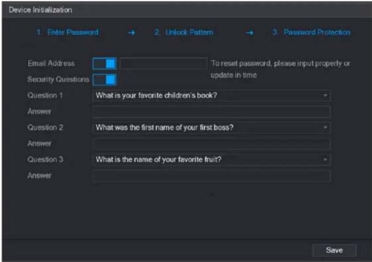
Device Initialization 1. Enter Password → 2. Unlock Pattern → 3. Password Protection Email Address To reset password, please input properly or Security Questions update in time Question 1 What is your favorite children's book? Answer Question 2 What was the first name of your first boss? Answer Question 3 What is the name of your favorite fruit? Answer SaveStep 5 Configure the protection parameters for password.
After configuration, if you forgot the password for admin user, you can reset the password through the reserved email address or security questions.
If you do not want to configure the settings, disable the email address and security questions functions on the interface.
| Password Protection Mode | Description |
| Email Address | Enter the reserved email address.In the Email Address box, enter an email address for password reset. In case you forgot password, enter the security code that you will get from this reserved email address to reset the password of admin. |
| Security Questions | Configure the security questions and answers.In case you forgot password, enter the answers to the questions can make you reset the password. |
| NOTEIf you want to configure the email or security questions function later or you want to change the configurations, select Main Menu > ACCOUNT > USER. | |
Step 6 Click Save to complete the settings.
The End-User License Agreement interface is displayed.
Step 7 Select the I have read and agree to all terms check box.
Step 8 Click Next.
The Startup Wizard interface is displayed.
Resetting Password
You can reset the password through the QR code or the security questions.
- To reset through the QR code, make sure the Enable check box is selected in Main Menu > SYSTEM > SECURITY > Password Reset.
-
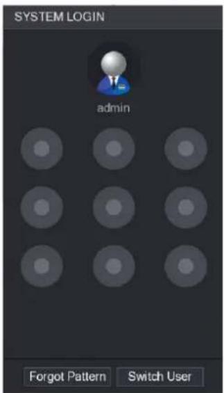
To reset through the security questions, make sure the security quesitons is configured. Step 1 Enter the login interface.
-
If you have configured unlock pattern, the unlock pattern login interface is displayed.
- If you did not configure unlock pattern, the password login interface is displayed.
NOTE
On the unlock pattern login interface, click Switch User to login; or on the password login interface, in the User Name list, select other users to login.
text_image
SYSTEM LOGIN admin Forgot Pattern Switch User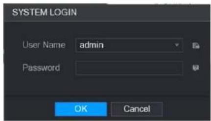
text_image
SYSTEM LOGIN User Name admin Password OK CancelStep 2 Click

- If you did not set the reserved email address, the email entering interface is displayed. Enter the email address, and then click Next, the Reset the password interface is displayed.
- If you have set the reserved email address, the Reset the password interface is displayed.

text_image
Reset the password Reset Type QR Code Email Address To reset password, please input properly or update in time Next Cancel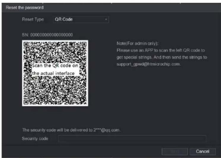
text_image
Reset the password Reset Type QR Code SN: 000000000000000000 Scan the QR code on the actual interface Note(For admin only): Please use an APP to scan the left QR code to get special strings. And then send the strings to support_gpwd@htmlcrochip.com. The security code will be delivered to 2***@qq.com. Security code Next CancelStep 3 Rest the password.
- QR code
Follow the onscreen instructions to get the security code in your reserved email address. In the Security code box, enter the security code.

CAUTION
- You are given the limited times to get the security code by scanning the QR code within 24 hours. Please operate carefully.
- Please use the security code received in your email box to reset the password within 24 hours; otherwise the security code becomes invalid.
• Security questions
1) On the Reset the password interface as shown, in the Reset Type list, select Security Questions, the Security Questions interface is displayed.
NOTE
If you did not configure the security questions before, in the Reset Type list, there will be no Security Questions.
2) In the Answer box, enter the correct answers.

text_image
Reset the password Reset Type Security Questions Question 1 What is your become children's book? Answer Question 2 What was the list name to your best book? Answer Question 3 What is the name or your favorite but? Answer Next CancelStep 4 Click Next.
The new password resetting interface is displayed.
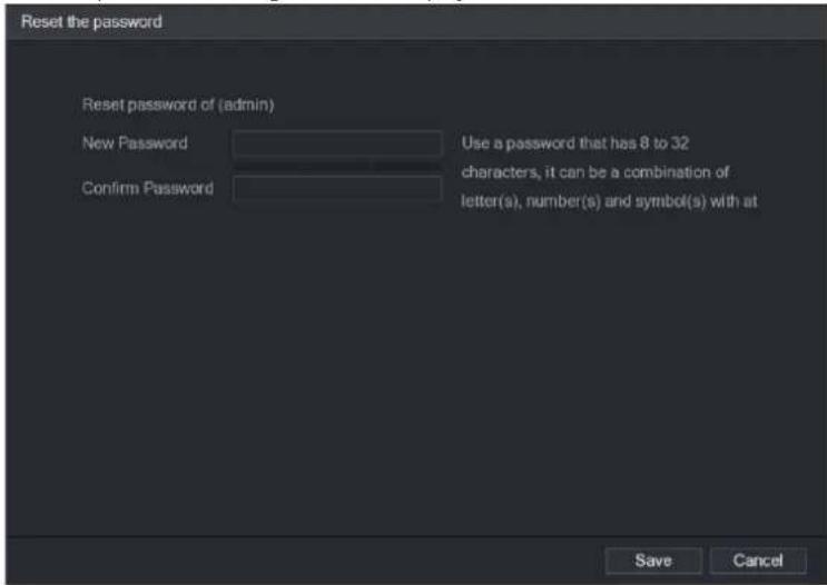
text_image
Reset the password Reset password of (admin) New Password Use a password that has 8 to 32 Confirm Password characters, it can be a combination of letter(s), number(s) and symbol(s) with at Save CancelStep 5 In the New Password box, enter the new password and enter it again in the Confirm Password box.
Step 6 Click Save. The password resetting is started.
After resetting is completed, a pop-up message is displayed.
Step 7 Click OK
A pop-up message is displayed asking if you want to sync the password with the remote devices.
- Click Cancel, the resetting is finished.
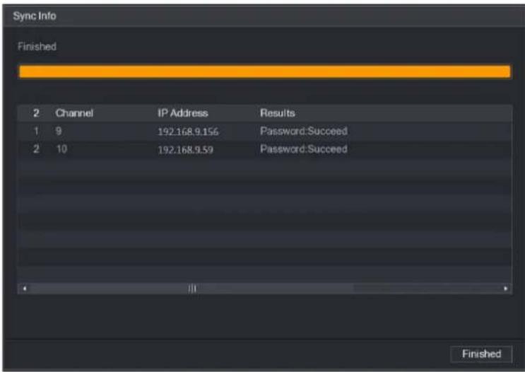
- Click OK, the Sync Info interface is displayed.

text_image
Reset the password Reset password of (admin) New Password Use a password that has 8 to 32 Confirm Pass Message Do you want to sync Password with the remote device connecting via the default protocol? OK Cancel Save Cancel
NOTE
This message appears only when there are digital channels instead of complete analog channels.
text_image
Sync Info Finished 2 Channel IP Address Results 1 9 192.168.9.156 Password:Succeed 2 10 192.168.9.59 Password:Succeed FinishedSetting Up with the Startup Wizard
Entering Startup Wizard
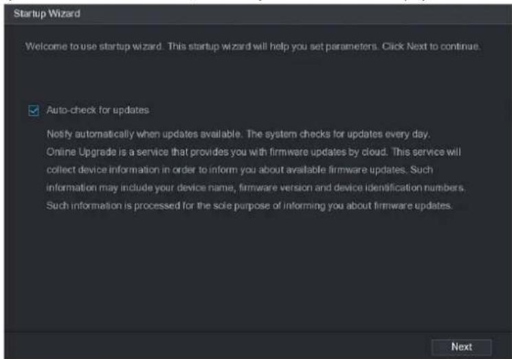
The Startup Wizard helps you configure the basic settings to set up the Device. After you have initialized the Device, the Startup Wizard interface is displayed.
text_image
Startup Wizard Welcome to use startup wizard. This startup wizard will help you set parameters. Click Next to continue. ✓ Auto-check for updates Notify automatically when updates available. The system checks for updates every day. Online Upgrade is a service that provides you with firmware updates by cloud. This service will collect device information in order to inform you about available firmware updates. Such information may include your device name, firmware version and device identification numbers. Such information is processed for the sole purpose of informing you about firmware updates.
NOTE
If you select the Auto-check for updates check box, the system will notify you automatically when updates are available.
Configuring General Settings
You can configure the general settings for the Device such as Device name, language, and settings for instant playback.
You can also configure general settings by selecting Main Menu > SYSTEM > GENERAL > General.
Step 1 On the Startup Wizard interface, click Next.
The General interface is displayed.

text_image
General Device Name XVR Device No: 8 Language ENGLISH Video Standard NTSC Instant Play(Min.) 5 Auto Logout(Min.) 10 Monitor Channel(s) when logout Navigation Bar Mouse Sensitivity - + 850 Back NextStep 2 Configure the general settings parameters.
| Parameter | Description |
| Device Name | In the Device Name box, enter the Device name. |
| Device No. | In the Device No. box, enter a number for the Device. |
| Language | In the Language list, select a language for the Device system. |
| Video Standard | In the Video Standard list, select PAL or NTSC according to your actual situation. |
| Instant Play (Min.) | In the Instant Play box, enter the time length for playing back the recoded video. The value ranges from 5 to 60.On the live view control bar, click the instant playback button to play back the recorded video within the configured time. |
| Auto Logout (Min.) | In the Auto Logout box, enter the standby time for the Device. The Device automatically logs out when it is not working for the configured time period. You need to login the Device again.The value ranges from 0 to 60. 0 indicates there is not standby time for the Device.Click Monitor Channel(s) when logout. You can select the channels that you want to continue monitoring when you logged out. |
| Navigation Bar | Enable the navigation bar. When you click on the live view screen, the navigation bar is displayed. |
| Mouse Sensitivity | Adjust the speed of double-click by moving the slider.The bigger the value is, the faster the double-clicking speed must be. |
Configuring Date and Time Settings
You can configure the system time, choose the time zone, set the daylight saving time, and enable the NTP server.
You can also configure date and time settings by selecting Main Menu > SYSTEM >
GENERAL > Date&Time.
Step 1 After you have configured the general settings, on the General interface, click Next.
The Date&Time interface is displayed.
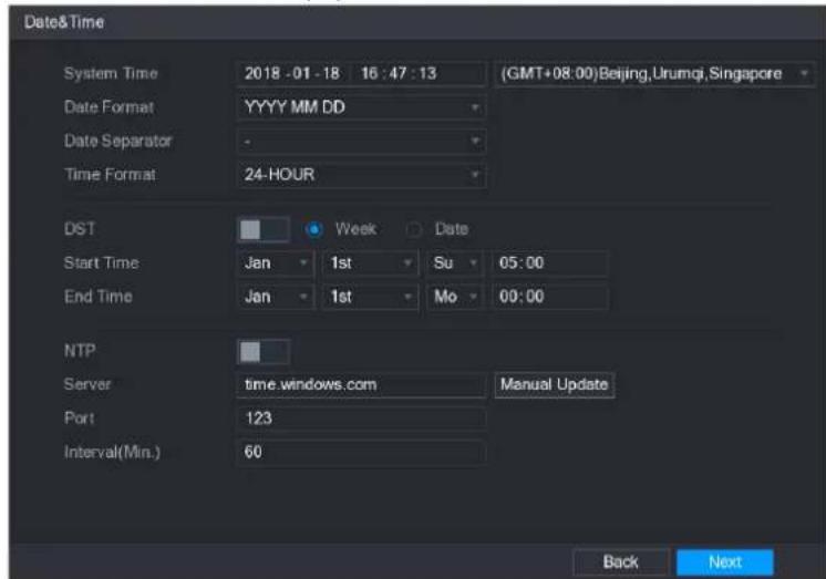
text_image
Date&Time System Time 2018 -01 -18 16 : 47 : 13 (GMT+08:00)Beijing,Urumqi,Singapore Date Format YYYY MM DD Date Separator - Time Format 24-HOUR DST Week Date Start Time Jan 1st Su 05:00 End Time Jan 1st Mo 00:00 NTP Server time.windows.com Manual Update Port 123 Interval(Min.) 60 Back NextStep 2 Configure the settings for date and time parameters.
| Parameter | Description |
| System Time | In the System Time box, enter time for the system.Click the time zone list, you can select a time zone for the system, and the time in adjust automatically.CAUTIONDo not change the system time randomly; otherwise the recorded video cannot be searched. It is recommended to avoid the recoding period or stop recording first before you change the system time. |
| Date Format | In the Date Format list, select a date format for the system. |
| Date Separator | In the Date Separator list, select a separator style for the date. |
| Time Format | In the Time Format list, select 12-HOUR or 24-HOUR for the time display style. |
| DST | Enable the Daylight Saving Time function. Click Week or click Date. |
| Start Time | Configure the start time and end time for the DST. |
| End Time | |
| NTP | Enable the NTP function to sync the Device time with the NTP server. |
| Server | In the Server box, enter the IP address or domain name of the corresponding NTP server.Click Manual Update, the Device starts syncing with the server immediately. |
| Port | The system supports TCP protocol only and the default setting is 123. |
| Interval (Min.) | In the Interval box, enter the amount of time that you want the Device to sync time with the NTP server. The value ranges from 0 to 65535. |
Configuring P2P Settings
You can add the Device into your cell phone client or the platform to manage.
You can also configure P2P function by selecting Main Menu > NETWORK > P2P.

Make sure the DVR is connected into the Internet, and if yes, in the Status box of the P2P interface, it shows Online.
Step 1 After you have configured the network settings, on the NETWORK interface, click Next.
The P2P interface is displayed.

text_image
P2P Enable Status Offline Cell Phone Client Scan the QR code on the actual interface Device SN Scan the QR code on the actual interface Back NextStep 2 Enable the P2P function.
Step 3 Click Apply.
You can start adding the device.
- Cell Phone Client: Use your mobile phone to scan the QR code to add the device into the Cell Phone Client, and then you can start accessing the Device.
- Platform: Obtain the Device SN by scanning the QR code. Go to the P2P management platform and add the Device SN into the platform. Then you can access and manage the device in the WAN.

NOTE
You can also enter the QR code of Cell Phone Client and Device SN by clicking on the top right of the interfaces after you have entered the Main Menu.

To use this function, take adding device into Cell Phone Client as an example.
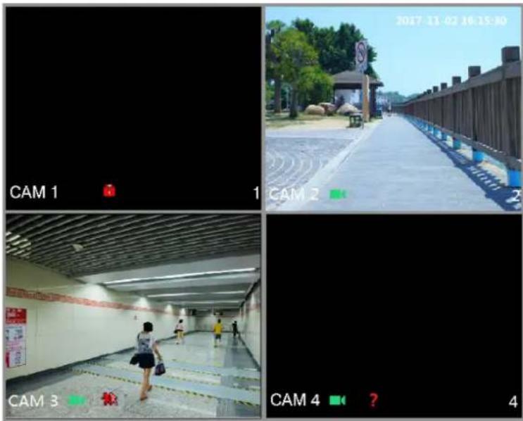
Live View
After you logged in the Device, the live view is displayed.
To enter the live view screen from other interfaces, click on the top right of the screen.
text_image
CAM 1 CAM 2 CAM 3 CAM 4 2017-11-02 16:15:30 CAM 4 ? 4Live View Screen
You can view the live video from the connected cameras through each channel on the screen.
- By default, the system time, channel name and channel number are displayed on each channel window. This setting can be configured by selecting Main Menu > CAMERA > OVERLAY.
- The figure in the bottom right corner represents channel number. If the channel position is changed or the channel name is modified, you can recognize the channel number by this figure and then perform the operations such as record query and playback.
For the icons displayed on each channel.
| Icon | Function |
| Indicates recording status. This icon displays when the video is being recorded. | |
| This icon displays when the motion detection occurs in the scene. | |
| This icon displays when the video loss is detected. | |
| This icon displays when the channel monitoring is locked. |

To switch the position of two channels, point to one of the two channels, and then drag the window to the other channel.
Live View Control bar
The live view control bar provides you access to perform the operations such as playback, zoom, real-time backup, manual snapshot, voice talk, adding remote devices, and streams switch.
When you move the pointer to the top middle position of a channel window, the live view control bar is displayed.

If there is not operation for six seconds after the control bar is displayed, the control bar hides automatically.

text_image
1 2 3 4 5 CAM 3| No. | Function | No. | Function |
| 1 | Instant Play | 4 | Manual Snap |
| 2 | Digital Zoom | 5 | Mute |
| 3 | Real-time Backup | ||
Instant Playback
You can play back the previous five minutes to sixty minutes of the recorded video.
By clicking, the instant playback interface is displayed. The instant playback has the
following features:
- Move the slider to choose the time you want to start playing.
- Play, pause and close playback.
- The information such as channel name and recording status icon are shielded during instant playback and will not display until exited.
- During playback, screen split layout switch is not allowed.
- To change the playback time, select Main Menu > SYSTEM > GENERAL, in the Instant Play box, enter the time you want to play back.

text_image
SYSTEM GENERAL General Date&Time Holiday PS232 SECURITY SYSTEM MAINTAIN IMP/EXP DEFAULT UPGRADE Device Name XVR Device No. 8 Language ENGLISH Video Standard PAL Instant Play(Min.) 5 Auto Logout(Min.) 2 IPC Time Sync 24 IPC Time Sync Period (hour) Navigation Bar Mouse Sensitivity - + 850 Monitor Channel(s) when logout Apply BackDigital Zoom
You can enlarge a specific area of the image to view the details by either of the following two ways.
- Click 📋, the icon switches to 🔒. Hold down the left mouse button to select the area you want to enlarge. The area is enlarged after the left mouse button is released.
- Point to the center that you want to enlarge, rotate the wheel button to enlarge the area.
NOTE
- For some models, when the image is enlarged in the first way described previously, the selected area is zoomed proportionally according to the window.
- When the image is in the enlarged status, you can drag the image toward any direction to view the other enlarged areas.
- Right-click on the enlarged image to return the original status.
Real-time Backup
You can record the video of any channel and save the clip into a USB storage device.
By clicking the recording is started. To stop recording, click this icon again. The clip is automatically saved into the connected USB storage device.
Manual Snapshot
You can take one to five snapshots of the video and save into a USB storage device.
By clicking you can take snapshots. The snapshots are automatically saved into the connected USB storage device. You can view the snapshots on your PC.
NOTE
To change the quantity of snapshots, select Main Menu > CAMERA > ENCODE > Snapshot, in the Manual Snap list, select the snapshot quantity.
Mute (Analog channel only)
You can mute the video sound by clicking 📄 This function is supported in single-channel view.
Navigation Bar
You can access the functions to perform operations through the function icons on the navigation bar. For example, you can access Main Menu and switch window split mode.
NOTE
The navigation bar is disabled by default. It does not appear in the live view screen until it is enabled. To enable it, select Main Menu > SYSTEM > GENERAL, enable the Navigation Bar, and then click Apply.
| Icon | Function |
| [KKZW] | Open Main Menu. |
| [QT73] | Expand or condense the navigation bar. |
| [SYXC] | Select view layout. |
 | Go to the previous screen. |
| [ZYH7] | Go to the next screen. |
| [74KB] | Enable tour function. The icon switches to [IMAGE] |
| [02ZD] | Open the PTZ control panel. |
| [2TH0] | Open theColor Settinginterface.[IMAGE]NOTEThis function is supported only in single-channel layout. |
 | Open the record search interface. |
 | Open theEVENTinterface to view the device alarm status. |
 | Open theCHANNEL INFOinterface to display the information of each channel. |
| [24DG] | Open theCAMERA REGISTRATIONinterface. |
| [75DS] | Open theNETWORKinterface. |
| [6ZHH] | Open theHDD MANAGERinterface. |
 | Open theUSB MANAGERinterface. |
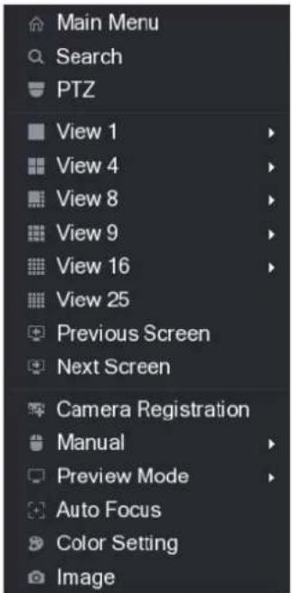
Shortcut Menu
You can quickly access some function interfaces such as main menu, record search, PTZ setting, color setting and select the view split mode.
Right-click on the live view screen, the shortcut menu is displayed.
After you access any interface through shortcut menu, you can return to the previous screen by right-clicking on the current screen.
text_image
Main Menu Search PTZ View 1 View 4 View 8 View 9 View 16 View 25 Previous Screen Next Screen Camera Registration Manual Preview Mode Auto Focus Color Setting Image| Function | Description |
| Main Menu | Open Main Menu interface. |
| Search | Open the PLAYBACK interface where you can search and play back record files. |
| PTZ | Open the PTZ interface. |
| View Layout | Configure the live view screen as a single-channel layout or multi-channel layout. |
| Previous Screen | Click Previous Screen to go to the previous screen. For example, if you are using 4-split mode, the first screen is displaying the channel 1-4, click Next screen, you can view channel 5-8. |
| Next Screen | |
| Camera Registration | Open the CAMERA REGISTRATION interface." |
| Manual | Select Record, you can configure the recording mode as Auto or Manual, or stop the recording. You can also enable or disable snapshot functionSelect Alarm Out, you can configure alarm output settings. |
| Preview Mode | Select General, the layout of live view screen is as default.Select Show Face List, the detected face snapshots are displayed in the bottom of the live view screen. |
| Auto Focus | Point to the channel window and right-click on it to open the shortcut menu, and then click Auto Focus.NOTENot all cameras support this function. |
| Color Setting | Open the COLOR interface where you can adjust the video image color. |
| Image | Click to modify the camera properties. |
Color Setting
You can adjust the video image color effect such as sharpness, brightness, and contrast. The parameters are different according to the connected camera type. Take analog channel as an example.
In the live view screen, right-click on the analog channel to see the shortcut menu, and then select Color Setting, the COLOR interface is displayed.

text_image
COLOR Period Period 1 Effective Time 00:00 - 24:00 Saturation + 50 Brightness + 50 Contrast + 50 Hue + 50 Sharpness + 1 Color Mode Standard EQ + 0 Position + 16 Customized Default Apply Back| Parameter | Description |
| Period | Divide 24 hours into two periods and configure the corresponding color settings. |
| Effective Time | Enable the function and then set the effective time for each period. |
| Sharpness | Adjust the sharpness of image edge. The bigger the value is, the more obvious the image edge, and the noise is also greater.The value ranges from 1 to 15. The default value is 1. |
| Hue | Adjust the hue of image. The value ranges from 0 to 100. The default value is 50. |
| Brightness | Adjust the image brightness. The value ranges from 0 to 100. The default value is 50.The bigger the value is, the brighter the image will become. You can adjust this value when the image as a whole looks dark or bright. However, the image is likely to become dim if the value is too big.The recommended range is between 40 and 60. |
| Contrast | Adjust the image contrast. The bigger the value is, the more obvious the contrast between the light area and dark area will become. You can adjust this value when the contrast is not obvious. However, if the value is too big, the dark area is likely to become darker and the light area over exposed. If the value is too small, the image is likely to become dim.The value ranges from 0 to 100. The default value is 50. The recommended range is between 40 and 60. |
| Saturation | Adjust the color shades. The bigger the value, the lighter the color will become. This value does not influence the general image lightness.The value ranges from 0 to 100. The default value is 50. The recommended range is between 40 and 60. |
| Color Mode | In the Color Mode list, you can select Standard, Soft, Bright, Colorful, Bank, Customized 1, Customized 2, Customized 3, and Customized 4.The sharpness, hue, brightness, contrast and saturation will adjust automatically according to the selected color mode. |
| EQ | Enhance the image effect. Adjust the effect value.Click , image is adjusted to the optimized effect automatically.Click , the current effect setting will be locked.NOTEOnly HD analog channel supports this function. |
| Position | Adjust the display position of the image in the channel window. The value indicates pixel. The default value is 16.NOTEThis function is only supported by analog channel. |
| Customized | You can customize four color modes.1. Click Customized. The Customized Color interface is displayed.2. In the Color Mode list, select Customized 1, for example. Then configure the settings for sharpness, hue, brightness, contrast and saturation. If you select All, the configuration will applies to all four customized color modes.3. Click OK.4. On the COLOR interface, in the Color Mode list, you can select the customized color mode. |
Live View Display
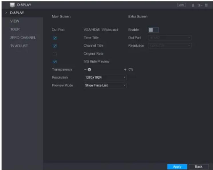
Configuring Display Settings
You can configure the display effect such as displaying time title and channel title, adjusting image transparency, and selecting the resolution.
Step 1 Select Main Menu > DISPLAY > Display.
The DISPLAY interface is displayed.
text_image
DISPLAY DISPLAY VIEW TOUR ZERO-CHANNEL TV ADJUST Main Screen Extra Screen Cut Port VGA/HDMI 1/Video out Enable ✓ Time Title Out Port HIM2 ✓ Channel Title Resolution 1.280x7.48 ✓ Original Rate ✓ IVS Rule Preview Transparency - + 0% Resolution 1280x1024 Preview Mode Show Face List Apply BackStep 2 Configure the settings for the display parameters.
| Parameter | Description | |
| Out Port | Indicates the main screen port. | |
| Main Screen | Time Title | Select the Time Title check box, the current system time displays in each channel window in live view screen. To hide the time, clear the check box. |
| Channel Title | Select the Channel Title check box, the channel name, channel number and recording status display in each channel window in live view screen. To hide the time, clear the check box. | |
| Original Rate | Select the Original Rate check box, the video image displays in its actual size in the channel window. | |
| IVS Rule Preview | Select the IVS Rule Preview check box to enable IVS rule preview function. | |
| Transparency | Configure the transparency of the graphical user interface (GUI). The higher the value, the more transparent the GUI becomes. | |
| Resolution | Select resolution for the video. The default resolution for VGA port and HDMI port is 1280×1024. NOTE Some of the resolution options might not be supported on the HDMI port. | |
| Preview Mode | General: No information is displayed on the channel window.Show Face List: Displays the detected face snapshots taken as a result of face detection on the bottom of the live view screen. NOTE Not all models support this function. | |
| Extra Screen | Enable | Enable extra screen function. After this function is enabled, you can select which port as extra screen port, and the other port automatically becomes the main screen port. |
| Out Port | Select the VGA port or HDMI port as the port connected by a secondary monitor. For example, if you select HDMI port as the extra screen port, the VGA port automatically becomes the main screen port. | |
| Resolution | Select resolution for the video. The default resolution for VGA port and HDMI port is 1280×720. NOTE Some of the resolution options might not be supported on the HDMI port. | |
| NOTEThe main menu does not display on the extra screen.If you do not enable the extra screen function, both the VGA port and HDMI port display the same image. | ||
Configuring Viewing Layout
You can configure the view layout in the live view screen.
Step 1 Select Main Menu > DISPLAY > VIEW.
The View Setting interface is displayed.

text_image
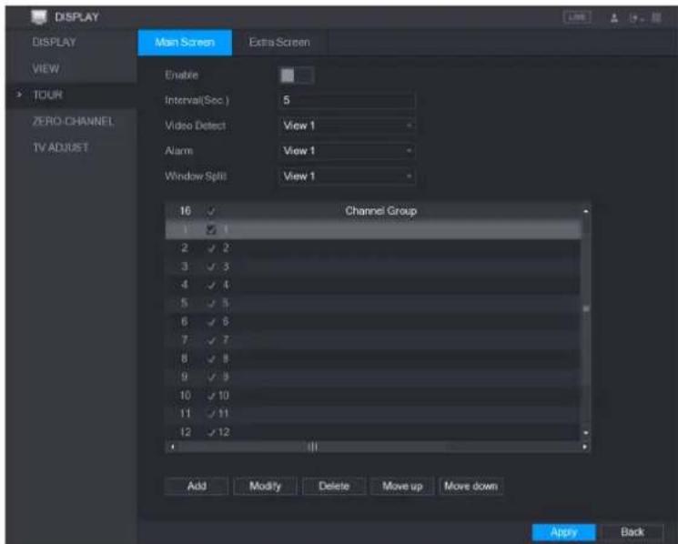
DISPLAY DISPLAY VIEW TOUR ZERO CHANNEL TV ADJUST View Setting 1 2 3 4 5 6 7 8 9 10 11 12 13 14 15 16 Apply BackStep 2 Configure the view layout by clicking the layout buttons on the bottom.
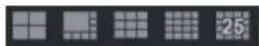
For example, click

and select 9-16, the view layout changes immediately.
text_image
DISPLAY DISPLAY VIEW TOUR ZERO CHANNEL TV ADJUST View Setting 9 10 11 12 16 15 14 13 Apply BackStep 3 Adjust the position of channels if needed.
In the channel list, for example, in the channel 9 list, you can select 10, and then the channel 9 and channel 10 exchange positions.
Step 4 Click Apply to complete the settings.
The live view screen displays the same layout as configured in this section.
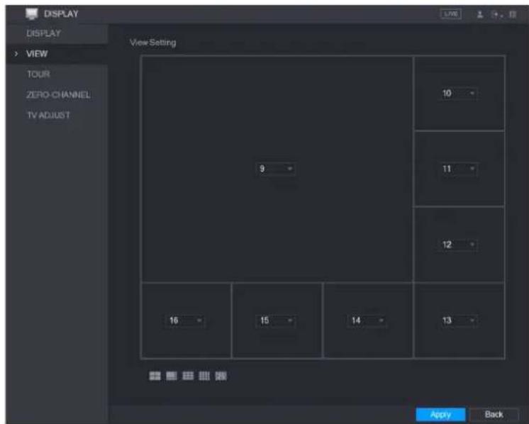
Configuring Zero-Channel Settings
You can view several video sources on one channel on the web end.
Step 1 Select Main Menu > DISPLAY > ZERO-CHANNEL.
The ZERO-CHANNEL interface is displayed.
text_image
DISPLAY DISPLAY VIEW TOUR ZERO CHANNEL TV ADJUST Enable Compression H.264 Resolution 704*576(D1) Frame Rate(FPS) 25 Bit Rate(Kb/S) 1024 Apply BackStep 2 Configure the settings for the zero-channel parameters.
| Parameter | Description |
| Enable | Enable zero-channel function. |
| Compression | In the Compression list, select the video compression standard according to the device capability. The default is H.264. |
| Resolution | In the Resolution list, select the video resolution. The default is 704×576 (D1). |
| Frame Rate (FPS) | Select a value between 1 and 25 for PAL standard, and between 1 and 30 for NTSC standard. The actual arrange is decided and selected dependent on the Device capability. |
| Bit Rate (Kb/S) | The default value is 1024Kb/S. The actual arrange is decided and selected dependent on the Device capability and frame rate. |
Step 3 Click Apply to save the settings.
In the live interface on the web, click

multi-channel modes, and then you can view the local video image.
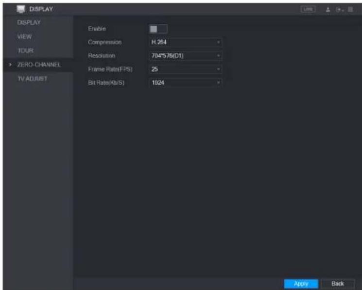
Configuring Tour Settings
You can configure a tour of selected channels to repeat playing videos. The videos display in turn according to the channel group configured in tour settings. The system is playing one channel group for a certain period and then automatically changes to the next channel group.
Step 1 Select Main Menu > DISPLAY > TOUR.
The TOUR interface is displayed. There are Main Screen tab and Extra Screen tab.
text_image
DISPLAY DISPLAY VIEW TOUR ZERO CHANNEL TV ADJUST Main Screen Extra Screen Enable Interval(Sec) 5 Video Detect View 1 Alarm View 1 Window Split View 1 16 Channel Group 1 2 3 4 5 6 7 8 9 10 11 12 Add Modify Delete Move up Move down Apply Back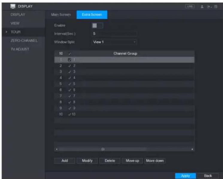
text_image
DISPLAY DISPLAY VIEW TOUR ZERO CHANNEL TV ADJUST Main Screen Extra Screen Enable Interval(Sec.) 5 Window Split View 1 10 Channel Group 1 2 3 4 5 6 7 8 9 10 Add Modify Delete Move up Move down Apply BackStep 2 Configure the settings for the tour parameters for both Main Screen and Extra Screen.
| Parameter | Description |
| Enable | Enable tour function. |
| Interval (Sec.) | Enter the amount of time that you want each channel group displays on the screen. The value ranges from 5 seconds to 120 seconds, and the default value is 5 seconds. |
| Video Detect, Alarm | Select the View 1 or View 8 for Motion Detect tour and Alarm Tour (system alarm events). |
| Window Split | In the Window Split list, select View 1, View 4, View 8, or other modes that are supported by the Device. |
| Channel Group | Display all channel groups under the current Window Split setting.Add a channel group: Click Add, in the pop-up Add Group channel, select the channels to form a group, and then click Save.Delete a channel group: Select the check box of any channel group, and then click Delete.Edit a channel group: Select the check box of any channel group and then click Modify, or double-click on the group. The Modify Channel Group dialog box is displayed. You can regroup the channels.Click Move up or Move down to adjust the position of channel group. |
Step 3 Click Apply to save the settings.
TIPS
- On the top right of the live view screen, use the left mouse button or press Shift
to switch between (image switching is allowed) and (image switching is not allowed) to turn on/off the tour function. - On the navigation bar, click to enable the tour and click to disable it.
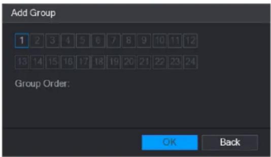
Adding a Channel Group
Step 1 Click Add.
The Add Group interface is displayed.
text_image
Add Group 1 2 3 4 5 6 7 8 9 10 11 12 13 14 15 16 17 18 19 20 21 22 23 24 Group Order: OK BackStep 2 Select the channels that you want to group for tour.

NOTE
If you want to select more than one channel, in the Window Split list, do not select
View 1.

text_image
Add Group 1 2 3 4 5 6 7 8 9 10 11 12 13 14 15 16 17 18 19 20 21 22 23 24 Group Order: 5,6,7,8 OK BackStep 3 Click OK to complete the settings.
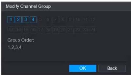
Modifying a Channel Group
Double-click on a channel group, the Modify Channel Group interface is displayed.
You can modify channel group and click OK to complete the settings.
text_image
Modify Channel Group 1 2 3 4 5 6 7 8 9 10 11 12 13 14 15 16 17 18 19 20 21 22 23 24 Group Order: 1,2,3,4 OK BackEntering Main Menu
Right-click on the live view screen, the shortcut menu is displayed, Click Main Menu and then login the system. The Main Menu is displayed.
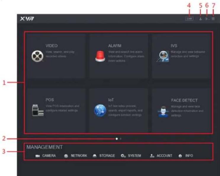
text_image
XVR 1 VIDEO View search, and play recorded videos ALARM View and search live audio information. Configure alarm event actions IVS Manage and view between detection and settings POS View POS information and configure related settings IoT Ist for video presence, search, export reports, and configure function settings FACE DETECT Manage and view face detection information and settings. 2 3 MANAGEMENT CAMERA NETWORK STORAGE SYSTEM ACCOUNT INFO| No. | Icon | Description |
| 1 | Function tiles | Includes eight function tiles:VIDEO, ALARM, IVS, POS, IoT, AI, BACKUP, DISPLAY, and AUDIO. Click each tile to open the configuration interface of the tile.VIDEO: Search for and play back the recorded video saved on the Device.ALARM: Search for alarm information and configure alarm event actions.IVS: Configure the behavior detections by drawing rules for detecting tripwire, intrusion, abandoned objects, and missing objects.BACKUP: Search and back up the video files to the local PC or external storage device such as USB storage device.DISPLAY: Configure the display effect such as displaying content, image transparency, and resolution, and enable the zero-channel function.AUDIO: Manage audio files and configure the playing schedule. The audio file can be played in response to an alarm event if the voice prompts function is enabled. |
| 2 | Switch icon | indicates the current page of main menu. Click switch to the next page. |
| 3 | Configura tion menu | Includes six configurations through which you can configure camera settings, network settings, storage settings, system settings, account settings, and view information. |
| 4 | Live | Click to go to the live view screen. |
| 5 | [42W6] | When you point to, the current user account is displayed. |
| 6 | [40XY] | Click, select Logout, Reboot, or Shutdown according to your actual situation. |
| 7 | [47Z7] | Displays Cell Phone Client and Device SN QR Code.Cell Phone Client: Use your mobile phone to scan the QR code to add the device into the Cell Phone Client, and then you can start accessing the Device from your cell phone.Device SN: Obtain the Device SN by scanning the QR code. Go to the P2P management platform and add the Device SN into the platform. Then you can access and manage the device in the WAN. |
Controlling PTZ Cameras
PTZ is a mechanical platform that carries a camera and a protective cover and performs overall control remotely. A PTZ can move in both horizontal and vertical direction to provide all-around view to the camera.
NOTE
Before operating PTZ, please assure the network connection between PTZ and the Device.
Configuring PTZ Connection Settings
You need to configure the PTZ connection settings before use.
- Local connection: RS485 Port for connecting Speed Dome or coaxial cable for connecting coaxial camera.
• Remote connection: local area network.
Step 1 Select Main Menu > CAMERA > PTZ.
The PTZ interface is displayed.

text_image
CAMERA IMAGE ENCODE OVERLAY PTZ CHANNEL TYPE: REGISTRATION COAXIAL UPGRADE Channel 1 Speed 5 Zoom + Focus + Bits + PTZ Type Control Mode HDCVI Protocol HDCVI3.0 Address 1 Baudate 9600 Data Bits 8 Stop Bits 1 Parity None Copy Apply CancelStep 2 Configure the settings for the PTZ connection parameters.
| Parameter | Description |
| Channel | In the Channel list, select the channel that you want to connect the PTZ camera to. |
| PTZ Type | Local: Connect through RS485 port or coaxial cable.Remote: Connect through network by adding IP address of PTZ camera to the Device. |
| Control Mode | In the Control Mode list, select Serial or HDCVI. For HDCVI series product, please select HDCVI. The control signal is sent to the PTZ through the coaxial cable. For the serial mode, the control signal is sent to the PTZ through the RS485 port. |
| Protocol | In the Protocol list, select the protocol for the PTZ camera, for example, select HDCVI3.0. |
| Address | In the Address box, enter the address for PTZ camera. The default is 1.NOTEThe entered address must be the same with the address configured on the PTZ camera; otherwise the PTZ camera cannot be controlled from the Device. |
| Baudrate | In the Baudrate list, select the baudrate for the PTZ camera. The default is 9600. |
| Data Bits | The default is 8. |
| Stop Bits | The default is 1. |
| Parity | The default is NONE. |
Step 3 Click Apply to save the settings.

Click Copy to copy the settings to other channels.
Working with PTZ Control Panel
PTZ control panel performs the operations such as directing camera in eight directions, adjusting zoom, focus and iris settings, and quick positioning.
Basic PTZ Control Panel
Right-click on the live view screen and then select PTZ. The PTZ control panel is displayed.

text_image
Speed 5 - Zoom + - Focus + - Iris +
NOTE
The functions with buttons in gray are not supported by the system.
| Parameter | Description |
| Speed | Controls the movement speed. The bigger the value is, the faster the movement will be. |
| Zoom | Wide angle.Long shot. |
| Focus | Zoom in.Zoom out. |
| Iris | Small.Large. |
| PTZ movement | Supports eight directions. |
| [DSXW] | Fast positioning button.Positioning: Click to enter the fast positioning screen, and then click anywhere on the live view screen, the PTZ will turn to this point and move it to the middle of the screen.Zooming: On the fast positioning screen, drag to draw a square on the view. The square supports zooming.Dragging upward is to zoom out, and dragging downward is to zoom in.The smaller the square, the larger the zoom effect.NOTENot all models support this function and can only be controlled through mouse operations. |
| [K06T] | Click [ZX44] can control the four directions (left, right, up, and down)PTZ movement through mouse operation. |
| [H073] | Click  to open the expanded PTZ control panel. to open the expanded PTZ control panel. |
Configuring Camera Settings
Configuring Image Settings
You can configure the image settings such as saturation, contrast, brightness, sharpness for each connected camera.
Step 1 Select Main Menu > CAMERA > IMAGE.
The IMAGE interface is displayed.
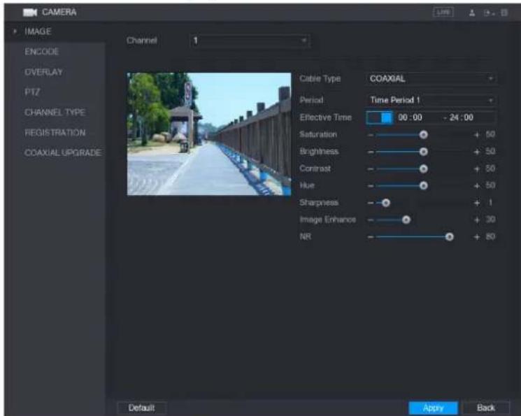
text_image
CAMERA IMAGE ENCODE OVERLAY PTZ CHANNEL TYPE REGISTRATION COAXIAL UPGRADE Channel 1 Cable Type COAXIAL Period Time Period 1 Effective Time 00:00 - 24:00 Saturation + 50 Brightness + 50 Contrast + 50 Hue + 50 Sharpness + 1 Image Enhance + 30 NR + 80 Default Apply BackStep 2 Configure the settings for the image parameters.
On the digital channel interface, click More Setting to display more parameters.
| Parameter | Description |
| Channel | In the Channel list, select the channel that you want to configure. |
| Cable Type | In the Cable Type list, select the cable type that the camera uses. |
| Period | In the Period list, select a time period for the image settings. The image settings will be only used during the selected period. |
| Effective Time | Enable the effective function.In the Effective Time box, enter the start time and end time for the period you selected. |
| Saturation | Adjusts the color shades. The bigger the value, the lighter the color will become. This value does not influence the general image lightness.The value ranges from 0 to 100. The default value is 50. The recommended range is between 40 and 60. |
| Contrast | Adjusts the image contrast. The bigger the value is, the more obvious the contrast between the light area and dark area will become. You can adjust this value when the contrast is not obvious. However, if the value is too big, the dark area is likely to become darker and the light area over exposed. If the value is too small, the image is likely to become dim.The value ranges from 0 to 100. The default value is 50. The recommended range is between 40 and 60. |
| Brightness | Adjusts the image brightness. The bigger the value is, the brighter the image will become. You can adjust this value when the image as a whole looks dark or bright. However, the image is likely to become dim if the value is too big.The value ranges from 0 to 100. The default value is 50. The recommended range is between 40 and 60. |
| Hue | Adjusts the hue of image. The value ranges from 0 to 100. The default value is 50. |
| Sharpness | Adjusts the sharpness of image edge. The bigger the value is, the more obvious the image edge, and the noise is also greater.The value ranges from 1 to 15. The default value is 1. |
| Image Enhance | Adjusts the image definition. The bigger the value is, the clearer the image will become, but there will be more noises. |
| NR | Reduces the noises from image. The bigger the value is, the better the image will become. |
| Config File | In the Config File list, select Day, Night, Normal, or Switch By Period. The system configures the parameters correspondingly.Day: Apply the configuration during daytime.Night: Apply the configuration during nighttime.Normal: Apply the configuration during day and night.Switch by Period: If you select this option, you need to configure the sunrise time and sunset time where you are located. |
| Mirror | Enable the function, the left and right side of the video image will be switched. It is disabled by default. |
| 3D Denoise | This function specially applies to the image which frame rate is configured as 2 at least. It reduces the noises by making use of the information between two frames. The bigger the value is, the better the effect. |
Commented [c1]:
| Parameter | Description |
| Flip | In the Flip list, you can select 180^ to change the video image display.By default, the setting is No Flip. |
| Light | In the Light list, select Close or Enable to use the backlight compensation or not. |
| Scene Mode | Configure the white balance to adjust the general hue of the image.The default setting is Auto.Auto: Automatically apply white balance to different colors to make the image color display normally.Sunny: Apply the threshold value to sunny environment.Night: Apply the threshold value to night.Customized: Manually adjust the Red Gain and Blue Gain values. |
| Day & Night | Configure the color and black&white mode of the image. This setting is not affected by the configuration files. The default setting is Auto.Color: The camera outputs color image only.Auto: Depends on the camera, such as overall brightness and whether there is an IR light, either color image or black&white image is output.B/W: The camera outputs Black and white image only.By Time: The camera outputs image according to the configure the sunrise time and sunset time. |
Step 3 Click Apply to complete the settings.
Commented [c2]:
Configuring Encode Settings
Step 1 Select Main Menu > CAMERA > ENCODE > Encode.
The Encode interface is displayed.

text_image
CAMERA IMAGE Encode Snapshot ENCODE CHANNEL 1 OVERLAY PTZ CHANNEL TYPE REGISTRATION COAXIAL UPGRADE Main Stream Smart Codes Type Regular Compression H.265 Resolution 1920x1080(1080P) Frame Rate(FPS) 15 Bit Rate Type CBR Frequency 1 Frame Interval 1 S Bit Rate(Kb/S) 2048 More Setting Sub Stream Video Type Sub Stream1 Compression H.265 Resolution 352*240(CIF) Frame Rate(FPS) 15 Bit Rate Type CBR Frequency 1 Frame Interval 1 S Bit Rate(Kb/S) 640 More Setting Default Copy Apply BackCommented [c3]:
Step 2 Configure the settings for the main/sub streams parameters.
| Parameter | Description |
| Channel | In the Channel list, select the channel that you want to configure the settings for. |
| Smart Codec | Enable the smart codec function. This function can reduce the video bit stream for non-important recorded video to maximize the storage space. |
| Type | Main Stream: In the Type list, select General, MD (Motion Detect), or Alarm.Sub Stream: This setting is not configurable. |
| Compression | In the Compression list, select the encode mode.H.265: Main profile encoding.H.264H: High profile encoding. Low bit stream with high definition. This setting is recommended.H.264: General profile encoding.H.264B: Baseline profile encoding. This setting requires higher bit stream compared with other settings for the same definition. |
| Resolution | In the Resolution list, select resolution for the video.The maximum video resolution might be different dependent on your device model. |
Commented [c4]:
| Parameter | Description |
| Frame Rate (FPS) | Configure the frames per second for the video. The higher the value, the clearer and smoother the image will become. Frame rate changes along with the resolution.Generally, in PAL format, you can select the value from 1 through 25; in NTSC format, you can select the value from 1 through 30.However, the specific range of frame rate that you can select depends on the capability of the Device. |
| Quality | This function is available if you select VBR in the Bit Rate List.The higher the value, the better the image will become. |
| I Frame Interval | The interval between two reference frames. |
| Bit Rate (Kb/S) | In the Bit Rate list, select a value or enter a customized value to change the image quality. The bigger the value is, the better the image will become. |
| Video | Enable the function for sub stream. |
| Audio Encode | Click More Setting, the More Setting interface is displayed.Audio Encode: This function is enabled by default for main stream. You need to manually enable it for sub stream 1. Once this function is enabled, the recorded video file is composite audio and video stream.Audio Source: In the Audio Source list, you can select LOCAL and HDCVI.LOCAL: The audio signal is input from Audio input port.HDCVI: The audio signal is input from HDCVI camera.Audio Format: In the Audio Format list, select a format that you need. |
| Audio Source | |
| Audio Format |
Step 3 Click Apply to complete the settings.

Click Copy to copy the settings to other channels.
Configuring Snapshot Settings
Step 1 Select Main Menu > CAMERA > ENCODE > Snapshot.
The Snapshot interface is displayed.

text_image
CAMERA IMAGE ENCODE OVERLAY PTZ CHANNEL TYPE REGISTRATION COAXIAL UPGRADE Encode Snapshot Manual Snap 1 /Time Channel 1 Mode General Image Size 352*288(CIF) Image Quality 4 Interval 1 Second Default Copy Apply BackStep 2 Configure the settings for the snapshot parameters.
| Parameter | Description |
| Manual Snap | In the Manual Snap list, select how many snapshots you want to take each time. |
| Channel | In the Channel list, select the channel that you want to configure the settings for. |
| Mode | In the Mode list, you can select Human Face, Event, or General as the event type for which you want to take a snapshot. |
| Image Size | In the Image Size list, select a value for the image. |
| Image Quality | Configures the image quality by 6 levels. The higher the level, the better the image will become. |
| Interval | Configures or customizes the snapshot frequency. |
Step 3 Click Apply to complete the settings.
NOTE
Click Copy to copy the settings to other channels.
Configuring Overlay Settings
You can configure to display system time and channel name on each channel window in the live view screen.
Step 1 Select Main Menu > CAMERA > OVERLAY > Overlay.
The Overlay interface is displayed.

text_image
CAMERA IMAGE ENCODE OVERLAY PTZ CHANNEL TYPE REGISTRATION COAXIAL UPGRADE Overlay Cover-Area Channel 1 2017-11-03 23:55:06 Time Display YYYY... Channel Title CAM 1 CAM 1 Default Copy Apply BackStep 2 Configure the settings for the text overlay parameters.
| Parameter | Description |
| Channel | In the Channel list, select the channel that you want to configure the settings for. |
| Time Display | Select the Time Display check box to display the system time on each channel window in the live view screen.In the Time Display list, select time display style. |
| Channel Title | Select the Channel Title check box to display the channel name on each channel window in the live view screen.In the Channel Title box, enter the name for the selected channel. |
Step 3 Click Apply to complete the settings.
NOTE
Click Copy to copy the settings to other channels.
Configuring Covered Area Settings
Step 1 Select Main Menu > CAMERA > OVERLAY > Cover-Area.
The Cover-Area interface is displayed.

text_image
CAMERA IMAGE ENCODE OVERLAY PTZ CHANNEL TYPE REGISTRATION COAXIAL UPGRADE Overlay Cover Area Channel 1 Preview Record Default Apply BackStep 2 Configure the settings for the covered area parameters.
| Parameter | Description |
| Channel | In the Channel list, select the channel that you want to configure the settings for. |
| Preview | ● Preview: Select the Preview check box to apply the configured covered block to the selected channel window in the live view screen.● Record: Select the Record check box to apply the configured covered block to the selected channel window during recording. To configure covering block, do the following:1. Select the Preview check box or the Record check box, or select the both. The "1, 2, 3, 4" buttons are activated.2. Click the buttons to select blocks.3. A triangle solid black block is displayed. You can drag the block to the area that you want to cover and adjust the size of the block.4. You can configure total 4 covered blocks. |
| Record |
Step 3 Click Apply to complete the settings.
Configuring Channel Type
You can configure the channel type as Analog or IP channel.
Step 1 Select Main Menu > CAMERA > CHANNEL TYPE.
The CHANNEL TYPE interface is displayed.
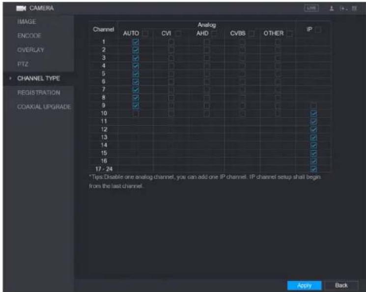
text_image
CAMERA IMAGE ENCODE OVERLAY PTZ CHANNEL TYPE REGISTRATION COAXIAL UPGRADE Channel Analog AUTO CVI AHD CVBS OTHER IP 1 2 3 4 5 6 7 8 9 10 11 12 13 14 15 16 17 - 24 *Tips:Disable one analog channel, you can add one IP channel. IP channel setup shall begin from the last channel. Apply BackStep 2 Configure the channels.
- Analog Channel: Select the transmission medium such as CVI, CVBS, and then follow the onscreen instructions to complete the settings.
- IP Channel: Select a channel for IP camera from the last channel number, for example, in Error! Reference source not found., select from the 17–24 check box. Then follow the onscreen instructions to complete the settings.
NOTE
- The 17–24 channels are only for IP camera and the range changes dependent on the model you purchased.
- The channel selection for analog camera or IP camera are in sequence, for example, if you want to select channels for IP camera, you need to select the 17–24 check box first, and then you cannot jump to select the channel 15 directly until you have selected the channel 16.
Step 3 Click Apply and follow the onscreen instructions to complete the settings.
Upgrading Coaxial Camera
Step 1 Select Main Menu > CAMERA > COAXIAL UPGRADE.
The COAXIAL UPGRADE interface is displayed.
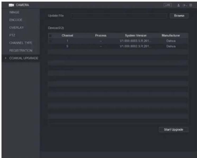
text_image
CAMERA IMAGE ENCODE OVERLAY PTZ CHANNEL TYPE REGISTRATION COAXIAL UPGRADE Update File Browse Device(0/2) Channel Process System Version Manufacturer 1 - V1.000.6003.3.R.201... Dahua 5 - V1.000.6002.3.R.201... Dahua Start UpgradeStep 2 Click Browse.
The Browse interface is displayed.
Step 3 Select the upgrade file and click OK.
The COAXIAL UPGRADE interface is displayed.

NOTE
You need to insert the USB storage device that contains the upgrading files.
Step 4 Select the check box of the channel that you want to upgrade.
Step 5 Click Start Upgrade.
If the upgrading is successful, the system pops up a message indicating the upgrading is completed. If the upgrading is failed, please check if the Device
Configuring Remote Devices
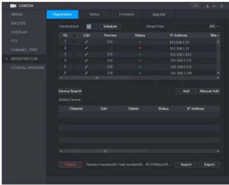
Adding Remote Devices

NOTE
This function is available after you have configured the channel type as IP channel as described in previous section.
You can add remote devices by adding the IP address.
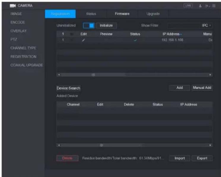
Select Main Menu > CAMERA > REGISTRATION > Registration, the Registration interface is displayed.

text_image
CAMERA IMAGE ENCODE OVERLAY PTZ CHANNEL TYPE REGISTRATION COAXIAL UPGRADE Registration Status Firmware Upgrade Uninstalled Initialize Show Filter IPC 0 Edit Preview Status IP Address Manu Device Search Add Manual Add Added Device Channel Edit Delete Status IP Address Residue bandwidth/Total bandwidth: 49.50Mbps/49... Import Export| Parameter | Description |
| Uninitialized | Enable theUninitializedfunction, the uninitialized devices out of the searched devices are displayed in the searched device list. |
| Initialize | Select the uninitialized device from the uninitialized device list, and the clickInitializeto start initializing device. |
| Show Filter | In theShow Filterlist, select the remote device type that you want to display in the searched device list.None: Display all types of devices.IPC: Display the front-end devices.DVR: Display all storage devices such as NVR, DVR and HCVR.OTHER: Display the devices that do not belong to IPC or DVRType. |
| Searched Device List | Displays the searched devices. You can view the device information such as status, IP address. |
| Device Search | ClickDevice Search, the searched devices display in the searched device list.To adjust the display sequence, in the title line, you can click the IP address, Manufacturer, Type, MAC Address, Port, or Device Name text. For example, click the IP address text, the sequence iconIP Addressis displayed.NOTE"" is displayed next to the added device. |
| Add | In the Searched Device List area, select the device that you want to add. |
Commented [c5]:
| Parameter | Description |
| Manual Add | Add the device by manually configuring settings such as IP address, channel selection. |
| Added Device List | Displays the added devices. You can edit and delete the device, and view the device information. |
| Delete | Select the check box of the added device, and then click Delete to delete the added device. |
| Import | Select the searched devices and then click Import to import the devices in batches. |
| Export | Select the added devices and then click Export. The exported devices information is saved into the USB storage device. |
Initializing Remote Devices
You can reset the password and IP address of the remote devices through initializing.
Step 1 Click Device Search.
The searched devices are displayed in the table.
text_image
CAMERA IMAGE ENCODE OVERLAY PTZ CHANNEL TYPE REGISTRATION COAXIAL UPGRADE Registration Status Firmware Upgrade Unrealized Initialize Show Filter IPC 50 Edit Preview Status IP Address Mar 1 ✓ 124 ✓ 192.168.1.10 2 ✓ ✓ ✓ 192.168.1.31 3 ✓ 124 ✓ 192.168.1.123 4 ✓ 124 ✓ 192.168.1.131 5 ✓ 124 ✓ 192.168.1.151 6 ✓ 124 ✓ 192.168.1.154 Device Search Add Manual Add Added Device Channel Edit Delete Status IP Address Residue bandwidth/Total bandwidth: 49.50Mbps/48... Import ExportStep 2 Enable the Initialized function.
The uninitialized devices are displayed.
text_image
CAMERA IMAGE ENCODE OVERLAY PTZ CHANNEL TYPE REGISTRATION COAXIAL UPGRADE Registration Status Firmware Upgrade Uninitialized Initialize Show Filter IPC 1 Edit Preview Status IP Address - Manu 1 192.168.1.106 De Device Search Add Manual Add Added Device Channel Edit Delete Status IP Address Delete Passive bandwidth Total bandwidth 61.50Mbps/61... Import ExportStep 3 Select the uninitialized device that you want to initialize.
Step 4 Click Initialize.
The Enter Password interface is displayed.
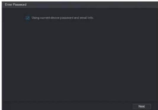
text_image
Enter Password ✓ Using current device password and email info. NextStep 5 Configure the password and email information.

If you select the Using current device password and email info check box, the remote device automatically uses the current password and email information, so you do not need to set the password and email address again and can go to Step 6.
1) Clear the Using current device password and email info check box. The password setting interface is displayed.
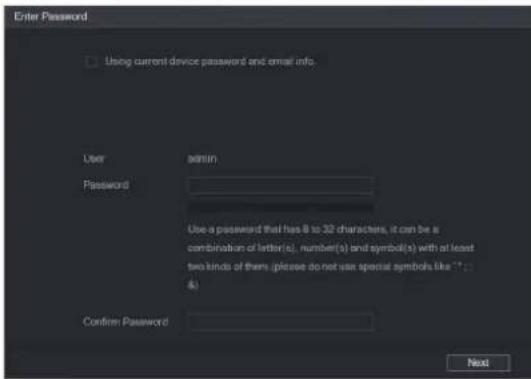
text_image
Enter Password Using current device password and email info. User Password Use a password that has 8 to 30 characters, it can be a combination of letter(s), number(s) and symbol(s) with at least two kinds of them (please do not use special symbols like ".." 4) Confirm Password Next2) Configure the settings for the password setting parameters.
| Parameter | Description |
| User | The default is admin. |
| Password | The new password can be set from 8 characters through 32 characters and contains at least two types from number, letter and special characters (excluding "", "", ";", ";" and "&").Please enter a strong password according to the password strength bar indication. |
| Confirm Password |
3) Click Next.
The Password Protection interface is displayed.
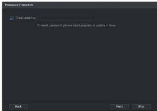
text_image
Password Protection Email Address To reset password, please input properly or update in time Back Next Skip4) Select the Email Address box and enter the email address that you want to reserve for password reset in the future.

If you do not want to set the reserved email address, click Skip.
Step 6 Click Next.
The NETWORK interface is displayed.

text_image
NETWORK Checked Device No.: 1 DHCP STATIC IP Address 192 . 168 . 1 . 108 Subnet Mask 255 . 255 . 255 . 0 Default Gateway 192 . 168 . 1 . 1 Incremental Value 1 1 IP Address 1 192.168.1.108 Back Next SkipStep 7 Configure the IP address.
- Select the DHCP check box, you do not need to enter the IP address information, because the system will allocate one IP address to the remote device.
- Select the STATIC check box, you need to enter the IP address, subnet mast, default gateway, and incremental value. The system will allocate the IP address to the remote devices by progressively increasing the last part of the IP address when initializing devices in batches.

NOTE
When configuring IP address for multiple remote devices which were not in the same network segment, these remote devices will belong to the same network segment after configuration.
Step 8 Click Next.
The initializing is started. After the process is completed,

text_image
Device Initialization Device Initialization Finished 1 IP Address Serial No. Results 1 192.168.1.108 000000000000000 Initialize:Succeed Modify IP:Succeed FinishedStep 9 Click Finished to complete the settings.
Adding Remote Devices Automatically
Step 1 On the Registration interface, click Device Search
The searched devices are displayed.

text_image
CAMERA IMAGE ENCODE OVERLAY PTZ CHANNEL TYPE REGISTRATION COAXIAL UPGRADE Registration Status Firmware Upgrade Unrealized Initialize Show Filter IPC 50 Edit Preview Status IP Address Mar 1 ✓ USB ✓ 192.168.1.19 2 ✓ ✓ ✓ ✓ 192.168.1.31 3 ✓ USB ✓ 192.168.1.123 4 ✓ USB ✓ 192.168.1.131 5 ✓ USB ✓ 192.168.1.151 6 ✓ USB ✓ 192.168.1.154 Device Search Add Manual Add Added Device Channel Edit Delete Status IP Address Delete Rescure bandwidth/Total bandwidth: 49.50Mbps/49.50Hz Import ExportStep 2 Select the check box of the device.
Step 3 Click Add.
The device is added into the Added Device area.

NOTE
- You can also double-click the device to add it into the Added Device area.
- You can add devices in batches.
Adding Remote Devices Manually
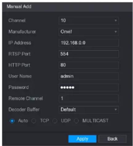
Step 1 On the Registration interface, click Manual Add.
The Manual Add interface is displayed.
text_image
Manual Add Channel 10 Manufacturer Onvif IP Address 192.168.0.0 RTSP Port 554 HTTP Port 80 User Name admin Password •••••• Remote Channel 1 Decoder Buffer Default Auto TCP UDP MULTICAST Apply BackStep 2 Configure the settings for the manual adding device parameters.
| Parameter | Description |
| Channel | In the Channel list, select the channel that you want use on the Device to connect the remote device. |
| Manufacturer | In the Manufacturer list, select the manufacturer of the remote device. |
| IP Address | In the IP Address box, enter the IP address of remote device. Ⓞ NOTEThe default is 192.168.0.0 which the system cannot connect to. |
| RTSP Port | The default value setting is 554. You can enter the value according to your actual situation. |
| HTTP Port | The default value setting is 80. You can enter the value according to your actual situation.If you enter other value, for example, 70, and then you should enter 70 after the IP address when logging in the Device by browser. |
| User Name | Enter the user name of the remote device. |
| Password | Enter the password of the user for the remote device |
| Remote Channel | Enter the remote channel number of the remote device that you want to add. |
| Decoder Buffer | In the Decoder Buffer list, select Default, Realtime, or Fluent. |
| Protocol Type | Select Auto, TCP, UDP, or MULTICAST. The default is TCP. |
Step 3 Click Apply to save the settings.

NOTE
- Only one device can be added manually at one time.
• indicates successful connection and indicates connection failed.
Modifying or Deleting Remote Devices
You can modify and delete the added devices.
- To modify the remote devices, do the following:
Step 1 Click or double-click a device.
The Edit interface is displayed.

text_image
Edit Channel 10 Manufacturer Onvif IP Address 192.168.1.123 RTSP Port 554 HTTP Port 80 User Name admin Password •••••• Remote Channel 1 Decoder Buffer Default Auto TCP UDP MULTICAST Copy OK BackStep 2 In the Channel list, select the channel that you want to modify settings for.
Step 3 Click OK to save the settings.

NOTE
Click Copy to copy the user name and password to other channels.
- To delete one or more added devices, do the following:
◇ Click to delete one device
Select the check box of the devices that you want to delete, and then click Delete.
Modifying IP Address
You can modify a single IP address or multiple IP addresses of remote devices at the one time.
- To modify a single IP address, do the following:
Step 1 In the Searched Device list area, click for the device that you want to modify IP.
The Modify IP interface is displayed.

text_image
Modify IP IP Address 192 , 168 , 3 , 133 Subnet Mask 255 , 255 , 0 , 0 Default Gateway 192 , 168 , 0 , 1 User Name admin Password Add OK BackStep 2 Configure the settings for IP address, subnet mask, default gateway, user name, and password.
Step 3 Enable the Add function to add the device into the Added Device area.
Step 4 Click OK to save the settings.
- To modify IP address in batches, do the following:
Step 1 In the Searched Device list area, select the devices that you want to modify IP address in batches.
Step 2 Click
The Modify IP interface is displayed.
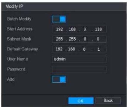
text_image
Modify IP Batch Modify Start Address 192 , 168 , 3 , 133 Subnet Mask 255 , 255 , 0 , 0 Default Gateway 192 , 168 , 0 , 1 User Name admin Password Add OK BackStep 3 Enable the Batch Modify function.
Step 4 Configure the settings for start IP address (the IP address is allocated in sequence), subnet mask, default gateway, user name, and password.
Step 5 Enable the Add function to add the devices into the Added Device area.
Step 6 Click Apply to save the settings.
Exporting IP Address
You can export the added IP address to the USB storage device.
NOTE
The exported information is saved in .csv file, which includes IP address, port number, channel number, manufacturer, user name, and password.
Step 1 Insert the USB storage device to the USB port of the Device.
Step 2 Click Export.
The Browse interface is displayed.

text_image
Browse Device Name sda5(USB DISK) Refresh Format Total Space 15.60 GB Free Space 15.60 GB Address / Name Size Type Delete IP Folder New Folder OK BackStep 3 Configure the save path.
Step 4 Click OK to save the settings.
A pop-up message indicating "Successfully exported" is displayed.
Step 5 Click OK.
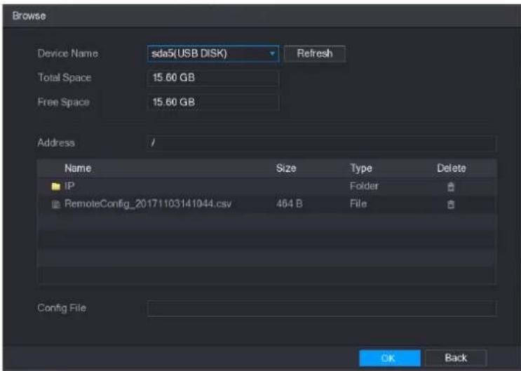
Importing IP Address
You can add remote devices by importing IP address information.
Step 1 Insert the USB storage device to the USB port of the Device.
Step 2 Click Import.
The Browse interface is displayed.
text_image
Browse Device Name sda5(USB DISK) Refresh Total Space 15.60 GB Free Space 15.60 GB Address / Name Size Type Delete IP Folder RemoteConfig_20171103141044.csv 464 B File Config File OK BackStep 3 Select the file that you want to import.
Step 4 Click OK to start importing.
After importing is completed, a pop-up message indicating "The import succeeded" is displayed.

NOTE
If the IP address that you want to import already exists in the Device, the system will pop up a message to ask you whether to overwrite the existing content.
- Click OK to replace the existing one.
- Click Cancel to add it as a separate device in the Added Device area.

CAUTION
- You can edit the exported .csv file and be cautious not to change the file format; otherwise the file cannot be imported as it will be judged as invalid.
- The language of .csv file must match the Device language.
• The import and export through customized protocol is not supported.
Managing Remote Devices
You can view the status of remote devices and upgrade.
Viewing Status
You can view the device information such as connection status, IP address, motion detection, video loss detection, camera name, and manufacturer.
Select Main Menu > CAMERA > REGISTRATION > Status, the Status interface is displayed.

text_image
CAMERA IMAGE ENCODE OVERLAY PTZ CHANNEL TYPE REGISTRATION COAXIAL UPGRADE Registration Status Firmware Upgrade Device Status Channel Status IP Address MD Video Loss Tempening 11 192.168.1.123 -- -- RefreshViewing Firmware Information
You can view the device firmware information such as channel number, IP address, manufacturer, system version, video input, audio input, and alarm in.
Select Main Menu > CAMERA > REGISTRATION > Firmware, the Firmware interface is displayed.

text_image
CAMERA IMAGE BRIDGE OVERLAY PTZ CHANNEL TYPE REGISTRATION COXIAL UPGRADE Registration Status Firmware Upgrade Channel IP Address Manufacturer Type System Version No 11 192.168.3.136 ISO-576... 2.480.0001.... 2.01505YA... RefreshUpgrading Remote Devices
Step 1 Select Main Menu > CAMERA > REGISTRATION > Upgrade.
The Upgrade interface is displayed.

text_image
CAMERA IMAGE ENCODE OBSYLAY PTZ CHANNEL TYPE REGISTRATION COAXIAL UPGRADE Registration Status Formware Upgrade Device Upgrade(0/1) Channel Status IP Address System Version Process Upgrade Port 11 192.368.1.223 To be upgraded Detect 27773 File Upgrade Manual Check Online UpgradeStep 2 Upgrade the device.
-
File Upgrade
1) Insert a USB storage device containing the upgrade files into the USB port of the Device.
2) Select the devices that you want to upgrade.
3) Click File upgrade. The File Upgrade interface is displayed.
4) Select the upgrading files and click Apply. -
Online Upgrade
1) Click Detect or select the check box the device that you want to upgrade and click Manual Check.
The system starts detecting if there is a new version on the online server.
2) Select the check box of all the devices that have new version.
3) Click Online Upgrade.
NOTE
- The system will pop up a message to indicate if the upgrading is successful.
- You can use the Type list to filter the devices so that you can find the devices quickly.
Configuring Record Settings
You can record video manually or automatically and configure the recording settings to main stream and sub stream respectively.
Enabling Record Control

CAUTION
- Manual recording operation requires the user have the permission to access STORAGE settings.
- Check to ensure the HDD installed in the Device has been formatted properly.
To enter the record control interface, do the following:
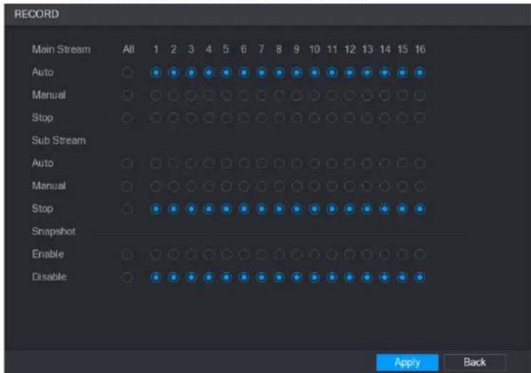
Step 1 Right-click on the live view screen, the shortcut menu is displayed. On the shortcut menu, select Manual > Record Control.

text_image
RECORD Main Stream All 1 2 3 4 5 6 7 8 9 10 11 12 13 14 15 16 Auto Manual Stop Sub Stream Auto Manual Stop Snapshot Enable Disable Apply BackStep 2 Configure the settings for the record control parameters.
| Parameter | Description |
| Channel | Displays all the analog channels and the connected digital channels. You can select a single channel or select All. |
| Record status | ● Auto: Automatically record according to the record type and recording time as configured in the recording schedule.● Manual: Keep general recording for 24 hours for the selected channel.● Stop: Do not record. |
| Snapshot status | Enable or disable the scheduled snapshot for the corresponding channels. |
Step 3 Click Apply.
Configuring Recorded Video Storage Schedule
You need to configure the storage schedule for the recorded video so that the recorded video can be saved.
Configuring Snapshot Settings
Configuring Snapshot Trigger
The snapshot is divided into scheduled snapshot, event triggered snapshot, and face detection triggered snapshot. When the both are enabled, the event triggered snapshot has the priority.
- If there is no alarm event, the system performs scheduled snapshot.
- If there is any alarm event, the system performs event triggered snapshot.
Configuring Scheduled Snapshot
Step 1 Right-click on the live view screen, the shortcut menu is displayed.
Step 2 On the shortcut menu, select Manual > Record Control.
The RECORD interface is displayed.
Step 3 In the Snapshot area, enable the snapshot for the channels if needed.
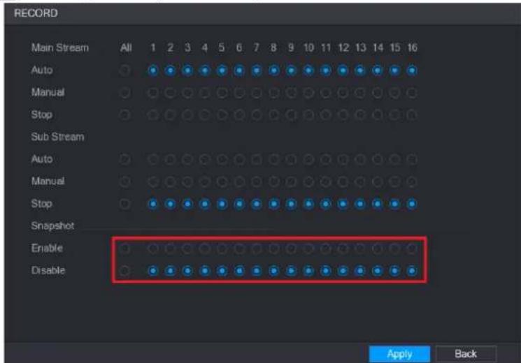
text_image
RECORD Main Stream All 1 2 3 4 5 6 7 8 9 10 11 12 13 14 15 16 Auto Manual Stop Sub Stream Auto Manual Stop Snapshot Enable Disable Apply BackStep 4 Select Main Menu > CAMERA > ENCODE > Snapshot.
The Snapshot interface is displayed.
Step 5 In the Mode list, select General, and then configure other parameters.
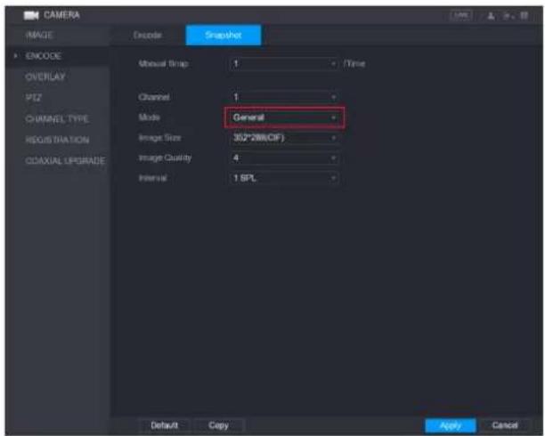
text_image
CAMERA IMAGE ENCODE OVERLAY PTZ CHANNEL TYPE REGISTRATION ODAXIAL UPGRADE Encoder Snapshot Manual Strip: 1 Time Channel: 1 Mode: General Image Size: 352*288(CIF) Image Quality: 4 Interval: 1 SPL Default Copy Apply CancelStep 6 Click Apply to save the settings.
- If you have configured the snapshot schedule, the configuration has been completed.
Configuring Event Triggered Snapshot
Step 1 Select Main Menu > CAMERA > ENCODE > Snapshot.
The Snapshot interface is displayed.
Step 2 In the Mode list, select Event, and then configure other parameters.
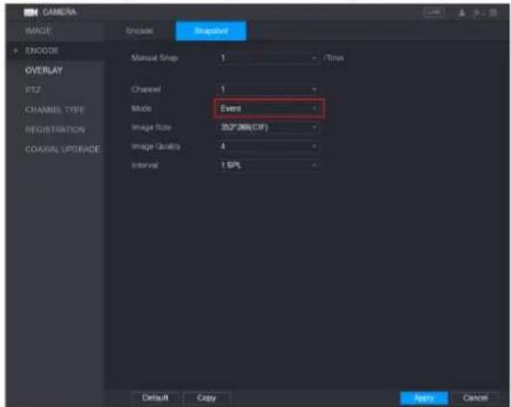
text_image
CAMERA IMAGE Encode Sigmafile ENCODE OVERLAY PTZ CHANNEL TYPE REGISTRATION COXIAL UPGRADE Manual Snap 1 Time Channel 1 Mode Event Image Size 302PDB(CIF) Image Capacity 4 Interval 1 SPL Default Copy Help CancelStep 1 Select Main Menu > ALARM > VIDEO DETECT, and select the event type to configure, for example, select the Motion Detect tab.
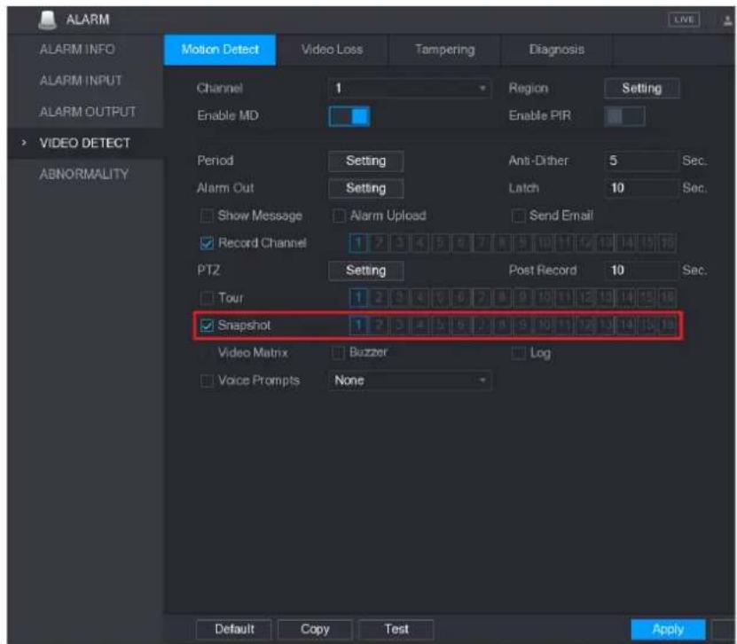
text_image
ALARM ALARM INFO ALARM INPUT ALARM OUTPUT Motion Detect Video Loss Tampering Diagnosis Channel 1 Region Setting Enable MD Enable PIR VIDEO DETECT ABNORMALITY Period Setting Anti-Dither 5 Sec. Alarm Out Setting Latch 10 Sec. Show Message Alarm Upload Send Email Record Channel 1 2 3 4 5 6 7 8 9 10 11 12 13 14 15 16 PTZ Setting Post Record 10 Sec. Tour 1 2 3 4 5 6 7 8 9 10 11 12 13 14 15 16 Snapshot 1 2 3 4 5 6 7 8 9 10 11 12 13 14 15 16 Video Matrix Buzzer Log Voice Prompts None Default Copy Test ApplyStep 2 Select the Snapshot check box and select the corresponding channel.
Step 3 Click Apply.
Configuring Face Detection Triggered Snapshot
Step 1 Select Main Menu > CAMERA > ENCODE > Snapshot.
The Snapshot interface is displayed.
Step 2 In the Mode list, select Human Face, and then configure other parameters.

text_image
CAMERA IMAGE Encode Snapshot ENCODE OVERLAY PTZ CHANNEL TYPE REGISTRATION COAXIAL UPGRADE Manual Snap 1 /Time Channel 1 Mode Human Face Image Size 1280*720(720P) Image Style 1 Default Apply CancelStep 3 Select Main Menu > FACE DETECT > PARAMETERS > Human Face.
The Human Face interface is displayed.

text_image
FACE DETECT SMART SEARCH Human Face PARAMETERS Channel 1 Target Filter Setting Enable Period Setting Alarm Out Setting Latch 10 Sec. Send Email Record Channel 1 Post Record 10 Sec. PTZ Setting Post Record 10 Sec. Snapshot 1 Buzzer Log Voice Prompts None Default Apply BackStep 4 Select the Snapshot check box and select the corresponding channel.
Step 5 Click Apply.
Configuring Snapshot Storage Schedule
You need to configure the storage schedule for the snapshot so that the snapshot can be saved.
Backing up Snapshots to FTP
Step 1 Select Main Menu > STORAGE > FTP.
The FTP interface is displayed.

text_image
STORAGE BASIC SCHEDULE HDD MANAGER ADVANCE QUOTA HDD DETECT REC ESTIMATE FTP Enable Host IP 0 0 0 0 Port 21 Anonymity User Name Password Remote Directory File Length(M) 0 Image Upload Interval(Sec.) 2 Channel 1 Week Day Wed Alarm Intel MD General Period 1 00:00 -24:00 Period 2 00:00 -24:00 Default Test Apply BackStep 2 Enable the FTP function and configure the parameters."
The snapshots will be uploaded to FTP for backup.
Playing Back Video
Enabling Record Control

CAUTION
- Manual recording operation requires the user have the permission to access STORAGE settings.
- Check to ensure the HDD installed in the Device has been formatted properly.
- Manual recording operation requires the user have the permission to access STORAGE settings.
- Check to ensure the HDD installed in the Device has been formatted properly.
To enter the record control interface, do the following:
Step 1 Right-click on the live view screen, the shortcut menu is displayed. On the shortcut menu, select Manual > Record Control.
text_image
RECORD Main Stream All 1 2 3 4 5 6 7 8 9 10 11 12 13 14 15 16 Auto Manual Stop Sub Stream Auto Manual Stop Snapshot Enable Disable Apply BackStep 2 Configure the settings for the record control parameters.
| Parameter | Description |
| Channel | Displays all the analog channels and the connected digital channels. You can select a single channel or select All. |
| Record status | ● Auto: Automatically record according to the record type and recording time as configured in the recording schedule.● Manual: Keep general recording for 24 hours for the selected channel.● Stop: Do not record. |
| Snapshot status | Enable or disable the scheduled snapshot for the corresponding channels. |
Instant Playback
You can use the instant playback function to play back the previous five minutes to sixty minutes of the recorded video in any channel.
Main Interface of Video Playback
You can search for and play back the recorded video saved on the Device.
Select Main Menu > VIDEO, the video search interface is displayed.
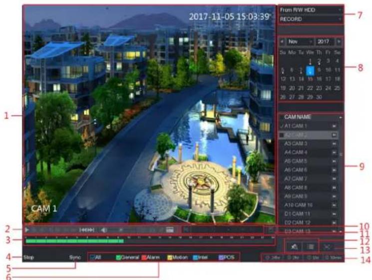
text_image
2017-11-05 15:03:39 From RW HDD RECORD New 2017 Su Mo Tu We Th Fr Se 8 12 13 14 15 16 17 18 19 20 21 22 23 24 25 20 27 28 29 30 CAM NAME A1 CAM 1 A2 CAM 2 A3 CAM 3 A4 CAM 4 A5 CAM 5 A6 CAM 6 A7 CAM 7 A8 CAM 8 A9 CAM 9 A10 CAM 10 D1 CAM 11 D2 CAM 12 D3 CAM 13 CAM 1 CAM 1 Stop Sync General Alarm Motion Intel SPOS 24hr 2hr 5hr 10ms 11 12 13 14| No. | Function | Description |
| 1 | Display Window | Display the searched recorded video or picture. It supports playing in single-channel, 4-channel and 9-channelNOTEWhen playing back in a single channel mode, hold down the left mouse button to select the area that you want to enlarge. The area is enlarged after the left mouse button is released. To exit the enlarged status, right-click on the image. |
| 2 | PlaybackControls Bar | Playback control buttons. |
| 3 | Time Bar | Display the type and time period of the current recorded video.In the 4-channel layout, there are four time bars are displayed; in the other view layouts, only one time bar is displayed.Click on the colored area to start playback from a certain time.In the situation when you are configuring the settings, rotate the wheel button on the time bar, the time bar is zooming in from 0. In the situation when playback is ongoing, rotate the wheel button on the time bar, the time bar is zooming from the time point where the playback is located.Time bar colors: Green indicates general type; Red indicates external alarm; Yellow indicates motion detection; Blue indicates intelligent events; Purple indicates POS events.For some models, when you are clicking on the blank area in the time bar, the system automatically jumps to the next time point where there is a recorded video located. |
| 4 | Play Status | Includes two playback status: Play and Stop. |
| 5 | Sync | Select the Sync check box to simultaneously play recorded videos of different channels in the same period in multi-channel view. |
| 6 | Record type | Select the check box to define the recording type to search for. |
| 7 | Search type | Select the content to play back: Record, PIC, Splice Playback. |
| 8 | Calendar | Click the date that you want to search, the time bar displays the corresponding record.The dates with record or snapshot have a small solid circle under the date. |
| 9 | View Layout and Channel Selection | In the CAM NAME list, select the channel(s) that you want to play back.The window split is decided by how you select the channel(s). For example, if you select one channel, the playback is displayed in the single-channel view; if you select two to four channels, the playback is displayed in the four-channel view. The maximum is eight channels.Click tch the streams. indic main stream, and icates sub stream. |
| 10 | Video Splice | Splice a section of recorded video and save it. |
| 11 | Backup | Back up the recorded video files. |
| 12 | List Display | This area includes Mark List and File List.Click the Mark List button, the marked recorded video list is displayed. Double-click the file to start playing.Click the File List button, the searched recorded video list is displayed. You can lock the files. |
| 13 | Full Screen | Click display in full screen. In the full screen mode, point to the bottom of the screen, the time bar is displayed. Right-click on the screen to exit full screen mode. |
| 14 | Time Bar Unit | You can select 24hr, 2hr, 1hr, or 30min as the unit of time bar. The time bar display changes with the setting. |
Introducing Playback Controls Bar
You can perform the operations such as control the speed of playback, add mark, and take snapshots through the playback controls bar.

| Icon | Function |
| Play/Pause.During playing back, you can switch between play and pause. | |
| [H444] | Stop.During playing back, you can click theStopbutton to stop playback. |
 | Play Backward.During playing back, click thePlay Backwardbutton to backward play the recorded video, the button switches toclick to stop playing backward.During playing back, click to start playing forward. |
 | Previous Frame/Next Frame.When the playback is paused, click or click to play single-frame recorded video.When playing back single-frame recorded video, click to start playing forward. |
| [8W64] | Slow Playback.During playing back, click to set the speed of slow playback as SlowX1/2, SlowX1/4, SlowX1/8, or SlowX1/16.During fast playback, click to slow down the speed of fast playback. |
| [DBGX] | Fast Playback.During playing back, click to set the speed of fast playback as FastX2, FastX4, FastX8, or FastX16.During slow playback, click to speed up slow playback. |
| [8S66] | Previous Day/Next Day.Click or click to play the previous day or next day of the current recorded video. |
 | Adjust volume of playback. |
| Smart Search. | |
| [A8BZ] | In the full screen mode, click to take a snapshot and save into the USB storage device or mobile HDD. |
 | Add Mark for the recorded view. |
Selecting Search Type
You can search the recorded videos, splice, or snapshots from HDD or external storage device.
• From R/W HDD: Recorded videos or snapshots playback from HDD of the Device.

• From I/O Device: Recorded videos playback from external storage device.
Click Browse, select the save path of recorded video file that you want to play. Double-
click the video file or click ▶ to start playing.
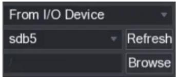
text_image
From I/O Device sdb5 Refresh BrowseClipping Recorded Video
During playback, clip sections of recorded video and save to the USB storage device.
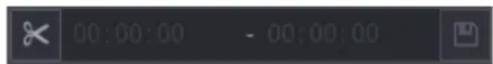
Step 1 Select a recorded video that you want to play.
- Click to start playing from the beginning.
- Double-click anywhere in the time bar colored area to start playback.
Step 2 Click on the time bar to select the start time, and then click to start clipping.
Step 3 Click on the time bar to select the start time, and then click to stop clipping.
Step 4 Click .
The BACKUP dialog box is displayed. You can back up the files.
NOTE
- You can clip the video of a single-channel or multiple channels.
• Maximum 1024 files can be backed up at one time. - The files that are selected in the File List cannot be clipped.
Backing up Recorded Video
You can back up the recorded video file or splice video file into the USB storage device.
Step 1 Select the recorded video file that you want to back up. You can select the following two types of files:
- Recorded video file: Click 📄, the File List area is displayed. Select the file(s)
that you want to back up. - Splice video file.
Step 2 Click
The BACKUP dialog box is displayed.
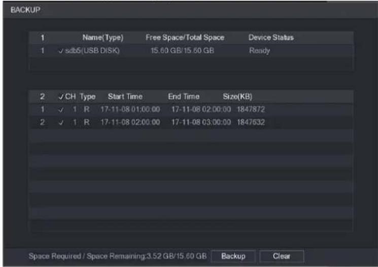
text_image
BACKUP 1 Name(Type) Free Space/Total Space Device Status 1 ✓ sdb6(USB DISK) 15.60 GB/15.60 GB Ready 2 ✓ CH Type Start Time End Time Size(KB) 1 ✓ 1 R 17-11-08 01:00:00 17-11-08 02:00:00 1847872 2 ✓ 1 R 17-11-08 02:00:00 17-11-08 03:00:00 1847632 Space Required / Space Remaining:3.52 GB/15.60 GB Backup ClearStep 3 Click Backup.
NOTE
If you do not want to backup the file, clear the check box.
Smart Search
During playback, you can analyze a certain area to find if there was any motion detection event occurred. The system will display the images with motion events of the recorded video.
To use the Smart Search function, you need to enable the motion detection for the channel by selecting Main Menu > ALARM > VIDEO DETECT > Motion Detect.
To use the Smart Search function, do the following:
Step 1 Select Main Menu > VIDEO, the video search interface is displayed.
Step 2 In the CAME NAME list, select the channel(s) that you want to play.
Step 3 Click ▶ double-click anywhere in the time bar colored area to start playback.
Step 4 Click
The grid is displayed on the screen.

NOTE
- Only single-channel supports smart search.
- If multi-channels are selected, double-click on the channel window to display this channel only on the screen, and then you can start using smart search function.
Step 5 Drag the pointer to select the searching area.

NOTE
The grid area supports 22×18.
Step 6 Click

The screen starts playing back the motional splices of recorded video for the selected searching area.
Step 7 Click

it the playback.
Marking and Playing Back Video
You can mark the recording for somewhere important. Then you can easily find the marked recording by searching time and mark name.
Marking a Video
Step 1 Select Main Menu > VIDEO, the video search interface is displayed.
Step 2 In the playback mode, click

The Add Mark dialog box is displayed.

text_image
Add Mark Mark Time 2017-11-08 04:28:22 Name Default OK CancelStep 3 In the Name box, enter a name.
Step 4 Click OK.
This marked video file displays in the Mark List.
Playing Back Marked Video

NOTE
This function is supported on single-channel playback.
Step 1 In the CAME NAME list, select one channel.
Step 2 Click

The Mark List interface is displayed.
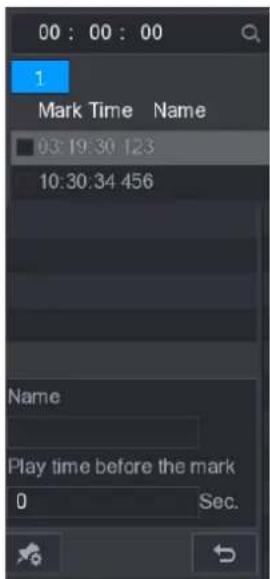
text_image
00 : 00 : 00 1 Mark Time Name 03:19:30 123 10:30:34 456 Name Play time before the mark 0 Sec.Step 3 Double-click the file that you want to play back.
To search the marked video by time, in the SEARCH box on the top of the interface,
enter the time, and then click

Playing Back Time before the Mark
You can configure to play N seconds of the marked video before the marked time.
Step 1 In the Name box, enter the name of a marked video.
Step 2 In the Playback time before the mark box, enter N seconds.
Step 3 Click

The playback starts from N seconds before the marked time.
NOTE
If there is N seconds exist before the marked time, the playback starts from N seconds before the marked time. If there is not, it plays back as much as there is.
Managing Marked Video
In the Mark List interface, click

the Manager interface is displayed.
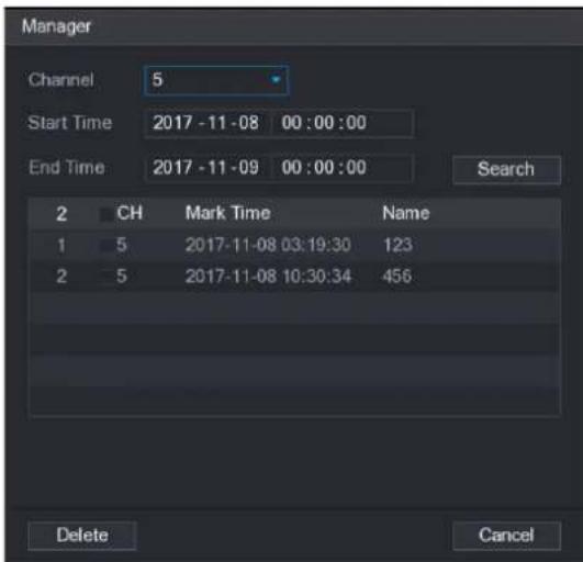
text_image
Manager Channel 5 Start Time 2017-11-08 00:00:00 End Time 2017-11-09 00:00:00 Search 2 CH Mark Time Name 1 5 2017-11-08 03:19:30 123 2 5 2017-11-08 10:30:34 456 Delete Cancel- Be default, it manages all the marked videos of the selected channel.
- To search the marked video, select channel number from the Channel list, enter time in Start Time box and End Time box, and then click Search.
- All the marked videos display in time order.
- To modify the name of marked video, double-click a marked video, the Edit Mark dialog box is displayed.
• To delete the marked video, select the marked video, and then click Delete.
NOTE
After opening the Manger interface, the playback will pause until exiting this interface. If the marked video that was in playing back is deleted, the playback will start from the first marked video in the Mark List.
Playing Back Snapshots
You can search and play back the snapshots.
Step 1 Select Main Menu > VIDEO, the video search interface is displayed.
Step 2 In the Search Type list, select PIC.
Step 3 In the Channel list, select a channel number.
Step 4 In the Calendar area, select a date.
Step 5 Click
The system starts playing snapshots according to the configured intervals.
Playing Back Splices
You can clip the recorded video files into splices and then play back at the same time to save your time.

NOTE
Not all models support this function.
Step 1 Select Main Menu > VIDEO, the video search interface is displayed.
Step 2 In the Search Type list, select Splice Playback; In the Split Mode list, select 4 or 9.
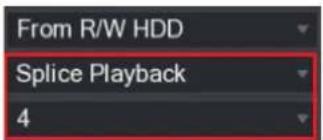
text_image
From R/W HDD Splice Playback 4Step 3 In the Calendar area, select a date.
Step 4 In the CAM NAME list, select a channel.

NOTE
Only single-channel supports this function.
Step 5 Start playing back splices.
- Click, the playback starts from the beginning.
- Double-click anywhere on the time bar, the playback starts from where you click.


NOTE
Every recorded video file must be at least five minutes. If a recorded video file is less than 20 minutes but still choose to split into four windows, the system will automatically adjust the windows quantity to ensure every splice is more than five minutes, and in this case it is possible that there are no images are displaying in some windows.
Using the File List
You can view all the recorded videos within a certain period from any channel in the File List.
Step 1 Select Main Menu > VIDEO, the video search interface is displayed.
Step 2 Select a channel(s).
Step 3 Click

The File List interface is displayed.
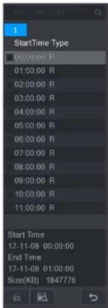
text_image
1 StartTime Type 00:00:00 R 01:00:00 R 02:00:00 R 03:00:00 R 04:00:00 R 05:00:00 R 06:00:00 R 07:00:00 R 08:00:00 R 09:00:00 R 10:00:00 R 11:00:00 R Start Time 17-11-08 00:00:00 End Time 17-11-08 01:00:00 Size(KB) 1847776Step 4 Start playback.
- Click ▶, the playback starts from the first file by default.
- Click any file, the system plays back this file.
NOTE
- In the time box on the top of the file list interface, you can enter the specific time to search the file that you want to view.
- In the File List area, there are 128 files can be displayed.
- File type: R indicates general recorded video; A indicates recorded video with external alarms; M indicates recorded video with motion detection events; I indicates recorded video with intelligent vents.
- Click to return to the interface with calendar and CAM NAME list.
Locking and Unlocking the Recorded Video
• To lock the recorded video, in the File List interface, select the check box of the recorded
video, and then click . The locked video will not be covered.
• To view the locked information, click 📄, the FILE LOCKED interface is displayed.
NOTE
The recorded video that is under writing or overwriting cannot be locked.
- To unlock the recorded video, in the FILE LOCKED interface, select the video, and then click Unlock.
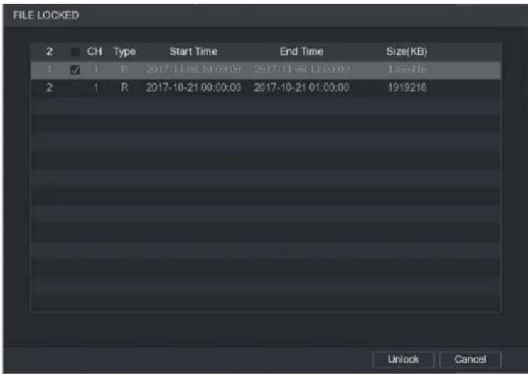
text_image
FILE LOCKED 2 CH Type Start Time End Time Size(KB) 1 1 R 2017-11-06 10:00:00 2017-11-06 11:00:00 195316 2 1 R 2017-10-21 00:00:00 2017-10-21 01:00:00 1919216 Unlock CancelAlarm Events Settings
Video Detection
Video detection adopts computer vision and image processing technology. The technology analyzes the video images to detect the obvious changes such as moving objects and blurriness. The system activates alarms when such changes are detected.
Configuring Motion Detect Settings
When the moving object appears and moves fast enough to reach the preset sensitivity value, the system activates the alarm.
To configure the motion detect settings, do the following:
Step 1 Select Main Menu > ALARM > VIDIEO DETECT > Motion Detect.
The Motion Detect interface is displayed.
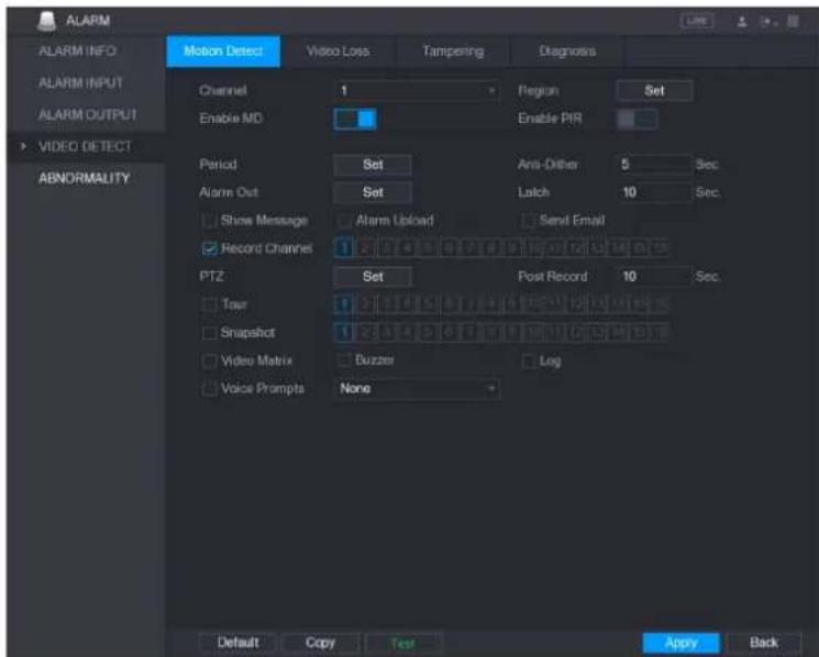
text_image
ALARM ALARM INFO ALARM INPUT ALARM OUTPUT VIDEO DETECT ABNORMALITY Motion Detect Video Loss Tampering Diagnosis Channel 1 Region Set Enable MD Enable PIR Period Set Anti-Other 5 Sec. Alarm Out Set Latch 10 Sec. Show Message Alarm Upload Send Email Record Channel 1 2 3 4 5 6 7 8 9 10 PTZ Set Post Record 10 Sec. Tour 1 2 3 4 5 6 7 8 9 Snapshot 1 2 3 4 5 6 7 8 9 Video Matrix Buzzer Log Voice Prompts None Default Copy Test Apply BackStep 2 Configure the settings for the motion detection parameters.
| Parameter | Description |
| Channel | In the Channel list, select a channel to set the motion detection. |
| Region | Click Setting to define the motion detection region. |
| Enable MD | Enable or disable the motion detection function. |
| Enable PIR | PIR function helps enhancing the accuracy and validity of motion detect. It can filter the meaningless alarms that are activated by the objects such as falling leaves, flies. The detection range by PIR is smaller than the field angle.PIR function is enabled by default if it is supported by the cameras. Enabling PIR function will get the motion detect to be enabled automatically to generate motion detection alarms; if the PIR function is not enabled, the motion detect just has the general effect.NOTEOnly when the channel type is CVI, the PIR function can be enabled.If the camera does not support PIR function, it will be unusable.If the Device does not support PIR function, it will not be displayed on the interface. |
| Period | Define a period during which the motion detection is active. |
| Anti-Dither | Configure the event detection lasting time. The system records only one event during this period. The value ranges from 5 seconds to 300 seconds. |
| Alarm Out | Click Setting to display setting interface.General Alarm: Enable alarm activation through the alarm devices connected to the selected output port.External Alarm: Enable alarm activation through the connected alarm box.Wireless Siren: Enable alarm activation through devices connected by USB gateway or camera gateway. |
| Latch | Set a length of time for the Device to delay turning off alarm after the external alarm is cancelled. The value ranges from 0 seconds to 300 seconds, and the default value is 10 seconds. If you enter 0, there will be no delay. |
| Show Message | Select the Show Message check box to enable a pop-up message in your local host PC. |
| Alarm Upload | Select the Alarm Upload check box to enable the system to upload the alarm signal to the network (including alarm center) when an alarm event occurs. |
| Send Email | Select the Send Email check box to enable the system to send an email notification when an alarm event occurs.NOTETo use this function, make sure the email function is enabled in Main Menu > NETWORK > EMAIL. |
| Record Channel | Select the channel(s) that you want to record. The selected channel(s) starts recording after an alarm event occurs.NOTEThe recording for motion detection and auto recording function must be enabled. |
| PTZ | Click Setting to display the PTZ interface.Enable PTZ activation function. For each PTZ camera, select the preset that you want to be called when an alarm event occurs.NOTEMotion Detect can only activate PTZ preset. |
| Post Record | Set a length of time for the Device to delay turning off recording after the alarm is cancelled. The value ranges from 10 seconds to 300 seconds, and the default value is 10 seconds. |
| Tour | Select the Tour check box to enable a tour of the selected channels.NOTETo use this function, make sure the tour is enabled and configured in Main Menu > DISPLAY > TOUR. |
| Snapshot | Select the Snapshot check box to take a snapshot of the selected channel. ⚪ NOTETo use this function, make sure the following settings are configured:• The snapshot function is enabled for motion detect alarms in Main Menu > STORAGE > SCHEDULE > Snapshot.• Select Main Menu > CAMERA > Snapshot, in the Mode list, select Event. |
| Video Matrix | Select the check box to enable the function. When an alarm event occurs, the video output port outputs the settings configured in Main Menu > DISPLAY > TOUR. ⚪ NOTENot all models support this function. |
| Buzzer | Select the check box to activate a buzzer noise at the Device. |
| Log | Select the check box to enable the Device to record a local alarm log. |
| Voice Prompts | Select to enable audio broadcast/voice prompts in response to a motion detection event. |
Step 3 Click Apply to save the settings.

NOTE
- Click Default to restore the default setting.
- Click Copy, in the Copy dialog box, select the additional channel(s) that you want to copy the motion detection settings to, and then click Apply.
- Click Test to test the settings.
Setting the Motion Detection Region
Step 1 Next to Region, click Setting.
The region setting screen is displayed.
Step 2 Point to the middle top of the interface.
The setting interface is displayed.

text_image
Name Region1 Sensitivity - + 80 Threshold - + 0Step 3 Configure the regions settings. You can configure totally four regions.
1) Select one region, for example, click .
2) Drag on the screen to select the region that you want to detect.
The selected area shows the color that represents the region.
3) Configure the parameters.
| Parameter | Description |
| Name | Enter a name for the region. |
| Sensitivity | Every region of every channel has an individual sensitivity value.The bigger the value is, the easier the alarms can be activated. |
| Threshold | Adjust the threshold for motion detect. Every region of every channel has an individual threshold. |
NOTE
When anyone of the four regions activates motion detect alarm, the channel where this region belongs to will activate motion detect alarm.
Step 4 Right-click on the screen to exit the region setting interface.
Step 5 On the Motion Detect interface, click Apply to complete the settings.
Setting Motion Detection Period
NOTE
The system only activates the alarm in the defined period.
Step 1 Next to Period, click Setting.
The Setting interface is displayed.
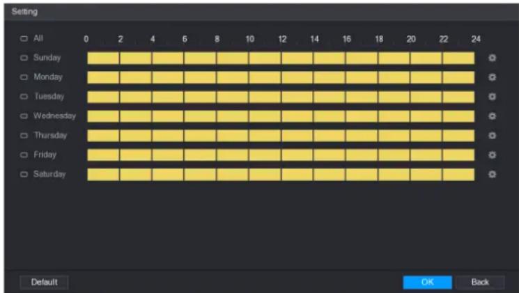
text_image
Setting All 0 2 4 6 8 10 12 14 16 18 20 22 24 Sunday Monday Tuesday Wednesday Thursday Friday Saturday Default OK BackStep 2 Define the motion detection period. By default, it is active all the time.
- Define the period by drawing.
☐ Define for a specified day of a week: On the timeline, click the half-hour blocks to select the active period.
◇ Define for several days of a week: Click □ before each day, the icon
switches to 📞. On the timeline of any selected day, click the half-hour
blocks to select the active periods, all the days with 📄 will take the same settings.
Define for all days of a week: Click All, all switches to On the timeline of any day, click the half-hour blocks to select the active periods, all the days will take the same settings.
- Define the period by editing. Take Sunday as an example.
1) Click

The Period interface is displayed.
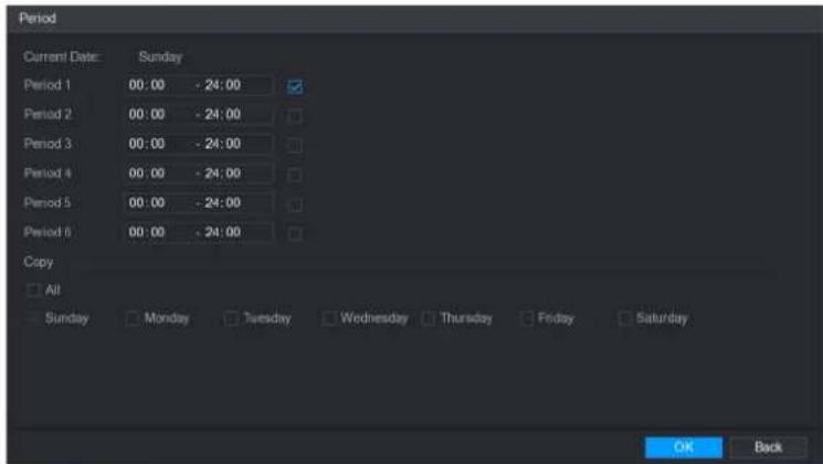
text_image
Period Current Date: Sunday Period 1 00:00 - 24:00 Period 2 00:00 - 24:00 Period 3 00:00 - 24:00 Period 4 00:00 - 24:00 Period 5 00:00 - 24:00 Period 6 00:00 - 24:00 Copy All Sunday Monday Tuesday Wednesday Thursday Friday Saturday OK Back2) Enter the time frame for the period and select the check box to enable the settings.
◇ There are six periods for you to set for each day.
Under Copy, select All to apply the settings to all the days of a week, or select specific day(s) that you want to apply the settings to.
3) Click OK to save the settings.
Step 3 On the Motion Detect interface, click Apply to complete the settings.
Configuring Video Loss Settings
When the video loss occurs, the system activates the alarm. To configure the motion detect settings, do the following:
Step 1 Select Main Menu > ALARM > VIDIEO DETECT > Video Loss.
The Video Loss interface is displayed.
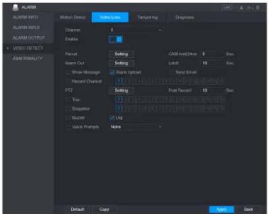
text_image
ALARM ALARM INFO ALARM INPUT ALARM OUTPUT VIDEO DETECT ABNORMALITY Motion Detect Video Line Temping Ring Diagnosis Channel 1 Enable Period Setting CAM AudioDriver $ Sec. Alarm Out Setting Latch 10 Sec. Show Message Alarm Update Send Signal Record Channel PTZ Setting Post Record 10 Sec. True Sequence Blurzer Ling Voice Pragms None Default Copy Next BackStep 2 Configure the settings for the video loss detection parameters"
Step 3 Click Apply to complete the settings.
NOTE
- Click Default to restore the default setting.
- Click Copy, in the Copy dialog box, select the additional channel(s) that you want to copy the motion detection settings to, and then click Apply.
Configuring Tampering Settings
When the camera lens is covered, or the video is displayed in a single color because of the causes such as sunlight status, the monitoring cannot be continued normally. To avoid such situations, you can configure the tampering alarm settings.
Step 1 Select Main Menu > ALARM > VIDIEO DETECT > Tampering.
The Tampering interface is displayed.
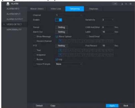
text_image
ALARM ALARM INFO ALARM INPUT ALARM OUTPUT VIDEO DETECT ABNORMALITY Multi-Select Video Loss Targeting Diagnoses Channel Enable Sensitivity 3 Period Setting CAM And Other 9 Reset Alarm Out Setting Locks 10 Scan Show Message Alarm Upset Send Email Record Channel 1 PID Setting Post Record 10 Scan Text 1 Imputation 1 Buffer Log Voice Prompt None Default Copy Apply BackStep 2 Configure the settings for the tampering detection
Step 3 Click Apply to complete the settings.

NOTE
- Click Default to restore the default setting.
- Click Copy, in the Copy dialog box, select the additional channel(s) that you want to copy the motion detection settings to, and then click Apply.
Configuring Diagnosis Settings

NOTE
This function can be used only when it is supported by the camera.
When the video appear the conditions such as blurry, overexposed, or the color changes, the system activates the alarm.
To configure the diagnosis settings, do the following:
Step 1 Select Main Menu > ALARM > VIDIEO DETECT > Diagnosis.
The Diagnosis interface is displayed.

text_image
ALARM ALARM INFO ALARM INPUT ALARM OUTPUT VIDEO DETECT ABNORMALITY Motion Detect Video Loss Tampering Diagnosis Channel Enable 1 Rule Setting Period Alarm Out Setting Latch 10 Sec Show Message Alarm Upload Send Email Buzzer Log Voice Prompts None Default Apply BackStep 2 Configure the settings for the diagnosis parameters"
Step 3 Click Apply to complete the settings.

NOTE
Click Default to restore the default setting.
Setting the Types for Diagnosing Targets
Step 1 Next to Rule, click Setting.
The Diagnosis interface is displayed.
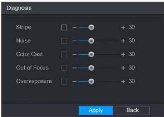
text_image
Diagnosis Stripe - + 30 Noise - + 30 Color Cast - + 30 Out of Focus - + 30 Overexposure - + 30 Apply BackStep 2 Select the items that you want to diagnose and set the threshold (30 by default).
| Parameter | Description |
| Stripe | A horizontal, vertical or diagonal stripe that might appear in the video because of device aging or electronic interruption. Such stripe brings visual interruption. |
| Noise | Video noises such as blurriness or quality reduction that is caused by optical distortion or device problem during camera shooting. |
| Color Cast | Variances in the normal proportions of RGB colors. |
| Out of Focus | Blurry video is caused during camera shooting, transferring and processing. Such condition is a common image quality reduction problem and defined as out of focus. |
| Overexposure | The video brightness refers to the intensity of image pixel. The range is between 0 (the darkest black) and 255 (the brightest white). If the brightness exceeds the threshold, the image is over exposed. |
| Threshold | The range is from 1 through 100. If the value after diagnosing is higher than what you set, the system activates the alarm to the corresponding diagnosing types such as stripe. |
Step 3 Click OK to save the settings.
The system returns to the Diagnosis interface.
Step 4 Click Apply to complete the settings.
NOTE
Click Default to restore the default setting.
IVS Function

NOTE
Please disable IP channels function first before using IVS function.
IVS function processes and analyzes the images to extract the key information to match with the preset rules. When the detected behaviors match with the rules, the system activates alarms.
Step 1 Select Main Menu > IVS > INTELL SETTING.
The INTELL SETTING interface is displayed.

text_image
INTELL BETTING Channel Enable Name Type Preset Add Apply CancelStep 2 In the Channel list, select the channel number that you want to configure the IVS function for.
Step 3 Click Add.
One line of rule is displayed.

text_image
INS INTELL SETTING Channel 1 Enable Name Type Preset Limit Travers Add Apply CancelStep 4 Configure the parameters for the rule that you selected.
Step 5 Select the check box of the rule to enable it.
Step 6 Click Apply to complete the settings.
Configuring Tripwire Rules
When the target object crosses the tripwire in the defined direction, the system activates alarms.
- The tripwire can be configured as a straight line or broken line.
• Supports detecting one-way or two-way tripwire crossing.
• Supports multiple tripwires in the same scenario to meet the complexity.
• Supports size filtering for target.
Step 1 On the rule line that you added, in the Type list, select Tripwire.

text_image
INS INTELL SETTING Channel 1 Enable Name Type Project 1 Rule1 Trigger Add Apply CancelStep 2 Draw a tripwire.
1) In the Channel list, select the channel that you want to configure the rules for.
2) Click

The monitoring screen to configure the tripwire rules is displayed.
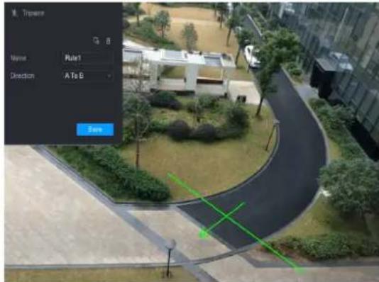
text_image
Travem Name Rule1 Direction A to S OK3) Configure the settings for the parameters of drawing rules.
| Parameter | Description |
| Name | Enter the customized rule name. |
| Direction | Set the direction of the tripwire. You can choose A to B (left to right), B to A (right to left), and Both. |
| Filtering Target | Click draw areas to filter the target.NOTEYou can configure two filtering targets (maximum size and minimum size). When the target that is crossing the tripwire is smaller than the minimum size or larger than the maximum size, no alarms will be activated. The maximum size should be larger than the minimum size. |
4) Drag to draw a tripwire. The tripwire can be a straight line, broken line or polygon.
5) Click Save to save the settings.
Step 3 Click to set the actions to be triggered.
The Trigger interface is displayed.

text_image
Trigger Period Set Alarm Out Set Latch 10 Sec. Show Message ✓ Alarm Upload ✓ Send Email ✓ Record Channel 1 2 3 4 5 6 7 8 9 10 11 12 13 14 15 16 PTZ Set Post Record 10 Sec. Tour 1 2 3 4 5 6 7 8 9 10 11 12 13 14 15 16 Snapshot 1 2 3 4 5 6 7 8 9 10 11 12 13 14 15 16 Video Matrix Buzzer ✓ Log Voice Prompts None- OK BackStep 4 Configure the triggering parameters.
| Parameter | Description |
| Period | ClickSetto display set interface.Define a period during which the motion detection is active. |
| Alarm Out | ClickSettingto display setting interface.General Alarm: Enable alarm activation through the alarm devices connected to the selected output port.External Alarm: Enable alarm activation through the connected alarm box.Wireless Siren: Enable alarm activation through devices connected by USB gateway or camera gateway. |
| Latch | Set a length of time for the Device to delay turning off alarm after the external alarm is cancelled. The value ranges from 0 seconds to 300 seconds, and the default value is 10 seconds. |
| Show Message | Select theShow Messagecheck box to enable a pop-up message in your local host PC. |
| Alarm Upload | Select the Alarm Upload check box to enable the system to upload the alarm signal to the network (including alarm center) when an alarm event occurs. |
| Send Email | Select the Send Email check box to enable the system to send an email notification when an alarm event occurs. |
| Record Channel | Select the channel(s) that you want to record. The selected channel(s) starts recording after an alarm event occurs. |
| PTZ | Click Set to display the PTZ interface. Enable PTZ activation function. For each PTZ camera, select the preset that you want to be called when an alarm event occurs. |
| Post Record | Set a length of time for the Device to delay turning off recording after the alarm is cancelled. The value ranges from 10 seconds to 300 seconds, and the default value is 10 seconds. |
| Tour | Select the Tour check box to enable a tour of the selected channels. |
| Snapshot | Select the Snapshot check box to take a snapshot of the selected channel. |
| Video Matrix | Select the check box to enable the function. When an alarm event occurs, the video output port outputs the settings configured in "Main Menu > Display > Tour." |
| Buzzer | Select the check box to activate a buzzer noise at the Device. |
| Log | Select the check box to enable the Device to record a local alarm log. |
| Voice Prompts | Select to enable audio broadcast/voice prompts in response to a motion detection event. |
Step 5 Click Apply to save the settings.
The INTELL SETTING interface is displayed.
Step 6 Select the Enable check box, and then click Apply.
The tripwire detecting function is active. When the target object crosses the tripwire in the defined direction, the system activates alarms.
Configuring Intrusion Rules
When the target enters and leaves the area, or the target appears in the defined area, the system activates alarms.
- You can define the shape and quantity of intrusion areas.
• Supports detecting the behaviors that enter and leave the intrusion areas. - Supports detecting the behaviors that are moving in the intrusion areas. The quantity of areas and lasting time can be configured.
• Supports size filtering for target.
Step 1 On the rule line that you added, in the Type list, select Intrusion.
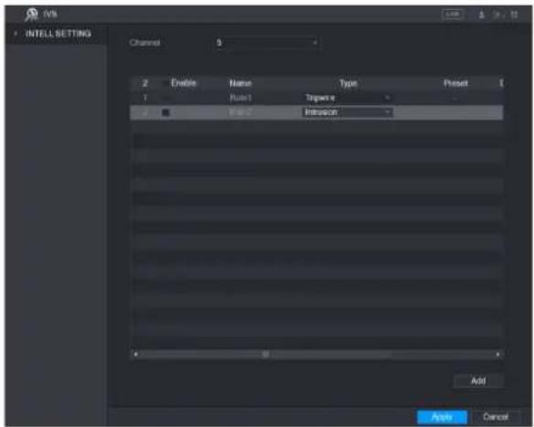
text_image
INTELL SETTING Channel 3 2 Enable Name Type Project 1 Rule1 Signature 2 0.000000000000000000000000000000000000000000000000000000000000000000000000000000000 Add Apply CancelStep 2 Draw a tripwire.
1) In the Channel list, select the channel that you want to configure the rules for.
2) Click

The monitoring screen to configure the intrusion rules is displayed.
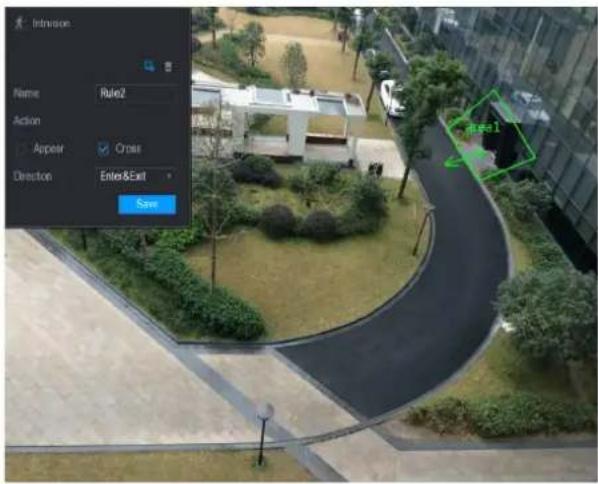
text_image
Intrusion Name Rule2 Action Appear Cross Direction Enter&Exit Save Area 13) Configure the settings for the parameters of drawing rules.
| Parameter | Description |
| Name | Enter the customized rule name. |
| Action | Configure the actions that are defined as intrusion. You can select theAppear check box and theCross check box. |
| Direction | In the Direction list, select the direction of crossing the configured area. You can select Enter&Exit, Enters, and Exits. |
| Filtering Target | Click to draw areas to filter the target.NOTEYou can configure two filtering targets (maximum size and minimum size). When the target that is crossing the tripwire is smaller than the minimum size or larger than the maximum size, no alarms will be activated. The maximum size should be larger than the minimum size. |
4) Drag to draw an area.
5) Click Save to save the settings.
Step 3 Click to set the actions to be triggered."
Step 4 Select the Enable check box, and then click Apply.
The intrusion detecting function is active. When the target enters and leaves the area, or the target appears in the defined area, the system activates alarms.
Configuring Abandoned Rules
When the object is placed in the defined detection area for more than the set time, the system activates alarms.
- You can define the shape and quantity of intrusion areas.
• Period value can be configured.
• Supports size filtering for target.
Step 1 On the rule line that you added, in the Type list, select Abandoned. The Abandoned interface is displayed.
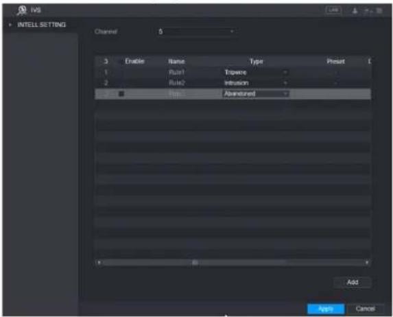
text_image
INS INTELL SETTING Channel 5 3 Enable Name Type Preset 1 Rule1 Triscore 2 Rule2 Inversion ■ Top Abandoned Add Apply CancelStep 2 Draw an area.
1) In the Channel list, select the channel that you want to configure the rules for.
2) Click

The monitoring screen to configure the abandoned rules is displayed.

text_image
Abandoned Name: Rule3 Format: 30 Sec: Save:3) Configure the settings for the parameters of drawing rules.
| Parameter | Description |
| Name | Enter the customized rule name. |
| Period | Configure the minimum time period for activating alarms by detecting the abandoned objects. |
| Filtering Target | Clickdraw areas to filter the target.NOTEYou can configure two filtering targets (maximum size and minimum size). When the target that is crossing the tripwire is smaller than the minimum size or larger than the maximum size, no alarms will be activated. The maximum size should be larger than the minimum size. |
4) Drag to draw an area.
5) Click Save to save the settings.
Step 3 Click to set the actions to be triggered."
Step 4 Select the Enable check box, and then click Apply.
The abandoned object detecting function is active. When the object is placed in the defined detection area for more than the set time, the system activates alarms.
Configuring Missing Rules
When the target is taken away from the defined area exceeds the set time, the system activates alarms.
Step 1 On the rule line that you added, in the Type list, select Missing.
The Missing interface is displayed.
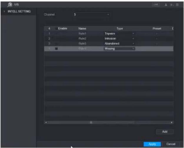
text_image
INTELL SETTING Channel 5 4 Enable Name Type Preset 1 Rule1 Tipwire 2 Rule2 Infusion 3 Rule3 Abandoned 4 Rule4 Missing Add Apply CancelStep 2 Draw an area.
1) In the Channel list, select the channel that you want to configure the rules for.
2) Click

The monitoring screen to configure the missing rules is displayed.
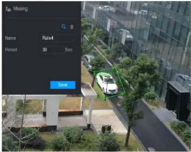
text_image
Missing Name Rule4 Period 30 Sec. Save3) Configure the settings for the parameters of drawing rules.
| Parameter | Description |
| Name | Enter the customized rule name. |
| Period | Configure the minimum time period for activating alarms by detecting the missing objects. |
| Filtering Target | Click draw areas to filter the target.NOTEYou can configure two filtering targets (maximum size and minimum size). When the target that is crossing the tripwire is smaller than the minimum size or larger than the maximum size, no alarms will be activated. The maximum size should be larger than the minimum size. |
4) Drag to draw an area.
5) Click Save to save the settings.
Click to set the actions to be triggered.
Step 3 Select the Enable check box, and then click Apply.
The missing object detecting function is active. When the target is taken away from the defined area exceeds the set time, the system activates alarms.
Face Detection
You can configure the face detection settings and search the detected faces in the defined time period.
Configuring Face Detection Settings
When the Device detects the human faces, the system activates alarms.
NOTE
- Not all models support this function.
• Smart IPC must be equipped with face detect function.
Step 1 Select Main Menu > FACE DETECT > Parameters.
The Human Face interface is displayed.
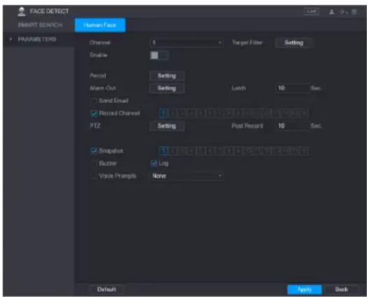
text_image
FACE DETECT SMART SEAFCH PARAMETERS Turnout Face Channel 1 Enable Period Setting Alarm Out Setting Latch 10 Sec. Send Email Record Channel 1.25A11.10A11.10A11.10A11.10A11.10A11.10A PT2 Setting Post Record 10 Sec. Snapshot 1.25A11.10A11.10A11.10A11.10A Buzzer Log Voice Prompts None Default Apply BackStep 2 Configure the settings for the face detection parameters.
| Parameter | Description |
| Channel | In the Channel list, select a channel to set the face detection. |
| TargetFilter | Click Setting to draw areas to filter the target.NOTEYou can configure two filtering targets (maximum size and minimum size). When the target is smaller than the minimum size or larger than the maximum size, no alarms will be activated. The maximum size should be larger than the minimum size. |
| Enable | Enable or disable the face detection function. |
| Period | Define a period during which the motion detection is active. |
| Alarm Out | Click Setting to display setting interface.Enable alarm activation function. Select the alarm output port(s) to which the peripheral alarm devices are connected. When an alarm event occurs, the system activates the peripheral alarm devices connected to the selected output port. |
| Latch | Set a length of time for the Device to delay turning off alarm after the external alarm is cancelled. The value ranges from 0 seconds to 300 seconds, and the default value is 10 seconds. If you enter 0, there will be no delay. |
| Send Email | Select the Send Email check box to enable the system to send an email notification when an alarm event occurs.NOTETo use this function, make sure the email function is enabled in Main Menu > NETWORK > EMAIL. |
| Record Channel | Select the channel(s) that you want to record. The selected channel(s) starts recording after an alarm event occurs.NOTEThe recording for intelligence event and auto recording function must be enabled. |
| PTZ | Click Setting to display the PTZ interface.Enable PTZ activation function. For each PTZ camera, select the preset that you want to be called when an alarm event occurs.NOTEMotion Detect can only activate PTZ preset. |
| Post Record | Set a length of time for the Device to delay turning off recording after the alarm is cancelled. The value ranges from 10 seconds to 300 seconds, and the default value is 10 seconds. |
| Snapshot | Select the Snapshot check box to take a snapshot of the selected channel.NOTETo use this function, make sure the following settings are configured:The snapshot function is enabled for motion detect alarms in Main Menu > STORAGE > SCHEDULE > Snapshot.Select Main Menu > CAMERA > ENCODE > Snapshot, in the Mode list, select Event. |
| Buzzer | Select the check box to activate a buzzer noise at the Device. |
| Log | Select the check box to enable the Device to record a local alarm log. |
| Voice Prompts | Select to enable audio broadcast/voice prompts in response to a human face detection event. |
Step 3 Click Apply to complete the settings.
Searching for Detected Faces
Step 1 Select Main Menu > FACE DETECT > SMART SEARCH.
The SMART SEARCH interface is displayed.
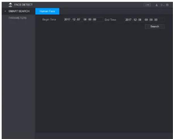
text_image
FACE DETECT SMART SEARCH Human Face PARAMETERS Begin Time 2017 - 12 - 07 06 : 00 : 00 End Time 2017 - 12 - 08 09 : 00 : 00 SearchStep 2 In the Begin Time box and End Time box, enter the time.
Step 3 Click Search.
The faces searched in the defined period display.
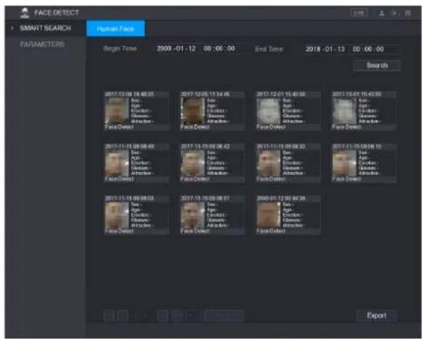
text_image
FACE DETECT SMART SEARCH HUMAN FACE PARAMETERS Begin Time 2900-01-12 00:00:00 End Time 2018-01-13 00:00:00 Search FaceDirect FaceDirect FaceDirect FaceDirect FaceDirect FaceDirect 2017-12-08 14:46:35 Eye Eye Eye Eye Eye Eye Eye Eye Eye Eye Eye Eye Eye Eye Eye Eye Eye Eye Eye Eye Eye Eye Eye Eye Eye Eye Eye Eye Eye Eye Eye Eye Eye Eye Eye Eye Eye Eye Eye Eye Eye Eye Eye Eye Eye Eye Eye Eye Eye Eye FaceDirect FaceDirect FaceDirect FaceDirect FaceDirect FaceDirect FaceDirect FaceDirect FaceDirect FaceDirect FaceDirect FaceDirect FaceDirect FaceDirect FaceDirect FaceDirect FaceDirect FaceDirect FaceDirect FaceDirect FaceDirect FaceDirect FaceDirect FaceDirect FaceDirect FaceDirect FaceDirect FaceDirect FaceDirect FaceDirect FaceDirect FaceDirect FaceDirect FaceDirect FaceDirect FaceDirect FaceDirect FaceDirect FaceDirect FaceDirect FaceDirect FaceDirect FaceDirect FaceDirect FaceDirect FaceDirect FaceDirect FaceDirect FaceDirect FaceDirect FaceDirect Skin 2017-12-05 11:34:45 Eye Eye Eye Eye Eye Eye Eye Eye Eye Eye Eye Eye Eye Eye Eye Eye Eye Eye Eye Eye Eye Eye Eye Eye Eye Eye Eye Eye Eye Eye Eye Eye Eye Eye Eye Eye Eye Eye Eye Eye Eye Eye Eye Eye Eye Eye Eye Eye EyeSystem Events
You can configure the alarm output for three types of system event (HDD, Network, and User). When there is an abnormal system event occurs, the system activates alarms in the way that you configure in this section.
Configuring HDD Event Settings
Step 1 Select Main Menu > ALARM > ABNORMITY > HDD.
The HDD interface is displayed.

text_image
ALARM ALARM INFO ALARM INPUT ALARM OUTPUT VIDEO DETECT AENORMALITY HDD Network User Device Event Type No HDD Enable Alarm Out Setting Latch Y0 Sec. Show Message Alarm Uploaded Send Email Begin Log Voice Prompts None Apply BackStep 2 Configure the settings for the HDD event.
| Parameter | Description |
| Event Type | In the Event Type list, select No HDD, HDD Error, or HDD No Space as the event type. |
| Enable | Enable or disable the HDD event detection function. |
| Alarm Out | Click Setting to display setting interface.General Alarm: Enable alarm activation through the alarm devices connected to the selected output port.External Alarm: Enable alarm activation through the connected alarm box.Wireless Siren: Enable alarm activation through devices connected by USB gateway or camera gateway. |
| Latch | Set a length of time for the Device to delay turning off alarm after the external alarm is cancelled. The value ranges from 10 seconds to 300 seconds, and the default value is 10 seconds. |
| Show Message | Select the Show Message check box to enable a pop-up message in your local host PC. |
| Alarm Upload | Select the Alarm Upload check box to enable the system to upload the alarm signal to the network (including alarm center) when an alarm event occurs. |
| Send Email | Select the Send Email check box to enable the system to send an email notification when an alarm event occurs.NOTETO use this function, make sure the email function is enabled in Main Menu > NETWORK > EMAIL. |
| Buzzer | Select the check box to activate a buzzer noise at the Device. |
| Log | Select the check box to enable the Device to record a local alarm log. |
| Voice Prompts | Select to enable audio broadcast/voice prompts in response to a HDD alarm event. |
Step 3 Click Apply to complete the settings.
Configuring Network Event Settings
Step 1 Select Main Menu > ALARM > ABNORMITY > Network.
The Network interface is displayed.
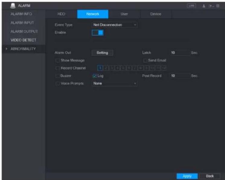
text_image
ALARM ALARM INFO ALARM INPUT ALARM OUTPUT VIDEO DETECT ABNORMALITY HDD Network User Device Event Type Net Disconnection Enable Alarm Out Setting Latch 10 Sec Show Message Send Email Record Channel 1 2 3 4 5 6 7 8 9 10 11 12 Buzzer Log Post Record 10 Sec Voice Prompts None Apply BackStep 2 Configure the settings for the Network event.
| Parameter | Description |
| Event Type | In the Event Type list, select Net Disconnection, IP Conflicted, or MAC Conflicted as the event type. |
| Enable | Enable or disable the Network event detection function. |
| Alarm Out | Click Setting to display setting interface.General Alarm: Enable alarm activation through the alarm devices connected to the selected output port.External Alarm: Enable alarm activation through the connected alarm box.Wireless Siren: Enable alarm activation through devices connected by USB gateway or camera gateway. |
| Latch | Set a length of time for the Device to delay turning off alarm after the external alarm is cancelled. The value ranges from 10 seconds to 300 seconds, and the default value is 10 seconds. |
| Show Message | Select the Show Message check box to enable a pop-up message in your local host PC. |
| Send Email | Select the Send Email check box to enable the system to send an email notification when an alarm event occurs.NOTETo use this function, make sure the email function is enabled in Main Menu > NETWORK > EMAIL. |
| Buzzer | Select the check box to activate a buzzer noise at the Device. |
| Log | Select the check box to enable the Device to record a local alarm log. |
| Voice Prompts | Select to enable audio broadcast/voice prompts in response to a network alarm event. |
Step 3 Click Apply to complete the settings.
Configuring User Event Settings
Step 1 Select Main Menu > ALARM > ABNORMITY > User.
The User interface is displayed.
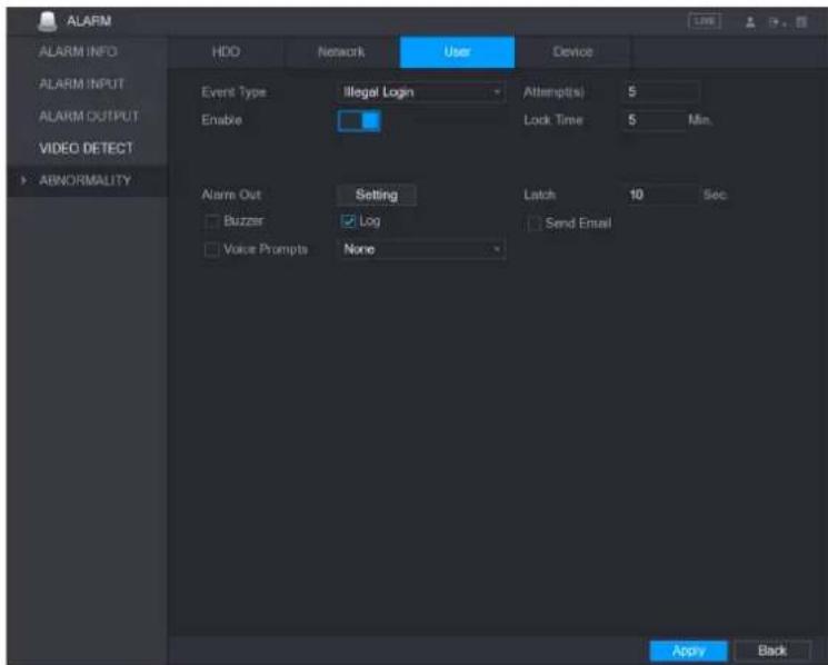
text_image
ALARM ALARM INFO ALARM INPUT ALARM OUTPUT VIDEO DETECT ABNORMALITY HDD Network User Device Event Type Illegal Login Attempts 5 Enable Lock Time 5 Min. Alarm Out Setting Latch 10 Sec Buzzer Log Send Email Voice Prompts None Apply BackStep 2 Configure the settings for the User event.
| Parameter | Description |
| Event Type | In the Event Type list, select Illegal Login. |
| Enable | Enable the user error detection function.If you do not enable this function, there will be no limit for wrong password entry and the account cannot be locked because of the wrong password. |
| Attempt(s) | Set the maximum number of allowable wrong password entries. The account will be locked after your entries exceed the maximum number. |
| Lock Time | Set how long the account is locked for. The value ranges from 1 minute to 60 minutes. |
| Alarm Out | Click Setting to display setting interface.General Alarm: Enable alarm activation through the alarm devices connected to the selected output port.External Alarm: Enable alarm activation through the connected alarm box.Wireless Siren: Enable alarm activation through devices connected by USB gateway or camera gateway. |
| Latch | Set a length of time for the Device to delay turning off alarm after the external alarm is cancelled. The value ranges from 10 seconds to 300 seconds, and the default value is 10 seconds. |
| Send Email | Select the Send Email check box to enable the system to send an email notification when an alarm event occurs.NOTETo use this function, make sure the email function is enabled in Main Menu > NETWORK > EMAIL. |
| Buzzer | Select the check box to activate a buzzer noise at the Device. |
| Log | Select the check box to enable the Device to record a local alarm log. |
| Voice Prompts | Select to enable audio broadcast/voice prompts in response to a user account alarm event. |
Step 3 Click Apply to complete the settings.
Configuring Device Event Settings
Step 1 Select Main Menu > ALARM > ABNORMITY > Device.
The Device interface is displayed.
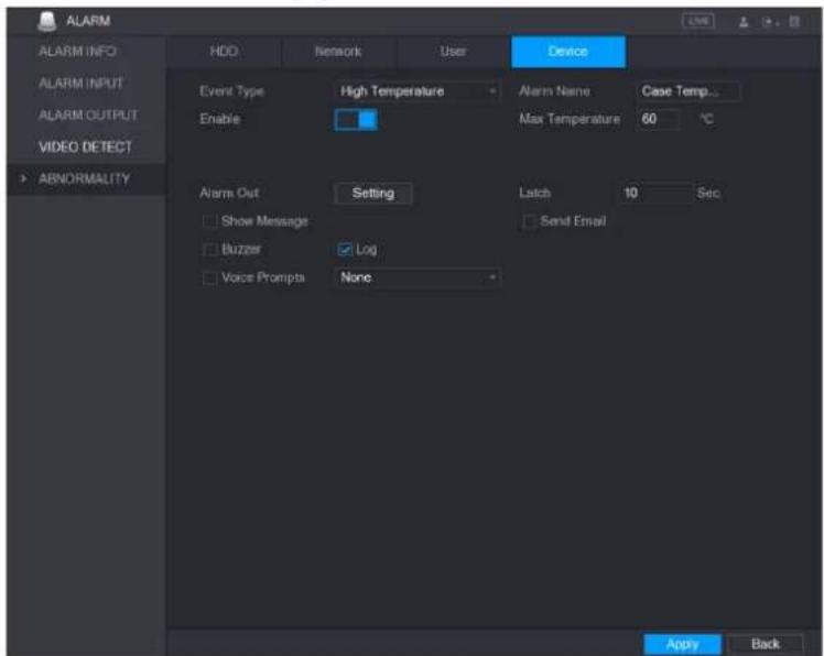
text_image
ALARM ALARM INFO ALARM INPUT ALARM OUTPUT VIDEO DETECT ABNORMALITY HDD Network User Device Event Type High Temperature Alarm Name Case Temp... Enable Max Temperature 60 °C Alarm Out Setting Latch 10 Sec Show Message Send Email Buzzer Log Voice Prompts None Apply BackStep 2 Configure the settings for the device event.
| Parameter | Description |
| Event Type | In the Event Type list, select High Temperature or Fan Speed Abnormal. |
| Alarm Name | Enter the name for the event type. |
| Enable | Enable the device event detection function. |
| Max Temperature | In the Max Temperature box, enter the max temperature value. |
| Alarm Out | Click Setting to display setting interface.General Alarm: Enable alarm activation through the alarm devices connected to the selected output port.External Alarm: Enable alarm activation through the connected alarm box.Wireless Siren: Enable alarm activation through devices connected by USB gateway or camera gateway. |
| Latch | Set a length of time for the Device to delay turning off alarm after the external alarm is cancelled. The value ranges from 10 seconds to 300 seconds, and the default value is 10 seconds. |
| Send Email | Select the Send Email check box to enable the system to send an email notification when an alarm event occurs.NOTETo use this function, make sure the email function is enabled in Main Menu > NETWORK > EMAIL. |
| Buzzer | Select the check box to activate a buzzer noise at the Device. |
| Log | Select the check box to enable the Device to record a local alarm log. |
| Voice Prompts | Select to enable audio broadcast/voice prompts in response to a Device alarm event. |
Step 3 Click Apply to complete the settings.
Configuring Backup Settings
Finding USB Device
When you inset a USB storage device into the USB port of the Device, the Device detects the USB storage device and pops up "Find USB device" interface, which provides you a shortcut to perform backup and upgrading operations.

text_image
Find USB device. Name: sda5(USB DISK) Capacity: 15.60 GB/15.60 GB(Free/Total) File Backup Log Backup Config Backup System UpgradeBacking up Files
You can back up the recorded videos and snapshots.
Step 1 Select Main Menu > BACKUP.
The BACKUP interface is displayed.
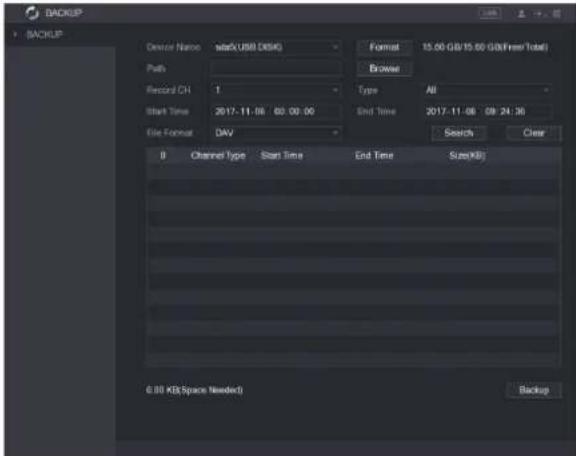
text_image
BACKUP BACKUP Device Name start(USB DISK) Path Record CH 1 Start Time 2017-11-06 00:00:00 File Format DAV Format 15.00 GB/15.00 GB(Free Total) Browser Type All End Time 2017-11-08 08:24:36 Search Clear B Channel type Start Time End Time Size(Kil) 0.00 KB(Space Needed) BackupStep 2 Configure the settings for the backup parameters.
| Parameter | Description |
| Device Name | In the Device Name list, select the device that you want to back up the files to. |
| Format | Click Format to format the selected device. |
| Path | Click Browse, the Browse interface is displayed. Select the route where you want to search for the files. |
| Record CH | In the Record CH list, select the channel where you want to search for the files. |
| Type | In the Typelist, select the file type that you want to search. |
| Start Time | Enter the start time and end time for the files that you want to search. |
| End Time | |
| File Format | In the File Format list, select the file format that you want to search. |
Step 3 Click Search to search the files that meet the configured settings.
The searched results will display in the table.
Step 4 Select the files that you want to back up.
Step 5 Click Backup to back up the selected files to the configured path.
NOTE
Click Clear to remove all the searched results.
Network Management
Configuring Network Settings
You can ensure the network interworking between the Device and other devices through configuring the network settings.
Configuring TCP/IP Settings
You can configure the settings for the Device such as IP address, DNS according to the networking plan.
Select Main Menu > NETWORK > TCP/IP, the TCP/IP interface is displayed."
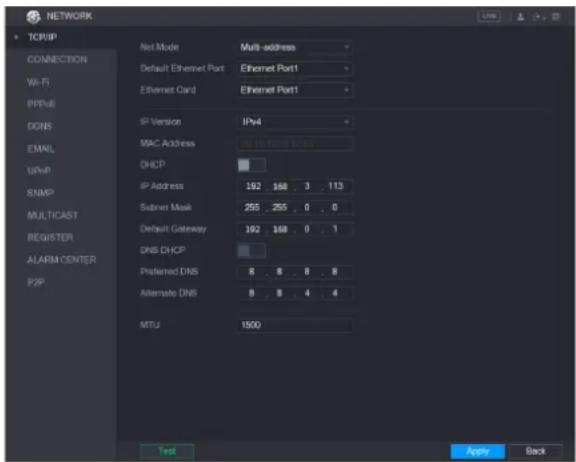
text_image
NETWORK TCP/IP NET MODE Mult address Default Ethernet Port Ethernet Port1 Ethernet Card Ethernet Port1 IP Version IPv4 MAC Address 168.168.162 DHCP IP Address 192 168 . 3 . 113 Submit Mask 255 . 255 . 0 . 0 Default Gateway 192 168 . 0 . 1 DNS DHCP Preferred DNS 8 . 8 . 8 . 8 Alternate DNS 8 . 8 . 4 . 4 MTU 1500 Test Apply BackConfiguring Port Settings
You can configure the maximum connection accessing the system.
Step 1 Select Main Menu > NETWORK > CONNECTION.
The CONNECTION interface is displayed.
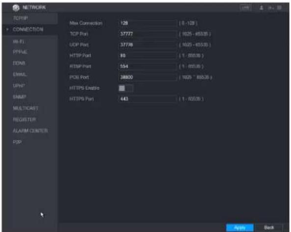
text_image
NETWORK TCP/IP CONNECTION Wi-Fi PPFEIE DONS EMAIL UPPS EAMIP MULTICAST REGISTUR ALARM COUNTER POP Max Connection 128 (0 - 128) TCP Port 37777 (1025 - 65335 ) UDP Port 37778 (1025 - 65335 ) HTTP Port 89 (1 - 65335 ) RTSP Port 154 (1 - 65335 ) PCB Port 38800 (1025 - 65335 ) HTTPS Enable HTTPS Port 443 (1 - 65335 ) Apply BackStep 2 Configure the settings for the connection parameters.
NOTE
The connection parameters except Max Connection cannot take effects until the Device has been restarted.
| Parameter | Description |
| Max Connection | The allowable maximum clients accessing the Device at the same time, such as WEB, Platform, and Mobile Phone.Select a value between 1 and 128. The default value setting is 128. |
| TCP Port | The default value setting is 37777. You can enter the value according to your actual situation. |
| UDP Port | The default value setting is 37778. You can enter the value according to your actual situation. |
| HTTP Port | The default value setting is 80. You can enter the value according to your actual situation.If you enter other value, for example, 70, and then you should enter 70 after the IP address when logging in the Device by browser. |
| RTSP Port | The default value setting is 554. You can enter the value according to your actual situation. |
| POS Port | Data transmission. The value range is from 1 through 65535. The default value is 38800. |
| HTTPS Enable | Enable HTTPS. |
| HTTPS Port | HTTPS communication port. The default value setting is 443. You can enter the value according to your actual situation. |
Step 3 Click Apply to complete the settings.
Configuring Wi-Fi Connection Settings
You can make wireless connection between the Device and the other devices in the same network through Wi-Fi settings, facilitating the devices connection and mobility.

Only the Device with Wi-Fi module supports this function.
Step 1 Select Main Menu > NETWORK > Wi-Fi.
The Wi-Fi interface is displayed.

text_image
NETWORK TOMIP CONNECTION Wi-Fi Auto Connect 0 SSD Signal Intensity Wi-Fi Working Info PPPoE DONS EMAIL UPnP SNMP MULTICAST REGISTER ALARM CENTER POP Current Hotspot No Connection IP Address Subnet Mask Default Gateway Refresh Apply BackStep 2 Configure the settings for the Wi-Fi connection parameters.
| Parameter | Description |
| Wi-Fi Auto Connect | Enable Wi-Fi Auto Connect.After the Device is restarted, it will automatically connect to the nearest hotspot that had been connected successfully. |
| Refresh | Refresh the hotspot list. The self-adaption function such as adding password is supported if such setting was once configured. |
| Connect | In the hotpots list, select a hotspot, and then click Connect.To reconnect the same hotspot, disconnect first and then reconnect.To connect to other hotspot, disconnect from the current connected hotspot first, and then connect to the other hotspot. |
| Disconnect | To disconnect from a hotspot, click Disconnect. |
Step 3 Click Apply to complete the settings.
After the Device is connected to a Wi-Fi hotspot, in the Wi-Fi Working Info area, the current hotspot, IP address, subnet mask, and default gateway are displayed.
Configuring PPPoE Settings
PPPoE is another way for the Device to access the network. You can establish network connection by configuring PPPoE settings to give the Device a dynamic IP address in the
WAN. To use this function, firstly you need to obtain the user name and password from the Internet Service Provider.
Step 1 Select Main Menu > NETWORK > PPPoE.
The PPPoE interface is displayed.

text_image
NETWORK TCP/IP CONNECTION WiFi PPPvE DCNS EMAIL UPnP SNMP MULTICAST REGISTER ALARM CENTER P2P Enable User Name Password IP Address Apply BackStep 2 Enable the PPPoE function.
Step 3 In the User Name box and Password box, enter the user name and password accordingly provided by the Internet Service Provider.
Step 4 Click Apply to complete the settings.
The system pops up a message to indicate the successfully saved. The IP address appears on the PPPoE interface. You can use this IP address to access the Device.
NOTE
When the PPPoE function is enabled, the IP address on the TCP/IP interface cannot be modified.
Configuring EMAIL Settings
You can configure the email settings to enable the system to send the email as a notification when there is an alarm event occurs.
Step 1 Select Main Menu > NETWORK > EMAIL.
The EMAIL interface is displayed.
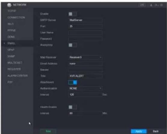
text_image
NETWORK TCP/IP CONNECTION Wi-Fi PPUE DONE EMAIL USBIP SNMP MULTICAST REGISTER ALARM CENTER POP Enable SMTP Server MailServer Port 25 User Name Password Anonymity Mail Receiver Receiver3 Email Address name Sender Title XVR ALERT Attachment Authentication NONE Interval 120 Sec. Health Enabling Interval 60 Min. Test Apply BackStep 2 Configure the settings for the email parameters.
| Parameter | Description |
| Enable | Enable the email function. |
| SMTP Server | Enter the address of SMTP server of sender's email account. |
| Port | Enter the port value of SMTP server. The default value setting is 25. You can enter the value according to your actual situation. |
| User Name | Enter the user name and password of sender's email account. |
| Password | |
| Anonymity | If enable the anonymity function, you can login as anonymity. |
| Mail Receiver | In the Mail Receiver list, select the number of receiver that you want to receive the notification. The Device supports up to three mail receivers. |
| Email Address | Enter the email address of mail receiver(s). |
| Sender | Enter the sender's email address. It supports maximum three senders separated by comma. |
| Title | Enter the email subject.Supports Chinese, English and Arabic numerals. It supports maximum 64 characters. |
| Attachment | Enable the attachment function. When there is an alarm event, the system can attach snapshots as an attachment to the email. |
| Authentication | Select the encryption type: NONE, SSL, or TLS. |
| Interval (Sec.) | This is the interval that the system sends an email for the same type of alarm event, which means, the system does not send an email upon any alarm event.This setting helps to avoid the large amount of emails caused by frequent alarm events.The value ranges from 0 to 3600. 0 means that there is no interval. |
| Health Enable | Enable the health test function. The system can send a test email to check the connection. |
| Interval (Min.) | This is the interval that the system sends a health test email.The value ranges from 30 to 1440. 0 means that there is no interval. |
| Test | Click Test to test the email sending function. If the configuration is correct, the receiver's email account will receive the email.NOTEBefore testing, click Apply to save the settings. |
Step 3 Click Apply to complete the settings.
Configuring UPnP Settings
You can map the relationship between the LAN and the WAN to access the Device on the LAN through the IP address on the WAN.
Preparation for Configuration
- Login the router to set the WAN port to enable the IP address to connect into the WAN.
- Enable the UPnP function at the router.
- Connect the Device with the LAN port on the router to connect into the LAN.
- Select Main Menu > NETWORK > TCP/IP, configure the IP address into the router IP address range, or enable the DHCP function to obtain an IP address automatically.
Configuration Steps
Step 1 Select Main Menu > NETWORK > UPnP.
The UPnP interface is displayed.
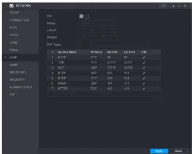
text_image
NETWORK TCP/IP CONNECTION Wi-Fi FPR/C DONE EMAIL USBIP SNMP MULTICAST REGISTER ALARM CENTER DOP PAT Status LAN IP WAN IP PAT Table 7 Service Name Protocol Ind. Port Ext. Port Edit 1 HTTP TCP 80 80 ✓ 2 TCP TCP 37777 37777 ✓ 3 UDP UDP 37778 37778 ✓ 4 RTSP UDP 554 554 ✓ 5 RTSP TCP 554 554 ✓ 6 SNMP UDP 161 161 ✓ 7 HTTPS TCP 443 443 ✓ Apply BackStep 2 Configure the settings for the UPnP parameters.
| Parameter | Description |
| PAT | Enable the UPnP function. |
| Status | Indicates the status of UPnP function.Offline: Failed.Online: Succeeded. |
| LAN IP | Enter IP address of router on the LAN.NOTEAfter mapping succeeded, the system obtains IP address automatically without performing any configurations. |
| WAN IP | Enter IP address of router on the WAN.NOTEAfter mapping succeeded, the system obtains IP address automatically without performing any configurations. |
| PAT Table | The settings in PAT table correspond to the UPnP PAT table on the router.Service Name: Name of network server.Protocol: Type of protocol.Int. Port: Internal port that is mapped on the Device.Ext. Port: External port that is mapped on the router.NOTETo avoid the conflict, when setting the external port, try to use the ports from 1024 through 5000 and avoid popular ports from 1 through 255 and system ports from 256 through 1023.When there are several devices in the LAN, please reasonably arrange the ports mapping to avoid mapping to the same external port.When establishing a mapping relationship, please ensure the mapping ports are not occupied or limited.The internal and external ports of TCP and UDP must be the same and cannot be modified.Click to modify the external port. |
Step 3 Click Apply to complete the settings.
In the browser, enter http://WAN IP: External IP port. You can visit the LAN Device.
Configuring P2P Settings
You can manage the devices by using P2P technology to download the application and register the devices."
Configuring Network Testing Settings
Testing the Network
You can test the network connection status between the Device and other devices.
Step 1 Select Main Menu > INFO > NETWORK > Test.
The Test interface is displayed.

text_image
INFO VERSION LOG EVENT NETWORK HDD DEVICE STATUS CHANNEL INFO BPS Online User Network Load Network Test Network Test Destination IP Test Result Network Sifter Packet Backup Device Name: sdb5(USB DISK) Address: / Name IP Sifter Packet Size Sifter Packet Backup LAW1 192.368.00 13 OKS Refresh BrowseStep 2 In the Destination IP box, enter the IP address.
Step 3 Click Test
After testing is completed, the test result is displayed. You can check the evaluation for average delay, packet loss, and network status.
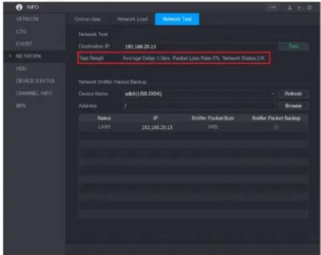
text_image
INFO VERSION LOG EVENT NETWORK HDD DEVICE STATUS CHANNEL INFO BPS Online User Network Load Network Test Network Test Destination IP: 192.168.20.13 Test Result: Average Delay: 1.0ms Packet Loss Rate: 0% Network Status OK Network Snifter Packet Backup Device Name: sdb5(USB DISK) Address: / Name IP Snifter Packet Size Snifter Packet Backup LAN1 192.168.20.13 OKSCapturing Packet and Backing up
Packet capture means the operations such as capturing, resending, and editing data that are sent and received during network transmission. When there is network abnormality, you can
perform packet capturing and back up into the USB storage device. This date can be provided to the technical support for analyzing the network condition.
Step 1 Select Main Menu > INFO > NETWORK > Network Test.
The Network Test interface is displayed.

text_image
INFO VERSION LOG EVENT NETWORK HDD DEVICE STATUS CHANNEL INFO GPS Online User Network Load Network Test Network Test Destination IP: 192.168.20.19 Test Result Average Delay: 1 Sms Packet Lose Rate: 8% Network Status: OK Network Transfer Packet Backup Device Name: xdb5(USB DISK) Address: Refresh Browse Name IP Snifter Packet Size Snifter Packet Backup LAW1 192.168.20.19 OKS 0Step 2 Connect a USB storage device to the Device.
Step 3 Click Fresh.
The Device starts detecting the USB storage device and displays its name in the Device Name box.
Step 4 Select the route of the data that you want to capture and back up.
1) In the Network Sniffer Packet Backup, click Browse.
The Browse interface is displayed.

text_image
Browse Device Name:sdb5(USB DISK) Refresh Total Space 15.60 GB Free Space 15.60 GB Address / Name Size Type Delete Play IP Folder 否 RemoteConfig_20171103141044.csv 464 B File 否 printf_20171105172349.txt 451.3 KB File 否 krmg_print_20171105172349.txt 14.9 KB File 否 New Folder OK Back2) Select the route.
NOTE
- If there are several USB storage devices are connected to the Device, you can select from the Device Name list.
- Click Refresh to total space, free space and the file list in the selected USB storage device.
- In the case of insufficient capacity, click to delete the needless files.
- Click New Folder to create a new folder in the USB storage device.
3) Click Apply to save the route selection settings.
The Test interface is displayed again.
Step 5
Click

to start packet capturing and backing up.

NOTE
- Only the data packet of one LAN can be captured at one time.
- After capturing starts, you can exit the Test interface to perform other operations such as web login and monitoring.
Step 6
Click

to stop capturing.
The backup data is saved in the selected route under the naming style "LAN name-time.pcap."
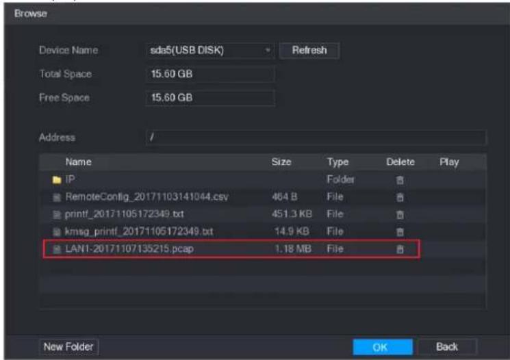
text_image
Browse Device Name sds5(USB DISK) Refresh Total Space 15.60 GB Free Space 15.60 GB Address // Name Size Type Delete Play IP Folder # RemoteConfig_20171103141044.csv 464 B File # printf_20171105172349.txt 451.3 KB File # kmsg_printf_20171105172349.txt 14.9 KB File # LAN1-20171107135215.pcap 1.18 MB File # New Folder OK BackConfiguring Account Settings
You can add, modify and delete user accounts, groups, and ONVIF users, and set security questions for admin account.

NOTE
- The user name supports 31 characters and group name supports 15 characters. The user name can be consisted of letter, number, " _ ", "@", " .".
- You can set maximum 64 users and 20 groups. The group name by "User" and "Admin" cannot be deleted. You can set other groups and define the relevant permissions. However, the admin account cannot be set randomly.
- You can manage the account by user and group and the name cannot be repeated. Every user must belong to a group, and one user only belongs to one group.
Configuring User Account
Adding a User Account
Step 1 Select Main Menu > ACCOUNT > USER.
The USER interface is displayed.
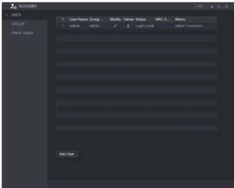
text_image
ACCOUNT USER GROUP ONVIP USER 1 User Name Group ... Modify Delete Status MAC A... Memo 1 admin admin Login Local admin 'a account Add UserStep 2 Click Add User.
The Add User interface is displayed
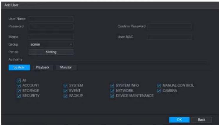
text_image
Add User User Name Password Memo Group admin Period Setting Authority System Playback Monitor All ACCOUNT SYSTEM SYSTEM INFO MANUAL CONTROL STORAGE EVENT NETWORK CAMERA SECURITY BACKUP DEVICE MAINTENANCE OK BackStep 3 Configure the settings for the parameters of adding a user account.
| Parameter | Description |
| User Name | Enter a user name and password for the account. |
| Password | |
| Confirm Password | Re-enter the password. |
| Memo | Optional.Enter a description of the account. |
| User MAC | Enter user MAC address |
| Group | Select a group for the account.NOTEThe user rights must be within the group permission. |
| Period | Click Set to display Set interface.Define a period during which the new account can login the device. The new account cannot login the device during the time beyond the set period. |
| Authority | In the Authority area, select the check boxes in the System tab,Playback tab, and Monitor tab.NOTETo manage the user account easily, when defining the user account authority, it is recommended not to give the authority to the common user account higher that the advanced user account. |
Step 4 Click OK to complete the settings.
Setting Permitted Period
Step 1 Next to Period, click Setting. The Setting interface is displayed.

text_image
Set All 0 2 4 6 8 10 12 14 16 18 20 22 24 Sunday Monday Tuesday Wednesday Thursday Friday Saturday Default Apply BackStep 2 Define the permitted period. By default, it is active all the time.
- Define the period by drawing.
Define for a specified day of a week: On the timeline, click the half-hour blocks to select the active period.
Define for several days of a week: Click before each day, the icon switches to in the timeline of any selected day, click the half-hour blocks to select the active periods, all the days with will take the same settings.
Define for all days of a week: Click All, all the switches to On the timeline of any day, click the half-hour blocks to select the active periods, all the days will take the same settings.
- Define the period by editing. Take Sunday as an example.
1) Click

The Period interface is displayed.

text_image
Period Current Date Sunday Period 1 00:00 -24:00 Period 2 00:00 -24:00 Period 3 00:00 -24:00 Period 4 00:00 -24:00 Period 5 00:00 -24:00 Period 6 00:00 -24:00 Core All Sunday Monday Tuesday Wednesday Thursday Friday Saturday OK Back2) Enter the time frame for the period and select the check box to enable the settings.
◇ There are six periods for you to set for each day.
Under Copy, select All to apply the settings to all the days of a week, or select specific day(s) that you want to apply the settings to.
3) Click OK to save the settings.
Step 3 Click OK.
Modify a User Account
Step 1 Select Main Menu > ACCOUNT > USER.
The USER interface is displayed.

text_image
ACCOUNT USER GROUP ON/IF USER 1 User Name Group . . . Modify Delete Status MAC A... Memo 1 admin admin . . . Login Local admin % account Add UserStep 2 Click for the user account that you want to modify.
The Modify User interface is displayed.

text_image
Modify User User Name admin Modify Password Old Password New Password Confirm Password Prompt Question 1 Authority System Playback Monitor User MAC Email Address 2***@qq.com Group Memo Unlock Pattern Security Questions All ACCOUNT SYSTEM MANUAL CONTROL STORAGE EVENT CAMERA SECURITY BACKUP DEVICE MAINTENANCE OK BackStep 3 Change the settings for password, user name, user group, user MAC, memo, period, and authority.
NOTE
The new password can be set from 8 digits through 32 digits and contains at least two types from number, letter and special characters (excluding "", "", :, ", " and "&").
For the admin account, you can enter or modify email address, enable/disable the unlock pattern, modify the security questions.
- In the Email Address box, enter the email address, and the click Save to save the setting.
- To use the unlock pattern, enable Unlock Pattern, click 📄, draw a pattern in the Unlock Pattern interface, and then click Save to save the setting.
- Configuring security questions.
1) Click Security Questions. The Security Questions interface is displayed.
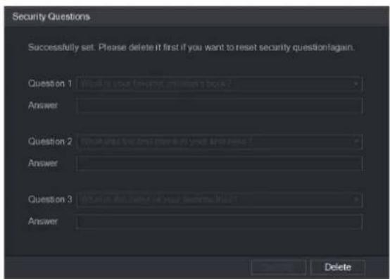
text_image
Security Questions Successfully set. Please delete it first if you want to reset security question again. Question 1 What is your forward answer in book? Answer Question 2 Where is the first answer in your answer? Answer Question 3 Where is the second answer in your answer?? Answer Delete2) In the Question list, select questions and enter the answers in the Answer box.
3) Click Setting to save the settings.
You can use the security questions and answers to reset the password for admin account.

NOTE
To reset the security questions, on the Security Questions, enter the correct answers for each question, and then click Delete.
Step 4 Click OK to complete the settings.
Deleting a User Account
Step 1 Select Main Menu > ACCOUNT > USER.
The USER interface is displayed.
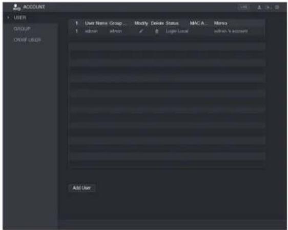
text_image
ACCOUNT USER GROUP ORANGE_USER 1 User Name Group... Modify Delete Status MAC A... Memo 1 admin admin 8 Logit Local admin & account Add UserStep 2 Click for the user account that you want to delete.
A Message is displayed.
Step 3 Click OK to delete a user account.
Configuring Group Account
Adding a Group
Step 1 Select Main Menu > ACCOUNT > GROUP.
The GROUP interface is displayed.
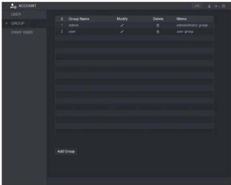
text_image
ACCOUNT USER GROUP ONVIF USER 2 Group Name Modify Delete Memo 1 admin ✓ 0 administrator group 2 user ✓ 0 user group Add GroupStep 2 Click Add Group.
The Add Group interface is displayed.
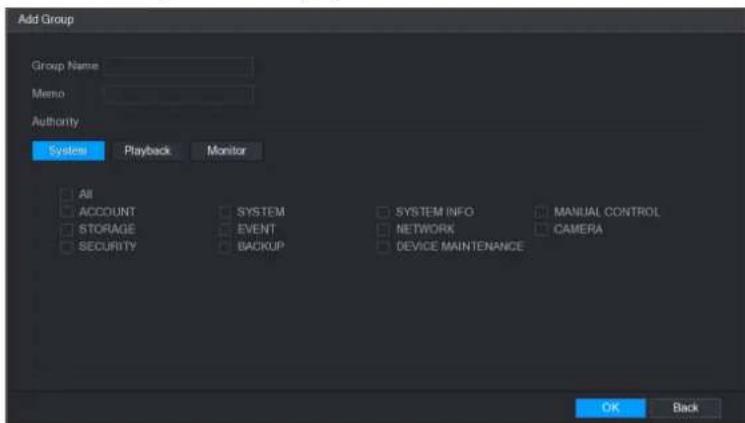
text_image
Add Group Group Name Memo Authority System Playback Monitor All ACCOUNT SYSTEM SYSTEM INFO MANUAL CONTROL STORAGE EVENT NETWORK CAMERA SECURITYBACKUP DEVICE MAINTENANCE OK BackStep 3 Configure the settings for the parameters of adding a group.
| Parameter | Description |
| Group Name | Enter a name for the group. |
| Memo | Optional.Enter a description of the account. |
| Authority | In the Authority area, select the check boxes in the System tab,Playback tab, and Monitor tab. |
Step 4 Click OK to complete the settings.
Modifying a Group
Step 1 Select Main Menu > ACCOUNT > GROUP.
The GROUP interface is displayed.
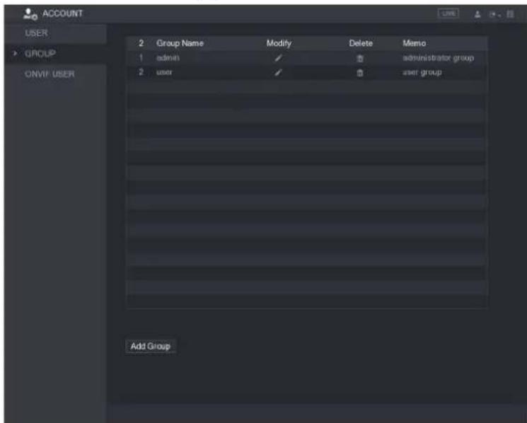
text_image
ACCOUNT USER GROUP ONVIF USER 2 Group Name Modify Delete Memo 1 admin ✓ Administrator group 2 user ✓ user group Add GroupStep 2 Click for the group account that you want to modify.
Step 3 The Modify Group interface is displayed.

text_image
Modify Group Group user Group Name user Memo user group Authority System Playback Monitor All ACCOUNT SYSTEM SYSTEM INFO MANUAL CONTROL STORAGE EVENT NETWORK CAMERA SECURITY BACKUP DEVICE MAINTENANCE OK BackStep 4 Change the settings for group name, memo, and authority.
Step 5 Click OK to complete the settings.
Deleting a Group
Step 1 Select Main Menu > ACCOUNT > GROUP.
The GROUP interface is displayed.
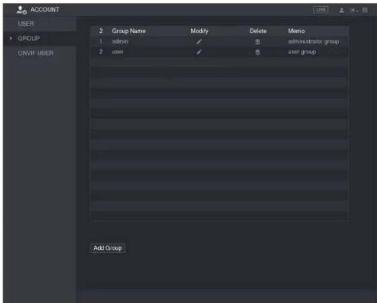
text_image
ACCOUNT USER GROUP ONVIP USER 2 Group Name Modify Delete Memo 1 admin ✓ Administrator group 2 user ✓ user group Add GroupStep 2 Click for the user account that you want to delete.
A Message is displayed.
Step 3 Click OK to delete a group.
Configuring Onvif Users
The device manufactured by other company can connect to the Device through Onvif protocol by an authorized Onvif account.
NOTE
The admin account is created for Onvif users right after the Device has been initialized Step 1 Select Main Menu > ACCOUNT > ONVIF USER.
The ONVIF USER interface is displayed.
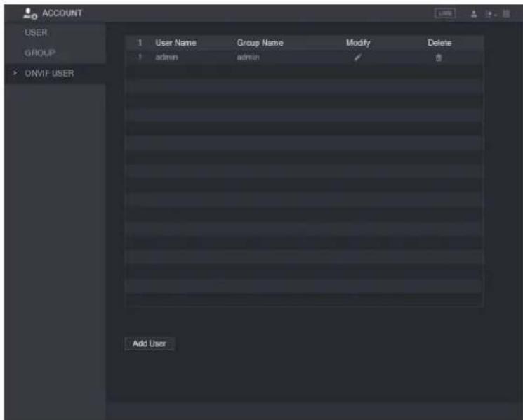
text_image
ACCOUNT USER GROUP ONVIF USER 1 User Name Group Name Modify Delete 1 admin admin 0 Add UserStep 2 Click Add User.
The Add User interface is displayed.

text_image
Add User User 123 Password Confirm Password Group admin OK BackStep 3 Enter user name, password, and select the group that you want this account to belong to.
Step 4 Click OK to save the settings.

NOTE
Click

modify the account; Click


e the account.
Storage Management
Storage management function manages the stored resources such as recorded video files and storage space. The function aims at providing easier operation and improving the storage efficiency.
Configuring Basic Settings
Step 1 Select Main Menu > STORAGE > BASIC.
The BASIC interface is displayed.
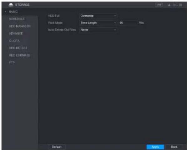
text_image
STORAGE BASIC SCHEDULE HDD MANAGER ADVANCE QUOTA HDD DETECT RED ESTIMATES FTP HDD Fill Overwrite Pack Mode Time Length 80 Min Auto-Delete Old Files Never Default Apply BackStep 2 Configure the settings for the basic settings parameters.
| Parameter | Description |
| HDD Full | Configure the settings for the situation all the read/write discs are full, and there is no more free disc.Select Stop Record to stop recordingSelect Overwrite to overwrite the recorded video files always from the earliest time. |
| Pack Mode | Configure the time length and file length for each recorded video. |
| Auto-Delete Old Files | Configure whether to delete the old files and if yes, configure the N days. |
Step 3 Click Apply to complete the settings.
Configuring the Recording and Snapshot Schedule
The system starts recording and taking snapshot according to the configured schedule.
Configuring HDD Manager
You can view the HDD information, format HDD, and configure the HDD type through HDD manager.
Step 1 Select Main Menu > STORAGE > HDD MANAGER.
The HDD MANAGER interface is displayed.
In the table, you can view the information of current HDD, such as device name, HDD type, status, total space and free space, and serial number of the HDD port.
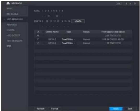
text_image
STORAGE BASIC SCHEDULE HDD MANAGER ADVANCE QUOTA HDD DETECT RED ESTIMATE FTP SATA 1 2 3 4 5 6 7 8 O O ESATA 9 10 11 12 13 14 15 16 eDATA 2 Device Name Type Status Free Space/Total Space All 2.00 TB/5.43 TB 1" SATA-3 ReadWhite - Normal 18.54 GB/21.40 GB 2 SATA-6 ReadWhite - Normal 1.00 TB/2.72 TB Refresh Format Apply BackStep 2 Configuring the settings for the HDD manager.
- HDD type setting: In the Type list, select Read/Write, Read-Only or Redundant, and then click Apply to save the settings.
- HDD format: Select the HDD that you want to format, click Format, in the pop-up message, click OK to start formatting, and then following the onscreen message to complete formatting.
Configuring HDD Group
You can configure the HDD group to save the specified main stream, sub stream and snapshots to the designated HDD group.

CAUTION
- If "Current HDD Mode is Quota Mode" is shown on the interface, you need to switch to HDD mode.
- You can enable either HDD Mode or Quota Mode at one time. The system reboots to activate the settings.
Step 1 Select Main Menu > STORAGE > ADVANCE.
The ADVANCE interface is displayed.
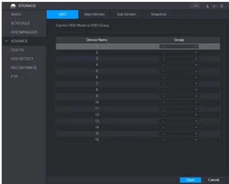
text_image
STORAGE BASIC SCHEDULE HDD MANAGER ADVANCE QUOTA HDD DETECT REC ESTIMATE FTP HDD Main Stream Sub Stream Snapshot Current HDD Mode is HDD Group. Device Name Group 1 - 2 - 3 - 4 - 5 - 6 - 7 - 8 - 9 - 10 - 11 - 12 - 13 - 14 - 15 - 16 - Save CancelStep 2 Select the group for each HDD group, and then click Save to save the settings.
Step 3 After configuring HDD group, under the Main Stream tab, Sub Stream tab and Snapshot tab, configure settings to save the main stream, sub stream and snapshot to different HDD group as selected by you.

text_image
STORAGE BASIC SCHEDULE HDD MANAGER ADVANCE QUOTA HDD DETECT REC ESTIMATE FTP HDD Main Stream Sub Stream Snapshot Current HDD Mode is HDD Group. Set All Channels 1 All Channel Group Channel Group Channel Group Channel Group 1 1 2 1 3 1 4 1 5 1 6 1 7 1 8 1 9 1 10 1 11 1 12 1 13 1 14 1 15 1 16 1 Apply Cancel
text_image
STORAGE BASIC SCHEDULE HDD MANAGER ADVANCE QUOTA HDD DETECT REC ESTIMATE FTP HDD Main Stream Sub Stream Snapshot Current HDD Mode is HDD Group. Set All Channels 1 All Channel Group Channel Group Channel Group Channel Group 1 1 2 1 3 1 4 1 5 1 6 1 7 1 8 1 9 1 10 1 11 1 12 1 13 1 14 1 15 1 16 1 Apply CancelStep 4 Click Apply to complete the settings.
Configuring HDD Detecting Settings

NOTE
Not all models support this function.
HDD detecting function detects the current status of HDD to let you know the HDD performance and replace the defective HDD.
Detecting HDD
You can detect HDD by quick detect and global detect.
- Quick detect: Detect the files saved in HDD. The detected bad track can be repaired by formatting. If there are no files in HDD, the system cannot detect the bad track.
- Global detect: Detect the whole HDD through Windows, which takes time and might affect the HDD that is recording the video.
Step 1 Select Main Menu > STORAGE > HDD DETECT > Detect.
The Detect interface is displayed.
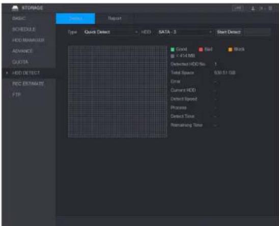
text_image
STORAGE BASIC SCHEDULE HDD MANAGER ADVANCE QUOTA HDD DETECT REC ESTIMATE FTP Device Report Type Quick Detect HDD SATA - 3 Start Detect Good Red Black = 454 MB Detected HDD No. 1 Total Space 630.51 GB Error Current HDD Detected Speed Process Detected Time Remaining TimeStep 2 In the Type list, select Quick Detect or Global Detect; and in the HDD list, select the HDD that you want to detect.
Step 3 Click Start Detect.
The system starts detecting the HDD.
During detecting, click Pause to pause detecting, click Continue to restart detecting, and click Stop Detect to stop detecting.
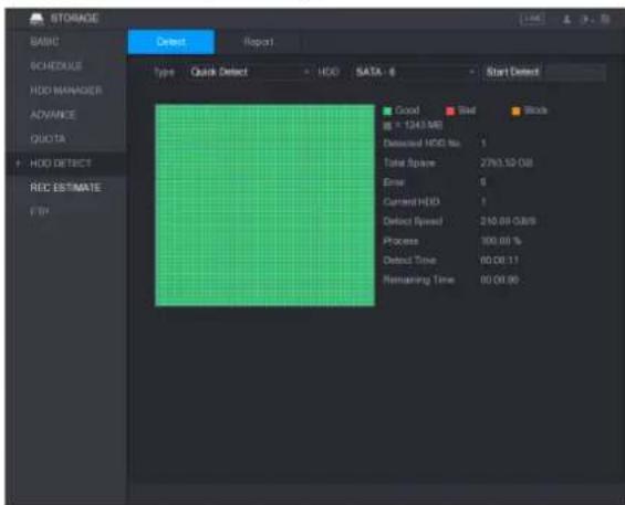
text_image
STORAGE BASIC SCHEDULE HDD MANAGER ADVANCE QUOTA HDD DETECT RED ESTIMATE FIR Detect Report1 Type Quick Detect HDD SATA - 6 Start Detect Good Bad Block = (343.94) Detected HDD No: Total Space: 2793.52 GB Error: 0 Current HDD: Detect Speed: 210.00 GB/8 Process: 100.00 % Detect Time: 00.00.11 Remaining Time: 00.00.00View Detecting Results
After the detecting is completed, you can view the detecting reports to find out the problem and replace the defective HDD to avoid data loss.
Step 1 Select Main Menu > STORAGE > HDD DETECT > Report.
The Report interface is displayed.

text_image
BASIC SCHEDULE HDD MANAGER ADVANCE: QUOTA HDD DETECT REC ESTIMATE FTP Detect Report 1 HDD Port No. Detect Type Start Time Capacity Error View 1 3 Quick Detect 2017-11-07... 830.51 GB 0Step 2 Click

The Details interface is displayed. You can view detecting results and S.M.A.R.T reports.
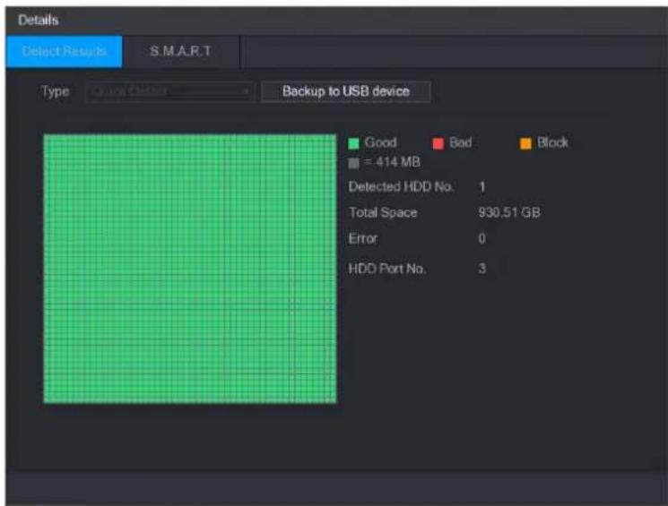
text_image
Details Select Results S.M.A.R.T Type Quick Delay Backup to USB device Good Bad Block = 414 MB Detected HDD No. 1 Total Space 930.51 GB Error 0 HDD Port No. 3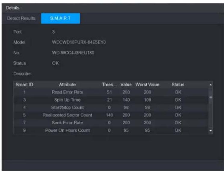
text_image
Details Detect Results S.M.A.R.T Port 3 Model WDCWD10PURX-64ESEY0 No. WD-WCC4J3REU180 Status OK Describe: Smart ID Attribute Thres... Value Worst Value Status 1 Read Error Rate 51 200 200 OK 3 Spin Up Time 21 140 108 OK 4 Start/Stop Count 0 98 98 OK 5 Reallocated Sector Count 140 200 200 OK 7 Seek Error Rate 0 200 200 OK 9 Power On Hours Count 0 95 95 OKConfiguring Record Estimate
Record estimate function can calculate how long you can record video according to the HDD capacity, and calculate the required HDD capacity according to the record period.
Step 1 Select Main Menu > STORAGE > REC ESTIMATE.
The REC ESTIMATE interface is displayed.
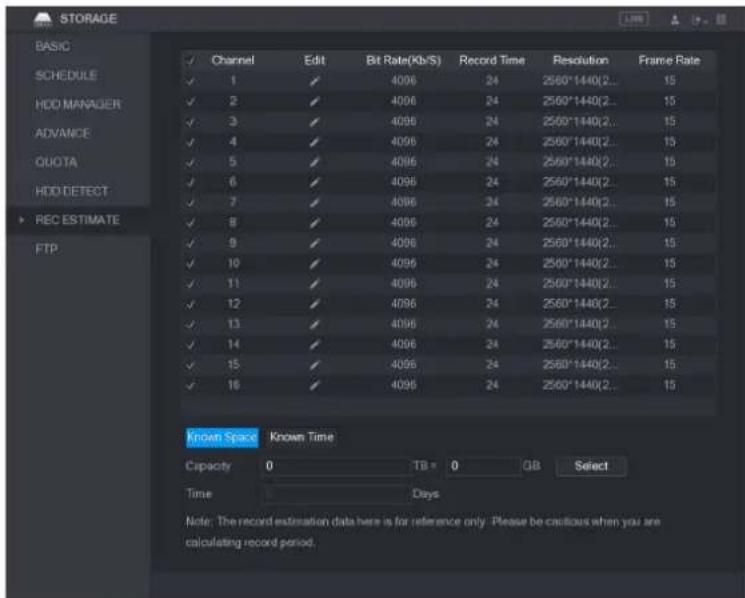
text_image
STORAGE BASIC ✓ Channel Edit Bit Rate(Kb/S) Record Time Resolution Frame Rate ✓ 1 ✓ 4096 24 2560*1440(2.. 15 ✓ 2 ✓ 4096 24 2560*1440(2.. 15 ✓ 3 ✓ 4096 24 2560*1440(2.. 15 ✓ 4 ✓ 4096 24 2560*1440(2.. 15 ✓ 5 ✓ 4096 24 2560*1440(2.. 15 ✓ 6 ✓ 4096 24 2560*1440(2.. 15 ✓ 7 ✓ 4096 24 2560*1440(2.. 15 ✓ 8 ✓ 4096 24 2560*1440(2.. 15 ✓ 9 ✓ 4096 24 2560*1440(2.. 15 ✓ 10 ✓ 4096 24 2560*1440(2.. 15 ✓ 11 ✓ 4096 24 2560*1440(2.. 15 ✓ 12 ✓ 4096 24 2560*1440(2.. 15 ✓ 13 ✓ 4096 24 2560*1440(2.. 15 ✓ 14 ✓ 4096 24 2560*1440(2.. 15 ✓ 15 ✓ 4096 24 2560*1440(2.. 15 ✓ 16 ✓ 4096 24 2560*1440(2.. 15 Known Space Known Time Capacity TB = 0 GB Select Time Days Note: The record estimation data here is for reference only. Please be cautious when you are calculating record period.Step 2 Click

The Edit dialog box is displayed.
You can configure the resolution, frame rate, bit rate and record time for the selected channel.

text_image
Edit Channel 1 Resolution 2560*1440(2560x1440) Frame Rate 15 Bit Rate 4096 (32 - 6144)Kb/S Record Time 24 h Copy OK BackStep 3 Click OK to save the settings.
Then the system will calculate the time period that can be used for storage according to the channels settings and HDD capacity.

NOTE
Click Copy to copy the settings to other channels.
Calculating Recording Time
Step 1 On the REC ESTIMATE interface, click the Known Space tab.
The Known Space interface is displayed.

text_image
Known Space Known Time Capacity 0 TB = 0 GB Select Time 0 Days Note: The record estimation data here is for reference only. Please be cautious when you are calculating record period.Step 2 Click Select.
The Select HDD(s) interface is displayed.
Step 3 Select the check box of the HDD that you want to calculate.
In the Known Space tab, in the Time box, the recording time is displayed.

text_image
Known Space Known Time Capacity 7 TB = 7000 GB Select Time Days Note: The record estimation data here is for reference only. Please be cautious when you are calculating record period.Calculating HDD Capacity for Storage
Step 1 On the REC ESTIMATE interface, click the Known Time tab. The Known Time interface is displayed.

text_image
Known Space Known Time Time 0 Days Capacity TB = GB Note: The record estimation data here is for reference only. Please be cautious when you are calculating record period.Step 2 In the Time box, enter the time period that you want to record. In the Capacity box, the required HDD capacity is displayed.

text_image
Known Space Known Time Time 22 Days Capacity 15.421 TB = 1700.1 GB Note: The record estimation data here is for reference only. Please be cautious when you are calculating record period.Configuring FTP Storage Settings
You can store and view the recorded videos and snapshots on the FTP server.
Preparation for Configuration
Purchase or download a FTP server and install it on your PC.
NOTE
For the created FTP user, you need to set the write permission; otherwise the upload of recorded videos and snapshots will be failed.
Configuration Steps
Step 1 Select Main Menu > STORAGE > FTP.
The FTP interface is displayed.
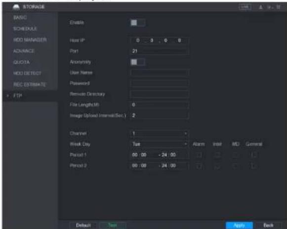
text_image
STORAGE BASIC SCHEDULE HDD MANAGER ADVANCE QUOTA HDD DETECT REC ESTIMATE FTP Enable Host IP 0 0 0 0 Port 21 Anonymity User Name Password Remote Directory File Length(M) 0 Image Upload Interval(Sec.) 2 Channel 1 Risk City Tue Alarm Intel MD General Period 1 00:00 -24:00 Period 2 00:00 -24:00 Default Text Apply BackStep 2 Configure the settings for the FTP settings parameters.
| Parameter | Description |
| Enable | Enable the FTP upload function. |
| Host IP | IP address of the PC that is installed with FTP server. |
| Port | The default is 21. |
| Anonymity | Enter the user name and password to login the FTP server. |
| User Name | Enable the anonymity function, and then you can login anonymously without entering the user name and password. |
| Password | |
| Remote Directory | Create folder on FTP server.If you do not enter the name of remote directory, system automatically creates the folders according to the IP and time.If you enter the name of remote directory, the system creates the folder with the entered name under the FTP root directory first, and then automatically creates the folders according to the IP and time. |
| File Length(M) | Enter the length of the uploaded recorded video.If the entered length is less than the recorded video length, only a section of the recorded video can be uploaded.If the entered length is more than the recorded video length, the whole recorded video can be uploaded.If the entered length is 0, the whole recorded video will be uploaded. |
| Image Upload Interval (Sec.) | ● If this interval is longer than snapshot interval, the system takes the recent snapshot to upload. For example, the interval is 5 seconds, and snapshot interval is 2 seconds per snapshot, the system uploads the recent snapshot every 5 seconds.● If this interval is shorter than snapshot interval, the system uploads the snapshot per the snapshot interval. For example, the interval is 5 seconds, and snapshot interval is 10 seconds per snapshot, the system uploads the snapshot every 10 seconds.● To configure the snapshot interval, selectMain Menu > CAMERA > ENCODE > Snapshot. |
| Channel | Select the channel that you want to apply the FTP settings. |
| Week Day | Select the week day and set the time period that you want to upload the recorded files. You can set two periods for each week day. |
| Period 1, Period 2 | |
| Record type | Select the record type (Alarm, Intel, MD, and General) that you want to upload. The selected record type will be uploaded during the configured time period. |
Step 3 Click Test.
The system pops up a message to indicate success or failure. If failed, please check the network connection or configurations.
Step 4 Click Apply to complete the settings.
Configuring System Settings
Configuring General System Settings
You can configure the device basic settings, time settings, and holiday settings.
To configure the holiday settings, do the following:
Step 1 Select Main Menu > GENERAL > Holiday.
The Holiday interface is displayed.
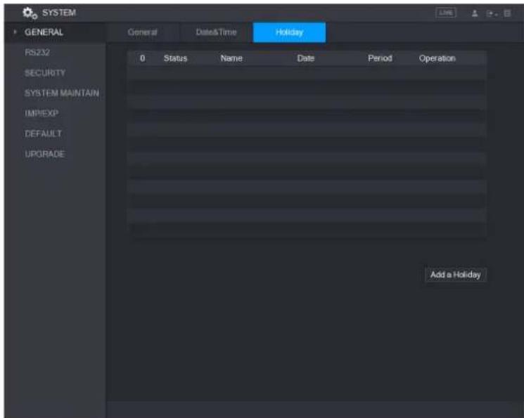
text_image
SYSTEM GENERAL PS232 SECURITY SYSTEM MAINTAIN IMPIEXP DEFAULT UPGRADE Date&Time Holiday 0 Status Name Date Period Operation Add a HolidayStep 2 Click Add a Holiday.
The Add a Holiday interface is displayed.

text_image
Add a Holiday Holiday Name Repeat Mode Once Always Holiday Range Date Week Start Time 2017 - 11 - 09 End Time 2017 - 11 - 09 Add More Add CancelStep 3 Configure the holiday name, repeat mode, time range according to your actual situation.
Step 4 Click Add.
The added holiday information is displayed.

NOTE
Enable the Add More function, so you can continue adding holiday information.
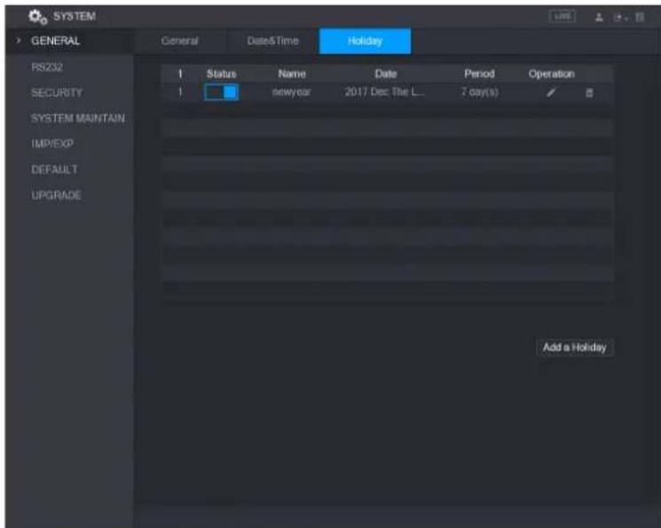
text_image
SYSTEM GENERAL General Date&Time Holiday RS232 SECURITY SYSTEM MAINTAIN IMP/EXP DEFAULT UPGRADE Status Name Date Period Operation newyear 2017 Dec The L... 7 day(s) Add a HolidayConfiguring Security Settings
To ensure the network security and protect data, you can configure the access permission to the Device from host IP (host IP means the PC or server that has an IP).
- White list includes the host IP that are permitted to access the Device.
- Back list includes the host IP that are not permitted to access the Device.
- Update time white list includes the host IP that are permitted to sync the Device time.
Configuring Access Right
Step 1 Select Main Menu > SYSTEM > SECURITY > Access Right.
The Access Right interface is displayed.
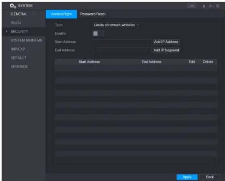
text_image
SYSTEM GENERAL RS232 SECURITY SYSTEM MAINTAIN IMPIEXP DEFAULT UPGRADE Access Right Password Reset Type Limits of network whitelist Enable Start Address Add IP Address End Address Add IP Segment Start Address End Address Edit Delete Apply BackStep 2 Configure the settings for the security parameters.
| Parameter | Description |
| Type | In the Type list, you can select Limits of network-whitelist, Limits of network-blacklist, or Updata time-whitelist. |
| Enable | Enable the security settings. |
| Start Address | Enter a single IP address or a start IP address of a network segment. |
| Add IP Address | Click Add IP Address to add a single IP address. |
| End Address | Enter the end IP address of a network segment. |
| Add IP Segment | Click Add IP Segment to add the IP addresses from the start IP through the end IP. Ⓞ NOTEThe system supports up to 64 IP addresses. |
Step 3 Click Apply to complete the settings.
Enabling Password Reset
Select Main Menu > SYSTEM > SECURITY > Password Reset, the Password Reset interface is displayed. The Enable check box is selected by default.

CAUTION
If you clear the Enable check box, you can only use the security questions to reset the password. Make sure you have set the security questions before clearing the check box.

text_image
SYSTEM GENERAL Pricing SECURITY SUSIN/MARTEN IM/EXP DEFAULT UPPGND Access Right Powered Press Enable Apply BackConfiguring System Maintenance Settings
When the Device has been running for a long time, you can configure the auto reboot when the Device is not working. You can also configure the case fan mode to reduce noise and extend the service life.
Step 1 Select Main Menu > SYSTEM > SYSTEM MAINTAIN
The SYSTEM MAINTAIN interface is displayed.
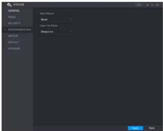
text_image
SYSTEM GENERAL RESID SECURITY SYSTEM MOUNTAIN IMPEXP DEFAULT UNIVADO Auto Reboot Never Case For Mode Always run Appo BackStep 2 Configure the settings for the system maintenance parameters.
| Parameter | Description |
| Auto Reboot | In the Auto Reboot list, select the reboot time. |
| Case Fan Mode | In the Case Fan Mode list, you can select Always run or Auto. If you select Auto, the case fan will stop or start according to the external conditions such as the Device temperature. [IMAGE]NOTENot all models support this function, and it is only supported on the local configuration interface. |
Step 3 Click Apply to complete the settings.
Exporting and Importing System Settings
You can export or import the Device system settings if there are several Devices that require the same setup.
NOTE
- The IMP/EXP interface cannot be opened if the backup operation is ongoing on the other interfaces.
- When you open the IMP/EXP interface, the system refreshes the devices and sets the current directory as the first root directory.
- Click Format to format the USB storage device.
Exporting System Settings
Step 1 Select Main Menu > SYSTEM > IMP/EXP.
The IMP/EXP interface is displayed.

text_image
SYSTEM GENERAL RS232 SECURITY SYSTEM MAINTAIN IMP/EXP DEFAULT UPGRADE Device Name Total Space Free Space Address Name Size Type Delete New Folder Import ExportStep 2 Insert a USB storage device into one of the USB ports on the Device.
Step 3 Click Refresh to refresh the interface.
The connected USB storage device is displayed.

text_image
SYSTEM GENERAL RS232 SECURITY SYSTEM MAINTAIN IMP/EXP DEFAULT UPGRADE Device Name sdb5(USB DISK) Refresh Format Total Space 15.60 GB Free Space 15.41 GB Address Name Size Type Delete IP Folder # FSu6016U Folder # IVSS Folder # RemoteConfig_20171103141044.csv 404 B File # printf_20171105172349.txt 451.3 KB File # kmsg_printf_20171105172349.txt 14.9 KB File # LAN1-20171107135215.pcap 1.18 MB File # LAN1-20171109135008.pcap 9.18 MB File # softmusic.mp3 2.14 MB File # lemontree.mp3 6.66 MB File # VID_20171105_135734.mp4 43.60 MB File # printf_20171113101348.txt 30.29 MB File # IP.PTZ Camera_20171116100220_201711... 527.2 KB File # printf_20171117110546.txt 19.91 MB File # kmsg_printf_20171117110546.txt 14.8 KB File # New Folder Import ExportStep 4 Click Export.
There is a folder under the name style of "Config_[YYYYMMDDhhmmss)". Double-click this folder to view the backup files.
Importing System Settings
Step 1 Insert a USB storage device containing the exported configuration files from another Device) into one of the USB ports on the Device.
Step 2 Select Main Menu > SYSTEM > IMP/EXP.
The IMP/EXP interface is displayed.
Step 3 Click Refresh to refresh the interface.
The connected USB storage device is displayed.
Step 4 Click on the configuration folder (under the name style of "Config_[YYYYMMDDhhmmss]") that you want to import.
Step 5 Click Import.
The Device will reboot after the imported is succeeded.
Restoring Default Settings

NOTE
Only Admin account supports this function.
You can select the settings that you want to restore to the factory default.
Step 1 Select Main Menu > SYSTEM > DEFAULT.
The DEFAULT interface is displayed.
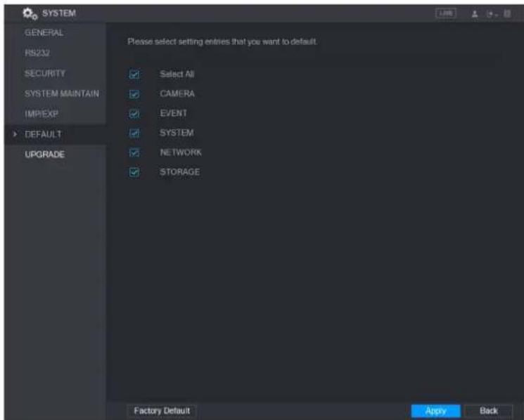
text_image
SYSTEM GENERAL RS232 SECURITY SYSTEM MAINTAIN IMPEXP DEFAULT UPGRADE Please select setting entries that you want to default. Select All CAMERA EVENT SYSTEM NETWORK STORAGE Factory Default Apply BackStep 2 Restore the settings.
- Select the settings that you want to restore, and then click Apply. The system starts restoring the selected settings.
- Click Factory Default, and then click OK. The system starts restoring the whole settings.
Upgrading the Device
Upgrading File
Step 1 Insert a USB storage device containing the upgrade files into the USB port of the Device.
Step 2 Select Main Menu > SYSTEM > UPGRADE.
The UPGRADE interface is displayed.
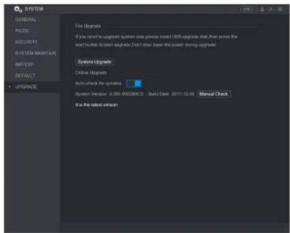
text_image
SYSTEM GENERAL RIS230 SECURITY SYSTEM MAINTAIN IMPORT DEFAULT • UPGRADE File Upgrade If you need to upgrade system now please insert USB upgrade that, then press the start button to start upgrade. Don't shut down the power during upgrade Systems Upgrade Online Upgrade Auto-check for updates System Version: 4.000.000000.0 Build Date: 2017-12-06 Manual Check It is the latest versionStep 3 Click System Upgrade.
The System Upgrade interface is displayed.

text_image
System Upgrade Device Name:sdb5(USB DISK) Refresh Total Space 15.60 GB Free Space 15.60 GB Address / Name Size Type Delete IP Folder # RemoteConfig_20171103141644.csv 464 B File # printf_20171105172349.txt 451.3 KB File # kmsg_print_20171105172349.txt 14.9 KB File # LAN1-20171107135215.pcap 1.18 MB File # Update File Start BackStep 4 Click the file that you want to upgrade.
The selected file is displayed in the Update File box.
Step 5 Click Start.
Performing Online Upgrade
When the Device is connected to Internet, you can use online upgrade function to upgrade the system.
Before using this function, you need to check if there is any new version by auto check or manual check.
• Auto check: The Device checks if there is any new version available at intervals.
- Manual check: Perform real-time check if there is any new version available.

CAUTION
Ensure the correct power supply and network connection during upgrading; otherwise the upgrading might be failed.
Step 1 Select Main Menu > SYSTEM > UPGRADE.
The UPGRADE interface is displayed.
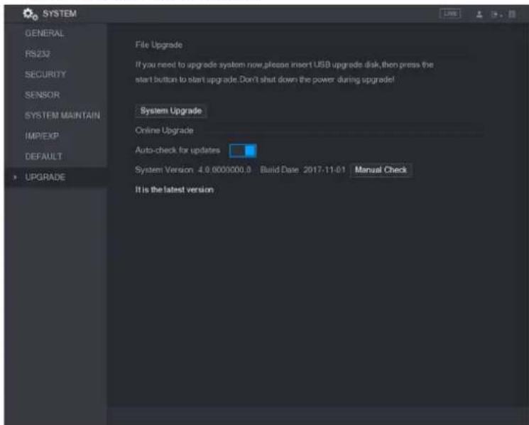
text_image
SYSTEM GENERAL RS232 SECURITY SENSOR SYSTEM MAINTAIN IMP/EXP DEFAULT UPGRADE File Upgrade If you need to upgrade system now,please insert USB upgrade disk, then press the start button to start upgrade. Don't shut down the power during upgrade! System Upgrade Online Upgrade Auto-check for updates System Version 4.0.0000000.0 Build Date 2017-11-01 Manual Check It is the latest versionStep 2 Check if there is any new version available.
• Auto check: Enable Auto-check for updates.
- Manual check: Click Manual Check.
The system starts checking the new versions. After checking is completed, the check result is displayed.
- If the "It is the latest version" text is displayed, you do not need to upgrade.
• If the text indicating there is a new version, please go the step 3.

text_image
SYSTEM CONTENTS PRICE DATA/FY SENSOR software/insurance download DEFAULT • Upgrade New System Upgrade Auto check for updates System version: 2.016 software, 3.045 data, 2017-11-08 New/Close Functional version: 2016-000000 - 1 device bus 2017-11-08 New System Information Upgrade NowViewing Information
You can view the information such as log information, HDD information, and version details
Viewing Version Details
You can view the version details such as device model, system version, and build date.
Select Main Menu > INFO > VERSION, the VERSION interface is displayed.
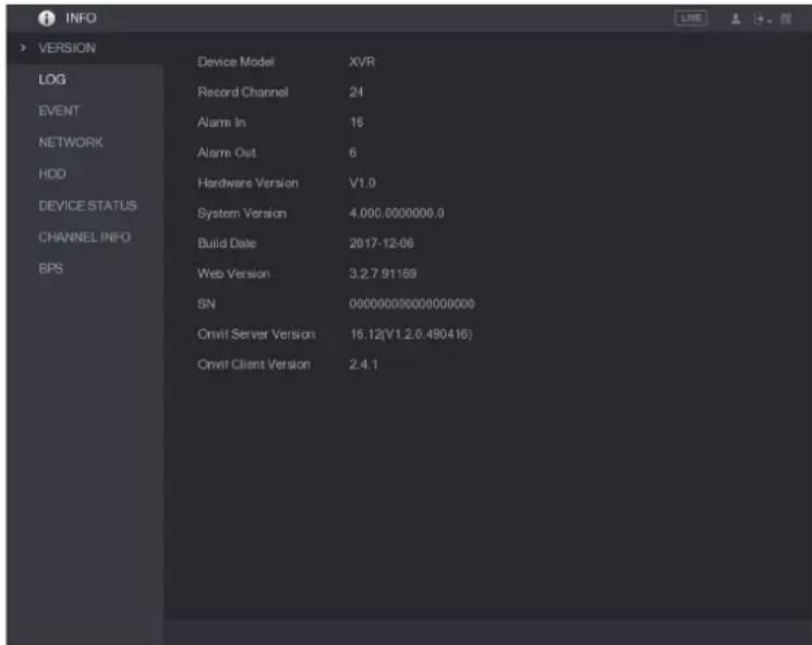
text_image
INFO > VERSION LOG EVENT NETWORK HDD DEVICE STATUS CHANNEL INFO BPS Device Model XVR Record Channel 24 Alarm In 16 Alarm Out 6 Hardware Version V1.0 System Version 4.000.0000000.0 Build Date 2017-12-06 Web Version 3.2.7.91169 SN 000000000000000000 Onvif Server Version 16.12(V1.2.0.490416) Onvif Client Version 2.4.1Viewing Log Information
You can view and search the log information.

NOTE
- If there is no HDD installed, the system can save up to 10,000 logs.
- If there is HDD installed and has been formatted, the system can save up to 500,000 logs.
- If there is HDD installed, the logs about system operations are saved in the memory of the Device and other types of logs are saved into the HDD. If there is no HDD installed, the other types of logs are also saved in the memory of the Device.
- When formatting the HDD, the logs will not be lost. However, if you take out the HDD from the Device, the logs might be lost.
Step 1 Select Main Menu > INFO > LOG, the LOG interface is displayed.
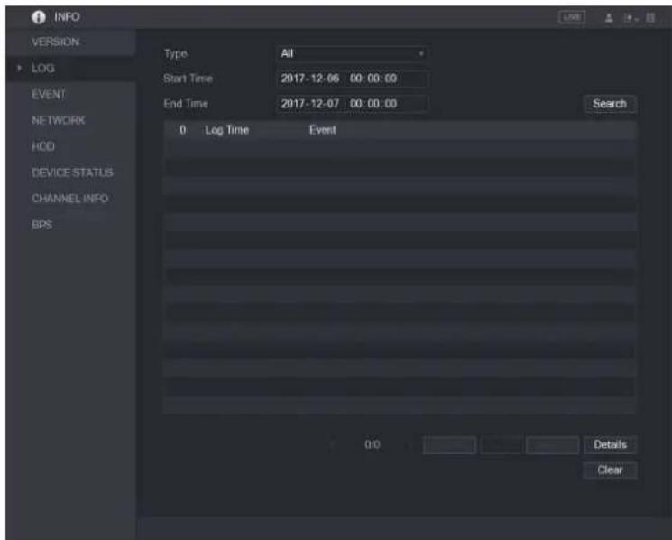
text_image
INFO VERSION LOG EVENT NETWORK HOD DEVICE STATUS CHANNEL INFO BPS Type All Start Time 2017-12-06 00:00:00 End Time 2017-12-07 00:00:00 Search 0 Log Time Event Details ClearStep 2 In the Type list, select the log type that you want to view (System, Config, Storage,
Record, Account, Clear, Playback, and Connection) or select All to view all logs.
Step 3 In the Start Time box and End Time box, enter the time period to search, and then click Search.
The search results are displayed.
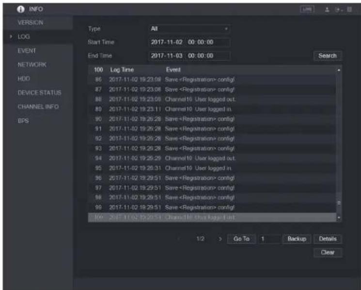
text_image
INFO VERSION LOG EVENT NETWORK HDD DEVICE STATUS CHANNEL INFO BPS Type All Start Time 2017-11-02 00:00:00 End Time 2017-11-03 00:00:00 100 Log Time Event 86 2017-11-02 19:23:08 Save
NOTE
- Click Details or double-click the log that you want to view, the Detailed Information interface is displayed. Click Next or Previous to view more log information.
- Click Backup to back up the logs into the USB storage device.
- Click Clear to remove all logs.
Viewing Event Information
You can view the event information of the Device and channel.
Select Main Menu > INFO > EVENT, the EVENT interface is displayed.
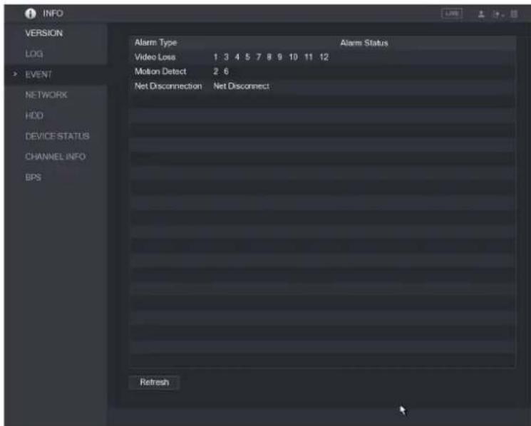
text_image
INFO VERSION LOG EVENT NETWORK HDD DEVICE STATUS CHANNEL INFO BPS Alarm Type Video Loss 1 3 4 5 7 8 9 10 11 12 Motion Detect 2 6 Net Disconnection Net Disconnect Alarm Status RefreshViewing Network Information
You can view the online users, network data transmission details, and test network.
Viewing Online Users
You can view the online user information and block any user for a period of time.
Select Main Menu > INFO > NETWORK > Online users, the Online users interface is displayed.

text_image
INFO VERSION LOG EVENT NETWORK HDD DEVICE STATUS CHANNEL INFO BPS Online User Network Load Network Test User Name IP User Login Time Block 00:00 182.368.12.191 APP 15.00.191.191.191.191.191.191.191.191.191.191.191.191.191.191.191.191.191.191.191.191.191.191.191.191.191.19 Block 40 SecTo block an online user, click and then enter the time that you want to block this user.
The maximum value you can set is 65535.
The system detects every 5 seconds to check if there is any user added or deleted, and update the user list timely.
Vewing the Network Load
Network load means the data flow which measures the transmission capability. You can view the information such as data receiving speed and sending speed.
Step 1 Select Main Menu > INFO > NETWORK > Network Load.
The Network Load interface is displayed.
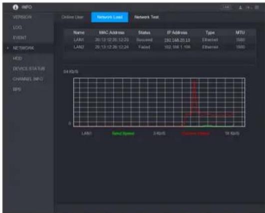
text_image
INFO VEREOS LOG EVENT NETWORK HDD DEVICE STATUS CHANNEL INFO BPS Online User Network Load Network Test Name MAC Address Status IP Address Type MTU LAN1 26.13.12.26.12.23 Syscinel 192.168.20.13 Ethernet 1500 LAN2 26.13.12.26.12.24 Tailed 192.168.1.156 Ethernet 1500 54 kHz LAN1 Says Name 2 kHz Current Events 54 kHzStep 2 Click the LAN name that you want to view, for example, LAN1.
The system displays the information of data sending speed and receiving speed.

NOTE
- The default display is LAN1 load.
- Only one LAN load can be displayed at one time.
Viewing HDD Information
You can view the HDD quantity, HDD type, total space, free space, status, and S.M.A.R.T information.
Select Main Menu > INFO > HDD, the HDD interface is displayed.
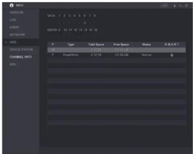
text_image
INFO VERSION SATA 1 2 3 4 5 6 7 8 LOG EVENT ESATA 0 10 11 12 13 14 15 16 NETWORK HDD DEVICE STATUS CHANNEL INFO GPS Type Total Space Free Space Status S.M.A.R.T KB 2.72 TB 175.00 GB Read/Write 2.72 TB 175.00 GB Normal| Parameter | Description |
| SATA | Indicates the quantity of HDD that can be installed. The total quantity is different depending on the model you purchased.●: HDD is in normal working status.●:-: No HDD is installed. |
| No. | Indicates the number of the currently connected HDD. * means the current working HDD. |
| Type | Indicates HDD type. |
| Total Space | Indicates the total capacity of HDD. |
| Free Space | Indicates the usable capacity of HDD. |
| Status | Indicates the status of the HDD to show if it is working normally. |
| S.M.A.R.T | View the S.M.A.R.T reports from HDD detecting. |
Viewing Device Status
You can view the information such as CPU temperature and memory usage to know the device status.
Select Main Menu > INFO > DEVICE STATUS, the DEVICE STATUS interface is displayed.
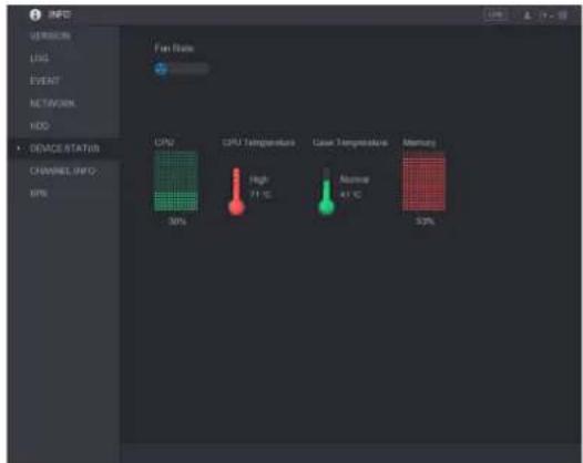
text_image
INFO VEREOS LOG EVENT NETWORK HDD DEVICE STATUS CHANNEL INFO EPS Fan Rate CPU CPU Temperature High 71 °C Case Temperature 41 °C Memory 30% 53%Viewing Channel Information
You can view the camera information connected to each channel.
Select Main Menu > INFO > CHANNEL INFO, the CHANNEL INFO interface is displayed.

text_image
INFO VERSION LOG Extract NETWORK HDD DEVICE STATUS CHANNEL INFO EPS Channel Format 1 2 1000V 3 - 4 - 5 - 6 - 7 - 8 1000V 9 - 10 - 11 - 12 -Viewing Data Stream Information
You can view the real-time data stream rate and resolution of each channel.
Select Main Menu > INFO > BPS, the BPS interface is displayed.
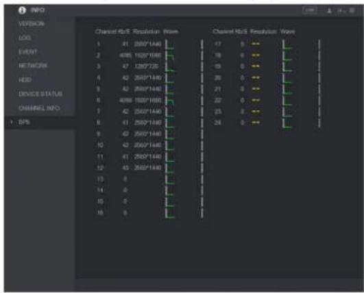
bar
| Category | Channel NoS Resolution Rate | |---|---| | LOG | 41 (280*1440) | | EVENT | 4085 (1920*1666) | | NETWORK | 47 (280*728) | | HSD | 42 (280*1440) | | DEVICE STATUS | 43 (280*1440) | | CHANNEL INFO | 4088 (280*1666) | | EPS | 42 (280*1440) | | | 41 (280*1440) | | | 42 (280*1440) | | | 41 (280*1440) | | | 43 (280*1440) | | | 0 | | | 0 | | | 0 | | | 0 | | | 0 |Logout the Device
On the top right of the Main Menu interface or on any interface after you have entered the
Main Menu, click
- Select Logout, you will log out the device.
- Select Reboot, the Device will be rebooted.
Select Shutdown, the Device will be turned off.