AEL18DX - Fridge GE - Free user manual and instructions
Find the device manual for free AEL18DX GE in PDF.

User questions about AEL18DX GE
0 question about this device. Answer the ones you know or ask your own.
Ask a new question about this device
Download the instructions for your Fridge in PDF format for free! Find your manual AEL18DX - GE and take your electronic device back in hand. On this page are published all the documents necessary for the use of your device. AEL18DX by GE.
USER MANUAL AEL18DX GE
SAFETY INFORMATION .... 3
USING THE AIR CONDITIONER
Controls 4
CARE AND CLEANING
Air Filter 7
Outdoor Coils 7
INSTALLATION
INSTRUCTIONS......8
TROUBLESHOOTING TIPS ..... 16
Normal Operating Sounds ....16
CONSUMER SUPPORT
Warranty 17
Consumer Support 18
Write the model and serial numbers here:
Model # ____
Serial # ____
You can find the rating label on the side of the air conditioner.
OWNER'S MANUAL & INSTALLATION INSTRUCTIONS
AEL14
AEL18
THANK YOU FOR MAKING GE APPLIANCES A PART OF YOUR HOME.
Whether you grew up with GE Appliances, or this is your first, we're happy to have you in the family.
We take pride in the craftsmanship, innovation and design that goes into every GE Appliances product, and we think you will too. Among other things, registration of your appliance ensures that we can deliver important product information and warranty details when you need them.
Register your GE appliance now online. Helpful websites and phone numbers are available in the Consumer Support section of this Owner's Manual. You may also mail in the pre-printed registration card included in the packing material.

GE APPLIANCES
IMPORTANT SAFETY INFORMATION READ ALL INSTRUCTIONS BEFORE USING THE APPLIANCE
WARNING
For your safety, the information in this manual must be followed to minimize the risk of shock or personal injury.
■ Use this appliance only for its intended purpose as described in this Owner's Manual.
■ This air conditioner must be properly installed in accordance with the Installation Instructions before it is used.
■ Never unplug your air conditioner by pulling on the power cord. Always grip plug firmly and pull straight out from the receptacle.
- Replace immediately all electric service cords that have become frayed or otherwise damaged. A damaged power supply cord must be replaced with a new power supply cord obtained from the manufacturer and not repaired. Do not use a cord that shows cracks or abrasion damage along its length or at either the plug or connector end.
■ Turn the unit OFF and unplug your air conditioner before cleaning.
■ GE Appliances does not support any servicing of the air conditioner. We strongly recommend that you do not attempt to service the air conditioner yourself.
■ For your safety...do not store or use combustible materials, gasoline or other flammable vapors or liquids in the vicinity of this or any other appliance.
■ All air conditioners contain refrigerants, which under federal law must be removed prior to product disposal. If you are getting rid of an old product with refrigerants, check with the company handling disposal about what to do.
■ If the receptacle does not match the plug, the receptacle must be changed out by a qualified electrician.
■ These R410A air conditioning systems require contractors and technicians to use tools, equipment and safety standards approved for use with this refrigerant. DO NOT use equipment certified for R22 refrigerant only.
WARNING
USE OF EXTENSION CORDS
RISK OF FIRE. Could cause serious injury or death.
■ DO NOT use an extension cord with this Window Air Conditioner.
■ DO NOT use surge protectors or multi-outlet adaptors with this Window Air Conditioner.
HOW TO CONNECT ELECTRICITY
Do not, under any circumstances, cut or remove the third (ground) prong from the power cord. For personal safety, this appliance must be properly grounded.
DO NOT use an adapter plug with this appliance.
The power cord of this appliance is equipped with a 3-prong (grounding) plug which mates with a standard 3-prong (grounding) wall outlet to minimize the possibility of electric shock hazard from this appliance.
Power cord includes a current interrupter device. A test and reset button is provided on the plug case. The device should be tested on a periodic basis by first pressing the TEST button and then the RESET button while plugged into the outlet. If the TEST button does not trip or if the RESET button will not stay engaged, discontinue use of the air conditioner and contact a qualified service technician.
Have the wall outlet and circuit checked by a qualified electrician to make sure the outlet is properly grounded.
Where a 2-prong wall outlet is encountered, it is your personal responsibility and obligation to have it replaced with a properly grounded 3-prong wall outlet.
The air conditioner should always be plugged into its own individual electrical outlet which has a voltage rating that matches the rating plate.
This provides the best performance and also prevents overloading house wiring circuits which could cause a fire hazard from overheated wires.
See the Installation Instructions, Electrical Requirements section for specific electrical connection requirements.
READ AND SAVE THESE INSTRUCTIONS
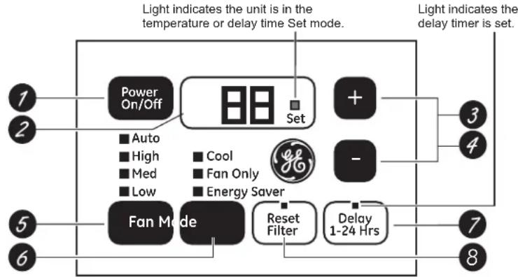
Controls
Features and appearance will vary.
Lights below the touch pads on the air conditioner control panel indicate the selected settings.
flowchart
graph TD
    A["Power On/Off"] --> B["Set"]
    B --> C["+"]
    C --> D["3"]
    C --> E["4"]
    F["Fan Mode"] --> G["Reset Filter"]
    G --> H["Delay 1-24 Hrs"]
    H --> I["7"]
    H --> J["8"]
    K["Light indicates the unit is in the temperature or delay time Set mode."] --> B
    L["Light indicates the delay timer is set."] --> C
    M["Auto"] --> N["■ Auto"]
    O["High"] --> P["■ High"]
    Q["Med"] --> R["■ Med"]
    S["Low"] --> T["■ Low"]
    U["Cool"] --> V["■ Cool"]
    W["Fan Only"] --> X["■ Fan Only"]
    Y["Energy Saver"] --> Z["■ Energy Saver"]
NOTE: The display always shows the room temperature except when setting the Set temperature or the Delay timer.
Air Conditioner Controls
text_image
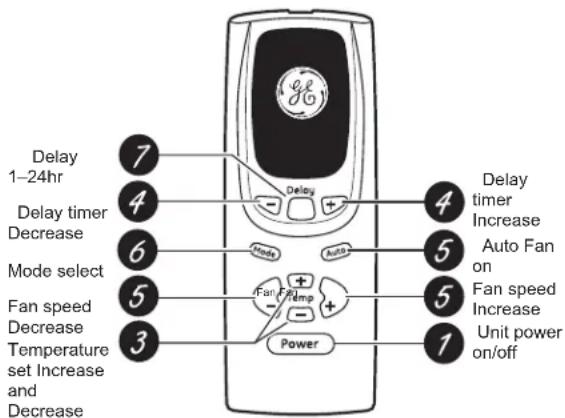
Delay 1-24hr Delay timer Decrease Mode select Fan speed Decrease Temperature set Increase and Decrease 7 4 6 5 3 Delay + - Temp + - Power 4 Auto Fan on Fan speed Increase Unit power on/off 1 5 5 4 Delay timer IncreaseRemote Control
Controls
1. Power Pad
Turns air conditioner on and off. When turned on, the display will show the room temperature.
2. Display
Shows the room temperature or time remaining on the Delay timer. Shows the Set temperature while setting the temperature in Cool or Energy Saver modes.
3. Temp Increase + /Decrease - Pads
Use to set temperature when in Cool or Energy Saver mode. The Set light will turn on while setting..
4. Delay Increase + /Decrease - Pads
Each touch of the Increase ▲ / Decrease ▼ pads on the unit or the Increase + / Decrease – pads on the remote control will set the delay time when using the Delay 1–24hr timer. The Set light will turn on while setting.
5. Fan Speed Pad
Use to set the fan speed to Low, Med, High or Auto on the unit. NOTE: On the remote control, use the fan speed Increase + / Decrease – pads to set the fan speeds to Low, Med or High. Use the Auto pad to turn Auto fan on.
6. Mode Pad
Use to set the air conditioner to Cool, Energy Saver or Fan Only mode.
7. Blay Pad
Delay ON—When the air conditioner is off, it can be set to automatically come on in 1 to 24 hours at its previous mode and fan settings.
Delay OFF—When the air conditioner is on, it can be set to automatically turn off in 1 to 24 hours.
How to set:
Press the Delay 1–24hr pad on the unit or the Delay pad on the remote control. Each touch of the Increase ▲ / Decrease ▼ pads on the unit or the Increase + / Decrease – pads on the remote control will set the timer in 1-hour intervals. The Set light will turn on while setting.
To review the remaining time on the Delay 1–24hr timer, press the Delay 1–24hr pad on the unit or the Delay pad on the remote control. Use the Increase ▲ / Decrease ▼ pads on the unit or the Increase + / Decrease – pads on the remote control to set a new time if desired.
To cancel the timer, press the Delay 1–24hr pad until the light on the Delay 1–24hr pad goes off.
8. Filter Reset Pad
LED will turn on when fan has accumulated 250 hours of run time as a reminder to clean filter. Press Reset Filter to turn off the LED and reset the accumulated run time.
Using the Air Conditioner
Do Not Operate in Freezing Outdoor Conditions
This cool-only air conditioner was not designed for freezing outdoor conditions. It must not be used when the outdoor temperature is below freezing (32°F).
Remote Control
■ To ensure proper operation, aim the remote control at the signal receiver on the air conditioner.
■ Make sure nothing is between the air conditioner and the remote control that could block the signal.
■ The remote control signal has a range of up to 20 feet.
■ Make sure batteries are fresh and installed correctly as indicated on the remote control.
■ Remote contains a magnet allowing it to attach to metal surfaces.
Cool Mode
Use the Cool mode at Low, Med, High or Auto Fan Speed for cooling. Use the Temperature Increase ▲ / Decrease ▼ pads to set the desired temperature between 64°F and 86°F in 1°F increments.
An electronic thermostat is used to maintain the room temperature. The compressor will cycle on and off to keep the room at the set level of comfort. Set the thermostat at a lower number and the indoor air will become cooler. Set the thermostat at a higher number and the indoor air will become warmer.
NOTE: If the air conditioner is off and is then turned on while set to a Cool setting or if turned from a fan setting to a Cool setting, it may take approximately 3 minutes for the compressor to start and cooling to begin.
Cooling Descriptions
For Normal Cooling—Select the Cool mode and High or Med fan with a middle set temperature.
For Maximum Cooling—Select the Cool mode and High fan with a lower set temperature.
For Quieter and Nighttime Cooling—Select the Cool mode and Low fan with a middle set temperature.
Energy Saver Mode
This mode optimizes the cooling power of your air conditioner, thereby saving you energy. Once the set point temperature has been reached, the fan will cycle off to save energy. The fan will cycle back on periodically to insure all cooling capacity in the system is used. This mode is the default mode for the unit. Each time the unit is powered off, it will restart in Energy Saver mode ON. This includes Delay timer mode. The first time the unit is turned on, the settings will be 70° and Low fan. You can adjust the fan speed and temperature to your personal comfort.
ON—The fan will cycle on and off with the compressor. This may result in wider variations of room temperature and humidity. NOTE: the fan may continue to run for a short time or may pulse intermittently after the compressor cycles off to sample the room air.
OFF—The fan runs all the time, while the compressor cycles on and off.
Using the Air Conditioner
Fan Only Mode
Use the Fan Only Mode at Low, Med or High fan speed to provide air circulation and filtering without cooling. Since fan-only settings do not provide cooling, a Set temperature cannot be entered. The room temperature will appear in the display.
NOTE: Auto Fan Speed cannot be used when in the Fan Only Mode.
Auto Fan Mode
Set to Auto fan speed for the fan speed to automatically set to the speed needed to provide optimum comfort settings with the set temperature.
If the room needs more cooling, the fan speed will automatically increase. If the room needs less cooling, the fan speed will automatically decrease.
NOTE: Auto Fan Speed cannot be used when in the Fan Only Mode.
Control Display On and Off
To reduce brightness during sleeping hours, this air conditioner control display has an automatic off feature where the control display will turn off completely after 2 minute of inactivity. To illuminate the control interface, press any button on the control display or remote control. The control display will illuminate all previously illuminated LED's. The control interface will now respond to any prescribed button press after it is illuminated.
Power Outage Recovery Feature
In the case of a power outage or interruption, the unit will automatically restart in the settings last used after the power is restored. If the Delay 1–24hr feature was set, it will resume countdown. You may need to set a new time if desired.
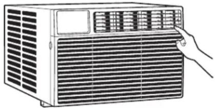
Air Direction
Use the lever to adjust the air direction left and right only.
natural_image
Line drawing of an electric air conditioner unit with ventilation grilles and a hand adjusting the grille (no text or symbols)Care and Cleaning
Grille and Case
Turn the air conditioner off and remove the plug from the wall outlet before cleaning.
To clean, use water and a mild detergent. Do not use bleach or abrasives.
Air Filter
The air filter behind the front grille should be checked and cleaned at least every 30 days or more often if necessary.
To remove:
Open the inlet grille by pulling downward on the tabs at the top upper corners of the inlet grille until the grille is in a 45° position. Remove the filter.
Clean the filter with warm, soapy water. Rinse and let the filter dry before replacing it. Do not clean the filter in a dishwasher.
CAUTION
DO NOT operate the air conditioner
without a filter because dirt and lint will clog it and reduce performance.

text_image
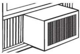
Tab TabOutdoor Coils
The coils on the outdoor side of the air conditioner should be checked regularly. If they are clogged with dirt or soot, they may be professionally cleaned.
natural_image
Simple line drawing of a cabinet with vertical bars on both sides (no text or symbols)How to Insert the Battery in the Remote Control
- Remove the battery cover by sliding it according to the arrow direction.
- Insert new batteries, making sure that the (+) and (−) of battery are installed correctly.
- Reattach the cover by sliding it back into position.
NOTES:
■ Use 2 "AAA" (1.5 volt) alkaline batteries. Do not use rechargeable batteries.
■ Remove the batteries from the remote control if the system is not going to be used for a long time.
■ Do not mix old and new batteries. Do not mix alkaline, standard (carbon-zinc) or rechargeable (ni-cad, ni-mh, etc) batteries.
Questions? Call 800.GE.CARES (800.432.2737) or Visit our Website at: GEAppliances.com
BEFORE YOU BEGIN
Read these instructions completely and carefully.
- IMPORTANT — Save these instructions for local inspector's use.
• IMPORTANT — Observe all governing codes and ordinances. - Note to Installer – Be sure to leave these instructions with the Consumer.
- Note to Consumer – Keep these instructions for future reference.
- Skill level – Installation of this appliance requires basic mechanical skills.
• Completion time – Approximately 1 hour
• We recommend that two people install this product. - Proper installation is the responsibility of the installer.
- Product failure due to improper installation is not covered under the Warranty.
- You MUST use all supplied parts and use proper installation procedures as described in these instructions when installing this air conditioner.
TOOLS YOU WILL NEED

natural_image
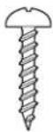
Line drawing of a screwdriver with a magnified view of the tip (no text or symbols)Phillips head screwdriver
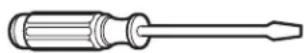
Flat-blade screwdriver

Ruler or tape measurePencil
Level

Scissors or knife
ELECTRICAL REQUIREMENTS

Some models require a 115/120-volt AC, 60-Hz grounded outlet protected with a 15-amp time-delay fuse or circuit breaker.
The 3-prong grounding plug minimizes the possibility of electric shock hazard. If the wall outlet you plan to use is only a 2-prong outlet, it is your responsibility to have it replaced with a properly grounded 3-prong wall outlet.

Some models require 230/208-volt AC, protected with a time-delay fuse or circuit breaker. These models should be installed on their own single branch circuit for best performance and to prevent overloading house or apartment wiring circuits, which could cause a possible fire hazard from overheating wires.

CAUTION
Do not, under any circumstances, cut or remove the third (ground) prong from the power cord.
Do not change the plug on the power cord of this air conditioner.
Aluminum house wiring may present special problems—consult a qualified electrician.
Power cord includes a current interrupter device. A test and reset button is provided on the plug case. The device should be tested on a periodic basis by first pressing the TEST button and then the RESET button while plugged into the outlet. If the TEST button does not trip or if the RESET button will not stay engaged, discontinue use of the air conditioner and contact a qualified service technician.
PARTS INCLUDED
(Appearance may vary)
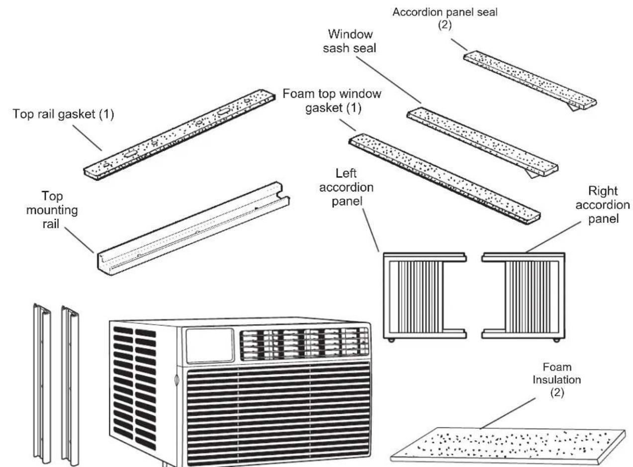
text_image
Top rail gasket (1) Top mounting rail Window sash seal Accordion panel seal (2) Foam top window gasket (1) Left accordion panel Right accordion panel Foam Insulation (2)Side rail (2)

V-supports (2)
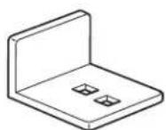
Sill angle bracket (2)

Window locking bracket (2)

Type A screws (10)
Type B screws (2)
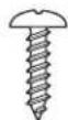
Type C screws (4)


Type E bolt with nut (4)


Type F bolt with nut (2)
Installation Instructions
1. WINDOW REQUIREMENTS
• These instructions are for a standard double-hung window. You will need to modify them for other types of windows.
- The air conditioner can be installed without the accordion panels if needed to fit in a narrow window. See the window opening dimensions.
- All supporting parts must be secured to firm wood, masonry or metal.
- The electrical outlet must be within reach of the power cord.
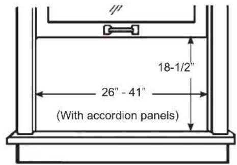
text_image
18-1/2" 26" - 41" (With accordion panels)2. STORM WINDOW REQUIREMENTS
A storm window frame will not allow the air conditioner to tilt toward the outside, and will keep it from draining properly. To adjust for this, attach a piece of wood to the sill.
WOOD PIECES
WIDTH: 2"
LENGTH: Long enough to fit inside the window frame.
THICKNESS: To determine the thickness, place a piece of wood on the sill to make it 1/2" higher than the top of the storm window frame or the vinyl frame.
Attach securely with nails or screws provided by the installer.
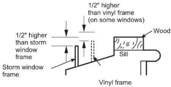
text_image
1/2" higher than vinyl frame (on some windows) 1/2" higher than storm window frame Storm window frame Wood Sill Vinyl frame3. PREPARE THE AIR CONDITIONER
A. Pull down the front panel and remove the filter. Remove the front panel by lifting up at an angle.
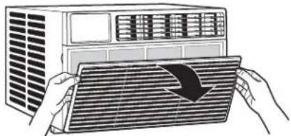
natural_image
Illustration of a car air conditioner unit with hands holding a grid fan (no text or symbols visible)B. Remove the four front screws. Save them for reinstalling the front housing.

natural_image
Illustration of a white electric air conditioner unit with ventilation grilles and ventilation grilles (no text or symbols)C. Grasp the lower corners of the grille while pressing in on the case sides with your finger tips. Pull out to release and lift it up.
NOTE: Do not pull the bottom edge toward you more than 3" or you may damage the tabs of the grille.
natural_image
Illustration of an air conditioner unit with ventilation grilles and heat sinks (no text or symbols)D. When the front grille is removed the control panel will still be attached by a harness. Turn the grille around so you can see the back side of the grille. Remove the 2 screws to separate the control panel housing from the grille. NOTE: Be sure to save these screws. You will need them later in the installation.

text_image
Remove Screws3. PREPARE THE AIR CONDITIONER (continues)
E. Remove the ground screw from the left side of the case. Keep it in a safe location. NOTE: Be sure to save this screw. You will need them later in the installation.

natural_image
Line drawing of a portable industrial machine with heat exchanger and ventilation slots (no text or symbols)F. Slide the air conditioner from the case by gripping the base pan handle and pulling forward while bracing the case. Do not pull or lift on the foam discharge area.

text_image
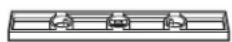
Do not pull or lift in this area—damage to the unit may result FRONT4. PREPARE THE CASE
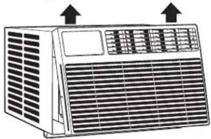
A. Attach the top rail gasket to the bottom of the top rail.

natural_image
Diagram of two rectangular objects with upward arrows indicating movement or force, no text or symbols presentB. Install the top mounting rail with 4 type A screws from the inside of the case. Press firmly to drive the screws into the gasket and through the top mounting rail.

text_image
Top mounting rail4. PREPARE THE CASE
C. Slide each side retainer onto the edge of each according panel. The figure shows the orientation of each accordion panel and side retainer assembly relative to the case from a top view of the unit.

text_image
SIDE RETAINER WINDOW FILLER PANEL SIDE RETAINER WINDOW FILLER PANEL
natural_image
Pure mechanical diagram showing two circular insets with cross-sectional views of a structural component (no text or symbols)D. Remove the backing from the accordion seal (two short strips). Stick one sealing strip respectively on the left side and right side of the accordion panels, as shown.
natural_image
Two hand-drawn diagrams showing a panel being held, with no text or symbols present.E. Slide the left and right accordion panels into the top and bottom mounting rails.
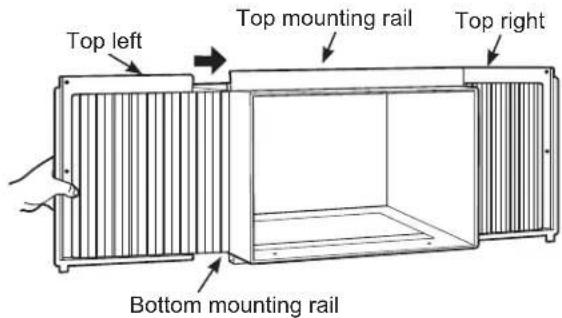
text_image
Top left Top mounting rail Top right Bottom mounting railF. Attach the side retainers to the case using 6 type A screws.
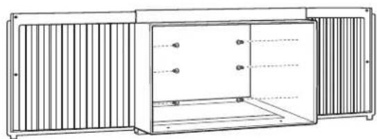
natural_image
Technical line drawing of a cabinet or enclosure with vertical slats and internal doors (no text or symbols)Installation Instructions
5. PREPARE THE WINDOW AND INSTALL THE CASE
A. Cut the window sash seal to the proper length. Peel off the backing and attach the seal to the underside of the window sash.
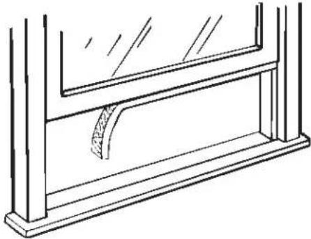
natural_image
Line drawing of a window frame structure with no text or symbolsB. Open the window and mark the center of the window sill.
C. Carefully slide the case into the window and center the case. Lower the window behind the top mounting rail. Pull the bottom of the case forward so that the bottom mounting rail is tight against the back of the window stool. Mount the case to the window sill using 2 type B screws. Drill pilot holes, if necessary.

text_image
Stool 2 type B screwsD. Assemble the V-support and V-support bracket with Type F nut and bolt

text_image
With Type F bolt and bolt Type E bolt and nut Left Right Sill angle bracket V-support Type F bolt and nut5. PREPARE THE WINDOW AND INSTALL THE CASE (continues)
E. Position the V-supports on the case bottom so that they will be near the outside wall. Attach a V-support to each side of the bottom of the case with Type E bolts, 2 for each support.
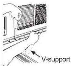
text_image
V-supportF. Adjust sill angle brackets to rest on sill.
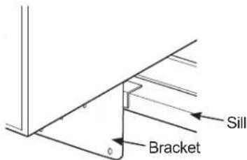
text_image
Sill BracketG. Extend the left and right accordion panels to the vertical window sashes. Drill pilot holes and attach the top corners with 2 type C screws.
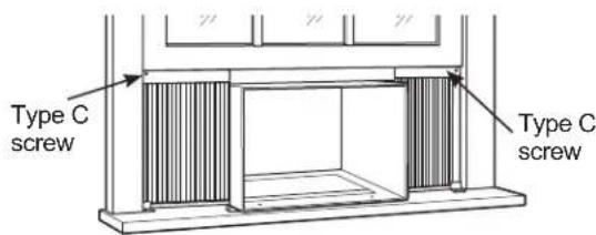
text_image
Type C screw Type C screw5. PREPARE THE WINDOW AND INSTALL THE CASE (continues)
Use Type B Screw to install the window lock bracket on top of the bottom window.
H.
CAUTION
To prevent broken glass or damage to windows, on vinyl or other similarly constructed windows, attach the window locking bracket to the window side jamb with one Type B screw.

text_image
Vinyl WoodI. Cut the foam top window gasket to the window width.
J. Stuff the foam between the glass and the window to prevent air and insects from getting into the room.

natural_image
Line drawing of hands holding a ruler over a book (no text or symbols)NOTE: If the gasket supplied does not fit your window, obtain appropriate material locally to provide a proper installation seal.
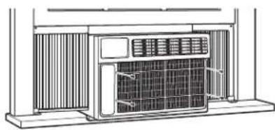
6. INSTALL THE AIR CONDITIONER IN THE CASE
A. Slide the air conditioner into the case by the base pan. Do not push on the controls, foam air discharge housing or the finned coils. Make sure the air conditioner is firmly seated.

text_image
Base PanDo not press on these areas—damage to the unit may result
Installation Instructions
6. INSTALL THE AIR CONDITIONER IN THE CASE (continues)
B. Replace the 1 screw removed earlier, one on each side of the case. IMPORTANT: THE GROUND SCREWS MUST BE REINSTALLED TO ENSURE PROPER GROUND.

natural_image
Line drawing of a cabinet or enclosure with a grid-patterned base and top panel (no text or symbols)C. Reinstall the control to the panel housing by replacing the 2 screws you removed earlier.

text_image
Install ScrewsD. Attach the front grille to the case by inserting the tabs on the grille into the slots on the front top of the case. Push the grille in.

text_image
Diagram showing a hand holding a tool interacting with a device, with an arrow indicating the process to press or install a brick wall.E. Replace the screws.
natural_image
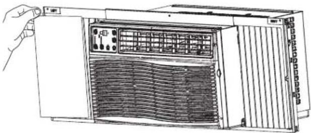
Technical line drawing of an air conditioner unit with cooling fins and ventilation grilles (no text or labels)F. Install the filter and the front grille.

natural_image
Illustration of a person opening a ventilation grille into a cabinet (no text or symbols visible)G. Plug in the air conditioner.
7. INSTALL FOAM INSULATION
Additional insulation is provided with your window air conditioner to reduce heat leakage into the home, reducing overall energy usage.
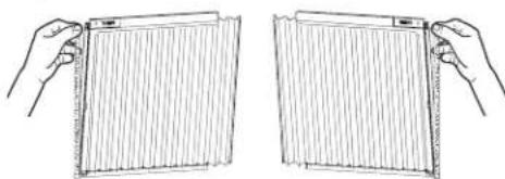
A. After the air conditioner is installed in the window measure the length of the accordion for both sides.

text_image
L1 L2 H HB. Cut the foam insulation to the measured length of the left and right side accordion. NOTE: Be sure to measure each accordion because the length could be different on each side.

text_image
L1 or L2C. Remove adhesive from back of foam insulation. Stick the foam insulation onto the left and right accordion, and inside of the frames.
natural_image
Line drawing of a computer rack unit with ventilation grilles and control panel (no text or symbols)NOTE: be careful to cover the entire accordion.
Through-the-Wall Installation Instructions—Optional
The case may be installed through-the-wall in both existing and new construction.
Read completely, then follow step-by-step.
NOTE: Obtain all materials locally for mounting the air conditioner through-the-wall.
1. IMPORTANT
Through-the-wall installation is not appropriate if any of the side or top louvers in the case will be obstructed by the wall.
All side and top louvers in the case must project on the outdoor side of the wall.
The room side of the case must project into the room far enough to maximize the balance of the unit.
The case must be installed level from side-to-side and with a slight tilt from front to rear. Use a level; no more than a 1/2 bubble will be the correct case slant to the outside.
Lintel angle is required to support bricks or blocks above opening.
Flashing is required and should extend the length of the opening to ensure no inside cavity leakage occurs.
A. Remove the air conditioner from the case. For specific instruction, refer to the Window Installation Instructions.
B. Make certain that a wall receptacle is available close to the hole location or make arrangements to install a receptacle.
natural_image
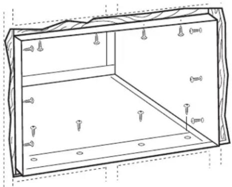
Technical line drawing of a rectangular enclosure with screws and mounting holes (no text or symbols)C. Place the case in the wall opening and place wood support strips between the case bottom and the flashing on both sides of the bottom rail. They should be the same height as the bottom rail and the same length as the wall opening.
1. IMPORTANT (cont.)
D. Secure with 14 wood screws anchored at least an inch into the wall support structure.
NOTE: Drill pilot holes, if necessary, for proper installation. If the frame is oversized, use shims to prevent case distortion.
2. FINISH THE WALL OPENING
A. Caulk all four sides on the outdoor side of the case to prevent moisture from getting through to the interior wall. Use of flashing (drip rail) will further prevent water from dripping inside the wall and down the outside of the building.
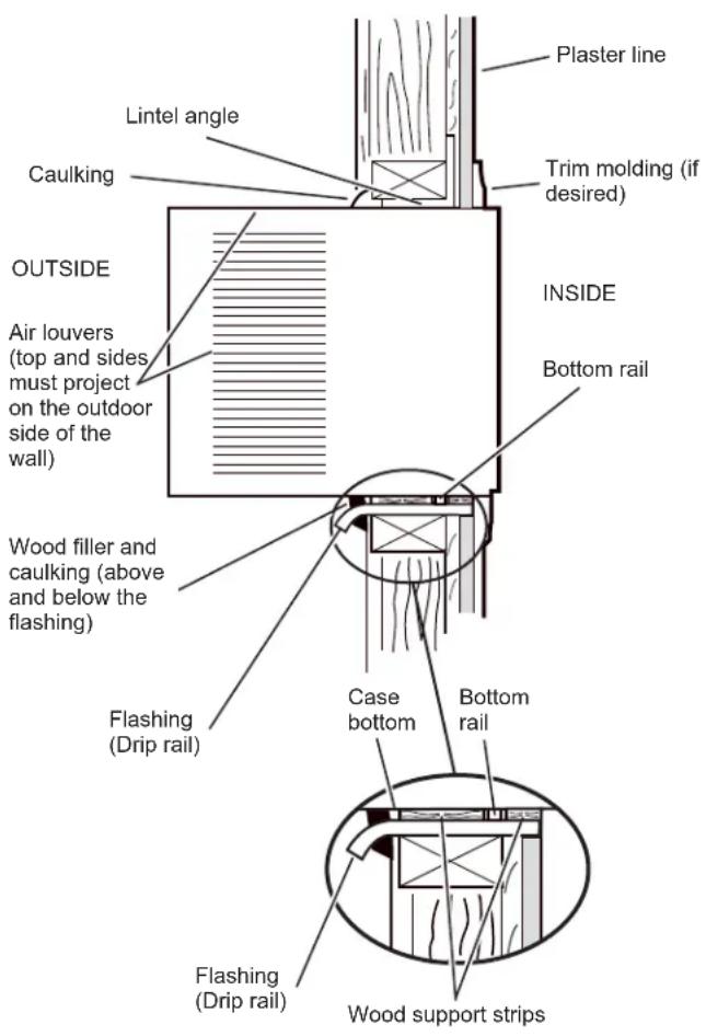
text_image
Plaster line Lintel angle Caulking Trim molding (if desired) OUTSIDE INSIDE Bottom rail Air louvers (top and sides must project on the outdoor side of the wall) Wood filler and caulking (above and below the flashing) Flashing (Drip rail) Case bottom Bottom rail Flashing (Drip rail) Wood support stripsB. Place the air conditioner into the case. For specific instruction, refer to the Window Installation Instructions.
Troubleshooting Tips... Before you call for service
Save time and money! Review the charts on the following pages first and you may not need to call for service.
| Problem Possible Causes What To Do | |
| Air conditioner The air conditioner • Make sure the air conditioner plug is pushed does not start is unplugged. completely into the outlet.The fuse is blown/circuit • Check the house fuse/circuit breaker box and replace breaker is tripped. the fuse or reset the breaker.Power failure. •The unit will automatically restart in the settings last used after the power is restored.•There is a protective time delay (approximately 3 minutes) to prevent tripping of the compressor overload. For this reason, the unit may not start normal cooling for 3 minutes after it is turned back on.The current interrupter •Press the RESET button located on the power cord plug. device is tripped. •If the RESET button will not stay engaged, discontinue use of the air conditioner and contact a qualified service technician. | |
| Air conditioner does not cool as it should | Airflow is restricted. •Make sure there are no curtains, blinds or furniture blocking the front of the air conditioner. |
| The temp control may | •In the Cool mode, press the Decrease pad. not be set correctly. |
| The air filter is dirty. See the Care and Cleaning section. | •Clean the filter at least every 30 days. |
| to allow time for the room | The room may have been hot. •When the air conditioner is first turned on, you need to cool down. |
| Cold air is escaping. | •Check for open furnace registers and cold air returns. |
| Cooling coils have iced up. | •See “Air conditioner freezing up” below. |
| Air conditioner freezing up | Ice blocks the air flow and stops the air conditioner from cooling the room. •Set the controls at High Fan or High Cool and set the thermostat to a higher temperature. |
| The remote control is not working | The batteries are inserted incorrectly. •Check the position of the batteries. They should be inserted in the opposite (+) and (−) direction. |
| The batteries may be dead. | •Replace the batteries. |
| Water drips outside | Hot, humid weather. •This is normal. |
| Water drips indoors tilted to the outside. | The air conditioner is not slants slightly from the case front to the rear. |
| Water collects in base pan | Moisture removed from air and drains into base pan. •This is normal for a short period in areas with little humidity; normal for a longer period in very humid areas. |
Normal Operating Sounds
■ You may hear a pinging noise caused by water being picked up and thrown against the condenser on rainy days or when the humidity is high. This design feature helps remove moisture and improve efficiency.
■ You may hear the thermostat click when the compressor cycles on and off.
■ Water will collect in the base pan during high humidity or on rainy days. The water may overflow and drip from the outdoor side of the unit.
■ The fan may run even when the compressor does not.
GE Appliances Air Conditioner - One-Year Limited Warranty
All warranty service provided by our Factory Service Centers, or an authorized Customer Care® technician. To schedule service, visit us on-line at ge.com, or call 800.GE.CARES (800.432.2737). Have serial number and model number available when calling for service.
| For The Period Of: | GE Appliances Will Replace: |
| One YearFrom the date of the original purchase | Any part of the air conditioner which fails due to a defect in materials or workmanship. During this limited one-year warranty, GE Appliances will also provide, free of charge, all labor and related service to replace the defective part. |
What GE Appliances Will Not Cover:
■ Service trips to your home to teach you how to use the product.
■ Improper installation, delivery or maintenance. If you have an installation problem, or if the air conditioner is of improper cooling capacity for the intended use, contact your dealer or installer. You are responsible for providing adequate electrical connecting facilities.
■ Failure of the product resulting from modifications to the product or due to unreasonable use including failure to provide reasonable and necessary maintenance.
■ In commercial locations, labor necessary to move the unit to a location where it is accessible for service by an individual technician.
■ Replacement of house fuses or resetting of circuit breakers.
■ Failure due to corrosion on models not corrosion-protected.
■ Damage to the product caused by improper power supply voltage, accident, fire, floods or acts of God.
■ Incidental or consequential damage caused by possible defects with this air conditioner.
■ Damage caused after delivery.
EXCLUSION OF IMPLIED WARRANTIES—Your sole and exclusive remedy is product repair as provided in this Limited Warranty. Any implied warranties, including the implied warranties of merchantability or fitness for a particular purpose, are limited to one year or the shortest period allowed by law.
This warranty is extended to the original purchaser and any succeeding owner for products purchased for home use within the USA. If the product is located in an area where service by a GE Appliances Authorized Servicer is not available, you may be responsible for a trip charge or you may be required to bring the product to an Authorized GE Appliances Service location for service. In Alaska, the warranty excludes the cost of shipping or service calls to your home.
Some states do not allow the exclusion or limitation of incidental or consequential damages. This warranty gives you specific legal rights, and you may also have other rights which vary from state to state. To know what your legal rights are, consult your local or state consumer affairs office or your state's Attorney General.
Warrantor: GE Appliances, a Haier company
Consumer Support
GE Appliances Website
Have a question or need assistance with your appliance? Try the GE Appliances Website 24 hours a day, any day of the year! You can also shop for more great GE Appliances products and take advantage of all our on-line support services designed for your convenience. In the US: GEAppliances.com
Register Your Appliance
Register your new appliance on-line at your convenience! Timely product registration will allow for enhanced communication and prompt service under the terms of your warranty, should the need arise. You may also mail in the pre-printed registration card included in the packing material. In the US: GEAppliances.com/register
Schedule Service
Expert GE Appliances repair service is only one step away from your door. Get on-line and schedule your service at your convenience any day of the year. In the US: GEAppliances.com/ge/service-and-support/service.htm or call 800.432.2737 during normal business hours.
Extended Warranties
Purchase a GE Appliances extended warranty and learn about special discounts that are available while your warranty is still in effect. You can purchase it on-line anytime. GE Appliances Services will still be there after your warranty expires. In the US: GEAppliances.com/ge/service-and-support/shop-for-extended-service-plans.htm or call 800.626.2224 during normal business hours.
Remote Connectivity
For assistance with wireless network connectivity (for models with remote enable), visit our website at GEAppliances.com/ge/connected-appliances/ or call 800.220.6899 in the US.
Parts and Accessories
Individuals qualified to service their own appliances can have parts or accessories sent directly to their homes (VISA, MasterCard and Discover cards are accepted). Order on-line today 24 hours every day. In the US: GEApplianceparts.com or by phone at 877.959.8688 during normal business hours.
Instructions contained in this manual cover procedures to be performed by any user. Other servicing generally should be referred to qualified service personnel. Caution must be exercised, since improper servicing may cause unsafe operation.
Contact Us
If you are not satisfied with the service you receive from GE Appliances, contact us on our Website with all the details including your phone number, or write to:
In the US: General Manager, Customer Relations | GE Appliances, Appliance Park | Louisville, KY 40225 GEAppliances.com/ge/service-and-support/contact.htm
INSTRUCCIONES
DE SEGURIDAD....3
USO DEL ACONDICIONADOR DE AIRE
Controle 4
CUIDADO Y LIMPIEZA
Filtro de aire 7
Bobinas para exteriores ..... 7
INSTRUCCIONES
natural_image
Line drawing of an electric air conditioner unit with a hand pointing to the grille (no text or symbols)Cuidado y Limpieza
Rejilla y caja
natural_image
Simple line drawing of a rectangular box with vertical bars on both sides, no text or symbols present.natural_image
Line drawing of a screwdriver with a magnified inset showing the tip (no text or symbols)natural_image
Illustration of hands installing or adjusting a solar panel cover on an air conditioner unit (no text or symbols visible)natural_image
Illustration of a portable air conditioner unit with ventilation grilles and ventilation grilles (no text or symbols)natural_image
Line drawing of an air conditioner unit with ventilation grilles and two upward arrows indicating airflow or heat (no text or symbols on the device itself)natural_image
Line drawing of a portable air conditioner unit with cooling fins and ventilation slots (no text or symbols)text_image
Top mounting rail4. PREPARE LA CARCASA
natural_image
Pure mechanical diagram showing two circular insets with zigzag components and a central block, no text or symbols present.natural_image
Two hand-drawn diagrams showing a panel with vertical grooves, one holding the other (no text or symbols)natural_image
Technical line drawing of a modular air duct or enclosure with vertical slats and internal compartments (no text or symbols)5. PREPARE LA VENTANA E INSTALE LA CAJA
natural_image
Hand holding a tool interacting with a surface, no text or symbols visiblenatural_image
Technical line drawing of a mechanical device with internal components and directional arrows (no text or symbols)natural_image
Line drawing of a mechanical or electrical enclosure with a grid-patterned base and top panel (no text or symbols)text_image
Diagram showing a hand pressing down a pipe with a magnified inset highlighting the pipe's tip and outlet.natural_image
Diagram of an air conditioning unit with cooling fans and ventilation grilles (no text or labels)natural_image
Illustration of a person opening a ventilation grille into a cabinet (no text or symbols visible)text_image
L1 L2 H Hnatural_image
Line drawing of a computer rack with ventilation grilles and a hand adjusting the front panel (no text or symbols)natural_image
Technical line drawing of a rectangular enclosure with bolt holes and mounting hardware (no text or symbols)En EE.UU.: General Manager, Customer Relations | GE Appliances, Appliance Park | Louisville, KY 40225 GEAppliances.com/ge/service-and-support/contact.htm