EBN368E - Security Camera EverFocus - Free user manual and instructions
Find the device manual for free EBN368E EverFocus in PDF.

User questions about EBN368E EverFocus
0 question about this device. Answer the ones you know or ask your own.
Ask a new question about this device
Download the instructions for your Security Camera in PDF format for free! Find your manual EBN368E - EverFocus and take your electronic device back in hand. On this page are published all the documents necessary for the use of your device. EBN368E by EverFocus.
USER MANUAL EBN368E EverFocus
Value IP Series Outdoor Network Camera
2-Megapixel 288 Series / 3-Megapixel 368 Series
User's Manual

natural_image
Exterior view of a white surveillance camera (no visible text or symbols)EBN288/368

text_image
EverFocusEDN288/368M

natural_image
Exterior view of a white surveillance camera with 'EverFocus' logo on the lens (no additional text or symbols visible)EZN288/368 EZN288/368M
natural_image
Exterior view of a white surveillance camera (no visible text or symbols)
EverFocus
Copyright © 1995-2017 EverFocus Electronics Corp.
Disclaimer
All the images including product pictures or screen shots in this document are for example only. The images may vary depending on the product and soware version. Informaon contained in this document is subject to change without noce.
Copyright
All rights reserved. No part of the contents of this manual may be reproduced or transmied in any form or by any means without written permission of the EverFocus Electronics Corporaon.
EverFocus
12F-1, No.79, Sec. 1, Shin-Tai Wu Road,
Hsi-Chih, New Taipei City, Taiwan
TEL: +886 2 2698 2334
FAX: +886 2 2698 3943
www.everfocus.com.tw
March, 2017
About this document
All the safety and operang instrucons should be read and followed before the unit is operated. This manual should be retained for future reference. The informaon in this manual was current when published. The manufacturer reserves the right to revise and improve its products. All specicaons are therefore subject to change without noce.
Regulatory Noces
FCC Noce "Declaraon of Conformity Informaon"
This equipment has been tested and found to comply with the limits for a Class
A digital device, pursuant to part 15 of the FCC Rules. These limits are designed to provide reasonable protecon against harmful interference in a residential installaon. This equipment generates, uses and can radiate radio frequency energy and, if not installed and used in accordance with the instrucons, may cause harmful interference to radio communicaons. However, there is no guarantee that interference will not occur in a parcular installaon. If this equipment does cause harmful interference to radio or television recepon, which can be determined by turning the equipment o and on, the user is encouraged to try to correct the interference by one or more of the following measures:
- Reorient or relocate the receiving antenna.
- Increase the separaon between the equipment and receiver.
- Connect the equipment into an outlet on a circuit dierent from that to which the receiver is connected.
- Consult the dealer or an experienced radio/TV technician for help.
Warning: Changes or modicaons made to this equipment, not expressly approved by EverFocus or pares authorized by EverFocus could void the user's authority to operate the equipment.
This device complies with part 15 of the FCC Rules. Operaon is subject to the following two conditions:
(1) This device may not cause harmful interference, and
(2) This device must accept any interference received, including interference that may cause undesired operaon.
EverFocus Electronics Corp.
12F-1, No. 79, Sec. 1, Shin-Tai Wu Rd.,
Hsi-Chi, New Taipei City, Taiwan
Value IP Series camera complies with CE and FCC.
Precauons
Do not install the camera near electric or magnec elds.
Install the camera away from TV/radio transmiers, magnets, electric motors, transformers and audio speakers since the electromagnec elds generated from these devices may distort the video image or otherwise interfere with camera operaon.
Never disassemble the camera beyond the recommendations in this manual nor introduce materials other than those recommended herein.
Improper disassembly or introducon of corrosive materials may result in equipment failure or other damage.
Try to avoid facing the camera toward the sun.
In some circumstances, direct sunlight may cause permanent damage to the sensor and/or internal circuits, as well as creang unbalanced illuminaon beyond the capability of the camera to compensate.
- Keep the power cord away from water and other liquids and never touch the power cord with wet hands.
Touching a wet power cord with your hands or touching the power cord with wet hands may result in electric shock.
- Never install the camera in areas exposed to oil, gas or solvents.
Oil, gas or solvents may result in equipment failure, electric shock or, in extreme cases, re.
- Cleaning
For cameras with interchangeable lenses, do not touch the surface of the sensor directly with the hands. Use lens ssue or a coon pped applicator and ethanol to clean the sensor and the camera lens. Use a damp so cloth to remove any dirt from the camera body. Please do not use complex solvents, corrosive or abrasive agents for cleaning of any part of the camera.
- Do not operate the camera beyond the specied temperature, humidity or power source ranges.
Use the camera at temperatures within -10^ 50^ / 14^ 122^ , and humidity between 0% and 90%; this device is not rated as submersible. The input power source is 12VDC / PoE. Be sure to connect the proper + / - polarity and voltage, as incorrect polarity or too high a voltage will likely cause the camera to fail, and such damage is not covered by the warranty. The use of properly fused or Class 3 power limited type supplies is highly recommended.
- Mounng
Use care in selecng a solid moung surface which will support the weight of the camera plus any wind, snow, ice or other loading, and securely each the camera to the moung surface using screws and anchors which will properly support the camera. If necessary (e.g. when moung to drop ceilings) use a safety wire to provide additional support for the camera.
CONTENTS
- Introduction....1
- Physical Description 2
2.1. Dimensions 4
- Features .... 5
- Installation....6
4.1. Packing List....6
4.2. Optional Accessory 7
4.3. Cables 8
4.4. Basic Installation....10
4.4.1. Mounting and Wiring....10
4.4.2. Inserting a Micro SD Card 19
- Accessing the Camera....22
5.1. Checking the Dynamic IP Address 22
S.2. Settings for Microsoft Internet Explorer....24
5.3. Connecting the Camera to the Network....25
5.4. Live View Window 27
- Quick Setup Panel 29
6.1 Streaming....29
6.2 Camera....30
7.1.5.1. Upgrade Firmware 40
7.1.5.2. Auto Reboot 41
7.1.5.3. Restore 42
7.1.6. System Information 43
7.1.7. User 44
7.1.8. Serial Communication....46
7.1.9. Local Settings 47
7.2. Camera Settings 48
7.2.1. Streaming and Audio 48
7.2.1.1. Audio Settings....48
7.2.1.2. Stream Settings....49
7.2.1.3. Privacy Mask Settings 50
7.2.2. Camera....51
7.2.3. Image 54
7.3. Event Settings 55
7.3.1. Event 55
7.3.1.1. Motion Settings 55
7.3.1.2. Tamper Detection Settings 57
7.3.1.3. Alarm Input 58
7.3.1.4. Alarm Output....60
7.3.1.5. Exception Settings 61
7.3.2. Notification 62
7.3.2.1. Email Settings 62
7.4. Search and Play 63
7.4.1
1. Introducon
The Value IP 2-megapixel 288 / 3-megapixel 368 series H.265 Outdoor IP camera provides 30fps at 1920 x 1080 / 2048 x 1536 viewing resoluon. The series supports dual streams from H.265 or H.264 video compression formats. In same resoluon, the H.265 provides higher compression eciency and lower bitrate comparing with H.264 codec, allowing more ecient bandwidth and data storage usage. The True Wide Dynamic Range (WDR) funcon on the other hand enables the IP camera to provide clear images even under back light circumstances where intensity of illuminaon can vary excessively.
Featured with a motorized zoom lens, EDN288M / EZN288M / EDN368M / EZN368M can provide the desired eld of view with superior video quality in precise focus. Equipped with a weather-proof (IP66) housing, the Value IP 288 / 368 series meets a wide variety of needs for outdoor surveillance. Except 12VDC power supply, the series also supports Power over Ethernet (IEEE 802.3af), which eliminates the need for power cables and thus reduce the installaon costs.
The Value IP 288 / 368 series conforms to ONVIF for compatibility with other network video devices. You can also use EverFocus Mobile applicaons to remotely view the live views of the cameras through your iOS or android handheld devices; or use EverFocus CMS to remotely manage mulple IP devices connected on the network.
| Model Name | Lens | Max. Video Resoluon | Storage | IR / T-WDR | IP66 / IK10 |
| EBN288 | 3.6mm | 1920 x 1080 | - | Yes / Yes | Yes / - |
| EBN368 | Fixed lens | 2048 x 1536 | |||
| EDN288M | 2.8-12mm | 1920 x 1080 | Micro SD / SDHC / SDXC slot (Max. 128G, up to class 10) | Yes / Yes | |
| EDN368M | Motorized lens | 2048 x 1536 | |||
| EZN288 | 3.6mm | 1920 x 1080 | Yes / - | ||
| EZN368 | Fixed lens | 2048 x 1536 | |||
| EZN288M | 2.8-12mm | 1920 x 1080 | |||
| EZN368M | Motorized lens | 2048 x 1536 |
System Requirement
Before installing, please check that your computer meets the following system requirements.
• Operang System: Microso Windows XP / Vista (32-bit) / 7 (32-bit)
- Microso Internet Explorer 11 or later, Chrome (Windows version 44 and earlier), Firefox version 50 and earlier, EverFocus Browser
Note: For using the Internet Explorer, some settings are required. Please refer to 5.2 Senqs for Microso Internet Explorer.
2. Physical Descripon
EBN288/368

text_image
3 2 1 EAGL0CT2| No. | Item Name | Descripons |
| 1 | IR LEDs | IR LEDs for infrared illuminaon in night vision applicaons. |
| 2 | Lens | Fixed lens. |
| 3 | Light Sensor | Detects lights. |
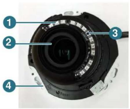
EDN288/368M
text_image
Labeled diagram of a camera lens system with numbered components| No. | Item Name | Descripons |
| 1 | IR LEDs | IR LEDs for infrared illuminaon in night vision applicaons. |
| 2 | Lens | Motorized lens. |
| 3 | Light Sensor | Detects lights. |
| 4 | Micro SD / SDHC Slot | Insert a micro SD / SDHC card (see Appendix for tested card brands). |
EZN288/368
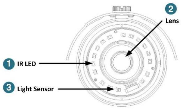
text_image
1 IR LED 2 Lens 3 Light Sensor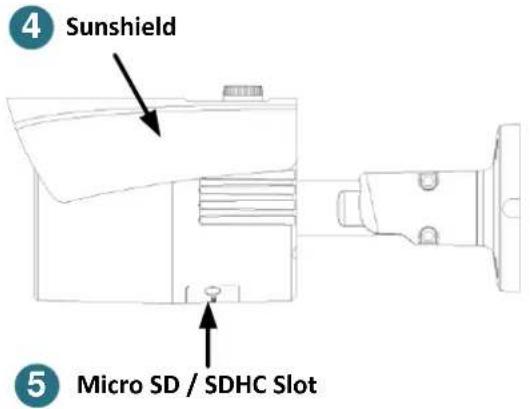
text_image
4 Sunshield 5 Micro SD / SDHC Slot| No. | Item Name | Descripons |
| 1 | IR LEDs | IR LEDs for infrared illuminaon in night vision applicaons. |
| 2 | Lens | Fixed lens. |
| 3 | Light Sensor | Detects lights. |
| 4 | Sunshield | Protect the camera from the direct rays of the sun. |
| 5 | Micro SD / SDHC Slot | Insert a micro SD / SDHC card (see Appendix for tested card brands). |
EZN288/368M

text_image
1 IR LED 2 Lens 1 IR LED 3 Light Sensor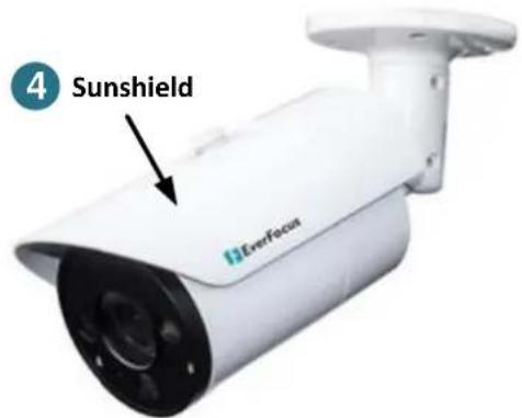
text_image
4 Sunshield EverFocus| No. | Item Name | Descripons |
| 1 | IR LEDs | IR LEDs for infrared illuminaon in night vision applicaons. |
| 2 | Lens | Motorized lens. |
| 3 | Light Sensor | Detects lights. |
| 4 | Sunshield | Protect the camera from the direct rays of the sun. |
2.1. Dimensions
EBN288/368
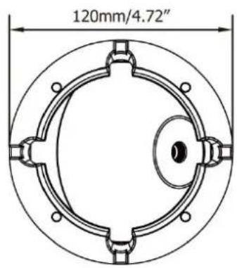
text_image
120mm/4.72"
text_image
95mm/3.74"EDN288/368M
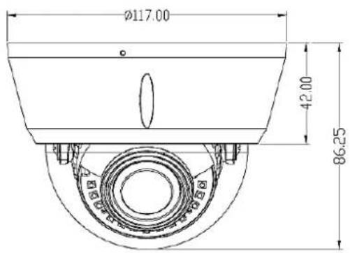
text_image
Ø117.00 42.00 86.25EZN288/368

text_image
87.47 80.50 Ø71.00
text_image
185.71 105.00EZN288/368M

text_image
263 Ø93
natural_image
Technical drawing of a mechanical component with circular features and dimension标注 (no text or symbols)3. Features
• SONY Progressive Scan CMOS sensor
• Astounding image quality from the 3.6mm lens (EBN288 / EBN 368 / EZN288 / EZN368)
- Motorized 2.8-12mm lens to capture the desired eld of view (EDN288M / EDN368M / EZN288M / EZN368M)
• True Wide Dynamic Range Funcon (120dB)
- Provides True Day/Night funconality with automac IR Iter operaon
• Extended IR range up to 30m / 100. with IR LEDs (Depending on scene IR reecvity)
- Mul-streaming from H.265 / H.264
• 1080p full real me recording
- Weather proof IP66-rated
• The exible angle viewing with its 3-Axis rotaon design allows wall or ceiling mounng
• Supports Moon Detecon & Email Nocaon
- Supports live monitoring of video from mobile devices via MobileFocus / MobileFocus plus Apps (iOS & Android)
• Supports Power over Ethernet / 12VDC
- Low light
- Two-way audio*
• Supports Alarm I/O*
• Supports RS-485 (reserved)*
• EverFocus Genie XMS CMS
• ONVIF prole S compliant
• Supports Micro SD card (EDN288M / EDN368M / EZN288 / EZN368 / EZN288M / EZN368M)
4. Installaon
4.1. Packing List
Please check that there is no missing item in the package before installing.
| No. | Item Name | EBN288/368 | EDN288/368M | EZN288/368 | EZN288/368M |
| 1 | Camera | x 1 | x 1 | x 1 | x 1 |
| 2 | MAC Address Scker | x 2 | x 2 | x 2 | x 2 |
| 3 | Screw Anchor (in conjuncon with Screw) | x 4 | x 3 | x 3 | x 4 |
| 4 | Screw | x 4 | x 3 | x 3 | x 4 |
| 5 | Hexagon Wrench (for adjusng the camera posion) | x 1 | - | x 1 | x 1 |
| 6 | Cable Gland Kit (connect to the LAN/PoE cable for waterproong) | x 1 | x 1 | x 1 | x 1 |
| 7 | Set Screw | x 3 | - | - | - |
| 8 | Power Pigtail Cable | x 1 | x 1 | x 1 | x 1 |
| 9 | Accessories Instrucon (for installaon of Set Screw) | x 1 | - | - | - |
| 10 | Soware CD | x 1 | x 1 | x 1 | x 1 |
| 11 | Quick Installaon Guide | x 1 | x 1 | x 1 | x 1 |
| 12 | Scker (Mounng Template) | x 1 | x 1 | x 1 | x 1 |
Note:
- Equipment conguraons and supplied accessories vary by country. Please consult your local EverFocus oce or agents for more informaon. Please also keep the shipping carton for possible future use.
- Contact the shipper if any items appear to have been damaged in the shipping process.
4.2. Oponal Accessory
You can use the oponal accessories to expand the capabilities and versatility of the camera. Please contact your dealer for more informaon.
| Juncon Box | |
PBOX-A32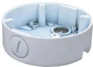 | Juncon Box (For EBN288/368)Apple White119.2 x 38mm / 4.7" x 1.5" (D) x (H)High-strength Aluminum for beer protecon against damage.Spray painted surface to protect the bracket from corrosion and rust. |
PBOX-A32-1 | Juncon Box (For EZN288 / EZN368 / EZN288M / EZN368M)Apple White119.2 x 38mm / 4.7" x 1.5" (D) x (H)High-strength Aluminum for beer protecon against damage.Spray painted surface to protect the bracket from corrosion and rust. |
PBOX-A32-2 | Juncon Box (For EDN288M / EDN368M)Apple White119.2 x 38mm / 4.7" x 1.5" (D) x (H)High-strength Aluminum for beer protecon against damage.Spray painted surface to protect the bracket from corrosion and rust. |
| IP Sidekick | |
IP Sidekick - ESK1000 | Using it for installaon, you do not need to pre-congure the IP address or to use an additional monitor to check and adjust all the IP cameras. The product can assign an IP address to the camera, then you can connect and check the camera live view using EverFocus mobile App EF Sidekick. For details about IP Sidekick, please refer to the IPSidekick – ESK1000 User's Manual. |
| PoE Switch | |
EverFocus 5 / 8 / 16 / 24Ports PoE Switch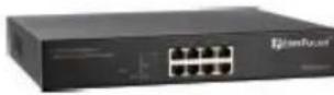 | 5 Ports: ES0501-408 Ports: ES0812-31 / ES0802-4116 Ports: ES1625-31 / ES1645-5124 Ports: ES2426-31 / ES2446-51 / ES2448-62 |
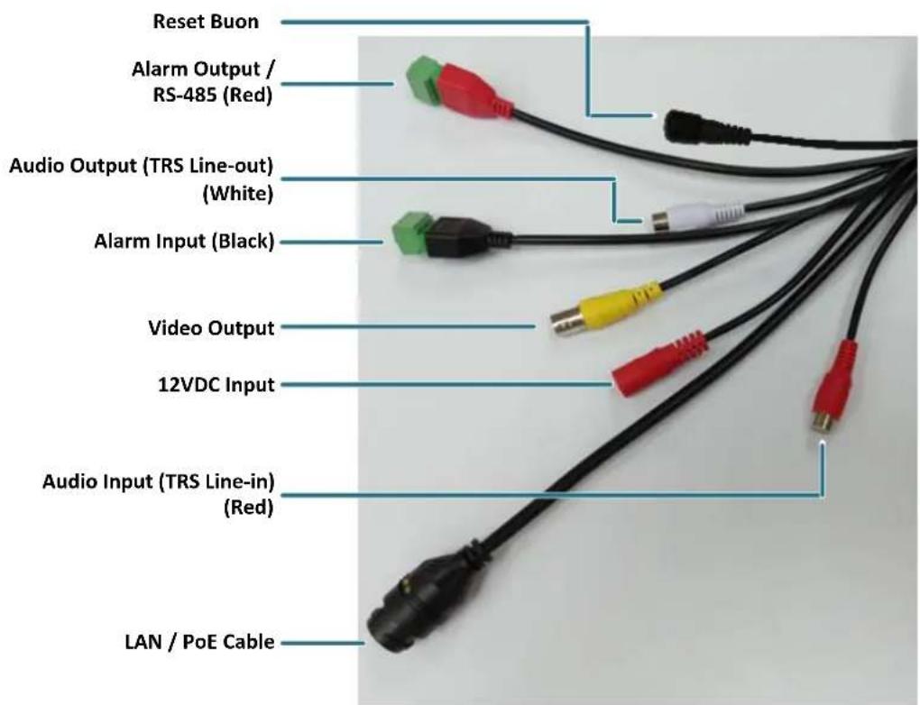
4.3. Cables
The Cables provide connecons for Network, BNC output, power, audio input / output, RS-485 (reserved) and alarm inputs / output. A Reset Buon is also provided. Note that the audio-in / out cable features a line 3.5mm jack (TRS). Be sure to prepare microphones / speakers with TRS connector (see TRS Connector image below). Also, microphones / speakers with a (built-in) amplifier and external power supply are required.
text_image
Reset Buon Alarm Output / RS-485 (Red) Audio Output (TRS Line-out) (White) Alarm Input (Black) Video Output 12VDC Input Audio Input (TRS Line-in) (Red) LAN / PoE Cable| Cable | EBN288/368 | EDN288/368M | EZN288/368 | EZN288/368M |
| Alarm In x 2 | Yes (with a terminal block) | Yes (with a terminal block) | Yes (with a terminal block) | Yes (with a terminal block) |
| Alarm Out / RS-485 (reserved) | Yes (with a terminal block) | Yes (with a terminal block) | Yes (with a terminal block) | Yes (with a terminal block) |
| Audio In | Yes (Red) | Yes (Red) | Yes (Red) | Yes (Red) |
| Audio Out | Yes (White) | Yes (White) | Yes (White) | Yes (White) |
| BNC | Yes | Yes | Yes | Yes |
| RJ45 | Yes | Yes | Yes | Yes |
| 12VDC | Yes | Yes | Yes | Yes |
| Reset Buon | Yes (with a dust-proof cap) | - | - | Yes (with a dust-proof cap) |
For Economic models, the cables provide connecons for Network, power and Reset Buon.

text_image
Reset Buon 12VDC Input LAN / PoE CableEconomic Models Cables
| Cable | EBN288/368 | EDN288/368M |
| RJ45 | Yes | Yes |
| 12VDC | Yes | Yes |
| Reset Buon | Yes (with a dust-proof cap) | - |
| Cable | EZN288/368 | EZN288/368M |
| RJ45 | Yes | Yes |
| 12VDC | Yes | Yes |
| Reset Buon | - | Yes (with a dust-proof cap) |
Audio Funcon

text_image
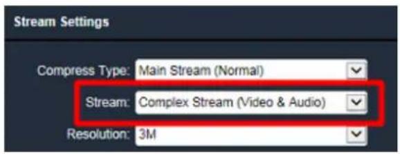
TRS Connector Ground (Sleeve) Right Channel (Ring) Le Channel (Tip)To acvate the Audio funcon, the Complex Stream must be selected. See Stream in 7.2.1.2 Streaming Sengs.
text_image
Stream Settings Compress Type: Main Stream (Normal) Stream: Complex Stream (Video & Audio) Resolution: 3MPin Assignment
| Alarm Output / RS-485 (reserved) | ||
| Alarm Output | COM (-) | |
| NO (+) | ||
| RS-485(reserved) | B (+) | |
| A (-) | ||
| Alarm Input | ||
| Alarm In 1 | GND (-) | |
| Alarm In (+) | ||
| Alarm In 2 | Alarm In (+) | |
| GND (-) | ||
Reset Buon
- Reboot the camera:
When the camera is powered up, press the Reset Buon will reboot the camera.
- Restore the camera:
Keep the Reset Buon pressed, at the same me unplug the camera power then plug it back again will return camera sengs to the factory default values.
4.4. Basic Installaon
4.4.1. Mounng and Wiring
EBN288/368
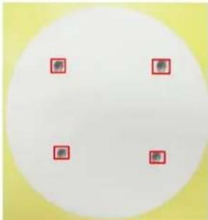
- Before screwing the camera to the wall, sick the Scker on the wall / ceiling to mark the position for installaon. Drill four holes on the wall / ceiling according to the supplied Scker and push the supplied four Screw Anchors into the four holes on the wall / ceiling. Drill another hole in the middle of the Scker if you wish to run the wires into the wall / ceiling.
natural_image
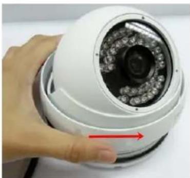
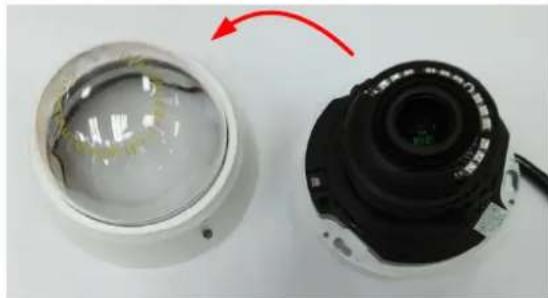
Circular white shape with four red square markers on a yellow background (no text or symbols)- Twist the Outer Housing counterclockwise and then remove the Outer Housing from the camera base.
natural_image
Close-up of a hand holding a white surveillance camera with a red arrow pointing to the lens (no text or symbols visible)- Place the camera base on the wall / ceiling and run the cable through the camera base rst.
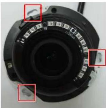
4. Tread the cables:
a. From the side cut of the camera base

natural_image
Close-up of a circular mechanical component with red square highlights, no visible text or symbolsb. Through the wall / ceiling: run the cables through the hole on the wall / ceiling.
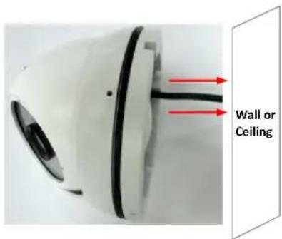
text_image
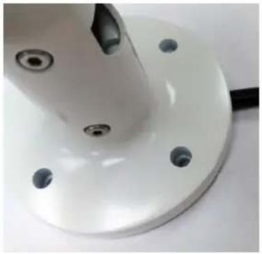
Wall or Ceiling- Use the supplied four Screws to screw the camera base to the ceiling / wall.

natural_image
Circular mechanical component with internal black and white lines, no visible text or symbols-
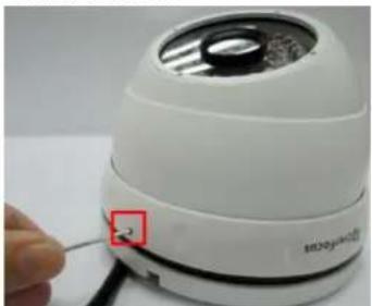
Adjust the camera angle and twist back the Outer Housing simultaneously.
-
Oponally screw back the Set Screw by using the supplied Hexagon Wrench to prevent uninstallaon.
natural_image
Close-up of a white electronic device with a small circular button labeled '2' and a red square marker, being held by a hand (no readable text or symbols beyond the label)- Connect the LAN / PoE cable to the camera.
a. Remove the Screw Cap from the Cable Gland.

text_image
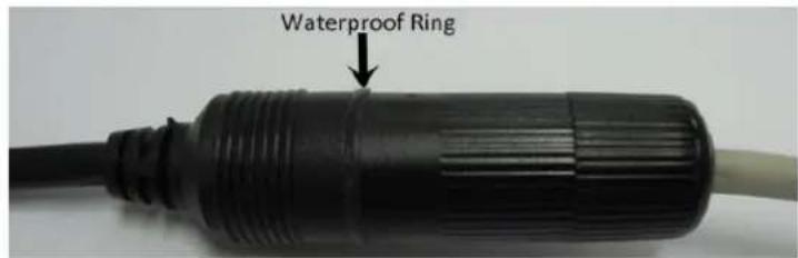
Screw Cap Cable Glandb. Insert a RJ-45 network cable (without the RJ-45 connector on the one end) through the Cable Gland and Screw Cap.

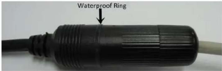
text_image
Waterproof Ring Cable Gland Stopper Screw Capc. Place the Waterproof Ring into the LAN / PoE cable. Connect the RJ-45 cable to the RJ-45 Connector Cable. Tightly screw the Cable Gland and Screw Cap to the RJ-45 Connector Cable.
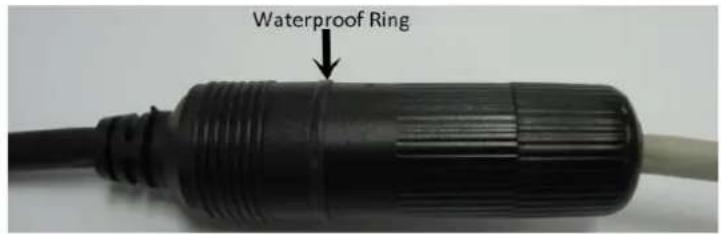
text_image
Waterproof Ring- Oponally connect the camera to the 12VDC power source using the supplied Power Adapter Pigtail or a power adapter.

text_image
Power Cable RJ-45 Connector Power Adapter or Power Adapter PigtailEDN288/368M
- Before screwing the camera to the wall, sick the Scker on the wall / ceiling to mark the position for installaon. According to the supplied Scker, drill three screw-depth holes on the wall / ceiling, and then drill a through-wall hole for wiring the camera cables. Push the supplied three Screw Anchors into the four holes on the wall / ceiling.

text_image
Wall or Ceiling Scker Anchors Screws- Unscrew the camera cover and screw the camera base to the ceiling / wall by using the supplied Screws.
natural_image
Close-up of a camera lens with three red-circled adjustment knobs and a central aperture (no text or symbols visible)-
Oponally insert the micro SDHC / SDXC card. Please refer to 4.4.2 Inserng a micro SD Card.
-
Connect the LAN / PoE cable to the camera.
a. Remove the Screw Cap from the Cable Gland.

text_image
Screw Cap Cable Glandb. Insert a RJ-45 network cable (without the RJ-45 connector on the one end) through the Cable Gland and Screw Cap.

text_image
Waterproof Ring Cable Gland Stopper Screw Capc. Place the Waterproof Ring into the LAN / PoE cable. Connect the RJ-45 cable to the RJ-45 Connector Cable. Tightly screw the Cable Gland and Screw Cap to the RJ-45 Connector Cable.
text_image
Waterproof Ring- Oponally connect the camera to the 12VDC power source using the supplied Power Adapter Pigtail or a power adapter.

text_image
Power Cable RJ-45 Connector Power Adapter or Power Adapter Pigtail-
Access the camera live view. See 5. Accessing the Camera. Or using a video Test-Out cable to connect a monitor to the camera for seng image aim and focus.
-
To adjust camera angles.
Pan Adjustment: Simply turn le / right of the 3-Axis bracket by 75° to the desired posion.

text_image
75° 75° 3-Axis BracketRotaonal Adjustment: Loosen the rotate screw and rotate the camera le / right to the desired posion, then ghten the rotate screw. Due to the internal connector design, it is recommended not to rotate the camera more than 30°.

text_image
30° 30° Rotaon screwTilt Adjustment: Loosen the two lt screws and adjust the angle by 75^ to the desired posion, then ghten the lt screw.

text_image
Tilt screw 75°- Secure the cover back to the camera.
EZN288/368 & EZN288/368M
- Before screwing the camera to the wall, sick the Scker on the wall / ceiling to mark the posion for installaon. Drill three (EZN288/368) or four (EZN288/368M) holes on the wall / ceiling according to the supplied Scker and push the supplied Anchors into the three holes on the wall / ceiling. Drill another hole in the middle of the Scker if you wish to run the wires into the wall / ceiling.

natural_image
Technical line drawing of a mechanical assembly with no visible text or symbolsEZN288/368

natural_image
Technical line drawing of a mechanical assembly with cylindrical components and mounting flanges (no text or symbols)EZN288/368M
- You can wire the cables from the side of the camera or through the wall.
natural_image
Close-up of a white mechanical component with mounting holes and a curved base (no text or symbols visible)Wire the cables from the side of the camera
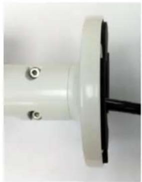
natural_image
Close-up of a white cylindrical mechanical component with a black rod inserted, no visible text or symbols.Wire the cables through the wall
-
Place the camera's base against the anchoring surface so that the holes line up. Screw the camera to the wall / ceiling using the supplied Screws.
-
Oponally insert a micro SD / SDHC card into the card slot. Please refer to 4.4.2 Inserng a micro SD Card.
-
Connect the LAN / PoE cable to the camera.
a. Remove the Screw Cap from the Cable Gland.

text_image
Screw Cap Cable Glandb. Insert a RJ-45 network cable (without the RJ-45 connector on the one end) through the Cable Gland and Screw Cap.

text_image
Waterproof Ring Cable Gland Stopper Screw Capc. Place the Waterproof Ring into the LAN / PoE cable. Connect the RJ-45 cable to the RJ-45 Connector Cable. Tightly screw the Cable Gland and Screw Cap to the RJ-45 Connector Cable.
text_image
Waterproof Ring- Oponally connect the camera to the 12VDC power source using the supplied Power Adapter Pigtail or a power adapter.

text_image
Power Cable RJ-45 Connector Power Adapter or Power Adapter Pigtail- Access the camera live view. See 5. Accessing the Camera. Or connect a handheld test monitor to the CVBS wire on the Cable Assembly for adjusng viewing angles.
- To adjust the camera angles:
Pan Adjustment: Loosen the Set Screw using the supplied Hexagon Wrench. Rotate the camera by 360° to the desired posion and screw the Set Screw unl it locks against the Camera Base.
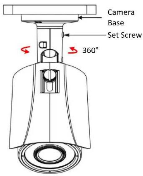
text_image
Camera Base Set Screw 360°EZN288/368
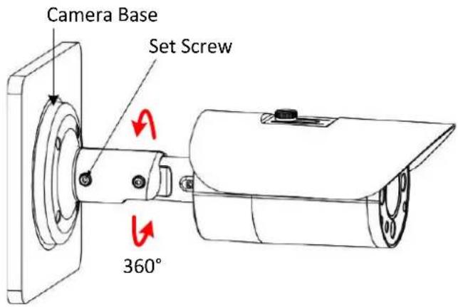
text_image
Camera Base Set Screw 360°EZN288/368M
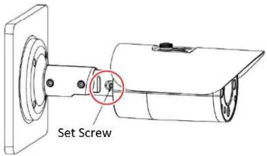
Tilt Adjustment: Loosen the Set Screw using the provided Hexagon Wrench and adjust the angle by 90°.

Rotaonal Adjustment: Loosen the Screw using the provided Hexagon Wrench and rotate the camera by 360°.
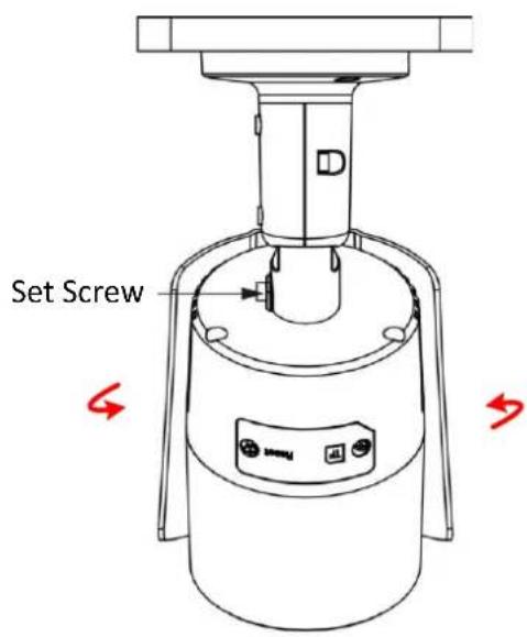
text_image
Set ScrewEZN288/368

text_image
Set ScrewEZN288/368M
Note:
- Before start operang the IP camera, please make sure the camera date and me are correct. To congure the camera date/me, go to System > Date/Time seng page on Web UI.
- By default, the system will automatically adjust the IR LED strength according to the scene, so please avoid IR reecon when installing the camera to prevent out-of-focus at night.
- Under Auto focus mode, if the camera does not focus aer switching the Day/Night mode, it is recommended to switch the focus mode to Manual and adjust focus manually.
4.4.2. Inserng a Micro SD Card
You can oponally insert a micro SD card to the card slot on the camera module for recording videos. Before inserng a micro SD card, make sure you turn o the camera rst.
EDN288/368M
- Unscrew and then remove the camera cover.
natural_image
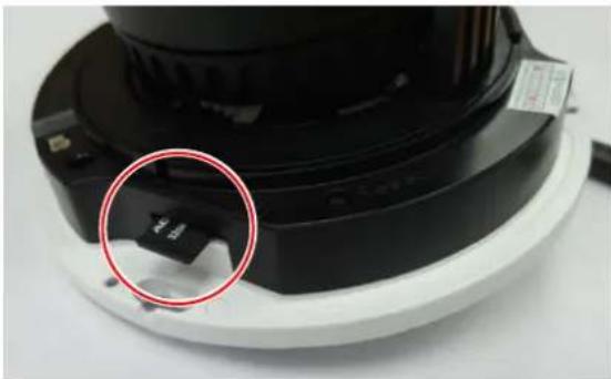
Close-up of a camera lens and its internal components, showing light reflections and a red arrow indicating rotation (no text or symbols)- Insert a micro SD card into the card slot.
natural_image
Close-up of a black camera module with a red circle highlighting a small component, no visible text or symbols.EZN288/368
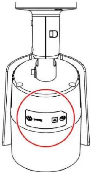
- Open the cover on the boom of the camera by loosening the screws.
text_image
Technical diagram of a device with labeled components and a red circle highlighting a component with three buttons.- Insert a micro SD card into the card slot.
EZN288/368M
- Loosen the two set screws on the bracket.
text_image
Set Screw- Loosen the three screws on the rear housing. Rotate and then remove the rear housing.
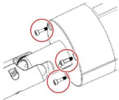
natural_image
Technical line drawing of a mechanical component with three red-circled features (no text or symbols)- Loosen the four screws on the IPC board.
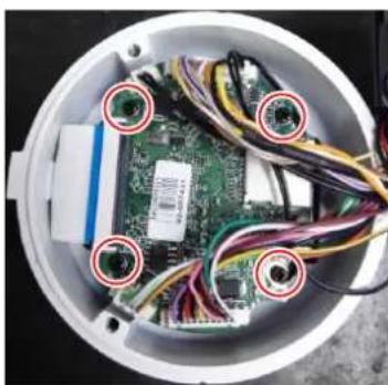
natural_image
Interior view of an open electronic device showing exposed circuit board and wiring (no text or symbols visible)- Insert a micro SD card into the card slot.
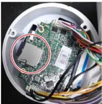
natural_image
Interior view of an electronic device showing a green circuit board with exposed components and wiring (no visible text or symbols)- Put the water-proof ring on the groove that near the edge of the housing. Place the desiccant bag beside the IPC board.
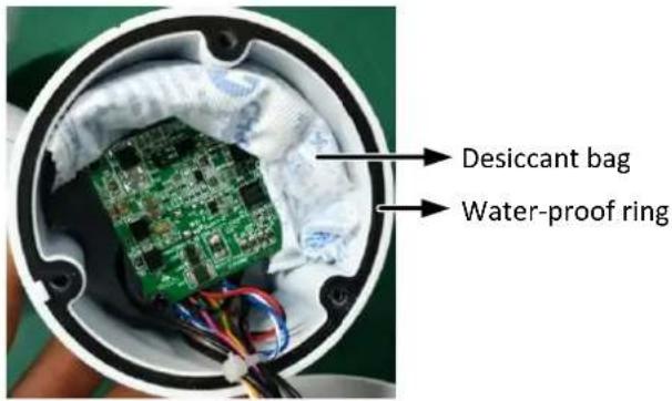
text_image
Desiccant bag Water-proof ring- Screw back the IPC board, secure the rear housing back to the front housing and ghten the set screws on the bracket.
Note: Please make sure you wear the anstac gloves or anstac wrist strap when installing the Micro SD card to protect the device from damage.
5. Accessing the Camera
This secon explains how to access the Web interface of the camera for conguraon.
5.1. Checking the Dynamic IP Address
You can look up the IP address and access the Web interface of the IP camera using the IP Utility (IPU) program, which is included in the soware CD. The IP Utility can also be downloaded from EverFocus' Website: hp://www.everfocus.com.tw/HQ/Support/DownloadCenter_p1.aspx (Support > Download Center > Keyword Search: IP Utility). Please connect the IP camera on the same LAN of your computer.
1. Save IP Ulity Setup .exe

in your computer. Double click the .exe le and follow the on-screen instrucons to install the IP Utility.
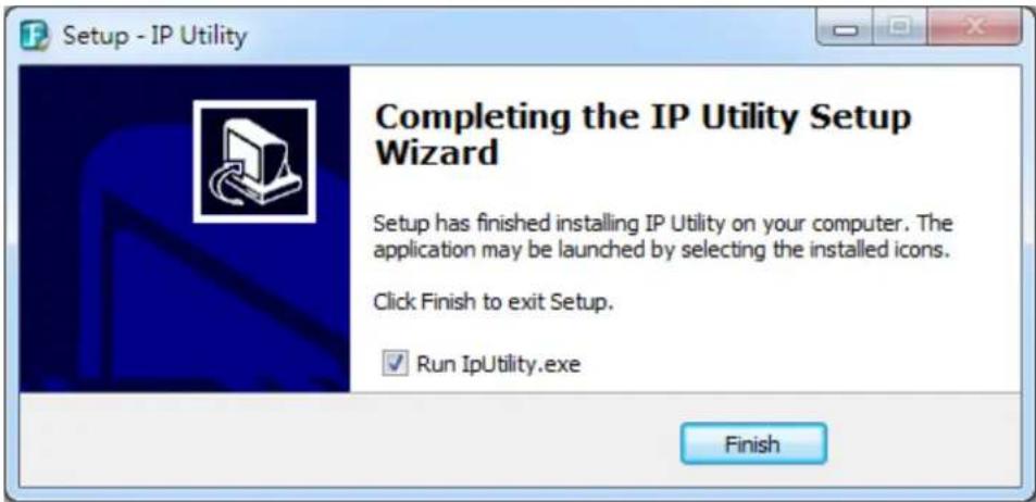
text_image
Setup - IP Utility Completing the IP Utility Setup Wizard Setup has finished installing IP Utility on your computer. The application may be launched by selecting the installed icons. Click Finish to exit Setup. ✓ Run IpUtility.exe Finish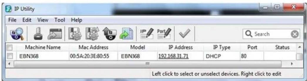
text_image
IP Utility File Edit View Tool Help Machine Name Mac Address Model IP Address IP Type Port Status EBN368 00:5A:20:3E:80:55 EBN368 192.168.31.71 DHCP 80 Left click to select or unselect devices. Right click to edit- To access the Live View window, double click the IP address of the desired device, the login window pops up. Type the user ID and password to log in. By default, the user ID is user1 and the password is 11111111.
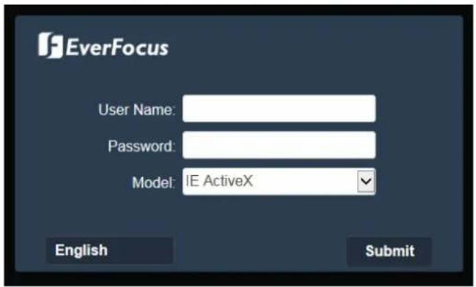
text_image
EverFocus User Name: Password: Model: IE ActiveX English Submit- Click Submit, the Live View window appears.
Note:
- To enable Remote Live View, Firmware Upgrade and AcveX Prompt on Internet Explorer, some sengs have to be complete. Please refer to 5.2 Sengs for Microso Internet Explorer.
-
The default IP mode of the IP camera is DHCP. However, if there is no dynamic IP address assigned to the device, its IP will switch to 192.168.0.10.
-
To oponally congregate the Machine Name, IP Address, IP Type or Port Number using the IPU:
a. Log in the camera by checking the desired model and then click the Log in icon. The Log in dialog box appears.

text_image
IP Utility File Edit View Tool Help Log in Username user1 Password OK Cancel EBN368 N/A Search Port Status 80b. Type the Username and Password. Click the OK buon, the Login status displays.
| Machine Name | Model | IP Address | IP Type | Port | Status |
| EBN368 | EBN368 | 192.168.32.135 | DHCP | 80 | Login |
Note:
- The default user ID is user1 and the default password is 11111111.
- If you select more than one camera that has the same user ID / password, you will be able to log in several cameras at once.
c. Right click the column to congregate the sengs. Click the Apply Changes buon to apply and save the sengs.
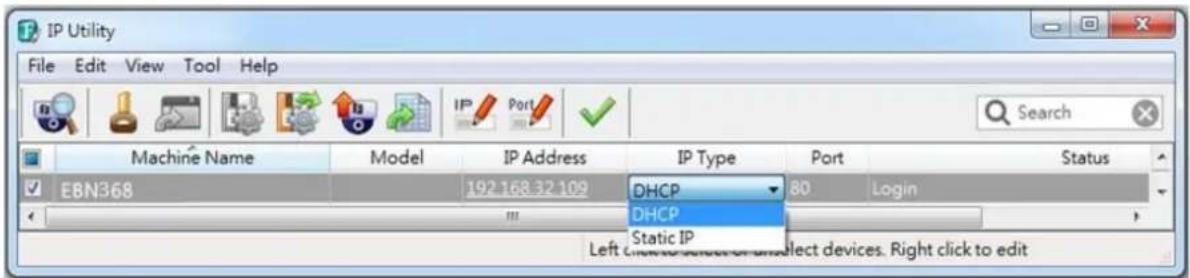
text_image
IP Utility File Edit View Tool Help Machine Name Model IP Address IP Type Port Status EBN368 192.168.32.109 DHCP 80 Login Static IP Left Connection Devices or Select devices. Right click to edit5.2. Sengs for Microso Internet Explorer
If you have dicules viewing live view or upgrading rmware, it is suggested to complete the following sengs of your computer.
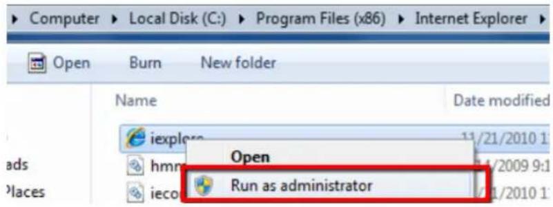
- If your PC or laptop is running with Windows, it's required to run the browser as administrator when rst entering the remote web page of the device. Go to C:\Program Files (x86)\Internet Explorer, right-click the browser and then click Run as administrator.
text_image
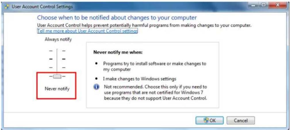
Computer > Local Disk (C:) > Program Files (x86) > Internet Explorer Open Burn New folder Name Date modified iexplera 11/21/2010 1 hmm Open 5/1/2009 9:1 ieco Run as administrator 5/1/2010 1- You may need to turn User Account Control off if you sll can't see the Remote Live View. On the computer, click Start > Control Panel > System and Security > Acon Center (click Change User Account Control Sengs), the User Account Control Sengs window appears. Adjust the slide bar to Never Nofy and then click OK. Restart your computer if requested.
text_image
User Account Control Settings Choose when to be notified about changes to your computer User Account Control helps prevent potentially harmful programs from making changes to your computer. Tell me more about User Account Control settings? Always notify Never notify Never notify me when: • Programs try to install software or make changes to my computer • I make changes to Windows settings i Not recommended. Choose this only if you need to use programs that are not certified for Windows 7 because they do not support User Account Control.5.3. Connecng the Camera to the Network
There are three methods to connect the IP camera to the network: Router or LAN Connecon, Direct High-Speed Connecon and One-to-One Connecon.
Router or LAN conncon
This is the most common conncon in which the IP camera is connected to a router and allows mulple users on and o site to see the IP camera on a LAN / WAN (Internet). The camera must be assigned an IP address that is compatible with its LAN. By seng up port forwarding on the router, you can remotely access the cameras from outside of the LAN via the Internet. To remotely access the Web interface of the IP camera, please refer to 7.1.1 Network (DDNS Setngs). To set up port forwarding, please refer to Appendix D. Seng up Port Forwarding Funcon.
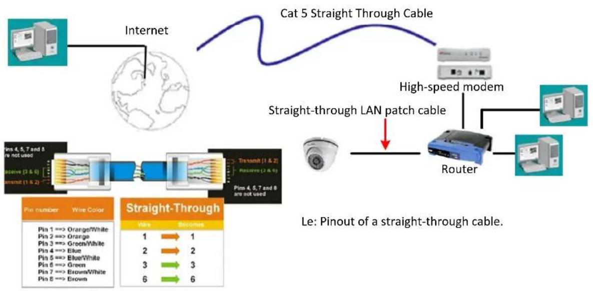
flowchart
graph TD
    A["Internet"] --> B["Cat 5 Straight Through Cable"]
    B --> C["High-speed modem"]
    C --> D["Router"]
    D --> E["Satellite"]
    F["Pin number Wire Color"] --> G["Straight-Through"]
    H["Pin 1 => Orange/White"] --> I["Blue"]
    J["Pin 2 => Orange"] --> K["Green/White"]
    L["Pin 3 => Green/White"] --> M["Blue/White"]
    N["Pin 4 => Blue"] --> O["Blue/White"]
    P["Pin 5 => Blue/White"] --> Q["Green/White"]
    R["Pin 6 => Green"] --> S["Brown/White"]
    T["Pin 7 => Brown/White"] --> U["Brown"]
    V["Pin 8 => Brown"] --> W["Brown"]
    X["Le: Pinout of a straight-through cable."] --> Y["Straight-through LAN patch cable"]
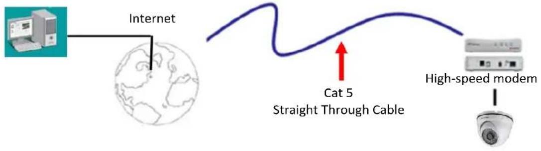
Direct High-Speed Connecon
In a Direct High-Speed Connecon, the camera connects directly to a modem without the need for a router. You need to set the stac or dynamic WAN IP address assigned by your ISP (Internet Service Provider) in the camera's conguraon web pages. To access the camera, just type "hp://xxx.xxx.xxx.xxx", where xxx.xxx.xxx.xxx is the IP address given by your ISP. If you have a dynamic IP address, this conncon may require that you use DDNS for a reliable conncon. Please refer to Appendix E. Seng up DDNS Funcon.
flowchart
graph LR
    A["Internet"] --> B["Global Map"]
    B --> C["Cat 5 Straight Through Cable"]
    C --> D["High-speed modem"]
    style A fill:#f9f,stroke:#333
    style B fill:#ccf,stroke:#333
    style C fill:#cfc,stroke:#333
    style D fill:#fcc,stroke:#333
One-to-One Connecon (Directly from PC to IP Camera)
You can connect directly without using a switch, router or modem. However, only the PC connected to the camera will be able to view the IP camera. You will also have to manually assign a compatible IP address to both the computer and the IP camera. Unless the PC has another network conncon, the IP camera will be the only network device visible to the PC. See the diagram below:
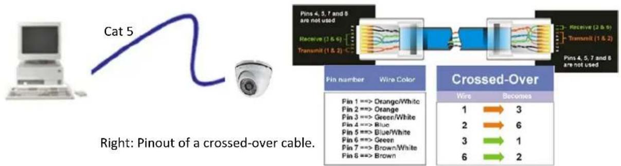
flowchart
graph LR
    A["Cat 5"] --> B["Right: Pinout of a crossed-over cable."]
    B --> C["Pin number Wire Color"]
    C --> D["Crossed-Over"]
    D --> E["1 → 3"]
    D --> F["2 → 6"]
    D --> G["3 → 1"]
    D --> H["6 → 2"]
5.4. Live View Window
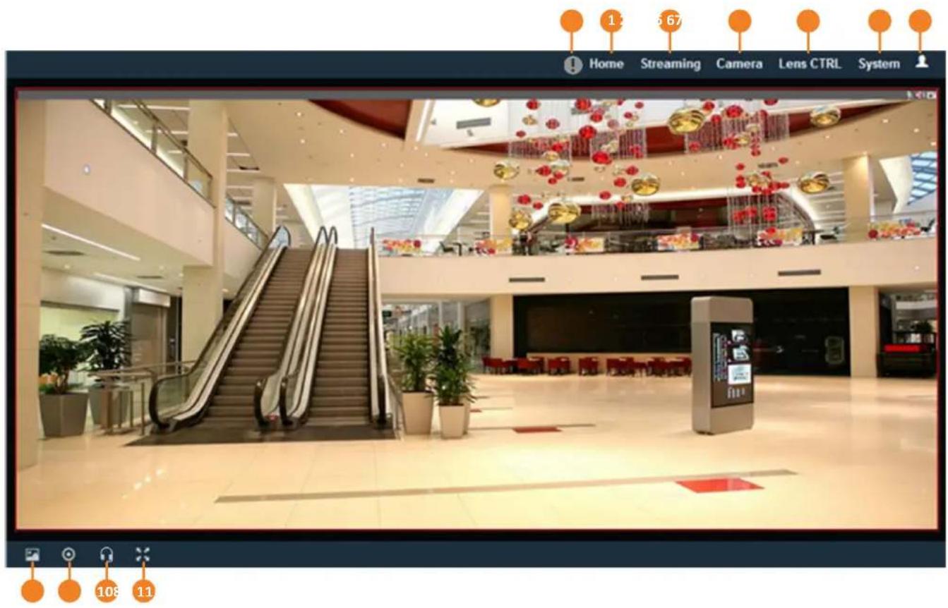
text_image
Home Streaming Camera Lens CTRL System 1 67 108 111. Home
Click the tab to display the Live View window. On the Live View Window, you can directly operate the zoom in / out by scrolling your mouse wheel over the image.
2. Streaming
Click the Streaming tab to display the Streaming quick setup panel. See 6.1 Streaming for more details.
3. Camera
Click the tab to display the Camera quick setup panel. See 6.2 Camera for more details.
4. Lens CTRL
Click the tab to display the Lens Control quick setup panel. See 6.3 Lens CTRL for more details. The funcon is only available for EDN288/368M and EZN288/368M.
5. System
Click the tab to enter the Sengs page. See 7. System for more details.
6. Account
Click the buon to display the Account panel. You can check the current log-in informaon, or log out of the Web interface by clicking Lougout. See 6.4 Account for more details.
7. Event signal icons
When an event is triggered, the alarm icon ⚠️ at the top of the Live View window will turn red and blink ⚠️ to alert the user. Click the icon to view the alarm informaon. On the pop-up window, click Disarming / Arming to stop / start prompting alarm informaon, click Clear Alarm to remove the current alarm informaon from the list.
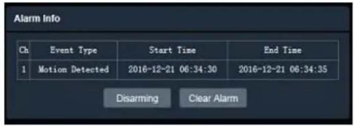
text_image
Alarm Info Ch Event Type Start Time End Time 1 Motion Detected 2016-12-21 06:34:30 2016-12-21 06:34:35 Disarming Clear Alarm8. Snapshot
Click the Snapshot buon to take a snapshot, and the storage folder will pop up automacally. By default, the snapshot will be saved at C:Everfocus/Value_3M/Snapshots. To change the locaon, see Live View Snapshot in 7.1.9 Local_Sengs.
9. Record
Click the Record buon to start / stop recording the current video stream. By default, the recordings will be saved at C:Everfocus/Value_3M/Recordings. To change the locaon, see Live View Recording in 7.1.9 Local Sengs.
10. Two-way Audio
Click the Two-way Audio buttons to switch the sound on / o for the speakers and microphones (if such external devices have been connected to the camera directly or via the network). To activate the Audio funcon, the Complex Stream must be selected. See Stream in 7.2.1.2 Stream Setngs. Note that the camera provides the TRS line-in / out terminal I/O, therefore, TRS microphones / speakers with a (built-in) amplifier and external power supply are required.
11. Full Screen
Click to display the current camera stream in full screen. To exit full screen, right-click the mouse or press the ESC buon on keyboard. Under full screen mode, these icons help you quickly be alerted of moon events, turn the audio on/o and take snapshots.
When a moon event is triggered, the alarm icon will turn red to alert the user.
Click the Audio buons to switch the sound on / o for the speakers (if such external devices have been connected to the camera directly or via the network).
Click the Snapshot buon to take a snapshot.

EverFocus
Value IP 2MP 288 Series / 3MP 368 Series
6. Quick Setup Panel
You can click the ▶ button to display the panel over the live view. Click the ◀ button to fix the panel on
the right-side. Click the X button or the Close Control Panel button to close the panel.
6.1 Streaming
Click the Streaming tab to display the streaming quick setup panel.
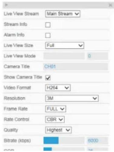
text_image
Live View Stream Stream Info Alarm Info Live View Size Full Live View Mode 0 Camera Title CH01 Show Camera Title Video Format H264 Resolution 3M Frame Rate FULL Rate Control CBR Quality Highest Bitrate (kbps) 6000Live View Stream: Select from Main Stream and Sub Stream.
Stream Info: Check to show the current bitrate and current frame rate at the top of the Live View window.
Alarm Info: Check to show the current triggered alarm type and trigger time.
Live View Size: Select the appropriate view size of the live view window.
Live View Mode: Slide the bar to set up the live stream performance between Real Time (smaller value) and Smooth way (larger value).
Camera Title: Type a name in the column to change the title.
Show Camera Title: Check to show the camera title. Format: Select the encoding format - H.265 or H.26
Resolution: Select the most suitable resolution for your needs.
Emma Data: Select from 16 to Full Emma. The
6.2 Camera
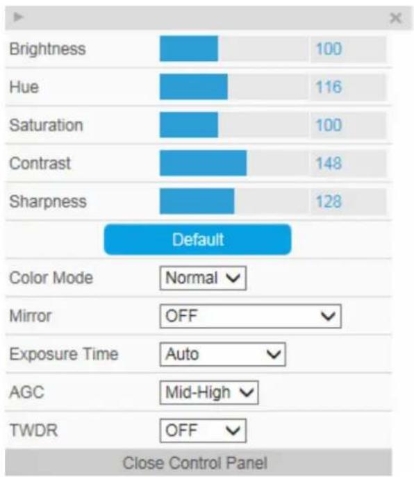
Click the Camera tab to display the camera quick setup panel.
bar
| Feature | Value | |---|---| | Brightness | 100 | | Hue | 116 | | Saturation | 100 | | Contrast | 148 | | Sharpness | 128 | Default Color Mode Normal ✓ Mirror OFF ✓ Exposure Time Auto ✓ AGC Mid-High ✓ TWDR OFF ✓ Close Control PanelBrightness: Slide the bar to adjust brightness.
Hue: Slide the bar to adjust hue.
Saturaon: Slide the bar to adjust saturaon.
Contrast: Slide the bar to adjust contrast.
Sharpness: Slide the bar to adjust sharpness.
Default: Click to return the above value to factory default.
Color Mode: Select a color mode from Normal, Bright or Nature. The default color mode is Normal.
Mirror: Select a mirror mode from OFF, Horizontal Mirror, Vercal Mirror or 90 / 180 / 270 degree Rotaon (see 7.2.3 Image for more details). The default Mirror mode is OFF.
Exposure Time: Select an exposure mode from auto or a shuer speed (from 1/25 \~ 1/10,000 seconds).
AGC: For Auto Exposure mode, you can further congregate the AGC value. Select the Auto Gain Control level from Low to High (see 7.2.2 Camera for more details). The default AGC level is Mid-High.
TWDR: There are four value opons: Close, Low, Mid and High (see 7.2.2 Camera for more details). The default TWDR mode is OFF.
6.3 Lens CTRL
Click the Lens CTRL tab to display the lens control quick setup panel.

text_image
Focus Mode Auto Speed 5 Zoom In Zoom Out Focus Near Focus Far Close Control PanelFocus Mode: Select a focus mode from Auto, or Manual. For Manual, use the Focus Near / Focus Far buons to adjust focus.
Speed: Use the slider to adjust the speed for Zoom and Focus.
Zoom In / Zoom Out: Use the buons to adjust Zoom in or out.
Focus Near / Focus Far: Use the buons to adjust Focus near or far.
Note:
- By default, the system will automatically adjust the IR LED strength according to the scene, so please avoid IR reecon when installing the camera to prevent out-of-focus at night.
- Under Auto focus mode, if the camera does not focus aer switching the Day/Night mode, it is recommended to switch the focus mode to Manual and adjust focus manually.
6.4 Account
Click the

on to display the account panel.

text_image
user1 Logout Close ControlsAccount: Display the current user's login account. Logout: Click to log out of the Web interface.
7. System
Click the System tab on the Live View Window to enter the setng page. Click the item of the one you want to see in the seng menu to display the details.

text_image
EverFocus Home System System Settings Network Date / Time Storage Display and Overlay System Maintenance System Information User Serial Communication Local Settings Camera Settings Streaming and Audio Camera Image Event Settings Event Notification Search and Play File Log System Information Device Name: EBN368 Model Name: EBN368 Device Type: IPC Firmware Version: 1.0.1_161209 Format: 50Hz Save7.1. System Sengs
7.1.1. Network
You can congregate network-related sengs, including IP, Mulcast, DHCP, DDNS and Port on this page. Click the tab of the one you want to see.
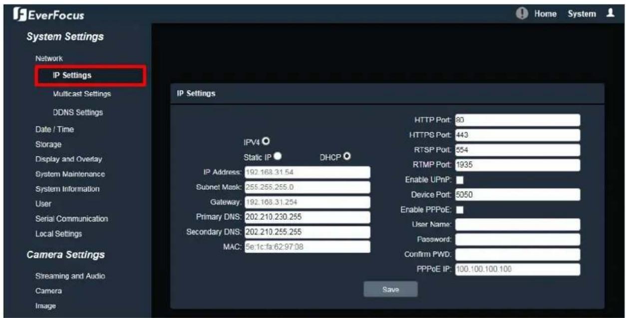
7.1.1.1. IP Sengs
Enter the IPv4 details in this area, which applies to your system.
text_image
EverFocus System Settings Network IP Settings Multicast Settings DDNS Settings Date / Time Storage Display and Overlay System Maintenance System Information User Serial Communication Local Settings Camera Settings Streaming and Audio Camera Image IP Settings IPV4 Static IP DHCP HTTP Port: 80 HTTPS Port: 443 RTSP Port: 554 RTMP Port: 1935 Enable UPnP: Device Port: 5050 Enable PPPoE: User Name: Password: Confirm PWD: PPPoE IP: 100.100.100.100 SaveIPV4: Click the radio to enable IPv4 (Internet Protocol version 4), and then enter the IPv4 details in this area.
Stac IP: Click the radio to enable Stac IP. You can manually set the Stac IP address. This type of address is stable and cannot change, but the user has to make sure there are no address conicts with other network-connected devices.
DHCP: Click the radio to enable DHCP. This seng lets the system use an automacally assigned (dynamic) IP address. This address can change under certain circumstances. For instance, when the camera's network switch / hub has to be rebooted. Do not assign to the DHCP server the same IP addresses used for the other network cameras and PCs with unique IP addresses.
IP Address: When DHCP is not used, the user needs to manually enter the IP address of the camera. Do not enter an IP address that is already used for your computer or other network cameras.
Subnet Mask: This eld is used to set the subnet mask for your network, so that the IP camera will be recognized within the network. Example: 255.255.255.0. When DHCP is selected, the DHCP server will assign this value automacally.
Gateway: This eld is used to set the gateway for your network so that the IP camera will be recognized within the network. When DHCP is selected, the DHCP server will assign this value automacally.
Primary DNS: Enter the IP address of the DNS server if this is provided by an ISP.
Secondary DNS: If your ISP provided you with a secondary DNS address, please enter it here.
MAC: The value of MAC address cannot be changed on this page, and are for reference only.
HTTP Port: Enter HTTP port numbers. The default port number is 80.
HTTPS Port: Enter HTTPS port numbers. The default port number is 443.
RTSP Port: Use domain name to access and login device need mapping RTSP. The default port number is 554.
RTMP Port: Use domain name to access and login device need mapping RTMP. The default port number is 1935.
Enable UPnP: Click the box to enable UPnP. Promoted by the UPnP Forum (Universal Plug and Play), the UPnP is a networking architecture providing compatibility among networked devices listed in the networked device table. Enable the UPnP funcon means you can directly connect the cameras listed in the networked device table by clicking on them.
Device Port: Enter device port numbers. The default port number is 5050.
Enable PPPoE: Click the box to enable PPPoE. This is a DSL-connecan applicaon. The ISP will ask the user to input a username and password. Contact your ISP for these details.
User Name: Enter the account's username for PPPoE.
Password: Enter the account's password for PPPoE.
Conrm PWD: Enter the password again to conrm it.
PPPoE IP: Enter the device's dynamic IP address.
Aer complete the sengs, click Save to apply the changes.
7.1.1.2. Mulcast Sengs
Enable if required, ll in the seng opons for main stream / sub stream video and audio. For more details, please refer to Appendix B. Enabling the Mulcast Funcon.
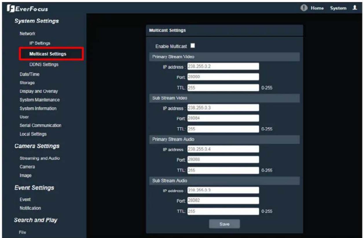
text_image
EverFocus System Settings Network IP Settings Multicast Settings DDNS Settings Date/Time Storage Display and Overlay System Maintenance System Information User Serial Communication Local Settings Camera Settings Streaming and Audio Camera Image Event Settings Event Notification Search and Play File Multicast Settings Enable Multicast Primary Stream Video IP address : 238.255.0.2 Port : 26080 TTL : 255 0-255 Sub Stream Video IP address : 238.255.0.3 Port : 26084 TTL : 255 0-255 Primary Stream Audio IP address : 238.255.0.4 Port : 26088 TTL : 255 0-255 Sub Stream Audio IP address: 219.255.0.3 Port : 26082 TTL : 255 0-255 SaveEnable Mulcast: Check the box to enable the Mulcast funcon.
IP Address: Fill in the mulcast IP address. IP addresses in the range of 224.0.0.0 through 239.255.255.255 are reserved for mulcasng. For devices, you can use 225.x.x.x - 232.x.x.x and 234.x.x.x - 238.x.x.x. Click here for more details.
Port: Change the port number if necessary.
TTL: Input a Time-To-Live (TTL) value. The TTL value species the number of routers (hops) that mulcast trac is permied to pass through before expiring on the network.
Aer complete the sengs, click Save to apply the changes.
7.1.1.3. DDNS Sengs
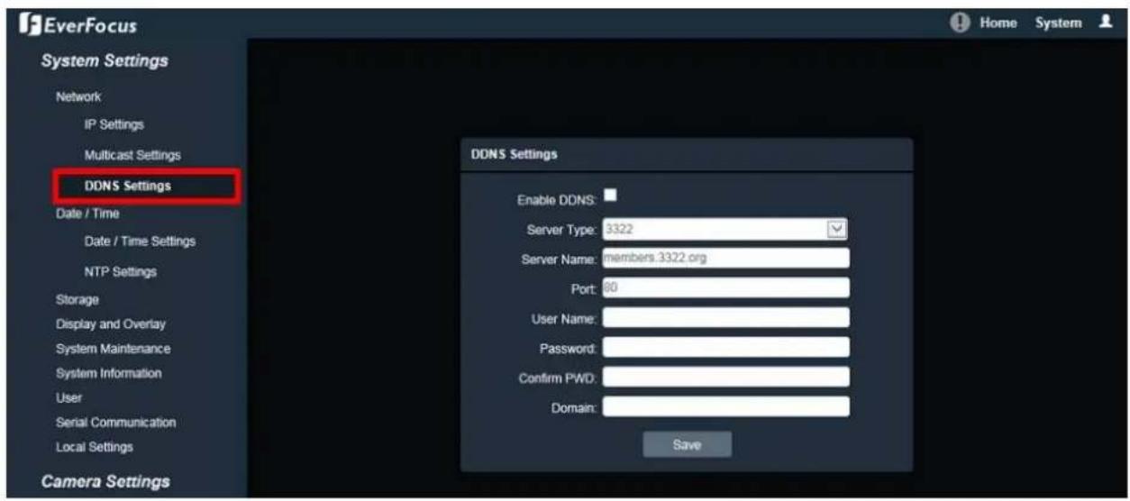
text_image
EverFocus System Settings Network IP Settings Multicast Settings DDNS Settings Date / Time Date / Time Settings NTP Settings Storage Display and Overlay System Maintenance System Information User Serial Communication Local Settings Camera Settings DDNS Settings Enable DDNS: Server Type: 3322 Server Name: members 3322 org Port: 60 User Name: Password: Confirm PWD: Domain: SaveDDNS (Dynamic Domain Name System) is a service used to map a domain name to the dynamic IP address of a network device. You can set up the DDNS service for remote access to the IP camera. DDNS assigns a domain name (URL) to the IP camera, so that the user does not need to go through the trouble of checking if the IP address assigned by DHCP Server has changed. Once the IP is changed, the IP camera will automatically update the informaon to the DDNS to ensure it is always available for remote access. For seng up the DDNS funcon, please refer to Appendix E. Seng up DDNS Funcon.
Before enabling the following DDNS funcon, user should have applied for a host name from the DDS service provider's website. We support these DDNS server providers:
www.everfocusddns.com, members.dyndns.org, ddns.oray.org, dynupdate.no-ip.com, members.3322.org and www.dnsdynamic.org
Note: We highly recommend that you use xxxx.everfocusddns.com for the simplicity of seng up your IP cameras.
Enable DDNS: Check the box to enable DDNS funcon.
Service: You can either apply for a host name from EverFocus or other DDNS server providers (Dyndns, PeanutHull, NO-IP, 3322 and DnsDynamic). If you choose the EverFocus DDNS server, you can obtain a free host name from EverFocus.
From EverFocus: To obtain a free host name from EverFocus, type a desired host name in the Domain eld (there is no need to enter username / password).
From other DDNS server providers: To obtain a domain name from one of the three DDNS server providers, you have to register your name with the provider rst, and then select the provider
and II in the required informaon. Please refer to the speci DDNS company's website for further informaon.
Server Name: The server name of the DDNS provider. For example, www.everfocusddns.com. You can modify the server name if required.
Port: Enter the port numbers. The default port number is 80.
User Name / Password: Type the login account of your DDNS server provider. Type the password again in the Conrm PWD eld.
Domain: Type the registered domain name from the DDNS server provider.
Aer complete the sengs, click Save to apply the changes.
Note:
- In order to support the full functionality of the camera, you must open the port numbers (80, 554, 443) on the router for remote access to the IP camera. This funcon is available on most routers in the market and is oen known as “Port Forwarding”. To set up Port Forwarding, please consult the manual of the router.
- In certain router models, it is possible that you will not be able to access the camera using DDNS while inside the router's network. Please try using a PC located outside of your router's network.
Default Ports on All EverFocus IP Cameras:
HTTP: 80
RTSP: 554
HTTPS: 443
7.1.2. Date / Time
You can set up the system's me and NTP server. Click the tab of the one you want to see.
Note: Before start operang the IP camera, please make sure the camera date and me are correct.
7.1.2.1. Date/Time Sengs
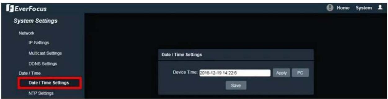
text_image
EverFocus System Settings Network IP Settings Multicast Settings DDNS Settings Date / Time Date / Time Settings NTP Settings Date / Time Settings Device Time: 2016-12-19 14:22:6 Apply PC SaveDevice Time: Display the device current me. You can manually set up and click Apply to save the me seng. Click PC to automatically adjust the camera's me by synchronizing with the PC.
Aer complete the sengs, click Save to apply the changes.
7.1.2.2. NTP Sengs

text_image
EverFocus System Settings Network IP Settings Multicast Settings DONS Settings Date / Time Date / Time Settings NTP Settings Storage Display and Overlay System Maintenance System Information User Serial Communication NTP Settings Enable NTP Server Address: http0.nl.net NTP Port: 123 Interval for Time Sync: 2 min Select Time Zone: GMT+0:00 London, Morocco GMT: 0 hour 0 min Adjust SaveEnable: Check the box to enable NTP funcon.
NTP Server Address: Enter the Network Time Protocol server, if applicable. The camera's me will be automatically adjusted by synchronizing with the NTP server.
NTP Port: Enter the Network Time Protocol port. The default port number is 123.
Interval for Time Sync: Input the interval me for automac me synchronizaon with NTP.
Select Time Zone: Select the me zone of the camera's locaon.
GMT: Check the Adjust box to enable adjusting the onset and set the desired minute in the min eld.
Aer complete the sengs, click Save to apply the changes.
7.1.3. Storage
You can check the SD Card utility or format the SD Card using this page.
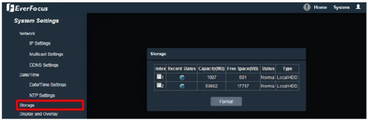
text_image
EverFocus System Settings Network IP Settings Multicast Settings DDNS Settings Date/Time Date/Time Settings NTP Settings Storage Display and Overlay Storage Index Record Status Capacity(MB) Free Space(MB) Status Type 1 1007 601 Norma LccalHDD 2 59882 17767 Norma LccalHDD FormatIf a micro SD card has been inserted to the micro SD card slot of the camera, the micro SD card informaon will be displayed in this eld, such as capacity, available free space and record status.
To format the card, click the Format button and all data saved on the micro SD card will be removed (see 4.4.2 Inserng a Micro SD Card).
Note:
- The Storage funcon is only available for EDN288/368M, EZN288/368 and EZN288/368M.
- Before you insert or remove the SD card, please turn o the IP camera rst.
7.1.4. Display and Overlay
You can enable displaying camera information on the live view / backup images using this page.
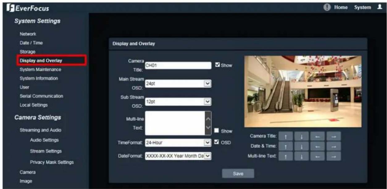
text_image
EverFocus System Settings Network Date / Time Storage Display and Overlay System Maintenance System Information User Serial Communication Local Settings Camera Settings Streaming and Audio Audio Settings Stream Settings Privacy Mask Settings Camera Image Display and Overlay Camera: CH01 ✓ Show Title: Main Stream OSD: Sub Stream OSD: Multi-line Text: TimeFormat: 24-Hour ✓ OSD DateFormat: XXXX-XX-XX Year Month Da ✓ Save Camera Title: ↑ ↓ ← → Date & Time: ↑ ↓ ← → Multi-line Text: ↑ ↓ ← →Camera Title: Check the Show box to enable the Camera Title function. Type a name in the column to change the title.
Main Stream OSD: Select the font size for main stream OSD.
Sub Stream OSD: Select the font size for sub stream OSD.
Mul-line Text: Enter the desired text in the input field, and check the Show box to display the text.
Time Format: Check the OSD box to enable the Time Format function. Select the desired time format from the drop-down list.
Date Format: Check the OSD box to enable the Date Format function. Select the desired date format from the drop-down list.
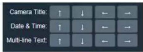
text_image
Camera Title: ↑ ↓ ← → Date & Time: ↑ ↓ ← → Multi-line Text: ↑ ↓ ← →Camera Title: You can adjust the position of the title by the arrow buttons.
Date & Time: You can adjust the position of the date / time by the arrow buttons.
Mul-line Text: You can adjust the position of the Multi OSD by the arrow buttons.
7.1.5. System Maintenance
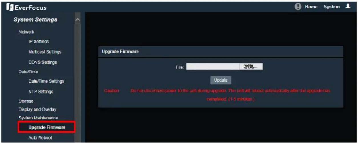
7.1.5.1. Upgrade Firmware
text_image
EverFocus System Settings Network IP Settings Multicast Settings DDNS Settings Date/Time Date/Time Settings NTP Settings Storage Display and Overlay System Maintenance Upgrade Firmware Auto Reboot Upgrade Firmware File: 浏览... Update G caution Do not disconnect power to the unit during upgrade. The unit will reboot automatically after the upgrade has completed (1-5 minutes.) Home SystemClick the Browse button to nd a previously prepared rmware upgrade le. Click the Update buon to install the new rmware. You can also upgrade rmware using IP Ulity, see 8. Upgrading Firmware Using IP Ulity.
Note:
- System updang should only be accomplished by trained sta.
- Do not disconnect power to the IP camera during the upgrade sequence. The IP camera will reboot automacally aer the upgrade has completed (1-5 minutes).
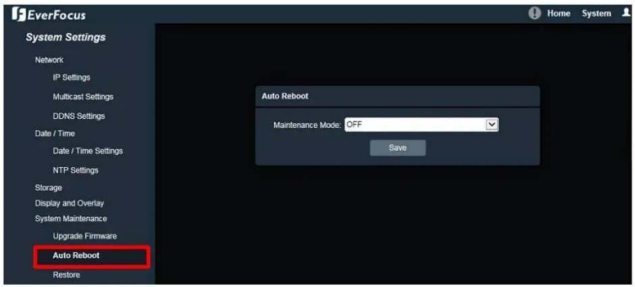
7.1.5.2. Auto Reboot
text_image
EverFocus System Settings Network IP Settings Multicast Settings DDNS Settings Date / Time Date / Time Settings NTP Settings Storage Display and Overlay System Maintenance Upgrade Firmware Auto Reboot Restore Auto Reboot Maintenance Mode: OFF SaveSelect OFF to disable the Auto Reboot funcon, or select an interval for the Auto Reboot funcon from Every Day, Every Week or One Time. The IP camera will automacally reboot at the specied me.
• OFF: The IP camera will not reboot automacally.
• Every Day: The IP camera will reboot automacally every day at the specied me (hh:mm).
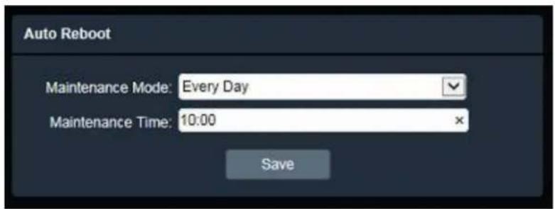
text_image
Auto Reboot Maintenance Mode: Every Day Maintenance Time: 10:00 Save- Every Week: On the selected day, the IP camera will reboot automacally at the specied me (hh:mm).

text_image
Auto Reboot Maintenance Mode: Every Week Weekly Schedule: Sun Mon Tue Wed Thu Fri Sat Maintenance Time: 10:00 Save• One Time: The IP camera will reboot at the specied me (YYYY/MM/DD hh:mm:ss).
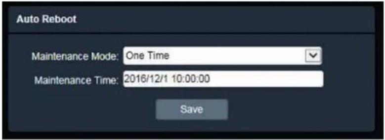
text_image
Auto Reboot Maintenance Mode: One Time Maintenance Time: 2016/12/1 10:00:00 SaveAer complete the sengs, click Save to apply the changes.
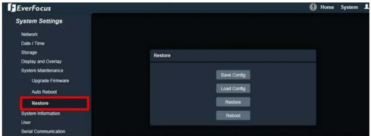
7.1.5.3. Restore
text_image
EverFocus System Settings Network Date / Time Storage Display and Overlay System Maintenance Upgrade Firmware Auto Reboot Restore System Information User Serial Communication Home System Restore Save Config Load Config Restore RebootSave Cong: To make a backup le of the machine's current conguraons, click this buon to export all the conguraons to a conguraon le. This will enable the user to reload these conguraon sengs if the sengs are changed and there is unexpected behavior.
Load Cong: Click to import a previously prepared conguraon le and then apply the parameters from the conguraon le to the system.
Restore: This buon should be used with cauon. Clicking this button will return the selected camera sengs to the factory default values.

text_image
Restore ✓ All ✓ Network Parameters ✓ Account Settings ✓ Alarm & Exception ✓ Miscellaneous OK CancelReboot: Click to reboot the IP camera without changing any of the setngs. Use this funcon if the IP camera is not behaving as expected.
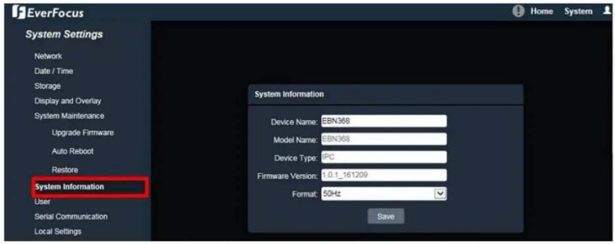
7.1.6. System Informaon
You can check the system informaon or set up NTSC / PAL on this page.
text_image
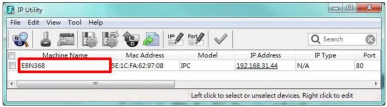
EverFocus System Settings Network Date / Time Storage Display and Overlay System Maintenance Upgrade Firmware Auto Reboot Restore System Information User Serial Communication Local Settings System Information Device Name: EBN368 Model Name: EBN368 Device Type: IPC Firmware Version: 1.0.1_161209 Format: 50Hz SaveDevice Name: If required, enter a desired name for the machine. This name will be visible in the Machine Name eld of the IP Ulity soware.
text_image
IP Utility File Edit View Tool Help Machine Name Mac Address Model IP Address IP Type Port EBN368 5E:1C:FA:62:97:08 IPC 192.168.31.44 N/A 80 Left click to select or unselect devices. Right click to editModel Name: Display the model name of the camera. The values cannot be changed on this page. Device Type: Display the device type. The values cannot be changed on this page.
Firmware Version: Display the current soware version. The values cannot be changed on this page. Format: Select NTSC (60Hz) or PAL (50Hz) for your local scanning system.
Note: Modifying the Format will cause the system to reboot automacally. Please create a new network conncon to the IP camera when the reboot is complete.
Aer complete the sengs, click Save to apply the changes.
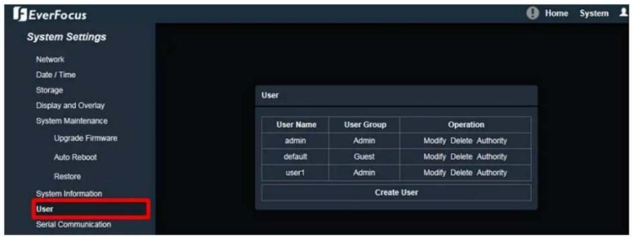
7.1.7. User
The system administrator can create user accounts on this page.
text_image
EverFocus System Settings Network Date / Time Storage Display and Overlay System Maintenance Upgrade Firmware Auto Reboot Restore System Information User Serial Communication User User Name User Group Operation admin Admin Modify Delete Authority default Guest Modify Delete Authority user1 Admin Modify Delete Authority Create UserTo add a user account:
- Click the Create User button and the following dialog box appears.
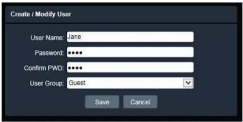
text_image
Create / Modify User User Name: Jane Password: ••••• Confirm PWD: ••••• User Group: Guest Save Cancel- Type the user name and password for the account. Type the password again in the Conrm PWD eld.
- Select an authority level for the user account from the User Group drop-down list. The default authority for each group is listed below. You can sll congure the privileges for each account by clicking Authority.
| Default Authority | Admin | Guest | Operator |
| Remote PTZ | Yes | - | Yes |
| Remotely Playback | Yes | Yes | Yes |
| Remote Parameter Seng | Yes | - | - |
| Remotely Query Log | Yes | Yes | Yes |
| Remotely Upgrade and Format | Yes | - | Yes |
| Remote 2-Way Audio | Yes | - | Yes |
| Remote Live View | Yes | Yes | Yes |
| Remotely Reboot | Yes | Yes | Yes |
Note: Mulple Guest / Operator account can be congured, but only one Admin account can be created for an IP camera.
- Click Save to add the user account.
To modify a user account:
- Click the Modify buon in the Operaon column. The following dialog box appears.
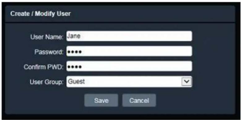
text_image
Create / Modify User User Name: Jane Password: ••••• Confirm PWD: ••••• User Group: Guest Save Cancel- Edit the user name and password for the account. Type the password again in the Conrm PWDeld.
- Edit the authority level for the user account from the User Group drop-down list.
- Click Save to save all the sengs.
To delete a user account:
- Click the Delete button in the Operaon column. The following dialog box appears. The following dialog box appears.

text_image
Message Are you sure to delete this user? OK Cancel- Click OK to delete the user account.
To set up privileges for a user account:
- Click the Authority buon in the Operaon column. The following dialog box appears.

text_image
Authority + Remote PTZ + Remotely Playback + Remote Parameter Setting + Remotely Query Log + Remotely Upgrade and Format + Remote 2-Way Audio + Remote Live View + Remotely Reboot Save-
Check the box to grant the privileges to this user account.
-
Click Save to save all the sengs.
Aer complete the sengs, click Save to apply the changes.
7.1.8. Serial Communicaon
The funcon is currently reserved.
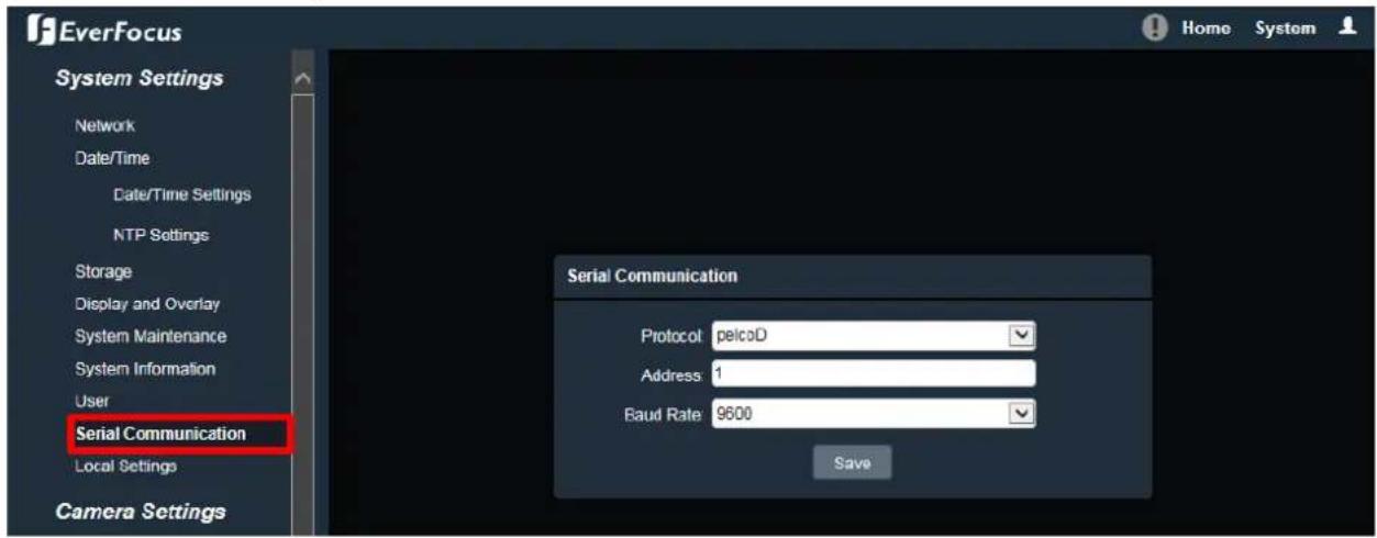
text_image
EverFocus System Settings Network Date/Time Date/Time Settings NTP Settings Storage Display and Overlay System Maintenance System Information User Serial Communication Local Settings Camera Settings Serial Communication Protocol pelcoD Address 1 Baud Rate 9600 SaveProtocol: Select a protocol from Pelco-D or Pelco-P.
Address: Enter the address from 0 to 255.
Baud Rate: This eld is to set the speed at which is used to transmit instrucon or informaon through the RS-485 port (reserved) on the video encoder. There are six dierent speeds, from 50 to 115200.
Aer complete the sengs, click Save to apply the changes.
7.1.9. Local Sengs
You can congregate the storage path for storing the recordings / snapshot on your PC.
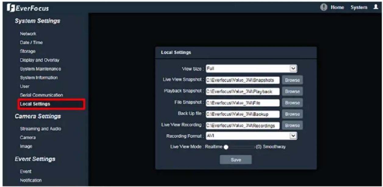
text_image
EverFocus System Settings Network Date / Time Storage Display and Overlay System Maintenance System Information User Serial Communication Local Settings Camera Settings Streaming and Audio Camera Image Event Settings Event Notification Local Settings View Size: Full Live View Snapshot: C:\Everfocus\Value_3M\Snapshots Browse Playback Snapshot: C:\Everfocus\Value_3M\Playback Browse File Snapshot: C:\Everfocus\Value_3M\File Browse Back Up file: C:\Everfocus\Value_3M\Backup Browse Live View Recording: C:\Everfocus\Value_3M\Recordings Browse Recording Format: AV1 Live View Mode: Realtime ● (0) Smoothway SaveView Size: Select the appropriate view size of the live view window.
Live View Snapshot: Type the storage path for snapshots captured in the Home page (Live View window).
Playback Snapshot: Type the storage path for snapshots captured in the Playback page.
File Snapshot: Type the storage path for snapshots captured in the File page.
Backup le: Type the storage path for recording les backed up in the Playback page.
Live View Recording: Type the storage path for recordings recorded in the Home page (Live View window).
Record Format: Currently only AVI is available.
Live View Mode: Slide the bar to set up the live stream performance between Real Time and Smooth way.
Aer complete the sengs, click Save to apply the changes.
Note: The Playback related sengs are only functional if the micro SD Card has been inserted in the camera's micro SD card slot.
7.2. Camera Sengs
You can congregate camera related sengs, such as video, audio, image and privacy mask.
7.2.1. Streaming and Audio
7.2.1.1. Audio Sengs
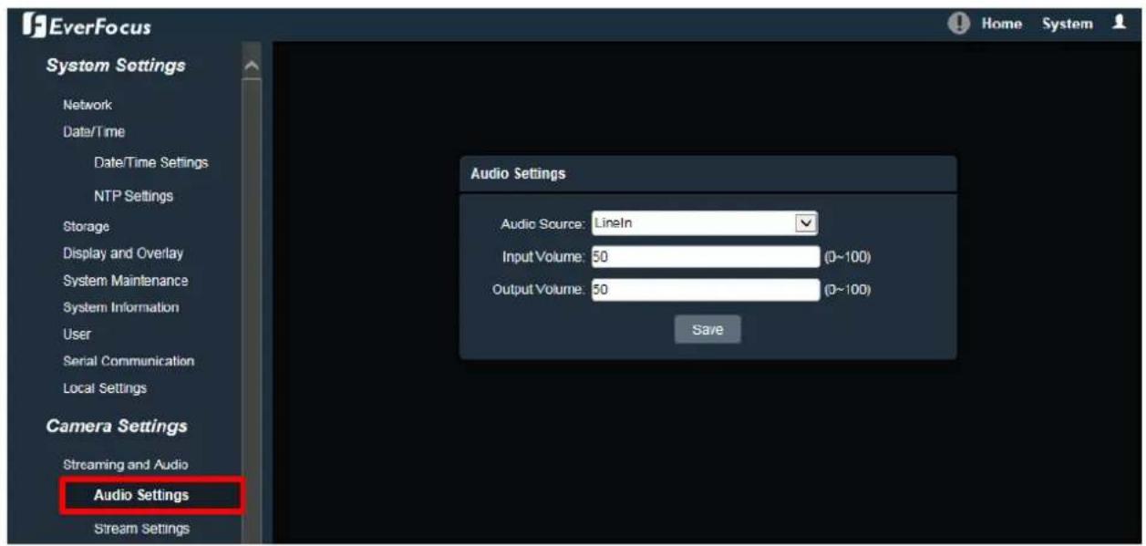
text_image
EverFocus System Settings Network Date/Time Date/Time Settings NTP Settings Storage Display and Overlay System Maintenance System Information User Serial Communication Local Settings Camera Settings Streaming and Audio Audio Settings Stream Settings Audio Settings Audio Source: LineIn Input Volume: 50 (0~100) Output Volume: 50 (0~100) SaveThe camera can transmit audio to your computer if you have connected an external line-in audio device to its audio Input. Select an audio source (currently only Line-in is available) then adjust the audio input / output volume. Note that the camera provides the line-in / out audio ports, therefore, microphones / speakers with an (built-in) amplifier and external power supply are required.
Aer complete the sengs, click Save to apply the changes.
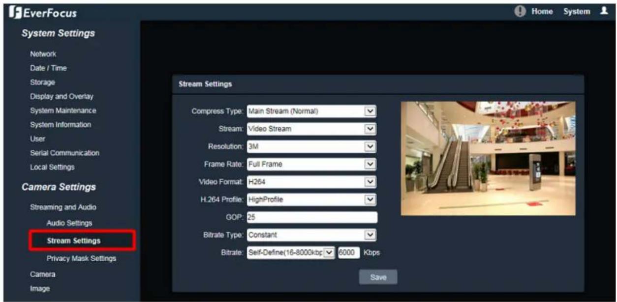
7.2.1.2. Stream Sengs
text_image
EverFocus System Settings Network Date / Time Storage Display and Overlay System Maintenance System Information User Serial Communication Local Settings Camera Settings Streaming and Audio Audio Settings Stream Settings Privacy Mask Settings Camera Image Stream Settings Compress Type: Main Stream (Normal) Stream: Video Stream Resolution: 3M Frame Rate: Full Frame Video Format: H264 H.264 Profile: HighProfile GOP: 25 Bitrate Type: Constant Bitrate: Self-Define(16-8000kbp) 6000 Kbps SaveCompress Type: Select from Main Stream or Sub Stream.
Stream: Select from Video Stream (video only) or Complex Stream (video & audio).
Resoluon: Select the most suitable resoluon for your needs.
Frame Rate: Select from 1fps to Full Frame. The default frame rate is Full Frame.
Video Format: Select the encoding format – H.265 or H.264.
H264 Prole: Select the video coding level from Main Prole, Baseline or High Prole.
GOP: Enter the I-frame interval me from 2 to 255 to adjust the frequency of generang I-frames per second.
Bitrate Type: If required, select whether you want the stream to stream a Constant Bit Rate or a Variable Bit Rate, and set the values of whichever opon you choose.
Bitrate: For Constant Bit Rate only. Select the desired Bit Rate from the drop-down list or enter a customized Constant Bit Rate (16 to 8000 kbit) in the ☐ Kbps eld.
Max Bitrate: For Variable Bit Rate only. Select the desired Max Bit Rate from the drop-down list or enter a customized Max Bit Rate (16 to 8000 kbit) in the □ Kbps eld.
Quality: For Variable Bit Rate only. Select the desired front end devices video coding quality, from Lowest to Highest.
Aer complete the sengs, click Save to apply the changes.
Note: If you connect to the camera via the Internet and experience a delay (lag me) in the video feed, try to reduce the quality and resolution of the streams – but keep the frame rate at its maximum.
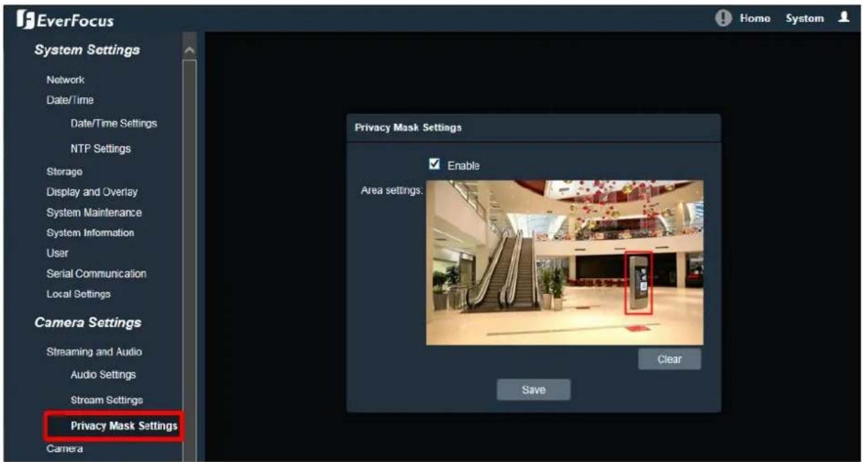
7.2.1.3. Privacy Mask Sengs
The Privacy Mask can block out sensitive areas from view, covering the areas with black boxes in both live view and recorded clips. This feature is useful when users' don't want the sensitive informaon visible. Up to four Privacy Masks can be congured.
text_image
EverFocus System Settings Network Date/Time Date/Time Settings NTP Settings Storage Display and Overlay System Maintenance System Information User Serial Communication Local Settings Camera Settings Streaming and Audio Audio Settings Stream Settings Privacy Mask Settings Camera Privacy Mask Settings Enable Area settings. Clear SaveTo set up a Privacy Mask:
- Check the Enable box to enable the Privacy Mask funcon.
- In the Area Sengs eld, move the cursor to the posion where you want the mask rectangle to start and then click it. Move the cursor to the posion (diagonally opposing corner) where you want the mask rectangle to end and then click it.
- You can remove the congured mask by clicking the Clear buon.
Aer complete the sengs, click Save to apply the sengs.
7.2.2. Camera

text_image
EverFocus System Settings Network Date / Time Storage Display and Overlay System Maintenance System Information User Serial Communication Local Settings Camera Settings Streaming and Audio Camera Image Event Settings Event Notification Search and Play Playback File Log Camera Day/Night Mode Mode: Auto (Light sensor) Switching time: 0 (0-30) Day to Night: 20 (0-255) Night to Day: 85 (0-255) Light Board Control Mode: Auto Brightness: 0 (0-100) Advanced Settings TWDR: OFF 3DNR: Low Defog: OFF Slow Shutter: OFF Exposure Settings Mode: Auto (AGC) Manual AGC: Low Shutter: 1/30(1/25) Save Aperture Lens: Manual Semiautomatic Gamma Gamma: CURVE_2_2 Flickerless: OFFDay/Night Mode
Mode: Select a mode from the drop-down list. The default Day/Night mode is Auto(Light sensor).
- Auto(Light sensor): Select to let the camera automacally switch to Day mode (color images) or Night mode (black and white images with IR LED on) based on the light sensor's detecon on the light level.
- Auto(AGC): Select to let the camera automacally switch to Day mode (color images) or Night mode (black and white images with IR LED on) based on the AGC value of the current video image.
- Color: Select to keep the camera in Day mode (color images with IR LED o), even in nighme.
- Black White: Select to keep the camera in Night mode (black and white images with IR LED on), even in dayme.
Switching Time: Select the transition duraon a switching will take for Auto(AGC) Day/Night Mode, from 0 to 30 second(s). The default switching me is 3 seconds.
Day to Night: You can congregate the sensitivity for Auto(AGC) Day/Night Mode ranging from 0-255. The camera will automatically switch from day mode to night mode based on the setup sensitivity. The default value is 20.
Night to Day: You can congregate the sensitivity for Auto(AGC) Day/Night Mode ranging from 0-255. The camera will automatically switch from night mode to day mode based on the setup sensitivity. The default value is 35.
Light Board Control
Mode: Select a mode (OFF, Manual, Auto) from the drop-down list. The default Light Board Control mode is OFF.
Brightness: You can congregate the brightness for Manual Light Board Control Mode.
Advanced Sengs
TWDR (True Wide Dynamic Range): The WDR funcon provides clearer images when both of the very bright and dark areas simultaneously appear on the camera view. There are four value opons: OFF, Low, Mid and High. Note that when WDR is enabled, some parts of the image may appear solarized. This is normal for WDR, and is not a camera malfuncon. The default TWDR mode is OFF.
3DNR (3D Noise Reducon): Noise Reducon limits the amount of digital “video noise” that is usually found in any video stream, and helps to reduce le size. There are ve value opons: OFF, Low, Mid, Mid-High and High. The default 3DNR mode is Low.
Defogging: The Defog funcon makes the subject appear clearer when the surrounding area of the subject is foggy and low contrast. There are four value opons: OFF, Low, Mid and High. The default defogging mode is OFF.
Slow Shuer: Select from OFF or ON.
Note: Modifying the TWDR mode will cause the system to reboot automacally. Please create a new network conncon to the IP camera when the reboot is complete.
Exposure Control
Mode: Select a mode from Auto or Manual. The default Exposure mode is Auto.
- Auto(AGC): Selecng Auto for the camera to automacally adjust the Shutter based on the measured light level. You can further conjure the AGC value.
- Manual: Select this opon to manually set up the Shuer value.
AGC: For Auto(AGC) Exposure mode, you can further conjure the AGC value. Select the Auto Gain Control level from Low to High. The lower the AGC level, the lower the video signal and the noise. The higher the AGC level, the beer the sensitivity under low illuminaon, while the noise will be more obvious. The default AGC level is Mid-High.
Shuer: For Manual Exposure mode, you can further conjure the Shuer value. If enabled, this seng lets you set the shuer speed yourself (measured in fracons of a second).
Aperture
Lens: Select a mode from Manual or Semiautomac. The default Iris mode is Semiautomac.
Note: The Aperture funcon is only available for EDN288/368M and EZN288/368M.
Gamma
Gamma: Users can use this eld to optimize video quality of the monitor. Choose CURVE_1_6, CURVE_1_8, CURVE_2_0 or CURVE_2_2 from the drop down list. The darker the environment is, the higher Gamma value you should choose. The default Gamma mode is CURVE_2_0.
Flikerless: Choose between OFF, 50HZ or 60HZ. The default Flikerless mode is OFF.
Aer complete the sengs, click Save to apply the changes.
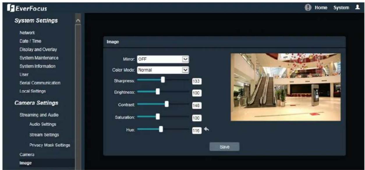
7.2.3. Image
text_image
EverFocus System Settings Network Date / Time Display and Overlay System Maintenance System Information User Serial Communication Local Settings Camera Settings Streaming and Audio Audio Settings Stream Settings Privacy Mask Settings Camera Image Mirror: OFF Color Mode: Normal Sharpness: 133 Brightness: 100 Contrast: 148 Saturation: 100 Hue: 116 SaveMirror: Select a mirror mode from OFF, Horizontal Mirror, Vercal Mirror, 180 degree Rotaon, 90 degree Rotaon or 270 degree Rotaon. The default Mirror mode is Close.
• Horizontal Mirror: The image will be rotated horizontally around a vercal axis.
• Vercal Mirror: The image will be rotated vercally around a horizontal axis.
• 180 degree Rotaon: The image will be rotated 180 degree.
• 90 degree Rotaon: The image will be rotated 90 degree.
• 270 degree Rotaon: The image will be rotated 270 degree.
Note: Set up 90 / 180 / 270 degree rotaon will cause the system to reboot automacally. Please create a new network conncon to the IP camera when the reboot is complete.
Color Mode: Select a color mode from Normal, Bright or Nature. The default color mode is Normal.
Sharpness: Slide the bar to adjust the sharpness.
Brightness: Slide the bar to adjust the brightness.
Contrast: Slide the bar to adjust the contrast.
Saturaon: Slide the bar to adjust the saturaon.
Hue: Slide the bar to adjust the hue.
Click the Default buon

to return the color setngs (Bright, Contrast, Saturaon and Hue) to
the default value.
Aer complete the sengs, click Save to apply the changes.
7.3. Event Sengs
You can set up the Moon Detecon event or Tampering Detecon event to automacally nofy the users when an event occurs.
7.3.1. Event
7.3.1.1. Moon Sengs
Use this page to congregate the area in which moon will be detected, and set up schedules to acve alarm funcons. When a moon is detected by the camera, the alarm icon at the to
at the top
of the Live View window will turn red and blink to alert the user. Up to four Moon areas can be congured.

text_image
EverFocus NTP Settings Storage Display and Overlay System Maintenance System Information User Serial Communication Local Settings Camera Settings Streaming and Audio Audio Settings Stream Settings Privacy Mask Settings Camera Image Event Settings Event Motion Settings Tamper Detection Setting Alarm Input Alarm Out Exception Settings Motion Settings Enable sensitivity: 4 Week Monday ArmSchedule MaskSet Section1: 0 0 - 23 59 Section2: 0 0 - 0 0 Section3: 0 0 - 0 0 Section4: 0 0 - 0 0 Section5: 0 0 - 0 0 Section6: 0 0 - 0 0 Section7: 0 0 - 0 0 Section8: 0 0 - 0 0 LinkType Email: Snapshot Record Alarm Output Snapshot Interval: 1 Snapshot No.: 1 SaveTo set up a Moon Detecon area:
- Check the Enable box to enable the Moon Detecon funcon. Select a value from the drop-down list to set the sensitivity of the Moon Detecon.
-
Select a day (Monday \~ Sunday) from the Week drop-down list to conjure the schedule.
-
Set up schedules to acve the alarm funcons and send alarm nocacn. Check the box of the desired secon to congrure the schedule, and select a start / end me from the drop-down list for the secon.
- On the preview window, click and drag to draw the desired Moon Detect area, the area will be marked in red.
- You can remove the congured Moon Detecon area by clicking the Clear button.
- Set up event reacons for the Moon Detecon funcon. Check the box of the desired reacon (Email, Snapshot, Record or Alarm output) to link with the funcon.
Email: Check the box to enable transming the alarm nocao on to the mail server. To congure Email sengs, see 7.3.2.1 Email Sengs.
Snapshot: Check the box to enable taking snapshots to the micro SD Card when an event occurs. You can further conjure the Snapshot sengs including Snapshot Interval and Snapshot No.. For example, if you set up the Snapshot Interval to 5 and Snapshot No. to 3, system will take 3 snapshots every 5 seconds.
Record: Check the box to enable recording to the micro SD Card when an event occurs.
Alarm Output: Check the box to enable triggering the external alarm device.
Aer complete the sengs, click Save to apply the sengs.
Note: The Snapshot and Record sengs are only functional if the micro SD Card has been inserted in the camera's micro SD card slot.
7.3.1.2. Tamper Detecon Sengs
Use this page to congregate the area in which tampering will be detected and set up schedules to acve alarm funcons. When a tampering is detected by the camera, the alarm icon at the
top of the Live View window will turn red and blink to alert the user.
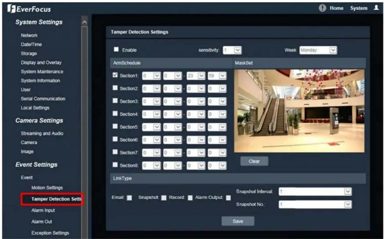
text_image
EverFocus System Settings Network Date/Time Storage Display and Overlay System Maintenance System Information User Serial Communication Local Settings Camera Settings Streaming and Audio Camera Image Event Settings Event Motion Settings Tamper Detection Setti Alarm Input Alarm Out Exception Settings Tamper Detection Settings Enable sensitivity: 1 Week Monday ArmSchedule MaskSet Section1: 0 0 - 23 59 Section2: 0 0 - 0 0 Section3: 0 0 - 0 0 Section4: 0 0 - 0 0 Section5: 0 0 - 0 0 Section6: 0 0 - 0 0 Section7: 0 0 - 0 0 Section8: 0 0 - 0 0 Clear LinkType Email: Snapshot Record Alarm Output: Snapshot Interval: 1 Snapshot No.: 1 SaveTo set up a Tampering Detecon area:
- Check the Enable box to enable the Tampering Detecon funcon. Select a value from the drop-down list to set the sensitivity of the Tampering Detecon.
- Select a day (Monday \~ Sunday) from the Week drop-down list to congregate the schedule.
- Set up schedules to acve the alarm funcons and send alarm nocacn. Check the box of the desired secon to congure the schedule, and select a start / end me from the drop-down list for the secon.
- On the preview window, click and drag to draw the desired Tampering Detecon area, the area will be marked in red.
- You can remove the congured Tampering Detecon area by clicking the Clear buon.
- Set up event reacons for the Tampering Detecon funcon. Check the box of the desired reacon (Email, Snapshot, Record or Alarm output) to link with the funcon.
Email: Check the box to enable transmitting the alarm nocaon to the mail server. To congure Email sengs, see 7.3.2.1 Email Sengs.
Snapshot: Check the box to enable taking snapshots to the micro SD Card when an event occurs. You can further conjure the Snapshot sengs including Snapshot Interval and Snapshot No.. For example, if you set up the Snapshot Interval to 5 and Snapshot No. to 3, system will take 3 snapshots every 5 seconds.
Record: Check the box to enable recording to the micro SD Card when an event occurs.
Alarm Output: Check the box to enable triggering the external alarm device.
Aer complete the sengs, click Save to apply the sengs.
Note: The Snapshot and Record sengs are only functional if the micro SD Card has been inserted in the camera's micro SD card slot.
Use this page to congregate the alarm input channel in which event will be triggered and set up schedules to acve alarm funcons. When an event is triggered by the alarm input, the alarm
icon ⚠️ at the top of the Live View window will turn red and blink ⚠️ to alert the user.
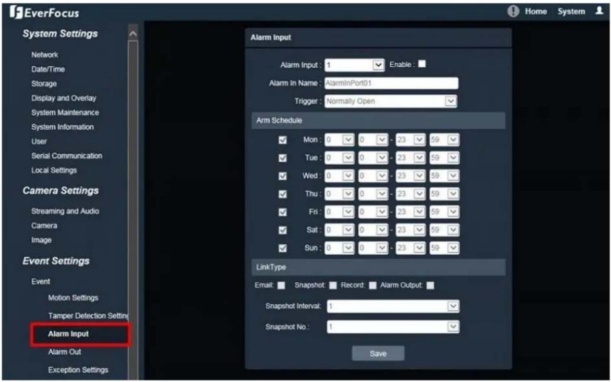
text_image
EverFocus System Settings Network Date/Time Storage Display and Overlay System Maintenance System Information User Serial Communication Local Settings Camera Settings Streaming and Audio Camera Image Event Settings Event Motion Settings Tamper Detection Setting Alarm Input Alarm Out Exception Settings Alarm Input 1 Enable : Alarm In Name : AlarmInPort01 Trigger : Normally Open Arm Schedule Mon : 0 0 - 23 59 Tue : 0 0 - 23 59 Wed : 0 0 - 23 59 Thu : 0 0 - 23 59 Fri : 0 0 - 23 59 Sat : 0 0 - 23 59 Sun : 0 0 - 23 59 LinkType Email: Snapshot Record Alarm Output Snapshot Interval: 1 Snapshot No.: 1 SaveTo set up the Alarm Input funcon:
- Select a camera's Alarm Input channel from the drop-down list and check the Enable box to enable this channel. Aer enabling this channel, you can further congregate the Alarm Input schedules and event reacons.
- Enter a name for the Alarm Input channel in the Alarm Input Title eld (the name will show up in the event nocaons and logs) and select Normally Open or Normally Close from the Trigger Type drop-down list.
- Set up schedules to acve the alarm funcons and send alarm nocacn. Check the box of the desired day (Monday \~ Sunday) to congure the schedule, and select a start / end me from the drop-down list for each day.
- Set up event reacons for the Alarm Input channel. Check the box of the desired beacon (Email, Snapshot, Record or Alarm output) to link with the funcon.
Email: Check the box to enable transmitting the alarm nocao on to the mail server. To congure Email sengs, see 7.3.2.1 Email Sengs.
Snapshot: Check the box to enable taking snapshots to the micro SD Card when an event occurs. You can further conjure the Snapshot sengs including Snapshot Interval and Snapshot No.. For example, if you set up the Snapshot Interval to 5 and Snapshot No. to 3, system will take 3 snapshots every 5 seconds.
Record: Check the box to enable recording to the micro SD Card when an event occurs.
Alarm Output: Check the box to enable triggering the external alarm device.
Aer complete the sengs, click Save to apply the sengs.
Note: The Snapshot and Record sengs are only functional if the micro SD Card has been inserted in the camera's micro SD card slot.
7.3.1.4. Alarm Output
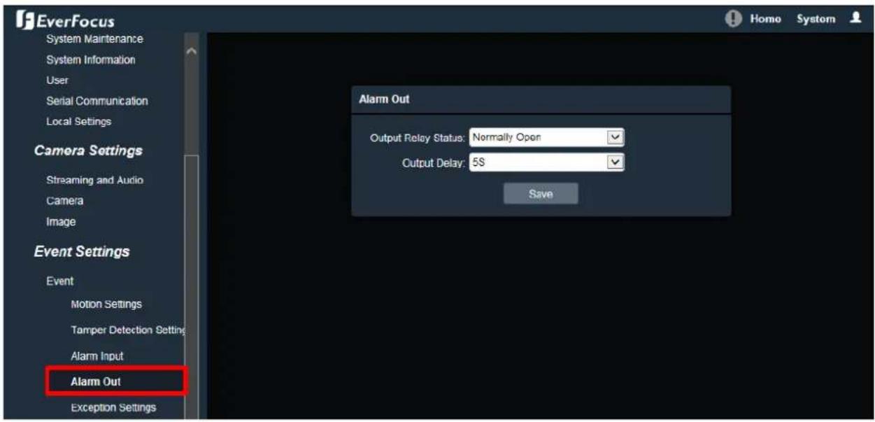
text_image
EverFocus System Maintenance System Information User Serial Communication Local Settings Camera Settings Streaming and Audio Camera Image Event Settings Event Motion Settings Tamper Detection Setting Alarm Input Alarm Out Exception Settings Alarm Out Output Relay Status: Normally Open Output Delay: 5S SaveOutput Relay Status: Select Normally Open or Normally Close from the drop-down list.
Output Delay: Select the duraon (5 seconds - 10 minutes) for the buffer. This will determine the length of me aer the event trigger moment that the external alarm device will keep alarming.
Aer complete the sengs, click Save to apply the sengs.
7.3.1.5. Excepon Sengs
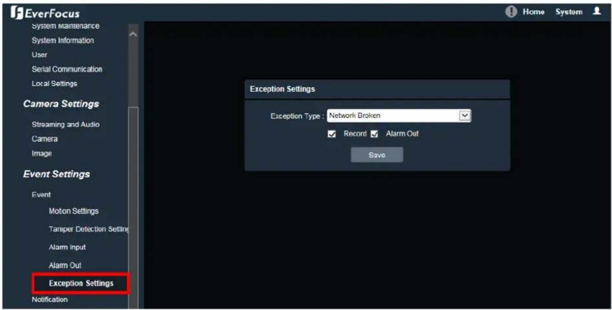
text_image
EverFocus System Maintenance System Information User Serial Communication Local Settings Camera Settings Streaming and Audio Camera Image Event Settings Event Motion Settings Tamper Detection Setting Alarm Input Alarm Out Exception Settings Notification Exception Settings Exception Type: Network Broken Record Alarm Out SaveExcepon Type: Select an excepon type from Network Broken, IP Address Conict or Illegal Access.
Record: Check the box to enable recording to the micro SD Card when an event occurs.
Alarm Output: Check the box to enable triggering the external alarm device.
Aer complete the sengs, click Save to apply the sengs.
Note: The Record seng is only functional if the micro SD Card has been inserted in the camera's micro SD card slot.
7.3.2. Nocaon
7.3.2.1. Email Sengs
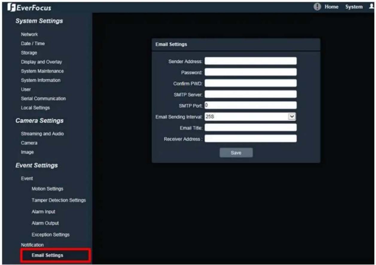
text_image
EverFocus System Settings Network Date / Time Storage Display and Overlay System Maintenance System Information User Serial Communication Local Settings Camera Settings Streaming and Audio Camera Image Event Settings Event Motion Settings Tamper Detection Settings Alarm Input Alarm Output Exception Settings Notification Email Settings Email Settings Sender Address: Password: Confirm PWD: SMTP Server: SMTP Port: 0 Email Sending Interval: 25S Email Title: Receiver Address: SaveSender Address: Input the sender's e-mail address, so that the receiver can recognize the sender when an event message is received.
Password: Input the user's login password if the SMTP server requires authencaon.
Conrm PWD: Type the password again to conrm it.
SMTP Server: Enter the IP address or the host name of the SMTP server used to send e-mails.
SMTP Port: Enter the port number for SMTP.
Email Sending Interval: Input the interval me for sending e-mail nocaaon.
Email Title: Type the e-mail tle.
Receiver Address: Input the e-mail addresses for receiving an e-mail message when events occur. Currently only one receiver address can be congured.
Aer complete the sengs, click Save to apply the sengs.
7.4. Search and Play
You can remotely play back the recordings stored in the on-camera micro SD card in Playback page, or play back the snapshots / recordings stored in the computer in File page.
7.4.1. Playback
Playback is designed as a quick way to check recent event recordings in the on-camera micro SD card.

text_image
EverFocus System Settings Network Date / Time Storage Display and Overlay System Maintenance System Information User Serial Communication Local Settings Camera Settings Streaming and Audio Camera Image Event Settings Event Notification Search and Play Playback File Log 2016-12-20 2016 DEC Run More Tue Wvl Thru Set 4 5 6 7 8 9 10 11 12 13 14 15 16 17 18 19 20 21 22 23 24 25 26 27 28 29 30 31 Search Speed: NormalTo search and then play back the recording:
Check the CH01 box to select the IP camera on the le-side panel, and then select the date you want to search on the right-side panel. Click Search to get your search results. Double-click on the Time Bar to play back from the specied me, or click the Start to play back from the start.

text_image
Speed: NormalStart / Pause: Click
to play the recording le. Click
" to pause playing back.
Stop: Click
to stop playing back.
Slow: Click
to slow down the playback speed (switch between 1/2, 1/4, 1/8 and 1/16).
Fast: Click
to speed up the playback speed (switch between 2, 4, 8 and 16).
Capture: Click

to take a snapshot.
Backup: Click

and a Video Download window will pop up.

text_image
Video Download Channel: 01 Start Time: 2016y 12n 21d 0h 0min 0se End Time: 2016y 12n 21d 11h 32mi 56s Up to: C:\Everfocus\Value_3M\Backup File Format: AVI Backing up the 0 Channel... Progress: 0 Start StopTo back up the recording:
- Check the 01 box to select the IP camera
- Select the Start/End Time for the recordings you want to back up.
- Specify the storage path for the backup les in the Up to column.
- Click Start to download the recording les; click Stop to stop downloading.
Frame Play: Click

to play the recording le frame by frame.
Full Screen: Click

display the current recordings in full screen.
Speed: Display the current playback speed.
Voice: Click

adjust the volume or switch the sound on / o for of the recording.
Note: The Playback page is only accessible if the micro SD Card has been inserted in the camera's micro SD card slot.
7.4.2. File
File is a tool to check all the snapshots, recordings and backup les in the on-camera micro SD card or the local storage.
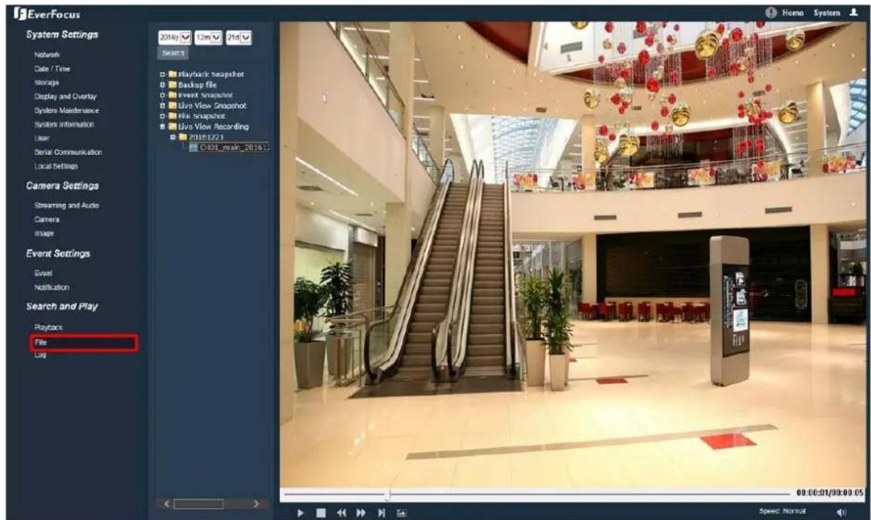
text_image
EverFocus System Settings Network Date / Time Storage Display and Overlay System Maintenance System Information User Serial Communication Local Settings Camera Settings Streaming and Audio Camera Image Event Settings Event Notification Search and Play Playback File Log 2016/ 12m 2nd Search Playback Snapshot Backup file Event Snapshot Live View Snapshot File Snapshot Live View Recording 20161221 C:\01_main_2016\1\. 00:00:01/00:00:05 Speed NormalTo search and then view the snapshot / recording le:
- On the le-side panel, select the date you want to search and then click Search.
- Click the + node of the desired le type to expand the sub-folder (date folder).
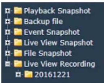
text_image
Playback Snapshot Backup file Event Snapshot Live View Snapshot File Snapshot Live View Recording 20161221- Click the + node of the desired date folder to list all les captured or recorded on this date.

text_image
Live View Recording 20161221 CH01_main_20161:- Double-click on the le to display it.

text_image
Playback Snapshot Backup file Event Snapshot Live View Snapshot File Snapshot Live View RecordingPlayback Snapshot: Click to list all snapshots captured in the Playback page.
Backup le: Click to list all recording les backed up in the Playback page.
Event Snapshot: Click to list all snapshots captured by the triggering of Events.
Live View Snapshot: Click to list all snapshots captured in the Home page (Live View window).
File Snapshot: Click to list all snapshots captured in this (File) page.
Live View Recording: Click to list all recordings recorded in the Home page (Live View window).

text_image
Speed: NormalStart / Pause: Click ▶ to play the le. Click ▶ to pause playing.
Stop: Click to stop playing.
Slow: Click to slow down the play speed (switch between 1/2, 1/4, 1/8 and 1/16)
Fast: Click to speed up the play speed (switch between 2, 4, 8 and 16)
Frame Play: Click to play the recording le frame by frame.
Capture: Click to take a snapshot.
Speed: Display the current speed.
Voice: Click to adjust the volume or switch the sound on / o for of the recording le.
To change the storage path, see 7.1.9 Local Sengs.
Note: The Playback Capture / Backup / Linkage Capture folders are only accessible if the micro SD Card has been inserted in the camera's micro SD card slot.
7.4.3. View Log
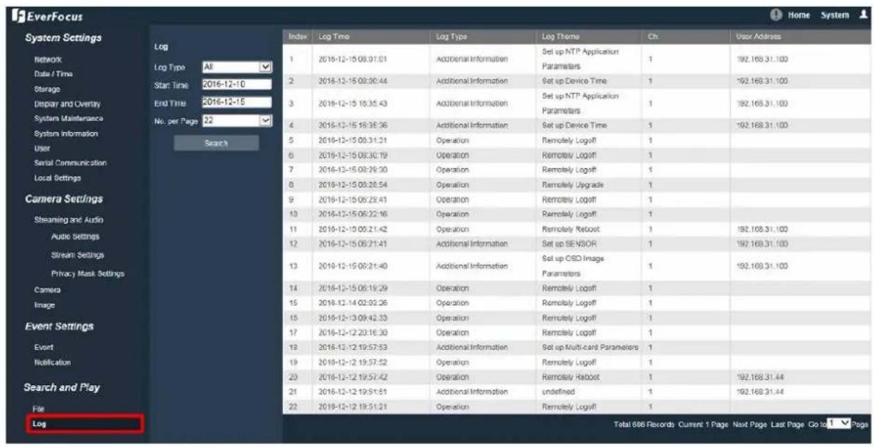
text_image
EverFocus Home System System Settings Log Log Type All Start Time 2016-12-10 End Time 2016-12-15 No. per Page 22 Search Index Log Time Log Type Log Theme Ch User Address 1 2019-12-15 08:31:01 Additional Information Set up NTP Application Parameters 1 192.168.31.100 2 2018-12-15 08:30:44 Additional Information Set up Device Time 1 192.168.31.100 3 2019-12-15 18:35:43 Additional Information Set up NTP Application Parameters 1 192.168.31.100 4 2018-12-15 18:35:36 Additional Information Set up Device Time 1 192.168.31.100 5 2019-12-15 08:31:31 Operation Remotely Logoff 1 6 2019-12-15 08:30:19 Operation Remotely Logoff 1 7 2016-12-15 09:29:30 Operation Remotely Logoff 1 8 2019-12-15 09:28:54 Operation Remotely Upgrade 1 9 2019-12-15 09:25:41 Operation Remotely Logoff 1 10 2016-12-15 09:22:46 Operation Remotely Logoff 1 11 2019-12-15 09:21:42 Operation Remotely Reboot 1 192.108.31.100 12 2016-12-15 09:21:41 Additional Information Set up SENSOR 1 192.168.31.100 13 2019-12-15 09:21:40 Additional Information Set up OSO Image Parameters 1 192.168.31.100 14 2016-12-15 09:19:29 Operation Remotely Logoff 1 15 2018-12-14 09:03:26 Operation Remotely Logoff 1 16 2019-12-13 09:42:33 Operation Remotely Logoff 1 17 2016-12-12 09:36:30 Operation Remotely Logoff 1 18 2018-12-12 09:57:53 Additional Information Set up Multi-card Parameters 1 19 2019-12-12 09:57:52 Operation Remotely Logoff 1 20 2016-12-12 09:57:42 Operation Remotely Reboot 1 192.168.31.44 21 2018-12-12 09:57:51 Additional Information undefined 1 192.168.31.44 22 2019-12-12 09:57:54 Operation Remotely Logoff 1 Total 686 Records Current 1 Page Next Page Last Page Go to 7 PageTo search the system log:
- On the le-side panel, click on the Main Type drop-down list to select a log type from All, Alarm, Excepon Sengs, Operaon and Setup.
- Click on the Start/End Time column to bring up the calendar and then select a start/end date.
- Click the Search buon, the search result will be displayed in the right part of the page.
- You can specify how many logs to display on each page in the No. per Page column.
8. Upgrading Firmware Using IP Utility
You can upgrade the Firmware using the IP Utility soware included in the soware CD. The IP Utility can also be downloaded from EverFocus' Website:
hp://www.everfocus.com.tw/HQ/Support/DownloadCenter_p1.aspx (Support > Download Center > Keyword Search: IP Utility). Please connect the IP camera on the same LAN of your computer.
- Install and then start the IPU program 📄, the following IPU window appears. The IPU will automatically search the IP devices connected in the LAN.
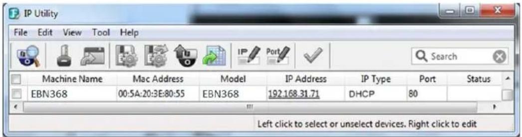
text_image
IP Utility File Edit View Tool Help Machine Name Mac Address Model IP Address IP Type Port Status EBN368 00:5A:20:3E:80:55 EBN368 192.168.31.71 DHCP 80 Left click to select or unselect devices. Right click to edit- Log in the camera by checking the desired model and then click the Log in icon. The Log in dialog box appears.
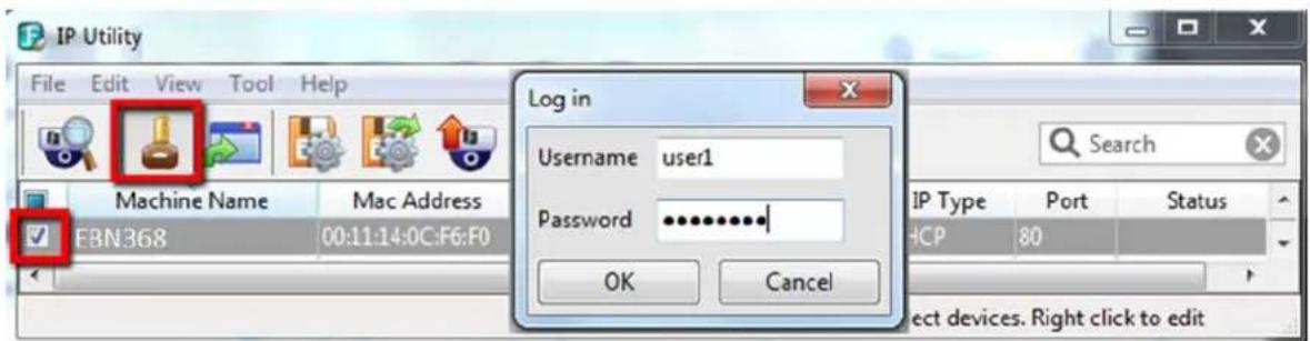
text_image
IP Utility File Edit View Tool Help Machine Name Mac Address EBN368 00:11:14:0C:F6:F0 Log in Username user1 Password ********* OK Cancel Search IP Type Port Status HCP 80 Select devices. Right click to edit- Type the Username and Password. Click the OK button, the Login status displays.
| Machine Name | Mac Address | Model | IP Address | IP Type | Port | Status |
| EBN368 | 00:11:14:12:30:A4 | EBN368 | 192.168.31.67 | DHCP | 80 | Login |
Note:
- The default user ID is user1 and the default password is 11111111.
- If you select more than one camera that has the same user ID / password, you will be able to log in several cameras at once.
- Up to 10 cameras can be simultaneously upgraded to the latest rmware. If you connect the cameras to a PoE switch, please make sure the Power Consumpon of the PoE switch is sucient.
4. Click the Upgrade Firmware buon

browsing window appears.

text_image
Select a firmware file Look in: Firmware exn-1.2.4.evbl File name: Files of type: Firmware File (*.evbl) Open Cancel- Select the rmware le (.evb) and then click Open. The IPU will automacally upgrade the rmware. The camera will reboot once the upgrade process is complete.
| Machine Name | Model | IP Address | IP Type | Port | Status | |
| √ | EBN368 | EBN368 | 192.168.31.215 | Static IP | 80 | Success |
- Specicaons
| Model | EBN288/368 | EDN288/368M | EZN288/368 | EZN288/368M |
| Camera | ||||
| Megapixel | 288 Series: 2MP ; 368 Series : 3MP | |||
| Pickup Device | Sony Progressive Scan CMOS sensor | |||
| Min. Illuminaons | Color: 0.05Lux @ F1.4;B/W: 0.005Lux @ F1.4 | Color: 0.05Lux @ F1.4;B/W: 0.005Lux @ F1.4 | Color: 0.05Lux @ F1.4;B/W: 0.005Lux @ F1.4 | Color: 0.05Lux @ F1.4;B/W: 0.005Lux @ F1.4 |
| Day/Night | True Day/Night with ICR | |||
| Shuer Time | 1/25 ~ 1/10,000 | |||
| Scanning System | NTSC / PAL | |||
| WDR | True Wide Dynamic Range Funcon (120dB) | |||
| AGC | Yes | |||
| AWB | Yes | |||
| Lens | ||||
| Lens | 3.6mm xed lens | Motorized 2.8-12mm lens | 3.6mm xed lens | Motorized 2.8-12mm lens |
| Lens Angle of View | - | Horizontal 150°, Vercal 75° | Horizontal 360°, Vercal 90° | Horizontal 90°, Vercal 180° |
| Day/Night | True Day/Night with ICR | |||
| IR Distance | 30m / 100. | 30m / 100. | 30m / 100. | 30m / 100. |
| IR LED Quanty | 18 | 12 | 15 | 3 (High Power IR LEDs) |
| IRIS | Fixed Iris | Fixed Iris | Fixed Iris | Fixed Iris |
| Video | ||||
| Video Compression | H.265 / H.264 | |||
| Max. Video Resoluon | 288 Series: 1920 x 1080 ; 368 Series : 2048 x 1536 | |||
| Frame Rate | 25fps / 30fps | |||
| S/N Rao | ≥ 50db (AGC OFF) | |||
| Image Sengs | Contrast, Brightness, Saturaon, Sharpness, Mirroring of Images | |||
| Audio | ||||
| Audio Compression | G.711A / 64Kbps / Two-way audio* | |||
| Audio Input / Output | 1 In (Line-in 3.5mm stereo TRS jack)*1 Out (Line-out 3.5mm stereo TRS jack)* | |||
| Network | |||||
| Interface | RJ-45 10M/100M adapve | ||||
| Supported Protocols | TCP/IP, UDP, HTTP, DHCP, RTSP, DDNS, NTP, PPPOE, UPNP, SMTP, ONVIF | ||||
| Connector | Power | 12VDC, PoE | |||
| Ethernet | RJ-45 | ||||
| Event / Nocaon | |||||
| Event Trigger | Moon Detecon | ||||
| Nocaon | Email Nocaon | ||||
| General | |||||
| Storage | - | Micro SD / SDHC / SDXC slot (Max. 128G, up to class 10) | Micro SD / SDHC / SDXC slot (Max. 128G, up to class 10) | Micro SD / SDHC / SDXC slot (Max. 128G, up to class 10) | |
| RS-485 | RS-485 x 1 (reserved)* | ||||
| Alarm Input / Output | 2 / 1* | ||||
| Video Output | Video test output cable* | ||||
| Power Supply | 12VDC / PoE (IEEE802.3af Class 3) | ||||
| Max. Power Consumpon (IR LEDs on) | 12VDC 5.2W / PoE 5.8W | 12VDC 4.5W / PoE 4.9W | 12VDC 3.5W / PoE 3.9W | 12VDC 7.4W / PoE 8.2W | |
| Water Proof | IP66 | ||||
| Humidity | 0% ~ 90% not condensing | ||||
| Operang Temperature | -10°C ~ 50°C / 14°F ~ 122°F | ||||
| Dimensions | 120 x 95mm / 4.72" x 3.74" | 117 x 86mm / 4.61" x 3.39" | 186 x 71mm / 7.32" x 2.80" | 263 x 93mm / 10.35" x 3.66" | |
| Weight | 740g / 1.63lb | 660g / 1.46lb | 600g / 1.32lb | 957g / 2.11lb | |
| Cercates | CE / FCC | ||||
* Economic models do not include the feature
10. Troubleshoong
Low Frame Rate
If the frame rate is lower than expected, follow the steps below to x the problem.
- Reduce the number of applicaons running on your PC.
- Limit the number of users that access camera live view.
- Check whether the network bandwidth is sucient.
- Lower the video resoluon.
- Lower the camera Bit Rate by conguring Constant Bit Rate or Variable Bit Rate (see 7.2.1 Streaming and Audio).
Appendix
A. Tested Card Brands
This IP Camera supports micro SD / SDHC card up to 128GB. The following brands of the micro SD cards have been tested by EverFocus and are recommended to work with EverFocus IP camera.
| Brand | Transcend | SanDisk | SanDisk | SanDisk |
| Format | SDXC | SDHC | SDXC | SDXC |
| Card Speed | UHS-I | UHS-I | UHS-I | UHS-I |
| Card Capacity | Class 10 | Class 10 | Class 10 | Class 10 |
B. Enabling the Mulcast Funcon
The Mulcast Funcon is a technique for one-to-many communicaon over an IP infrastructure in a network that is designed to share IP camera loading and reduce network bandwidth. Note that for this funcon to work, the router / switch must support mulcast funcon.

flowchart
graph TD
    subgraph Server_Porters
        I["Server I"] --> S1["Switch S"]
        I --> R["Switch R"]
        I --> w["Switch w"]
        P["Port P"] --> R
        P --> w
        M["Server M"] --> S2["Switch S"]
        M --> w
        S1 --> R
        S1 --> w
        R --> S3["Switch S"]
        R --> w
        S2 --> W1["Server W"]
        S2 --> W2["Server W"]
        S3 --> W3["Server W"]
        S3 --> W4["Server W"]
        S4["Server S"] --> W5["Server W"]
        S4 --> W6["Server W"]
    end
    style Server_Porters fill:#f9f,stroke:#333
    style Server_Porters fill:#ccf,stroke:#333
To enable the Mulcast Funcon:
- Complete the installaon of the IP cameras, routers / switches and computers (refer to diagram above).
- Access to the Web UI of the IP camera to enable the Mulcast funcon. Click the Save buon to save the setng. (System > System Setngs > Network > Mulcast Setngs > Enable Mulcast)
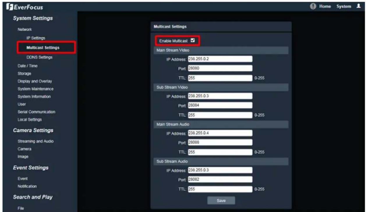
text_image
EverFocus System Settings Network IP Settings Multicast Settings DDNS Settings Date / Time Storage Display and Overlay System Maintenance System Information User Serial Communication Local Settings Camera Settings Streaming and Audio Camera Image Event Settings Event Notification Search and Play File Multicast Settings Enable Multicast ✓ Main Stream Video IP Address: 238.255.0.2 Port: 28080 TTL: 255 0-255 Sub Stream Video IP Address: 238.255.0.3 Port: 28084 TTL: 255 0-255 Main Stream Audio IP Address: 238.255.0.4 Port: 28088 TTL: 255 0-255 Sub Stream Audio IP Address: 238.255.0.3 Port: 28082 TTL: 255 0-255 Save- Go to the setng page of the router / switch to enable the Mulcast funcon.
Here we use a D-Link DIR655 router and EverFocus 24-port switch for example.

text_image
D-Link QIR-455 SETUP ADVANCED TOOLS STATUS SUPPORT VIRTUAL SERVER ADADVANCED NETWORK PORT FORWARDING APPLICATION RATES UPnP Universal Plug and Play (UPnP) supports peer-to-peer Plug and Play functionality for network devices. Enable UPnP : WAR PING If you enable this feature, the WAR port of your router will respond to ping requests from the Internet that are sent to the WAR IP Address. Enable WAR Ping Respond : WAR Ping Inbound Filter : Allow All Details : Allow All WAR PORT SPEED WAR Port Speed : Auto 10/100/100Mbps MULTICAST STREAMS Enable Multicast Streams : HELP... UPP helps other UPnP LAN links and responded with the router. Let me the UPnP option enabled as long as the LAN has other UPnP applications. Fix added security, & a recommended that you double the WAR Ping respond option. Ping is often used by mode bus Internet users to locate active networks or PCA. The WAR speed is usually detected automatically. If you are having problems connecting to the VASK, by adjusting the speed manuals. If you are having trouble receiving multicast streams from the Internet, make sure the multicast streams option is enabled. Help...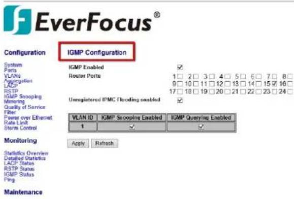
text_image
EverFocus® Configuration IGMP Configuration System IGMP Enabled Ports VLANs Router Ports 1 2 3 4 5 6 7 8 Aggregation 9 10 11 12 13 14 15 16 LACP RSTP 17 18 19 20 21 22 23 24 IGMP Snooping Mining Unregistered IPMG Flooding enabled Quality of Service Filter Power over Ethernet Rate Limit Storm Control VLAN ID IGMIP Snooping Enabled IGMIP Querying Enabled 1 ✓ ✓ Monitoring Apply Refresh Statistics Overview Detailed Statistics LACP Status RSTP Status IGMP Status Ping Maintenance- The Mulcast funcon setup is now complete.
C. RTSP URL Syntax
Following is the RTSP URL syntax of EverFocus' IP cameras.
rtsp://[device-ip-address]/ch1_[main]
* [device-ip-address] is the IP address of the IP camera
* [main] is for Main Stream; [sub] is for Sub Stream
For example, if the IP address of the IP camera is 192.168.37.55, the RTSP URL (main stream / sub stream) of this IP camera will be:
Main Stream:
rtsp://192.168.37.55/ch1_main
Sub Stream:
rtsp://192.168.37.55/ch1_sub
Note: If you have diculty getting the live view image, please reduce the number of clients accessing the IP camera.
D. Seng up Port Forwarding Funcon
IP Camera port forwarding can be used when users need to access a certain IP camera from outside of the local network where the IP camera is connected to.
To enable the IP camera port forwarding funcon, you have to conjure the port forwarding sengs both on the IP camera and the router (UPnP-enabled). Please follow the steps below:

flowchart
graph LR
    PC["PC"] --> RouterSwitch["Router Switch"]
    RouterSwitch --> IPCamera["IP Camera"]
    IPCamera --> Notebook["Notebook"]
    RouterSwitch --> RouterSwitch
- Go to System > System Sengs > Network > IP Sengs.

text_image
EverFocus System Settings Network IP Settings Multicast Settings DDNS Settings Date / Time Storage Display and Overlay System Maintenance System Information User Serial Communication Local Settings Camera Settings Streaming and Audio Camera Image IP Settings IPV4 Static IP DHCP HTTP Port: 80 HTTPS Port: 443 RTSP Port: 554 RTMP Port: 1935 Enable UPnP: Device Port: 5050 Enable PPPoE: User Name: Password: Confirm PWD: PPPoE IP: 100.100.100.100 Savea. Set up a stac IP for the IP camera. Type in the subnet mask, gateway and the DNS if provided by the Internet Service Provider.
b. Enter the port numbers and check the Enable UPnP box to enable the port forwarding funcon. Click the Save buon.
The default ports of all EverFocus' IP cameras are as below. You can change the port numbers if necessary. Be sure the port numbers setup on the router match the ones setup here.
HTTP: 80
HTTPS: 443
RTSP: 554
- Set up the port forwarding settings on the router. Here we use D-Link's router for example.
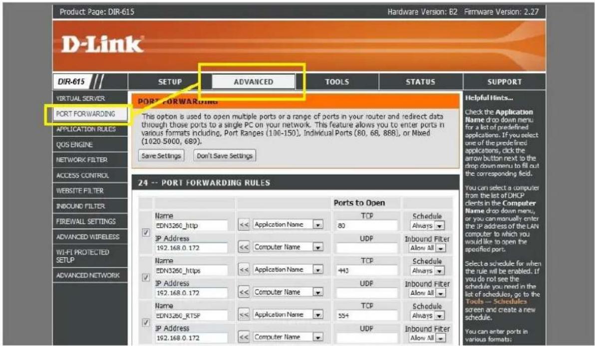
text_image
Product: Page: DIR-615 Hardware Version: B2 Firmware Version: 2.27 D-Link® DIR-615 SETUP ADVANCED TOOLS STATUS SUPPORT VIRTUAL SERVER PORT FORWARDING This option is used to open multiple ports or a range of ports in your router and redirect data through those ports to a single PC on your network. This feature allows you to enter ports in various formats including, Port Ranges (100-150), Individual Ports (80, 68, 888), or Mixed (1020-5000, 689). Save Settings Don't Save Settings PORT FORWARDING 24 -- PORT FORWARDING RULES Name EDN3260_http Application Name TCP Schedule 80 Always IP Address 192.168.0.172 Computer Name UDP Inbound Filter 443 Allow All Name EDN3260_https Application Name TCP Schedule 192.168.0.172 Computer Name UDP Inbound Filter 443 Allow All IP Address 192.168.0.172 Application Name TCP Schedule 554 Always IP Address 192.168.0.172 Computer Name UDP Inbound Filter 443 Allow All Helpful Hints... Check the Application Name drop down menu for a list of predefined applications. If you select one of the predefined applications, click the arrow button next to the drop down menu to fill out the corresponding field. You can select a computer from the list of DHCP clients in the Computer Name drop down menu, or you can manually enter the IP address of the LAN computer to which you would like to open the specified port. Select a schedule for when the rule will be enabled. If you do not see the schedule you need in the list of schedules, go to the Tools -- Schedules screen and create a new schedule. You can enter ports in various formats:Please be noted that each router may look dierent in some ways, however, the concept of the port forwarding seng is the same. For more details, please consult the manual of your router.
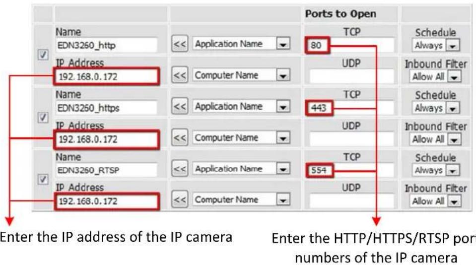
text_image
Ports to Open Name EDN3260_http << Application Name 80 TCP Schedule Always IP Address 192.168.0.172 << Computer Name UDP Inbound Filter Allow All Name EDN3260_https << Application Name 443 TCP Schedule Always IP Address 192.168.0.172 << Computer Name UDP Inbound Filter Allow All Name EDN3260_RTSP << Application Name 554 TCP Schedule Always IP Address 192.168.0.172 << Computer Name UDP Inbound Filter Allow All Enter the IP address of the IP camera Enter the HTTP/HTTPS/RTSP port numbers of the IP camera- Open a browser and type in the IP address of the router, now you are able to access the IP camera from the Internet.
E. Seng up DDNS Funcon
If you set up your IP Camera with DHCP network, the IP address of your IP Camera may change at dierent mes for dierent reasons, particularly aer a power failure. The changing IP address of the IP Camera may cause you dicules accessing the IP Camera. To solve this problem, you can set up the DDNS funcon to your IP Camera, and access your IP Camera with a xed host name whenever the IP address of your IP Camera changes.
DDNS (Dynamic Domain Name System) is a service used to map a domain name to the dynamic IP address of a network device. It assigns a domain name (URL) to the IP Camera, so that the user does not need to go through the trouble of checking if the IP address assigned by DHCP Server has changed. Once the IP is changed, the IP Camera will automatically update the informaon to the DDNS to ensure it is always available for remote access.
To set up DDNS for your IP Camera, you have to 1) enable the DMZ or Port Forwarding funcon of your router 2) conjure the network seng of your IP Camera 3) conjure the DDNS seng of your IP Camera. Please follow the steps below.
To enable the DDNS funcon:
- In order to access the IP camera from outside of the local network, enable either the Port Forwarding or DMZ funcon of your router. Please refer to the manual of your router for more details.
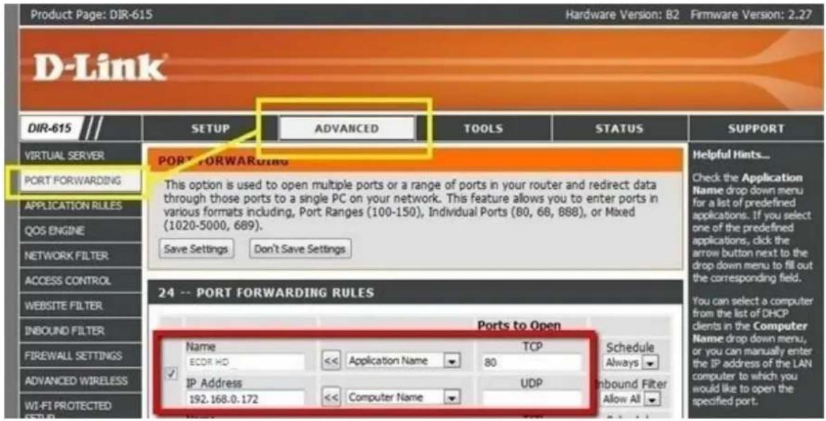
text_image
Product Page: DIR-615 Hardware Version: B2 Firmware Version: 2.27 DIR-615 SETUP ADVANCED TOOLS STATUS SUPPORT VIRTUAL SERVER PORT FORWARDING This option is used to open multiple ports or a range of ports in your router and redirect data through those ports to a single PC on your network. This feature allows you to enter ports in various formats including, Port Ranges (100-150), Individual Ports (80, 68, 888), or Mixed (1020-5000, 689). Save Settings Don't Save Settings Helpful Hints... Check the Application Name drop down menu for a list of predefined applications. If you select one of the predefined applications, click the arrow button next to the drop down menu to fill out the corresponding field. ACCESS CONTROL WEBSITE FILTER INBOUND FILTER FIREWALL SETTINGS ADVANCED WIRELESS WI-FI PROTECTED 24 -- PORT FORWARDING RULES Ports to Open Name TCP Schedule ECOR HD << Application Name 80 Always IP Address UDP Inbound Filter Allow All 192.168.0.172 << Computer NameNote: If you enable the Port Forwarding of your router, the Enable UPnP Port Forwarding funcon must be enabled on the IP camera (see Port Setngs eld in the Step 2 image).

text_image
DIR-86SL VIRTUAL SERVER PORT FORWARDING APPLICATION RULES QOS ENGINE NETWORK FILTER ACCESS CONTROL WEBSITE FILTER INBOUND FILTER FIREWALL SETTINGS ROUTING ADVANCED WIRELESS WI-FI PROTECTED SETUP ADVANCED NETWORK DLNA SETTINGS ITUNES SERVER GUEST ZONE IPV6 FIREWALL IPV6 ROUTING FIREWALL & DMZ SETTINGS DMZ means "Demilitarized Zone". DMZ allows computers behind the router firewall to be accessible to Internet traffic. Typically, your DMZ would contain Web servers, FTP servers and others. Save Settings Don't Save Settings FIREWALL SETTINGS Enable SPI : □ ANTI-SPOOF CHECKING Enable anti-spoof checking : □ DMZ HOST The DMZ (Demilitarized Zone) option lets you set a single computer on your network outside of the router. If you have a computer that cannot run Internet applications successfully from behind the router, then you can place the computer into the DMZ for unrestricted Internet access. Note: Putting a computer in the DMZ may expose that computer to a variety of security risks. Use of this option is only recommended as a last resort. Enable DMZ : ✓ DMZ IP Address : 192.168.0.119 × << Computer Name ✓- On the Network Setng page (Seng > System Sengs > Network > IP Sengs), congure the IP Sengs, keep the default Port Sengs and then click the Save buon.

text_image
EverFocus System Settings Network IP Settings Multicast Settings DDNS Settings Date / Time Storage Display and Overlay System Maintenance System Information User Serial Communication Local Settings Camera Settings Streaming and Audio Camera Image IP Settings IPV4 Static IP DHCP HTTP Port: 80 HTTPS Port: 443 RTSP Port: 554 RTMP Port: 1935 Enable UPnP: Device Port: 5050 Enable PPPoE: User Name: Password: Confirm PWD: PPPoE IP: 100.100.100.100 Save- If Stac IP is selected: Enter the IP address, subnet mask, default gateway and the DNS Server. Please consult with your ISP service provider for the informaon of subnet mask, default gateway and the DNS Server.
- If DHCP is selected: The IP address, subnet mask, default gateway and the DNS Server will be assigned automacally by DHCP server.
-
If Enable PPPoE is selected: Enter the User Name (e.g. xxxx@hinet.net) and Password provided by your ISP service provider.
-
In the DDNS Sengs eld (Setng > System Sengs > Network > DDNS Sengs), register a free host name from EverFocus DDNS and then click the Save buon.

text_image
EverFocus System Settings Network IP Settings Multicast Settings DDNS Settings Date/Time Storage Display and Overlay System Maintenance System Information User Serial Communication Local Settings Camera Settings Streaming and Audio Camera DDNS Settings Enable DDNS: Server Type: EverFocusDDNS Server Name: www.everfocusddns.com Port: 80 User Name: Password: Confirm pwd: Domain: Savea. Check Enable DDNS to enable the DDNS funcon.
b. Select www.everfocusddns.com and enter a desired host name in the Domain eld.
Note: The host name should not include a space, or a dot (period) or any special characters particularly _\~ ! @ # \$ % ^ & * ( ) + < > "; : . ,
c. Click Save.
- The DDNS setup is now complete. Open a browser and enter the domain name (hp://[host name].everfocusddns.com) in the address eld. The Web interface of the device should be displayed. For example, if you've obtained the host name "HQtest" from EverFocus DDNS server, enter hp://HQtest.everfocusddns.com in the address eld of the browser.

text_image
http://HQtest.everfocusddns.com EverFocus Home Streaming Camera Lens CTRL SystemEverFocus Electronics Corp.
EverFocus Taiwan:
12F-1, No.79, Sec. 1, Shin-Tai Wu Road,
Hsi-Chih, New Taipei City, Taiwan
TEL: +886 2 2698 2334
FAX: +886 2 2698 3943
www.everfocus.com.tw
markeng@everfocus.com.tw
EverFocus China - Beijing:
Room 609, Technology Trade Building, Shangdi Informaon Industry Base,
Haidian District, Beijing 100085, China
TEL: +86 10 6297 3336\~39
FAX: +86 10 6297 1423
www.everfocus.com.cn
markeng@everfocus.com.cn
EverFocus USA - California:
1801 Highland Avenue, Unit A, Duarte, CA 91010, USA
TEL: +1 626 844 8888
FAX: +1 626 844 8838
www.everfocus.com
sales@everfocus.com
EverFocus Europe - Germany:
Albert-Einstein-Strasse 1, D-46446
Emmerich, Germany
TEL: +49 2822 93940
FAX: +49 2822 939495
www.everfocus.de
sales@everfocus.de
EverFocus China - Shenzhen:
4F, No. 2, D4 Building, Wan Yelong
Industrial Park, Tangtou Road, Shiyan,
Baoan, Shenzhen, Guangdong 518101, China
TEL: +86 755 2765 1313
FAX: +86 755 2765 0337
www.everfocus.com.cn
markeng@everfocus.com.cn
EverFocus Japan:
3F, Kuramochi, Building II
2-2-3 Koto-Bashi, Sumida-Ku,
Tokyo, 130-0022, Japan
TEL: +81 3 5625 8188
FAX: +81 3 5625 8189
www.everfocus.co.jp
info@everfocus.co.jp

Your EverFocus product is designed and manufactured with high quality materials and components which can be recycled and reused.
This symbol means that electrical and electronic equipment, at their end-of-life, should be disposed of separately from your household waste. Please, dispose of this equipment at your local community waste collection/recycling centre.
In the European Union there are separate collection systems for used electrical and electronic product. Please, help us to conserve the environment we live in!