
VS-2480DVD - Musical instrument ROLAND - Free user manual and instructions
Find the device manual for free VS-2480DVD ROLAND in PDF.

| Product Type | Digital Studio Workstation |
| Model | VS-2480DVD |
| Brand | Roland |
| Recording Medium | Internal hard disk (IDE), optional CD-R/RW, Zip drive |
| Number of Tracks | 24 (16+8) with optional V-Track expansion up to 64 virtual tracks |
| Audio Resolution | 24-bit, 44.1/48 kHz |
| Mixer Channels | 24 input channels, 24 track channels, 8 aux return, 8 FX return |
| Built-in Effects | 2 multi-effects processors (expandable to 4 with VS8F-2), algorithm-based (reverb, delay, EQ, etc.) |
| Analog Inputs | 8 XLR (with phantom power), 16 TRS (1/4"), 1 Hi-Z guitar input |
| Analog Outputs | Main stereo out (XLR and TRS), 8 direct outs (TRS), monitor out, 2 headphone jacks |
| Digital I/O | Coaxial S/PDIF, optical (ADAT), R-BUS, word clock |
| MIDI | In/Out/Thru, supports MIDI control surface (V.Fader), MTC/SMPTE sync |
| Display | 320x240 backlit LCD, external VGA monitor support |
| Storage Media | Internal IDE hard drive (user-installable), external SCSI Zip, CD-RW |
| Power Supply | AC 120V or 240V, 50/60 Hz; consumption approx. 60W |
| Dimensions (Approx.) | 560 mm (W) x 560 mm (D) x 200 mm (H) / 22" x 22" x 7.9" |
| Weight (Approx.) | 18 kg / 40 lbs |
| Maintenance | Clean with a soft dry cloth; avoid benzine, thinners, or alcohol |
| Safety | Always observe warnings: use grounded outlet, avoid water/moisture, no user-serviceable parts inside |
| Repairability | Refer servicing to qualified Roland service centers; replace internal lithium battery (CR2032) per manual |
Frequently Asked Questions - VS-2480DVD ROLAND
User questions about VS-2480DVD ROLAND
0 question about this device. Answer the ones you know or ask your own.
Ask a new question about this device
Download the instructions for your Musical instrument in PDF format for free! Find your manual VS-2480DVD - ROLAND and take your electronic device back in hand. On this page are published all the documents necessary for the use of your device. VS-2480DVD by ROLAND.
USER MANUAL VS-2480DVD ROLAND
Before using this unit, carefully read the sections entitled: "ALWAYS OBSERVE THE FOLLOWING" (Owner's Manual p. 2), "USING THE UNIT SAFELY" (Owner's Manual p. 2), and "IMPORTANT NOTES" (Owner's Manual p. 4). These sections provide important information concerning the proper operation of the unit. Additionally, in order to feel assured that you have gained a good grasp of every feature provided by your new unit, the User Guide, Owner's Manual, and Appendices should be read in their entirety. These manuals should be saved and kept on hand as a convenient reference.
Copyright© 2001 ROLAND CORPORATION
All rights reserved. No part of this publication may be reproduced in any form without written permission of ROLAND CORPORATION.
Roland US Web Site: www.rolandus.com

ATTENTION

RISQUE DE CHOC ELECTRIQUE NE PAS OUVRIR

CAUTION: TO REDUCE THE RISK OF ELECTRIC SHOCK, DO NOT REMOVE COVER (OR BACK). NO USER-SERVICEABLE PARTS INSIDE. REFER SERVICING TO QUALIFIED SERVICE PERSONNEL.

The lightning flash with arrowhead symbol, within an equilateral triangle, is intended to alert the user to the presence of uninsulated “dangerous voltage” within the product’s enclosure that may be of sufficient magnitude to constitute a risk of electric shock to persons.

The exclamation point within an equilateral triangle is intended to alert the user to the presence of important operating and maintenance (servicing) instructions in the literature accompanying the product.
INSTRUCTIONS PERTAINING TO A RISK OF FIRE, ELECTRIC SHOCK, OR INJURY TO PERSONS.
IMPORTANT SAFETY INSTRUCTIONS SAVE THESE INSTRUCTIONS
WARNING - When using electric products, basic precautions should always be followed, including the following:
- Read these instructions.
- Keep these instructions.
- Heed all warnings.
- Follow all instructions.
- Do not use this apparatus near water.
- Clean only with a dry cloth.
- Do not block any of the ventilation openings. Install in accordance with the manufacturers instructions.
- Do not install near any heat sources such as radiators, heat registers, stoves, or other apparatus (including amplifiers) that produce heat.
-
Do not defeat the safety purpose of the polarized or grounding-type plug. A polarized plug has two blades with one wider than the other. A grounding type plug has two blades and a third grounding prong. The wide blade or the third prong are provided for your safety. If the provided plug does not fit into your outlet, consult an electrician for replacement of the obsolete outlet.
-
Protect the power cord from being walked on or pinched particularly at plugs, convenience receptacles, and the point where they exit from the apparatus.
- Only use attachments/accessories specified by the manufacturer.
- Unplug this apparatus during lightning storms or when unused for long periods of time.
- Refer all servicing to qualified service personnel. Servicing is required when the apparatus has been damaged in any way, such as power-supply cord or plug is damaged, liquid has been spilled or objects have fallen into the apparatus, the apparatus has been exposed to rain or moisture, does not operate normally, or has been dropped.
For the U.K.
WARNING: THIS APPARATUS MUST BE EARTHED
IMPORTANT: THE WIRES IN THIS MAINS LEAD ARE COLOURED IN ACCORDANCE WITH THE FOLLOWING CODE. GREEN-AND-YELLOW: EARTH, BLUE: NEUTRAL, BROWN: LIVE
As the colours of the wires in the mains lead of this apparatus may not correspond with the coloured markings identifying the terminals in your plug, proceed as follows:
The wire which is coloured GREEN-AND-YELLOW must be connected to the terminal in the plug which is marked by the letter E or by the safety earth symbol ⏻ or coloured GREEN or GREEN-AND-YELLOW.
The wire which is coloured BLUE must be connected to the terminal which is marked with the letter N or coloured BLACK. The wire which is coloured BROWN must be connected to the terminal which is marked with the letter L or coloured RED.
CAUTION: Danger of explosion if battery is incorrectly replaced. Replace only with same or equivalent type.
USING THE UNIT SAFELY
INSTRUCTIONS FOR THE PREVENTION OF FIRE, ELECTRIC SHOCK, OR INJURY TO PERSONS
About ⚠️ WARNING and ⚠️ CAUTION Notices
 | Used for instructions intended to alert the user to the risk of death or severe injury should the unit be used improperly. |
 | Used for instructions intended to alert the user to the risk of injury or material damage should the unit be used improperly.* Material damage refers to damage or other adverse effects caused with respect to the home and all its furnishings, as well to domestic animals or pets. |
About the Symbols
| The △ symbol alerts the user to important instructions or warnings. The specific meaning of the symbol is determined by the design contained within the triangle. In the case of the symbol at left, it is used for general cautions, warnings, or alerts to danger. | |
| The ⬇ symbol alerts the user to items that must never be carried out (are forbidden). The specific thing that must not be done is indicated by the design contained within the circle. In the case of the symbol at left, it means that the unit must never be disassembled. | |
| The symbol alerts the user to things that must be carried out. The specific thing that must be done is indicated by the design contained within the circle. In the case of the symbol at left, it means that the power-cord plug must be unplugged from the outlet. |
ALWAYS OBSERVE THE FOLLOWING
WARNING
- Before using this unit, make sure to read the instructions below, and the Owner's Manual.

- Connect mains plug of this model to a mains socket outlet with a protective earthing connection.

- Do not open or perform any internal modifications on the unit. (The only exception would be where this manual provides specific instructions which should be followed in order to put in place user-installable options; see User Guide p. 12.)

- Do not attempt to repair the unit, or replace parts within it (except when this manual provides specific instructions directing you to do so). Refer all servicing to your retailer, the nearest Roland Service Center, or an authorized Roland distributor, as listed on the "Information" page.

- Never use or store the unit in places that are:
- Subject to temperature extremes (e.g., direct sunlight in an enclosed vehicle, near a heating duct, on top of heat-generating equipment); or are

- Damp (e.g., baths, washrooms, on wet floors); or are

- Humid; or are
- Exposed to rain; or are
- Dusty; or are
- Subject to high levels of vibration.
• Make sure you always have the unit placed so it is level and sure to remain stable. Never place it on stands that could wobble, or on inclined surfaces.

- The unit should be connected to a power supply only of the type described in the operating instructions, or as marked on the rear side of unit.

- Use only the attached power-supply cord. Also, the supplied power cord must not be used with any other device.

- Do not excessively twist or bend the power cord, nor place heavy objects on it. Doing so can damage the cord, producing severed elements and short circuits. Damaged cords are fire and shock hazards!

- This unit, either alone or in combination with an amplifier and headphones or speakers, may be capable of producing sound levels that could cause permanent hearing loss. Do not operate for a long period of time at a high volume level, or at a level that is uncomfortable. If you experience any hearing loss or ringing in the ears, you should immediately stop using the unit, and consult an audiologist.

- Do not allow any objects (e.g., flammable material, coins, pins); or liquids of any kind (water, soft drinks, etc.) to penetrate the unit.


WARNING
- Immediately turn the power off, remove the power cord from the outlet, and request servicing by your retailer, the nearest Roland Service Center, or an authorized Roland distributor, as listed on the "Information" page when:

- The power-supply cord, or the plug has been damaged; or
• If smoke or unusual odor occurs - Objects have fallen into, or liquid has been spilled onto the unit; or
- The unit has been exposed to rain (or otherwise has become wet); or
- The unit does not appear to operate normally or exhibits a marked change in performance.
- In households with small children, an adult should provide supervision until the child is capable of following all the rules essential for the safe operation of the unit.

- Protect the unit from strong impact. (Do not drop it!)

- Do not force the unit's power-supply cord to share an outlet with an unreasonable number of other devices. Be especially careful when using extension cords—the total power used by all devices you have connected to the extension cord's outlet must never exceed the power rating (watts/amperes) for the extension cord. Excessive loads can cause the insulation on the cord to heat up and eventually melt through.

- Before using the unit in a foreign country, consult with your retailer, the nearest Roland Service Center, or an authorized Roland distributor, as listed on the "Information" page.

- Keep lithium batteries out of reach of small children. If a child has accidentally swallowed a battery, see a doctor immediately.

• Lithium batteries must never be recharged, heated, taken apart, or thrown into a fire or water.


• Always turn the unit off and unplug the power cord before attempting installation of the circuit board (model no. VS8F-2; p. 379).

WARNING
- DO NOT play a CD-ROM disc on a conventional audio CD player. The resulting sound may be of a level that could cause permanent hearing loss. Damage to speakers or other system components may result.

- Do not put anything that contains water (e.g., flower vases) on this unit. Also, avoid the use of insecticides, perfumes, alcohol, nail polish, spray cans, etc., near the unit. Swiftly wipe away any liquid that spills on the unit using a dry, soft cloth.


CAUTION
- The unit should be located so that its location or position does not interfere with its proper ventilation.

• Always grasp only the plug on the power-supply cord when plugging into, or unplugging from, an outlet or this unit.

- At regular intervals, you should unplug the power plug and clean it by using a dry cloth to wipe all dust and other accumulations away from its prongs. Also, disconnect the power plug from the power outlet whenever the unit is to remain unused for an extended period of time. Any accumulation of dust between the power plug and the power outlet can result in poor insulation and lead to fire.

- Try to prevent cords and cables from becoming entangled. Also, all cords and cables should be placed so they are out of the reach of children.

- Never climb on top of, nor place heavy objects on the unit.

- Never handle the power cord or its plugs with wet hands when plugging into, or unplugging from, an outlet or this unit.

- Before moving the unit, disconnect the power plug from the outlet, and pull out all cords from external devices.

- Before cleaning the unit, turn off the power and unplug the power cord from the outlet (p. 80).

- Whenever you suspect the possibility of lightning in your area, pull the plug on the power cord out of the outlet.

- Use only the specified type (model no. CR2032) of lithium battery (p. 382). Be sure to insert it as directed (to ensure correct polarity).

• Used lithium batteries must be disposed of in compliance with whatever regulations for their safe disposal that may be observed in the region in which you live.

- Install only the specified circuit board(s) (model no. VS8F-2). Remove only the specified screws (p. 379).


CAUTION
- Keep any optical connector caps or screws you may remove and the included optical connector caps or screws in a safe place out of children's reach, so there is no chance of them being swallowed accidentally.

- Always turn the phantom power off when connecting any device other than condenser microphones that require phantom power. You risk causing damage if you mistakenly supply phantom power to dynamic microphones, audio playback devices, or other devices that don't require such power. Be sure to check the specifications of any microphone you intend to use by referring to the manual that came with it.

(This instrument's phantom power: 48 V DC, 14 mA Max)
Important Notes
In addition to the items listed under "IMPORTANT SAFETY INSTRUCTIONS" and "USING THE UNIT SAFELY" on pages (p. 2) and (p. 3), please read and observe the following:
Power Supply
- Do not connect this unit to same electrical outlet that is being used by an electrical appliance that is controlled by an inverter (such as a refrigerator, washing machine, microwave oven, or air conditioner), or that contains a motor. Depending on the way in which the electrical appliance is used, power supply noise may cause this unit to malfunction or may produce audible noise. If it is not practical to use a separate electrical outlet, connect a power supply noise filter between this unit and the electrical outlet.
- Before connecting this unit to other devices, turn off the power to all units. This will help prevent malfunctions and/or damage to speakers or other devices.
- Although the LCD and LEDs are switched off when the POWER switch is switched off, this does not mean that the unit has been completely disconnected from the source of power. If you need to turn off the power completely, first turn off the POWER switch, then unplug the power cord from the power outlet. For this reason, the outlet into which you choose to connect the power cord's plug should be one that is within easy reach and readily accessible.
Placement
- This device may interfere with radio and television reception. Do not use this device in the vicinity of such receivers.
- Noise may be produced if wireless communications devices, such as cell phones, are operated in the vicinity of this unit. Such noise could occur when receiving or initiating a call, or while conversing. Should you experience such problems, you should relocate such wireless devices so they are at a greater distance from this unit, or switch them off.
- Do not expose the unit to direct sunlight, place it near devices that radiate heat, leave it inside an enclosed vehicle, or otherwise subject it to temperature extremes. Excessive heat can deform or discolor the unit.
- When moved from one location to another where the temperature and/or humidity is very different, water droplets (condensation) may form inside the unit. Damage or malfunction may result if you attempt to use the unit in this condition. Therefore, before using the unit, you must allow it to stand for several hours, until the condensation has completely evaporated.
Maintenance
- For everyday cleaning wipe the unit with a soft, dry cloth or one that has been slightly dampened with water. To remove stubborn dirt, use a cloth impregnated with a mild, non-abrasive detergent. Afterwards, be sure to wipe the unit thoroughly with a soft, dry cloth.
- Never use benzine, thinners, alcohol or solvents of any kind, to avoid the possibility of discoloration and/or deformation.
Repairs and Data
- Please be aware that all data contained in the unit's memory may be lost when the unit is sent for repairs. Important data should always be backed up on a storage device (e.g., CD-R/RW disc or Zip disk), or written down on paper (when possible). During repairs, due care is taken to avoid the loss of data. However, in certain cases (such as when circuitry related to memory itself is out of order), we regret that it may not be possible to restore the data, and Roland assumes no liability concerning such loss of data.
Memory Backup
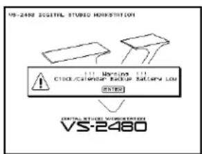
- This unit contains a battery which powers the unit's memory circuits while the main power is off. When this battery becomes weak, the message shown below will appear in the display. Once you see this message, have the battery replaced with a fresh one as soon as possible to avoid the loss of all data in memory. To have the battery replaced, consult with your retailer, the nearest Roland Service Center, or an authorized Roland distributor, as listed on the "Information" page.
Additional Precautions
- Please be aware that the contents of memory can be irretrievably lost as a result of a malfunction, or the improper operation of the unit. To protect yourself against the risk of loosing important data, we recommend that you periodically save a backup copy of important data you have stored in the unit's memory on a storage device (e.g., CD-R/RW disc or Zip disk).
- Unfortunately, it may be impossible to restore the contents of data that was stored on a storage device (e.g., CD-R/RW disc or Zip disk) once it has been lost. Roland Corporation assumes no liability concerning such loss of data.
- Use a reasonable amount of care when using the unit's buttons, sliders, or other controls; and when using its jacks and connectors. Rough handling can lead to malfunctions.
- Never strike or apply strong pressure to the display.
- When connecting / disconnecting all cables, grasp the connector itself—never pull on the cable. This way you will avoid causing shorts, or damage to the cable's internal elements.
- A small amount of heat will radiate from the unit during normal operation.
- To avoid disturbing your neighbors, try to keep the unit's volume at reasonable levels. You may prefer to use headphones, so you do not need to be concerned about those around you (especially when it is late at night).
- When you need to transport the unit, package it in the box (including padding) that it came in, if possible. Otherwise, you will need to use equivalent packaging materials.
- Use a cable from Roland to make the connection. If using some other make of connection cable, please note the following precautions.
- Some connection cables contain resistors. Do not use cables that incorporate resistors for connecting to this unit. The use of such cables can cause the sound level to be extremely low, or impossible to hear. For information on cable specifications, contact the manufacturer of the cable.
Handling Zip Disks
- Zip disks contain a plastic disk with a thin coating of magnetic storage medium. Microscopic precision is required to enable storage of large amounts of data on such a small surface area. To preserve their integrity, please observe the following when handling Zip disks:
- Never touch the magnetic medium inside the disk.
-
Do not use or store Zip disks in dirty or dusty areas.
-
Do not subject Zip disks to temperature extremes (e.g., direct sunlight in an enclosed vehicle). Recommended temperature range: -22 to 51°C (-7.6 to 123.8°F).
-
Do not expose Zip disks to strong magnetic fields, such as those generated by loudspeakers.
-
The identification label should be firmly affixed to the disk. Should the label come loose while the disk is in the drive, it may be difficult to remove the disk.
- Store all disks in a safe place to avoid damaging them, and to protect them from dust, dirt, and other hazards. By using a dirty or dust-ridden disk, you risk damaging the disk, as well as causing the disk drive to malfunction.
Handling CD-ROMs
- Avoid touching or scratching the shiny underside (encoded surface) of the disc. Damaged or dirty CD-ROM discs may not be read properly. Keep your discs clean using a commercially available CD cleaner.
Handling Hard Disks
Important Performance and Image Data
- Once a hard disk fails to function normally, all data that has been stored on it could be destroyed. All hard disks eventually wear out. We recommend that you consider the hard disk not as a permanent storage site, but as a place to store data temporarily. We also recommend that you back up important performance and image data that cannot be recorded again onto the external media that is supported by your device. For instructions on how to make such backups, refer to the owner's manual for your device. Note that Roland assumes no liability whatsoever, including monetary compensation, for the loss of any recorded content in the event of the malfunction of, or physical damage to the hard disk, or for any direct or incidental damages resulting from the loss of such data.
Precautions Regarding Setup and Use
- Certain hard disk setup procedures and usage conditions may result in the corruption of recorded data, malfunctioning, or physical damage to the disk, so be sure to observe the following precautions.
- Do not subject the hard disk to vibration or shock, especially while the unit is in operation.
- Do not set up the unit in any location where it may be affected by vibration from external sources, or on any surface that is not stable and level.
-
If the device includes a cooling fan, ensure that the fan and the side panel air vents remain unobstructed.
-
Do not leave the unit in any environment subject to temperature extremes; for example, in a closed automobile in summer or outdoors during winter.
- Do not use the unit in conditions of high temperature and humidity or in any location subject to rapid temperature changes.
- Do not unplug the power cord or switch off any circuit breakers in the circuit to which the unit is connected while the power is turned on.
- Do not move the unit while the power is turned on or immediately after turning off the power. When transporting the unit, first turn off the power and confirm that the display screen has gone off, disconnect the power plug, then wait at least two minutes before moving the device.
Emergency Procedures
* The following procedures are to be used as emergency measures only, and are not recommended for normal operation.
- If the device fails to respond to operational commands or does not complete operations, turn off the power. If the power does not shut off following normal shutdown procedures, disconnect the power plug.
If the unit does not operate normally when the power is turned on again, it may mean that the hard disk has been damaged. In such instances, consult your dealer or the nearest Roland Service Center. Note, however, that it may not be possible to recover any data from the hard disk once it has been lost.
If your device features drive check capabilities, use the drive check function to regularly confirm that there are no problems, even when the device is operating normally. For more detailed information on the shutdown and drive check procedures, refer to the Owner's Manual.
Copyright
- Unauthorized recording, distribution, sale, lending, public performance, broadcasting, or the like, in whole or in part, of a work (musical composition, video, broadcast, public performance, or the like) whose copyright is held by a third party is prohibited by law.
- When exchanging audio signals through a digital connection with an external instrument, this unit can perform recording without being subjected to some of the restrictions of the Serial Copy Management System (SCMS). This is because the unit is intended solely for musical production, and is designed not to be subject to restrictions as long as it is used to record works (such as your own compositions) that do not infringe on the copyrights of others. (SCMS is a feature that prohibits second-generation and later copying through a digital connection. It is built into MD recorders and other consumer digital-audio equipment as a copyright-protection feature.)
- Do not use this unit for purposes that could infringe on a copyright held by a third party. We assume no responsibility whatsoever with regard to any infringements of third-party copyrights arising through your use of this unit.
Table of Contents
Step-by-Step Instruction Finder 20
1—Welcome 27
About this Manual 27
How the VS-2480 Owner's Manual is Organized 27
Names 28
Note, Tip, Glossary and Warning Icons 28
Other Documents in the VS-2480 Box 29
Getting More Help 29
The Roland US Web site 29
The Roland US Faxback System 29
Roland US Product Support 29
2—Getting Around 31
The Top Panel of the VS-2480 31
Analog Input Jacks 31
Monitor/Display Controls 32
Channel Strips 33
Display Area 36
TRACK EDIT Area 37
EZ ROUTING, AUTOMIX, CD-RW/MASTERING and MENU Buttons 39
General Controls 41
SCRUB, PREVIEW and Transport Buttons 42
LOCATOR/MARKER/SCENE Area 44
The Rear Panel of the VS-2480 46
3—Introduction to the VS-2480 51
What's Inside the VS-2480? 51
Input Jacks and Connectors 51
The Mixing Console 52
The Internal Effects 54
The Hard Disk Recorder 55
Output Jacks and Connectors 55
Signal Flow 56
Projects 56
Busses in the VS-2480 57
What's a Bus? 57
Achieving Perfect Levels 58
What's "Clipping?" 58
How Do I Get Good Levels? 58
The Importance of Backing Up 59
4—Setting Up and Basic Operations 61
Things You'll Need 61
Power 61
A Way to Listen to the VS-2480 61
Getting Ready 61
Powering Up 63
What Happens During the VS-2480's Power-Up 63
Configuring the VS-2480 64
Setting Up the VGA Monitor, Mouse and Keyboard 64
Setting the VS-2480's Clock 65
A Few Fundamental Concepts 65
Selection 65
Switches 66
Parameters and Values 66
Tools You'll Use All the Time 66
The Cursor/ZOOM Buttons 66
The F Buttons 66
Pages 67
The TIME/VALUE Dial 67
The ENTER/YES and EXIT/NO Buttons 67
The SHIFT Button 68
Using a Mouse 68
Using an ASCII Keyboard 69
Using the VGA Info Display 70
UNDO and REDO 72
Naming 73
Entering Numbers with the Numeric Keypad 74
If You're Using DS-90A or DS-50A Monitors 75
Setting Up for Roland's DS-90A and DS-50A Digital Monitors 75
Adjusting Your Listening Level 75
Playing the Factory Demos 76
"What You Don't Know" 76
"Don't Stop" 80
Turning Off the VS-2480 80
Turning Off the VS-2480 80
5—Understanding Effects 81
Harnessing the VS-2480's Effects 81
Dry and Wet 81
Effect Routings 81
Insert Effects 82
Loop Effects 82
Master Effects 83
External Effects 83
Getting the Most From Your Effect Processors 84
6—Understanding the Hard Disk Recorder 85
VS-2480 Hard Disk Drives 85
What's a Hard Drive? 85
How a VS-2480 Hard Drive Organizes Data 86
Preparing a Hard Drive for Use 86
Using Other V-Studio Drives 86
How Audio Is Recorded on a VS-2480 Hard Drive 86
How Recordings Are Played Back 87
Random Access 87
What's Pointer-Based Playback? 87
Non-Destructive, Pointer-Based Editing 88
Pointer-Based Editing 88
What Is a VS-2480 Track? 89
The Power of V-Tracks 90
Track Editing Basics 90
About Editing Phrases 90
About Editing Regions 91
7—Project and Drive Operations 93
Navigating the PROJECT Menu Screens 93
Working with the PROJECT LIST 93
About "Store Current?" Messages 94
Project Operations 95
About F6 (MARK) 95
SELECT 95
NEW 96
NAME 99
PROTECT 99
OPTIMIZE 100
Destination Drive Selection 101
COPY 101
ERASE 102
SPLIT 103
COMBINE 104
BACKUP 105
RECOVER 107
IMPORT 108
EXPORT 109
Drive Operations 111
Disk Maintenance 111
Fragmentation 112
Format Drive 113
Clear Partition 115
Drive Check 116
8—The Home Screen 119
Elements of the Home Screen 119
Display Pop-Up Menu Button 119
Current Channel Display 120
PAN/AUX SEND 1-8 Knob Display 120
Meters Display 120
Position Bar 122
The Playlist 122
Meter Switches 124
Input Peak Indicators 125
Current Time Location Display 126
Clock, Calendar 126
Using the Fader/Pan Display 127
The F/P Switches 127
About The ID Buttons 127
9—Working with Input Signals 129
Analog Input Signals 129
Making Analog Connections 129
Phantom Power 130
Setting Analog Input Levels 130
Digital Input Signals 131
Digital Connections 131
Selecting the Desired Digital Inputs 131
Digital Considerations 132
The Master Clock 132
Recording S/P DIF-Format Digital Input Signals 134
Routing Input Signals to Input Channels 135
Choosing an Input Patching Screen 135
How Input Connections Work 136
Patching Input Connections 136
10—Using the Digital Mixer 137
Changing Channels 137
Switching Between Input, Track, Aux and FX Channels 137
Channel Selection 138
Selecting a Channel for Editing 138
About the Channel Faders 138
Setting a Fader to Unity Gain and Centering its Panning 138
Using the PAN/AUX SEND 1-8 Knobs 139
Adjusting Stereo Positioning 139
Setting Dynamics and EQ Parameters for One Channel 139
The KNOB/FDR ASSIGN•AUX SEND 1-8 Button 140
To Set What the KNOB/FADER ASSIGN Feature Controls 140
To Turn the KNOB/FADER ASSIGN Feature On and Off 141
Activating Knob or Fader Control of Aux Send Levels 141
Controlling a Parameter of Your Choice 141
The MASTER Fader 142
Muting and Soloing Channel Signals 142
Mute Mode 143
Solo Mode 143
Scenes 144
Basic Scene Operations 144
Editing Scenes 145
Scenes in Safe Mode 146
Resetting Mixer Parameters 147
11—Input and Track Channel Tools 149
Viewing a CH EDIT Screen 149
Introduction to the CH EDIT Screens 149
How the CH EDIT Screens Are Organized 149
The CH EDIT Screens 150
The CH EDIT VIEW Screen 150
The DYN Screen 157
The EQ Screen 162
The FX Ins Screen 166
The Surrnd Screen 166
The CH EDIT P.BAY Screen 166
The CH EDIT ASSIGN Screen 167
Parameter View 167
Assorted CH EDIT Tools 169
The CH EDIT VIEW CpyPRM Button 169
The DYN and EQ Screen RESET Buttons 169
12—Working with Input Channels 171
Introduction to Input Channel Routing 171
Routing Linked Stereo Input Channels 171
Routing an Input Channel Signal to a Track 172
Quick-Routing Input Channels to Tracks 172
Input Signal Routing on the EZ ROUTING VIEW Screen 174
Input Channel Signals and the Main Mix 175
Removing Input Channel Signals from the Main Mix 175
Adding an Input Channel's Signal to the Main Mix 175
Routing an Input Channel Signal to a Direct Bus 175
13—Operating the Hard Disk Recorder 177
The Transport Buttons 177
The Main Transport Buttons 177
Special Transport Buttons 177
The SHUTTLE Ring 178
The TRACK STATUS Buttons 178
How the TRACK STATUS Buttons Work 178
Recording 179
Before Recording a Track 179
Recording a New Track 179
Playback 180
Basic Playback Procedure 180
Moving Through a Project 180
Using Jump 180
Looped Playback 181
Vari Pitch Playback 182
Preview 183
Scrub 184
Locators 185
Basic Locator Operations 186
Other Locator Operations 186
Switching Automatically to Locator Mode 187
Locators in Safe Mode 187
Markers 188
Placing a Marker 189
Moving the Timeline to a Marker 189
Clearing Markers 190
Editing Markers 190
Punching 191
Simple Monitoring 191
Before You Punch 191
Punching In and Out Manually 192
Auto-Punching 192
14—Working with Track Channels 195
Bouncing 195
The Mechanics of Bouncing 196
Mono and Stereo Bouncing 196
First Things First 196
Link the Destination Tracks For a Stereo Bounce 197
Routing Tracks for a Bounce 197
Listening as You Bounce 200
Mixing the Bounce 200
Performing the Bounce 201
Sending a Track Channel's Signal to a Direct Bus 202
Routing a Track to a Direct Bus 202
Mixing 202
The Mechanics of Mixing 202
15—The Aux and Direct Busses 205
Aux Busses 205
Aux Bus Overview 205
When Would You Use an Aux Bus? 205
Sending a Signal to an Aux Bus 206
Stereo Aux Busses 206
Aux Bus Levels 206
Configuring an Aux Bus 207
Direct Busses 208
When Would You Use a Direct Bus? 208
Sending a Signal to a Direct Bus 209
Direct Bus Levels 209
Configuring a Direct Bus 209
Aux Bus/Direct Bus Strategy 210
Sending Signals to Internal Effects 210
Sending Signals to External Devices 210
Sending Signals to Tracks 210
Creating a Headphone Mix Using an Aux Bus 211
16—Using Effects 213
Using Loop Effects 213
Setting Up an Internal Loop Effect 213
Setting Up an External Loop Effect 215
Inserting an Effect 216
About Insert Effects 216
Input and Track Channel Insert Effects 216
MASTER Bus Insert Effects 219
Selecting, Editing and Saving Effect Patches 220
The EFFECT VIEW Screen 220
The Algorithm View Screen 221
Selecting Effect Patches 221
Editing Effect Patches 223
Saving Effect Patches 224
Speaker Modeling 225
Using Speaker Modeling 225
Microphone Modeling 226
17—Working with FX Return Channels 227
The FX Return Channel Fader 227
FX Return CH EDIT Tools 227
The Main FX Return CH EDIT Screen 228
The FX Return Parameter View Screen 231
Routing Effects to Tracks 231
Quick Routing an FX Return Channel 232
FX Return Routing on the EZ Routing VIEW Screen 233
Adding Effects to a Headphone Mix 234
18—Editing Tracks 235
Editing Concepts and Overview 235
Phrases and Regions 235
Edit Points 236
Performing Edits 237
The Appearance of Selected Tracks, Phrases and Regions 237
Where Editing Takes Place 238
Editing Methods 239
Edit Messages 240
Editing with a Mouse 241
Editing with the TRACK EDIT Buttons 247
Editing from the TRACK Menu 249
19—Phrase Editing Operations 255
COPY 255
MOVE 257
TRIM IN 257
TRIM OUT 258
DELETE 258
SPLIT 258
NEW 259
NORMALIZE 260
DIVIDE 260
NAME 261
Take Mngr 262
20—Region Editing Operations 263
COPY 263
MOVE 265
INSERT 265
CUT 266
ERASE 267
COMP/EXP. 267
IMPORT 269
EXCHANGE 270
ARRANGE 270
NAME 272
21—Using the Phrase Pads 273
Understanding the Phrase Pads 274
What a Phrase Pad Plays 274
Phrase Pad Setup 274
Activating Phrase Pad Mode 275
Playing the Pads in Phrase Pad Mode 275
Sequencing a Phrase Pad Performance 275
Activating Phrase Sequence Mode 275
The PHRASE SEQ STATUS Buttons 275
Playing the Pads in Phrase Sequence Mode 275
The PHRASE SEQUENCE Screens 276
What the Appearance of Sequenced Data Means 277
The Phrase Sequencer Grid 277
Phrase Sequencer Undo 277
Realtime Phrase Sequencing 278
Step Entry 279
Phrase Pad Button Summary 280
Editing a Phrase Sequence 281
Phrase and Region Editing of Phrase Sequenced Data 281
Phrase Sequence Editing Tools 281
Controlling the Sound of Sequenced Tracks 285
Phrase Sequence Bouncing 285
22—Working with the VS-2480 Outputs 287
The VS-2480 Outputs 287
Output Pairs 287
Analog Output Jacks 287
Digital Output Connectors 287
Output Signal Routing 288
Bus Routing 288
Track Direct Outs 289
23—EZ Routing 291
The EZ ROUTING Screens 291
Navigating the EZ ROUTING Screens 291
EZ ROUTING VIEW Screen 292
The EZ ROUTING PATCH BAY Screen 292
The EZ ROUTING OUTPUT ASSIGN Screen 293
The EZ ROUTING LOOP EFFECT ASSIGN Screen 294
EZ Routing Tools 295
Saving and Loading EZ Routing Templates 296
Saving an EZ Routing Template 296
Loading an EZ Routing Template 297
24—MIDI and Synchronization 299
MIDI Operations 299
VS-2480 MIDI Basics 299
V.Fader—The VS-2480 MIDI Control Surface 300
Remote MIDI Control of the VS-2480 301
Remote MIDI Storage of VS-2480 Settings 304
MIDI Metronome 305
Synchronization 307
Why Sync the VS-2480? 307
Basic Synchronization Concepts 307
Working with a Sync Track 311
Working with a Tempo Map 312
Syncing an External Device to the VS-2480 314
Syncing the VS-2480 to an External Device 315
Exchanging Digital Audio Data During Synchronization 317
25—Surround 319
What is Surround? 319
Surround Formats 319
How the VS-2480 Delivers Surround 320
Turning on Surround Mode 321
Positioning a Signal in the Surround Field 322
Adjusting Master Surround Bus Levels 323
26—Automix 325
The Benefits of Automix 325
How Automix Works 325
The AUTOMIX Screen 326
Activating Automix Mode 327
The AUTOMIX STATUS Buttons 327
Recording Automix Data 328
Realtime Automix Recording 328
Realtime Punching of Automix Data 329
Snapshot Recording of Parameter Values 330
Playing Back Automix Data 331
Editing Automix Data 331
Automix Editing Concepts 331
Automix Editing Methods 333
Automix Editing Operations 334
Micro-Editing Automix Data 337
27—Mastering and CD-R/RW Operations 339
Mastering 339
Mixing for Mastering 339
Important Mastering Concepts 339
Working in the VS-2480 Mastering Room 343
Editing Mastering Tracks 346
Placing CD Track Markers 347
CD-R/RW Operations 349
Creating an Audio CD 349
Erasing a CD-RW Disk 352
If You Encounter Error Messages During CD Burning 353
The CD Player Feature 353
.WAV File Importing 354
Exporting Tracks and Phrases as .WAV Files 356
28—Utility Menu Parameters 359
The Main UTILITY Menu Screen 359
SYSTEM 360
PHANTOM SW 360
EXT LEVEL METER (MB-24) 360
DRIVE 361
VGA 361
PS/2 MOUSE 362
PS/2 KEYBOARD 362
GLOBAL 362
Installing a VS8F-2 Effect Expansion Board 379
Connecting a CD-R/RW Drive to the VS-2480 381
Connecting a Zip Drive to the VS-2480 381
Attaching an MB-24 Level Meter 382
Connecting the MB-24 to the VS-2480 382
Replacing the VS-2480's Battery 382
Installing A New Internal Hard Drive 384
Supplemental Information 387
R-BUS Remote Control 387
DIF-AT Settings 387
Using a Roland DIF-AT 388
ADA-7000 Settings 389
AE-7000 Settings 390
VSR-880 Settings 392
Using the VS-2480 with a VM-7000 Mixing System 393
Using a Roland VE-7000 394
Connecting the VE-7000 394
Using the VE-7000 394
Roland MB-24 Notes 396
Factory EZ Routing Templates 397
Recording Template 397
Bouncing Template 398
Mixdown Template 399
Mastering Template 400
Surround 2+2 Template 401
Surround 3+1 Template 402
Surround 3+2+1 Template 404
VS-2480 Tick Resolution Table 405
MIDI Channels and Control Change Maps 406
V-Fader Control Messages 409
Automix Parameter List 410
V-Studio Song/VS-2480 Project Compatibility 412
Recording Mode Tables 412
Parameter Translations 412
Glossary 415
Index 423
Step-by-Step Instruction Finder
Activating R-BUS 2, Coaxial or Optical Digital Inputs ...... 131
Activating Vari Pitch 183
Attaching an MB-24 Level Meter 382
Auto Punch
Editing Auto Punch IN and OUT Points Manually 193
Performing an Auto Punch 194
Setting Auto Punch Points Using Locators 193
Setting Auto Punch Points Using Markers 193
Setting Auto Punch Points When a Project Isn't Playing 192
Setting Auto Punch Points While a Project Is Playing 193
Automix
AUTOMIX Button Punching 330
AUTOMIX STATUS BUTTON Punching 329
Activating Automix Mode 327
Creating a New Automix Event 338
Deleting an Automix Event 338
Micro-Editing Automix Data 338
Navigating to the Automix Screen 326
Playing Back Automix Data 331
Recording a Realtime Automix 328
Taking a Snapshot 331
Targeting Automix Data 332
The AUTOMIX EDIT Screen 331
Undoing a Micro-Edit 338
Using the AUTOMIX STATUS Buttons 327
Aux Busses
Adjusting an Aux Bus's Master Level 207
Configuring an Aux Bus from a CH EDIT VIEW Screen 207
Configuring an Aux Bus from a MASTER EDIT Screen 207
Metering Aux Bus and Direct Bus Levels 206
Sending a Signal to an Aux Bus 206
Setting Up a Headphone Mix 211
CD-R/RW Operations
Burning an Audio CD 350
Erasing a CD-RW Disk 352
Importing a .WAV File 355
Making Sure You Have Enough Space 350
Playing an Audio CD 353
Changing Your Current Location in a Project 126
Channels
Activating Fader Control of Aux Send Levels 141
Assigning KNOB/FADER ASSIGN Feature to Faders 140
Controlling a Parameter of Your Choice Using a Fader 141
Selecting a Channel for Editing 138
Switching Between Input, Track, Aux and FX Channels 137
To Reset a Channel's Fader and Pan ....138
Turning KNOB/FADER ASSIGN On and Off 141
Connecting a CD-R/RW Drive to the VS-2480 381
Connecting a Zip Drive to the VS-2480 381
DIF-AT
With a TASCAM DA Series Device ....388
With an ADAT 388
Designating the Master Clock for Digital Audio Input 133
Direct Busses
Configuring a Direct Bus 209
External Insert-Like Effects 208
Metering Aux Bus and Direct Bus Levels 206
Sending a Signal to a Direct Bus 209
Drives
Clearing a Drive/Partition 115
Formatting a Hard Drive ....114
Running Drive Check 117
Selecting a New Destination Drive ....101
Selecting an Item in the Project List 94
To Display the Projects on a Drive 94
EZ Routing
Initializing and Clearing Routings 295
Loading an EZ Routing Template 297
Making Connections on the EZ ROUTING OUTPUT ASSIGN Screen 294
Making Connections on the EZ ROUTING PATCH BAY Screen 293
Making Connections on the EZ ROUTING VIEW Screen 292
Making Connections on the LOOP EFFECT ASSIGN Screen 294
Saving an EZ Routing Template 296
Editing Tracks
Configuring the Behavior of the IN, OUT, FROM and TO Buttons 247
Copying Data by Dragging with Your Mouse 245
Moving Data by Dragging with Your Mouse 244
Moving or Copying Data Using the TRACK EDIT Buttons 248
Performing an Edit Operation From the Edit Pop-Up Menu 246
Performing an Edit Operation from the TRACK Menu 250
Performing an Editing Operation with the TRACK EDIT Buttons 248
Placing Edit Points Using the IN, OUT, FROM and TO Buttons 247
Placing Edit Points on a TRACK Menu Operation Screen 250
Placing Edit Points with Your Mouse 242
Quick-Selecting from the TRACK Menu 250
Selecting Phrases By Clicking or Dragging Your Mouse 243
Selecting Phrases and Regions with the VS-2480's Buttons 247
Selecting Phrases from the SELECT PHRASE Pop-Up Menu 243
Selecting Regions From the SELECT TRACK Pop-Up Menu 244
Selecting Regions by Dragging Your Mouse 243
Selecting a Track Using the VS-2480's Buttons 247
Selecting a Track with Your Mouse 242
Selection Using the TRACK Menu's Onscreen Selection Tools 252
Snapping to Grid 245
Effects
Adding Effects to a Headphone Mix 234
Editing an Effect Patch 224
External Insert-Like Effects 208
Inserting Effects on an Input or Track Channel 217
Inserting Effects on the MASTER Bus 219
Routing Aux and Direct Busses to Internal Effects 210
Routing Effects to Tracks 231
Saving an Effect Patch 225
Selecting an Effect Patch 223
Setting Up an External Loop Effect 215
Setting Up an Internal Loop Effect 213
Using Microphone Modeling 226
Using Speaker Modeling 225
Exporting .WAV Files
Burning Exported .WAV Files to CD 358
Exporting Phrases as .WAV Files 357
Exporting Tracks as .WAV Files 356
Exporting Tracks as .WAV Files 356
Exporting a VS-2480 Project 110
Fader Groups
Assigning Channels to a Fader Group 155
Finding Events with Microscopic Precision Using Scrub 185
Headphone Mix Setup 211
Importing
Recovering Backup Data 107
Importing a .WAV File 355
Importing a Song from an Earlier V-Studio 108
Input Channel Signals
Removing Input Signals from the Main Mix 175
Routing an Input Signal to Direct Bus 175
Routing to Tracks 174
Sending an Input Channel's Signal into the Main MIX 175
Installing A New Internal Hard Drive 384
Installing a VS8F-2 Effect Expansion Board 379
KNOB/FADER ASSIGN
Activating Knob or Fader Control of Aux Send Levels 141
Controlling a Parameter of Your Choice 141
To Set What the KNOB/FADER ASSIGN Feature Controls 140
To Turn the KNOB/FADER ASSIGN Feature On and Off 141
Locators
Changing Locator Banks 186
Clearing a Locator 186
Clearing a Locator in Safe Mode 188
Editing Locators 186
Recalling a Locator 186
Recalling a Locator in Safe Mode 187
Storing a Locator 186
Storing a Locator in Safe Mode 188
Switching Automatically to Locator Mode 187
Looping
Activating Looped Playback 182
Editing Loop FROM and TO Points Manually ....182
Setting Loop Points Using Locators 181
Setting Loop Points Using Markers 181
Setting Loop Points When a Project Isn't Playing ....181
Setting Loop Points While a Project Is Playing 181
MIDI
Changing Effect Patches via MIDI 303
Changing Scenes via MIDI 302
Receiving SysEx Bulk Dump Data 305
Remote Control of the VS-2480 with Control Change Messages ....303
Remote Control of the VS-2480 with SysEx Messages 302
Sending SysEx Bulk Dump Data 304
Setting Up a MIDI Metronome 306
Using the VS-2480 as a MIDI Control Surface ....301
Markers
Clearing Markers 190
Editing Markers 190
Moving the Timeline to a Marker 189
Placing a Marker 189
Mastering
Building Mastering Tracks Selection-by-Selection 344
Editing Mastering Tracks ....346
Navigating to the Mastering Room 343
Placing CD Track Markers 348
Recording Mastering Tracks 345
Selecting the Mastering Room Operating Mode 343
Selecting the Mastering Tracks' Recording Mode 343
Selecting the Mastering V-Tracks 344
Stretching Effects 346
Turning On the Mastering Room 343
Using the Mastering Tool Kit 345
Metronome
Programming the Metronome's Beat Box 370
Sending the Metronome to Outputs 371
Setting Up a MIDI Metronome ....306
Moving Through a Project 180
Muting Channels in Mute Mode 143
Naming
Entering a New Name Using the VS-2480 Controls 74
Entering a New Name from a Keyboard ....74
Outputs
Routing a Pair of Busses to a Pair of Outputs 288
Routing a Pair of Busses to the Stereo MONITOR Bus 289
Routing a Pair of Tracks to a Pair of Outputs 290
Setting Up Pre or Post Track Direct Outputs 290
PAN/AUX SEND 1-8 Knobs
Activating Knob Control of Any Channel Parameter ....141
Activating Knob Control of Aux Send Levels ....141
Activating Knob Control of Channel Panning 139
Activating Knob Control of Dynamics and EQ Parameters 140
Assigning KNOB/FADER ASSIGN Switch to Knobs 140
Controlling a Parameter of Your Choice 141
Turning KNOB/FADER ASSIGN On and Off 141
Phrase Pads
Activating Phrase Pad Mode 275
Activating Phrase Sequencer Mode 275
Bouncing Phrase Sequence Tracks 286
Controlling the Sound of Sequenced Tracks 285
Micro-Editing Sequencer Data 283
Navigating to the PHRASE SEQUENCE Screens 276
Phrase Sequencing Using Step Entry with AutoLoc 279
Phrase Sequencing Using Step Entry without AutoLoc 280
Phrase Sequencing in Realtime 278
Playing the Phrase Pads 275
Quantizing Phrase Sequence Data 282
Setting Up a Phrase Pad 274
Turning On the Phrase Sequencer Playlist Grid 277
Using Tie, Rest and BackStep 284
Pinpointing an Event with the PREVIEW Buttons 184
Playing Back Recorded Tracks 180
Playing the Factory Demos 76
Power
Powering Up 63
Turning Off the VS-2480 80
Projects
Backing Up a Project 106
Combining Two Projects 104
Copying a Project 101
Creating a New Project 98
Entering a Project Comment 99
Erasing a Project 102
Exporting a VS-2480 Project 110
Importing a Song from an Earlier V-Studio 108
Loading a Project 95
Locking and Un-Locking a Project on Your Hard Drive 100
Marking a Project 95
Optimizing a Project 100
Re-Naming a Project 99
Recovering Backup Data 107
Selecting a New Destination Drive 101
Selecting an Item in the Project List 94
Splitting a Project 103
To Display the Projects on a Drive 94
Quick Routing
An Input Signal to a Track 173
Recording S/P DIF-Format Digital Input Signals 134
Recording a New Track 179
Replacing the VS-2480's Battery 382
Resetting Mixer and UTILITY Parameters 376
Routing
Effects to Tracks with EZ Routing 233
Effects to Tracks with Quick Routing ....232
Input Channel Signals to Tracks with EZ Routing 174
Input Channel Signals to Tracks with Quick Routing ....173
Input Signals to Input Channels 136
Tracks to Track with EZ Routing 198
Tracks to Track with Quick Routing ....197
Scenes
Changing Scene Banks 145
Clearing a Scene 145
Clearing a Scene in Safe Mode 147
Editing Scenes ....145
Leaving Scene Mode 145
Protecting a Channel's Settings When a Scene is Recalled 146
Recalling a Scene 145
Recalling a Scene in Safe Mode 146
Storing a Scene 144
Storing a Scene in Safe Mode 147
Setting Up
Roland DS-90A and DS-50A Digital Monitors 75
The VS-2480's Clock 65
VGA Monitor, Mouse and Keyboard ....64
Soloing Channels in Solo Mode 143
Spectrum Analysis Display
Analyzing Your Speakers and Room ....375
Powering the Spectrum Analysis Display 374
Setting Up the Spectrum Analysis Display 375
Surround
Positioning a Signal in the Surround Field 322
Turning on Surround Mode 321
Synchronization
Converting a Sync Track to a Tempo Map ....314
Creating a Sync Track Automatically ....311
Creating a Tempo Map from Markers 314
Exchanging Digital Audio Data During Synchronization 317
Generating a Sync Track from Markers ....311
Recording a Sync Track from an External Device 311
Setting Up the VS-2480 as a Sync Slave 315
Setting Up the VS-2480 as the Sync Master 315
Shaping a Tempo Map By Hand 313
Shifting the Project Start Time 316
Starting Synchronized Playback with the VS-2480 as Master 315
Starting Synchronized Playback with the VS-2480 as Slave 317
To Set an Analog Input Level 130
Track Editing
Selecting Phrases from the SELECT PHRASE Pop-Up Menu 243
Selecting Regions From the SELECT TRACK Pop-Up Menu 244
Turning Fader Control On or Off 300
Turning Phantom Power On or Off 130
Undoing a Track Recording or Editing Operation 73
Using Jump 180
Using Microphone Modeling 226
Using Speaker Modeling 225
Using a Roland VE-7000 394
Using the VS-2480 with a VM-7000 Mixing System 393
Viewing a CH EDIT Screen 149
Zooming In and Out on the Playlist 123
1—Welcome
Congratulations on the purchase of your Roland VS-2480 Digital Studio Workstation. The VS-2480 will allow you to take your music—or any other kind of sound—from the first spark of inspiration to completed recording.
Although the VS-2480 is designed to be simple to operate, the sheer number of tools it provides do require some introduction and explanation. That's what the VS-2480 Owner's Manual is for. Of course, what you do with these tools is up to you and your imagination.
If you've purchased a VS8F-2 Effect Board, MB-24 Meter Bridge, VS-CDRII/CD-RACK or VE-7000 for your VS-2480—or would like to attach a Zip® drive—you may want see Chapter 29, beginning on Page 379 before reading the Owner's Manual.
Your VS-2480 is an extremely reliable device. However, there's no guarantee against data loss due to improper use of the VS-2480 or unforeseen events. Roland Corporation assumes no liability concerning such loss of data.
About this Manual
How the VS-2480 Owner's Manual is Organized
The VS-2480 Owner's Manual explains the VS-2480 's architecture, features, operations and settings. It also provides application suggestions and presents step-by-step procedures. To get the most from your VS-2480, we recommend reading the entire manual. The structure of the manual generally reflects the order in which a typical signal flows through the VS-2480, with extra explanations for beginners at the front.
If you'd like to get to work immediately, you may first want to:
- set the VS-2480's internal clock and calendar—The VS-2480 time-stamps each recording to make it easy for you to keep track of your work. See Page 65 for instructions.
- connect a mouse, ASCII keyboard and VGA monitor—See Page 64 for more information.
Here's where you'll find some instructions that describe how to perform some basic operations:
• "Creating a New Project"—Page 98
• "Recording a New Track"—Page 179
• "Backing Up a Project"—Page 106
- "Inserting Effects on an Input or Track Channel"—Page 217
- "Setting Up an Internal Loop Effect"—Page 213
• "Mixing"—Page 202
These procedures will get you up and running, but, of course, they're no substitute for actually reading the manual and really learning how the VS-2480's features work.
To make it easy for you to find the manual's numerous step-by-step procedures, we've assembled a "Step-by-Step Instruction Finder" that starts on Page 20. There's also a standard Table of Contents at the front of the book and an Index at the back.
Additional information can be found in the “Supplemental Information” chapter starting on Page 387.
In this manual, illustrations that show VS-2480 screens reflect their appearance at the time the manual was written. As the VS-2480's software is enhanced through operating system upgrades, the appearance of the VS-2480's screens may change.
Names
Throughout the VS-2480 Owner's Manual, the names of buttons, knobs, faders, jacks—as well as settings that appear in the display—are shown exactly as they look on the VS-2480 itself. As a result, names printed on the VS-2480 are shown completely in capital letters. For example, the button labeled "PROJECT" will appear in the manual as the PROJECT button, or simply PROJECT, as in "Press PROJECT." Settings on the display are shown in the same lower- and upper-case letters they use onscreen.
A few buttons serve several purposes and have long names. In such cases, we'll refer to the button by the name that reflects its current use. For example, if we want to view CH EDIT parameters, we'll say to press the "desired CH EDIT button," not the "desired CH EDIT/SELECT/PHRASE SEQ STATUS/AUTOMIX STATUS" button. Some buttons have two labels. If we need to refer to both, we'll show the labels with a bullet between them, as with the HOME•DISPLAY button.
The F 1-6 buttons beneath the display do different things at different times. We'll show an F button's current function in parentheses after its name, as in "F1 (INPUT)."
The four arrow keys are a special case. Sometimes, we'll collectively refer to ◀, ▶, ▲ and ▼ as "cursor" buttons since they allow you to move, or "cursor," around in the VS-2480's display.

Note, Tip, Glossary and Warning Icons
Throughout the VS-2480 Owner's Manual, you find the symbols shown below in the left-hand margins. Here's what these symbols mean.


Notes provide additional information about the topic described in the main text.
Tips offer interesting ways to use the feature under discussion. They'll also let you know why you should care about what's being said.
This symbol will be of special interest to beginners, because the word—or words—to its right can be found in the glossary that starts on Page 415.
Make sure you pay attention whenever you see the Warning symbol. Warnings provide important information that will help you avoid damage to your recordings, VS-2480, other equipment or even yourself.
Other Documents in the VS-2480 Box
The VS-2480 User's Guide provides a quick look at the VS-2480's major features. It'll take you through the steps for a variety of basic operations.
The VS-2480 Appendices provide additional detailed information not included in the Owner's Manual. For example, the VS-2480 will display an error message if you attempt to perform an operation that the VS-2480 doesn't allow—the Appendices contain a list of all error messages and an explanation of what each one means. You'll also find a Troubleshooting section that can help you figure out what to do if the VS-2480 behaves in an unexpected manner.
Getting More Help
If you have questions that can't be answered by the VS-2480 Owner's Manual, Roland offers a number of informational resources.
The Roland US Web site
Visit the Roland US Web site at: http://www.rolandus.com. You'll find lots of information about the VS-2480 and a wealth of support materials. If you're new to recording or mixing, you'll especially enjoy the downloadable booklets for beginners.
The Roland US Faxback System
If you can receive faxes, you can access our library of support documents 24 hours a day, seven days a week. Call 323-890-3780 for more information about using our faxback system.
Roland US Product Support
If you need help from a real, live person, call the Roland US Product Support team at 323-890-3740, Extension 3741.
2—Getting Around
The Top Panel of the VS-2480
Analog Input Jacks
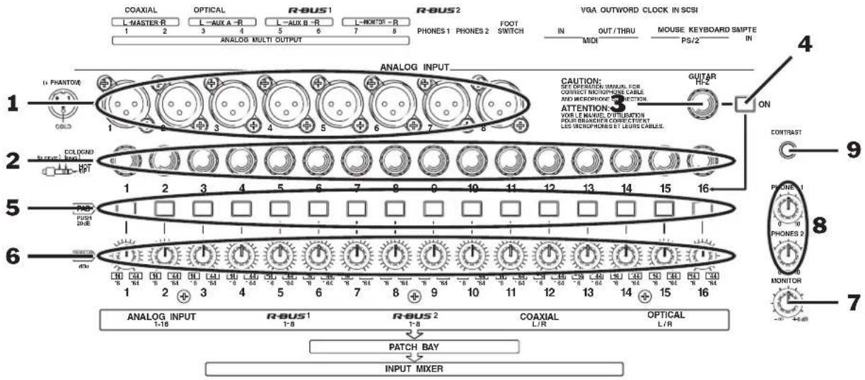
The analog input jacks allow you to bring analog audio into the VS-2480's 24-bit analog-to-digital (A/D) converters using balanced XLR connectors and balanced or unbalanced 1/4" connectors. The VS-2480 also provides -20 dB pads and level sensitivity adjustment knobs for each input jack. We'll explain how to correctly set an analog input's level in "Setting Analog Input Levels" on Page 130.

Don't use the same-numbered XLR and TRS input jack—each pad and SENS knob controls both jacks, so you won't have independent control of the two jacks' signals.

Analog, 24-bit, balanced, XLR, unbalanced, TRS, dB, pad
1—XLR Inputs 1-8
Each of the eight XLR input jacks accepts an input signal from a balanced XLR connector.

The VS-2480 can provide phantom power for a condenser-type mic connected to an XLR jack. See "To Turn an XLR Input Jack's Phantom Power On or Off" on Page 130.
2—TRS Inputs 1-16
Connect a 1/4" phone-type TRS balanced or unbalanced audio connector to any of the sixteen TRS input jacks.
3—GUITAR HI-Z
If you'd like to plug an electric guitar or bass directly into the VS-2480, connect it to the GUITAR HI-Z (for "high impedance") 1/4" phone-type jack for a loud, clean signal with a minimum of noise.


High impedance
You can use either the GUITAR HI-Z input jack or TRS Input 16, but not both at the same time. The setting of the GUITAR HI-Z ON switch determines which of these jacks is turned on.
4—GUITAR HI-Z ON Switch
Press the GUITAR HI-Z ON switch to turn on the GUITAR HI-Z input jack, and to turn off TRS Input 16—when the switch is locked in its "in" position, the GUITAR HI-Z input jack is activated.
5—PAD Switches 1-16
When the PAD button is in its "in" position, the signal in the corresponding XLR or TRS input jack is reduced by 20 dB.

Lower the VS-2480's MASTER fader—and Aux master faders controlling headphone mix levels—before pressing a PAD button to avoid damage to your amp or speakers.
6—SENS Knobs 1-16
You can adjust the sensitivity of an XLR or TRS input jack by turning its SENS—for "Sensitivity"—knob. Turn the knob all the way clockwise for a mic level (-44 dBu) device or all the way counter-clockwise for a line level (+14 dBu) device.

When no input signal is connected or in use, turn each input jack's SENS knob all the way counter-clockwise—and turn on its PAD—to avoid unwanted noise.

Mic level, line level, dBu
Monitor/Display Controls
7—MONITOR Knob
This knob controls the volume of the VS-2480's stereo MONITOR bus and outputs. It can also set the basic listening level of the PHONES 1 and 2 jacks.
8—PHONES 1 AND PHONES 2 Knobs
These knobs control how loudly the VS-2480's MONITOR output is heard through headphones connected to the PHONES 1 and 2 jacks, respectively. To learn how to set your headphone listening level, see "Adjusting Your Listening Level" on Page 75.
9—CONTRAST Knob
The CONTRAST knob allows you to change the contrast of the VS-2480's display. Turn the knob until the display looks its best from your viewing angle.
Channel Strips
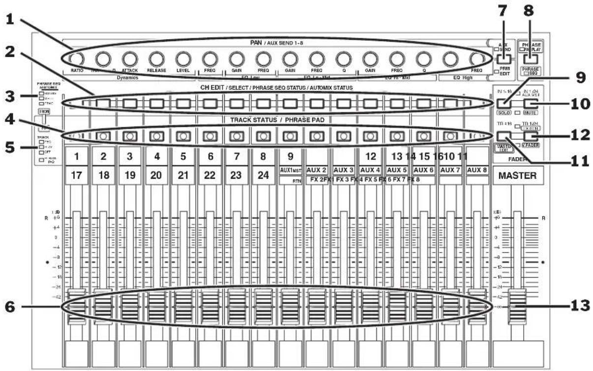
Each of the first sixteen channel strips contains—reading from the bottom up—a fader, a TRACK STATUS/PHRASE PAD button, a CH EDIT/SELECT/PHRASE SEQ STATUS/AUTOMIX STATUS button and a PAN/AUX SEND 1-8 knob. Channel strips are described in detail in Chapters 9. At the right side of this area is the MASTER fader (Page 142).
1—PAN/AUX SEND 1-8 Knobs
These multi-purpose knobs perform several functions, depending on the current color of the AUX SEND•PRM EDIT button (see "7—AUX SEND•PRM EDIT Button" on Page 34).
Each PAN/AUX SEND 1-8 knob controls its channel's panning when the AUX SEND•PRM EDIT button is unlit. You can set the knob to control another channel setting if you wish. See "Using the PAN/AUX SEND 1-8 Knobs" on Page 139.
The PAN/AUX SEND 1-8 knobs are described in detail starting on Page 139.
When using the channel strips as a MIDI control surface—see Page 300—use the knobs to transmit MIDI Control Change messages.
Channel, channel strip, fader, panning, MIDI, MIDI control surface, MIDI Control Change messages


2—CH EDIT/SELECT/PHRASE SEQ STATUS/AUTOMIX STATUS Buttons 1-16
When working with input, track and FX ("effect") return channels, press this button to view a channel's CH EDIT settings—the button lights to show that the input, track or FX return channel is selected. When working in Phrase Sequence or Automix modes, the color of each of these buttons shows the current status of its sequence or Automix track, respectively. See "3—PHRASE SEQ/AUTOMIX Key" below.
3—PHRASE SEQ/AUTOMIX Key
The PHRASE SEQ/AUTOMIX key explains the meaning of CH EDIT/PHRASE SEQ STATUS/AUTOMIX STATUS button colors when working in Phrase Sequence or Automix modes.
4—TRACK STATUS/PHRASE PAD Buttons 1-16, 17-24, AUX MSTR 1-8, FX RTN 1-8
When working with track channels, press this button to set each track channel's status—the current status of the button is shown by its color (See “5—TRACK STATUS Key” below). In Phrase Pad mode, each button acts as a pad you can strike to play a phrase. See “Playing the Pads in Phrase Pad Mode” on Page 275. These buttons are also used when selecting destination tracks during editing.
5—TRACK STATUS Key
The TRACK STATUS key explains the meaning of TRACK STATUS/PHRASE PAD colors so you can tell if a track channel is set to record a track, play a track, do nothing or play a phrase.
6—Channel Strip Faders
Use each channel strip fader to make adjustments to its channel's output level. When using the channel strips as a MIDI control surface—see Page 300—use the faders to transmit MIDI Control Change messages.

You can use the faders to control a variety of settings. See "To Set What the KNOB/FADER ASSIGN Feature Controls" on Page 140.
7—AUX SEND•PRM EDIT Button
The color of the AUX SEND•PRM EDIT button shows what the PAN/AUX SEND 1-8 knobs (Page 33) are set up to do. Press the AUX SEND•PRM EDIT button to change its setting. When the button is:
- Unlit—Each PAN/AUX SEND 1-8 knob controls the PAN setting of its channel.
- Red—Each PAN/AUX SEND 1-8 knob adjusts the value of the setting printed beneath it for the currently selected channel.
- Green—Each PAN/AUX SEND 1-8 knob controls the send level from its channel to the currently selected Aux bus. See “The KNOB/FDR ASSIGN•AUX SEND 1-8 Button” on Page 140 to learn how to set the AUX SEND•PRM EDIT button to green.

An AUX SEND•PRM EDIT button color key is printed above and below the button.
8—PHRASE PAD PLAY•PHRASE SEQ Button
This button activates and de-activates the playing of phrases and the recording of phrase sequences using the TRACK STATUS/PHRASE PAD buttons. When the PHRASE PAD PLAY•PHRASE SEQ button is:
- Unlit—Phrase Pad and Phrase Sequence modes are turned off.
• Green—Phrase Pad mode is activated.
• Red—Phrase Sequence mode is activated. - Flashing red—the phrase sequencer is recording.
9—IN 1-16·SOLO
Press the IN 1-16•SOLO button to assign the sixteen channel strips to Input Channels 1-16 (see Page 137). Hold SHIFT and press IN 1-16•SOLO to enter and exit Solo mode (Page 143).
10—IN 17-24/AUX MST•MUTE
Press the IN 17-24/AUX MST•MUTE button to assign the first eight channel strips to Input Channels 17-24 and the rest to the eight Aux master channels (see Page 137). Hold SHIFT and press IN 17-24•MUTE to enter and exit Mute mode (Page 143.).
11—TR 1-16•MASTER EDIT
Press the TR 1-16•MASTER EDIT button to assign the sixteen channel strips to Track Channels 1-16 (see Page 137). Hold down SHIFT and press TR 1-16•MASTER EDIT to display the MASTER EDIT VIEW screen (Page 207, Page 209).
12—TR 17-24/FX RTN•V. FADER
Press the TR 17-24/FX RTN•V. FADER button to assign the first eight channel strips to Track Channels 17-24 and the rest to the eight FX return channels (see Chapter 17). Hold SHIFT and press TR 17-24/FX RTN•V. FADER to change the mixer into a MIDI control surface (see Page 300).
13—MASTER FADER
The position of the MASTER fader sets the level of the main stereo MASTER mix bus.
Since the MONITOR outputs and the PHONES jacks are typically set to listen to the MASTER mix bus, the position of the MASTER fader also affects your listening level.

Display Area
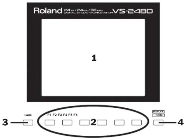
The LCD display and its buttons are central to everything you do on the VS-2480. The F buttons discussed in Chapter 4, on Page 66.
1—LCD Display
The LCD display is your window to all of the VS-2480's operations. In addition to providing you vital information, the display is central to every VS-2480 activity.
2—F Buttons 1-6
The F 1-6 buttons are “soft” buttons whose job changes depending on what you’re doing. When an F button is active, its current function is shown on the display above the button. For more on how the F buttons work, see Page 66.
3—PAGE Button
Some activities on the VS-2480 require more than a single screenful of settings—each screenful is called a "page." For such activities, you can repeatedly press the PAGE button to cycle through the available pages.
4—HOME•DISPLAY Button
Press the HOME•DISPLAY button to return to the VS-2480's Home screen, described in detail in Chapter 8, beginning on Page 119. Hold SHIFT and press the button to change what appears in the playlist area of the Home screen (Page 124).

Although the HOME•DISPLAY button is actually labeled as "DISPLAY•HOME," we call it HOME•DISPLAY to reflect its most typical use.
TRACK EDIT Area
flowchart
graph TD
    A["1"] --> B["2"]
    B --> C["3"]
    C --> D["4"]
    D --> E["5"]
    E --> F["6"]
    F --> G["7"]
    G --> H["8"]

    subgraph Components
        I["Copy"] --> J["DIVE"] --> K["TRI IN"] --> L["TRIO OUT"] --> M["DELETE"] --> N["SPLIT"] --> O["NEW"] --> P["PHRASE"]
        Q["COPY MOVE INSERT OUT ERASE COP / EXP."] --> R["1"]
        S["IMPORT GRADATION"] --> T["2"]
        U["REGION AUTOMIX"] --> V["3"]
        W["LOOPAL/PINENTOR/REFINER"] --> X["4"]
        Y["REDD"] --> Z["5"]
    end

    style Components fill:#f9f,stroke:#333,stroke-width:2px
    style I fill:#ccf,stroke:#333
    style J fill:#ccf,stroke:#333
    style K fill:#ccf,stroke:#333
    style L fill:#ccf,stroke:#333
    style M fill:#ccf,stroke:#333
    style N fill:#ccf,stroke:#333
    style O fill:#ccf,stroke:#333
    style P fill:#ccf,stroke:#333
    style Q fill:#ccf,stroke:#333
    style R fill:#ccf,stroke:#333
    style S fill:#ccf,stroke:#333
    style T fill:#ccf,stroke:#333
    style U fill:#ccf,stroke:#333
    style V fill:#ccf,stroke:#333
    style W fill:#ccf,stroke:#333
    style X fill:#ccf,stroke:#333
    style Y fill:#ccf,stroke:#333
    style Z fill:#ccf,stroke:#333
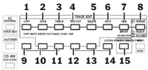
You'll use the top row of buttons in this area as shortcuts when editing the regions and phrases of recorded tracks—the TRACK EDIT buttons are described on Page 247. To learn about tracks, phrases and regions, see Chapter 6, starting on Page 85. To learn about editing phrase and regions, see Chapters 18-20. You'll also use the TRACK EDIT buttons when working with Automix data; see Chapter 26. The buttons you'll need when you want to use the VS-2480's Auto Punch feature or when you want to loop a part of a song are also found in this area.

Tracks, regions, phrases, Automix, Auto Punch, punch, loop
The function of Buttons 1-7 in the illustration above depends on whether you're editing regions, phrases or Automix data, as shown by the color of the PHRASE•REGION
- AUTOMIX button. In the following text, the label above most of the buttons—for phrase editing—appears before the label beneath it that applies to region and Automix editing, which works with regions of Automix data. Two of the buttons have three labels: one each for phrase editing, region editing and Automix operations.
1—COPY•COPY Button
Press this button to copy a currently selected phrase or region.
2—MOVE•MOVE Button
Press this button to move a currently selected phrase or region.
3—TRIM IN•INSERT Button
- When editing a phrase, press this button to change where the phrase begins.
- When editing a region, press this button to insert silence into the selected region, pushing subsequent recorded data back in time.
4—TRIM OUT•CUT Button
- When editing a phrase, use this button to change where the phrase ends.
- When editing a region, press this button to delete the selected region, moving subsequent recorded data forward in time.
5—DELETE•ERASE Button
- When editing a phrase, press this button to delete the phrase from the track without affecting its other audio.
- When editing a region, press this button to clear the selected region of all data.
6—SPLIT•COMP/EXP Button
- When editing phrases, press this button to split the selected phrase at the timeline.
- When editing regions, press this button to perform time compression or expansion on the currently selected track region, or scaling of automated parameter values.

Timeline
7—NEW•IMPORT•GRADATION Button
- When editing phrases, press this button to create a new phrase from a recorded take on your hard drive.
- When editing regions, press this button to copy a recording from a different project (Page 56) into the current project.
- When using Automix, press this to view the Gradation dialog (Page 337).
8—PHRASE•REGION•AUTOMIX Button
Press this button to select the type of editing you wish to do: phrase, region or Automix editing. The color of the button—as shown in the key to its left—shows the currently selected type of editing:
• Green—phrase editing •
• Red—region editing
Orange—Automix editing
9—A. PUNCH Button
Press this button to activate (lit) or de-activate (unlit) Auto Punch. See Page 192.
10—IN Button
Press the IN button to set the current position of the timeline as the start of a region of data you want to edit, or as the punch-in location when holding down A.PUNCH.
11—OUT Button
Press the OUT button to set the current position of the timeline as the end of a region of data you want to edit, or as the punch-out location when holding down A.PUNCH.
12—FROM Button
Press FROM to select the current position of the timeline as a time-reference point in a section of data to be moved or copied. When looping, press FROM while holding down LOOP when the timeline's at the location you want to use as the start of your loop.
13—TO Button
Press TO to select the current position of the timeline as a location at which you want the FROM point to be placed when data is moved or copied. When looping, press TO while holding down LOOP when the timeline's at the location you want to use as the end of your loop.

IN, FROM, OUT and TO work together, playing a part in a variety of editing operations. They're discussed as a group in Chapter 18, on Page 236.
14—LOOP Button
Press this button to turn looping on (lit) or off (unlit). See Page 181.
15—WAVE DISPLAY Button
Press WAVE DISPLAY to view the currently selected track's audio as waveform data (lit) or as a simple rectangle (unlit).

Waveform data
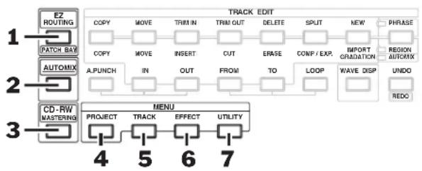
EZ ROUTING, AUTOMIX, CD-RW/MASTERING and MENU Buttons
flowchart
graph TD
    A["1. EZ ROUTING"] --> B["2. PATCH BAY"]
    B --> C["3. AUTOMIX"]
    C --> D["4. CD-RW MASTERING"]
    D --> E["5. MENU"]
    E --> F["6. EFFECT"]
    F --> G["7. UTILITY"]
    H["1. COPY"] --> I["2. COPY"]
    I --> J["3. A.PUNCH"]
    J --> K["4. PROJECT"]
    K --> L["5. TRACK"]
    L --> M["6. EFFECT"]
    M --> N["7. UTILITY"]
    O["1. MOVE"] --> P["2. MOVE"]
    P --> Q["3. INSERT"]
    Q --> R["4. OUT"]
    R --> S["5. FROM"]
    S --> T["6. TO"]
    T --> U["7. LOOP"]
    U --> V["8. WAVE DISP"]
    V --> W["9. UNDO"]
    W --> X["10. REDO"]
    Y["1. TRIM OUT"] --> Z["2. CUT"]
    Z --> AA["3. ENTER"]
    AB["1. DELETE"] --> AC["4. INPUT"]
    AD["SPLIT"] --> AE["5. OUTPUT"]
    AF["NEW"] --> AG["6. END"]
1—EZ ROUTING Button
Press the EZ ROUTING button to set up, load and save signal routings in the VS-2480:
To learn about see:
Routing input signals to input channels Chapter 9
Routing input channels to tracks Chapter 12
Recording tracks onto other tracks Chapter 14
Routing FX return channels to tracks Chapter 17
Configuring the digital inputs Chapter 9
Activating and de-activating phantom power Chapter 9
Setting up output signals Chapter 22
Sending channels to the internal effects Chapter 16
Saving and loading EZ Routing templates Chapter 23
Clearing routings Chapter 23
Initializing routings Chapter 23

Routing
2—AUTOMIX Button
Press this button to turn Automix on (lit) or off (unlit). Hold down SHIFT and press AUTOMIX to view the Automix edit screen. See Chapter 26, starting on Page 325.
3—CD-RW•MASTERING Button
Press this button to view the CD-RW/MASTERING menu. From there you can enter the VS-2480's Mastering Room—where you can complete the master mix of a project and create an audio CD—play audio CDs on a connected Roland CD-R/RW drive or import and export .WAV files. See Chapter 27, starting on Page 339.

Mastering, CD-R/RW drive
4—PROJECT Button
When you press PROJECT, a menu appears in which you'll find an assortment of project-management tools and tools for working with your internal IDE drive and a connected Zip drive.

IDE, hard drive, removable disk drive
5—TRACK Button
Press the TRACK button to view the TRACK region and phrase editing menus.

The TRACK region and phrase editing menus work hand-in-hand with the TRACK EDIT area buttons described beginning on Page 37.
6—EFFECT Button
Press EFFECT to set up the VS-2480's internal effects. Chapter 5 discusses important underlying effects concepts. Chapter 16 provides the specifics on using the VS-2480's internal effects.
7—UTILITY Button
The UTILITY button provides access to the UTILITY menu, which offers a wide variety of settings that determine the behavior of the VS-2480. See Chapter 28, starting on Page 359.
General Controls

This area contains frequently used controls that are part of many VS-2480 operations.
1—MIDI/DISK Indicator
The MIDI/DISK indicator lights:
• Green—whenever the VS-2480 receives MIDI data from an external device.
- Red—whenever the internal IDE drive is being read or being written to.
2—SHIFT Button
Many of the VS-2480's buttons have a secondary function. When you hold SHIFT and press one of these buttons, the button performs the function shown in its boxed label. See Page 68 for more information on using the SHIFT button.
3—ENTER/YES Button
Press ENTER/YES in response to a yes/no question shown on the display, to execute a procedure, mark an item currently selected on the display or select data for editing.
The ENTER/YES button often flashes to underscore that you're being asked a question on the display or that further options are available for your current activity.
4—EXIT/NO Button
Press EXIT/NO in response to a question on the display, to cancel an operation, exit the current screen or un-mark an object currently selected on the display.
The EXIT/NO button often flashes to underscore that you're being asked a question on the display.


5—TIME/VALUE Dial
The TIME/VALUE dial—located inside the SHUTTLE ring—performs two important jobs:
- During project playback, you can turn the dial to move forward or backward in time. See Page 126 for more information.
- Turn the TIME/VALUE dial to adjust settings.
6—SHUTTLE Ring
Turn the SHUTTLE ring—the wheel that surrounds the TIME/VALUE dial—to move quickly back (counter-clockwise) or forward (clockwise) through a project. See “The SHUTTLE Ring” on Page 178 for details.
7—◀ ▶ ▲ ▼ (Cursor)/ZOOM Buttons
Press the ◀, ▶, ▲ or ▼ cursor buttons to move the selection cursor (Page 65) around the VS-2480's display.
Hold down SHIFT and press the desired arrow button to zoom in and out on track data shown in the playlist area of the Home screen (Page 119) and other screens:
- Press to increase the horizontal magnification.
- Press to decrease the horizontal magnification.
- Press ▲ to increase the vertical magnification.
- Press ▼ to decrease the vertical magnification.
8—UNDO•REDO Button
The VS-2480 allows you to reverse—or “undo”—up to 999 of your last recording or editing actions. Press the UNDO•REDO button to view the Undo dialog. After undoing any action, you can also “redo” it by pressing UNDO•REDO while holding down SHIFT—the Redo dialog appears.
SCRUB, PREVIEW and Transport Buttons

flowchart
graph TD
    A["1 SCRUB"] --> B["2 Preview"]
    B --> C["3 FROM"]
    C --> D["4 EXT SYNC"]
    D --> E["5"]
    F["6 ZERO STOP PLAY REC"] --> G["7 CRUIT"]
    G --> H["8 ACT"]
    H --> I["9 AUTO RECORDS ARTIST REC"]
1—SCRUB Button
When you need to precisely locate a moment in a track, press SCRUB to activate the Scrub feature. When SCRUB is lit, you can turn the TIME/VALUE dial to move the timeline and listen to a tiny piece of the track play over and over—this lets you zero in on just the moment you're looking for. This can be very helpful when editing. To turn off scrubbing, press SCRUB again so its light goes out. See Page 184 to learn more.
2—PREVIEW TO•PROJECT TOP Button
Press PREVIEW TO to listen to the last few moments leading up to the current location of the timeline—you can set how much you want to hear. Hold SHIFT and press PREVIEW TO to jump to the start, or "top," of the audio recorded in the project.
3—PREVIEW THRU Button
Press PREVIEW THRU to listen to a small chunk of audio leading up to the current location of the timeline and a small chunk that plays after it, as determined by the PREVIEW TO and PREVIEW FROM time settings.
4—PREVIEW FROM•PROJECT END Button
Press PREVIEW FROM to listen to what occurs just after the current location of the timeline—you can set how much you want to hear. Hold SHIFT and press PREVIEW FROM to jump to the end of the audio recorded in the project.
PREVIEW TO, PREVIEW THRU and PREVIEW FROM work together, and are all described in detail in "Preview" on Page 183.
5—EXT SYNC Button
Press EXT SYNC so that it lights to synchronize the VS-2480's playback to an external MTC- or SMPTE-generating device. Press it again so that it's not lit when you want the VS-2480 itself to provide the master timing reference (this is the VS-2480's normal operating mode). Synchronization is described in Chapter 24. Hold down SHIFT and press EXT SYNC to jump to the VS-2480's synchronization settings.
MTC, SMPTE
6—ZERO•STORE Button
Press ZERO•STORE to return to the beginning of the project (Time 00h00m00s00f00)—see Page 126. Hold down SHIFT and press ZERO•STORE to save the current state of your project to your hard drive.
7—STOP•SHUT/EJECT Button
Press STOP to halt playback at the timeline's current location—see Page 122. Hold down SHIFT and press STOP•SHUT/EJECT to power down the VS-2480—you'll be asked if you want to save your project first—and to eject any mounted Zip drive cartridges.
8—PLAY•RESTART Button
Press PLAY•RESTART to begin playback from the current location of the timeline—see Page 122. Hold down SHIFT and press PLAY •RESTART to restart the VS-2480 instead of turning it off after you've performed a shutdown procedure (SHIFT + STOP•SHUT/EJECT).
9—REC•AUTOMIX REC Button
Hold down REC•AUTOMIX REC and press PLAY to record audio onto a track (see Page 179). When the AUTOMIX button (Page 39) is lit, hold down REC•AUTOMIX and press PLAY to record mixer settings as Automix data—see Chapter 26 (Page 325) to learn about automated mixing on the VS-2480.

Realtime
LOCATOR/MARKER/SCENE Area
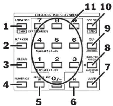

The buttons in this area are described in detail in Chapter 13, starting on Page 177, except as noted.
1—LOCATOR·BANK Button
Press the LOCATOR•BANK button so it's lit to store and recall locators using the numeric keypad (see "11—Numeric keypad•AUX 1-8, USER" on Page 46). A locator remembers a particular timeline position within a project—when you recall the locator, the timeline instantly jumps back to that time position. Locators are discussed in detail in "Locators" on Page 185.
Each project can contain up to 100 locators arranged in groups, or "banks," of ten locators each. To select a locator bank, hold down SHIFT, press LOCATOR•BANK so it's lit, and press the desired bank's number on the numeric keypad.
2—MARKER Button
Press the MARKER button so it's lit to create and recall markers using the numeric keypad (see "11—Numeric keypad•AUX 1-8, USER" on Page 46). Each project can contain up to 1,000 markers, numbered from 000 to 999. Markers are used for navigation during editing, looping and punching. Special markers are used for track indexing when creating an audio CD.
3—CLEAR Button
To delete a locator, marker or scene, hold down CLEAR and press the desired locator, marker or scene (Page 144) number on the numeric keypad.
4—NUMERICS Button
Press NUMERICS so that it lights to enter numeric values for various settings using the VS-2480's keypad or a connected ASCII keyboard. When NUMERICS is lit, the area into which you can type becomes selected on the display. See Page 74.
5—PREVIOUS Button
Press PREVIOUS to move the timeline to the beginning of the currently selected track phrase or to the end of the phrase immediately before it. Hold down SHIFT and press PREVIOUS to move the timeline back in time to the nearest marker.
6—NEXT Button
Press NEXT to move the timeline to the end of the currently selected track phrase or to the beginning of the phrase immediately after it. Hold down SHIFT and press NEXT to move the timeline forward in time to the nearest marker.
7—JUMP Button
You can jump to any location in a project by pressing JUMP and entering the desired time location on the VS-2480's numeric keypad or TIME/VALUE dial. You can select the desired time in time code (01:01:01:01.01) at the left of the dialog that appears, or measures, beats and clocks (001-01-001) at the right. Press ENTER/YES to move to the selected location.
8—KNOB/FDR ASSIGN•AUX SEND 1-8 Button
When you press the KNOB/FDR ASSIGN•AUX SEND 1-8 button so that it flashes, you can press a number on the numeric keypad to assign the PAN/AUX SEND 1-8 knobs to the job of sending signals from the individual channel strips (Page 33) to the corresponding Aux bus. In addition, you can press 9•USER to assign them to another setting of your choice. See Page 141.
Press TAP•SNAPSHOT to create a marker at the current position of the timeline—the marker is numbered automatically. When AUTOMIX (Page 325) is lit, press AUTOMIX and this button to create a snapshot of your current mixer settings that can be recalled as part of an automated mix. Automix and snapshots are discussed in Chapter 26. Hold down CD-RW•MASTERING and press TAP•SNAPSHOT to place a CD track marker at the timeline's current location.
10—SCENE·BANK Button
Press the SCENE•BANK button so it's lit to store and recall scenes using the numeric keypad (see "11—Numeric keypad•AUX 1-8, USER" on Page 46). A scene stores your current mixer settings, allowing you to save different versions of your project for instant recall. Scenes are discussed in detail in "Scenes" on Page 144.
Each project can contain up to 100 scenes in groups, or "banks," of ten scenes each. To select a scene bank, hold down SHIFT, press SCENE•BANK so it's lit, and press the desired bank's number on the numeric keypad.
11—Numeric keypad•AUX 1-8, USER
The numeric keypad serves two general purposes:
- You can type the desired number or numbers on it when storing and recalling locators, scenes and markers, or when entering values when NUMERICS is lit.
- When KNOB/FDR ASSIGN•AUX SEND 1-8 is flashing, you can assign the PAN/AUX SEND 1-8 knobs to the job of sending signals from the individual channel strips to one of the eight Aux busses (Page 141) by pressing the desired 1-8 button, or to some other job by pressing 9•USER (also Page 141).

Bus

Every set of ten items on the numeric keypad—banks, locators, scenes and so on—is numbered from 0 to 9.
The Rear Panel of the VS-2480
1—POWER Switch
Use the POWER switch to turn the VS-2480 on and off.

Don't simply flip the POWER switch when you want to shut down the VS-2480—if you do this, data loss may occur. Make sure to use the proper shutdown procedure, described on Page 80.
2—AC IN Jack
Connect one end of the supplied AC power cord to a grounded AC outlet, and the other end to the AC IN jack.


Use only the supplied AC power cord to prevent damage to your VS-2480.
3—Cooling Fan Exhaust Vent
The VS-2480 contains a cooling fan that prevents it from overheating. The fan expels hot air through this exhaust vent.

Be sure never to block the cooling fan exhaust vent. If hot air from the VS-2480 chassis isn't allowed to escape through this vent, the VS-2480 may overheat and be damaged.
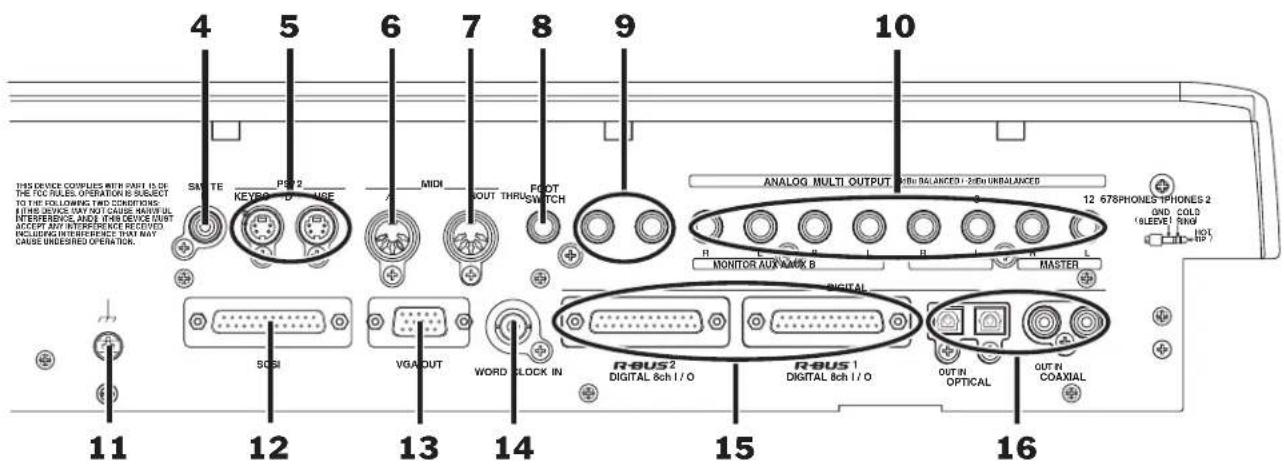
4—SMPTE IN Jack
When synchronizing the VS-2480 as a slave to an external SMPTE-generating device, connect the external device's SMPTE output to the VS-2480's SMPTE IN jack. Synchronization is discussed in Chapter 24, starting on Page 307.
?
Slave
5—PS/2 KEYBOARD and MOUSE Jacks
Connect a PS/2 ASCII keyboard (purchased separately) and mouse (shipped with the VS-2480) to the PS/2 KEYBOARD and MOUSE jacks, respectively. See Page 62.
?
PS/2, ASCII
By default, this jack functions as a MIDI output jack—connect it to the MIDI input of any device to which you wish to send MIDI data from the VS-2480 (see Chapter 24, Page 299). You can also set the MIDI OUT/THRU jack to function as a THRU jack that passes along any MIDI data the VS-2480 receives from an external device (Page 300).
7—MIDI IN Jack
Connect the MIDI output of an external device to the MIDI IN jack when you want the VS-2480 to receive and respond to MIDI data transmitted from an external device. See Chapter 24, starting on Page 299.
8—FOOT SWITCH Jack
You can control a variety of VS-2480 functions using an optional foot switch—such as a Roland DP-2 or BOSS FS-5U—connected to this jack. See Page 362.
9—PHONES 1 and 2 Jacks
Connect standard stereo headphones (purchased separately) to either or both of these jacks for listening to the VS-2480. Each jack has its own volume control (Page 75). You can select the signals to be sent to the PHONES jacks, as described in Chapter 22.
10—ANALOG MULTI OUTPUT Jacks 1-8
These are the VS-2480's line-level analog output jacks. When used with balanced cables, they produce a +4dBu level; when used with unbalanced cables, they produce a level of -2dBu.

The label for each pair of jacks shows its factory default setting. However, you can assign different signals to the jacks if you wish. See Chapter 22, starting on Page 287.
11—Grounding Terminal
In rare cases, you may feel a slight electrical current when you touch the case of the VS-2480. While completely harmless, you may want to connect the VS-2480's grounding terminal to an external ground to eliminate the sensation. There's a slight risk, however, that grounding the VS-2480 will cause a low-level hum to occur.

There are a few external grounding sources you should never attempt to use. Do not connect the grounding terminal to water pipes, which can cause shock, or even electrocution. Don't ground the VS-2480 to gas pipes—this can result in fire or explosion. And don't connect the terminal to a telephone jack or lightning rod, which can be dangerous in the event of lightning.
12—SCSI Jack
The VS-2480's SCSI jack is a DB-25-type SCSI connector to which you can attach a SCSI cable connected to Roland CD-RW drive or compatible drive. You'll find some tips for successful SCSI connections in the VS-2480 Appendices.
13—VGA OUT Jack
Connect an external VGA CRT color video monitor—purchased separately—to this DB-15-type VGA output jack. The monitor's Info Display provides helpful large-screen information about a variety of VS-2480 operations. You'll find setup details on Page 64 and an introduction to the Info Display screens on Page 70.
14—WORD CLOCK IN Jack
When synchronizing the VS-2480's signal to a group of external digital devices, connect the master timing source's word clock output to the VS-2480's WORD CLOCK IN jack using a standard BNC cable.

Word clock
15—R-BUS 1 and 2 DIGITAL 8ch I/O Jacks
Using Roland's R-BUS technology, you can bring digital audio into and out of the VS-2480 by connecting it to any R-BUS-compliant external digital device. This includes the following Roland products (purchased separately):
- ADA-7000 8-Channel A/D-D/A Converter that provides additional analog inputs
• AE-7000 AES/EBU Interface that provides AES-EBU connectivity - The RPC-1 R-BUS Interface Card for exchanging digital audio with a computer
• The VM-7000 V-Mixing system
• The VM-3100Pro V-Mixing Station - XV-5080 128-Voice Synthesizer/Sample Playback Module
To connect the VS-2480 to another R-BUS device, connect one end of an R-BUS cable to the VS-2480's R-BUS 1 jack or R-BUS 2 jack, and the other to an R-BUS jack on the external device.
Be sure to use the shortest Roland-approved R-BUS cables possible. Note that other cables—such as SCSI, RS-232C or parallel cables—may have connectors that look like R-BUS connectors, but they're not the same, and these cables can't be used successfully with R-BUS jacks.


If you plan to use only one of the VS-2480's R-BUS jacks, use the R-BUS 1 jack, whose eight channels of digital audio are always available. The full set of eight channels associated with the R-BUS 2 jack is available only when you're not using the coaxial and optical digital inputs, as described on Page 131.
Each R-BUS jack can both receive and send eight separate digital audio signals, so only one connection is needed between two R-BUS devices. R-BUS connections can also carry MIDI, MMC and MTC data in both directions.

MMC
See Page 377 to learn how to configure a connected R-BUS device. Page 131 describes how to activate R-BUS 2, coaxial and optical inputs. See Page 288 to learn how to route the desired signals to your R-BUS outputs.

R-BUS was formerly called "RMDB II" or "RMDB2" in earlier Roland products.
16—OPTICAL and COAXIAL Digital Audio Connectors
The VS-2480 can both receive and transmit S/P DIF-format digital audio via its optical and coaxial digital IN and OUT connectors. Each connector carries a stereo digital audio signal. See Page 132 to learn how to successfully handle incoming digital audio. We'll explain how to route signals to either OUT connector starting on Page 288.

S/P DIF

You can configure the VS-2480 to record digital audio received from an external digital device connected to these jacks—see Page 134.

The coaxial IN and OUT jacks carry only S/P DIF digital audio signals. The IN jack won't accept standard analog audio signals, and the OUT jack doesn't produce them.
3—Introduction to the VS-2480
To master the VS-2480, it's important to understand the components that make up this self-contained 24-track recording studio. That's what we'll do here. More specific descriptions of how to use these components can be found in later chapters as noted.
While advanced V-2480 users may already understand much of what's discussed here, everyone should make sure to read "Projects" on Page 56. This section introduces the project, the basic structure in which all VS-2480 work takes place.
What's Inside the VS-2480?
Every recording studio has the same mission: the capturing of sound and the conversion of that sound into a form—an audio CD, a film or video soundtrack, a broadcast—that people can hear. If you were to go into any conventional multitrack recording studio, you’d therefore see the same sort of tools. All of these tools can also be found inside your VS-2480. Here’s what’s hidden inside its case:
Input jacks and connectors
Mixing console Internal effects

natural_image
Illustration of a rack with multiple vertical binders and a vertical stand (no text or symbols)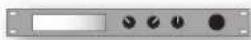
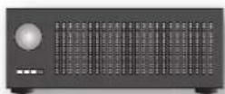
Hard disk recorder
Output jacks and connectors
Input Jacks and Connectors
Obviously, you've got to have a way to get sound into the VS-2480.
Analog and digital sounds travel through the cables that bring them to the VS-2480 as electrical signals, called “input signals.” The VS-2480 provides jacks that recognize analog audio signals from microphones and from electric or electronic instruments. It also has digital connectors that accept digital audio signals from devices such as synthesizers or effect boxes with digital outputs, and from digital audio tape (DAT) decks and other kinds of digital recorders, including computer-based audio recorders. We’ll discuss the VS-2480’s analog input jacks and digital connectors in detail in Chapter 9, starting on Page 129.
The Mixing Console
The VS-2480 contains a digital 64-channel mixing console.
What's a Digital Mixing Console?
First, let's make sure we understand what a mixing console, or "mixer," is. A mixer is a device that lets you manipulate audio, and lets you combine multiple audio signals into a single sound, or a "mix." That mix can be in mono, stereo or Surround.
A digital mixer converts all audio signals into binary data—numbers—and performs all of its operations using complex mathematical equations. When you listen to the mixer—and any time audio comes out of its analog outputs—the sound is converted back into audible form. A digital mixer has several powerful advantages:
- Digital mixers produce extremely high-quality sound.
- They can memorize settings that can be restored with the touch of a button.
- They have a flexible internal structure—it's all just numbers under the hood, after all, not physical wires—so you can easily re-configure the mixer's internal connections in ways that aren't possible with a traditional analog mixer.
64 Channels?
In the VS-2480, each audio signal has its own set of controls with which you can manage and shape its sound. This set of controls is called a “channel.” The VS-2480’s mixer has 64 channels, all of which are always active and available:
- 24 input channels—control signals received by 24 of the VS-2480's analog input jacks and digital connectors. The 24 input channels are sometimes collectively referred to as the "input mixer."
- 8 Aux master channels—control the master volume, or "level," of the eight Aux busses. We'll explain the Aux busses in Chapter 15.
- 24 track channels—control the sound of recordings being played back by the VS-2480's hard disk recorder. They may be referred to as the "track mixer."
- 8 FX return channels control the sound produced by the VS-2480's internal effects.

As you can see, there are just 16 physical channel strips—plus the MASTER strip—on the VS-2480. If it actually had 64 physical channel strips, the VS-2480 would behuge.
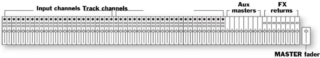
Even so, all 64 channels are available at all times. Here's how this is possible.
Once you've set a channel's controls the way you want them, the channel does its job without further action on your part—you only need to get to its controls when you want to change their settings. On the VS-2480, when you need to change a particular channel's settings, you press a FADER button, and the controls belonging to one of the physical channel strips become the controls for the selected channel.
We'll discuss the operation of the mixer in detail in Chapter 10, starting on Page 137.
The Main Roles of the VS-2480 Mixer
Two of the most important jobs the mixer performs in the VS-2480 are this:
It helps you make an input signal sound the way you want it to on its way to a track.
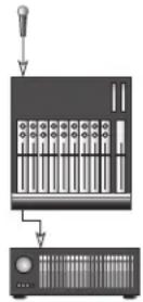
It helps you get the track to sound the way you want, both during recording and while it's being played back when you're mixing or bouncing.
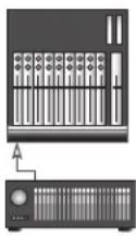
You'll also use the VS-2480's mixer to:
- mix input signals for your performers to listen to in headphones or stage monitors.
- send input signals to the VS-2480 internal effects.
- set the amount of internal effects processing you want to add to your input signals.
- control the level of input signals sent to external devices for effect processing, and the sound of what comes back into the VS-2480 from the external devices.
- listen to the hard disk recorder's tracks as you record so that you can hear what they're recording.
- send tracks to the internal effects.
- set the amount of internal effects processing you want to hear on your tracks.
- control the level of tracks sent to external devices for effect processing, and the sound of what comes back into the VS-2480 from the external devices.
- create a mix to send to a house public address (PA) system when you're using the VS-2480 for live recording in a club or concert hall.
What all of these jobs have in common is that all involve the same basic abilities in the mixer. The mixer lets you:
• control the level of all kinds of audio.
- set the audio's stereo or Surround positioning between your speakers.
- change the tonal characteristics of audio with equalization, or "EQ."
- apply dynamics processing to audio to change the way it gets louder or softer.

Bouncing, equalization, EQ, dynamics processing
MIDI Control Surface
When the VS-2480's V.Fader feature is active, you can use each channel strip's fader and its PAN/AUX SEND 1-8 knob to send MIDI Control Change messages to an external MIDI device. This can be especially handy when you're using the VS-2480 with a MIDI sequencer. You can use the mixer to work the sequencer's controls directly from the VS-2480. See "V.Fader—The VS-2480 MIDI Control Surface" on Page 300 to learn more about using the mixer as a MIDI control surface.
The Internal Effects
What Are the Internal Effects?
The VS-2480 contains a set of individual internal effects processors. As shipped from the factory, there are two internal stereo effect processors onboard. You can install up to three additional VS8F-2 Effect Expansion Boards (purchased separately) for a total of eight internal stereo effect processors.
What Are Effects?
An effect is a type of audio processing that's added to a sound to enhance it. There are a variety of effects available in the VS-2480, including:
- Reverbs—A reverb adds an ambience to a sound, creating the impression that it exists in an actual physical space. Some people call reverb “echo,” though technically that word applies to something else, as we’ll see. A reverb can be short in duration—so that it sounds like an average-sized room in your home—or long, so that it sounds like big concert hall. It can also be set to any size in-between.
- Delays—A delay causes the original sound to repeat one or more times, often at levels that get quieter and quieter with each repeat. Long delays help re-create classic rock 'n roll sounds. Any delay can also useful for subtly suggesting an ambience. Another word for "delay" is "echo."
- Choruses, flangers and phasers—All three effects add their own type of swirling texture to a sound, most often to instruments such as electric pianos and electric guitar or bass. They utilize subtle delays and/or pitch changes to do what they do.
- Filters—A filter removes part of the original sound. This group of effects includes EQs and things like wah-wah pedal simulations.
- Compressors, limiters, gates—These effects, collectively called “dynamics processors,” alter the volume of the original signal in one way or another. Compressors and limiters even out volume fluctuations, while a gate lowers the level of a signal—or shuts it off altogether—when it falls below a certain volume level.
- Modeling—Roland's COSM™ (Composite Object Sound Modeling) process emulates various guitar amps, microphones and speakers with amazing realism.
The VS-2480 also offers effects that use several of these audio processes at once.
How Does the VS-2480 Create Effects?
Each of the VS-2480's effects is created by subjecting an audio signal—remember, it's just numbers while it's inside the VS-2480—to a complex mathematical formula called an "algorithm." The VS-2480 contains 36 algorithms. You'll find a list of them in the VS-2480 Appendices booklet.
Each algorithm has its own collection of settings. You can save an algorithm's settings in the VS-2480 memory as an "effect patch." The VS-2480 ships from the factory with 250 pre-programmed patches, many of which offer more than one kind of effect. The VS-2480 also provides 200 memory locations into which you can save your own effect patches. See the VS-2480 Appendices for a list of the factory effect patches.
Effects can be applied to an audio signal in either of two ways, as we'll discuss in Chapter 5, starting on Page 81.
The Hard Disk Recorder
The VS-2480's hard disk recorder is the simplest of its three major components to explain and understand—it's an audio recorder, acting a lot like a cassette recorder, VCR or any other traditional kind of recorder. Its basic controls will be familiar to you. Instead of recording on a cassette or VHS tape, however, the hard disk recorder records audio onto a computer hard disk drive (Page 85). This provides some important advantages over other kinds of recorders:
- Its sound quality is excellent.
- You can instantly jump to any location in a recording with no waiting while the machine fast-forwards or rewinds.
- You can easily manipulate recorded audio, copying it, pasting it, moving it, time-stretching it and much more.
- You can edit audio "non-destructively," with the ability to undo any edit you make.
- The VS-2480 can memorize multiple locations within a recording so that you can jump back and forth between sections in a heartbeat.
How Many Tracks Can It Record?
The hard disk recorder can record up to 16 tracks at once, and play back up to 24 tracks at a time. That's really only the beginning of the story, though, since each project on the VS-2480 can actually contain 384 "Virtual Tracks" from which you can pick and choose.
The words “track” and “Virtual Track” have special meanings in the VS-2480. We’ll discuss them in Chapter 6.
The number of tracks you can record and play at once is determined by the selected recording mode, as you'll learn in Chapter 7.
We'll discuss how to use the hard disk recorder in Chapter 13, starting on Page 177.
The Phrase Pads
The audio recorded on a particular track can be divided up into phrases (Chapter 6). Normally, these phrases play back when you press the hard disk recorder's PLAY button. However, you can also play a phrase on a track by striking the corresponding track channel's TRACK STATUS/PHRASE PAD button. You can also record your strikes as a performance captured by the VS-2480's phrase sequencer. See Chapter 21 on Page 273 to learn more about the phrase pads and phrase sequencer.
Output Jacks and Connectors
If you've got a Roland VS-CDRII or CD-RACK (purchased separately) connected to your VS-2480's SCSI jack, you can burn your own audio CDs directly from the VS-2480. However, there are lots of reasons you might want to get audio out of the VS-2480. You may want to:
- send your MASTER mix to a pair of monitors so you can hear what you're doing.
- send input signals or tracks to an external effect processor.
- send tracks to a computer for further editing or other purposes.
- send signals to a headphone amplifier to give your performers a way to hear what's being recorded during a recording session.
- send signals to a stage monitors to let your performers hear what they're playing or singing when using the VS-2480 for live recording.

The VS-2480 provides analog output jacks and digital connectors for all of these situations. We'll discuss them in detail in Chapter 22, starting on Page 287.

Burn
Signal Flow
Here's an illustration that shows, in general terms, how signals typically flow in the VS-2480. You can see how the inputs, input channels, hard disk recorder, track channels and outputs work together:
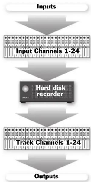
flowchart
graph TD
    A["Inputs"] --> B["Input Channels 1-24"]
    B --> C["Hard disk recorder"]
    C --> D["Track Channels 1-24"]
    D --> E["Outputs"]
There are several places at which you can add effects to signals—the effects processor isn't shown in this illustration for visual clarity.
Projects
Everything you do in the VS-2480 takes place inside something called a “project.” As its name suggests, a project is a hard disk file that contains all of the information for a particular work or performance you’re creating. That work could be a song, a soundtrack, a broadcast, a jingle or anything else. It could even be the music for an entire CD, containing multiple songs, or a set of songs recorded live.

In other V-Studios—such as the VS-1880, VS-890, VSR-880 and VS-840GX—projects are called "songs."
Projects provide an easy way to keep all the materials for a particular piece in one place, ready to go when you need them, including:
- everything you've recorded.
- your most recent mixer settings, as well as any alternate mixer setups you've saved.
- your effect settings.
- all locations you've saved for use in navigation, punching and looping.
-
all Automix data.
-
playback speed settings.
- all information relating to tempo and synchronization.
- all project-related UTILITY menu settings.
The VS-2480 always has a project loaded, even if you've never created one yourself.
A projects can be as large as space allows, as long as it doesn't exceed the maximum number of allowable events (see below.) You can save up to 200 projects on your hard drive, space permitting. You can change from project to project by loading the project you want to work on as needed. You can also copy data between projects. Project operations are discussed in Chapter 7 on Page 93.
We'll describe how to create and name a new project in Chapter 7.

If the intended final destination for your project is an audio CD, be sure to select a 44.1kHz sampling rate for your project when you create it—see Page 339.
About Events
The smallest chunk of project data that the VS-2480 works with is called an “event,” a piece of information that the VS-2480 needs to do its job. For example, each recording you make uses up at least two events: one that tells the VS-2480 where on the hard drive the recording’s file starts, and one that tells it where it ends. Each project can contain roughly 10,000 events—when all of its events have been used up, the project is full, even if you have disk space left. You can trim the number of events in a project by “optimizing” it, as discussed in Chapter 7.
Busses in the VS-2480
In order to get signals from one place to another within the VS-2480—and to provide a way to get them out of the VS-2480—the VS-2480 uses an assortment of “busses.” While we’ll describe the use of the VS-2480’s busses in various places throughout the VS-2480 Owner’s Manual, it’s important to first understand what a bus is.
What's a Bus?
A bus is a pathway down which one or more signals can travel to a common destination.

In older analog mixers, a bus was literally a single wire into which signals were fed—the wire was then connected to the desired destination's input.
This simple mechanism is more significant than it may seem since it lets you send a group of signals to a track, into a mix, to an effect, to specific outputs and more. Much of the VS-2480's bussing occurs behind the scenes—so you won't always be dealing directly with it—but some of its busses play an important, visible role in its operations.
Although every bus is essentially the same thing—a pathway—busses are named for the type of signal they typically carry. The VS-2480 provides the following busses.
Type of bus: What it does:
RECORD Each of these 24 busses carries signals to one of the hard disk recorder's tracks.
MASTER This stereo left/right pair of busses carries the VS-2480's main stereo mix to any number of possible destinations.
MONITOR This stereo left/right pair of busses carries signals to your listening device: monitor speakers or headphones
AUX "AUX" is short for "Auxiliary Send." The eight AUX busses carry signals to the VS-2480's internal effects. They can also carry signals to outputs connected to external devices such as effect boxes or headphone amplifiers for your performers.
DIR "DIR" is short for "Direct bus." Unlike most busses, the eight Direct busses don't carry groups of signals—each one provides a way to route a single signal directly to one of the VS-2480's internal effects, or to an output and an external device.

Don't be confused by the name "R-BUS." R-BUS isn't a kind of bus—it's Roland's own digital connector format. Of course, you can route some of the VS-2480's busses to the VS-2480's R-BUS connectors (Page 288) to send them to an external digital device.
Achieving Perfect Levels
In all digital recording, the best sound is achieved when a signal is at just below 0 dB in level so that the audio takes fullest advantage of the recording device's available bit depth. You need to be careful, though: If the signal exceeds 0 dB, the signal will "clip."

Bit depth
What's "Clipping?"
Clipping is the introduction of clicking and other noises when a signal's too loud. There's no really good way to get rid of these noises once they've been recorded. You may have some success importing the audio into a wave editor with de-clicking tools, but it's best to avoid clipping in the first place.
How Do I Get Good Levels?
The goal, therefore, is to capture as loud a signal as possible without exceeding 0 dB. Achieving a loud-but-not-too-loud signal is the challenge of digital recording. When you're working with audio that has a consistent, predictable dynamic range, it's not hard to accomplish. However, if your project swings wildly between loud and soft passages—or if you're recording musicians whose volume changes a lot—it can be a bit more tricky.
Take Care During Recording
When it comes to establishing great levels, the most critical stage is during the original recording process. The most difficult recording situations involve the recording of musicians whose levels fluctuate between one performance and another, or even within the same performance—it can be hard to capture a strong level if you can't be sure how loud the performance is going to get. Fortunately, the VS-2480 provides some peak-detection options that can help you anticipate potential level problems (Page 125).
If you've set all of your recording levels and feel that they're all universally too loud or too soft, you can use the EZ ROUTING OUTPUT screen's REC ATT parameter to raise or lower the recording level of all of your tracks simultaneously—see Page 201.
If you're finding a performer's level just too erratic to manage, consider running the signal through an external compressor/limiter that can smooth out some of the volume fluctuations in the performance before it even gets to the VS-2480. Try to find an acceptable trade-off between making the signal manageable on one hand, and not removing expressive dynamics from the signal on the other.
Compressor, limiter
The level of a digital input signal is normally controlled at its source, the external digital device that produces it.
Watch the Meters
The VS-2480 provides meters that let you view your signal levels at every stage in the project-creation process. The VS-2480's various meters are described in detail in Chapter 8, which starts on Page 119.
As you work on your project, pay close attention to your levels:
- Watch the input channel meters during recording—they set the levels of signals as they're recorded onto your tracks.
- Watch your Aux bus levels if you're using them to send signals to the internal effects or external devices.
- Watch your Direct bus levels if you're using them to send signals to external devices or the internal effects.
- During mixing, watch:
- your track levels—if they're too loud, bring them down and raise your MASTER fader setting.
- your MASTER bus levels—this is the mix's overall level.
- Watch your output meters if you're sending signals to external devices.
The Importance of Backing Up
It's a simple fact of life that computers and their hard drives can misbehave—everyone who owns a computer knows this. Outside events—such as power outages and spikes—can also cause problems to occur.
The VS-2480 is a highly specialized computer designed for recording, but it is a computer, and all of your data is stored on its hard drive. As such, it's subject to the same mishaps as any other computer. While your VS-2480 is very reliable, there can be no absolute guarantee that nothing will ever go wrong.


It's vitally important, therefore, that you do what every computer user must do: regularly back up your data to an external storage device. If an unexpected problem does occur, you can always re-load your backed-up data and carry on.
We strongly recommend that you purchase a Roland-approved CD-R/RW drive such as the Roland VS-CDRII or CD-RACK. These devices allow you to easily and quickly back up your data on inexpensive CD-R ("CD-Recordable") or CD-RW ("CD-ReWritable") disks that can hold large amounts of data. The VS-2480 provides extensive backup and recovery tools, as described in Chapter 7.
While backing up your data requires an investment of your time on a regular basis, there's no substitute for the peace of mind it provides, especially if something does go wrong. Backing up your project is the best way to ensure that all of your inspired moments and hard work remain completely safe and sound, no matter what happens.
4—Setting Up and Basic Operations
Things You'll Need
Power
You'll need a standard AC power socket that supplies grounded AC power. If you're going to listen to the VS-2480 through speakers, you'll also need power for them and for their amplifier if it's a separate component.
A Way to Listen to the VS-2480
You can listen to—or "monitor"—the VS-2480 through speakers or by connecting standard stereo headphones to either or both of the VS-2480's PHONES jacks.
For speakers, we recommend Roland's DS-90A or DS-50A Digital Reference Monitors (purchased separately). There are several reasons:
- They have ultra-flat frequency responses. It's critical that your speakers tell you the truth as you work so you know what your recordings really sound like. The DS-90As and DS-50As tell the truth.
- The DS-90As and DS-50As are powered monitors, meaning that they have their own built-in amplifiers that are perfectly matched to the speakers.
- They have SP/DIF digital inputs so that you can connect them to the VS-2480 digitally and avoid noise that can occur with analog wiring.
- They can take advantage of Roland's advanced COSM Speaker Modeling that lets you try out your work on a variety of virtual speaker models. The VS-2480's built-in speaker models eliminate the difficulty of making sure your recordings sound good on any speaker system.
A Headphone Note
The VS-2480's PHONES 1 and 2 jacks are 1/4" stereo phone-type jacks, so you'll need to make sure that the headphones you use have 1/4" stereo phone-type plugs. If your headphones have some other type of plug, you'll need to purchase an adapter for them.
Getting Ready
Turn Everything Off, Turn Everything Down
In order to prevent any unpleasant surprises or damage to your monitoring equipment, you should turn off all of your equipment—the VS-2480, monitors, etc.—before making your connections. In addition, you should turn down all of the appropriate volume controls before powering up your system:
- If you're using a speaker amplifier, turn its gain control down all the way.
- On the VS-2480, turn down the MONITOR knob to the left of the display all the way. If you're going to connect headphones to the PHONES 1 and/or 2 jack, turn down the corresponding PHONES knob(s) all the way.
Connect a PS/2 Mouse and PS/2 ASCII Keyboard
A mouse and ASCII keyboard can make the operation of the VS-2480 even easier. The VS-2480 supports the use of a PS/2-type mouse and PS/2 keyboard. A PS/2 mouse is included with your VS-2480. A PS/2 keyboard must be purchased separately.
Many of the VS-2480's operations can be performed using a mouse instead of the VS-2480's top-panel controls, as described on Page 68. You can also perform some important operations and navigate the VS-2480 using a connected ASCII keyboard (Page 69).
Connect the included mouse to the rear-panel PS/2 MOUSE jack. Connect your keyboard to the PS/2 KEYBOARD jack.

You may need to activate your ASCII keyboard. See the keyboard settings on Page 64.
Connect a VGA Monitor
Certain information that's shown on the VS-2480's built-in display is also sent through its VGA output to a connected color VGA monitor acting as your Info Display (monitor purchased separately). The Info Display lets you view this information in a large-easy-to-read format.
You can use any standard VGA display that has a refresh rate from 60-75 Hz. Connect your monitor's DB-15-type VGA cable to the VS-2480's rear-panel VGA OUT jack.

See "Using the VGA Info Display" on Page 70 for an introduction to the Info Display.
Connect Monitors or Headphones
The connections you'll need to make depend on how you'll be listening to the VS-2480:
- If you're going to be listening to the VS-2480 through DS-90A or DS-50A monitors, you can connect the VS-2480's COAXIAL OUT or its OPTICAL OUT to the monitors' COAXIAL or OPTICAL DIGITAL INPUT. Make sure the DS-90A/DS-50A Digital Input Select Switch is set to the type of digital connection you've chosen to use, and that the Input Select Switch is set to DIGITAL INPUT. See your DS-90A or DS-50A Owner's Manual for more information.

When using one of the VS-2480's DIGITAL OUTs for monitoring, you'll need to configure them as described in "If You're Using DS-90A or DS-50A Monitors" on Page 75.
- If you're using any other type of monitors, connect the VS-2480's ANALOG MULTI OUTPUTs 7 and 8 to the left and right inputs, respectively, of your speaker system.
- If you're using headphones, connect them to the PHONES 1 or 2 jack. You can use two sets of headphones—with each plugged into its own jack—if you wish.
Connect All Other Devices
Connect any other devices to the appropriate VS-2480 jack or connector. If you're unsure which jack or connector to use, consult the device's documentation.
Making Power Connections
Connect one end of the supplied AC power cable to a grounded AC outlet, and the other to the VS-2480's AC IN jack—use only the supplied AC cable. Connect all other devices' power cables as recommended in their documentation.
Powering Up
It's important that you power up the VS-2480 and any equipment to which it's attached in the following order to prevent damage to your equipment and to make sure the VS-2480 recognizes everything you've connected to it.

In the following steps, allow each piece of equipment to finish its power-up sequence before proceeding to the next step.
- Turn on everything connected to the VS-2480 except your monitors or monitoring system. This includes devices connected to the VS-2480 via analog connections or digitally, your VGA monitor and any external SCSI devices.
- Turn on the VS-2480 by pressing its rear-panel POWER switch to its On position. When the Home display—shown here—appears, the VS-2480 power-up sequence is complete.
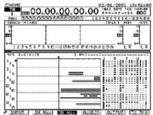
line
| Time (s) | Value | |----------|-------| | 0 | 0 | | 12.3 | 0 | | 12.4 | 0 | | 12.5 | 0 |This takes a few moments, as explained in the next section.
- Turn on your monitor speakers or monitoring system.
What Happens During the VS-2480's Power-Up
When you turn the VS-2480 on, it performs a few important tasks that help ensure its successful operation. It:
- performs some diagnostic routines to make sure everything's working properly.
• scans its SCSI bus to learn what SCSI devices are connected and available for use. - sets up the available effects.
- re-loads the project that was loaded at power-down. (When you turn on the VS-2480 for the first time, this is the "What You Don't Know" demo.) As a project loads, the faders move to their last-saved positions and the project's settings are restored.

SCSI, SCSI bus
Configuring the VS-2480
Setting Up the VGA Monitor, Mouse and Keyboard
You'll want to make sure your mouse, keyboard and VGA monitor are properly set up. All of the settings for these devices are found on the same UTILITY menu pages. To get there:
- Press UTILITY.
- Press PAGE—if necessary—until "SYSTEM" appears above F1.
- Press F1 (SYSTEM).
- Press F2 (Param2).
- Use the ◀, ▶, ▲ and ▼ buttons as necessary to select each setting—a setting's outline darkens when it's selected—and turn the TIME/VALUE dial to choose the desired value.
If you don't have a VGA monitor or keyboard, skip over its parameters.
VGA Monitor Parameters
Parameter: What it sets: Typical setting is:
| VGA OUT Turns the VGA output on or off On | |
| REFRESH RATE Sets the rate at which the monitor redraws it image | Manufacturer's recommended setting |
| H. POSITION Shifts the image left or right 0 | |
| V. POSITION Shifts the image up or down 0 | |


Consult your VGA monitor's documentation to learn its recommended refresh rate. If you select a value the monitor doesn't support, image quality may be poor, and damage to the monitor may result.
The VGA parameters are described in greater detail on Page 361.
Mouse Parameters
Parameter: What it sets: Typical setting is:
| PS/2 MOUSE | Turns the mouse on or off | On |
| POINTER SPEED | Sets how fast the mouse's cursor moves | 3 |
ASCII Keyboard Parameters
Parameter: What it sets: Typical setting is:
| PS/2 KEYBOARD | Turns the keyboard on or off | On |
| KEYBOARD TYPE | Selects the nationality of the ASCII keyboard you’re using | 101/104 (in USA); 106/109 (Japan) |
Setting the VS-2480's Clock
The VS-2480 time-stamps your recordings to make it easier for you to keep track of your work. In order to allow the VS-2480 to do this, you'll need to set its system clock.
- Press UTILITY.
- Press PAGE repeatedly—if necessary—until "DATE" appears above F5.
- Press F5 (DATE). The DATE/TIME screen appears.
-
If the DATE parameter isn't selected, use the ◀, ▶, ▲ and ▼ buttons to select it.
-
If the month isn't already selected, press to select it.
-
Turn the TIME/VALUE dial until the current month is displayed.
-
Press ▶ and turn the TIME/VALUE dial to choose today's date.
-
Press ▶ and turn the TIME/VALUE dial to choose the current year.
-
Press ▶ and turn the TIME/VALUE dial to choose the desired DATE FORMAT setting. Dates can be shown on the display in any of the following styles:
This value: Displays dates as:
mm/dd/yyyy 07/12/2001
dd/mm/yyyy 12/07/2001
yyyy/mm/dd 2001/07/12
- Press ▼ to select the TIME parameter.
- Turn the TIME/VALUE dial to select the current hour.

The VS-2480 uses 24-hour time: Midnight is Hour 00, 1 am is 01, and 1 pm is Hour 13.
- Press ▶ and turn the TIME/VALUE dial to select the minute, and then second.
- Press F5 (SET) to confirm your changes.
- Press F6 (EXIT) to leave the DATE/TIME screen and finish the procedure.
A Few Fundamental Concepts
Selection
Before you can change something in the VS-2480, you must first select it. In the case of physical controls, it's obvious: before you can move a fader, you've got to grab it with your fingers. This rule also applies to items shown on the VS-2480's display. When you select something on the display, you're telling the VS-2480 you want to do something to the thing you've selected. The two most common ways to make a selection are to use the cursor buttons or to click the desired item with your mouse. Once you've made a selection, you can make the desired change using the appropriate tool.
When you select one displayed item and then another, you're moving the "selection cursor."
The VS-2480 shows you what's currently selected. Often, the selected item becomes "highlighted" —its colors are inverted. Text, for example, becomes white with a black background.
When you select a box in which you can enter data or choose a different value, the box's outline becomes darkened.

PROJECT NEW
Name:

Switches
Some settings in the VS-2480 are presented as switches. They're typically shown in either of two ways:
- As a box—when a switch is on, it's darkened. When it's off, it's not.
- As checked items—when a value is checked, it's on. If it's not, it's off.


Parameters and Values
Up until now in this manual, we've been using the word "setting" to describe something you can adjust. The correct term is actually "parameter," the word we'll use from here on (except in a few cases where "setting" is clearer). When you adjust a parameter, what you change is its "value." You can set a parameter with the cursor buttons—see below—and TIME/VALUE dial, or by using your mouse (Page 68).
Tools You'll Use All the Time
The Cursor/ZOOM Buttons
Most of the time, you can navigate to the desired parameter on the display by pressing the ◀, ▶, ▲ and ▼ cursor/ZOOM buttons. When you press any of these buttons, you'll see the selection cursor move in the direction of the arrow button you've pressed.

By holding down SHIFT and pressing the ◀, ▶, ▲ and ▼ buttons, you can zoom in or out on track displays. See Page 42.
If you've connected an ASCII keyboard to the VS-2480, you can often use its arrow keys instead of the ◀, ▶, ▲ or ▼ buttons.
The F Buttons
In all of the VS-2480's operations, the LCD display provides information and visual feedback about what you're doing. Parameters, on/off switches and more appear on the display. Often, boxes appear at the bottom of the display—each of these boxes shows the current function of the F button directly beneath it.
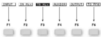
flowchart
graph TD
    INPUT --> F1
    IN Mix --> F2
    TO Mix --> F3
    RUXDIR --> F4
    OUTPUT --> F5
    TG_PFS --> F6
If there's nothing on the display above an F button, it's currently inactive.

You can always use the F1-F6 buttons on a connected ASCII keyboard instead of the F buttons beneath the VS-2480's display if you wish.
When the boxes at the bottom of the screen are small rectangles, the F buttons typically:
• display the parameters associated with an operation.
- execute an operation.
- act as on/off switches.
- change the value of the associated parameter.
- move the selection cursor to a location on the display.
- exit the current screen.
Sometimes the boxes at the bottom of the screen are large and contain icons. When this is the case, you can press the corresponding F button to begin an operation or view a menu of related parameters.

In all cases, the F button label tells you what the button does.
Pages

Often, there are more parameters available than can fit on the display at once. In these cases, the parameters are arranged over several "pages" on the display. In such situations, you see the Page symbol in the lower left-hand corner of the display—the display may also show what look like folder tabs, presenting the available pages as tabbed layers.

Press the PAGE button repeatedly to display each of the available pages.
If you've connected an ASCII keyboard to the VS-2480, you can always press its Tab key instead of the VS-2480's PAGE button.
Param 1, 2, Etc. Screens
In some VS-2480 menus, parameter pages are divided further into sub-pages called "Param1," "Param2," etc. You can select one of these sub-pages by pressing its F button.
The TIME/VALUE Dial

Once you've selected a parameter you want to edit, you can turn the TIME/VALUE dial to change the parameter's value. (The TIME/VALUE dial is the inner part of the large black dial—the outer part is the SHUTTLE ring, described on Page 178.)


When you're adjusting parameter values with the TIME/VALUE dial, hold down SHIFT as you turn the dial to move through the available values by different-sized increments.
You can change your current time location in a project using the TIME/VALUE dial (see Page 126).
The ENTER/YES and EXIT/NO Buttons
Use the ENTER/YES or EXIT/NO buttons to execute or cancel the current operation, or to respond to a question posed on the display.

The ENTER/YES and EXIT NO buttons blink to signify that you can press the:
- ENTER/YES button to finish, or press EXIT/NO to cancel, the current operation.
- ENTER/YES to answer "yes" to a displayed question, or EXIT/NO to reply "no."
The ENTER/YES button also blinks to indicate that you can press it to view additional options. EXIT/NO flashes at times to show you can press it to exit the current screen.
If you prefer, you can always use the Enter key on your keyboard instead of ENTER/YES, or the Esc key instead of EXIT/NO.

The SHIFT Button
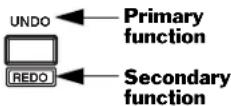
Many of the VS-2480's buttons perform more than one job—these buttons often have an upper label and a lower label that's printed inside an outline box. The un-boxed label shows the button's primary function, the boxed label its secondary use.
To cause a button to perform its secondary job, hold down SHIFT and press the button before letting go SHIFT.
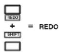
You can set the SHIFT button so that it toggles on and off with each touch to cut down on SHIFT-button presses. See "SHIFT LOCK" on Page 363.

Using a Mouse
The VS-2480 uses a two-button mouse. If we say to "click" the mouse, click the left-hand button. You can click the right-hand button to display various pop-up menus.
Mouse Cursors
The cursor changes to show you what the mouse can do as you move it over different items on the display.
This cursor: Means that the mouse:
| is moving between items on the display. On the Home screen, you can click on a track to select it. | |
| can click on the item beneath the cursor. If it's a switch, you can toggle through its values by repeatedly clicking. If it's an adjustable parameter, you'll see either of the next two cursors after you click. | |
| can raise or lower the parameter's value as you drag the mouse up or down, respectively. | |
| can raise or lower a parameter's value as you drag the mouse right or left, respectively. | |
| can drag the data beneath it during editing operations. | |
| is ready to move whatever's beneath the mouse to a new location. | |
| is ready to copy whatever's beneath the mouse by dragging; this appears when SHIFT is held down during track editing. |

When a parameter's values are presented in a list or in a box, you can simply click the desired value with your mouse without having to select the parameter first.
Pop-Up Menus
When a pop-up menu is available, you can select an item in the menu by dragging the mouse to it—so the item's highlighted—and then click the left mouse button to select it. The following two pop-up menus are available from a number of screens.

Drag to the desired menu item and click.
Display Pop-Up Menu
You can quickly jump to some of the VS-2480's most important screens by clicking on the small rectangle in the upper left-hand corner of many of the VS-2480's screens.
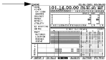
Channel Pop-Up Menu
If you're using a mouse, you can also select a new input, track or FX return channel from any screen on which the currently selected channel's number is displayed as shown here.


To select a new channel:
- Click the channel number. The Channel Pop-Up menu appears.
- Move the cursor to the desired channel and click.
Using an ASCII Keyboard

After you've connect an ASCII keyboard to the PS/2 KEYBOARD jack, and activated it (Page 64), you can use the keyboard to perform various actions.
What You Can Do With an ASCII Keyboard
You can use the keyboard's: To:
Letter and number keys enter names for projects, tracks, scenes, locators, etc.
Space bar start, stop and continue project playback
Arrow keys move the cursor on the VS-2480's display
SHIFT+arrow keys zoom in and out vertically and horizontally
Home display the Home screen
F7 display the EZ Routing VIEW screen
SHIFT+F7 display the EZ Routing P.BAY screen
SHIFT+F8 display Mastering Room screen
Ctrl+S store the current project
Ctrl+Alt+Delete
shut down the VS-2480
And the keyboard's: Acts as the VS-2480's:
F1-F6 F1-F6 buttons
Tab the PAGE button
Enter the ENTER/YES button or left mouse button
Esc the EXIT/NO button
F9 the PROJECT MENU button
F10 the TRACK MENU button
F11 the EFFECT MENU button
F12 the UTILITY MENU button
Using the VGA Info Display
Most of the VS-2480 Info Display's screens are divided into four areas.


The Info Display also provides a date and time readout in its upper right-hand corner.
General Information Strip

This area appears at the top of all of the Info Display's screens. The:
-
ABS/REL indicators—tell whether the Info Display's time counters are showing absolute time or are shifted to correspond to the setting of the SYNC OFFSET TIME parameter in the UTILITY menu.
-
VARI PITCH indicator—shows when VARI PITCH in the UTILITY menu is on.
-
TIME—shows the current location in hours, minutes, seconds, frames, subframes.
-
MEASURE/BEAT/TICK—shows the current time in measures, beats and ticks. (There are 480 ticks in each beat.)
-
MARKER—shows the last marker before the current position of the timeline.
-
A.PUNCH indicator—shows when automatic punching is turned on.
-
EXTSYNC indicator—shows when external synchronization is active.
-
LOOP indicator—shows when looping is turned on.
- AUTOMIX indicator—shows when Automix is turned on.
- REMAIN—shows how much disk space you have left. (You can set the unit of measurement with the REMAIN DISPLAY TYPE parameter in the UTILITY menu.)
- SCENE—shows the number and name of the current scene.
PAN/AUX SEND 1-8 Knob Strip
Currently selected channel group

The VS-2480's PAN/AUX Send 1-8 knobs can perform a variety of functions, as described on Page 139. This strip shows their current settings. At the left of the strip, the currently selected channel group and channel are shown. To the right of the strip are input clipping indicators that show when a channel's input signal level is too loud.
Meters Strip
In certain display modes—see "Selecting Info Displays Manually" below—the meters strip shows the set of meters currently selected on the Home screen.

Bottom Pane
The contents of the Info Display's bottom pane changes from screen to screen.
Controlling What's On the Info Display
As you navigate the VS-2480's LCD display, the Info Display automatically switches between various screens. You can manually switch to a few key screens, and you can lock the display so that it doesn't change as you move around on the VS-2480.
Selecting Info Displays Manually
You can access several key screens from the VS-2480's Home screen.
- Press HOME/DISPLAY.
- Press PAGE until "ID PL" appears above the F1 button.

-
You can press F1 through F5 to view the following screens:
-
ID PL (Info Display Playlist screen)—shows the track playlist in the lower area on the display.
- ID IN (Info Display Input Channels)—shows all 24 input channels in the lower area on the display.
- ID TR (Info Display Track Channels)—shows all 24 track channels in the lower area on the display.
- ID Mlt (Info Display Multiple Parameters)—shows a detailed view of the currently selected group of 16 channel strips (Page 137).
- ID ChV (Info Display Channel View)—shows the CH EDIT parameters for the currently selected input, track or FX return channel.
When the ID PL, ID IN or ID TR screens are in view, the meters strip is visible. You can change what's shown on the left side of the meters strip—the right side always shows the MONITOR and MASTER output levels:
- Press HOME/DISPLAY.
- Press PAGE until INPUT appears above F1.
- Press:
- INPUT—to meter the VS-2480's analog and digital input jacks and connectors.
• IN Mix—to meter input channel levels.
• TR Mix—to meter track channel levels.
- AUXDIR—to meter the AUX and DIR bus levels.
• OUTPUT—to meter the VS-2480's output levels.
Locking the Info Display
You can lock the currently displayed Info Display screen so that it stays in view as you move from screen to screen on the VS-2480 itself.
- Press HOME/DISPLAY.
- Press PAGE until "IDHold" appears above the F6 button.
- Press F6 (IDHold).
- To unlock the display, repeat Steps 1-3.
UNDO and REDO
Undo
The Undo function allows you to reverse—or “undo”—track recording and editing operations. Each project remembers up to 999 of your most recent recording and editing actions and can restore the project to the state it was in before each action.
Each action is assigned a numbered "Undo level." The lower the number of the level, the more recent the action. All undoable actions in a project appear in the Undo list along with the date and time of each action.


When you undo a recording or editing operation, everything you did after the operation originally took place is also undone.
Undo affects track recording and editing operations only—it doesn't undo parameter value changes.

If a project contains data required for undoing actions you're sure you'll never need to undo, you can perform a project optimization to discard the unwanted data and reduce the size of the project and the space it takes up on your hard disk. See Page 100.
Undoing a Track Recording or Editing Operation
- Press UNDO•REDO.
- Locate the desired action in the Undo list.
- Turn the TIME VALUE dial to select the desired Undo level—the selected level has an arrow to its left.
- Press ENTER/YES. The selected action—and all other recording and editing actions that took place after it—is undone.
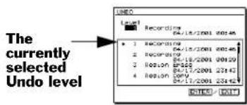

After the Undo operation is complete, the UNDO•REDO button remains lit to indicate that you can cancel the Undo operation by performing a Redo.
You can set the UTILITY menu's UNDO MESSAGE parameter so that when you press UNDO, the VS-2480 instantly reverses the last operation without displaying the Undo list—see Page 364.
Redo
If you change your mind about an action—or series of actions—you've undone, you can perform a "Redo" while the UNDO•REDO button is lit. To do this, hold down SHIFT and press UNDO•REDO. When the Redo dialog appears, press ENTER/YES.

The ability to perform a Redo operation lasts only until you next save the project.
Naming
You can assign names to a wide range of things in the VS-2480, such as:
- projects (Page 99) • tracks (Page 272) • takes (Page 262)
- phrases (Page 261) • effect patches (Page 225) • locators (Page 186)
- markers (Page 190) • scenes (Page 144) • routing templates (Page 296)
The pages in the above list provide details about how to access each item's naming screen. The procedure you'll use is the same no matter what it is you're naming, and all of the naming screens feature an area that looks like this:
![TRACK NAME EDIT [ 1-1:U.T 1- 1 ] Q.T 1- 1 ABCDEFGHIJKLMNOPQRSTUVWXYZ abcdefshijklmnoparstuvvxyz 0123456789!"#$%&' <>*+,-./ :;<=>?@[\]^_^(';)→= HIST BackSP DELETE INSERT OK CANCEL](/content/2026/06/1205688/images/c99ef1f04dfada2dfb5990d41224de8bfca964514e97540291b8a33c9bb4c841.jpg)

The project-naming screen provides some additional elements, including information about the project and an area into which you can enter comments about the project.
Entering a New Name Using the VS-2480 Controls
- Press ◀ to select the first character in the naming box if it isn't already selected.
- Turn the TIME/VALUE dial to select the desired first character—a box appears around the currently selected character in the area below the naming box.
- Press ▶ to select the next character.
- Turn the TIME/VALUE dial to select the second character in the new name.
- Repeat Steps 3 and 4 until you've entered the entire new name.
- When you're done, press F5 (OK).
Entering a New Name from a Keyboard
- Press ◀ to select the first character in the naming box if it isn't already selected.
- Type the desired name.
- Press F5 (OK).
Naming Tools
The F buttons beneath the naming screen provide tools you may want to use as you create a name.
Press: To:
F1 (HIST) recall with each press one of the names you've entered since powering up.
F2 (BackSp) delete the character to the left of the currently selected character.
F3 (DELETE) erase the currently selected character and move all following characters to the left by one position.
F4 (INSERT) add a blank space before the currently selected character, moving all following characters one position to the right.
F5 (OK) assign the currently entered text to the item you're naming.
F6 (CANCEL) leave the naming screen without assigning a new name.
Entering Numbers with the Numeric Keypad
In parameter boxes that contain project time locations, you can enter the desired number using the VS-2480 numeric keypad. To do this:
- Press NUMERICS. It lights—and ENTER/YES and EXIT/NO flash—to indicate that the keypad is active.
- Press ◀ or ▶ to select the part of the number you want to enter.
If you're entering a long string of numbers, select the right-most digit on the display—each number you enter from the keypad pushes the displayed numbers to the left.
You can set the VS-2480 so that numbers are entered from the keypad right-to-left (the default method) or left-to-right. See "NUMERICS TYPE" on Page 364.
- Enter the desired value by pressing the appropriate keys on the keypad.
- When you've finished entering the number, press ENTER/YES.
To enter "-" using the keypad, press "0" twice.


If You're Using DS-90A or DS-50A Monitors
If you're using Roland DS-90A or DS-50A Digital Reference Monitors, you'll need to route the MONITOR bus to the digital output to which you're connecting the monitors. (In the factory demo songs, this has already been taken care of. When you create a new project, however, the MASTER stereo mix, not the stereo MONITOR bus, is routed to the OPTICAL and COAXIAL OUT connectors.)
Setting Up for Roland's DS-90A and DS-50A Digital Monitors
- Press EZ ROUTING•PATCHBAY.
- Press F3 (OUTPUT). The OUTPUT ASSIGN screen appears. On this screen, you can change the signal routed to each of the VS-2480 output jacks and connectors.
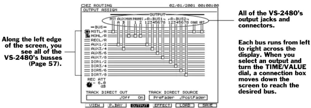
- Press ▶ until the digital output you want to connect to your monitors is selected in the top row—in this screenshot, we've chosen the COAXIAL OUT:

The thick black line—think of it as a virtual cable—shows that the MASTER mix (MASTL/R) is routed to the COAXIAL OUT (COAX).
- Turn the TIME/VALUE dial clockwise so that "cable" connects MONL/R to the selected digital OUT connector—"MONL/R" stands for "MONITOR Left/Right."
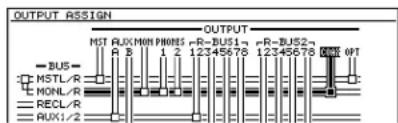
If you prefer, you can drag the output's connection box down to MONL/R using your mouse.
Adjusting Your Listening Level
If you're listening to the VS-2480 through monitor speakers, the MONITOR knob to the left of the display sets your listening level. You'll generally want to keep this at the 0dB position (3 o'clock). Of course, you can always turn the MONITOR knob to raise or lower the listening level as needed—the 0dB position serves as a good starting point. Adjust your DS-90A/DS-50A INPUT LEVEL or monitor-speaker amplifier level settings so that the VS-2480 is producing sound at a desirable level.

If you're using headphones, the setting of the MONITOR knob establishes the basic monitoring level, so set it to its 0dB position. To adjust your headphones' volume, use the PHONES 1 or 2 knob that corresponds to the jack into which you've plugged your headphones. Start with the knob turned all the way counter-clockwise, and slowly turn it clockwise to reach the desired listening level.

If you've connected a speaker system directly to the VS-2480 and would like separate control of your speakers and headphones, route the MASTER outputs to the desired PHONES jack on the EZ ROUTING OUTPUT ASSIGN screen (see Steps 1-3 in "If You're Using DS-90A or DS-50A Monitors" on Page 75). The MONITOR knob will control only the speakers, and each PHONES knob will control the associated jack.

In the factory demos, the MASTER bus is routed to the PHONES jacks, so each PHONES knob independently controls the level produced by its headphone jack.
Playing the Factory Demos
As shipped from the factory, your VS-2480 has two demonstration songs—"demos"—stored as projects on its internal hard drive. When you power up the VS-2480, the "What You Don't Know" project is loaded into the VS-2480, all of its settings are restored, and its track channel faders move to their last-saved positions.

If you'd like to make changes to a demo project and save your changes, make a copy of the project (Page 101) to work with. The copies loaded onto your hard drive at the factory are write-protected (Page 99) and are therefore not editable.
"What You Don't Know"
This section presumes you've just powered up your VS-2480 and the factory demo project "What You Don't Know" is loaded. If this isn't the case, load "What You Don't Know" —see "Loading a Project" on Page 95 to learn how to load a project. (For demo details, see the track sheets included in the VS-2480 box.)
Bring Down the MASTER Fader
To make sure the demo isn't too loud, bring the MASTER fader all the way down before you play the demo.
The MASTER fader controls the level of the MASTER mix bus that's routed to the MONITOR bus (see "What's a Bus?" on Page 57). Since the MONITOR bus is supplying audio to the MONITOR and PHONES jacks—and to the digital output you're using for your DS-90Aor DS-50A Digital Reference Monitors—moving the MASTER fader has the effect of adjusting your listening level.
Starting Playback of the Demo
- Press PLAY to begin playback.
- Slowly bring up the MASTER fader to set the MASTER mix to a comfortable listening level.

If the demo finishes playing before you're done reading the following sections, press ZERO to restart it.
A Quick Look at What's on the Display
- Press HOME•DISPLAY.
- Press PAGE until "INPUT" appears on the display above F1. The display should look something like this:
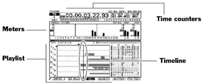
- If it doesn't, hold down SHIFT and press HOME•DISPLAY repeatedly until it does. You can also change the magnification of the playlist by holding down SHIFT and pressing ◀, ▶, ▲ and/or ▼.
You're now looking at the Home screen. This screen is so important that an entire chapter—Chapter 8, starting on Page 119—is devoted to it. For now, we'll just point out a few items of interest. They're labeled in the illustration above.
- Time counters—The time counters show your current location in the project. You can move to a new location by dialing in a new time in the counters, as described on Page 126.
- Meters—The meters show you important level information during recording and playback. If TR Mix above F3 isn't highlighted, press F3 (TR Mix). The meters are now showing you the level of each of the project's tracks.
- Playlist—The playlist shows the data on all of the project's tracks. Each chunk of data you see is called a “phrase,” and is shown as a rectangle. As the project plays, the data moves from right to left. (We’ll explain tracks, phrases and more on Page 86.)
- Timeline—The timeline is a visual representation of the time location shown in the counters. It shows you where in the project you are right now. You can think of it as the “now line” if you prefer. When data in the playlist crosses the timeline, you hear it.
Stopping and Starting Playback
- To stop listening to the demo before it ends, press STOP.
- To resume playback from the spot at which you stopped, press PLAY.
- To play the demo again from the top, press ZERO, and then PLAY.
- You can turn the SHUTTLE ring on the outside of the TIME/VALUE dial to fast-forward and rewind.
Navigating the Demo Using Locators
You can store up to 100 specific time locations in each project as "locators." By recalling a locator, you can instantly jump to its location in the project.
"What You Don't Know" contains 10 locators, all stored in Locator Bank 0—there are ten locator banks, numbered 0-9.
Here's where the locators in Bank 0 take you:
Locator Number: Takes you to: At hour:minute:second:frame:subframe:
00 Verse 1 00:00:10:15:00
01 Turnaround 1 00:00:37:12:11
02 Chorus 1 00:00:48:05:78
03 Turnaround 2 00:01:33:15:36
04 Chorus 2 00:01:45:06:02
05 Interlude 00:02:13:06:79
06 vocal lick before the solo 00:02:32:08:94
07 just before the solo 00:02:35:02:94
08 end of the solo 00:03:01:11:63
09 Tag 00:04:11:18:00
You can recall locators when the project is playing or stopped—we'll recall them when the project isn't playing so you can see how they help you move through a project:
- Press STOP to stop playback.
- Press ZERO to return to the beginning—Time Zero—of the project.
- If LOCATOR•BANK isn't lit, press it so that it lights. Since Locator Bank 0 is already selected, we only need to press the desired locator's second digit.
- Press 0—the VS-2480 takes you to Locator 00, the top of the first verse.
- Press 5—you're now at the start of the breakdown in the middle of the project.
Locators are discussed in detail in "Locators" on Page 185.
Adjusting Track Levels
The VS-2480's 16 physical channel strips (Page 33) can control any of the VS-2480's input, track, Aux master or FX return channels. See Chapter 10.
- If TR 1-16 isn't already lit, press it. Once it's lit, the channel strips control the sound of Tracks 1-16.
- Press ZERO to return to the beginning, and then press PLAY to begin playback.
- Slide the channel strip faders up and down to hear how they change the levels of the first 16 tracks in "What You Don't Know."
- Press TR 17-24/FX RTN to assign the channel strips to the control of Tracks 17-24 and the eight FX returns.
- Explore the level changes you can make to Tracks 17-24 and the effects.
Watching Automix in Action
Automix allows the VS-2480 to memorize and play back mix-related settings, including any changes you make to those settings as the project plays.
"What You Don't Know" contains Automix data that adjusts various track channel levels throughout the course of the song. Since the VS-2480 has motorized faders, you can literally watch some of these changes taking place.
- Press AUTOMIX so that it lights—Automix is now turned on.
- Press TR 1-16 so the 16 channel strips are controlling Tracks 1-16.
IN 1-16

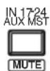
- Press 1 on the numeric keypad to jump to Locator 01 at the start of the first turnaround. The first four faders—the bass drum, snare, hi-hat and floor tom—move downward since the drums don't play in this part of the project.
- Press PLAY to begin playback.
- Watch how the drum faders move up in time for the drums' entry in the chorus.
- Press ZERO and then hit PLAY to watch Automix at work.
- When you're done, press ZERO and then AUTOMIX to turn it off.
See Chapter 26 to learn about Automix.
Playing the Phrase Pads
You can press a channel strip's TRACK STATUS/PHRASE PAD button—we'll call it a "PHRASE PAD" button for the rest of this section—to play a phrase located on the corresponding track. This feature can be turned on or off for each track in a project. In "You Don't Know," you can play phrases on several tracks.
- Press PHRASE PAD PLAY•PHRASE SEQ so that it lights green.
- Press TR 1-16 so the channel strips control Track Channels 1-16. The PHRASE PAD buttons for Tracks 4-10 are lit in amber to show that they're set to play phrases.
- Press the PHRASE PAD button for Track Channel 9—the first Taos drum phrase sounds.

In "What You Don't Know," Tracks 9 and 10 are linked (Page 152). When you play a linked channel's phrase pad, both tracks play. In this case, the stereo Taos drum on Tracks 9 and 10 plays. Tracks 5 and 6, and Tracks 7 and 8 are also linked in this project.
- Play a rhythm on Track Channel 9's PHRASE PAD button.
- Do the same with Track Channel 8 to play a phrase on Tracks 7 and 8.
- Try out the phrases on Track 4 and Tracks 5/6. The play audio from overhead drum mics that've captured the room sound from the bass drum, snare and hi-hat.
To learn more about the phrase pads, see Chapter 21, "Using the Phrase Pads."
Recalling Scenes
The VS-2480 can memorize up to 100 mix setups as "scenes." Scenes allow you to:
- store and recall multiple versions of a mix.
- store and recall different versions of a project with different V-Tracks (Page 90).
"What You Don't Know" contains some scenes that show off the way scenes work.
-
Press SCENE•BANK so it lights.
Scenes—like locators—are stored in banks of ten scenes each, numbered from 0-9. Since Scene Bank 0 is already selected, we only need to enter each desired scene's second digit for the scenes in "What You Don't Know." -
Press 1 on the keypad. Scene 01—Default Mix—loads the settings it contains.

The name of the current scene appears in the top right area of a connected Info Display.
- Play "What You Don't Know" to hear how it sounds in Scene 01.
- Press STOP when you're done and keep your eyes on the display.
You can recall scenes only while a project isn't playing, so press STOP before attempting to recall a scene.

- Press SCENE again, and then 2 on the keypad to recall Scene 02—AcIntro Dflt. The display changes to show that this scene uses different V-Tracks than Scene 01.
- Press ZERO and then PLAY to hear what's been added to the project's introduction.
- Try out the other scenes in "What You Don't Know."
To learn about storing scenes, recalling them and more, see "Scenes" on Page 144.
"Don't Stop"
Your hard drive also contains a second demo project, "Don't Stop," by Teddy Riley. To learn how to load this demo project, see "Loading a Project" on Page 95.
Turning Off the VS-2480

It's important the you don't simply flip the VS-2480's POWER switch to turn it off—always use the procedure below to prevent damage to your data.

If you'd like to restart the VS-2480—perhaps while troubleshooting a problem—use the procedure below as well.
Turning Off the VS-2480
- Hold down SHIFT, and press STOP•SHUT/EJECT. The following dialog appears:

- If you wish to turn off or restart the VS-2480, press ENTER/YES. If not, press EXIT/NO to cancel the operation. If you press ENTER/YES, a dialog like this one appears:

Loop Effects
With a loop effect, you combine two different versions of the signal: the original dry signal and an effected, wet version. This is accomplished in two stages. - You send a copy of the signal into the effect. - You return the output of the effect—the wet version of the signal—to a mixer channel, and combine this channel's signal with the original signal. flowchart
graph TD
    A["Dry signal"] --> B["Copy of dry signal"]
    B --> C["Effect"]
    D["Dry signal"] --> E["Wet signal"]
    E --> C
About the Terms "Send" and "Return"
"Send" and "return" are used in mixing as both verbs and nouns. This can be confusing to beginners, so let's be clear about what we mean. When we use: As a verb, it describes the act of: As a noun, it refers to:| Send directing a signal into an effect, as in “Send Track Channel 1 into Effect 1.” | the device we use to carry the copy into the effect, as in “Adjust the send.” Also, the copy itself, as in “The send is too loud.” |
| Return routing the effect’s output into a channel, as in, “Return Effect 1 to FX Return Channel 1.” | the channel into which the effect’s output is routed, as in “Adjust the return.” |
Aux Sends
In the VS-2480, each of the eight Aux send busses provides a pathway into one of the eight internal effects. By default, Aux 1 carries signals into Effect 1, Aux 2 to Effect 2, and so on. When you want to send an input, track or even an FX return channel's signal to an internal effect, you send it to the corresponding Aux bus—you can set how much of the signal you want to send to the effect by setting the AUX send level on its CH EDIT screen or by using the PAN/AUX SEND 1-8 knobs (Page 139).Pre-Fader and Post-Fader Sends
The VS-2480 allows you to send a signal to an Aux bus from either of two places as the signal makes its way through a channel. You can send it: - pre-fader—to send the signal to the Aux bus before the signal reaches its channel fader. The Aux send level isn't affected by changes you make to the fader's position—it stays the same even if the level of the signal itself changes. This can be handy, for example, if you're using an Aux bus to create a headphone mix for performers, and don't want them to be bothered by changes you make to the channel's output level. It can also be useful if you're sending a signal to an effect and want its effect level to remain constant as the level of the signal itself changes. - post-fader—to send the signal to the Aux bus after its fader. Changes you make to the signal's level using its fader affect the amount of the signal sent to the Aux bus. As the fader goes up, the Aux send level goes up, and vice versa. This can be especially useful when you're using the Aux bus to add an effect to the signal—the relationship between the signal level and effect level stays the same as you change the signal's level. You'll usually want to use a post-fader send for effects. Each Aux bus can be configured to accept either pre-fader or post-fader signals from the input, track and FX return channels, as described on Page 207.When To Use Loop Effects
You'll use loop effects any time you want to add an effect to a signal so that both the signal and the effect are heard. The most frequent use of loop effects is with reverbs and delays, the two most frequently used effects there are.Master Effects
The VS-2480 allows you to apply an effect to your entire mix at once. You can do this by inserting the effect into the main MASTER mix's signal path. While you can do this at any time, this capability is particularly important when creating final stereo mastering tracks in preparation for burning an audio CD. The VS-2480's Mastering Tool Kit (MTK) effects are specially designed for this purpose and provide everything you need to add the final touches to your recordings.  Mastering tracksExternal Effects
While the VS-2480 provides a wide range of effects, you may wish to send a signal out of the VS-2480 and into an external effect processor. You'll use the processor's effect as a loop effect, by: - sending the signal to an Aux bus - routing the Aux bus to one of the VS-2480's outputs - connecting the output to the input of the external device - processing the signal inside the external device - connecting the device's output to one of the VS-2480's inputs to return the wet signal to the VS-2480. External effect processor  VS-2480 We'll describe this procedure in more detail on Page 215.  Even though an external effect is always a loop effect, you can simulate an insert effect by using only the external processor's return, and none of the original dry signal.Getting the Most From Your Effect Processors
It's important to be strategic about how you employ your effects so that you'll have the effects you need at each step along the way as you record and mix your project. Even engineers in the best-equipped studios in the world may find that they wish they had one more effect processor available from time to time. The simple truth is that while an effect processor's creating a particular effect, it's not available for any other use. Here's an example. If you've got a single VS8F-2 in your VS-2480 and are already using Effect 1 and 2, you don't have any other internal effect processors available for a third effect. (This is why we recommend installing as many VS8F-2's in your VS-2480 as possible.)Consider Recording Your Effects As You Go
The solution is planning. Try to work out in advance the effects you'll need for all of the elements in your project. This will allow you to budget your effect-processing power. One of the main tricks you can use to be sure you've got all the effects you need is to apply a signal's effect as you record the signal—the resulting track contains both the signal and its effect. This is called "printing" the effect. The benefit of recording your effects as you go is that it frees up the effect processor for later use. This method isn't without risk, however: Once you've recorded an effect onto a track along with a signal, the effect can't be altered or removed. It can also be difficult to anticipate how a signal and its effect will sound when all other project elements have been recorded and are in place. If you've got spare tracks, you can hedge your bets by recording the signal on one track, its effect on another, and then combining them later into a single track—or pair of tracks if you're using a stereo effect—once you're sure you like what you've got. Even so, printing effects with your tracks can be a real lifesaver in a project that needs lots of effects. Printing effects can also make a mix easier, since the printed effects will have already been dealt with, freeing you up to concentrate on other details during the often-complex mixing process.6—Understanding the Hard Disk Recorder
This chapter describes the fundamentals of hard disk recording in the VS-2480. If you're new to hard disk recording, you'll find all the basics here. We'll explain: • what a hard disk drive is. • how a VS-2480 hard drive organizes data. - how a hard drive must be prepared for use by the VS-2480. • how the VS-2480 records audio on a hard drive. - how the VS-2480 plays back audio recorded on a hard drive. • non-destructive, pointer-based editing. • what a VS-2480 phrase is. • what a VS-2480V-Track is. • what a VS-2480 track is. • what a VS-2480 region is. Even experienced users should read about VS-2480 tracks and their contents: takes, V-Tracks, phrases and regions. You'll need to understand what each of these is to fully master the VS-2480 editing capabilities. See Page 89.VS-2480 Hard Disk Drives
What's a Hard Drive?
 A hard drive is a hardware mechanism that contains a rigid platter—that's why it's called a "hard" drive—on which data is stored. A hard drive may also be referred to as a "disk drive." In the VS-2480, a hard drive stores all of your recordings and project settings. It's a great way to store and quickly retrieve data, and provides for some amazing features, as we'll see. Your VS-2480 shipped from the Roland factory with an 30GB (gigabyte) IDE hard drive installed. This provides lots of space for your projects. In addition, the VS-2480 offers a 25-pin SCSI connector to which you can connect a Zip drive or other compatible SCSI device for backup and to provide additional storage space for project copies. You can also attach a Roland-approved CD-RW drive to the rear-panel SCSI connector. We strongly recommend purchasing a Roland VS-CDRII or CD-RACK for your VS-2480, since either drive allows you to back up your data on inexpensive media and to create your own audio CDs and CD-production masters. CD-RW operations are described in Chapter 27.    Back up, recover The VS-2480 requires an internal hard drive for project recording and playback. If you'd like to replace the original drive with a second drive or a larger one, you can turn off the VS-2480 and swap drives. You'll need an HPD35-K20 mounting kit for the new drive, purchased separately. You can use the kit with an ATA100 3.5" hard drive that has an access time of 10ms or less—for a list of approved drives, see the Roland US Website. You can't power up and use the VS-2480 without an internal hard drive installed.How a VS-2480 Hard Drive Organizes Data
A VS-2480 hard drive divides up its total disk space into sections called “partitions.” Partitions help keep project data together on the hard drive. Each partition acts like a separate virtual drive—it even looks that way on the VS-2480’s screens. Your 30GB VS-2480 internal hard drive was divided into three approximately 10 GB partitions at the factory. These partitions are labeled IDE:0, IDE:1 and IDE:2.  Internal hard drive  When we refer to a “drive” in the rest of the VS-2480, we’ll be referring to a partition. This reflects that way the VS-2480’s software views partitions, and will make disk- and drive-related operations easier to explain and understand. When we need to refer to an entire hard disk mechanism, we’ll call the mechanism a “hard drive.”Preparing a Hard Drive for Use
Before you can use a new internal hard drive with the VS-2480, it must be prepared for use with the VS-2480. The hard drive must be erased, formatted and divided into partitions using the FmtDrv (for "Format Drive") command described on Page 113.  The internal hard drive that came with your VS-2480 was formatted and partitioned before the demo songs were installed at the factory. It's ready to be used as is.Using Other V-Studio Drives
Hard drives formatted for other V-Studios are not compatible with the VS-2480, and a hard drive set up for the VS-2480 can't be used with other V-Studios.How Audio Is Recorded on a VS-2480 Hard Drive
Each time you record audio in the VS-2480, the audio is stored as a disk file comprised of digital data. This file is called a "take." It includes your audio and a time-stamp of the date and time at which the recording took place. Until you perform a project optimization (Page 100), the VS-2480 holds on to all of the takes you've recorded in a project. Even when you re-record a performance—"recording over" your first attempt—the original take actually remains on your hard drive and is still available to you should you want it. And when you edit a recording on the VS-2480, you don't actually edit the take itself, thanks to non-destructive, pointer-based editing, which we'll discuss shortly.How Recordings Are Played Back
Random Access
When your VS-2480 plays back your music from a hard drive, it uses something called “random access” playback. The phrase “random access” has its roots in computer programming, but what it means to you is this: The recorder can instantly play any audio in a project located anywhere on its hard disk. Random access playback produces a couple of very important benefits: - You never have to wait for the recorder to rewind or fast-forward to a location in a project. The VS-2480 gets where it needs to in a heartbeat. - The VS-2480 can employ pointer-based playback and editing.What's Pointer-Based Playback?
When you play a recording, the VS-2480 uses a set of "pointers" to identify the audio you want to play. Each pointer is simply a chunk of information about the audio. Among other things, pointers allow the VS-2480 to play parts of a take, rather than having to play the entire disk file from beginning to end. A simple set of pointers would include information such as: - the identity of the take that contains the desired audio - the time location within the take at which playback is to begin - the time location within the take at which playback is to endPhrases
A set of pointers is called a "phrase." Every time you make a new recording—or punch in and out—the VS-2480 automatically creates a new phrase to play the new audio. Each phrase appears in the Home screen's playlist (Page 122) as rectangle.  Each phrase is a rectangular box. This illustration shows a string of three phrases. Phrases are also created in other ways: - Any time you re-record a portion of a track—typically by punching (Page 191)—the new recording appears on the track as a phrase. - You can create a new phrase that plays a currently unused take.  You can perform various editing operations on phrases, and edit regions of audio within phrases, as we'll discuss later in this chapter, on Page 90.Virtual Tracks, or "V-Tracks"
As you record audio, punch in and out and edit it, you create a string of phrases positioned one after the other in the order in which they'll play back. This string of phrases is called a "Virtual Track," or "V-Track" for short.  From here on in the VS-2480 Owner's Manual, we'll refer to a string of phrases by its short name: "V-Track." Of course, if you've made a recording but haven't done any punching or editing, the V-Track that plays it will consist of just the one phrase that plays the recording's take.Non-Destructive, Pointer-Based Editing
Pointer-Based Editing
When you edit audio on the VS-2480, what you're actually doing is editing a phrase, the set of pointers that instruct the VS-2480 how to play the audio. You're not actually changing the take stored on your hard disk at all—you're only editing its pointers. This type of editing is called “non-destructive editing” because it does no harm to the take itself. It doesn't alter the take at all.  A few editing operations change audio by copying it and altering the copy—even so, the original take remains unaffected, and the pointers simply point to the copied audio. This illustration shows how erasing unwanted audio from a recording affects its pointers. The dark portion of the take is the part that you hear during playback. Before editing: After editing: flowchart
graph LR
    A["Start playback"] --> B["Stress"]
    B --> C["Stop playback"]
    D["Vocal 11. Name of lake"] --> E["1 minute 2 restates 3 restates 4 reduced 5 restates"]
flowchart
graph LR
    A["Start playback"] --> B["Throat-clearing"]
    B --> C["Talking"]
    C --> D["Stop playback"]
    D --> E["Vocal 11. Name of take"]
flowchart
graph LR
    A["1. Take"] --> B["Vocal 1"]
    B --> C["Verse 1"]
    C --> D["Verse 2"]
    D --> E["Chorus 1"]
    E --> F["Verse 3"]
    F --> G["Chorus 2"]
    G --> H["2. Play 3. Stop"]
flowchart
graph LR
    A["2. Play 3: Stop"] --> B["Verse 1"]
    A --> C["Verse 2"]
    A --> D["Chorus 1"]
    A --> E["Verse 3"]
    A --> F["Chorus 2"]
    B --> G["Vocal 2"]
    C --> G
    D --> G
    E --> G
    F --> G
flowchart
graph TD
    A["1. Take"] --> B["Verse 1"]
    B --> C["Vocal 1"]
    D["2. Play"] --> E["Verse 1"]
    E --> F["Vocal 1"]
    G["3. Stop"] --> H["Verse 2"]
    H --> I["Vocal 2"]
    J["4. Take 7. Take"] --> K["Chorus 1"]
    K --> L["Vocal 2"]
    M["5. Play"] --> N["Verse 3"]
    N --> O["Vocal 1"]
    P["6. Stop"] --> Q["Chorus 2"]
    Q --> R["Vocal 1"]
    S["8. Play"] --> T["Chorus 3"]
    T --> U["Vocal 1"]
    V["9. Stop"] --> W["Chorus 2"]
The Advantage of Non-Destructive Editing
Non-destructive editing allows you to undo any edits you perform because all of your original hard disk recordings—your takes—remain safe and sound on your hard disk no matter how many edits you perform on the phrases that play them. It's only their pointers that have been edited. This provides a tremendous amount of creative freedom since you can feel free to explore any creative editing possibility without worrying that you won't be able to get back to where you started.  If you're sure you no longer need your discarded data, you can clear it from your hard drive to gain disk space by performing a project optimization, described on Page 100.What Is a VS-2480 Track?
The VS-2480's 24 tracks resemble the tracks of a traditional multitrack recorder, so its basic operation feels familiar and comfortable to anyone who's used a multitrack recorder. In fact, VS-2480 tracks are something a bit different, something that provides an incredible amount of recording power. If... - a recording is stored on your hard drive as a disk file called a "take," and - the sets of pointers that tell the VS-2480 how to play a take are called "phrases," and - a group of phrases strung together for playback is called a "V-Track" ...then what's a track? In the VS-2480, a track is a collection of 16 V-Tracks, anyone of which can be selected at any given time. When a V-Track is selected, you can record on it or play it back. Each track's 16 V-Tracks can contain anything you want. They can play the same take (or takes) in different ways or they can each contain completely different things altogether. Related recordings on all of the track's V-Tracks  Assorted recordings on the track's V-Tracks  You can select which of its 16 V-Tracks each track will play at any given time. We'll describe how to do this on Page 151.  When you record or play a V-Track, the settings of the corresponding track channel determine what it sounds like. Track 1's currently selected V-Track is heard through Track Channel 1, Track 2's V-Track through Track Channel 2, and so on. Track channels are discussed in Chapters 10, 11 and 14.The Power of V-Tracks
Although the VS-2480 is a 24-track studio, in a very real sense it's way more than that. Since each of its 24 tracks can play any of 16 V-Tracks, a project can actually hold as many as 384 recordings from which you can choose 24 for playback at any given time. flowchart
graph TD
    subgraph Track 1
        A["V1"] --> B["V9"]
        C["V2"] --> D["V10"]
        E["V3"] --> F["V11"]
        G["V4"] --> H["V12"]
        I["V5"] --> J["V13"]
        K["V6"] --> L["V14"]
        M["V7"] --> N["V15"]
        O["V8"] --> P["V16"]
    end
    subgraph Track 2
        Q["V1"] --> R["V9"]
        S["V2"] --> T["V10"]
        U["V3"] --> V["V11"]
        W["V4"] --> X["V12"]
        Y["V5"] --> Z["V13"]
        AA["V6"] --> AB["V14"]
        AC["V7"] --> AD["V15"]
        AE["V8"] --> AF["V16"]
    end
    subgraph Track 3
        AG["V1"] --> AH["V9"]
        AI["V2"] --> AJ["V10"]
        AK["V3"] --> AL["V11"]
        AM["V4"] --> AN["V12"]
        AO["V5"] --> AP["V13"]
        AQ["V6"] --> AR["V14"]
        AS["V7"] --> AT["V15"]
        AU["V8"] --> AV["V16"]
    end
    subgraph Track 4
        AW["V1"] --> AX["V9"]
        AY["V2"] --> AZ["V10"]
        BA["V3"] --> BB["V11"]
        BC["V4"] --> BD["V12"]
        BE["V5"] --> BF["V13"]
        BG["V6"] --> BH["V14"]
        BI["V7"] --> BJ["V15"]
        BK["V8"] --> BL["V16"]
    end
    subgraph Track 5
        BM["V1"] --> BN["V9"]
        BO["VO"] --> BP["VO"]
        BQ["VA"] --> BR["VA"]
    end
    subgraph Track 6
        BS["VO"] --> BT["VA"]
        BU["VA"] --> BV["VA"]
    end
    subgraph Track 7
        BW["VO"] --> BX["VA"]
        BY["VA"] --> BZ["VA"]
    end
    subgraph Track 8
        BZ["VO"] --> CA["VA"]
        CB["VA"] --> DA["VA"]
    end
    subgraph Track 9
        CE["VO"] --> CF["VA"]
        GD["VA"] --> DH["VA"]
    end
    subgraph Track 10
        CE["VO"] --> ID["VA"]
        DJ["VA"] --> DK["VA"]
    end
    subgraph Track 11
        DE["VO"] --> DF["VA"]
        DG["VA"] --> DH["VA"]
    end
    subgraph Track 12
        DE["VO"] --> DI["VA"]
    end
Track Editing Basics
 During editing operations, the word "track" serves as a shorthand for the currently selected V-Track. When we say we're editing a track, what we literally mean is that we're editing the audio on the track's currently selected V-Track. The following sections provide just a brief introduction to the editing of tracks in the VS-2480. We'll discuss it in detail beginning in Chapter 18, which starts on Page 235. There are two basic ways you can edit the contents of a track: - You can work with phrases (Page 87). - You can work on a specific time "region" within a track.About Editing Phrases
Phrase editing is the quickest way to work with a track's audio, since it works with predefined chunks of the track. You can perform a range of operations on a phrase—these are detailed in Chapter 19. You may also find it handy to manually divide the phrases on a V-Track into new convenient, easy-to-work-with chunks. Though this can take a little time, it can save you a lot of time later on in the editing process: - If you're working on a song, and think you'll be moving a track's sections around, you can turn each section into a phrase. This'll let you simply grab the desired phrase when it's time to assemble the track. - If you're using sound effects, you can turn each one into a separate phrase, making the positioning of your elements quick and easy.  The phrase DIVIDE operation can automatically separate your audio into separate phrases, as described on Page 260.  On the VS-2480, you can also play phrases using the TRACK STATUS/PHRASE PAD buttons.About Editing Regions
A region is a selected time range within a track. You define the region you want to edit by placing two "edit points": - IN—The position of the IN marker determines the beginning of the section you want to edit. This location is called the "IN point." - OUT—The position of the OUT marker determines the end of the section you want to edit. This location is called the “OUT point.” The region is the portion of the track that occurs after the IN point and before the OUT point. It can contain data from one or more phrases, and can also contain silence.   Chapter 18 describes how to set IN and OUT points for track editing, as well as two other very important editing points, FROM and TO. See Page 236. Chapter 20, beginning on Page 263, describes region editing operations.7—Project and Drive Operations
This chapter describes the various project- and hard drive-related activities you can perform from the VS-2480's PROJECT menu screens. Most everything that has to do with an entire project can be found on this menu.  You can quickly save the latest changes you've made to the currently loaded project by holding down SHIFT and pressing ZERO•STORE. We recommend you do this often.Navigating the PROJECT Menu Screens
1. Press PROJECT in the MENU area of the VS-2480's top panel.  2. The VS-2480 scans your drives. When it's done, the first PROJECT menu screen appears.  To perform a project- or hard drive-related operation, press the operation's F button, shown on a tabbed layer at the bottom of the screen.   If you're looking for an operation whose F button is currently hidden, press PAGE repeatedly until its F button appears.Working with the PROJECT LIST
You can scroll through the items in the project list by pressing ▼ or ▲.  As noted in "How a VS-2480 Hard Drive Organizes Data" on Page 86, each hard drive partition is called a "drive." The project list shows all your available drives. Your internal drives are labeled as "IDE:(partition number)." As shipped from the factory, these partitions are IDE:0, IDE:1 and IDE:2. Each additional drive—including a connected Roland-approved CD-R/RW drive or a Zip drive—is identified by its SCSI ID number.  To learn how to connect a CD-R/RW drive or a Zip drive to the VS-2480, see Page 381. If you encounter error messages when working with a CD-R/RW drive or a Zip drive, check Page 353 or the VS-2480 Appendices to learn what the messages mean. In the project list, you can also see all of the projects on the currently selected drive. The VS-2480 provides information about each project.   We'll discuss write-protection, project sample rates and recording modes later on in this chapter.Selecting an Item in the Project List
To select a project or drive shown in the project list: 1. Press ▼ or ▲ or turn the TIME/VALUE dial until the desired item is outlined.  When an item is outlined and has an arrow pointing to it from the right, it's selected.To Display the Projects on a Drive
1. Select the drive. When a drive is selected, the LIST button appears in the screen's lower-right-hand corner. 2. Press LIST—the VS-2480 displays a list of the projects on the drive.   To view the contents of an audio CD, see "The CD Player Feature" on Page 353.About "Store Current?" Messages
During the course of most PROJECT menu operations, the VS-2480 asks you:  The VS-2480 displays this message when an operation needs to temporarily borrow the part of the VS-2480's memory that holds the currently loaded project—after the operation is complete, the VS-2480 re-loads the project from your hard drive. If you've made any changes to the project since you last stored it, press ENTER/YES in response to this message to ensure that those changes aren't lost.  If a project is write-protected (Page 99), this message doesn't appear, since the project is locked to prevent the making of any changes to it.Project Operations
About F6 (MARK)
Before you can perform some of the project operations, you have to target the project on which you want to perform the operation. You do this by marking the project.  PROJECT menu F6 (MARK)Marking a Project
1. Press ▼ or ▲ or turn the TIME/VALUE dial to select the project. 2. Press F6 (MARK) to place a checkmark to the left of the project's name, thus targeting it.  F6 (MARK) is available only when a project, not a drive, is selected.SELECT
Press SELECT to load the project that's currently selected in the project list. When it's loaded, it replaces the project that's currently stored in the VS-2480's onboard memory. You can play, record, edit and mix a project only while it's loaded into the VS-2480.  PROJECT menu F1 (SELECT)  The SELECT button doesn't look quite like any other VS-2480 menu button, and it acts differently, too. It's the only button that performs its action as soon as you press it. All of the other buttons merely display the corresponding operation's screens. To load a project from another drive, select the drive and press F6 (LIST), as described in "To Display the Projects on a Drive" on Page 94.Loading a Project
1. Press PROJECT. 2. If "SELECT" isn't visible above F1, press PAGE until it is. 3. In the project list, select the project you want to load. 4. Press F1 (SELECT). The VS-2480 displays:  5. Press ENTER/YES to load the selected project, or EXIT/NO to cancel the operation. If you pressed ENTER/YES, the VS-2480 asks:   If the currently loaded project is write-protected (Page 99), the VS-2480 loads the new project without displaying this question. 6. Press ENTER/YES to store your latest changes to the currently loaded project before loading the new one, or EXIT/NO to skip re-saving it. The VS-2480 loads the selected project into its memory.NEW
When you create a new project, you make two important choices that determine both the nature of the project and what you can do with its audio. While these choices are a product of the VS-2480's great flexibility, they can't be changed once the project's been created, and so they must be made carefully. Before we go through the steps involved in creating a new project, let's discuss these decisions so you'll know what to do when you encounter them during project creation.Sample Rate
All digital recorders record audio by creating a numerical representation of it at a particular moment in time—this numerical representation is called a “sample.” By creating samples many thousands of times per second—and playing them back just as quickly—the illusion is created of a single stream of continuous audio. In fact, what you’re hearing is really a series of separate samples. Since audio is constantly changing, the more samples a recording device makes per second, the greater its chances are of faithfully capturing and reproducing its sound. The number of times per second that a digital recorder samples audio is called its "sample rate." The VS-2480 can record audio at a variety of sample rates. This sample rate: Creates this many samples per second: 32k (kiloHertz) 32,000 44.1kHz 44,100 48kHz 48,000 64kHz 64,000 88.2kHz 88,200 96kHz 96,000  Sample rates are displayed in kiloHertz, or thousands of cycles/samples. On the VS-2480's project NEW screen, "kHz" is abbreviated as "k." You might think you'd always use the highest sample rate, but it's not that simple. Higher sample rates use up disk space faster, and there's an even more serious issue: \- Audio CDs can only play audio recorded at 44.1k. If you've connected a Roland-approved CD-R/RW drive to your VS-2480 and plan to write your project onto an audio CD, use the 44.1k sample rate. (Chapter 27 describes creating audio CDs.)  While you can export non-44.1k audio from the VS-2480 via R-BUS or as .WAV files (Page 356) for processing and eventual return to the VS-2480 for CD-burning, sample rate conversion generally reduces a sound's quality. It's smarter to record your audio at 44.1k in the first place if you plan to deliver it to listeners on an audio CD. The other available sample rates are provided for special needs. Recording at 96k is growing in popularity for the extra quality it promises, but so far, only DVDs can utilize 96k audio—if you're doing a project for DVD, 96k recording is a consideration. The 48k sample rate can be helpful if you're digitally importing 48k-recorded tracks from an external digital device.  Some effect patches are not available in projects that use a 64k-or-higher sample rate.Recording Mode
The VS-2480 provides eight “recording modes” from which to choose. A project’s recording mode configures the VS-2480’s hard disk recorder at the desired balance between a project’s audio quality, how many tracks the project contains, and the amount of disk space its audio consumes. Unless you have a reason to do otherwise, use the 24-track, 24-bit MTP recording mode. The VS-2480 Owner's Manual assumes that your projects use this mode, except as noted. Description of Each Recording Mode Recording mode: Description: M24 (Mastering 24-bit) Audio is recorded as linear 24-bit data. MTP (Multi Track Pro) This is the VS-2480's default 24-bit recording mode. CDR (CD-R Writing) Audio is recorded as 16-bit linear data in a CD disk-image file format ready for burning to an audio CD (Page 340)—great for compiling mastering tracks for an album's worth of songs. M16 (Mastering 16-bit) Audio is recorded as 16-bit linear data similar to that produced by a CD player or DAT recorder. MT1 (Multi Track 1) This recording mode offers twice the recording time of M16 while preserving its sound quality. MT2 (Multi Track 2) This mode offers even more recording time than MT1. LIV Use the LIV mode when you're doing live recording and can't be sure how long you'll need to keep recording. It's also handy if you're running out of space on your hard drive. LV2 Use LV2 for recording speech, for reference recordings, or if you're concerned about running out of disk space. Number of Available Playback Tracks in Each Recording Mode The number of playback tracks in each mode depends on the selected sample rate: Recording mode: Tracks up to 48k: Tracks at 64k and higher:| M24 | Tracks 1-16 | Tracks 1-8 |
| MTP | Tracks 1-24 | Tracks 1-12 |
| CDR | Tracks 1-16* | * |
| M16 | Tracks 1-16 | Tracks 1-8 |
| MT1 | Tracks 1-24 | Tracks 1-12 |
| MT2 | Tracks 1-24 | Tracks 1-12 |
| LIV | Tracks 1-24 | Tracks 1-12 |
| LV2 | Tracks 1-24 | Tracks 1-12 |
Creating a New Project
1. Press PROJECT. 2. If "NEW" isn't visible above F2, press PAGE until it is. 3. Press F2 (NEW)—the PROJECT NEW screen appears.   4. Set the Copy System Prm parameter to: - Off—to create a new project with default UTILITY menu parameter values (UTILITY menu parameters are described in Chapter 28). - On—to copy the current project-related UTILITY parameter values into the new project. 5. Set the Copy Mixer/Scene Prm parameter to: - Off—to create a new project with default mixer settings and no scenes. - On—to copy the mixer settings and scenes from the currently loaded project into the new project. Since scenes remember effect patch edits, copying scenes lets you move effect settings from the current project into the new one you're creating. 6. Select the desired sample rate and recording mode (Page 96). 7. Name the new project. You can re-name the project later on—and add a comment, if you like—using the project NAME operation (see Page 99).   8. Press F5 (OK). The VS-2480 displays:  9. To proceed, press ENTER/YES, or press EXIT/NO to cancel the operation. The VS-2480 asks if you want to store the current project before creating and loading the new one. 10. Press ENTER/YES to save any changes you've made to the currently loaded project, or press EXIT/NO to create and load the new project without saving the old one.NAME
You can re-name the currently loaded project. On the PROJECT NAME screen, you can also enter a comment about the project and view assorted project information.Re-Naming a Project
1. Press PROJECT. 2. If "NAME" isn't visible above F3, press PAGE until it is. 3. Press F3 (NAME)—the PROJECT NAME screen appears.   PROJECT menu F3 (NAME) 4. Enter the desired name as described in "Naming" on Page 73.Entering a Project Comment
1. On the PROJECT NAME screen, select the Comment box and enter the desired comment the same way you'd enter a name.PROTECT
You can lock a project on your hard drive to protect its data from being accidentally overwritten, and to prevent accidental erasure of the project. This is called "write-protecting" a project. You can also unlock a project using the same procedure.  PROJECT menu F4 (PROTEC)Locking and Un-Locking a Project on Your Hard Drive
1. Press PROJECT. 2. If "PROTEC" isn't visible above F4, press PAGE until it is. 3. Select the desired project. 4. Press F4 (PROTEC). Depending on whether the project is currently locked or not, the VS-2480 asks if you're sure you want to:   These symbols tell you if a project's: Locked Unlocked   ...lock the project... ...unlock the project.or 5. Press ENTER/YES to proceed, or EXIT/NO to cancel the operation.OPTIMIZE
As described in “UNDO and REDO” on Page 72, the VS-2480 retains all of your recorded data so that you can undo up to 999 of your most recent actions. A project can grow quite large with audio you don’t plan to use. You can “optimize” a project, deleting from your hard drive all data not currently on a project V-Track. In some cases, this can lead to the recovery of large amounts of drive space. A lean project is also faster to back up, and requires less CD-R/RW disk space. After you've optimized a project, you can no longer undo actions performed prior to the optimization procedure. Your Undo levels start over again back at Level 1 with the first action taken after the optimization. You can't use Undo to reverse an optimization procedure. Optimization on the VS-2480 is not the same as optimization on a computer. On the VS-2480, optimization doesn't defrag your drive (Page 113)—it deletes unwanted files. Optimize deletes only unused audio in the selected project. It doesn't affect any audio on any of your V-Tracks, whether the V-Tracks are currently selected or not.Optimizing a Project
1. Load the project you want to optimize. 2. Press PROJECT. 3. If "OPTIMZ" isn't visible above F5, press PAGE until it is. 4. Select the desired project. 5. Press F6 (MARK) to place a checkmark to the left of the project's name, targeting it for optimization. 6. Press F5 (OPTIMZ). The VS-2480 asks:   PROJECT menu F5 (OPTIMZ)  7. If you're sure you want to proceed, press ENTER/YES, or press EXIT/NO to cancel optimization of the displayed project. Since you're about to permanently delete audio data, the VS-2480 asks again:  8. Press ENTER/YES to optimize the current project, or EXIT/NO to cancel.Destination Drive Selection
When you're moving project data from one place to another—when you're copying, backing up or exporting project data—you can select the desired destination drive before beginning the operation, as noted in the procedures described later in this chapter. In addition, you'll see F4 (SelDrv) at the bottom of the operation's main screen in case you change your mind later and want to select a new destination drive.Selecting a New Destination Drive
1. Press F4 (SelDrv) to display the SELECT DRIVE screen.  2. Use ▼ or ▲ or the TIME/VALUE dial to highlight the desired drive. 3. Press F5 (OK) to select the drive and return to the project operation's screen.COPY
Use the PROJECT menu's COPY operation to make a copy of a project. You can store the copy in the project's current drive or in another one, providing the destination drive has enough free space. This can be handy when you want to have a safety copy of a project while you work on the original. It can also be useful if you need to create multiple versions of a project based on the same original work. Finally, it can be helpful if you're having problems backing up a project.Copying a Project
1. Press PROJECT. 2. Select and mark the project(s) you want to copy. 3. If "COPY" isn't visible above F1, press PAGE until it is. 4. Mark the project(s) you want to copy. 5. Turn the TIME/VALUE dial to select the drive to which you want to copy the marked project(s).  PROJECT menu F1 (COPY) 6. Press F1 (COPY)—the PROJECT COPY screen appears.  You can wipe the destination drive clean before copying your data to it. 7. Set Erase all Projects to: - Off—if you want to add what you're copying to the list of projects already on the destination drive. - On—if you want to clear the drive so it contains only what you're copying. 8. Press F5 (OK)—the VS-2480 asks:  9. Press ENTER/YES to proceed, or EXIT/NO to cancel the COPY operation. If you pressed ENTER/YES, the VS-2480 asks if you want to store any changes you've made to the currently loaded project before beginning the COPY process. 10. Press ENTER/YES to save your most recent changes to the currently loaded project before copying the marked project(s), or EXIT/NO to simply begin copying. 11. If Erase all Projects is on, the VS-2480 asks if you're sure you want to erase the destination drive first—press ENTER/YES to do so, or EXIT/NO to cancel copying.ERASE
You might want to erase a project from your hard drive to gain back free drive space, when you've copied it to another drive, or when you simply no longer want to project. The project ERASE command permanently erases a project from your hard drive. This operation cannot be reversed using the VS-2480's Undo feature, so perform it with care.Erasing a Project
1. Press PROJECT. 2. Select and mark the project—or projects—you want to erase. 3. If "ERASE" isn't visible above F2, press PAGE until it is. 4. Press F2 (ERASE)—the VS-2480 asks:   5. If you're sure you want to delete the marked project(s) from your hard drive, press ENTER/YES. If not, press EXIT/NO. 6. Since ERASE is irreversible, the VS-2480 asks again:  7. To erase the marked project(s), press ENTER/YES, or press EXIT/NO to cancel.SPLIT
SPLIT creates a new project from selected V-Tracks, copying them from the currently loaded project. The new project inherits the original project's settings, including markers, locators, Automix data, the tempo map and sync track, project-related UTILITY menu settings and its name, with a distinguishing last character added. The new project is stored on the same drive as the original project. Project SPLIT can be handy if you've got a large project with lots of V-Tracks you're not using but don't want to erase. You can split out these V-Tracks to a new project, making the original project smaller and easier to back up. SPLIT cannot be reversed using the VS-2480's Undo feature—V-Tracks removed from a project can returned to it only by using the region IMPORT feature. See Page 269. Project SPLIT uses very little additional space on your hard drive since it's essentially moving data from the original project to the new one, not creating new data. Splitting a Project
1. Load the project you want to split (Page 95). 2. Press PROJECT. 3. If "SPLIT" isn't visible above F3, press PAGE until it is. 4. Press F3 (SPLIT)—the VS-2480 first SPLIT screen appears.   PROJECT menu F3 (SPLIT) You can mark V-Tracks on SPLIT's V-Track MAP screen—shown above—or on its Select Track screen. You can mark as many V-Tracks as you want on either screen. In the map of the project's V-Tracks, any V-Track that contains data appears as a small black box with a checkbox to its left.  5. To select a V-Track, cursor to it and press F4 (MARK) to check its checkbox; to unselect it, press F4 (MARK) again. You can select and unselect all of the V-Tracks in the map at once by repeatedly pressing F3 (ALL). To quickly select or unselect one track's entire set of V-Tracks, cursor all the way to the left so that the track's name is highlighted and press F4 (MARK).  6. If you prefer to work on the Select Track screen, press F1 (SelTrk). 7. To select a V-Track for export on the Select Track screen, turn the TIME/VALUE dial to highlight the V-Track and press F4 (MARK) to place a checkmark next it. Hold down SHIFT as you turn the TIME/VALUE dial to jump between same-numbered V-Tracks on different tracks. 8. When you've selected all of the desired V-Tracks, press F5 (OK). The VS-2480 asks:  9. Press ENTER/YES to proceed, or EXIT/NO to cancel the operation. 10. If you pressed ENTER/YES, the VS-2480 asks if you want to save recent changes to the currently loaded project before proceeding. 11. Press ENTER/YES to save the project's recent changes before performing the split, or EXIT/NO to skip directly to splitting the project.COMBINE
Project COMBINE—as its name suggests—allows you to append a project from your hard drive onto the end of the currently loaded project. You can use COMBINE to collect, one-by-one, individual projects into one large project. You might want to, for example, do this when assembling the songs for an album if each song has been recorded as a separate project—see “Multi-Project Compilation CDs” on Page 341.  Only projects that share the same sample rate and recording mode can be combined. In case you combine projects, you need to select two different projects.How COMBINE Works
- The project that's added to the end of the currently loaded project is placed four seconds after the end of the current project's last audio. - A new marker is automatically placed at the start of the newly appended material. - The appended project's track and V-Track assignments are preserved in the new combined project. - The appended project is no longer on your hard drive as a separate project since its data is now part of the new combined project.  Some aspects of appended project are not carried over into the currently loaded project, such as markers, locators, Automix data, the tempo map and sync track, and project-related UTILITY menu settings. Combining Two Projects
Since COMBINE alters both projects, we recommend you back both of them up before performing the COMBINE operation. 1. Load the project you want to use as the basis for the final project. 2. Press PROJECT. 3. Select the project you want to add to the end of the loaded project. 4. If "COMBIN" isn't visible above F4, press PAGE until it is. 5. Press F4 (COMBIN)—the VS-2480 asks:  PROJECT menu F4 (COMBIN)  6. Press ENTER/YES to proceed with the combining of the two projects, or press EXIT/NO to cancel the operation. 7. If you pressed ENTER/YES, the VS-2480 asks again if you're really sure:  8. Press ENTER/YES to proceed, or EXIT/NO to cancel. The VS-2480 asks if you want to save any changes you've made to the currently loaded project before proceeding. 9. Press ENTER/YES to store the current project's changes, or press EXIT/NO to skip directly to the combining of the two projects.BACKUP
We strongly recommend that you back up your projects regularly. When you back up a project, you make a copy of it on a CD-R or CD-RW, and store the backup in a safe, separate place. Though your VS-2480 is an extremely reliable device, unexpected events—including power outages and worse—can occur during its operation. The only way to guarantee that your work remains safe is to back it up. You can re-load a project backup at any time by performing a RECOVER operation—see Page 107. When you connect a Roland-approved CD-R/RW drive to your VS-2480, you can back up your VS-2480 projects on reliable CD-R and/or CD-RW disks. We recommend backing up on CD-R or CD-RW disks since many VS-2480 projects can fit on a single disk, and the disks themselves are inexpensive. You can also back up a project on one or more Zip disks.  A Roland VS-CDRII, CD-RACK or a Zip drive must be purchased separately. To learn how to connect a CD-R/RW drive or a Zip drive to the VS-2480, see Page 381.Backing Up a Project
1. Connect your Roland-approved CD-R/RW drive or Zip drive to the VS-2480. 2. Insert the required media—a CD-R/RW or Zip disk—into the drive. The BACKUP operation re-formats the destination media for backup use. The media, therefore, doesn't need to be formatted ahead of time.  3. Press PROJECT. 4. Mark the project(s) you want to back up. 5. If "BACKUP" isn't visible above F1, press PAGE until it is. 6. Press F1 (BACKUP)—the PROJECT BACKUP screen appears.  PROJECT menu F1 (BACKUP)  7. If you'd like to back up your data to a Zip disk, press F4 (SelDrv) and select your Zip drive—for details, see "Destination Drive Selection" on Page 101. 8. If you've selected a Zip drive, skip to Step 11. 9. If you're backing up to CD, select whether or not you'd like the VS-2480 to verify the accuracy of your backup once it's been written on the CD. While this causes the backup to take a bit longer, we recommend turning Verify on to make absolutely sure your project data's been correctly backed up. 10. Select the CD burner's write speed. The VS-2480 offers you only speeds supported by the connected drive. We recommend trying the MAX setting that uses your drive's fastest supported speed. If you experience any problems, try a lower speed. 11. Press F5 (OK). The VS-2480 asks if you want to save any recent changes to the currently loaded project before proceeding with the backup. 12. Press ENTER/YES to save your currently loaded project before proceeding with the backup, or EXIT/NO to skip straight to the backup. If you're using a CD-RW disc that already contains data, the VS-2480 asks if you want to erase the disk. For details on the messages that may appear, see Page 352. 13. Press ENTER/YES to erase the CD-RW, or EXIT/NO to cancel the backup. If a project is too large to fit on the medium you're using, the VS-2480 asks you for additional media as needed.  During a multi-CD backup, the VS-2480 asks for each disk twice: once to label the disk, and once to actually write data on the disk. 14. Insert the requested media and press ENTER/YES, or press EXIT/NO to abort the procedure. 15. If you're backing up multiple projects, the VS-2480 backs up each one in turn.  Project backup data cannot be played as is. To play the project, use project RECOVER to restore the project to your hard drive in playable form.RECOVER
To re-load VS-2480 project backup data, use the RECOVER operation. When you recover a project, the project is restored to your internal hard drive in its original state.  RECOVER is available only when the selected drive contains project backup data. You can also use project RECOVER to restore song backup and archive data from the: • VS-880 • VS-880EX • VSR-880 • VS-890 • VS-1680 • VS-1880 When you recover a song from an earlier V-Studio, the VS-2480 converts it into a VS-2480 project. You can recover song data from a Zip disk or CD. After the VS-2480 recovers the song, it's loaded as the current project. If you're importing multiple songs, the last song the VS-2480 imports becomes the current project.  See "V-Studio Song/VS-2480 Project Compatibility" on Page 412 for details on how other V-Studios' songs are transformed into VS-2480 projects.Recovering Backup Data
1. Press PROJECT. 2. Insert the medium containing the backup into the appropriate CD-R/RW or Zip drive. If the project is backed up on more than one disk, insert the first disk containing backup data.  PROJECT menu F2 (Recovr)  3. Select the drive containing the project backup data. 4. Press F6 (LIST) to view the drive's contents. The VS-2480 displays:  5. Press ENTER/YES to change drives, or EXIT/NO to cancel the drive change. 6. Mark the project(s) you want to recover. 7. Turn the TIME/VALUE dial to select the drive to which you want to recover the marked backup data. 8. If "Recovr" isn't visible above F2, press PAGE until it is. 9. Press F2 (Recover)—the PROJECT RECOVER screen appears.  Press F2 to scroll down through the list of project backup data if it extends out of view, or F1 (Scrol) to scroll up through the list. 10. Set Erase all Projects to: - Off—if you want to add the project(s) you're recovering to the list of projects already on the destination drive. - On—if you want to clear the drive so it contains only your recovered projects. 11. If you're recovering data from a CD, set the desired CD drive speed. Try MAX. If you experience problems recovering the data, try a lower speed. 12. Press F5 (OK). The VS-2480 asks if you want to save the currently loaded project. 13. Press ENTER/YES to save the loaded project before the recovery operation, or press EXIT/NO to go straight to recovery. The VS-2480 asks if you're sure you want to proceed with the recovery. 14. Press ENTER/YES to continue the recovery, or EXIT/NO to cancel. 15. If Erase All Projects is on, the VS-2480 asks if you're sure you want to erase the destination drive first—press ENTER/YES to do so, or EXIT/NO to cancel recovery. 16. If the backup is larger than a single disk, the VS-2480 asks for additional disks as needed. Insert each requested disk in your drive and press ENTER/YES to proceed.IMPORT
You can import songs into the VS-2480 from the: • VS-880 • VS-880EX • VSR-880 • VS-890 • VS-1680 • VS-1880 IMPORT loads earlier V-Studio songs saved as song copy playable files. When you import a song, the song is converted into a VS-2480 project that you can then save onto your hard drive. You can import playable V-Studio data stored on Zip disks. To import songs that were backed up or stored as archives on Zip disks or CD, use the VS-2480's RECOVER operation (Page 107). You can't import songs from the VS-1680 or VS-1880 by installing their internal hard drives in the VS-2480. The VS-2480 utilizes a different type of drive format. To import a VS-840 song, use the VS-840's Song Convert operation to convert it first into VS-880 format, and then import the song into the VS-2480. Only the song's audio and track assignments are imported—all other settings must be recreated manually. See "V-Studio Song/VS-2480 Project Compatibility" on Page 412 for details on how other V-Studios' songs are transformed into VS-2480 projects.Importing a Song from an Earlier V-Studio
1. Connect the Zip drive or CD-R/RW drive that you intend to use for the IMPORT procedure. 2. Insert the media containing the song data into its drive. 3. Press PROJECT. 4. Select the device containing the song data. 5. Press F6 (LIST). The VS-2480 displays:   PROJECT menu F3 (IMPORT) 6. Press ENTER/YES to change drives, or EXIT/NO to cancel the drive change. 7. Mark the song(s) you want to import. 8. Select the drive to which you want to import the song. 9. If "IMPORT" isn't visible above F3, press PAGE until it is. 10. Press F3 (IMPORT)—the PROJECT IMPORT screen appears.  11. Press F5 (OK) to import the marked songs—the VS-2480 asks if you're sure. 12. Press ENTER/YES to start importing, or EXIT/NO to cancel the operation. The VS-2480 imports the selected song data. Depending on the amount of data, and the amount of conversion required, this can take a while.EXPORT
You can export the current project from the VS-2480 so that it can be played on the: • VS-880 • VS-880EX • VSR-880 • VS-890 • VS-1680 • VS-1880  The VS-2480 won't export a project directly to the VS-840's data format. You can export a project as VS-880 data, and use the VS-840's Song Convert feature to load the data.How Export Works
This section describes how the currently loaded VS-2480 project is translated for export to the various V-Studios. In all cases, when you export a VS-2480 project, the newly created song uses the project's sample rate and recording mode.  The VS-2480's M16 recording mode is the same as other V-Studios' MAS mode. You can export a project to Zip disk or CD-R/RW. If the project fits on a single Zip disk, you can export it in playable form—if it's larger than one Zip disk, you can export it in archive format. You can export a project to CD-R/RW only as a song archive.Exporting to a VS-880 or VS-880EX
- Eight project tracks are exported. You can select Tracks 1-8, 9-16 or 17-24. - Only V-Tracks 1-8 are exported to VS-880 songs—to export data on V-Tracks 9-16, copy the data to V-Tracks 1-8. In VS-880EX songs, the VS-2480's V-Tracks 1-8 are exported to Bank A, and V-Tracks 9-16 to Bank B. - Only the project's Locators 00-31 are exported. - Projects that use the M24, MTP, CDR and LV2 recording modes can't be exported as VS-880 or VS-880EX songs. ©  It's not always easy to tell if a project will fit on a Zip disk when it's exported from the VS-2480. You can get a very rough idea by dividing the project's total number of tracks by the number of tracks you're exporting, and then dividing the project's total size by that number. If you're not absolutely sure the project will fit on the disk, export it as a song archive to be safe—if you guess wrong, the export will fail. 8. If you're exporting to a CD-R/RW, set the Verify and CD Speed parameters: - Verify's setting determines whether or not the VS-2480 double-checks the accuracy of the data it writes on your CD. Turning Verify on is always the safest method, though it does cause the export to take a little longer. - CD Speed—sets the speed at which the exported data is written to the CD. Try the MAX setting to make the EXPORT process faster. If you experience problems, try a slower setting. 9. Set the Save As parameter to select the type of V-Studio data the VS-2480 exports. 10. Export Track determines which of the project's tracks are exported. 11. Press F5 (OK). The VS-2480 asks if you want to save any recent changes you've made to the current project before proceeding. 12. Press ENTER/YES to save any recent changes, or EXIT/NO to skip to exporting. If you're using a CD-RW disc that already contains data, the VS-2480 asks if you want to erase the disk. For details on the messages that may appear, see Page 352. 13. If a project is too large to fit on the medium you're using, the VS-2480 asks you for additional media as needed. Insert the requested media and press ENTER/YES, or press EXIT/NO to abort the procedure.  During a multi-CD export operation, the VS-2480 asks for each disk twice: once to label the disk, and once to actually write data on the disk.Drive Operations
 A reminder: each disk drive partition appears in the VS-2480's project list as a separate drive. As we noted in Chapter 6, when we refer to a "drive," we mean a partition. When we refer to an entire hard drive mechanism, we call it a "hard drive." This distinction is very important to remember in the following sections. Before proceeding with the PROJECT menu's hard drive- and drive-related operations, here's some information about keeping your hard drive operating at its best.Disk Maintenance
As with any piece of sophisticated electronic equipment, you hard drive requires a bit of maintenance from time to time in order to perform at its very best. When you shut down the VS-2480 correctly (Page 80)—instead of just switching it off—you're performing simple everyday maintenance, letting the VS-2480 properly conclude disk operations, storing your latest work safely on the currently selected drive before shutting down. In addition, you'll want to make sure your hard drive doesn't begin to show signs of "fragmentation," which can slow down the VS-2480 and cause other problems.Fragmentation
What Is Fragmentation?
When a hard drive has first been set up and has lots of free space, your VS-2480 can write each file's data in one single area of the hard drive. When the file is played back, the VS-2480 only has to look in one place to find all the necessary data. When a hard drive has been in use for a while, however, the empty spaces for writing new data become smaller and smaller. This occurs for a few reasons: - There's simply less free space. - New data for each project may be written far away from the rest of the project data when you've got several projects taking up space on the hard drive. - When you optimize a project (Page 100) to free up disk space, small chunks of unwanted data are discarded. When the VS-2480 stores new files, it squeezes them into any bits of space it can find. As a result, the data winds up scattered all over the hard drive. When the data is stored in such little bits and pieces, the hard drive is said to be "fragmented." When the VS-2480 plays back a file from a fragmented hard drive, it has to grab a little piece from here, another piece from there and so on. This is much harder than simply playing one continuous chunk from a single hard drive location, and it takes more time. This can slow things down unacceptably and lead to errors during playback or recording.  With fragmentation, little bits and pieces of a file are written all over the drive. Fragmentation is a naturally occurring process for any hard drive used with any computer or recording device. Hard drives that record audio are especially prone to fragmentation due to the stop-and-start nature of recording.How Can I Prevent Fragmentation?
We strongly recommend you perform the following three-step procedure, in order, once a month to eliminate any fragmentation on your hard drive before it starts causing problems: 1. Back up all of the projects stored in the hard drive, as described on Page 105. 2. Perform a Format Drive operation (Page 113) with Physical Format turned on. 3. Recover your projects to the hard drive (Page 107). When you format a hard drive, you erase all of the data on it, in all of its partitions. Do not format your hard drive until you've backed up every one of its projects—see "BACKUP" on Page 105.Is My Hard Drive Fragmented?
Your hard drive may be fragmented if: - you experience "Drive Busy!" messages. - you hear pops and clicks when you play back a project. - the VS-2480's transport begins to feel sluggish as you navigate a project. What Can Be Done About a Fragmented Hard Drive?
You can de-fragment—or “defrag”—your hard drive using the same three steps we listed in “How Can I Prevent Fragmentation?” If you have trouble backing up a project, it may be because it's just too fragmented. Perform the following actions, in order: 1. Optimize the project (Page 100). 2. After optimization, copy the project to another drive, preferably one that's less crowded with project data (Page 101). 3. Back up the copy and perform the steps in "How Can I Prevent Fragmentation?" on the previous page.  If you have trouble backing up the copied project, try lowering the CD speed.Format Drive
When you format a hard drive, you erase all of the information currently on it, and prepare it for use by the VS-2480. Formatting completely wipes clean all of the hard drive's partitions. You'd format a hard drive: - after backing up all of its projects during your monthly hard drive maintenance, as described in "How Can I Prevent Fragmentation?" on Page 112. - when you're de-fragging a hard drive after backing up all of the projects on it. - when you've purchased and installed a new internal hard drive, or one that's been used by another device. - when you're preparing a Zip disk for the storage of exported project data.  When a hard drive is formatted for use with the VS-2480, it can't be used by another device, nor can another device's hard drive be used by the VS-2480 without being re-formatted.What Gets Formatted
When you format a drive, all of its contents are erased. If the drive has multiple partitions—as your internal hard disk does—they're all wiped clean of data.About Partition Sizes
 To learn about partitions, see "How a VS-2480 Hard Drive Organizes Data" on Page 86. When you format a hard drive, you're asked to decide the size of its drives/partitions. The VS-2480 offers you four choices: \- 500MB • 1GB • 2GB • 10GB  "MB" is short for megabytes, one thousand bytes. We recommend you select a 10GB partition size when you format a hard drive for use with the VS-2480—a 10GB partition provides plenty of room for the VS-2480's 24-track projects. The other sizes are provided mainly for their familiarity to users of earlier V-Studios.Formatting a Hard Drive
 Back up all data on the hard drive before formatting. Formatting erases all of the data on the hard drive, and the data cannot be recovered using Undo or any other method. If you accidentally delete data, that data cannot be restored to its previous state. Roland Corporation assumes no liability concerning such loss of data. The Format Drive operation is available only when a drive is selected. When you select a drive for formatting, you're really selecting its entire hard drive, all of whose partitions are erased during formatting. 1. Press PROJECT. 2. Select a drive belonging to the hard drive you want to format. 3. If "FmtDrv" isn't visible above F2, press PAGE until it is. 4. Press F2 (FmtDrv)—the FORMAT DRIVE screen appears.   5. Select the desired partition size. We recommend 10GB. 6. Set Physical Format to: - Off (Quick)—for faster formatting if you're re-formatting a VS-2480 hard drive. - On—if the hard drive is being formatted for the VS-2480 for the first time. If you have time—Physical Format extends the formatting process considerably—use Physical Format to absolutely eliminate any lingering data corruption. Unless you have a specific reason to question its underlying data, don't turn on Physical Format when formatting a Zip disk. 7. Set Surface Scan to: - Off—to skip a check of the hard drive platter's surface during formatting. - On—so that it checks the surface of the hard drive's platter by performing an automatic read/write test after formatting. This can take a while, but it's a good thing to do periodically. 8. Press F5 (OK). The VS-2480 asks if you're sure you want to format the hard drive:  9. Press ENTER/YES to proceed with the formatting, or EXIT/NO to cancel. If you pressed ENTER/YES, the VS-2480 double-checks to make sure you want to proceed, since you're about to erase everything that's on the selected hard drive.  10. Press ENTER/YES to proceed with formatting, or EXIT/NO to cancel the operation. If you pressed ENTER/YES, the VS-2480 asks if you want to save any recent changes to the currently loaded project. 11. Press ENTER/YES to save the project, or EXIT/NO to proceed without doing so. Depending on your Physical Format and Surface Scan settings—and the size of the drive—formatting can take anywhere from a few moments to several hours.  Do not interrupt the formatting operation before it's finished.Clear Partition
You can erase, or "initialize," the contents of a single drive—a partition—to make room for new projects. The PROJECT menu's Clear Partition operation performs this task.  Clearing a drive has no effect on fragmentation. Only backing up your projects and re-formatting a hard drive can de-frag it.Clearing a Drive/Partition
1. Press PROJECT. 2. Select the drive you wish to clear. 3. If "ClrPrt" isn't visible above F3, press PAGE until it is. 4. Press F3 (ClrPrt)—the appears.  PROJECT menu F3 (ClrPrt)  5. Set Surface Scan to: - Off—to skip a check of the hard drive platter's surface during initialization. - On—so that it checks the surface of the hard drive's platter by performing an automatic read/write test after initialization. This can take a while, but it's a good thing to do periodically. 6. Press F5 (OK). The VS-2480 asks if you're sure you want to clear selected drive:  7. Press ENTER/YES to clear the drive, or EXIT/NO to cancel. If you pressed ENTER/YES, the VS-2480 double-checks to make sure you want to proceed, since you're about to wipe everything on the selected drive/partition. 8. If you want to proceed, press ENTER/YES. To cancel the operation, press EXIT/NO. 9. If you pressed ENTER/YES, the VS-2480 asks if you want to save any recent changes to the currently loaded project. 10. Press ENTER/YES to save the project before clearing the drive, or EXIT/NO to proceed without doing so.Drive Check
If you're experiencing problems loading a project, copying it or backing it up, you can run a Drive Check operation to determine if the problem is with your data—if not, you may have a connection problem or a hardware malfunction. Drive Check examines the directory that keeps track of where your files are, and seeks out potential problems with your data. When it's done, it displays a report of its findings.  Drive Check found no problems with this drive.Understanding the Drive Check Report
The most important part of the Drive Check Report is the line at its top left that either says "No Err"—as in the illustration above—or "(x) Err," where "x" equals the number of errors found. If Drive Check does find errors, it lists them in the report—turn the TIME/VALUE dial to view them. Items marked with "OK" have no problems. Here's what some of the terms in the report mean: - Cluster—the smallest chunk of disk data the VS-2480 reads and writes. - Cross link (X-Link)—a case in which audio from one project is mistakenly referenced by another. This may cause one project's audio to be heard during playback of another. - Loose Area—a chunk of orphaned audio data not associated with any project. - Directories—the list of each drive's files and where they're located on the disk. If a directory becomes confused or damaged, you may see "IllegalDIR" error messages. This: Refers to:| Total Total number of clusters | |
| Defect Number of damaged or unusable clusters | |
| Used Number of clusters in use | |
| Free Number of clusters not yet used | |
| X-Link Err Number of cross links | |
| Loose Area Number of orphaned clusters | |
| Illegal Dir | Number of directories with incorrect information |
| Read Error | Number of data-reading problems during the check |
About Drive Check's Repair Capabilities
If Disk Check finds a problem it can attempt to fix it for you by deleting the data that's causing the trouble you're experiencing. Often—once the damaged data is removed—the problems that led you to Drive Check disappear.  After Drive Check resolves a problem, we recommend backing up all of your data, reformatting the drive and recovering the backed-up data to ensure that no lingering problems remain. When you begin a Drive Check repair, the VS-2480 warns you that you'll lose data. The fact is that the data you'll lose is no longer any good anyway, as evidenced by the fact that you've been experiencing problems and that Drive Check has targeted the data for deletion.Running Drive Check
1. Press PROJECT. 2. Select the drive you want to check. 3. If "DrvChk" isn't visible over F1, press PAGE until it is. 4. Press F1 (DrvChk). The VS-2480 asks:  PROJECT menu F1 (DrvChk)   5. Press ENTER/YES to check the selected drive, or EXIT/NO to cancel. The VS-2480 asks if you want to save any recent changes to the current project. 6. Press ENTER/YES to save the project, or EXIT/NO to proceed to the Drive Check. The Drive Check can take a while, depending on the size of your drive. You can cancel the Drive Check at any time by pressing EXIT/NO. Do not interrupt Drive Check by turning off the VS-2480's power. When the check is complete, the VS-2480 displays a report of the results. 7. If errors have been found, press ENTER/YES to have Drive Check attempt to remove the cause of the problem from your drive, or press EXIT/NO to cancel Drive Check.  If you're concerned about the risks of proceeding and would like some guidance, give our Product Support team a call at 323-890-3740, x3741 from 8:30am to 5pm PST, Monday-Friday. The VS-2480 warns you: "You'll Lose Data," but, as noted above, any data Drive Check wants to remove is probably unusable anyway. 8. Press ENTER/YES to proceed, or EXIT/NO to cancel the operation. When Drive Check has finished its repair, it displays what it's done. Projects that've been partially altered are indicated by "Alt," and projects that have been completely deleted are shown as "Del."8—The Home Screen
The Home screen is central to VS-2480 operations. It's one screen every VS-2480 user needs to master: - It's the first screen you see when you power up the VS-2480. - It provides you a comprehensive overview of the current project. - It serves as your home base, no matter what you're doing on the VS-2480. We call it the "Home" screen because it provides a great place to return to if you get confused navigating the VS-2480's many displays. Should this ever happen, press HOME•DISPLAY to return to the familiar Home screen and regain your bearings.  As noted in Chapter 2, the HOME•DISPLAY button is labeled as "DISPLAY•HOME" on the VS-2480's top panel. We call it "HOME•DISPLAY," however, to best reflect they way you'll most often use it—to return home.Elements of the Home Screen
You can change the appearance of the Home screen to suit the way you like to work, and for certain specific operations—we'll discuss the possibilities later in this chapter. When you first turn on the VS-2480, the Home screen contains the following elements:  1. Display Pop-Up Menu button 2. Current channel display 3. PAN/AUX SEND 1-8 Knob display 4. Meters display 5. Position bar 6. Playlist area 7. Meter switches 8. Input peak indicators 9. Current time location display 10. Clock 11. Calendar  Numbers 1-3 and 8-11 in the above illustration appear on a variety of VS-2480 screens. The descriptions in the following pages explain how they work.Display Pop-Up Menu Button
Click the small rectangle in the upper left corner of the Home screen to view the Display Pop-Up menu, described on Page 69.| HOME |
| MIXER |
| CH VIEW |
| MASTER |
| PROJECT |
| TRACK |
| EFFECT |
| UTILITY |
| EZ ROUTING |
| CD-RM |
| EDIT |
| AUTOMIX |
| LOCATOR |
| MARKER |
| SCENE |
Current Channel Display
   The current channel display shows you the name of the input, track or FX return channel that's most recently been selected for editing ("Selecting a Channel for Editing" on Page 138).  There's always an input, track, Aux master or FX return channel selected in the VS-2480, even if you've just powered up and haven't manually selected one. After power-up, Track Channel 1 is selected.  As described on Page 69, you can click on a channel's name in the current channel display to access the Channel Pop-Up menu.PAN/AUX SEND 1-8 Knob Display
PAN 00050000000000000 The PAN/AUX SEND 1-8 knobs can adjust a variety of parameters—see "Using the PAN/AUX SEND 1-8 Knobs" on Page 139. The left side of the Home screen's PAN/AUX SEND 1-8 Knob display shows what the knobs are currently controlling. Each of the 16 onscreen knobs shows the current setting of the corresponding PAN/AUX SEND 1-8 knob.Meters Display
bar
Track MIXER | Marker | Pre/post indicator | Meter group label | Meter group labels | | :--- | :--- | :--- | :--- | | 1 | 4 | 0 | 0 | | 2 | 5 | 0 | 0 | | 3 | 4 | 0 | 0 | | 4 | 4 | 0 | 0 | | 5 | 4 | 0 | 0 | | 6 | 4 | 0 | 0 | | 7 | 1 | 0 | 0 | | 8 | 1 | 0 | 0 | | 9 | 1 | 0 | 0 | | 10 | 0 | 0 | 0 | | 11 | 5 | 0 | 0 | | 12 | 3 | 0 | 0 | | 13 | 3 | 0 | 0 | | 14 | 3 | 0 | 0 | | 15 | 3 | 0 | 0 | | 16 | 0 | 0 | 0 | | 17 | 1 | 0 | 0 | | 18 | 1 | 0 | 0 | | 19 | 2 | 0 | 0 | | 20 | 2 | 0 | 0 | | 21 | 2 | 0 | 0 | | 22 | 3 | 0 | 0 | | 23 | 3 | 0 | 0 | | 24 | 3 | 0 | 0 | | Mon: [Pst] = 0; MON: [Pst] = 4; MST: [Pst] = 4; L: Black bars = meters. Meter names: The vertical black bars are the meters.How the VS-2480 Meters Show Signals
Levels are shown on the VS-2480's display in a row of vertically oriented meters. Each meter's signal is shown as a thick black bar that grows taller as its signal gets louder. The 48, 12, 4 and 0 markings to the left of the meters show you how loud the signal is in dBs—-48 dB, -12 dB, -4 dB and 0 dB—as the black bar varies in height. bar
| Signal Type | Volume (dB) | | :--- | :--- | | This signal's volume | -12 | | This signal's volume | around -2 |How Loud Is Too Loud?
In general, you want each signal to be as loud as possible without exceeding 0 dB. 0 dB is the loudest a digital signal can get without causing clipping—see Page 58. Each signal should be in the -12 dB to 0 dB range when you're setting: - a signal's input level • a track's recording level - Aux bus levels • the overall level of a mix - Direct bus levels • output levels  When you're mixing, the playback level of individual tracks is determined by how they sound in the mix, not by metered levels. Fortunately, if you've set each track's recording level properly, it'll be impossible to set its playback level so that it exceeds 0 dB. To help you keep track of how loud your signals get, a peak line representing each signal's loudest level remains for a few moments in its meter after the signal's level goes back down. This lets you look from meter to meter without worrying that you've missed a too-loud signal peak.   You can set the peak lines so they “stick” at their loudest levels until you release them, to make sure you don’t miss anything important—see “PEAK HOLD Sw” on Page 367.Pre- and Post-Fader Level Metering
You can meter the level of most any signal: - when it's traveled through its entire channel except its final fader level control. This is called "pre-fader," or "pre" for short. - after its level has been adjusted by its fader. This is called "post-fader," or "post."  You can't meter input signals pre- or post-fader because they haven't yet traveled through an input channel. You can meter an input channel's signal this way, however. The meters display's pre/post indicator shows you whether you're viewing pre-fader or post-fader signals, as shown in the illustration on Page 120. The meter switches (Page 124) include a switch that lets you select a pre- or post-fader view.  In general, you'll want to view signal levels post-fader. However, it can be helpful to view pre-fader levels when you're experiencing a problem and need to track down the precise spot in the signal's signal flow at which the problem is occurring.Position Bar
 The position bar has a handle you can grab with your mouse and drag: • rightward to move to a later time in the project. • leftward to move to an earlier time The position bar's handle shows where you are in the project. The black area to either side of the handle shows the portion of the project currently displayed in the playlist.The Playlist
 The project playlist shows you what's on a project's tracks, and is therefore central to all track editing operations. It shows you a left-to-right list of all of the phrases to be played back in a project. As a project plays, the displayed phrases move from right to left, with each phrase playing as it crosses the timeline. The name of the currently selected track is shown above the tracks display, and the name of the phrase on the track that's touching the timeline is shown next to it. Timeline
The timeline shows your current position in a project. It's a graphic representation of the time shown in the current time location display (Page 126). The timeline represents now—some people call it the "Now line." The timeline also plays a part in track phrase editing (Chapter 19). When a phrase is touching the timeline, it can be selected for editing. Tracks Display
The tracks display shows two things: • the tracks in the current project • the phrases on the tracks Each track in the tracks display is a list of the phrases presented from left to right in the order in which they'll play. bar
| Category | Value | |---|---| | 1 | 4 | | 2 | 8 | | 3 | 9 | | 4 | 12 | | 5 | 16 | | 6 | 17 | | 7 | 20 | | 8 | 24 |V-Track Map
The V-Track map shows you the project's V-Tracks (Page 87) arranged in a grid of horizontal rows corresponding to the project's tracks. Each of the 16 V-Tracks in a row is represented by a symbol that tells you if the V-Track contains data and if it's currently selected or not.  flowchart
graph TD
    A["V-Track has recorded data and is selected"] --> B["■"]
    B --> C["■"]
    C --> D["□"]
    D --> E["■"]
    E --> F["□"]
    F --> G["■"]
    G --> H["□"]
    H --> I["□"]
    I --> J["□"]
    J --> K["□"]
    K --> L["□"]
    L --> M["□"]
    M --> N["□"]
    N --> O["□"]
    O --> P["□"]
    P --> Q["□"]
    Q --> R["□"]
    R --> S["□"]
    S --> T["□"]
    T --> U["□"]
    U --> V["□"]
    V --> W["□"]
    W --> X["□"]
    X --> Y["□"]
    Y --> Z["□"]
    Z --> AA["□"]
    AA --> AB["□"]
    AB --> AC["□"]
    AC --> AD["□"]
    AD --> AE["□"]
    AE --> AF["□"]
    AF --> AG["□"]
    AG --> AH["□"]
    AH --> AI["□"]
    AI --> AJ["□"]
    AJ --> AK["□"]
    AK --> AL["□"]
    AL --> AM["□"]
    AM --> AN["□"]
    AN --> AO["□"]
    AO --> AP["□"]
    AP --> AQ["□"]
    AQ --> AR["□"]
    AR --> AS["□"]
    AS --> AT["□"]
    AT --> AU["□"]
    AU --> AV["□"]
    AV --> AW["□"]
    AW --> AX["□"]
    AX --> AY["□"]
    AY --> AZ["□"]
    AZ --> BA["□"]
    BA --> BB["□"]
    BB --> BC["□"]
    BC --> BD["□"]
    BD --> BE["□"]
    BE --> BF["□"]
    BF --> BG["□"]
    BG --> BH["□"]
    BH --> BI["□"]
    BI --> BJ["□"]
    BJ --> BK["□"]
    BK --> BL["□"]
    BL --> BM["□"]
    BM --> BN["□"]
    BN --> BO["□"]
    BO --> BP["□"]
    BP --> BQ["□"]
    BQ --> BR["□"]
    BR --> BS["□"]
    BS --> BT["□"]
    BT --> BU["□"]
    BU --> BV["□"]
    BV --> BW["□"]
    BW --> BX["□"]
    BX --> BY["□"]
    BY --> BZ["□"]
    BZ --> CA["□"]
    CA --> CB["□"]
    CB --> CC["□"]
    CC --> CD["□"]
    CD --> CE["□"]
    CE --> CF["□"]
    CF --> CG["□"]
    CG --> CH["□"]
    CH --> CI["□"]
    CI --> CJ["□"]
    CJ --> CK["□"]
    CK --> CR["□"]
    CR --> CS["□"]
    CS --> CT["□"]
    CT --> CU["□"]
    CU --> CV["□"]
    CV --> CW["□"]
    CW --> CX["□"]
    CX --> CY["□"]
    CY --> CZ["□"]
Zooming In and Out on the Playlist
You can hold down SHIFT and press ◀, ▶, ▲ or ▼ to change the magnification of the playlist's tracks. Press: - SHIFT + ◀ —to squeeze the tracks so that more project time fits into view. - SHIFT + ▶—to spread out the tracks so that you can see track data more clearly. - SHIFT + ▲—to make the tracks taller, with fewer tracks fitting on the display. - SHIFT + ▼—to fit more tracks onto the display. You can also right-click on the playlist to open the Edit Pop-Up menu, which provides a pair of zooming options. Scroll to the type of zooming you want to set and click. flowchart
graph TD
    A["ZOOM ↑↓"] --> B["∠24Tr"]
    A --> C["16Tr"]
    A --> D["12Tr"]
    A --> E["8Tr"]
    A --> F["4Tr"]
    A --> G["2Tr"]
    H["WAVE"] --> I["∠30"]
    J["ZOOM ↔"] --> K["∠1"]
    J --> L["√x2"]
    J --> M["×4"]
    J --> N["×8"]
    J --> O["×16"]
    P["Choose the number of tracks to be displayed"] --> Q["ZOOM ↑↓"]
    R["Choose the desired power of horizontal magnification"] --> S["ZOOM ↔"]
Expanded Playlist Views
You can hold down SHIFT and press HOME•DISPLAY to more radically change the way the playlist is displayed. Each time you press HOME•DISPLAY, the screen cycles through two additional playlist views and back to its original appearance: Wide Wide and tall bar
| Time (ms) | Value | | --------- | ----- | | 00.02 | 0.91 | | 05.01 | 0.91 |bar
| Date | Value | | ---------- | ------ | | 02/01/2001 | 11.46869 | | 03/01/2001 | 11.46869 | | 04/01/2001 | 11.46869 | | 05/01/2001 | 11.46869 | | 06/01/2001 | 11.46869 | | 07/01/2001 | 11.46869 | | 08/01/2001 | 11.46869 | | 09/01/2001 | 11.46869 | | 10/01/2001 | 11.46869 | | 11/01/2001 | 11.46869 | | 12/01/2001 | 11.46869 | | 13/01/2001 | 11.46869 | | 14/01/2001 | 11.46869 | | 15/01/2001 | 11.46869 | | 16/01/2001 | 11.46869 | | 17/01/2001 | 11.46869 | | 18/01/2001 | 11.46869 | | 19/01/2001 | 11.46869 | | 20/01/2001 | 11.46869 | | 21/01/2001 | 11.46869 | | 22/01/2001 | 11.46869 | | 23/01/2001 | 11.46869 | | 24/01/2001 | 11.46869 | | 25/01/2001 | 11.46869 | | 26/01/2001 | 11.46869 | | 27/01/2001 | 11.46869 | | 28/01/2001 | 11.46869 | | 29/01/2001 | 11.46869 | | 30/01/2001 | 11.46869 | | 31/01/2001 | 11.46869 | | 32/01/2001 | 11.46869 | | 33/01/2001 | 11.46869 | | 34/01/2001 | 11.46869 | | 35/01/2001 | 11.46869 | | 36/01/2001 | 11.46869 | | 37/01/2001 | 11.46869 | | 38/01/2001 | 11.46869 | | 39/01/2001 | 11.46869 | | 40/01/2001 | 11.46869 | | 41/01/2001 | 11.46869 | | 42/01/2001 | 11.46869 | | 43/01/2001 | 11.46869 | | 44/01/2001 | 11.46869 | | 45/01/2001 | 11.46869 | | 46/01/2001 | 11.46869 | | 47/01/2001 | 11.46869 | | 48/01/2001 | 11.46869 | | 49/01/2001 | 11.46869 | | 50/01/2001 | 11.46869 | | 51/02/2002 | 3.7625 | | 52/02/2002 | 3.7625 | | 53/02/2002 | 3.7625 | | 54/02/2002 | 3.7625 | | 55/02/2002 | 3.7625 | | 56/02/2002 | 3.7625 | | 57/02/2002 | 3.7625 | | 58/02/2002 | 3.7625 | | 59/02/2002 | 3.7625 | | 60/02/2002 | 3.7625 | | 61/02/2002 | 3.7625 | | 62/02/2002 | 3.7625 | | 63/02/2002 | 3.7625 | | 64/02/2002 | 3.7625 | | 65/02/2002 | 3.7625 | | 66/02/2002 | 3.7625 | | 67/02/2002 | 3.7625 | | 68/02/2002 | 3.7625 | | 69/02/2002 | 3.7625 | | 70/03/20Meter Switches
The meter switches determine the signals to be shown in the meters display. Select: \- F1 (INPUT)—to show the level of signals coming into the input jacks from the analog and digital input jacks and connectors. bar
ANALOG INPUT | Position | Value | |---|---| | 1 | 4.5 | | 2 | 4.0 | | 3 | 3.5 | | 4 | 3.0 | | 5 | 2.5 | | 6 | 2.0 | | 7 | 1.5 | | 8 | 1.0 | | 9 | 0.5 | | 10 | 0.0 | | 11 | -0.5 | | 12 | -1.0 | | 13 | -1.5 | | 14 | -2.0 | | 15 | -2.5 | | 16 | -3.0 | | 17 | -3.5 | | 18 | -4.0 | | 19 | -4.5 | | 20 | -5.0 | | 21 | -5.5 | | 22 | -6.0 | | 23 | -6.5 | | 24 | -7.0 | | 25 | -7.5 | | 26 | -8.0 | | 27 | -8.5 | | 28 | -9.0 | | 29 | -9.5 | | 30 | -10.0 | | L | 4.5 | | R | 4.0 | | L1 | 3.5 | | L2 | 3.0 | | L3 | 2.5 | | L4 | 2.0 | | L5 | 1.5 | | L6 | 1.0 | | L7 | 0.5 | | L8 | 0.0 | | L9 | -0.5 | | L10 | -1.0 | | L11 | -1.5 | | L12 | -2.0 | | L13 | -2.5 | | L14 | -3.0 | | L15 | -3.5 | | L16 | -4.0 | | R-BUS1 | 4.5 | | R-BUS2 | 4.0 | | COROPT | 3.5 |bar
| Category | INPUT MIXER (%) | |---|---| | 1 | 0 | | 2 | 4 | | 3 | 3 | | 4 | 2 | | 5 | 2 | | 6 | 2 | | 7 | 2 | | 8 | 2 | | 9 | 2 | | 10 | 2 | | 11 | 2 | | 12 | 2 | | 13 | 2 | | 14 | 2 | | 15 | 2 | | 16 | 2 | | 17 | 2 | | 18 | 2 | | 19 | 2 | | 20 | 2 | | 21 | 2 | | 22 | 2 | | 23 | 2 | [PaSt] MON HST L R L R 0 0 0 0 0 0 0 0 0 0 0 0 0 0 0 0 0 0 0 0 0 0 0 0 0 0 0 0 0 0 0 0 0 0 0 0 0 0 0 0 0 0 0 0 0 0 0 0 0 0bar
| Category | Track | Mixer | Mon | HST | |---|---|---|---|---| | 1 | 48 | 48 | 0 | 0 | | 2 | 48 | 48 | 0 | 0 | | 3 | 48 | 48 | 0 | 0 | | 4 | 48 | 48 | 0 | 0 | | 5 | 48 | 48 | 0 | 0 | | 6 | 48 | 48 | 0 | 0 | | 7 | 48 | 48 | 0 | 0 | | 8 | 48 | 48 | 0 | 0 | | 9 | 48 | 48 | 0 | 0 | | 10 | 48 | 48 | 0 | 0 | | 11 | 48 | 48 | 0 | 0 | | 12 | 48 | 48 | 0 | 0 | | 13 | 48 | 48 | 0 | 0 | | 14 | 48 | 48 | 0 | 0 | | 15 | 48 | 48 | 0 | 0 | | 16 | 48 | 48 | 0 | 0 | | 17 | 48 | 48 | 0 | 0 | | 18 | 48 | 48 | 0 | 0 | | 19 | 48 | 48 | 0 | 0 | | 20 | 48 | 48 | 0 | 0 | | 21 | 48 | 48 | 0 | 0 | | 22 | 48 | 48 | 0 | 0 | | 23 | 48 | 48 | 0 | 0 | Track: [Pst], MON: [Pst], HST: [Pst] Track: L R Mixer: L R Mon: L R HST: L Rbar
| Group | 1 | 2 | 3 | 4 | 5 | 6 | 7 | 8 | |---|---|---|---|---|---|---|---|---| | AUX | 0 | 0 | 0 | 0 | 0 | 0 | 0 | 0 | | MST | 0 | 0 | 0 | 0 | 0 | 0 | 0 | 0 | | DIR | 0 | 0 | 0 | 0 | 0 | 0 | 0 | 0 | | [Pst] MON MST | 0 | 0 | 0 | 0 | 0 | 0 | 0 | 0 | | L R | 0 | 0 | 0 | 0 | 0 | 0 | 0 | 0 | | L R | 0 | 0 | 0 | 0 | 0 | 0 | 0 | 0 | 1.3.4.2.bar
| Group | OUT | AUX | R-BUS1 | R-BUS2 | COMB OPT | MON | HST | |---|---|---|---|---|---|---|---| | LR | 40 | 40 | 40 | 40 | 40 | 40 | 40 | | 3. | 0 | 0 | 0 | 0 | 0 | 0 | 0 | | 4. | 0 | 0 | 0 | 0 | 0 | 0 | 0 | | 1. | 0 | 0 | 0 | 0 | 0 | 0 | 0 | | 2. | 0 | 0 | 0 | 0 | 0 | 0 | 0 | | 3. | 0 | 0 | 0 | 0 | 0 | 0 | 0 | | 4. | 0 | 0 | 0 | 0 | 0 | 0 | 0 | | 5. | 0 | 0 | 0 | 0 | 0 | 0 | 0 | | 6. | 0 | 0 | 0 | 0 | 0 | 0 | 0 | | 7. | 0 | 0 | 0 | 0 | 0 | 0 | 0 | | R-LR: L2:12:3; R-LR:12:3; R-LR:12:3; R-LR:12:3; R-LR:12:3; R-LR:12:3; R-LR:12:3; R-LR:12:3; R-LR:12:3; R-LR:12:3; R-LR:12:3; R-LR:12:3; R-LR :12:3; R-LR :12:3; R-LR :12:3; R-LR :12:3; R-LR :12:3; R-LR :12:3; R-LR :12:3; R-LR :12:3; R-LR :12:3; R-LR :12:3; R-LR :12:3; R-LR :L2:3; R-LR :L2:3; R-LR :L2:3; R-LR :L2:3; R-LR :L2:3; R-LR :L2:3; R-LR :L2:3; R-LR :L2:3; R-LR :L2:3; R-LR :L2:3; R-LR :L2:3; R-LR :L8:18; R-LR :L8:18; R-LR :L8:18; R-LR :L8:18; R-LR :L8:18; R-LR :L8:18; R-LR :L8:18; R-LR :L8:18; R-LR :L8:18; R-LR :L8:18; R-LR :L8:19; R-LR :L8:19; R-LR :L8:19; R-LR :L8:19; R-LR :L8:19; R-LR :L8:19; R-LR :L8:19; R-LR :L8:19; R-LR :L8:19; R-LR :L8:19; R-LR :L8:18; R-LR :L8:18; R-LR :L8:18; R-LR :L8:18; R-LR :L8:18; R-LR :L8:18; R-LR :L8:18; R-LR :L8:18; R-LR :L8:18; R-LR :L8:17; R-LR :L8:17; R-LR :L8:17; R-LR :L8:17; R-LR :L8:17; R-LR :L8:17; R-LR :L8:17; R-LR :L8:17; R-LR :L8:17; R-LR :L8:17; R-LR :L8:16; R-LR :L8:16; R-LR :L8:16; R-LR :L8:16; R-LR :L8:16; R-LR :L8:16; R-LR :L8:16; R-LR :L8:16; R-LR :L8:16; R-LR :L8:16; R-LR :L8:15; R-LR :L8:15; R-LR :L8:15; R-LR :L8:15; R-LR :L8:15; R-LR :L8:15; R-LR :L8:15; R-LR :L8:15; R-LR :L8:15; R-LR :L8:15; R-LR :L8:14; R-LR :L8:14; R-LR :L8:14; R-LR :L8:14; R-LR :L8:14; R-LR :L8:14; R-LR :L8:14; R-LR :L8:14; R-LR :L8:14; R-LR :L8:14; R-LR :L8:13; R-LR :L8:13; R-LR :L8:13; R-LR :L8:13; R-LR :L8:13; R-LR :L8:13; R-LR :L8:13; R-LR :L8:13; R-LR :L8:13; R-LR :L8:12; R-LR :L8:12; R-LR :L8:12; R-LR :L8:12; R-LR :L8:12; R-LR :L8:12; R-LR :L8:12; R-LR :L8:12; R-LR :L8:12; R-LR :L8:12 5.4 5.5 5.6 5.7 5.8 5.9 6.0 6.1 6.2 6.3 6.4 6.5 6.6 6.7 6.8 6.9 7.0 7.1 7.2 7.3 7.4 7.5 7.6 7.7 7.8 7.9 7.5 7.6 7.7 7.8 7.9 7.5 7.6 7.7 7.8 7.9 7.5 7.6 7.7 7.8 7.9 7.5 7.6 7.7 7.8 7.9 7.5 7.6 7.7 7.8 7.Input Peak Indicators
The input peak indicators help you set the level of signals coming into the VS-2480's analog input jacks. The 16 numbered indicators correspond to the 16 analog input jacks, respectively. 12345678910111213141516 In this illustration, Input Channel 4's signal is too loud. When you're adjusting a SENS knob (Page 32) to set the input level for a signal coming into an analog input jack, a dark box appears around its input peak indicator if the signal exceeds a pre-determined level—the INPUT PEAK LEVEL parameter (Page 362) sets the input peak indicators to light when a signal reaches -6 dB, -3 dB or 0 dB. A light gray line appears in the INPUT meters display view (Page 124) to show the input peak indicators' current volume threshold setting.Current Time Location Display
 At the top of many of the VS-2480's screens is the current time location display, which consists of three project time counters. Each shows you the timeline's current location in the project using its own form of time measurement: This counter: Shows the current time: Time code as hours, minutes, seconds, frames and subframes Measures and beats as measures, beats and ticks (there are 480 ticks in each beat) Markers by showing the last marker that passed across the timeline If you're recording MIDI instruments from a sequencer synced to the VS-2480, the measures and beats counter can make it easy to perform very precise track edits on the VS-2480. Be sure to set the project's time signature and tempo to match that of the sequencer before recording. See "Working with a Tempo Map" on Page 312. Frame, subframe, tick The ABS/REL indicator tells you whether the displayed time is: • absolute time (ABS)—based on the real project start time. - relative time (REL)—shifted during synchronization of the VS-2480 to an external device. See “Shifting the Project Start Time” on Page 316.Changing Your Current Location in a Project
You can change your location using the current time location display, moving through the project by any of its time increments. To use the: Do this: mouse 1. Click on the desired unit of time measurement and drag up or down to move forward or back in the project. TIME/VALUE dial 1. Use ←, or ▶ to underline the desired unit of time measurement. 2. Turn the TIME/VALUE dial clockwise or counter-clockwise to move forward or back in the project. Hold SHIFT as you turn the dial to move by larger chunks of time.    You can move through a project by 1/100ths of a frame by selecting the time code counter's subframe value and holding down SHIFT as you turn the TIME/VALUE dial.Clock, Calendar
The clock shows the current time and the calendar shows today's date.  In order for the calendar and clock to accurately show the current date and time, you must set the VS-2480's system clock. See "Setting the VS-2480's Clock" on Page 65.  You can replace the calendar and clock with a readout that shows you how much free space remains on the selected drive. See "DATE/REMAIN Sw" on Page 365.Using the Fader/Pan Display
 You can replace the meters display (Page 120) on the Home screen with the fader/pan display if you wish. The fader/pan display presents a small channel strip representing each channel of the type selected with the F/P Switches. Each onscreen channel strip contains a fader and pan knob that you can set using your mouse.The F/P Switches
The F/P switches activate the fader/pan display and select the set of channels you'd like to view. To display the F/P switches, press PAGE until "IN F/P" appears above F2. Press: To show channel strips for: IN F/P the 24 input channels, the MONITOR bus and the MASTER bus. TR F/P the 24 track channels, the MONITOR bus and the MASTER bus. AUXF/P the eight Aux busses, eight Direct busses, eight FX return channels, the MONITOR bus and the MASTER bus.About The ID Buttons
When you've pressed PAGE until ID PL, ID IN, ID TR, ID Mlt and ID ChV appear above the F buttons, you can use the buttons to select what's shown on the Info Display, as described in "Controlling What's On the Info Display" on Page 71.9—Working with Input Signals
This chapter describes how to get signals into the VS-2480's analog and digital input jacks and connectors. You'll learn how to set analog input levels and how to configure the VS-2480's digital inputs for the external digital devices you want to use. Finally, we'll describe how to get your input signals to the desired input channels.Analog Input Signals
Making Analog Connections
 Before connecting instruments, microphones or other external sound sources to the VS-2480's analog input jacks, bring the MASTER fader all the way down to prevent damage to your speakers, headphones or other equipment as you make the connection. After the connection's been made, bring the MASTER fader back to its 0 marking.  When connecting an instrument, mic or other sound-producing device to the VS-2480, connect one end of the device's cable into the device, and the plug on its other end into the appropriate VS-2480 jack. If you're using an AKG C3000B, Roland DR-20, Shure SM-57 or SM-10, or Lavaliere mic, consider using the VS-2480's Microphone Modeling to simulate the sound of an expensive studio mic—see Page 226. The VS-2480's -20 dB pads and SENS knobs allow it to accommodate a wide range of input levels, from mic level (-64 dBu) to line level +14 dBu).  If a cable's plug doesn't exactly fit the input jack, don't force it—make sure you've selected the correct VS-2480 jack. If the jack seems too small or large, it's most likely the wrong jack. See Chapter 2 for detailed information on the VS-2480's input jacks. You may need to purchase an adaptor that will let you to use the cable with the VS-2480. If you're sure you've properly matched plug to jack, and still have a problem making a connection, consult the vendor from whom you purchased the plug/cable for a remedy.About XLR Connectors
Make sure that all XLR plugs and cables you plan to use with the VS-2480 are wired as shown in the diagram to the right. Avoiding Feedback
If you or your performers are listening to the VS-2480 through speakers—and you're using microphones—feedback, unpleasant high-pitched squealing, can occur. To avoid feedback: - make sure that your microphones are pointed away from the speakers to avoid feedback. - try to move the mics and speakers further apart. - turn down the speakers' volume.Phantom Power
Each of the VS-2480's eight XLR jacks can supply +48 V phantom power to a connected condenser microphone that doesn't have its own internal power source.To Turn an XLR Input Jack's Phantom Power On or Off
 If you've already routed the input jack to an input channel, bring the input channel's fader all the way down before turning the jack's phantom power on or off. 1. Hold down SHIFT and press EZ ROUTING—the PATCH BAY screen appears.  You can also turn phantom power on or off for each XLR input jack using the corresponding PHANTOM SW parameter on the UTILITY SYSTEM Param1 screen. 2. Press ▼ to select the row of ANALOG INPUT PHANTOM POWER 48V switches. 3. Press ◀ or ▶ to select the desired input jack. 4. Turn the TIME/VALUE dial to turn the jack's phantom power on or off, as desired.  To avoid damage to a connected mic or instrument, make sure the corresponding XLR jack's phantom power is turned off when you're using one of the 1/4" TRS jacks.Setting Analog Input Levels
Once you've connected a signal to an analog input jack, you'll need to set its level.To Set an Analog Input Level
1. Make sure the input jack's PAD button is in its "up" position (Page 32). 2. If you're connecting an electric guitar or bass to the GUITAR HI-Z jack, be sure to lock in the GUITAR HI-Z ON switch (Page 32). 3. Press HOME•DISPLAY on the VS-2480. 4. Send some signal into the input jack. The 16 input peak indicators (Page 125)—the small row of numbers 1-16 in the top right part of the screen—represent the 16 analog input jacks. 5. Turn up the jack's SENS knob until its peak indicator lights on the display.  12345678910111213141516 In this illustration, Input Jack 2's input peak indicator has lit. 6. Turn the SENS knob counter-clockwise slightly until the indicator doesn't flash. 7. If you've turned the SENS knob all the way down and the input peak indicator still flashes, press the jack's PAD button so that it locks in, and then repeat Step 8.  You can view a jack's level in the Home screen's INPUT meter view only if it's been routed to an input channel. If you don't see the jack's signal, see Page 135. You can set the level at which the input peak indicators turn on (Page 362).Digital Input Signals
Digital Connections
The VS-2480 can accept digital audio from an external digital device through the VS-2480's S/P DIF stereo coaxial and optical inputs or via its two R-BUS connectors. To learn about connecting devices to these jacks, see Page 49.Selecting the Desired Digital Inputs
The VS-2480 can receive up to 16 digital audio signals at a time (in addition to 16 analog input signals). The eight digital audio inputs provided by the R-BUS 1 jack are always available. You can select the remaining eight digital inputs from among the 12 offered by the R-BUS 2, coaxial and optical jacks. The R-BUS 2 jack has eight digital audio inputs, and the coaxial and optical jacks provide a stereo pair each.Activating R-BUS 2, Coaxial or Optical Digital Inputs
1. Hold down SHIFT and press EZ•ROUTING—the PATCH BAY screen appears. 2. Press ▼ until R-BUS2 COAXIAL SELECT is highlighted, as shown here.  This illustration shows the PATCH BAY screen as it appears after a new project is created and with its first page displayed. You can activate phantom power from either PATCH BAY page. The settings of the R-BUS2 COAXIAL SELECT and R-BUS2 OPTICAL SELECT parameters select the R-BUS 2, coaxial and/or optical inputs you want to use. 3. Turn the TIME/VALUE dial to select one of the following values: - R-BUS21/2,R-BUS25/6—to activate R-BUS 2 Channels 1, 2, 5 and 6, and deactivate the coaxial digital input. - COAXIAL, R-BUS21/2—To activate the coaxial digital input and R-BUS 2 Channels 1 and 2. - COAXIAL, R-BUS25/6—To activate the coaxial digital input and R-BUS 2 Channels 5 and 6. 4. Press ▼ to highlight R-BUS2 OPTICAL SELECT. 5. Turn the TIME/VALUE dial to select: - R-BUS2 3/4,R-BUS2 7/8—to activate R-BUS 2 Channels 3, 4, 7 and 8, and deactivate the optical digital input. - COAXIAL, R-BUS2 3/4—To activate the optical digital input and R-BUS 2 Channels 3 and 4. - COAXIAL, R-BUS2 7/8—To activate the optical digital input and R-BUS 2 Channels 7 and 8. 6. Route your active inputs to the desired input channels as described on Page 135.  To turn on all eight R-BUS 2 inputs, select R-BUS2 1/2,R-BUS2 5/6 for R-BUS2 COAXIAL SELECT, and R-BUS2 3/4,R-BUS2 7/8 for R-BUS2 OPTICAL SELECT. The R-BUS2 COAXIAL SELECT and R-BUS2 OPTICAL SELECT parameters can also be found on the UTILITY menu's PROJECT PARAMETER screen.Digital Considerations
This section discusses a couple of issues you should consider to help ensure that your digital audio is successfully captured by the VS-2480.Sample Rates
The VS-2480 operates at the sampling rate of the currently loaded project. As a result, it will successfully receive only external digital audio that uses the project's sample rate. Sample rate If you're creating a new project, set it to the sample rate of the external digital audio you want to bring in. Be aware, however, that the project will always remain at that sample rate—you can't change it once the project's been created. If your source material is at a higher sample rate than your project, consider converting the external audio's sample rate to the project's sample rate before bringing it into the VS-2480. There are various devices and utilities that you can use for this purpose.Bit Depth
The VS-2480 records audio using 24 bits or 16 bits, according to the project's recording mode (Page 97). The M24 and MTP recording modes use 24-bit resolution; the other modes use 16-bit resolution. If an external digital audio device uses a bit depth that's higher than your project's, dither the device's output down to the project's recording resolution before bringing the audio into the VS-2480. If the device uses the same or a lower bit depth, the VS-2480 will record the audio as is, at the project's selected bit depth. The VS-2480 can also dither its digital output to match a lower bit depth used by an external digital device receiving audio from the VS-2480—see Page 366.The Master Clock
In order for two digital audio devices to communicate successfully, they have to both use the same timing reference, or “master clock.” If they don’t, the digital audio they exchange is likely to wind up at the wrong pitch, or to have clicks and pops within it. The master clock timing reference can be produced by: - the device producing the digital audio—The timing information, called “word clock,” is sent alongside the digital audio signal from the source device—the “master”—to the receiving device, called the “slave.” - a word clock generator—In situations where there are multiple interconnected digital audio devices, a device whose sole purpose is to produce word clock—and no audio—can serve as the master timing reference for the entire group. - a device to which the VS-2480's hard disk recorder transport is being synchronized—You can derive the digital audio's master timing reference from the synchronization signal, either SMPTE or MTC time code. In such a situation, however, it's better to slave both devices to a separate word clock generator if possible.  If you're using a word clock generator, you'll need to connect its output to the VS-2480's WORD CLOCK IN jack.Who Should Supply the Master Clock?
There are two basic conditions in which you'll be bringing digital audio signals into the VS-2480's digital inputs, and each has its own master clock considerations: - when its hard disk recorder isn't being synchronized to an external device - when its hard disk recorder is being synchronized to an external device When the VS-2480's hard disk recorder isn't being synchronized to an external device, and is receiving digital audio from: - a single external device—use the external device as the source of the master clock. - multiple external devices—use a separate word clock generator and slave all of your devices, including the VS-2480, to the generator's master clock. Set the VS-2480's MASTER CLOCK parameter to WORD CLOCK. When the VS-2480's transport is being synchronized to an external device, and is receiving digital audio from: - the same device to which the VS-2480 is being synchronized—you have a few options, listed here in order of preference: - If you have a separate word clock generator—slave the sync/signal source device and the VS-2480 to the generator's word clock. Set the VS-2480's MASTER CLOCK parameter to WORD CLOCK. - If you don't have a separate word clock generator—use the device to which the VS-2480 is being synchronized and from which the digital audio is coming as the master clock source. Set MASTER CLOCK to EXT TIME CODE. - multiple external devices—use a separate word clock generator and slave all of your devices, including the VS-2480, to the generator's master clock. Set the VS-2480's MASTER CLOCK parameter to WORD CLOCK. Each Roland R-BUS device has its own unique capabilities and setup parameters. The "Supplemental Information" chapter at the end of this manual explains how to set up each R-BUS device for use with the VS-2480—these instructions include details on configuring the devices for the successful transfer of digital audio into the VS-2480.Designating the Master Clock for Digital Audio Input
When you're receiving digital input signals from a connected R-BUS device, either device can serve as the master—be sure to set up the other as a slave. However, in order for the VS-2480 to successfully receive digital audio from other external digital audio devices, the VS-2480 should usually be slaved to an external master clock. Here's how to set up a successful master/slave digital audio relationship: 1. Press UTILITY. 2. Press PAGE until "Proj" appears above F3. 3. Press F3 (Proj) to view the DIGITAL I/0 parameters.  4. Press ▲, if necessary, to select the MASTER CLOCK parameter.  5. Turn the TIME/VALUE dial to select the desired master word clock source. When you select: The master clock comes from: INT the VS-2480. R-BUS1 the device connected to the VS-2480's R-BUS 1 jack. R-BUS2 the device connected to the VS-2480's R-BUS 2 jack. COAXIAL IN the device connected to the VS-2480's COAXIAL IN jack. OPTICAL IN the device connected to the VS-2480's OPTICAL IN jack. WORD CLOCK the device connected to the VS-2480's WORD CLOCK IN jack. EXT TIME CODE the device connected to the appropriate jack for the time code selected as the external sync source on the UTILITY menu's SYNC PARAMETER screen (Page 315).Completing the Master/Slave Setup
Make sure that: - the device designated as the master clock source uses its internal clock as its timing reference. On the VS-2480, set MASTER CLOCK to INT in Step 5 on Page 133. - you've set all of the slave devices to use the master clock source you've selected. To learn how to configure each external digital device, consult its documentation.Recording S/P DIF-Format Digital Input Signals
Before you can record signals received by the VS-2480's coaxial and optical IN jacks, you have to enable S/P DIF recording on the VS-2480. Here's how: 1. Press UTILITY. 2. Press PAGE until "GLOBAL" appears above F2. 3. Press F2 (GLOBAL).  If you don't see the screen shown here, press F1 (Param1). 4. Press ◀, ▶, ▲ and/or ▼ to highlight the CD DIGITAL REC parameter if necessary. 5. Turn the TIME/VALUE dial to select On. The “Concerning Copyright” statement appears as a reminder of the laws governing the digital copying of copyrighted materials. It also presents Roland’s position on the SCMS digital recording copy-protection protocol. 6. After reading the statement, press ENTER/YES, or press EXIT/NO to suspend activation of S/P DIF recording. If you pressed ENTER/YES in Step 6, the VS-2480 licensing agreement appears. 7. If you agree to the displayed terms, press ENTER/YES. If not, press EXIT/NO to leave S/P DIF recording disabled.  Since the CD DIGITAL REC parameter is a global parameter, it doesn't ever need to be re-set unless you initialize your VS-2480's system settings (Page 376).Routing Input Signals to Input Channels
Much of the internal “wiring” through which a signal travels from one place to another in the VS-2480 is virtual—the signal path is determined by your current settings, not by permanently placed physical wires. This means that you can route signals from your 16 analog input jacks—or your 16 active digital input connectors (Page 131)—to the input channels you want. This can save you lots of time un-plugging and re-plugging cables—this virtual patching system lets you send a signal where you need it to go without changing a single physical wire.  Patching  Once a signal has been routed to an input channel, you can shape the signal, add effects to it, and send it to the desired track or tracks for recording. If you wish, you can send it back out of the VS-2480 to some external device. See Chapter 10 for general information on using mixer channels. Chapter 11 describes the various channel parameters and Chapter 12 provides detailed information about using input channels.  To clear all current input-to-input channel routings, press PAGE until "ClrPB" appears above F2, and then press F2 (ClrPB). To initialize them to their default routings—with each input connected to the corresponding input channel, and the R-BUS 1 input connectors routed to Input Channels 17-24—press F1 (IniPB).Choosing an Input Patching Screen
You can route inputs to input channels on either of two screens: PATCH BAY screen ROUTING VIEW screen flowchart
Electrical wiring signal flowchart showing 24 input channels and 20 output channels with wire connections and light-gray arrows.| PATCH BAY screen 1. Hold SHIFT and press EZ ROUTING | 1. Press EZ ROUTING or F7 on your keyboard.2. Press F2 (P.BAY) or F2 on your keyboard |
| ROUTING VIEW screen 1. Press F7 on your keyboard | 1. Press EZ ROUTING.2. Press F1 (VIEW) if necessary |
How Input Connections Work
Input Channel Perspective
Input routing is done from the input channels' point of view. You begin by selecting the desired input channels, and then choose the signals you want to route to them.Two by Two
In the VS-2480's virtual patching system, all input jacks, digital input connectors and input channels are grouped into odd/even pairs: - When you select input channels, you select an odd/even pair of input channels. - When you choose the signals you want to route into those input channels, you select an odd/even pair of inputs jacks or connectors.  Though the input and input channel pairs are pre-set and can't be changed for patching, each input channel otherwise operates independently unless you've linked it to another input channel (Page 152). You can send any input channel signal to any track.Patching Input Connections
 We'll use the PATCH BAY screen here for simplicity—you can also perform these steps on the ROUTING VIEW screen, or use the CH EDIT P.BAY screen (Page 166).Connecting Input Signals to Input Channels
1. Go to the PATCH BAY or ROUTING VIEW screen (Page 135), and use ◀, ▶, ▲ and/ or ▼ to highlight the input channels to which you want to route your input signals.  2. Turn the TIME/VALUE dial clockwise. With each tick of the dial, the next pair of inputs—viewed from left to right—is routed to the selected input channels.  Before an R-BUS 2, coaxial or optical digital connector can be routed to input channels, it must be activated—see Page 131.  3. Turn the TIME/VALUE dial to route the desired pair of inputs to the input channels. You can route the same inputs to multiple pairs of input channels—this allows you to create two different versions of a signal that you can use for different purposes. 4. To break the connection between an input pair and its input channels, turn the TIME/VALUE dial clockwise until no wires connect them.10—Using the Digital Mixer
In this chapter, we'll discuss how to perform basic operations on the mixer. For an introduction to the VS-2480's built-in digital mixer, see Chapter 3.Changing Channels
As described on Page 52, all of the VS-2480's 64 mixer channels are active and available at all times. - 24 input channels • 24 track channels - 8 Aux master channels • 8 FX return channels The four FADER buttons above the MASTER fader let you choose the type of channels you want to work with. When you press the appropriate FADER button, the controls of the 16 physical strips become the controls for the desired group of channels. Switching Between Input, Track, Aux and FX Channels
You can turn the 16 physical channel strips into the channel controls you want with a single button-press. Press... Channel Strips 1-16 control: Press... ...and Channel Strips 1-16 control:| IN 1-16SOLO | Input Channels 1-16 | IN 17-24AUX MSTMUTE | Input Channels 17-24and Aux Master Channels 1-8 |
 | Track Channels 1-16 | TR 17-24FX/RINYFADER | Track Channels 17-24and FX Return Channels 1-8 |
Channel Selection
When you want to adjust a channel's parameters, you must first select the channel.Selecting a Channel for Editing
Using the CH EDIT Buttons
1. Press the FADER button that selects the set of channels containing the channel you want to work with (Page 137). 2. Press the desired input, track or FX return channel's CH EDIT button. The CH EDIT button lights and the channel's parameters appear onscreen.   An Aux master channel has no parameters to adjust other than its level, which you can set using its fader. You can also use your mouse to select any channel from the Channel Pop-Up menu, described on Page 69.About the Channel Faders
Each channel strip provides a fader for fine control of its signal level. Faders are especially helpful when adjusting, or "riding," signal levels during an actual recording or mix. (You set up basic recording levels using the SENS knobs, as described on Page 130.) The VS-2480's faders are motorized, so each fader automatically moves to its channel's current level setting when you press one of the FADER buttons to select a new set of channels. When you use Automix (Chapter 26), the faders move up and down automatically to reflect automated level changes. And when you load a project, the faders move to their channels' most recent level settings. The faders have markings printed to their left that show the relative position of each fader in dBs. To the left of the channel strips area, numbers are printed alongside these markings.   When a fader is at its 0dB position, it's neither adding to or subtracting from the level of its input signal or recorded track. This position is referred to as "unity gain," since the signal's level leaving the fader is the same as it is coming into the fader.Setting a Fader to Unity Gain and Centering its Panning
The VS-2480 provides a quick shortcut for setting a channel's fader to its unity gain position. This procedure also places the channel's signal to the center stereo position.  After adjusting an input's SENS knob when setting input levels, set its input channel's fader to its unity gain position.To Reset a Channel's Fader and Pan
1. Press the desired FADER button. 2. While holding down CLEAR, press the desired channel's CH EDIT button.Using the PAN/AUX SEND 1-8 Knobs
When the channel strips are controlling input, track and FX return channels, the PAN/AUX SEND 1-8 knobs at the top of the strips can do a variety of things. They can: - adjust the stereo positioning of the selected channels' signals. - adjust the dynamics and EQ CH EDIT parameters for a single channel. The AUX SEND•PRM EDIT button sets the function of the PAN/AUX SEND 1-8 knobs—the button's color tells you what the knobs are currently controlling. In addition, the button works with the KNOB/FDR ASSIGN•AUX SEND 1-8 button, allowing you to configure the knobs so that they can:  - send each channel's signal to one of the Aux busses. • control a single parameter of your choosing in each channel. See Page 140 to learn how the KNOB/FDR ASSIGN•AUX SEND 1-8 button and the PAN/AUX SEND 1-8 knobs interact.  You can set the VS-2480 so its display jumps to the parameter whose value you're changing with a PAN/AUX SEND 1-8 knob. Turn on the PAN KNOB AUTO Disp, AUX KNOB AUTO Disp and PRM KNOB AUTO Disp parameters in the UTILITY menu (Page 364). If you choose not to do this, don't be confused by the fact that you may be changing a setting for a channel that's not currently being displayed.Adjusting Stereo Positioning
When the AUX SEND•PRM EDIT button is unlit, the 16 PAN/AUX SEND 1-8 knobs set the stereo positioning—or “panning”—of the 16 currently selected channels except for the Aux master channels. This lets you quickly set up the panning for all of your channels without having to individually navigate to each channel’s pan setting.  The PAN/AUX SEND 1-8 knobs adjust the selected channels' CH EDIT PAN parameter. You can also set this parameter from the desired channel's CH EDIT screen.Activating Knob Control of Channel Panning
1. If the AUX SEND•PRM EDIT button is: • not lit—the PAN/AUX SEND 1-8 knobs are set to control channel panning - lit red—press the button repeatedly until it's no longer lit. - lit green—press the flashing KNOB/FDR ASSIGN•AUX 1-8 button in the LOCATOR/MARKER/SCENE area of the VS-2480's top panel. 2. Turn a PAN/AUX SEND 1-8 knob to adjust the corresponding channel's panning.  Since this feature provides a fast way to get to the pan setting for multiple channels at once, bear in mind that you may be adjusting the panning of a channel whose parameters aren't currently in view on the display.Setting Dynamics and EQ Parameters for One Channel
When the AUX SEND•PRM EDIT button is lit red, each of the 16 PAN/AUX SEND 1-8 knobs adjusts the value of one of the currently selected channel's dynamics or EQ parameters (Chapter 11). The parameter each knob adjusts is printed beneath the knob. This offers the convenience of having a dedicated knob for these important parameters.Activating Knob Control of Dynamics and EQ Parameters
1. If the AUX SEND•PRM EDIT button is: - lit red—the PAN/AUX SEND 1-8 knobs are set to control the selected channel's dynamics and EQ parameters - not lit—press the button repeatedly until it's lit red. - lit green—press the flashing KNOB/FDR ASSIGN•AUX 1-8 button in the LOCATOR/MARKER/SCENE area of the VS-2480's top panel. 2. Activate control of the channel by pressing the FADER button that selects the set of channels that includes the desired channel. 3. Press the CH EDIT button for the channel whose parameters you wish to adjust. 4. Turn the desired PAN/AUX SEND 1-8 knob to adjust a parameter's value.  While the above steps describe selecting the desired channel after activating the knobs for channel-parameter control, you can select the channel first if you prefer.The KNOB/FDR ASSIGN•AUX SEND 1-8 Button
The KNOB/FDR ASSIGN•AUX SEND 1-8 button—located to the right of the VS-2480's numeric keypad—allows you to set the PAN/AUX SEND 1-8 knobs or the channel faders so that you can use them to:  - send each channel's signal to one of the Aux busses. - adjust the value of a selected channel parameter in any channel. You can use the KNOB/FADER ASSIGN feature when you want to quickly adjust the selected Aux send or desired channel parameter for multiple input, track or FX return channels.To Set What the KNOB/FADER ASSIGN Feature Controls
1. Press UTILITY. 2. Press PAGE repeatedly until GLOBAL appears above F2. 3. Press F2 (GLOBAL). 4. Press ◀, ▶, ▲ or ▼, if necessary, to select the KNOB/FDR ASSIGN Sw parameter. 5. Turn the TIME/VALUE dial to select: \- Knob—to use the KNOB/FADER ASSIGN feature with the PAN/AUX SEND 1-8 knobs. \- Fader—to use the KNOB/FADER ASSIGN feature with the channel faders. 6. Press F6 (EXIT). This feature works with either the PAN/AUX SEND 1-8 knobs or the channel faders—not both at once. If it's already turned on when you change the setting of the KNOB/FDR ASSIGN Sw parameter in Step 5 above, and the switch had previously been set to: - Knob—the PAN/AUX SEND 1-8 knobs return to the control of panning or the currently selected channel's dynamics and EQ parameters, as determined by the setting of the AUX SEND•PRM EDIT button (Page 139). - Fader—each fader returns to the control of its channel's signal level.To Turn the KNOB/FADER ASSIGN Feature On and Off
1. Press KNOB/FDR ASSIGN so that it's flashing to turn the feature on. 2. Press KNOB/FDR ASSIGN again—so its indicator light goes out—to turn the feature off.Activating Knob or Fader Control of Aux Send Levels
 Before you can control a channel's Aux send level with its PAN/AUX SEND 1-8 knob, you have to turn on the channel's CH EDIT Send Status parameter. For input and track channels, see Page 152. For FX return channels, see Page 230. 1. Set the KNOB/FADER ASSIGN Sw to Knob or Fader to assign the feature to the PAN/AUX SEND 1-8 knobs or the channel faders (Page 140), as desired. 2. Press the KNOB/FDR ASSIGN•AUX 1-8 button in the LOCATOR/MARKER/SCENE area so that the button's indicator flashes. 3. On the keypad, press the number of the Aux bus whose send levels you'd like to control (1-8). The selected Aux bus's number lights on the keypad. 4. Turn a PAN/AUX SEND 1-8 knob or move a channel fader—depending on what you've selected in Step 1—to adjust the corresponding channel's send to the selected Aux bus.Controlling a Parameter of Your Choice
The VS-2480 allows you to assign any CH EDIT parameter to the PAN/AUX SEND 1-8 knobs or channel faders so you can quickly adjust its value for all of your channels. This parameter is referred to as the "USER" parameter, and can be handy in any number of situations. For example: - In a recording session in which you're recording multiple players at once, select ATT as your USER parameter so that you can move from input to input, adjusting each input's level attenuation by turning its PAN/AUX SEND 1-8 knob. - The fact that you can select any channel parameter as your USER parameter lets you use the PAN/AUX SEND 1-8 knobs or the channel faders as convenient realtime controllers when you're recording Automix data (Chapter 26).Activating Knob or Fader Control of Any Channel Parameter
1. Set the KNOB/FADER ASSIGN Sw to Knob or Fader to assign the feature to the PAN/AUX SEND 1-8 knobs or the channel faders (Page 140), as desired. 2. Press the KNOB/FDR ASSIGN•AUX 1-8 button in the LOCATOR/MARKER/SCENE area of the VS-2480's top panel so that it's flashing. 3. While holding down SHIFT, press 9•USER on the numeric keypad—this shortcut takes you directly to the UTILITY menu's USER parameter. 4. Turn the TIME/VALUE dial to select the desired USER parameter. 5. Press F6 (EXIT.) 6. On the numeric keypad, press 9•USER. Its indicator button lights, and the PAN/AUX SEND 1-8 knobs or channel faders—depending on what you've selected in Step 1—are now controlling the selected USER parameter. Your USER parameter choice is stored with each project, so that whenever you're working on a project, you can quickly switch the knobs or faders back to the control of your USER parameter. The MASTER Fader
The MASTER fader—located at the far right of the channel strip area—controls the overall level of the main stereo MASTER mix.While Recording
During recording, you'll typically listen to this mix, so moving the MASTER fader affects how loud the overall mix is. It's a good idea to set it to 0db in this context, and then use the MONITOR or PHONES knobs to actually set the listening level.   When you're recording, the setting of the MASTER fader has no effect on the level of signal recorded on your tracks—it adjusts the level of the mix you're listening to.While Mixing
Since the MASTER fader controls the level of the MASTER mix, its setting is critical in controlling the overall level of your final mix. When you fade out your mix, you'll use the MASTER fader to perform the fadeout.  Automix can memorize a fadeout you perform using the MASTER fader. The VS-2480's level meters tell you how loud or soft your overall mix level is. To learn about metering in the VS-2480, see "Meters Display" on Page 120.  Start your mix by setting the MASTER fader to 0db, and adjust your channels' levels to achieve the proper overall level. Once you're close to finishing your mix, you can move the MASTER fader to fine-tune the overall level.Muting and Soloing Channel Signals
There may be times when you'd like to temporarily silence, or "mute," individual channels in order to hear your other signals more clearly. Likewise, you may want to isolate, or "solo," individual channels so that you can listen to them without hearing other channels' signals. While you can always turn track channels on or off by pressing their TRACK STATUS buttons, the VS-2480 provides two ways for you to more easily mute and un-mute or solo and un-solo input, track and FX return channels: - You can turn on a channel's CH EDIT MUTE or SOLO switch (Chapter 11). - To quickly control the muting or soloing of multiple channels, you can use Mute mode and Solo mode, respectively. In both Mute and Solo modes, the CH EDIT/SELECT/PHRASE SEQ STATUS/AUTOMIX STATUS buttons are referred to as simply the "SELECT" buttons since they select the channels that are muted or soloed.  If a channel is both muted and soloed at the same time, the channel's signal is muted. Mute Mode
Mute mode lets you mute or un-mute multiple input, track and FX return channels quickly and easily. After muting the desired channels, you can leave Mute mode with the channels remaining muted. You can return to Mute mode at any time to un-mute the silenced channels, or you can turn off their CH EDIT MUTE switches. Automix can record and play back the muting and un-muting of channels.Muting Channels in Mute Mode
1. While holding down SHIFT, press IN 17-24/AUX MST•MUTE. The channel strips' SELECT buttons flash. When a channel strip's SELECT button is flashing in Mute mode, its signal is not muted.  2. Press the desired FADER button to select the set of channels containing the channel you wish to mute. 3. Press the desired channel's SELECT button—it lights solidly to show the channel is muted, and its signal silenced. You can mute as many channels as you wish. 4. To un-mute a channel, press its SELECT button again. It flashes to show that the channel's no longer muted. 5. To exit Mute mode, hold down SHIFT and press IN 17-24/AUX MST•MUTE. To un-mute all currently muted channels, hold down CLEAR and press IN 17-24/AUX MST•MUTE.  Solo Mode
In Solo mode, you can quickly isolate individual channels—temporarily silencing all other channels—so that you can hear them more clearly. After you've soloed the desired channels, you can exit Solo mode and turn to other tasks with the selected channels remaining soloed. You can return to Solo mode at any time to un-solo the channels or turn off their CH EDIT SOLO switches.Soloing Channels in Solo Mode
1. While holding down SHIFT, press IN 1-16•SOLO. The channel strips' SELECT buttons flash. When a channel strip's SELECT button is flashing, its signal is not currently soloed.  2. Press the desired FADER button to select the set of channels containing the channel you wish to solo. 3. Press the desired channel's SELECT button—it lights solidly to show the channel is now soloed, and all other channels are temporarily silenced. You can solo as many channels as you like. 4. To un-solo a channel, press its SELECT button again. It flashes to show that the channel's no longer soloed. 5. To exit Solo mode, hold down SHIFT and press IN 1-16•SOLO. To un-solo all currently soloed channels, hold down CLEAR and press IN 1-16•SOLO. Scenes
The VS-2480 allows you to save a wide range of current mixer settings as a “scene.” Each project can contain up to 100 scenes. A scene contains all of your current: - channel fader positions • channel parameter settings - MASTER level settings • signal routings • effect settings When you save your settings as a scene, you "store" the scene. When you re-install its settings, you "recall" the scene. You can recall a scene at any time a project isn't playing. You can name each scene to help you remember what it contains, and protect individual channels from having their settings changed when a scene is recalled.  Scenes don't store your listening levels. Before recalling a scene, make sure that your MONITOR—and PHONES 1 and/or 2—knobs are set to levels that won't result in any nasty surprises. Use these knobs to adjust your listening level after recalling the scene. Since so much time in any studio is spent setting up and adjusting your settings, scenes are incredibly convenient, allowing you to try out and save alternate versions of a setup or mix. In addition, since a scene includes the V. Track CH EDIT parameter that determines the audio each track is to play, you can actually create and store different versions of a project, containing different elements—vocal and instrumental performances, different solos, and so on—that can be recalled instantly. Scenes are stored in sets called "scene banks," with each bank containing ten scenes, numbered from 0 to 9. You can also name each scene to help you identify it.Basic Scene Operations
You can quickly and easily store and recall scenes using the VS-2480's numeric keypad when its SCENE•BANK button is lit to show you're in Scene mode.   Scenes can be stored and recalled only when a project isn't currently playing. You can also perform these tasks from the UTILITY menu (Page 145). You can use the Scene feature's Safe mode, and perform scene operations more carefully and slowly from a list in the SCENE window. See Page 146.Storing a Scene
1. Press SCENE•BANK if it's not already lit. Each scene is stored in a numbered location from 0 to 9, corresponding to the 0-9 buttons on the numeric keypad. When a scene has been stored in a location, the corresponding number button is lit on the keypad. 2. Press any 0-9 button on the keypad to store the scene in the corresponding location. If you'd like to store the scene in a different scene bank, follow the instructions in "Changing Scene Banks" and press its button in the selected bank. 3. If a location already contains a scene, and you'd like to store a new scene in its place, you'll have to clear the older scene first. See "Clearing a Scene" on Page 145.Recalling a Scene
 Click noise come out occasionally when switching scene. This is not because of system problem. 1. Press SCENE•BANK if it's not already lit. 2. If the current scene bank contains the scene you want, press the scene's lit button on the keypad. To recall a scene from a different bank, follow the instructions in "Changing Scene Banks" and then press the scene's button in the desired bank.Changing Scene Banks
1. Press SCENE•BANK if it's not already lit. If any scenes are stored in the currently selected scene bank, their buttons light on the numeric keypad. 2. While holding down SHIFT, press SCENE•BANK. The button for the currently selected bank lights solidly, and the other keypad buttons flash. 3. Press 0-9 to select the desired scene bank—if scenes are stored there, their numbers light on the keypad.Clearing a Scene
1. Press SCENE•BANK if it's not already lit. If you'd like to clear a scene from a different bank, see the instructions in "Changing Scene Banks" before proceeding. 2. While holding down CLEAR, press the desired scene's button on the keypad. The scene is cleared from that location, and the button's light turns off.Leaving Scene Mode
With its default settings, after you store or recall a scene, the VS-2480 reverts to Locator mode and the numeric keypad goes back to its normal job of recalling locators (Page 185)—this is intended to help you get right back to navigating your way through the project. You can change this default behavior if you wish so that Scene mode remains active—and the SCENE button remains lit—until you manually leave it. 1. Press UTILITY. 2. If you don't see "GLOBAL" above F2, press PAGE until it you do. 3. Press F2 (GLOBAL). 4. If F1 (Param1) isn't highlighted, press F1 (Param1). 5. You can set the RETURN TO LOCATE Sw parameter to: - On—to automatically return to Locate mode after you store or recall a scene. - Off—so that you return to Locate mode by manually pressing LOCATE. 6. Press F6 (EXIT) to confirm your changes.Editing Scenes
You can edit scenes on the UTILITY menu's SCENE screen. You can name them, clear them, store and recall them, and select the channels whose settings are to be recalled. 1. Press UTILITY and press PAGE repeatedly until "SCENE" appears above F1. 2. Press F1 (SCENE).  The VS-2480 time-stamps each scene when it's created, as shown on this screen. 3. Press ▲ or ▼ or turn the TIME/VALUE dial to select the desired scene. You can: - Press F1 (NAME) to rename (Page 73) the selected scene. - Press F2 (CLEAR) to delete the selected scene. - Press F3 (STORE) to store your current settings as the selected scene.  You can store a new scene by selecting a blank scene location in the list and pressing F3 (STORE). - Press F4 (RECALL) to recall the selected scene. - Press F5 (Ch Sel) to protect channels when scenes are recalled—see below. 4. Press F6 (EXIT) when you're done to confirm your changes.Protecting a Channel's Settings When a Scene is Recalled
1. Press UTILITY. 2. Press PAGE repeatedly until "SCENE" appears over F1. 3. Press F1 (SCENE). 4. Press F5 (CH Sel). The channel-selection box appears.  Each channel is represented by a box. When the box is black, its settings will be changed when a scene is recalled. When it's white, they won't. 5. Press ◀, ▶, ▲ and/or ▼ to select a channel you want to protect. (In the above illustration, Input Channel 1 is selected, as shown by the outline around its box.) 6. Turn the TIME/VALUE dial so the channel's box turns white to show it's protected. 7. Repeat Steps 5 and 6 for any channels you want to protect/ignore. 8. Press F6 (EXIT) when you're done.Scenes in Safe Mode
Scenes are so fast and easy to recall that it's possible to recall the wrong one, especially since you normally recall a scene by its number, not its name. The VS-2480 provides a Safe mode that allows you to work with scenes in a SCENE window that shows each scene's number and name. You can also store and clear scenes in Safe mode. While this is a slower way to work, it provides greater certainty that you've got the right scene. The UTILITY menu's LOCATOR/SCENE TYPE parameter turns Safe mode on or off—see Page 364. Its default value is Quick. To turn on Safe mode, select Safe.Recalling a Scene in Safe Mode
1. Press SCENE—the SCENE window opens. 2. Turn the TIME/VALUE dial to scroll through the list until the desired scene is visible. 3. Enter the scene's two-digit number on the keypad—an arrow appears to the left of the scene in the list, and "Load Scene?" appears in the window.  4. Press ENTER/YES to recall the selected scene and close the window, or just press EXIT/NO twice to leave the window without recalling a scene.Storing a Scene in Safe Mode
1. Press SCENE—the SCENE window appears. 2. Turn the TIME/VALUE dial to scroll through the list until the desired unused scene memory location is visible. 3. Enter the memory location's two-digit number on the numeric keypad—an arrow appears to the left of the scene in the list and "Save Scene?" appears in the window. 4. Press ENTER/YES to store your current mixer settings in the selected scene memory location and close the window, or just press EXIT/NO twice to leave the window without saving the scene. Clearing a Scene in Safe Mode
1. Press SCENE—the SCENE window appears. 2. Turn the TIME/VALUE dial to scroll through the list until the desired scene is visible. 3. Enter the scene's two-digit number on the numeric keypad—an arrow appears to the left of the scene in the list. 4. Press CLEAR—"Clear Scene?" appears. 5. Press ENTER/YES to clear the selected scene and close the window, or just press EXIT/NO three times to leave the window without clearing the scene. Resetting Mixer Parameters
You can quickly reset most mixer parameters to their default values should you wish to start over with a "clean slate." To do this: 1. Press UTILITY. 2. Press PAGE until "PrmIni" appears above F6. 3. Press F6 (Prmlni). 4. Turn the TIME/VALUE dial to select MIXER. 5. Press F5 (OK)—a confirmation screen appears. 6. If you're sure you want to proceed, press ENTER/YES. To cancel the operation, press EXIT/NO.  The reset procedure does not initialize all of the mixer's settings. For example, it doesn't delete your scenes, or reset the LOCATOR/SCENE TYPE parameter described on Page 146.11—Input and Track Channel Tools
 Input channel and track channels offer almost exactly the same parameters with which you can shape their signals. This chapter describes these "CH EDIT" parameters, named for the button you press to view them. They have their own chapter since they're the main tools you use to make your input signals and tracks sound the way you want.  Input channel CH EDIT settings affect how a signal will be recorded. Track channel CH EDIT changes affect only how the hard disk recorder plays a track, and are therefore less permanent. If you're not sure about a change you're thinking of making to a signal you're about to record, make the changes in its track channel.  Though this chapter discusses working with the CH EDIT parameters from the CH EDIT screens, you can also control any CH EDIT parameter using the PAN/AUX 1-8 knobs' USER feature (Page 141). FX return channels have their own CH EDIT parameters. However, they're a bit different than the CH EDIT parameters discussed here—you can learn about them in Chapter 17.Viewing a CH EDIT Screen
To view the CH EDIT parameters for an input channel or track channel: 1. Press the desired FADER button (Page 137). 2. Press the desired channel's CH EDIT button. 3. To view a specific CH EDIT screen whose F button is currently: • visible—press the screen's F button. - hidden—press PAGE, and then press the screen's F button.Introduction to the CH EDIT Screens
There are six CH EDIT parameter screens for input channels and track channels. Input channel CH EDIT screens: Track channel CH EDIT screens: VIEW P.BAY VIEW ASSIGN DYN EQ DYN EQ FX Ins Surrnd FX Ins Surrnd The two sets of screens are identical except for the input channels' P.BAY screen and the track channels' ASSIGN screen.How the CH EDIT Screens Are Organized
All of the CH EDIT screens have three sections. The top and bottom sections are always available as you move from CH EDIT screen to CH EDIT screen. When you select a new CH EDIT screen, it's the contents of the middle area that change. This chapter devotes a section to each CH EDIT screen, or—more precisely—what you'll find in the middle section of each screen. The Top of the CH EDIT Screens
The top of each CH EDIT screen contains elements also found on the Home screen:  This illustration shows the top section of an input channel. In a track channel, the input peak indicators are replaced by the selected track's name. 1. Display Pop-Up Menu button 2. Current channel display 3. PAN/AUX SEND 1-8 Knob display 4. Position bar 5. View label 6. Clock 7. Calendar 8. Current time location display 9. Input peak indicators For a detailed description of what's at the top of a CH EDIT screen, see Chapter 8.The Bottom of the CH EDIT Screens
At the bottom of the CH EDIT screens you'll find an F button for each CH EDIT screen. The buttons are organized into a pair of tabbed layers. Press the PAGE button to toggle between the two layers.   The track channel tabsThe input channel tabs  The remaining F buttons activate CH EDIT tools available on various CH EDIT screens. We'll describe the role of F5 on the VIEW, DYN and EQ screens in the following sections. F6 turns on the parameter view, described on Page 167.The CH EDIT Screens
The CH EDIT VIEW Screen
 This illustration shows a track channel CH EDIT VIEW screen. 1-4 are present only in track channels—with input channels, that area of the screen is empty. To learn about the CH EDIT VIEW screen's CpyPRM button, see Page 169.  You can toggle back and forth between the CH EDIT VIEW screen and the last non-CH EDIT screen you were on by repeatedly pressing CH EDIT.  You can hold down SHIFT as you turn the TIME/VALUE dial to move through parameter values in fine increments on the CH EDIT VIEW screen.1. STATUS (track channel only)
 The STATUS parameter mirrors the behavior of the TRACK STATUS buttons (Page 178). Changing a track's recording or playback status in either place changes it in both. You can set the parameter to: - PLAY—The track channel's TRACK STATUS button lights green and any data that's been recorded on the track plays back when you press the PLAY transport button (Page 177). - REC—The TRACK STATUS button flashes red to show that the track is now armed for recording. To learn how record, see “Recording a New Track” on Page 179. - MUTE—The TRACK STATUS light turns off and the track is silenced.2. V.Trk (track channel only)
 The V.Trk selector allows you to select one of the track's 16 V-Tracks for recording and/or playback. To learn about V-Tracks, see Page 87. You can use this parameter to select the desired V-Track in either of two ways. In both cases, you start by selecting the V.Trk parameter. Then, you can: - turn the TIME/VALUE dial to select the desired V-Track. - press the flashing ENTER/YES button to view the V. Trk Pop-Up window that graphically displays all 16 of the track's V-Tracks. Each V-Track appears as a line. If the line is thin, there's no recorded data on the V-Track—if it's thick, there is. Turn the TIME/VALUE dial to select the desired V-Track and press ENTER/YES to complete the process and close the window.   You can also select a track channel's V-Track with your mouse using the Home screen's V-Track map. See Page 123.3. PhrPAD (track channel only)
 The PhrPAD ("Phrase Pad") switch activates or de-activates the track's phrase pad. If PhrPAD is turned on, the track's PHRASE PAD button turns amber to show it can be played and sequenced when the VS-2480's Phrase Pad feature is active (see Chapter 21). Turn PhrPAD off to turn off the track's phrase pad.4. PlyMod (track channel only)
 PlyMod ("Play Mode") sets the manner in which track's phrase pad (Chapter 21) plays its phrase. You can set it to: - Gate—so that the phrase plays for only as long as the PHRASE PAD button is held down. - Trg ("Trigger")—so that each press of the PHRASE PAD button toggles the phrase's playback on or off. - OneS ("One-Shot")—so that the phrase restarts and plays in its entirety each time the PHRASE PAD button is struck.5. ChLink
 When CHLink ("Channel Link") is turned on, the current channel becomes linked to the channel next to it. If the current channel is: - odd-numbered—it's linked to the even-numbered channel to its right. - even-numbered—it's linked to the odd-numbered channel to its left. When channels are linked, you can change a CH EDIT parameter's value in both channels at once by changing it in either of the linked channels. This can be especially helpful when two channels control the left and right sides of a stereo signal. When you link input or track channels, each resulting pair of inputs or tracks acts as a single stereo object during routing, with a single input and output connection point. When two channels are linked, their PAN and FADER parameters change in appearance and behave differently. See Page 156 and Page 154, respectively, for more. When you link two channels, the VS-2480 automatically moves their faders to 0dB, or to their most recent linked level value. When you unlink a pair of linked channels, both channels are reset to 0dB. When channels are linked, you can individually adjust their FADER and PAN settings on the PRM.V—“parameter view”—screen (Page 167). You can press ENTER/YES when FADER's selected to jump to its parameter view. The F.LINK parameter (Page 155) links only the channels' faders if you want to retain individual control of their other parameters.6. AUX Send Controls 1-8
 The AUX Send Controls 1-8 allow you to send a copy of the channel's signal to an Aux bus routed to an internal effect or output jack or connector. There's a separate pair of controls for sending the channel's signal to each of the eight Aux busses. (To learn more about the Aux sends, see Chapter 15.)  \- The Send Status parameter—turns the channel's send to the Aux bus on or off. Select: - Off—so that no signal is sent to the Aux bus from the channel. - Pre or Pst (depending on the Aux bus's current configuration)—to turn on the send to the Aux bus from the channel. See below for more details. \- The Send Level parameter sets the amount of the channel's signal to be sent to the Aux bus. The range is from - to 6 dB. If the Aux bus is configured as one of a linked pair of Aux busses, its Send Level control changes in appearance and behavior. It sets the amount of the channel's signal to be sent to both linked busses. The Send Pan knob that appears controls the signal's position in the stereo image created by the two linked Aux busses.   When you link two channels, the VS-2480 automatically moves their faders to 0dB, or to their most recent linked level value. When you unlink a pair of linked channels, both channels are reset to 0dB. When channels are linked, you can individually adjust their FADER and PAN settings on the PRM.V—“parameter view”—screen (Page 167). You can press ENTER/YES when FADER's selected to jump to its parameter view. The F.LINK parameter (Page 155) links only the channels' faders if you want to retain individual control of their other parameters. About Aux Send Configuration In the VS-2480, each Aux bus can accept pre-fader signals from all input and track channels or post-fader signals from the input and track channels—not a mix of both. An Aux bus can also be linked with its odd/even partner to form a single stereo send. You can configure an Aux bus on the MASTER EDIT VIEW screen (Page 207) or from the CH EDIT VIEW screen as described on Page 207.  To learn about pre- and post-fader Aux sends, see "Pre-Fader and Post-Fader Sends" on Page 83. For more about linking Aux busses, see "Stereo Aux Busses" on Page 206.  You can also send channel signals to an Aux bus using the PAN/AUX SEND 1-8 knobs—see "Using the PAN/AUX SEND 1-8 Knobs" on Page 139.7. ATT
The ATT ("Attenuation") parameter allows you to adjust the level of the signal coming into the channel. If the signal is clipping or sounds distorted, you can lower the ATT value by as much as -42.0 dB. If the signal is too soft, you can raise it by up to 6.0 dB.   The ATT parameter can be particularly handy when you're working with a digital input signal, since its input level is set by the device producing it. You can adjust its input channel's ATT value to place the signal at a proper level (Page 58). When you're working with analog input signals, you won't usually need to change the ATT setting if you've properly set your input levels (Page 130). The same is true if you've recorded your tracks correctly—as described on Page 58. Even so, the ability to adjust the level of the signal coming into a channel can be handy if the need arises.8. DYNAMICS
The DYNAMICS section provides an on/off switch that lets you turn the channel's dynamics tools on or off from the VIEW screen, and graphically shows you the current dynamics settings. The channel's dynamics parameters are found on its DYN screen (Page 157).  Dynamics on/off switch  When the DYNAMICS on/off switch is selected, press the flashing ENTER/YES button to jump directly to the DYN screen.9. EQ
In the VIEW screen's EQ section, you can see the channel's current EQ settings presented in graphic form, and can turn all of the channel's EQ bands on or off with a single switch. Set the channel's EQ parameters on its EQ screen (Page 162).   When the EQ on/off switch is selected, press the flashing ENTER/YES button to jump directly to the EQ screen.10. Channel Output Meter
11. Channel Output Meter Pre/Post Switch
The channel output meter shows the level of the channel's signal as it leaves the channel. With an input channel, this is particularly important since it shows the level at which the signal is being sent to a track and recorded—in essence, it's the recording level (see Page 179). When you're creating a mix, the meter can help you visually keep track of a channel's level.  The channel output meter pre/post switch allows you to set the channel output meter so it shows the channel signal's pre-fader level or post-fader level—it can be set to Pre ("Pre-fader") or Pst ("Post-fader"). Most of the time, leave it to set to Pst to show the channel's final output level. The Pre setting is useful if you're using a pre-fader Aux (Page 152) or Direct bus (Page 156) and want to view the level of the channel's signal before it's sent. Also, if you want to verify that a track has been successfully recorded, set its track channel meter to Pre—this lets you see the recorded signal level.12. MIX
 When MIX is turned on, the channel's signal is sent into the VS-2480's MASTER mix. When it's turned off, the signal is not sent into the mix. When you're mixing, each track channel's MIX parameter must be turned on to hear its signal in your mix. As shipped from the factory, all of the VS-2480's input and track channels are sent into the MASTER mix. You may want to remove the input channels from the mix during recording so that you're not bothered by unwanted input channel signals as you play back your recorded tracks. See Page 175. 13. FADER
When you adjust the FADER parameter's value to raise or lower the output from the channel, you're doing the same thing as moving its physical fader—in fact, if the channel is currently being controlled by the channel strips, you'll see the fader move as you adjust the parameter.  When a channel is linked with its odd/even partner (Page 152, Page 155), the appearance of the FADER parameter changes to a stereo fader to show that adjusting the parameter's value changes the level for both linked channels.   You can see the channel's output level in the channel output meter (Page 154). The FADER parameter provides a handy way to change a channel's output level when the 16 physical channel strips are controlling other channels. If a channel is linked (Page 152), you can individually adjust its FADER value by pressing ENTER/YES when FADER is selected—a pop-up window with a common stereo fader and individual faders appears. Press ENTER/YES again when you're done setting FADER values in the pop-up window.14. PHASE
 Conflicting air-pressure changes produced by two sound waves can result in the two sounds canceling each other out momentarily—the sounds can disappear altogether. More typically, a “swirling” effect will be heard. This happens most frequently in situations with multiple mics placed close together, as when a drum kit is being recorded. To fix this, change the PHASE switch value from Nrm ("Normal") to Inv (for "Invert") to reverse the timing, or "phase," of one or more of the signals until their sound waves agree and the problem is resolved.15. GROUP
 The VS-2480 provides 16 fader groups, each of which lets you to simultaneously control the level of a group of input, track and/or FX return channels while maintaining the volume differences between them. This can be extremely helpful if you're happy with the way a group of signals work together, but you need to make all of them louder or softer. Rather than having to individually adjust each channel's level, you can assign them to a fader group and move a single fader to raise or lower their levels as one unit, preserving the delicate balance you've established between them.To Assign Channels to a Fader Group:
1. Set the individual channels' levels as desired. 2. Press CH EDIT for the first channel you want to add to the group and navigate to its CH EDIT VIEW screen if necessary. 3. Set GROUP to the number of the fader group you want to use, from 1 to 16. 4. Repeat Steps 2-4 for the other channels you want to include in the group, using the same number in Step 3 for each of the channels. Once the channels have been grouped, you can move any of their faders to simultaneously raise or lower the levels of all of the group's channels. To remove a channel from a group, set its GROUP parameter to OFF.  You can change the level of a channel in a fader group without affecting the group's other channels by holding down CLEAR and moving its fader to the desired position. When you release the CLEAR button, the channel is returned to fader group control.16. F.LINK
 The F.LINK (for "Fader Link") on/off switch lets you link the faders of odd/even channel pairs. If the current channel is: - odd-numbered—its fader is linked with that of the even-numbered channel to its right. • even-numbered—its fader is linked with that of the odd-numbered channel to its left. When two channels' faders are linked, you can move either fader to control the output level of both channels simultaneously. This can be handy when you want to simultaneously adjust the levels of two related channels.  When you link two channels' faders, the VS-2480 automatically sets them both to 0dB, or to their last linked setting. When you un-link the faders, the faders are reset to 0dB.  When two channels are linked, their FADER parameter changes in appearance and behaves differently. See Page 154.  The F.LINK parameter differs from the ChLink parameter in that it only links the channels' faders. All of their other parameters remain independent of each other.17. FX INS
The FX INS display shows the number of any effect that's been inserted into the channel's signal flow(Page 82), or "Off" if there are no effects inserted in the channel. Press ENTER/YES to jump to the FX Ins screen to insert an effect on the channel, or to remove an insert effect. See Page 217.18. DIR 1-8
Use the DIR 1-8 boxes to assign the channel to any of the eight Direct busses (Page 208) pre- or post-fader (Page 209). To assign a channel's signal to a Direct bus from a CH EDIT VIEW screen: 1. Select the desired Direct bus box. 2. Turn the TIME/VALUE dial so that its number is highlighted.  In this illustration, Effect 3 is inserted in the channel. DIR Bus 1 is selected and highlighted here.  Only one channel's signal can be routed to a Direct bus at a time. When you assign a channel to a Direct bus, it replaces the channel previously routed to the bus. For a list of the channels currently routed to the Direct busses, press ENTER/YES. Press EXIT/NO to close the list.19. SOLO
Turn SOLO on to quickly isolate the channel by turning off any other channels whose SOLO switch is not turned on. To solo multiple channels, you'll find it quicker to use Solo Mode (Page 143).   When a channel is soloed in Solo Mode, its SOLO switch is automatically turned on.20. MUTE
Use a channel's MUTE switch to quickly silence the channel's signal. To quickly mute more than one channel, use Mute mode (Page 143).   When a channel is muted in Mute Mode, its MUTE switch is automatically turned on.21. PAN
The PAN knob sets the channel's stereo position in the MASTER mix and when you're performing a stereo bounce (Page 195). PAN can be set from L63—all the way to the left—to R63—all the way to the right.  When the channel's parameters are linked with another channel via the ChLink parameter, the appearance of the PAN parameter changes to show the stereo image created by the two linked channels. Adjusting the PAN parameter's value shifts their entire stereo image left or right while maintaining the positions of the two channels relative to each other.   Use the PAN parameter only when the channel's signal is being sent to a stereo destination, such as the MASTER mix, a pair of tracks or a pair of outputs.The DYN Screen
 Each VS-2480 input and track channel has its own dynamics processor that can act as a compressor, expander or a combination expander/compressor for the channel's signal.What is Dynamics Processing?
A dynamics processor—as its name suggests—shapes a signal by responding to changes in its level. It can help you control extreme fluctuations in volume or exaggerate them by reducing portions of the signal's level, or "gain."The Basic Mechanics of Dynamics Processing
All dynamics processors respond to the same fundamental information: - A threshold level setting tells the processor to start working when the channel's signal is at a particular level. - An attack setting tells the processor how quickly it should respond when the signal hits the threshold level. - A ratio setting tells the processor how much to change the signal's level. - A release setting tells the processor when to stop changing the signal's level. The VS-2480 offers three dynamics processors on the DYN screen. Here's a description of each one and how it works.What's a Compressor?
A compressor is a device that reduces the difference between the loudest part of a recording and the softest—what it compresses is the signal's dynamic range. This can smooth out volume peaks and can make the signal more manageable. Compression can also add its own sound to a signal, making it seem tighter and more professional, since compressors are used so widely on commercial recordings. When a signal's level exceeds the threshold setting, the compressor lowers the signal's gain—the ratio setting determines by just how much. The attack time sets how quickly the compressor starts reducing the signal's level after it crosses the threshold, and the release time determines how long the compressor keeps working before letting the signal return to its un-processed level. What's an Expander?
The DYN screen expander is a downward-type expander that exaggerates the differences between a signal's loudest parts and its softest parts—it widens, or "expands," the signal's dynamic range. You can use an expander to make unwanted background noise quieter. An expander can also make a signal's original dynamic changes more exciting by making them more pronounced.  An expander can be handy when it's used as a gating mechanism that makes unwanted background noise quieter than it is in the original signal. The expander works by bringing down the level of any signal that falls below the threshold level setting, making the signal even quieter. The ratio setting determines how much gain reduction will be applied. The speed at which expansion begins is set by the attack time, and the release time sets how long expansion lasts before the signal's allowed to rise back up to its un-processed level.What's an Expander+Compressor?
An expander+compressor—or “compander”—reduces the gain of signal levels that are both lower and higher than the threshold level. This has the effect of bringing out signal levels at or near the threshold level while reducing the gain of everything else.  Use an expander+compressor when you want to lower the level of background noise that's nearly as loud as the part of the signal you want to keep. Set Threshold so that the desired portion of the signal is accentuated. Use a slow Attack setting for subtlety. When a signal falls below the threshold setting, the expander+compressor lowers its signal, just like an expander. Like a compressor, it also reduces the level of a signal that exceeds the threshold setting. This has the effect of tapering off the signal's level as it gets further away above and below the threshold level. The ratio setting sets how extreme this tapering will be. The attack settings determines how quickly it will occur, and the release setting for how long.  An expander+compressor requires a lot of processing power—if you use one on a track channel, all input channel dynamics processors are de-activated. If you use one on an input channel, all track channel dynamics processors are de-activated.1. Dynamics Sw
DYNAMICS Sw □ Or The Dynamics switch—also visible on the CH EDIT VIEW screen—turns the channel's dynamics processor on or off.2. DYN Type
DYN Type √COMPRESSOR EXPANDER EXP+COMP Select the desired type of dynamics processor by setting the DYN Type switch. Choose: COMPRESSOR • EXPANDER • EXP+COMP (expander/compressor).3. Ratio
Ratio 2.00 :1 The ratio setting determines the strength of the dynamics processing to be applied to signals as they cross the threshold level (Page 159). For a: The Ratio parameter sets how much gain reduction will be applied when: compressor the signal's level exceeds the threshold level setting. expander the signal's level falls below the threshold level setting. You can set Ratio anywhere from 1.00:1 to∞:1. The Ratio setting tells you how much a signal's level is to be changed by describing how much gain control the processor would apply to keep a signal 1 dB from the threshold. With a 4.00:1 compressor ratio, for example, every time a signal exceeds the threshold by 4 dB, the compressor reduces the signal level so that it's only 1 dB above the threshold. An 8.00:1 compressor ratio therefore suggests—and requires—twice as much gain reduction to keep the signal down to the same 1 dB. The logic of the Ratio setting can be simply stated as: The higher the number to the left of the colon, the more the dynamics processor reduces the level of the channel's signal as it moves beyond the threshold level setting. When a compressor's ratio is set to a 10:1 value or higher, the compressor acts as a "limiter" because it effectively blocks signals from becoming too loud. As you look for the right compression ratio, start out with a lower value and gradually increase the Ratio setting until you like what you hear. If the sound of the processor turning on and off is too obvious—this is called “pumping”—lower the Ratio setting.4. Threshold
 The Threshold value sets the signal level at which the dynamics processor starts applying gain reduction to the signal. It can be set from -24 dB to 0 dB. For a: The Threshold parameter determines the signal level: compressor above which the compressor begins to apply gain reduction. expander below which the compressor begins to apply gain reduction. The Threshold value in essence sets how much of the signal will be processed: - When you're using a compressor—setting Threshold to lower values means that more of the signal will be above the threshold and qualify for gain reduction. - When you're using an expander—setting Threshold to higher values means that more of the signal will be below the threshold and qualify for gain reduction.Threshold and Ratio Settings for a Compressor
While all of the DYN screen parameters interact, Threshold and Ratio work together as arguably the two most fundamental parameters. Here are some guidelines for setting Threshold and Ratio when you're using a compressor: - For a signal that has just a few level peaks you want to tame, try a 4:1 Ratio value with a high Threshold setting so that only the loudest levels are compressed. - To compress a singer, start with a 2:1 ratio—and a low Threshold value—and gradually raise the Ratio value to taste. - To smooth out a bass or tighten a snare, try a middle/low threshold and a 4:1 ratio. - To add sustain to a lead guitar, try a ratio of 8:1 with a low threshold. Once you're got Threshold and Ratio working as desired, use the other settings to fine-tune your dynamics processing.5. AutoGain
AutoGain □ On AutoGain automatically boosts signals whose levels have been lowered by dynamics processing so that they peak at -6 dB below 0 dB.  AutoGain sets the signal to a maximum of -6 dB in order to leave a bit of headroom for fast transient volume peaks that occur before the dynamics processor has a chance to respond.6. Attack
Attack 10.0 ms The Attack parameter—which can be set from 0.0 ms (milliseconds) to 800.0 ms—sets the speed at which gain reduction begins when a signal: - goes above the threshold when you're using a compressor. - falls below the threshold level when you're using an expander. If you want to make sure your dynamics processor catches even the fastest peaks or drops in the signal, make the attack fast by setting Attack to a low value. If you're more concerned with applying gain reduction to signals that stay above or below the threshold for longer periods of time—with compression or expansion, respectively—set Attack to a higher, longer value.  Adjust the setting of the Attack parameter to help soften the audible pumping that can occur with a high Ratio value.7. Release
Release 500 ms The Release parameter sets how long gain reduction will be applied, and can be set from 0 to 8000 ms. When your signal has a lot of quick changes in level, set Release to a high enough value that you don't hear the dynamics processor switching on and off constantly. If you're only interested in managing a few isolated level changes in a signal, try a shorter, lower value.  Adjust the setting of the Release parameter to help soften the audible pumping that can occur with a high Ratio value.8. Level
Level 0.0 dB Dynamics processing often affects the overall level of a signal. Use the Level parameter to re-adjust the signal's level as it leaves the dynamics processor.9. KeyIn
 The KeyIn parameter lets you select a different audio source as a trigger for your dynamics processor—the dynamics processor will respond to level changes in the KeyIn signal, and apply those changes to the current channel's signal. - For input channels—you can select any input channel's signal. - For track channels—you can select any track channel's signal. To de-activate the KeyIn feature, set the KeyIn parameter to the current channel.  If the channel is linked, you can select a separate KeyIn signal for both linked channels. The KeyIn feature can be helpful when the current channel's signal level fluctuations aren't making the dynamics processor react the way you want. If there's another signal with stronger dynamic changes that match the timing of those in the channel's signal, you can use that other signal to drive the channel's dynamics processor. If the signal you're working with is too steady in level to adequately trigger its dynamics processor, you can create a copy of the channel's signal to use just as a KeyIn signal source—don't send the copied signal to the main mix or a track. Add exaggerated EQ (Page 162) to the copy so that its level changes are more dramatic and can better trigger your dynamics processor. If you're working with an input channel signal, you can make your KeyIn copy by assigning the input jack or connector you're using to an additional input channel. If you're working with a track channel signal, you can record a dummy track with exaggerated EQ for KeyIn use. You can use KeyIn to set up “ducking,” in which one channel’s signal level is automatically lowered in response to the presence of a signal in another channel. If you’re doing spot production, for example, use your voice-over as the KeyIn source for your music bed—when the voice-over starts, the bed’s level is automatically lowered. You can also create interesting special effects by using a KeyIn signal whose dynamic changes don't match those in the channel's signal. This lets you impose a new, totally different set of dynamic changes on the channel's signal. For example, a KeyIn percussion sound can make the channel's signal level go up and down in rhythm.10. Graphic Dynamics Display
The graphic dynamics display shows you how the dynamics processor is shaping the level of the channel's signal. The numbers at the bottom of the graph represent the signal's original level, while the levels on the right show the action of the dynamics processor with your current settings.  Here's a simple way to understand the graphic display. Locate your Threshold setting along the lower edge of the display. If you're using a compressor, you can see how the compressor shapes your signal's level to the right of the threshold. An expander's effect is shown to the left of the threshold. With an expander/compressor, both sides of the threshold show the processor's effect.11. IN/OUT/GR Meters
The DYN screen provides three meters that let you see what the channel's dynamics processor is doing to its signal at any given moment. The:  - IN meter—shows the signal's original level coming into the dynamics processor. - OUT meter—shows the signal's level coming out of the dynamics processor. - GR (Gain Reduction) meter—shows the amount of gain reduction being applied.    The EQ Screen
What Is EQ?
A sound wave is a repeating change in air pressure that your ear perceives as a sound. The sound wave changes over and over between its least amount of air pressure and its greatest very quickly—many, many times per second. The number of times it repeats this cycle in each second is called its “frequency.” Frequencies are measured by single cycles (called “Hertz” or “Hz”), or by thousands of cycles (“kilohertz” or “kHz”). A low-frequency sound wave repeats its cycle fewer times per second than a high-frequency sound wave. What's important about this is that a sound wave's frequency determines its pitch. In fact, every sound you hear is made up of a mix of sound waves that occur so close together in time that the ear perceives them as one single sound. Each of these sound waves is occurring at its own frequency, of course. This means that every sound you hear is comprised of sound waves at a variety of pitches and at different volumes, all working together to create a single complex sound. The low-frequency sound waves make up its bass, while the high-frequency sound waves make up its treble range. EQ, or “equalization,” allows you to raise or lower the volume of specific sound waves within a sound, identifying the sound waves by their frequencies. By raising or lowering the volume of specific frequencies within a sound, you can change its character, making it brighter or warmer, harsher or sweeter. You can lower the volume of any frequencies you don’t like in a sound, or make other frequencies louder. There are two basic types of devices that can manipulate a signal's frequency content: equalizers and filters. The VS-2480 provides both. A device that performs equalization is called an “equalizer,” or simply “EQ” for short. Some equalizers divide up a signal into specific frequency ranges, or “bands,” with a set of controls assigned to each band. A low band EQ adjusts the levels of bass frequencies, while a high band EQ operates on the treble content in a signal. A filter reduces the level of specified frequencies within a signal by a pre-set amount. The EQ screen filter can also boost the level of the selected frequencies under certain circumstances, as we'll see.The Basic Mechanics of an Equalizer
All EQs use the same basic devices to do what they do. They all contain a: - frequency selector—that allows you to select the desired frequency range by selecting the frequency at its center, sometimes called the “center frequency.” - gain control—that lets you turn the selected frequencies up or down in volume. "Parametric" EQs also offer a Q, or bandwidth, control. This control lets you set the width of the affected range of frequencies below and above the center frequency. You can find a frequency by turning up the EQ's gain and sweeping through the frequency values until you hear what you want. If you're using a parametric EQ, lower the Q. Once you've found the frequency, set the gain and Q as desired. Here's an EQ tip: Set the gain control so that the sound changes the way you want it to, and then back off a little. This simple trick can really improve your EQ.The Basic Mechanics of a Filter
There are several ways a filter can work. It can behave as a: - low pass filter—that lowers the volume of all frequency content above a specified frequency, called the “cutoff frequency.” It’s a “low pass” filter because it lets all frequencies that are lower than the specified frequency pass through unaffected. - high pass filter—that lowers the volume of all frequency content below the specified cutoff frequency. It's called a "high pass" filter because it lets all frequencies that are higher than the specified frequency pass through unaffected. - band pass filter—that only allows the selected band of frequencies to pass through unaffected, lowering the level of all other frequency content below and above the selected range of frequencies. • band eliminate filter—that reduces the level of the selected range of frequencies.The EQ Screen Frequency-Based Tools
The EQ screen provides a set of tools with which you can alter the frequency content of the channel's signal: a filter and four bands of equalization.  G=gain control; F=frequency selector This tool: Offers these controls: Filter configuration switch, frequency selector, Q control Low Band EQ gain control and frequency selector Lo-Mid Band EQ gain control, frequency selector, Q control Hi-Mid Band EQ gain control, frequency selector and Q control High Band EQ gain control and frequency selector The channel signal flows through the EQ screen from top to bottom in the chart above, or left-to-right onscreen. 1. EQ Sw
EQ SW □ On The EQ Sw ("EQ Switch") parameter turns the CH EDIT EQ on and off.2. ATT
 The EQ screen provides easy access to the ATT parameter that also appears on the CH EDIT VIEW screen. See Page 153.3. EQ Meters
There are two meters on the EQ screen: - The IN meter shows you the level of the signal as it enters the EQ screen. - The OUT meter shows you the signal's level as it leaves the EQ screen. 4. Interactive EQ Display
The interactive EQ display shows you the settings of the four EQs. Each equalizer is represented by a triangle. line
| Frequency | Gain | | --------- | ---- | | 20 | -5 | | 100 | 0 | | 1K | 10 | | 10K | 0 |5. Filter
Filter SW □ Off The role of each filter parameter changes depending on the filter's configuration, as set by the value of the Filter Sw parameter. 1.00kHz 0.75 Filter Sw value: Sets the filter so that it: Frequency selector: Q:| Off | is turned off does nothing does nothing | ||
| LPF(low pass filter) | reduces the level offrequencies above thecutoff frequency | sets the cutofffrequency | sets thesteepness of thefilter |
| HPF(high passfilter) | reduces the level offrequencies below thecutoff frequency | sets the cutofffrequency | sets thesteepness of thefilter |
| BPF(band passfilter) | reduces the level offrequencies outside theselected frequency range | sets the centerfrequency | sets the widthof the frequencyrange |
| BEF(bandeliminate filter) | reduces the level offrequencies within theselected frequency range | sets the centerfrequency | sets the widthof the frequencyrange |
6. Low Band EQ
The Low EQ band operates on all frequencies below the selected frequency. It has a:  • frequency selector—that sets the center frequency, from 20 Hz to 1.00 kHz. - gain control—that raises or lowers the level of the selected frequency range. It can be set anywhere from -15.0 dB to 15 dB. The low band EQ is a shelving-type EQ that affects the level of all frequencies below the selected frequency, as well as a narrow range of frequencies slightly above it. As such, it requires no Q setting.7. Lo-Mid Band EQ
The Lo-Mid EQ band is a parametric EQ that contains a:  - frequency selector—that sets the center frequency, from 20 Hz to 20.0 kHz. - gain control—that raises or lowers the level of the selected frequency range. It can be set anywhere from -15.0 dB to 15 dB. - Q — that sets the width of the affect range of frequencies, from 0.36 to 16.0. Although this EQ is called the "Lo-Mid" band, its wide range of frequency values means that you can use it to adjust the level of any frequencies in a signal, low or high. 8. Hi-Mid Band EQ
The Hi-Mid EQ band is a parametric EQ that contains a:  - frequency selector—that sets the center frequency, from 20 Hz to 20.0 kHz. - gain control—that raises or lowers the level of the selected frequency range. It can be set anywhere from -15.0 dB to 15 dB. • Q—that sets the width of the affect range of frequencies, from 0.36 to 16.0. Although this EQ is called the "Hi-Mid" band, its wide range of frequency values means that you can use it to adjust the level of any frequencies in a signal, high or low. 9. High Band EQ
The high band EQ operates on all frequencies above the selected frequency. It has a:  • frequency selector—that sets the center frequency, from 1.00 kHz to 20.0 kHz. - gain control—that raises or lowers the level of the selected frequency range. It can be set anywhere from -15.0 dB to 15 dB. The high EQ band is a shelving-type EQ that affects the level of all frequencies above the selected frequency, as well as a narrow range of frequencies slightly beneath it. As such, it requires no Q setting.The FX Ins Screen
The FX Ins ("Effect Insert") screen is discussed in Chapter 16—see Page 217.The Surrnd Screen
The Surrnd ("Surround") screen is described in Chapter 25, on Page 322.The CH EDIT P.BAY Screen
 You can assign an input signal to the current input channel on its CH EDIT P.BAY screen. This screen operates similarly to the EZ ROUTING P.BAY screen (Page 136), though without the virtual "wires." To learn the basics of routing input jacks and digital connectors to input channels in the VS-2480, see "Digital Input Signals" on Page 131. To route an input jack or connector to the current input channel on this screen: - use the cursor buttons to select the desired input pair (Page 136) and turn the TIME VALUE dial clockwise—each odd or even input highlights to show that it's routed to the channel. To disconnect the input, turn the TIME/VALUE dial counterclockwise. - click the desired input pair with your mouse—the corresponding odd or even input highlights to show that it's routed to the channel. To disconnect the input, click it again.  The P.BAY screen makes available only those digital inputs that are currently active according to the settings of the R-BUS2 COAXIAL SELECT and R-BUS2 OPTICAL SELECT parameters. These parameters are explained in "Activating R-BUS 2, Coaxial or Optical Digital Inputs" on Page 131.  Only one input at a time can be routed to an input channel. When you route a new input to the channel, the previous one is automatically disconnected.The CH EDIT ASSIGN Screen
 On a track channel's ASSIGN screen, you can route input channel, FX return, Aux bus and Direct bus signals, or other tracks, to the current channel's track for recording. The screen acts like the EZ ROUTING VIEW screen (Page 292), but without virtual "wires." To route an input channel's signal or another track to the current channel's track: - use the cursor buttons to select the desired signal source and turn the TIME VALUE dial clockwise—the selected signal source highlights to show that it's routed to the current channel's track. To disconnect the source, turn the TIME/VALUE dial counter-clockwise. - click the desired signal source with your mouse—the selected signal source highlights to show that it's routed to the current channel's track. To disconnect the source, click it again.   You can route as many input channel signals or tracks to the current channel's track as you like. If you select a stereo source—linked input channels, tracks or Aux busses—both linked signals will be combined and routed into the current channel's track. If the current channel's linked to another channel, the left side of the source signal will go to the odd-numbered track and the right side to the even-numbered track.Parameter View
 The CH EDIT PRM.V (for "Parameter View") feature allows you to view a selected CH EDIT parameter in multiple channels at the same time. You can also adjust the parameter in any of the displayed channels. This can save you time when you need to adjust the same parameter in a group of channels.  To activate the Parameter View, press F6 (PRM.V) from any CH EDIT screen. On a track channel's CH EDIT VIEW screen, however, F6 (PRM.V) is unavailable when the STATUS parameter is selected—choose another parameter to activate F6 (PRM.V).  To return to the normal CH EDIT display, press F6 (CH.V). At the bottom of the Parameter View screen is a set of four tabbed layers that contain an F button for each of the viewable parameters or parameter groups for the current channel. Press the desired F button. To reveal an F button that's currently hidden, tap PAGE until the tabbed layer it's on appears. There are also F buttons for the DYN and EQ screens that show all their parameters at once, as described below.  The F2 (Surrnd) button is active only when the UTILITY menu's SURROUND MIX Sw parameter (Page 321) is turned on. At the left side of the screen, you'll see the displayed parameter's name. If a group of related parameters is in view, each is labeled at the left side of the screen. The Parameter View screen can't always show all of the channels' settings for a parameter at the same time. When all of the channels won't fit on the screen at once, you'll see an arrow pointing to the right at the right-hand side of the screen. You can press ▶ or click the arrow with your mouse to view the remaining channels, or ◀ to go back. In some cases, you'll see up and down arrows at the left edge of the screen. In general, these mean that there's more to see above and/or below the current view—you can press ▼ or ▲, or click either arrow with your mouse. What happens when you click one of the arrows depends on what's being viewed. When the PRM.V screen shows: Use the up and/or down arrows to view: DYN parameters the DYN screen's expander/expander+compressor parameters, and all of the compressor parameters. See Page 157. At the top of the PRM.V section of the display, you'll see the name of the currently displayed set of dynamics parameters. When the dynamics processor is set to compressor, all expander-related parameters are hidden, and vice versa. EQ parameters all of the EQ screen's parameters. See Page 162. FXIns parameters the effect insert settings—and patch name—for each of the available effects, one at a time. See Page 216. At the top of the PRM.V section of the display, you'll see the name of the currently displayed effect. AUXSnd parameters the Aux send settings for each of the eight Aux busses, one at a time. See Page 152. At the top of the PRM.V section of the display, you'll see the name of the currently displayed Aux send.  If you edit a parameter while in Parameter View, its channel automatically becomes the currently selected channel.Assorted CH EDIT Tools
The CH EDIT VIEW CpyPRM Button
CPyPRM You can copy another input or track channel's parameter values to the current channel from the current channel's CH EDIT VEW screen. To do this: 1. Press F5 (CpyPRM)—the COPY MIXER PARAMETER dialog opens.  2. Set the SOURCE Ch parameter to the channel whose parameters you'd like to copy. You can select any input or track channel. 3. The COPY TARGET select the parameters you want to copy to the current channel. Select: To copy: ALL all of the source channel's parameter settings to the current channel. DYNAMICS all of the source channel's DYN screen parameter settings to the current channel. EQ all of the source channel's EQ screen parameter settings to the current channel. LEVEL the source channel's FADER and Aux send levels to the current channel.  The CpyPRM feature doesn't copy the following track-channel-only parameters—STATUS, V.Trk, PhrPAD, PlyMod.The DYN and EQ Screen RESET Buttons
RESET There may be times when you'd like to start over with a clean slate as you set up a channel's dynamics processing or EQ. To reset all of the parameters on the CH EDIT DYN and EQ screens, press F5 (RESET).12—Working with Input Channels
Introduction to Input Channel Routing
This chapter discusses what to do with an input channel's signal once you've got it sounding the way you want. If you'd like to learn about: - routing an analog input jack or digital connector to an input channel, see Chapter 9. • using the VS-2480's digital mixer, see Chapter 10. - shaping each input channel's signal, see Chapter 11. You can send an input channel's signal to: - a track in the VS-2480's hard disk recorder—the most common destination for an input channel's signal in the VS-2480. You can route as many signals to the same track as you want. Once the signal's been routed to a track, it can be recorded on the track. - the MASTER mix—You'll want to route an input channel's signal into the MASTER mix before you're ready to send it to a track for recording. You'll also want to route input channel signals into the MASTER mix when you're combining live audio input signals with recorded tracks in your final mix. This would be the case when you're running a MIDI sequencer alongside your recorded VS-2480 tracks. - a Direct bus—on which it can be carried to an internal effect or an output on its way to an external device such as an external multitrack recorder. - an Aux bus—You can send an input channel's signal to an Aux bus on which it can travel to one of the VS-2480's internal effects, or through an output to an external device such as a headphone amplifier or an external effect processor. In the following sections, we'll discuss how to route input signals to the first three of these destinations—Chapter 15 discusses how to send signals to the Aux busses.Routing Linked Stereo Input Channels
When you're bringing stereo audio into the VS-2480, you can link the input channel that's controlling the left side of the stereo image with the input channel that's controlling the right side by turning on the CH EDIT ChLink parameter (see Page 152). When input channels are linked, they act as single object for routing purposes. On routing screens that show virtual wires, one wire connects both input channels to the desired destination. You can connected a linked pair of input channels to a single track or to pair of tracks whose track channels are linked (Page 152)—linked track channels share a single connection point. If you connect the linked input channels to: - a single track—both input channels' signals are combined onto the selected track. - a linked pair of tracks—the left input channel's signal goes to the odd-numbered track, and the right input channel's signal goes to the even-numbered track.  In the same way a linked pair of input channels acts as a single stereo object during routing, a linked pair of tracks acts as a single stereo destination.Routing an Input Channel Signal to a Track
 When you've routed a signal to a track for recording, the signal can be recorded on the track's currently selected V-Track. To learn more about V-Tracks, see Page 87. You can route an input signal to a track in any of three ways in the VS-2480: - You can use the fast and easy Quick Routing mode, described below. - You can route the signal to the track on the EZ ROUTING VIEW screen (Page 174). - You can also route a signal to a track right from within its input channel using the CH EDIT ASSIGN screen, as described on Page 167.  While the following sections describe routing single input channels and tracks, linked input channels and tracks behave just like their unlinked counterparts during routing.  You can save any routing you create as an EZ Routing template. See Chapter 23 to learn about EZ Routing templates.When an Input Channel is Routed to a Track
When the track is record-enabled or recording—so its TRACK STATUS buttons is flashing red or lit solidly red—the VS-2480 automatically removes the input channel's signal from the MASTER bus. This prevents your hearing the signal through the input channel and the track's channel at the same time. When you record, you'll hear only the track channel so you know what the track is "hearing" and thus what it'll record. As soon as the track is set to play back or turned off—so its TRACK STATUS button is green or unlit, respectively—the VS-2480 returns the input channel's signal to the MASTER bus. If you don't want to hear the input signal, and don't want to unplug its source or lose its fader setting, you can remove it from the mix manually—see Page 175.Quick-Routing Input Channels to Tracks
Quick Routing begins with the selection of the desired destination track—once you've selected the track, you route the desired signal to it. In Quick Routing mode, the TRACK STATUS buttons select a destination track and the FADER and SELECT buttons select the source input channel signals you want to send to the track.  In Quick Routing, the CH EDIT/SELECT/PHRASE SEQ STATUS/AUTOMIX STATUS buttons are referred to as simply "SELECT" buttons, since they select source signals. - One FADER button lights solidly to tell you that the SELECT buttons apply to that group of source channels—it also shows the tracks the TRACK STATUS buttons control, as explained in the table at the top of the next page. - The TRACK STATUS button for the currently selected track channel solidly lights to show that its track is the destination track. - The SELECT button for any channel routed to the selected track lights solidly. All other FADER, SELECT and TRACK STATUS buttons flash. Route each desired input channel to the track by pressing the input channel's SELECT button.  You can also route other tracks, Aux busses and FX return channels to tracks using Quick Routing.How the FADER Buttons Act in Quick Routing
When you press: The SELECT buttons route: Press a TRACK STATUS button to: IN 1-16 Input Channels 1-16 select Track 1-16 as a destination IN 17-24 Input Channels 17-24 select Track 17-24 as a destination (& Aux Busses 1-8) TR 1-16 Track Channels 1-16 select Track 1-16 as a destination TR 17-24 Track Channels 17-24 select Track 17-24 as a destination (& FX Returns 1-8)To Quick-Route an Input Signal to a Track
1. Press the FADER button that selects the group of track channels containing the desired destination track's channel. 2. Hold down the desired track channel's TRACK STATUS button for a second or so until the QUICK ROUTING screen appears.        The FADER button you pressed in Step 1 and the TRACK STATUS button you held down in Step 2 light solidly to show the currently active group of SELECT buttons and the current destination track. If any channels are already routed to the track, their SELECT buttons also light solidly.  To clear all of a track's routings, hold down its TRACK STATUS button and press CLEAR. To clear all of the QUICK ROUTING screen's connections, press F4 (AllClr). 3. Press the FADER button for the set of input channels containing the one whose signal you want to route to the track. 4. Press the desired input channel's SELECT button—a virtual wire appears on the screen to show the connection you've made.        The gray arrows at the left edge of the screen show the direction in which signal flows. 5. If you want to break the connection press SELECT again. 6. To route another signal to the track, repeat Step 3, if necessary, and Step 4. 7. To select another destination track, press the desired track's TRACK STATUS button—it lights solidly to show that it's now the Quick Routing destination track. If the track you want isn't in the current active group of track channels, press the track's FADER button and then its TRACK STATUS button. 8. Repeat Steps 3 and 4 to select the input channel signal you want to send to the track. 9. When you've finished, press F6 (EXIT) to confirm your routing and leave Quick Routing mode.Input Signal Routing on the EZ ROUTING VIEW Screen
1. Press EZ ROUTING.  In this illustration, we've cleared all connections for visual clarity. When you create a new project, Input Channels 1-24 are already routed to Tracks 1-24. The gray arrows at the left edge of the screen show the direction in which signal flows. 2. If the ROUTING VIEW screen doesn't appear, and you see "VIEW" above F1, press F1 (VIEW)—if you don't see "VIEW" above F1, press PAGE and then F1 (VIEW). The INPUT MIXER block provides connections for bringing signals into the 24 input channels—at the top of the block—and the outputs from the 24 input channels at the bottom of the block. 3. Use , , and/or to select the desired input channel's output along the lower edge of the INPUT MIXER block. We've selected Input Channel 1's output in the illustration above. 4. Turn the TIME/VALUE dial clockwise—as you turn it, a wire appears that connects the input channel to one track after another in the RECORDING TRACKS block.  5. Turn the dial in either direction to select the desired destination track. 6. To break the connection between an input channel and a track, repeat Steps 3 and 4, and turn the TIME/VALUE dial counter-clockwise until no connections exist.Input Channel Signals and the Main Mix
Removing Input Channel Signals from the Main Mix
When you create a new project, the VS-2480's input channels are routed into the MASTER mix to help ensure that you can easily hear their signals even before you route them to tracks. Once you have routed them to tracks, and recorded their signals, it can be a good idea to remove them from the main mix. When you play back your project, you'll be able to hear your tracks without also hearing unwanted audio coming through your input channels.  If you have live mics connected to inputs, you may experience feedback from monitor speaker or headphone signals leaking into the mics. Taking the input channels out of the main mix is a good way to avoid this problem. The idea is to remove the input channel's signal from the MASTER mix. This method spares you from having to disconnect the input signal's source from the VS-2480 or lowering its input channel fader in case you'll want to send it back into the mix later on.Removing Input Signals from the MASTER Mix
Press the desired IN 1-16 or IN 17-24/AUX MST button to select the group of channels containing the input channel you want to remove from the mix. 1. Press the desired input channel's CH EDIT button—the input channel's CH EDIT VIEW screen appears. 2. Turn MIX (Page 154) off. 3. Press the CH EDIT button for any input channel you've routed to a track and turn its MIX parameter off.Adding an Input Channel's Signal to the Main Mix
If you need to add an input channel back into the mix after having de-activated its send to the MASTER bus, it here's how. Sending an Input Channel's Signal into the Main Mix
1. Press the desired IN 1-16 or IN 17-24/AUX MST button. 2. Press the channel's CH EDIT button. 3. Turn the channel's MIX parameter on (Page 154).Routing an Input Channel Signal to a Direct Bus
To route an input channel's signal into the MASTER mix: 1. Press the desired IN 1-16 or IN 17-24/AUX MST button. 2. Press the channel's CH EDIT button. 3. Turn on the desired Direct bus's on/off switch (Page 156).   To learn about more about Direct busses, see Chapter 15.13—Operating the Hard Disk Recorder
This chapter discusses the mechanics of using the VS-2480's hard disk recorder—basically, it's all about recording and playing back a project. We'll describe the recorder's set of helpful tools for navigating a project and for playing it back in a variety of ways.  If you're not clear on what the hard disk recorder is and what it does, see "The Hard Disk Recorder" on Page 55. To learn the fundamentals of how it records and plays back audio—and how its built-in hard disk works—see Chapter 6, starting on Page 85. You can reverse any recording action using the VS-2480's Undo and Redo features, described on Page 72.The Transport Buttons
The Main Transport Buttons
 The most basic tools you have for recording and playing a project—and running the hard disk recorder—are the transport buttons. Press: To: PLAY begin playback from the timeline's current position in the project. STOP halt playback at the timeline's current position. ZERO return to Time 00h00m00s00f00, the very beginning of the project. REC begin recording any armed tracks, as described on Page 179.  The buttons perform other tasks when SHIFT is held down. STORE is described on Page 43, SHUT/EJECT and RESTART on Page 80, and AUTOMIX REC in Chapter 26.Special Transport Buttons
In addition to the main transport buttons, you can jump to the: - the beginning, or "top," of the project's audio-by holding down SHIFT and pressing PREVIEW TO•PROJECT TOP. - the end of the project's recorded audio—by holding down SHIFT and pressing PREVIEW TO•PROJECT END. The SHUTTLE Ring
The outer ring around the TIME VALUE dial is the SHUTTLE ring. You can use the ring to move quickly: - back through the project—by turning the ring counterclockwise. • forward through the project—by turning the ring clockwise.  When you let go of the SHUTTLE ring, it jumps back to its center position. The farther you turn the SHUTTLE ring, the faster you travel through the project. When it's turned about 45 degrees in either direction, you'll be moving 10 times the speed of playback; at 80 degrees you'll be going 40 times the normal playback speed.  If you use the SHUTTLE ring while the project's playing, the VS-2480 will preview short snippets of audio at fixed intervals as you move through the project so you can hear where you are. When you let go of the SHUTTLE ring, normal playback resumes.The TRACK STATUS Buttons
When the channel strips are controlling the track channels—when TR 1-16 or TR 17-24 is lit—the TRACK STATUS•PHRASE PAD buttons act as TRACK STATUS buttons. Each of these buttons sets the current behavior of its corresponding track. How the TRACK STATUS Buttons Work
Each time you press a TRACK STATUS button, you change the current operating mode of the corresponding track. (We'll mention some shortcuts for doing this later on.) The TRACK STATUS button's color shows you the track's current state: If the button is: The track: Not lit is turned off. No recording or playback will occur. Green is set to play back what's recorded on the track. Flashing red is ready, or "armed," for recording with simple monitoring (Page 191). Flashing red and amber is armed for recording with dual monitoring (Page 191). Solidly lit red the track is in the process of recording.Recording
The following section describes the recording of a single mono track. If you'd like to record stereo audio across a pair of tracks, link their track channels (Page 152) and follow the steps below.Before Recording a Track
Select a V-Track
When you record a track, what you're doing is recording audio on the track's currently selected V-Track—to learn what a V-Track is, see Page 87. You can select a V-Track in either of two ways: on the Home screen's V-Track map (Page 123) or by setting the corresponding track channel's CH EDIT V.Trk parameter (Page 151). In either case, you'll want to select the desired V-Track before recording a track.Set Up Your Routing
Before you can record a signal, you've got to get it to the track: 1. Route the signal to an input channel. To learn how to do this, see Page 135. 2. Route the input channel's signal to the track or pair of tracks. See Page 172.Set Up Your Monitoring and Shape the Signal to Taste
During recording, you'll typically monitor the MASTER mix. Make sure the MASTER fader is set as desired and set the track's channel fader to 0 so you can hear the track. If you're sure you want to make permanent changes to the signal's sound before recording, use the input channel's CH EDIT tools (Chapter 11) to do so. Otherwise, shape its sound using its track channel CH EDIT parameters. Set the input channel's fader—and FADER parameter, therefore—to the desired recording level. For tips on recording levels, see "How Do I Get Good Levels?" on Page 58.Recording a New Track
1. Press ZERO to return to the beginning of the project. 2. Hold down REC and press the track's TRACK STATUS button. It flashes red to show that the track is armed and ready to be recorded. 3. Press REC—it, too, flashes to show that you're about to record. 4. Press PLAY—recording starts. REC and the TRACK STATUS button light solid red. 5. To halt recording the track, press STOP. 6. If you want to record the track again, repeat Steps 1-5. 7. To play back the track, press ZERO and then PLAY.    If the RECORD MONITOR PlayRec parameter (Page 191) is set to Source, hold down STOP and press the TRACK STATUS button before pressing ZERO and PLAY. If you've finished recording a track, make sure that its TRACK SELECT button is green or unlit before moving on to ensure that you don't accidentally record over the track. You can re-record any part of an already recorded track by punching—see Page 191.Playback
Basic Playback Procedure
Playing Back Recorded Tracks
1. Press TR 1-16 and TR 17-24 and make sure that the TRACK STATUS button for any track you want to play back is lit green.  Here's a shortcut for setting a TRACK STATUS button to green for playback. Hold down STOP and press the desired TRACK STATUS button. 2. Bring up the track channel faders for any track you want to hear to the desired position—or to 0, if you're not sure—and make sure the MASTER fader is set to 0. 3. Set your listening level as described on Page 75. 4. Press ZERO to return to the very beginning of the project, or hold down SHIFT and press PREVIEW TO to go to the beginning of the project's recorded audio. 5. Press PLAY to begin playback. 6. Press STOP to halt playback. You can begin playback from anywhere in the project by placing the timeline at the desired location and hitting PLAY.Moving Through a Project
You can place the timeline in a variety of ways, including: • using the current time location display (Page 126) • the SHUTTLE ring (Page 178) - locators (Page 185) - markers (Page 188) - the position bar (Page 122) found on many of the VS-2480 screens - the Jump feature—see below.Using Jump
JUMP  The VS-2480's Jump feature allows you to quickly move the timeline to any location in the project: 1. Press JUMP—a dialog appears showing you the location to which you can jump.  2. You can select a new desired location in any of few ways. You can: - use the cursor buttons and the TIME/VALUE dial to select anew destination. - press NUMERICS (Page 74) and enter the desired location on the keypad. 3. Press ENTER/YES to move the timeline to the selected location.  If you need to enter a long string of numbers as a Jump destination using the keypad, select the right-most part of the number on the display first—each digit you enter from the keypad pushes the other numbers leftward by default. You can change this behavior by resetting the UTILITY menu's NUMERICS TYPE parameter. See Page 364.Looped Playback
LOOP  You can loop a section of a project so that it plays over and over. This can be handy when a section needs rehearsal, or when you're punching a section over and over as a performance is perfected (see Page 192.) To use the Loop feature, you must first tell the VS-2480 where you want the looped section of the project to begin and where you want it to end by setting loop FROM and TO points, respectively. You can do this in a variety of ways.  You can manually edit the Loop FROM and TO point locations to make their placement more precise. See Page 182.Setting Loop Points When a Project Isn't Playing
1. Move the timeline to the beginning of the section to be looped. 2. Hold down LOOP and press FROM. 3. Move the timeline to the desired loop end location. 4. Hold down LOOP and press TO. 5. If you need to re-set either point, move the timeline to the desired location, hold down LOOP and press the FROM or TO button.Setting Loop Points While a Project Is Playing
For this entire process, hold down the LOOP button until instructed otherwise. 1. Start playback shortly before the location at which you want the loop to start. 2. Hold down LOOP. 3. Without releasing LOOP, press TAP at the top of the section you want to loop. 4. Continue holding down LOOP and press TAP at the end of the section. 5. Release LOOP.Setting Loop Points Using Locators
You can learn about locators on Page 185. The following steps presume you've already placed locators at the beginning and end of the section you want to loop. 1. Press LOCATOR—so it's lit—and select the locator bank containing the locators you've placed at the start and end of the section you want to loop. 2. Press the locator positioned at the start of the section. 3. Hold down LOOP and press FROM. 4. Press the locator positioned at the end of the section. 5. Hold down LOOP and press TO.Setting Loop Points Using Markers
Markers are described on Page 188. Before setting your Loop FROM and TO points, place markers at the beginning and end of the section to be looped. 1. Move to the marker located at the start of the section. 2. Hold down LOOP and press FROM. 3. Move to the marker located at the end of the section. 4. Hold down LOOP and press TO.Editing Loop FROM and TO Points Manually
You can edit, clear and place Loop Punch FROM and TO points on the AUTO PUNCH/LOOP screen in the UTILITY MENU. 1. Hold down SHIFT and press LOOP—the AUTO PUNCH/LOOP screen appears.  You can do a few things with your Auto Punch IN and OUT points on this screen: - You can use the cursor buttons and TIME/VALUE dial, or your mouse, to change either point's location by time code or measures and beats. - You can select FROM or TO on the screen and press F2 (CLEAR) to erase its current time assignment. - You can grab the timeline's current position as a new FROM or TO point. Select FROM or TO on the screen and click F3 (GetNow). - You can move the timeline to an FROM or TO location by selecting FROM or TO on the screen and clicking F4 (GO TO). 2. Press EXIT when you're done to confirm your changes.Activating Looped Playback
1. Move the timeline to a location shortly before the section you'll be looping. 2. Press LOOP so it's lit. 3. Press PLAY—when the VS-2480 reaches the end of the section to be looped—the TO point—it starts over again at the beginning of the section (the FROM point) and plays the section over and over again. 4. Press STOP to halt playback. 5. To turn looping off, press LOOP so it's not lit.Vari Pitch Playback
You can play—and record—a project at different speeds to raise or lower the pitch of its recordings. There are a few situations in which you might want to do this: - You might need to record a new track using an instrument that can't be easily retuned to your already recorded tracks, such as a piano or organ. - You can record a track at an abnormally slow or fast speed so that when the project is returned to normal speed, the track sounds sped-up or slowed down as a special effect.  Audio CDs can only hold audio that's at a 44.1kHz sample rate. If you plan to burn your project onto a CD, don't use Vari Pitch to set the project's normal playback speed—use it only during recording. When you use Vari Pitch playback, the number of available project tracks may decrease. In addition, the use of Vari Pitch may alter effect delay times and may change the sound of distortion effects.Activating Vari Pitch
1. Press UTILITY. 2. If you don't see "PlyRec" above F4, press PAGE until you do. 3. Press F4 (PlyRec).  4. Turn VARI PITCH Sw on to activate the Vari Pitch feature—the VS-2480 takes a few moments to switch to Vari Speed operation. VARI PITCH sets the project's playing speed—its default value is the project's sample rate. Higher values speed up playback, lower values slow it down. 5. Set the VARI PITCH parameter from 16.00kHz to 50.00kHz. 6. Press F6 (EXIT) to confirm your changes. Probably the easiest way to calculate the desired VARI PITCH setting is to figure out the percent of pitch change you need using a tuner, and multiply the project sample rate by the percentage to arrive at the right VARI PITCH setting. When Vari Pitch is turned on, a small V appears to the left of the current time in the VS-2480's display.  Preview
flowchart
graph LR
    A["SCRUB"] --> B["TO THRU"]
    B --> C["FROM"]
    C --> D["PROJECT END PROJECT TOP"]
Pinpointing an Event with the PREVIEW Buttons
1. Position the timeline in the general area of the event you want to pinpoint, noting its position in the current time location display. 2. Press PREVIEW TO to see if the preview reaches the event or plays right through it. 3. If PREVIEW TO doesn't reach the event, move the timeline forward in time slightly. If it plays through the event, move the timeline back a little. 4. Press PREVIEW TO again. 5. Repeat Steps 2-4 until the preview ends just at the beginning of the event. 6. Note the timeline's current position and press PREVIEW FROM. 7. Make sure that none of the event is being chopped off at the front, and that as soon as you hit PREVIEW FROM, you hear the event. 8. Adjust the timeline's position as necessary, checking it with PREVIEW FROM. 9. When you're satisfied that you have the timeline positioned at the moment at which the event occurs, place a locator or a marker so that you can easily return to the event as you need to.  In the above instructions, we used both PREVIEW TO and FROM. You may not always need to use both to find the location you're looking for.Setting the PREVIEW TO and FROM Times
1. Press UTILITY. 2. If "PlyRec" isn't displayed above F4, press PAGE until it is. 3. Press F4 (PlyRec). 4. Press F2 (Param2). 5. Set PREVIEW TO LENGTH and PREVIEW FROM LENGTH to the desired times, in tenths of a second, from 1.0 sec to 10.0 sec. 6. Press F6 (EXIT) to confirm your changes.Scrub
When you want to find an audio event with absolutely microscopic precision—such as when you're editing tracks—use the Scrub feature. Scrub plays a tiny piece of the project quickly over and over so that as you move the timeline in small increments, you can find precisely what you're looking for. You can set Scrub to play before or after the timeline using the PREVIEW TO or FROM buttons. You can also set the Scrub length.  Finding an Event with Microscopic Precision Using Scrub
 If you're looking for an event in a single track, you may find it useful to switch to the wave display's microscopic view (Page 238) when you're searching for exact locations using the Scrub feature, as described below. It'll let you see what you're hearing. 1. Press HOME•DISPLAY. 2. Move the timeline to approximately the location of the event you want to locate. 3. Select the track containing the event you seek. 4. Press STOP if the project's playing back. 5. Press WAVE DISPLAY to view the track's audio in a magnified view. 6. Press PLAY to visually locate the event you're looking for. 7. Press SCRUB—you hear the VS-2480 play a short chunk of audio over and over.  Scrub typically plays such a short fragment of audio that you won't see the timeline moving in the wave display as it works. 8. Press PREVIEW TO to set Scrub so that it's set to play audio leading up to the event. 9. In the current time location display, underline the subframe time value so you can move the timeline in tiny time increments. 10. Turn the TIME/VALUE dial slowly to find the timeline position just before the event. 11. Press PREVIEW FROM to set Scrub to play from the event and on. 12. Use the TIME/VALUE dial to set the timeline's position so that it's at the very start of the event. 13. Press SCRUB again to turn it off. 14. Place a locator (Page 185) or marker (Page 188) at the timeline's position—you can use the locator or marker to move to this spot during track editing.Setting Scrub Times
1. Press UTILITY. 2. If "PlyRec" isn't displayed above F4, press PAGE until it is. 3. Press F4 (PlyRec). 4. Press F2 (Param2). 5. Set SCRUB LENGTH to the desired time, from 25 ms (milliseconds) to 100 ms. 6. Press F6 (EXIT) to confirm your changes.Locators
The VS-2480 can memorize up to 100 locations in a project, allowing you to jump to any one of them instantly. This makes it easy to quickly get from place to place without having to slow down to hunt for each section of the project you need to get to. Each place you want the VS-2480 to remember is stored in its memory as a "locator." To jump to that place, recall the locator and the timeline instantly moves to its position in the project. Locators are stored in ten locator banks, numbered from 0-9. Each bank can contain up to 10 locators, also numbered 0-9. You can also name each locator to help remind you where in the project it'll take you—see "Editing Locators" on Page 186.  It's best to use locators to store the locations of sections of your project, as opposed to the locations of individual audio events. Since locators are so easy to recall, they're great for getting around. For places you want to bookmark but don't plan to visit often, use markers (Page 188)—you can have up to 1,000 markers in project.Basic Locator Operations
The following operations take place when the LOCATOR indicator is lit to signify you're in Locator mode.  You can use the Locator feature's Safe mode to perform locator operations more carefully from list in a LOCATOR window. See Page 187.Storing a Locator
You can store locator's while a project's playing or when it's stopped. 1. Press LOCATOR•BANK if it's not already lit. Each locator bank contains 10 memory slots, numbered from 0-9, in which a locator can be stored. These memory slots correspond to the 0-9 buttons on the numeric keypad. When a locator's been stored in a slot, its button lights on the keypad. 2. Press any 0-9 button on the keypad to store the locator in the corresponding memory slot. If you'd like to store the locator in a different locator bank, see "Changing Locator Banks" and press the desired button in the selected bank. 3. If a memory slot already contains a locator, and you want to store a new locator there, you'll have to first clear the older locator. See "Clearing a Locator" below.Recalling a Locator
1. Press LOCATOR if it's not already lit. 2. If the currently selected locator bank contains the locator you want, press the locator's lit button on the keypad. To recall a locator from another bank, follow the instructions in "Changing Locator Banks" and press its button in the selected bank.Changing Locator Banks
1. Press LOCATOR if it's not already lit. If any locators are stored in the currently selected locator bank, their buttons light on the numeric keypad. 2. While holding down SHIFT, press LOCATOR•BANK. The button for the currently selected bank lights solidly, and the other keypad buttons flash. 3. Press 0-9 to select the desired locator bank—if locators are stored there, their numbers light on the keypad.Clearing a Locator
1. Press LOCATOR if it's not already lit. If you'd like to clear a locator from a different bank, see the instructions in "Changing Locator Banks" first. 2. While holding down CLEAR, press the desired locator's button on the keypad. The locator is cleared from that memory slot, and the button's light turns off.Other Locator Operations
Editing Locators
You can edit locators on the UTILITY menu's LOCATE screen. You can name them, clear them, create them, change their positions and jump to them from this screen. 1. Press UTILITY. 2. Press PAGE repeatedly until "LOCATE" appears over F5. 3. Press F5 (LOCATE).  4. Press ▲ or ▼ or turn the TIME/VALUE dial to select the desired locator. You can: - press F1 (NAME) to rename (Page 73) the selected locator. - press F2 (CLEAR) to delete the selected locator. - press F3 (GetNow) to reset the locator to the timeline's current position. You can store a new locator at the timeline's current position by scrolling to an unused locator line and pressing F3 (GetNow). \- Press F4 (GO TO) to move the timeline to the selected locator's position. 5. Press F6 (EXIT) when you're done to confirm your changes.Switching Automatically to Locator Mode
You can set the VS-2480 so that it remains in Scene mode after recalling and storing scenes, or so it automatically returns to Locator mode after either action. 1. Press UTILITY. 2. If you don't see "GLOBAL" above F2, press PAGE until you do. 3. Press F2 (GLOBAL). 4. If F1 (Param1) isn't highlighted, press F1 (Param1). 5. You can set the RETURN TO LOCATE Sw parameter to: - On—to automatically return to Locate mode after you store or recall a scene. - Off—so that you return to Locate mode by manually pressing LOCATE. 6. Press F6 (EXIT) to confirm your changes.Locators in Safe Mode
If you prefer to work with locators a bit more slowly and carefully, you can use Safe mode. Safe mode allows you to work with locators in a LOCATOR window that shows each locator's number and name. You can also store and clear locators in Safe mode. While this is a slower way to work, it provides greater certainty that you've got the right locator. The UTILITY menu's LOCATOR/SCENE TYPE parameter turns Safe mode on or off—see Page 364. Its default value is Quick. To turn on Safe mode, select Safe.Recalling a Locator in Safe Mode
1. Press LOCATOR—the LOCATOR window opens. 2. Turn the TIME/VALUE dial to scroll through the list until the desired locator is in view. 3. Enter the locator's two-digit number on the keypad—an arrow appears to the left of the locator in the list, and "Locate? appears in the window. 4. Press ENTER/YES to recall the selected locator and close the window, or just press ENTER/NO twice to leave the window without recalling a locator. Clearing a Locator in Safe Mode
1. Press LOCATOR—the LOCATOR window appears. 2. Turn the TIME/VALUE dial to scroll through the list until the desired locator is visible. 3. Enter the locator's two-digit number on the numeric keypad—an arrow appears to the left of the locator in the list. 4. Press CLEAR—"Clear Locator?" appears. 5. Press ENTER/YES to clear the selected locator and close the window, or just press EXIT/NO three times to leave the window without clearing the locator. Markers
You can bookmark up to 1,000 locations in a project using markers. Markers are a great way to keep track of key moments in a project. You can use them to tag edit points you've located using the Preview (Page 183) or Scrub (Page 184) features. You can also use them to re-order the sections of a project using the Region Arrange feature. Markers can be named and manually edited. You can see the last marker the timeline passed in the current time location display. If there are no markers in the project, the marker area of the display (Page 126) shows “—.” If the timeline hasn’t yet reached the first of the project’s makers, you see “\*\*\*.”   We recommend using markers to tag the locations of individual project events, and using locators (Page 185) to memorize where your project's sections are since you can recall locators more quickly than markers. And with 1,000 markers, you won't use them all up as quickly as the 100 locators in a project. When you create an audio CD on the VS-2480 (Chapter 27), you'll place special CD track markers to identify the selections on the CD.Placing a Marker
You can place a marker when the project is stopped or when it's playing.  There must be at least 0.1 seconds of time between any two markers.To Place a Marker
1. Press TAP to place a marker at the timeline's current location. The marker appears as a downward-pointing arrow above the home screen's playlist in the location at which you hit TAP.  How Marker Numbers are Assigned
When a marker is placed, it's assigned a number—this number serves as the marker's name unless you manually edit it (Page 190). A marker's number reflects its position in a chronological list of all of the markers in a project. If new markers are placed in the project, any markers that follow them are renumbered to reflect their new, later position in the marker list.Moving the Timeline to a Marker
Using the Locate to Marker Window
You can jump to any marker's position in the project at any time. 1. Press MARKER—the Locate to Marker window appears. 2. Turn the TIME/VALUE dial to place an arrow to the left of the desired marker—ENTER/YES turns on. 3. Press ENTER/YES to jump to the marker's location. 4. Press EXIT/NO to close the window.   You can also clear a marker from the Clear Marker window, as described on Page 190.Using PREVIOUS and NEXT
You can jump from one marker to the next, or back using the PREVIOUS and NEXT buttons: - Hold down SHIFT and press NEXT—to jump to the next marker in the project after the timeline's current position. - Hold down SHIFT and press PREVIOUS—to jump to the last marker in the project before the timeline's current position.   You can change the behavior of the PREVIOUS and NEXT buttons so you don't have to hold SHIFT. As shipped from the factory, they're set to move from phrase to phrase on the selected track (Page 239). To change the buttons' behavior, switch the PREVIOUS/NEXT Sw Utility menu parameter (Page 363) to MARKER.Clearing Markers
 In addition to the two methods listed here, you can clear a marker in the UTILITY menu's Marker screen, described in "Editing Markers" below.Clearing a Marker Using PREVIOUS and NEXT
1. Move to the marker you want to clear using PREVIOUS or NEXT (see Page 189). 2. Hold down CLEAR and press TAP.Clearing a Marker in the Clear Marker Window
1. Press MARKER—the Locate to Marker window appears. 2. Turn the TIME/VALUE dial to place an arrow to the left of the desired marker. 3. Press CLEAR—the Clear Marker window appears. 4. Turn the TIME/VALUE dial to select another marker if you want to. 5. Press ENTER/YES to clear the selected marker. 6. Press EXIT/NO to leave the Clear Marker window. 7. Press EXIT/NO to close the Locate to Marker window. Clearing All Markers at Once
 When you clear all markers, every marker in the project is deleted, including all CD track markers. 1. Hold down SHIFT and CLEAR and press TAP. The VS-2480 asks if you're sure you want to delete all of the project's markers. 2. Press ENTER/YES to clear all markers from the project, or EXIT/NO to cancel the operation.Editing Markers
The UTILITY menu's Marker screen provides tools for naming, clearing, resetting or jumping to any marker. 1. Hold down SHIFT and press MARKER.  2. Press ▲ or ▼ or turn the TIME/VALUE dial to select the marker you want to edit. You can: - Press F1 (NAME) to rename (Page 73) the selected marker. - Press F2 (CLEAR) to delete the selected marker. - Press F3 (GetNow) to reset the marker to the timeline's current position. - Press F4 (GO TO) to move the timeline to the selected marker's position. 3. Press F6 (EXIT) when you're done to confirm your changes.Punching
You can re-record any section of an already recorded track using a process called "punching." The process actually has three stages, each with its own name: - When you start the re-recording, you "punch in." - The re-recording act itself is called the "punch." - When you end the re-recording, you're "punching out." On the VS-2480, you can punch manually, or you can pre-set the places in the project where you'll punch in and out using the Auto Punch feature. Auto-punching is great for hands-free punching when you're recording yourself. The VS-2480 punches in and out quite quickly, so you can punch even very small pieces of a track if you're fast enough. If you're not, use Auto Punch.Simple Monitoring
When you're punching on a track somewhere other than at the very start of the project, you'll typically begin playback just before the section you want to re-record. This lets you get oriented before recording actually starts. However, you may want to hear either of two things on the track as you wait for the punch. Would you (or your performers) prefer to hear the already recorded track or the live input signal? - If you listen to what's already on the track, you'll be able to hear where you are, but you won't really be able to warm up or rehearse because you won't hear yourself. - If you choose instead to listen to the live input signal, you won't be able to hear the recording, and may not know exactly where to come in for the punch. With simple monitoring, you can hear either the already recorded audio or the live input signal, which is called the "source signal" in this context. - When the project is stopped—so it's neither recording or playing back—you'll hear the source signal. - The RECORD MONITOR parameter on the UTILITY PlayRec screen (Page 367) determines what you'll hear before, during and after a punch. If it's set to: \- Auto—you'll hear the recorded track before the punch and the source signal as you record. After you punch-out, you'll hear the recorded track. \- Source—you'll hear the source signal before, during and after the punch.Before You Punch
When you're re-recording a portion of a track you've just recorded, you don't have to do anything to prepare your signal for punching. If you're punching on a track recorded at an earlier time, do your best to match the original recording's sound and level. Decide whether you want to monitor the punch using simple or dual monitoring (above). If you select simple monitoring, decide if you want to hear the recorded audio before the punch or your source signal.Punching In and Out Manually
If you want to punch something quickly without stopping to set up an auto-punch—and you've got a hand free—you can punch in and out using the transport buttons. 1. Hold down REC and press the track's TRACK STATUS button so that it's flashing red to arm the track for recording. 2. Move to a location in the project shortly before the spot where you want to punch in—pick a place that lets you get your bearings before the punch-in occurs. 3. Press PLAY. 4. If you want to dual-monitor the track (Page 191), press the track's TRACK STATUS button again—it blinks red and amber and you can hear the recorded track and your source signal. 5. When you reach the place at which you want recording to start, press REC—recording begins and the REC button lights solid red. 6. To punch out, press REC again when you reach the point at which you want recording to end.Auto-Punching
A.PUNCH  The VS-2480's Auto Punch feature automatically punches in and out at specified locations in the project. When you use Auto Punch: - You don't have to bother with manually punching in and out and can concentrate on what's being recorded - If you're recording yourself, you can punch hands-free. - If you'll be needing to do the same punch over and over until the recorded performance is just right, Auto Punch ensures that each attempt will occur at precisely the same location as the last. You can use Auto Punch together with looped playback (Page 181) to automatically record multiple takes of the same section as a performance is perfected. Set the loop so that it starts a measure or two before the punch, and ends a measure or two after it so that the section plays over and over in a musically sensible way. Make sure LOOP and A.PUNCH are lit during punching. You can retrieve past takes recorded with this method from your hard drive using the VS-2480's Take Manager and New Phrase features, described in Chapter 19. An auto-punch begins with the placement of Auto Punch IN and OUT points that tell the VS-2480 where you want to punch in and where you want to punch out. There are a few ways different ways you can set these—use whichever method you prefer. You can manually edit the Auto Punch IN and OUT point locations to make their placement more precise. See Page 193.Setting Auto Punch Points When a Project Isn't Playing
1. Move the timeline to the desired punch-in location. 2. Hold down A.PUNCH and press IN. 3. Move the timeline to the desired punch-out location. 4. Hold down A.PUNCH and press OUT. 5. If you need to re-set either point, move the timeline to the desired location, hold down A.PUNCH and press the IN or OUT button. You can repeat this as many times as necessary.  Setting Auto Punch Points While a Project Is Playing
1. Start playback shortly before the location at which you want the punch to begin. 2. Hold down A.PUNCH. 3. Without releasing A.PUNCH, press TAP at the desired punch-in point. 4. Continue holding A.PUNCH and press TAP at the desired punch-out location. 5. Release A.PUNCH.Setting Auto Punch Points Using Locators
You can learn about locators on Page 185. The following steps presume you've already placed locators at the desired punch-in and -out locations. 1. Press LOCATOR—so it's lit—and select the locator bank containing the locators you want to use as punch-in and punch-out points. 2. Press the locator positioned at the start of the section you want to punch. 3. Hold down A.PUNCH and press IN. 4. Press the locator positioned at the end of the section you want to punch. 5. Hold down A.PUNCH and press OUT.Setting Auto Punch Points Using Markers
Markers are described on Page 188. Before setting your Auto Punch In and OUT points, place markers at the desired punch-in and -out locations. 1. Move to the marker located at the desired punch-in location. 2. Hold down A.PUNCH and press IN. 3. Move to the marker positioned at the end of the section you want to punch. 4. Hold down A.PUNCH and press OUT.Editing Auto Punch IN and OUT Points Manually
You can edit, clear and place Auto Punch IN and OUT points on the AUTO PUNCH/LOOP screen in the UTILITY MENU. 1. Hold down SHIFT and press A.PUNCH—the AUTO PUNCH/LOOP screen appears.  You can do a few things with your Auto Punch IN and OUT points on this screen: - You can use the cursor buttons and TIME/VALUE dial, or your mouse, to change either point's location by time code or measures and beats. - You can select IN or OUT on the screen and press F2 (CLEAR) to erase its current time assignment. - You can grab the timeline's current position as a new IN or OUT point. Select IN or OUT on the screen and click F3 (GetNow). - You can move the timeline to an IN or OUT location by selecting IN or OUT on the screen and clicking F4 (GO TO). 2. Press EXIT when you're done to confirm your changes.Performing an Auto Punch
1. Set your Auto Punch IN and OUT points as described above. 2. Press A.PUNCH so it's lit. 3. Move to a convenient location in the project before the location you want to punch. 4. Press the track's TRACK STATUS button so it flashes red. 5. Press REC so it flashes red. 6. Press PLAY. 7. If you want to dual-monitor the track (Page 191), press the track's TRACK STATUS button again—it blinks red and amber and you can hear the recorded track and your source signal. When the timeline reaches the punch-in point recording automatically begins and the TRACK STATUS and REC buttons light solidly red. When the timeline gets to the punch-out point, recording automatically stops and the TRACK STATUS and REC buttons resume flashing. 8. To turn Auto Punch off, press A.PUNCH so it's not lit.14—Working with Track Channels
The VS-2480's track channels control the sound of its hard disk recorder's tracks. When you're recording a track, you listen to its source signal through the corresponding track channel to ensure you're hearing what the hard disk recorder is capturing. When you play back a track, you play it through its track channel. To learn how to: - select a V-Track for playback, see Page 123 and Page 151. - shape a track's sound, see Chapter 11, starting on Page 149. - add effects to the track's sound, see Page 213. In this chapter, we'll discuss a few things you might want to do with recorded tracks. We'll discuss bouncing. We'll explain how to route a track channel to a Direct bus. We'll also provide some guidance on how to prepare your recorded tracks for a final mix.  You might also want to send recorded tracks directly to the VS-2480 outputs and on to external devices. This topic is discussed on Page 289.Bouncing
"Bouncing" is the process of submixing one or more already recorded tracks and recording that submix onto a new track or a new pair of tracks. There are many reasons to bounce: flowchart
graph TD
    A["Track 1"] --> B["Track 2"]
    C["Track 3"] --> D["Track 4"]
    E["Track 5"] --> F["Track 6"]
    G["Tracks 7 and 8"] --> H["Stimulus Icons"]
The Mechanics of Bouncing
For most of the things you do with tracks in the VS-2480, you can think of a track in the hard disk recorder and its corresponding track channel as pretty much the same thing—the track plays through its track channel, which provides the parameters that determine how the track will play and sound. In bouncing, however, it's important to remember the difference between the two so you remain clear about what you're doing. When you bounce, here's what happens: - The hard disk recorder plays one or more tracks through their track channels. We'll call these the "source track channels." - You send the output of the source track channels to a new track, or pair of linked tracks, on the hard disk recorder we'll call the "destination track or linked tracks." - You monitor the destination track or linked tracks through their own track channels during recording and playback—each of these is a “destination track channel.” - You record the bounce onto the destination track or linked tracks.Mono and Stereo Bouncing
You can bounce anything you've recorded, including single mono tracks or linked tracks that contain stereo recordings. You can also bounce in mono or stereo: • To perform a mono bounce—bounce to a single, unlinked track. • To perform a stereo bounce—bounce to a pair of linked tracks (Page 152).  If your tracks are stereo but you bounce in mono, the stereo audio on the original tracks is combined into mono during the bounce. Think about your final mix to decide if you should bounce in mono or stereo: - If you're combining multiple single-track instruments that'll be positioned in the same place in the final stereo mix, bounce them in mono. - If you're bouncing stereo instruments that'll be positioned together in the mix, bounce in stereo to retain their stereo imaging. - If you want the bounced tracks to be heard in different left/right locations in the final mix, bounce in stereo and position them as desired in the bounce. - If you're bouncing a single-track instrument to add a mono effect, bounce in mono. - If you're bouncing one or more single-track instruments to add a stereo effect, bounce in stereo. - If you're compiling bits and pieces of a mono performance, bounce in mono; if it's a stereo performance—of a pianist or a horn section, for example—bounce in stereo.First Things First
In order to ensure success, perform the bounce in the following order: 1. If you want to perform a stereo bounce, link the pair of tracks you'll be bouncing to. 2. Route the source track channels to the destination track or linked tracks. 3. Set up your monitoring so that you're listening to the destination track channel(s). 4. Create a submix of the source track channels. If you want to add effects, route them to the destination track or linked tracks (see Chapter 16). 5. Perform the bounce.Link the Destination Tracks For a Stereo Bounce
To link the adjacent odd/even tracks on which you'll be recording a stereo bounce: 1. Press the FADER button that selects the group of track channels containing those that correspond to the desired destination tracks. 2. Press either destination track channel's CH EDIT button. 3. Turn ChLink on.Routing Tracks for a Bounce
To set up track bouncing, you can use any of three methods: - You can use Quick Routing—see below. (For Quick Routing basics, see Page 172.) - You can use the EZ ROUTING VIEW screen, described on Page 198. - You can also use a destination track's ASSIGN screen, described on Page 167. Each pair of stereo linked track channels or hard disk recorder tracks appears as a single stereo object with a single virtual connection wire during routing. Therefore, when the following sections describe the bouncing of mono source track channels to mono destination tracks, the steps apply equally to linked source track channels and linked destination tracks—they act just like their unlinked counterparts when you're setting up routing. You can also include input channels, Aux and Direct busses and FX return channels in a bounce. When you bounce tracks and live input signals, it's called a "live bounce." You can save any routing you create as an EZ Routing template. See Chapter 23 to learn about EZ Routing templates.   Quick-Routing a Bounce
1. Press the FADER button for the group of track channels that contains the channel that corresponds to the desired destination track. 2. Hold down the destination track channel's TRACK STATUS button for a second or so until the QUICK ROUTING screen appears. (If you're bouncing in stereo, hold down either TRACK STATUS button belonging to the destination linked tracks.)  The FADER button you pressed in Step 1 and the TRACK STATUS button you held down in Step 2 light solidly to show the currently selected group of SELECT buttons and the current destination track or linked tracks. If any channels are already routed to the destination track, their SELECT buttons also light solidly.  To clear all of the current connections to a destination track, hold down its TRACK STATUS button and press CLEAR. To quickly clear all of the QUICK ROUTING screen's connections, press F4 (AllClr). 3. Press the FADER button for the set of track channels that contains a source track channel. 4. Press the source track channel's SELECT button—a virtual wire appears on the screen to show the connection you've made.    The gray arrows at the left edge of the screen show the direction in which signal flows. When you're bouncing tracks, signal flows up from the track channels to the hard disk recorder tracks. If you want to break the connection, press SELECT again. 5. Repeat Step 3, if necessary, and Step 4 for any other tracks you want to bounce.  The gray arrows at the left edge of the screen show the direction in which signal flows. When you're bouncing tracks, signal flows up from the track channels to the hard disk recorder tracks. 6. When you're done, press F6 (EXIT) to confirm the routing and leave Quick Routing.Setting Up EZ Routing for a Bounce
1. Press EZ ROUTING.  The gray arrows at the left edge of the screen show the direction in which signal flows. When you're bouncing tracks, signal flows up from the track channels to the hard disk recorder tracks. 2. If the ROUTING VIEW screen doesn't appear, and you see "VIEW" above F1, press F1 (VIEW). If you don't see "VIEW" above F1, press PAGE and then F1 (VIEW). 3. Use , , and/or to select a source track channel's output along the upper edge of the TRACK MIXER block. We've selected Track Channel 1's output in the illustration on the previous page. 4. Turn the TIME/VALUE dial clockwise—as you turn it, a wire appears that connects the track channel to one track after another in the RECORDING TRACKS block.  5. Turn the dial in either direction to select the desired destination track.  6. To break the connection between a track channel and a track, repeat Steps 3 and 4, and turn the TIME/VALUE dial counter-clockwise until no connection exists. To clear all track-to-track connections, press PAGE until "ClrTrA" appears above F4, and then press F4 (ClrTrA). 7. Repeat Steps 3-5 to route other track channels' outputs to the destination track. flowchart
graph TD
    A["12345678910U23W5167181920223N"] --> B["R-BUS1"]
    A --> C["R-BUS2"]
    A --> D["AUX"]
    A --> E["DIR"]
    F["12345678910U23W5167181920223N"] --> G["R-BUS1"]
    H["12345678910U23W5167181920223N"] --> I["R-BUS2"]
    J["12345678910U23W5167181920223N"] --> K["AUX"]
    L["12345678910U23W5167181920223N"] --> M["DIR"]
    N["12345678910U23W5167181920223N"] --> O["Recording Track"]
    P["12345678910U23W5167181920223N"] --> Q["TRACK MIXER"]
    R["FX RTN"] --> S["FX"]
Listening as You Bounce
When you bounce tracks, it's important to know what you're hearing: - You don't want to listen directly to the source track channels. - You only want to listen to your destination track channel(s). By listening only to the destination track channel(s), you can be confident that what you hear is what you'll get in the final recorded bounce. The VS-2480 helps you monitor a bounce properly by removing the source track channels from the MASTER mix when you arm your destination track or linked tracks for recording. It's a good idea to bounce while listening to all of the project's other track channels. This'll give you a better idea hear how the bounce will sound in the final mix.Listening to the Destination Track Channels
Make sure that: - the CH EDIT MIX parameter for any destination track channel is turned on. - any destination track channel fader is set to its 0 position. You can adjust the fader's position to make the bounce fit into your mix if you need to.Set Up the Destination Tracks
Arm the destination track or linked tracks for recording in order to listen to the source track channels through the destination track channel(s) as you mix the bounce. Record-enable the destination track(s): 1. Hold down REC and press the destination track's TRACK STATUS button so that it flashes red. With linked tracks, press either one's TRACK STATUS button. Set RECORD MONITOR so you can hear the bounce as you rehearse its mix: 1. Press UTILITY. 2. If "PlyRec" doesn't appear above F4, press PAGE until it does. 3. Press F4 (PlyRec). 4. Set RECORD MONITOR to Source so you can hear what you'll be bouncing as you play the project. (With this parameter set to Auto, you won't hear the bounce as the project's playing until you actually record the bounce.)   You may want to re-set RECORD MONITOR to Auto when you're done bouncing. To learn more about the what RECORD MONITOR parameter does, see Page 191.Mixing the Bounce
Make sure you've set the TRACK STATUS button for each source track so that it's green, and that you've selected the V-Tracks that contain the audio you want to bounce (Page 151). Likewise, select the V-Track(s) on which you want to record the bounce in the destination track or track pair. Since you'll be listening to each destination track through its track channel, it's important that you set each destination track channel so that it doesn't color the sound of the bounce. If it does, you may be fooled into making EQ mistakes or other errors as you mix together the tracks you're bouncing. Turn off all EQ, dynamics processing and Aux sends in each destination track's channel. Rehearse the bounce by playing the project a few times, blending together the track channels you're bouncing. Use each source track channel's CH EDIT screens to make any desired changes to its sound. Adjust its EQ or dynamics processing values as needed. If you're bouncing in stereo, pan the source tracks as you want them to be placed in the final mix. Make any changes you want to make while you still have individual control of each track channel's signal—once they're combined in the bounce, they're all locked together. Add any effect you want to use by routing the effect processor's output to the destination tracks, and by sending the desired tracks to the effect using their track channel CH EDIT Aux Send controls (Page 152).  You can use Automix when you bounce. This is handy if you need to make a lot changes to your source track channel settings during the course of the bounce. See Chapter 26.Setting the Overall Bounce Level
As you blend your source track channels in the bounce, make sure their combined level is suitable for recording. You can do this by keeping your eye on the level meter for the destination track or linked track. You'll find this meter on the Home screen: 1. Press HOME•Display. 2. If necessary, press PAGE until "TR Mix" appears above F3. 3. Press F3 (TR Mix). If you've got the bounce mix the way you want it but the overall level is too loud, lower the value of the REC ATT ("Record Attenuate") parameter: 1. Press EZ ROUTING. 2. If "OUTPUT" doesn't appear above F3, press PAGE until it does. 3. Press F3 (OUTPUT). 4. Adjust the REC ATT value as necessary.  REC ATT sets your listening level when directly monitoring the VS-2480's 16 recording busses. It has no effect on bouncing levels.Performing the Bounce
Once you've complete the procedures described in the previous section, you're ready to actually perform the bounce. Since your destination track or linked tracks are already armed for recording, all you have to do is: 1. Press ZERO to return to the beginning of the project. If you're only bouncing a section of the project, navigate to a location shortly before that section. 2. Press REC. 3. Press PLAY—the bounce is recorded on the destination track or linked tracks. 4. When the bounce is finished, press STOP. 5. Hold down STOP and press the TRACK STATUS button for the destination track or either TRACK STATUS button for linked destination tracks. The TRACK STATUS button(s) for the destination track or linked tracks turns green. 6. Turn off the TRACK STATUS buttons for the tracks you've bounced so you don't hear them along with the destination track or linked tracks as you listen back. 7. Play back the bounce to make sure it's satisfactory. 8. If you need to perform the bounce again, hold down REC and press the destination track's TRACK STATUS button so that it flashes red. With linked tracks, press either one's TRACK STATUS button. This re-arms the track(s) for recording. 9. Repeat Steps 1-6.  You can punch in and out during bouncing just as you can during any other recording. Punching's described on Page 191.  Don't erase you're original source tracks—that way, you'll be able to redo the bounce at a later time if you need to.Sending a Track Channel's Signal to a Direct Bus
While you can send a track channel's signal directly to an output using the track direct outs (Page 289), doing so requires the disabling of all bus connections to your output jacks. If you need to send Aux bus signals to outputs—perhaps for headphone mixes—at the same time as you send your track channel signals there, send each track to an output using a Direct bus. To learn more about Direct busses, see Chapter 15.Routing a Track to a Direct Bus
1. Press the desired TR 1-16 or TR 17-24/FX RTN button. 2. Press the desired track channel's CH EDIT button. 3. Turn on the desired Direct bus's on/off switch (Page 156).    To learn about routing a Direct bus to a VS-2480 output, see Chapter 15.Mixing
The most important place to send a track channel's signal is, of course, to the MASTER mix bus when you create your final mix. While a complete discussion of how to mix is far beyond the scope of the VS-2480 Owner's Manual, here's a very brief overview of the process to get you started, since track channel signals—the sound of your recorded tracks—are the main ingredient of most VS-2480 mixes. Any discussion of mixing has to mention a mix's other elements: effects and any live input signals you're using. Discussions of these topics can be found in other chapters.The Mechanics of Mixing
A final mix is nothing more—or less—than the combining of all of the project's audio into a single stereo audio signal. That includes your recorded tracks, effects you add to those recordings and any live input signals (such as MIDI instruments) required to complete the project's sound.  If you've connected your VS-2480 to a pair of Roland DS-90A or DS-50A Digital Reference Monitors, you can try out your mix on a variety of different virtual speakers to make sure your project sounds great wherever it's played—see "Speaker Modeling" on Page 225. To create the final mix, send all project elements to the stereo MASTER bus. - Recorded tracks—are sent to the MASTER mix from their track channels. If you've inserted effects on any track channels, they go along for the ride as well. - Loop effects—are sent to the MASTER mix from the FX return channels. - Live input signals—are sent to the main mix from the input channels. Make sure that the CH EDIT MIX parameter (Page 154) for any desired track, FX or input channel is turned on if you want its signal to be sent to the MASTER bus. Since you listen to the MASTER bus during most VS-2480 operations, you're really already mixing as you balance the levels of your track channels just to make things sound good as you work. The final mix may only mean a refinement of what you've been listening to all along.  Since track channel EQ and dynamics processing affect only the playback of your tracks—and don't alter their actual recordings—why not experiment with the tracks' sound throughout the recording process? This can give you a great head-start on the final mix. During the final mix, you'll want to: - use the track channels' CH EDIT parameters to make each of the project's tracks sound exactly the way you want as you hear them in context with the project's other tracks, effects and so on. Adjust EQ settings, levels, panning and dynamics processing until you're satisfied. - insert any effects into individual track channels as desired. - send signals from your track channels to any desired internal loop effects (Page 213), and return the outputs of the effects to the MASTER bus. - If you're incorporating any live signals, use their input channel CH EDIT parameters to refine their sound. Apply effects to them as needed.  Take advantage of the VS-2480's easy-to-use Automix feature. Automix captures changes you make to your tracks' settings as you mix, and plays them back at your command. This lets you build your mix, element-by-element, getting one thing just right, and then another, taking your time as you craft the perfect mix. To learn about Automix, see Chapter 26, starting on Page 325. Once you've got everything fed into the MASTER bus, and sounding the way you want, the mix can be: - recorded—bounced—down to a pair of mastering tracks for burning onto an audio CD (see Chapter 27). - sent to any pair of the VS-2480's analog or digital outputs for recording onto an external analog or digital device, respectively.15—The Aux and Direct Busses
The VS-2480 has two types of multi-purpose busses: Aux busses and Direct busses. - An Aux bus is a traditional bus. It carries multiple signals to a common destination. - A Direct bus carries just one signal at a time—it's not a bus in the classic sense. The eight Aux busses and the eight Direct busses share a chapter in the VS-2480 Owner's Manual because they serve similar purposes. They can both carry signals to the VS-2480's internal effects, to the VS-2480's outputs or to hard disk recorder tracks. In this chapter, we'll discuss both types of busses individually and then offer some guidance on how to decide which type of bus to use in a variety of situations. It's likely you'll use Aux busses more frequently than Direct busses since Aux busses have more diverse capabilities: Feature: Aux bus: Direct bus: Carries multiple signals Yes No Receives signal from pre-or post-fader Yes Yes Has individual send level controls Yes (not applicable) Can be linked in stereo Yes No Master level control Yes Yes Front-panel knob control Yes No However, by taking advantage of your Direct busses, you can leave the Aux busses free for other jobs that only they can perform.Aux Busses
Aux Bus Overview
The eight Aux busses, or "Aux sends," offer a number of useful capabilities: • They can carry multiple signals at a time. - Each input, track and FX return channel has its own Aux send control that lets you set how much of the channel's signal goes to the Aux bus. - You can send signals to an Aux bus pre- or post-fader. - You can link odd/even Aux busses to create a stereo Aux bus and pan signals across its stereo field. • Each Aux bus has its own master fader for setting its overall level.When Would You Use an Aux Bus?
Aux—for “Auxiliary”—busses are well-named. Since each Aux bus can carry multiple signals, they’re useful any time you want to send a group of signals to a common destination. The most common use for an Aux bus in the VS-2480 is to send signals to one of the VS-2480’s internal effects. An Aux bus can also carry signals to an external effect for outboard processing, or to a headphone amplifier for your performers (see “Creating a Headphone Mix Using an Aux Bus” on Page 211).Sending a Signal to an Aux Bus
You can send an input, track or FX return channel's signal to an Aux bus in two ways: \- Each input, track and FX return channel has a set of CH EDIT AUX send controls that let you send a copy of the channel's signal to any of the eight Aux busses. These controls, and how to use them, are described on Page 206. \- In addition, you can send signals from your input, track and FX return channels to a selected Aux bus using the PAN/AUX SEND 1-8 knobs. See “Activating Knob or Fader Control of Aux Send Levels” on Page 141. You can configure any Aux bus to receive channel signals from before or after a channel's fader level control. See Page 207.Stereo Aux Busses
The VS-2480 allows you to link odd/even pairs of Aux busses so that each pair acts as a single stereo object. You can send a channel's signal to a pair of linked Aux busses and use a panning control to place the signal's position within the stereo field they create. This is a great tool when you're using two Aux busses to create a stereo headphone mix for performers—when the busses are linked, you'll have full control of the stereo imaging in the mix (Page 211). It can also be handy when you're sending signals to an internal—or external—effect that has discreet left and right signal paths (see the algorithm drawings in the VS-2480 Appendices for the structures of its internal effects.) With linking, an Aux bus is linked to the Aux bus next to it. If the Aux bus is: - odd-numbered—it's linked to the even-numbered Aux bus to its right. • even-numbered—it's linked to the odd-numbered Aux bus to its left. Each Aux bus's configuration determines whether or not it's linked to its odd/even partner. See "Configuring an Aux Bus" on Page 207.Aux Bus Levels
As with any other signal, you need to make sure that the Aux bus's level isn't too quiet or loud. Rather than having to return to the individual channels' AUX send controls to solve a problem, you can simply adjust the Aux bus's master level fader.Metering Aux Bus and Direct Bus Levels
1. Press HOME•DISPLAY. 2. If "AUXDIR" isn't visible above F4, press PAGE until it is. 3. Press F4 (AUXDIR)—meters for the eight Aux busses appear at the left of the meters display. Just to their right are meters for the eight Direct busses.  Chapter 8 discusses how the Home screen's meters work.  For guidelines on setting Aux bus levels, see "How Do I Get Good Levels?" on Page 58.Adjusting an Aux Bus's Master Level
1. Press IN 17-24/AUX MST button so that the channel strips control Input Channels 17-24 and the Aux master levels. The eight right-most channel strips—labeled "AUX MST 1-8"—control the master levels of the eight Aux busses. Move the AUX MST 1-8 fader to set the master level of the desired Aux bus.  You can also adjust an Aux bus's master level on its MASTER EDIT screen—see below.Configuring an Aux Bus
An Aux bus's configuration determines its behavior. You can set an Aux bus so that: - it receives each channel's signal before its fader ("pre-fader") or after its fader ("post-fader"). To learn about pre- and post-fader Aux sends, see Page 83. - it's linked to its odd/even partner. See Page 206. You can configure an Aux bus in either of two places: - its MASTER EDIT screen—allowing you to set up all of your Aux busses at once. - a CH EDIT VIEW screen—letting you quickly configure the Aux bus as you set up a channel's other parameters.Configuring an Aux Bus from a MASTER EDIT Screen
1. While holding down SHIFT, press TR 1-16•MASTER EDIT.  2. Set the Aux bus's Pre/Pst switch to the desired value. 3. To link the bus to its odd/even partner, turn its LINK switch on. You can adjust the Aux bus's master level by moving the fader underneath its Pre/Pst and LINK switches—this is the same thing as moving its Aux master channel fader.  Configuring an Aux Bus from a CH EDIT VIEW Screen
1. If you're not already on the CH EDIT VIEW screen for the desired input, track or FX return channel, press the channel's CH EDIT button. 2. Cursor to the desired Aux bus send or click it with your mouse. ENTER/YES starts to flash to show that further options are available. 3. Press ENTER/YES—the following dialog box appears.  4. Select Pre or Pst for the POSITION parameter, as desired. 5. Turn BUS LINK on or off as desired.  When Aux busses are linked, their controls on the CH EDIT screen change—see Page 152 for details.Direct Busses
Here's what the eight Direct busses can do: • They can carry a single signal. • Each input, track and FX return channel has its own Direct bus assignment switch that lets you send its signal to any Direct bus. - You can send channel signals to a Direct bus pre- or post-fader. • Each Direct bus has a final level control.When Would You Use a Direct Bus?
Wherever you might use an Aux bus to carry a single signal somewhere, you can just as easily use a Direct bus—this'll save your Aux busses for other tasks. You can route a Direct bus to an internal effect. You can also route it to an output jack (Chapter 22) on its way to an external device such as an external digital recorder, effect processor or computer. You can send the VS-2480's metronome output as a click track to a drummer's headphone amp using a Direct bus.Sending Tracks to Outputs
You can route track channels directly to outputs via the track direct outs (Page 289). However, when the track direct outs are active, Aux and Direct bus connections to outputs are de-activated. If you need to use these busses to send signals to outputs, send your tracks to the desired outputs using Direct busses instead of track direct outs.External Insert-Like Effects
While you can't directly insert an external effect into an input, track or FX return channel, you can use a Direct bus to accomplish much the same result: 1. Configure a Direct bus so that it accepts the channel's signal post-fader (Page 209). 2. Route the Direct bus to a digital output—see Chapter 22 for details. 3. Connect the input of the external processor—or a computer with an effect plugin—to the digital output to which you've routed the Direct out. 4. Assign the desired input, track or FX return channel to the Direct bus (Page 156). 5. Turn off the channel's CH EDIT MIX parameter to remove it from the main mix. 6. Return the external processor's—or computer's—output to one of the VS-2480's digital inputs. (See Chapter 9.) 7. Select the digital input as the VS-2480's master clock (Page 133). 8. Activate the digital input if necessary and route it to an input channel (Chapter 9). 9. Send the input channel's signal into the MASTER mix or to a track (Chapter 12).Sending a Signal to a Direct Bus
Send an input or track channel's signal to a Direct bus from the channel's CH EDIT VIEW screen—see Page 156. Page 229 describes sending an effect to a Direct bus. When you send an FX return channel's stereo signal to a Direct bus, its left and right sides are mixed together in the mono Direct bus. When you send a channel's signal to a Direct bus, it's done using a simple on/off switch. There's no separate send level control for sending the signal to a Direct bus.Direct Bus Levels
While each Direct bus's level is nominally a carbon copy of the input, track or FX return channel signal it carries, you can adjust the final level of a Direct bus on its MASTER EDIT configuration screen, as described in "Configuring a Direct Bus" below. This can be helpful if you're sending a channel's signal somewhere else in addition to the Direct bus, or to multiple Direct busses.Metering Direct Bus Levels
You can see each Direct bus's level on in the AUXDIR meters on the VS-2480's home page. See Page 206 to learn how to view these meters.Configuring a Direct Bus
Each Direct bus can receive signals from an input, track or FX return channel before or after—pre or post—the channel's fader level control. Generally, you'll want to use the post-fader send, though the pre-fader send can be handy when you're using a Direct bus for adding an insert-like external effect to a channel's signal (Page 208). 1. While holding down SHIFT, press TR 1-16•MASTER EDIT.  2. Set the Direct bus's Pre/Pst switch to the desired value. 3. Adjust the final level parameter at the bottom of its control strip. The SRC readout shows the input or track channel signal currently assigned to the Direct bus.   Aux Bus/Direct Bus Strategy
Sending Signals to Internal Effects
As shipped from the factory, Aux Busses 1-8 are routed to the VS-2480's internal effects so that you can send multiple input, track or FX return channel signals to any internal effect. However, if you just want to send one signal to an effect—thus freeing up an Aux bus—you can send it to the effect on a Direct bus.Routing Aux and Direct Busses to Internal Effects
1. Press EZ ROUTING. 2. If "EFFECT" doesn't appear above F4, press PAGE until it does. 3. Press F4 (EFFECT). The LOOP EFFECT ASSIGN screen appears. bar
OZ ROUTING | Category | Value | |---|---| | AUX1 | 100 | | AUX2 | 95 | | AUX3 | 90 | | AUX4 | 85 | | AUX5 | 80 | | AUX6 | 75 | | AUX7 | 70 | | AUX8 | 65 | | DIR1 | 60 | | DIR2 | 55 | | DIR3 | 50 | | DIR4 | 45 | | DIR5 | 40 | | DIR6 | 35 | | DIR7 | 30 | | DIR8 | 25 | VIEW P.BRY OUTPUT EFFECT LOAD SAVE FX1 P054 FX2 P009 FX3 P003 FX4 P018 FX5 P021 FX6 P010 FX7 FX8Sending Signals to External Devices
Both Aux and Direct busses can carry signals to the VS-2480's outputs on their way to an external device. Here again, any time you're sending a single signal, use a Direct bus so as not to use up your more-powerful Aux busses.Sending Signals to Tracks
If you wish to, you can route Aux and Direct busses directly to VS-2480 hard disk recorder tracks. With Aux busses, you can use the same Quick Routing method you use for input channel signals (Page 172). You can also use EZ Routing (Chapter 23) to route both Aux and Direct busses to tracks.    Creating a Headphone Mix Using an Aux Bus
Probably the second most common use of an Aux bus—aside from using it to carry signals to an internal effect—is to use the bus to carry input and/or track channel signals to performers' headphones so they can hear what's going on during recording. You can send performers' live input signals along with already recorded tracks to any headphone mix you create. Since you have eight Aux busses in the VS-2480, you can create up to eight separate mono, or four stereo, headphone mixes for your performers.  To temporarily free up all eight Aux busses for use as headphone mix busses, you can use your Direct busses to send individual signals to your effects during recording.To Set Up an Aux Bus Headphone Mix
 The following steps describe how to create a stereo headphone mix. If you want to create a mono mix, skip Steps 1 and 8. 1. Link the odd/even pair of Aux busses you plan to use, as described on Page 207. 2. Set either bus's Pre/Pst switch to Pre—the settings for both Aux busses change. You'll want to use a pre-fader send so that you can adjust your individual channel faders as you record without your performers being distracted by changes you make. Their pre-fader levels will remain constant as you adjust your faders' positions. 3. Route the linked Aux busses to a pair of VS-2480 outputs connected to the stereo inputs of your external headphone amplifier—Chapter 22 describes output routing. 4. Press the FADER button that selects the group of input or track channels containing the first channel you want to include in the headphone mix. 5. Press the desired input or track channel's CH EDIT button. 6. Turn on the channel's send to the Aux bus by setting its switch to Pre. (See Page 152) 7. Set the amount of signal you want to send to the headphone mix by adjusting the send level to the linked Aux busses you're using.  If you prefer, you can also set your Aux send levels using the PAN/AUX SEND 1-8 knobs—see Page 141. 8. Adjust the stereo placement of the channel's signal in the headphone mix. 9. Repeat Steps 4-8 for any other input or track channel signals you want to send to the headphone mix. 10. Press IN 17-24/AUX MST. 11. Use the Aux bus's AUX MST 1-8 fader to adjust the headphone mix's overall level.  You can also use effects in the headphone mix. See "Adding Effects to a Headphone Mix" on Page 234.16—Using Effects
In this chapter, we'll describe how to use the VS-2480's effect processing power. We'll detail how to: - set up a loop effect. - insert an effect on an input or track channel, or the MASTER bus. - add effects to a headphone mix. - select effects. - edit effects. - save effects. For the basics on the VS-2480's effects and why they're useful, see Chapters 3 and 5.Using Loop Effects
When you want to add reverb or a delay to your input, track or FX return signals, use a loop effect. Loop effects add effect processing to a signal—they don't replace it—so that you end up with a combination of the original dry signal and the effect. The following sections explain how to set up an internal and external loop effect. Whether you're recording a loop effect on tracks or adding them during a mix, the process is the same—the only difference is where you send the effect's output signal when you're done, as described in Chapter 17, "Working with FX Return Channels." flowchart
graph TD
    A["Dry signal"] --> B["Copy of dry signal"]
    B --> C["Effect"]
    C --> D["Dry signal Wet signal"]
Setting Up an Internal Loop Effect
Play Now, Learn Later
If you've just created a new project and would like to quickly start experimenting with loop effects—and learn about their mechanics later on—you can. When you create a new project that doesn't copy the settings of the currently loaded project (Page 96), the VS-2480 routes Aux Busses 1-8 to Effects 1-8, respectively. Therefore: 1. Press the FADER button that selects the group of channels containing the input or track channel you want to use. 2. Press the desired channel's CH EDIT button. 3. Use one of the channel's Aux send controls (Page 152) to send some of the channel's signal to the same-numbered effect—use the first set of controls to send the signal to Effect 1, for example. Try a send level of 0.0dB as a start. 4. Press TR 17-24/FX RTN. 5. Adjust the effect's level in the MASTER mix using its FX return channel fader (Page 227). 6. Select the desired effect—see "Selecting Effect Patches" on Page 221. 7. Repeat Steps 1-3 for any other input or track channels you want to send into the effect.The Mechanics of a Loop Effect
There are six steps to setting up an internal loop effect: 1. Choose one of the internal effect processors as the one you'll use. 2. Route an Aux or Direct bus to the selected effect. 3. Configure the Aux or Direct bus as desired. 4. Send signals to the Aux bus or Direct bus, and, as a result, to the effect. 5. Return the output of the effect to the desired destination. 6. Select and edit—if necessary—the desired effect patch. Select the desired patch—and edit it, if necessary—as a last step since you won't be able to hear it, and what you're doing, until the previous steps have been performed.Choose an Effect Processor
As shipped from the factory, the VS-2480 has two stereo effect processors, Effect 1 and Effect 2. With three optional VS8F-2s installed, Effects 3-8 become available. Some algorithms work only with certain processors—see Page 222 for more information.Route an Aux or Direct Bus to the Selected Effect
By default, the VS-2480's Aux Busses 1-8 are routed to Effects 1-8, respectively. If you have no particular reason to change this arrangement, you can skip this step. You can route any Aux bus or Direct bus to any effect—Page 210 in Chapter 15 describes how to do this.Configure the Aux or Direct Bus
You'll need to decide whether you want to send signals from your input, track or FX return channels to the Aux or Direct bus before or after the channel faders. Unless you're planning an unusual effect whose level stays constant as the dry signal level changes, configure the bus so that it's set to Pre. You can link odd/even Aux busses to create a stereo send into an effect. Check out the algorithm diagram in the VS-2480 Appendices for the effect you want to use to see if accepts stereo input signals. If it doesn't, use a single unlinked Aux bus. Most VS-2480 produce stereo effects from a mono input signal. Page 207 describes how to configure an Aux bus. To learn how configure a Direct bus, see Page 209.Send Signals to the Effect
You can send an input, track or FX return channel's signal to an Aux bus using its PAN/AUX SEND 1-8 knob, described on Page 139—or by using its CH EDIT Aux send controls. Each input, track and FX return channel provides eight sets of CH EDIT Aux send controls with which you can send the channel's signal to any of the Aux busses. Each of the eight modules sends the channel's signals to the corresponding Aux bus, and therefore, to the corresponding effect. To send a channel's signal to an effect, adjust the Aux send controls for the Aux bus you're using: 1. Select the desired channel and press its CH EDIT button to display its CH EDIT VIEW screen. 2. Turn on the Aux send control's send status switch by setting it to the available Pre or Pst value. 3. Set its send level as desired—use 0.0 dB as a starting value. 4. If you're using linked Aux busses, adjust the Aux send panning control to place the channel's signal in the effect's stereo field.  Send Status Send Level   If you're sending the channel's signal to an effect on a Direct bus, turn on the channel's send to the Direct bus as described on Page 156. Return the Output of the Effect
The output of each of the eight internal effects has its own channel in the VS-2480's digital mixer. These are the eight FX return channels, which are the subject of Chapter 17, starting on Page 227. Their faders set their levels, and each has its own CH EDIT parameters with which you can control the sound and destination for the corresponding effect processor.  In a new default project, the eight FX return channels are routed into the MASTER mix.Select an Effect Patch and Edit It if Necessary
We'll explain how to do both of these things in "Selecting Effect Patches" on Page 221 and "Editing Effect Patches" on Page 223.Setting Up an External Loop Effect
You can use an Aux or Direct bus to send a signal to an external effect processor. Although the effect is produced by an external device, the usual loop effect send-and-return logic still applies. In fact, a few of the steps are exactly the same: 1. Route an Aux or Direct bus to the desired analog output jack or digital output connector—see Page 288 to learn how to assign Aux or Direct busses to outputs. 2. Configure the Aux or Direct bus as we've already described on Page 214. 3. Send signals to the Aux bus or Direct bus, and, therefore, to the external effect. You can also learn how to do this on Page 214. 4. Return the effect processor's output or outputs to one or two of the VS-2480's analog or digital inputs. Chapter 9 describes working with input signals. 5. Route the input signal(s) to one or two input channels. See Chapter 9. 6. Send the input channels' signals to the desired destination as described in Chapter 12.Inserting an Effect
About Insert Effects
Where They're Used
Insert effects can be inserted on individual input and track channels. They can also be inserted on the MASTER bus when you want to run your entire mix through an effect, such as when you're mastering a project's final mix. It's important to budget your insert effect processing power as you work because an insert effect can only work with one or two signals at a time: flowchart
graph TD
    A["Dry signal"] --> B["Effect"]
    B --> C["Wet signal"]
Insert Effect Chains
flowchart
graph LR
    A["Effect 1"] --> B["Effect 2"]
    B --> C["Effect 3"]
    C --> D["Effect 4"]
    D --> E["Effect 5"]
    E --> F["Effect 6"]
    F --> G["Effect 7"]
    G --> H["Effect 8"]
Input and Track Channel Insert Effects
Where Effects are Inserted
When you insert an effect on an input or track channel, the channel's signal is diverted into the effect just after its dynamics processor. This means that you can perform dynamics processing on a signal before its insert effect, allowing you to shape its volume contour before insert effect processing is applied. The signal exits the insert effect and resumes its normal signal flow through the channel just before the CH EDIT ATT parameter and the channel EQ so you can EQ the effected signal if you wish to.  In the lower-right corner of the Info Display's CH VIEW screen, you can see the effect processors inserted on the currently selected channel. Inserting Effects on an Input or Track Channel
1. Select the group of channels that contains the desired input or track channel by pressing its FADER button. 2. Press the desired channel's CH EDIT button. 3. Select the FX INS parameter—the ENTER/YES button begins to flash. 4. Press ENTER/YES, or press PAGE and then F1 (FX Ins), to display the EFFECT INSERT screen.   If a processor is tied up elsewhere, you'll see an arrow pointing to the input or track channel it's inserted on, as with Effect 5 above. To change this assignment, press CH EDIT for the channel on which it's inserted to access its EFFECT INSERT screen. Each processor has its own set of insert controls. You can select any available effect processor—depending on the patch you want to use (Page 222)—and insert it on the current input or track channel. Each of the effect processors is a stereo processor with left and right sides. You can insert both sides of an effect, one or the other, or both sides one-after-another, as explained below.  5. Select an effect's insert assign switch and turn the TIME/VALUE dial to select the desired insert routing. You can select OFF, so that the effect isn't inserted on the channel, or you can select:  Ins—the channel's signal is processed by both sides of the stereo effect.  InsL—the channel's signal is processed by the effect's left side only.  InsR—the channel's signal is processed by the effect's right side only.  InsS—the channel's signal is processed first by the effect's left side, and then by its right side. When you select an insert routing, a symbol representing the processor's currently selected effect patch appears to show you the effect you've inserted. Lines in and out of the symbol show the selected signal flow in and out of the inserted effect.   The INSERT EFFECT section of the Info Display's CH EDIT screen—Page 216—also shows the routing of each effect inserted on the channel. 6. You can adjust the level of the signal going into the insert effect using the effect's Snd control. You can also adjust the Rtn level of the signal as it leaves the effect. With a single insert effect, you'll typically adjust these settings only if there's a problem with the sound of the effect. 7. If you're constructing an insert effect chain, repeat Steps 5 and 6 for each desired insert effect. The Snd and Rtn levels become more important when you're using more than one insert effect, since multiple insert effects do more to affect the signal's level. If any effect in the chain sounds distorted, lower the effect's Snd level or the Rtn level of the preceding effect. The Rtn setting for the very last insert effect in the chain sets the final volume of the signal as it resumes its normal signal flow through the channel. 8. Once you've set up your insert effects, select the desired effect patch for each—see "Selecting Effect Patches" on Page 221.Insert Routing Tips
Here are some tips to help you choose the most suitable of the four possible insert routings—Ins, InsL, InsR and InsS—for your input or track channel signal. In general, the type of routing you should select depends on the effect patch you'll be using. Specifically, it depends on how the patch's algorithm treats its left and right sides. Refer to the algorithm diagrams in the VS-2480 Appendices to see how each algorithm works.The Ins Routing
Many of the VS-2480's effect algorithms combine their left and right inputs into a single signal for processing. The Ins routing is therefore an excellent candidate for effect patches based on these algorithms. You can insert the left and right side of these effects on different channels, but since both sides will end up being processed as single sound, there's not much point in doing so.The InsL and InsR Routings
When an effect patch's algorithm processes its left and right sides independently, you can treat the processor as if it's two mono processors rather than a single stereo processor. You can insert each side of the processor on different channels using the InsL or InsR insert routing. A number of the VS-2480's algorithms are designed for this kind of use.The InsS Routing
The InsS routing sends the channel's signal into and out of the left side of an effect, and then into the right side. When you use this routing with an effect patch whose algorithm treats the left and right sides independently, you essentially double the effect's power. For example, if you use InsS with an effect that uses the Parametric Equalizer ("PEQ") algorithm, the signal goes through its four-band EQ on the left, and then the four-band EQ on its right, turning the algorithm into an eight-band equalizer. MASTER Bus Insert Effects
Where Effects are Inserted
MASTER bus insert effects are inserted onto the MASTER bus just before its final level control—the MASTER fader. Use an insert effect on the MASTER bus if an entire mix needs a particular type of processing. When you master your final mix in preparation for burning an audio CD or for transfer to a computer or other external digital audio device, you can apply an insert effect to the whole mix from within the VS-2480's Mastering Room. The VS-2480 offers a large collection of Mastering Tool Kit ("MTK") effect patches designed for just this purpose: to apply the finishing touches to a great mix.  If your VS-2480 is connected to Roland DS-90A or DS-50A monitors (Page 75), you can insert a Speaker Modeling effect patch on the MASTER bus—see Page 225 for details.Inserting Effects on the MASTER Bus
1. While holding down SHIFT, press TR 1-16•MASTER EDIT. 2. Press F2 (FXIns)—the MASTER EFFECT INSERT appears.  The MASTER EFFECT INSERT screen operates in much the same way as the input and track channels' EFFECT INSERT screen, though it's a bit simpler: only one insert routing is needed for each effect since a MASTER bus insert effect always uses both sides of its processor. 3. Select the desired effect's insert assign switch and select: - OFF—so that the effect is not inserted on the MASTER bus. • Ins—to insert the effect on the MASTER bus. 4. As necessary, use the insert effect's Snd and Rtn controls to adjust the level of the signal coming into the insert effect or out of it, respectively. 5. Repeat Steps 3 and 4 for any other effects you want to insert on the MASTER bus. 6. Once you've set up your insert effects, select the desired effect patch for each—see "Selecting Effect Patches" on Page 221. Selecting, Editing and Saving Effect Patches
You'll find the screens on which you select, edit and save effect patches in the EFFECT menu. To view the EFFECT menu, press the EFFECT button. The EFFECT VIEW Screen
When you press the EFFECT MENU button, the EFFECT VIEW screen appears. This screen shows you a menu of your effect processors, and provides basic information about each, as well as a BYPASS switch.  There's a box on the screen for each of the eight possible internal effects—if you haven't installed the optional VS8F-2 board required for an effect, you'll see "No EFFECT Board" in its box, as is the case with Effects 7 and 8 in the illustration above.Information in the Effect Boxes
Each effect's box on the EFFECT VIEW screen shows: • the name of the effect processor - the name of its currently selected effect patch, along with a symbol representing the algorithm on which it's based. - whether the effect is currently available as a loop effect or is currently in use as an insert effect—if it is, you can see where's it's inserted, as show below.   This processor is currently inserted on Track Channel 1.About the BYPASS Switch
The BYPASS switch on the EFFECT VIEW screen also appears as F5 (BYPASS) on other effect screens. It behaves the same way everywhere. When a processor's Bypass feature is turned on, any signals sent to the processor go around it instead of through it, so the signals are not processed. In essence, the effect is turned off. Therefore, if BYPASS is: \- Off—the effect processor is on. • On—the effect processor is off. When a processor is bypassed, it remains that way until you reset its BYPASS switch.Setting Up an Effect Processor
At the bottom of the EFFECT VIEW screen are a pair of tabbed layers containing an F button for each of the eight effect processors.  Press PAGE, if necessary, to view the F button for the effect you want to work with. Press an effect's F button to view its Algorithm View screen.The Algorithm View Screen
 The Algorithm View screen is each effect processor's home page. It shows you a diagram of the algorithm on which the effect's currently selected patch is based. It also acts as the gateway to the screens on which you select, edit and save effect patches. On the Algorithm View screen, press: • F1 (PATCH)—to select an effect patch for the processor • F2 (EDIT)—to edit the selected patch's parameters. - F4 (SAVE)—to save the patch's current settings as a new effect patch. • F5 (BYPASS)—to bypass the processor (see Page 220). • F6 (EXIT)—to return to the EFFECT VIEW screen.Selecting Effect Patches
When you press F1 (PATCH) on an effect processor's Algorithm View screen, its PATCH SELECT screen appears. Preset and User Effect Patches
The VS-2480's memory contains 250 "preset" patches designed to meet a wide range of effect-processing needs. The preset patches can't be erased or modified—though you can use them as the basis for your own patches—so they're always there for you to use. You can also store 200 of your own "user" patches in the VS-2480's memory. You can create these patches starting with the onboard effect algorithms—see "Starting from Scratch" below—or customize preset patches for your own use and save them as your own new user patches. Your collection of user patches is available in any project. As shipped from the factory, the VS-2480's user patches are copies of the first 200 preset patches. Since they're only copies, you can replace them with your own user patches without fearing that you're losing anything.Starting from Scratch
The VS-2480's 36 effect algorithms (Page 54) are the foundation on which effect patches are built. To build your own effect patch from scratch, begin with one of the first 36 preset patches: P000-P035. These patches use each algorithm's default settings.Effect Patch Prefixes, Numbers and Names
Each effect patch is named using a specific set of naming conventions that provides information about the patch. Each patch has a: - prefix—that tells you if it's a preset patch or a user patch. If the patch's name starts with a "P," it's a preset patch. If it starts with "U," it's a user patch. - number—that shows you the patch's position in the patch list. - name—that describes the patch. If the patch isn't a default patch (see above), its name is preceded by an abbreviation that tells you the algorithm it's based on. A default patch's name is the name of its algorithm.Match the Patch to the Processor
Due to the processing requirements of some of the effect algorithms, not all patches can be used by all of the processors. Effect patches based on the following algorithms can't be selected for the even-numbered effect processors, Effect 2, 4, 6 and 8: - Reverb • Gate Reverb • Vocoder2 (19) - Voice Transformer • Mastering Tool Kit  In the patch list for the even-numbered processors, any patches based on these algorithms are grayed-out and unselectable. Since the following algorithms require two effect processors, they can only be selected for odd-numbered processors—Effect 1, 3, 5 or 7—and the selected processor's even-numbered partner—Effect 2, 4, 6 or 8, respectively—becomes unavailable for other use: \- Vocoder2 (19) • Voice Transformer • Mastering Tool Kit  If on odd-numbered processor uses a patch based on one of these algorithms, the EFFECT VIEW box and F button for its even-numbered partner is grayed-out. Match the Patch to the Project
When a project's sampling rate is 64 kHz or higher—see Page 96—patches based on the following algorithms become grayed out and can't be used: - Reverb • Gate Reverb • Vocoder2 (19) - Voice Transformer • Mic Modeling • Speaker Modeling - Mastering Tool KitSelecting an Effect Patch
To navigate to an effect's PATCH SELECT screen if you're not already there: 1. Press EFFECT. 2. If the F button for the desired effect processor isn't visible, press PAGE. 3. Press the processor's F button to display its Algorithm View screen. 4. Press F1 (PATCH).  To select an effect patch on the PATCH SELECT screen: 1. Press F1 (PRESET) to jump to the first preset effect patch in the patch list, or press F2 (USER) to jump to the first user patch. 2. Turn the TIME/VALUE dial to select the desired patch. You can use the dial to scroll through all of the preset and user patches if you want to. 3. Press F5 (SELECT) to load the selected effect patch. The VS-2480 Appendices contains an effect patch list that tells you whether a patch is designed for use as a loop or insert effect. The list also tells you if the patch has stereo inputs—so it treats its left and right sides independently—or if its input is mono. The BYPASS switch is explained on Page 220. Press F6 (EXIT) to return to the processor's Algorithm View screen. Editing Effect Patches
Press F3 (EDIT) on an effect processor's Algorithm View screen to view the first editing screen for the selected effect patch. In the illustration below, you can see the two editing screens for the first effect patch, P000 Reverb.   Each algorithm provides a set of parameters with which you can change the effect processing it produces. To learn about each algorithm's parameters, see the VS-2480 Appendices. When you edit a patch, you edit the values for the algorithm—or algorithms—on which the patch is based. It's not uncommon for a patch to have more parameters than will fit on one screen. When this is the case, you can navigate between the patch's screens by pressing F2 (NEXT) to move to the next editing screen, or F1 (PREV) to move back. ← PREV NEXT → All changes you make to a patch can be heard as soon as the next signal is sent into the effect processor.Editing an Effect Patch
To navigate to an effect's first editing screen if you're not already there: 1. Press EFFECT. 2. If the F button for the desired effect processor isn't visible, press PAGE. 3. Press the processor's F button to display its Algorithm View screen. 4. Press F3 (EDIT). To edit an effect patch on any of its editing screens: 1. Select a parameter you want to edit. 2. Set its value as desired.Effect and Direct Level Settings
Many effect patches offer FX Lvl ("effect level") and DirLvl ("direct level") parameters. These two parameters are of special importance since they set the balance between wet and dry signals. FX Lvl sets the level of the processed signal, while DirLvl sets the level of the original signal. Both parameters have a range from -100 to 100, with 0 silencing the effected or original signal, respectively. If a patch is designed for use as a loop effect, it'll be added to the dry input or track channel signal in the MASTER mix or on tracks. Therefore, FX Lvl is typically set to 100, the maximum volume, and DirLvl is set to 0. With an insert effect, on the other hand, the effect's output replaces the original signal, so the FX Lvl and DirLvl values are more similar. While great care has been taken to pre-program the right FX Lvl/DirLvl balance for each patch, you may wish to adjust these settings for your project.Preserving Patch Edits
There are two ways you can preserve an effect patch edit. You can: - Save your current mixer settings—including your effect settings—as a scene, as described in “Scenes” on Page 144. - Save your effect patch edits as a new user patch, as described below.Saving Effect Patches
From an effect processor's Algorithm View screen or any of its edit screens, you can press F5 (SAVE) to store the patch's current parameter values as your own user effect patch (see "Preset and User Effect Patches" on Page 222). When you press F5 (SAVE), the EFFECT PATCH SAVE screen appears, and the list of 200 user patches is presented. You can replace any of the current user patches with your new effect patch.  Until you begin saving your own patches, all of the user effect patches are merely copies of the first 200 preset patches, so feel free to replace any of them—you won't be losing anything you don't already have as a preset patch.Saving an Effect Patch
1. Press EFFECT. 2. If the F button for the desired effect processor isn't visible, press PAGE. 3. Press the processor's F button to display its Algorithm View screen. 4. Press F3 (EDIT). 5. Edit the patch as desired. 6. Press F5 (SAVE) to view the EFFECT PATCH SAVE screen.  To save an effect patch on the EFFECT PATCH SAVE screen: 1. Turn the TIME/VALUE dial to select one of the 200 user effect patch memory locations. The patch currently residing the selected location will be replaced with the new patch you're saving. 2. If you'd like to cancel the patch-saving operation, press F6 (CANCEL). 3. Press F5 (OK) to store your current patch settings as a new user patch in the selected user memory location. 4. Press F1 (NAME) and name the new patch—to learn about naming, see Page 73. 5. Press F5 (OK) when you're done.Speaker Modeling
If you're using Roland's DS-90A or DS-50A Digital Reference Monitors, you can take advantage of the VS-2480's Speaker Modeling feature. Speaker Modeling allows your DS-90As or DS-50As to simulate the sound of a wide range of speakers, including popular studio monitors and consumer stereo speakers. Since the trickiest part of mixing is making sure your audio sounds good no matter where it's heard, Speaker Modeling great because it lets you to try out your mix on a variety of virtual systems.Using Speaker Modeling
1. Insert an effect on the MASTER bus as described on Page 219. 2. Press EFFECT. 3. Press the F button for the effect you selected in Step 1. 4. Press F1 (PATCH). 5. The Speaker Modeling effects patches are P220-P-230. Each patch is an emulation of a different kind of speaker—the patch's icon shows you the speaker it's based on.  See the VS-2480 Appendices for a list of the Speaker Modeling patches. 6. Press F (SELECT) to choose the desired model.Microphone Modeling
Microphone modeling can make audio captured by an inexpensive mic sound like it's been captured by one of the world's best studio mics. In order to create a realistic microphone model, the VS-2480 needs to know the sonic characteristics of the mic you're really using. The VS-2480's Microphone Modeling effect patches are designed to work with several different mics: - Roland DR-20 • AKG C3000B • Shure SM-57 - SM-10 (headset mic) • Lavalier (necklace) mic If you have one of these mics, you can insert an effect on your mic's input channel and select the desired Microphone Modeling effect patch to transform the sound of your microphone.Using Microphone Modeling
1. Insert the desired effect on your mic's input channel as described on Page 217. 2. Press EFFECT. 3. Press the F button for the effect you selected in Step 1. 4. Press F1 (PATCH). 5. The Microphone Modeling effects patches are P110-P-138. Select a patch based on the kind of mic you're using. See the VS-2480 Appendices for a list of the Microphone Modeling patches. 6. Press F (SELECT) to choose the desired model. 17—Working with FX Return Channels
When you press TR 17-24/FX RTN•V-FADER, the eight right-most channel strips—labeled "FX RTN 1-8"—are FX return channels that control the stereo outputs of Effects 1-8, respectively, when they're set up as loop effects.   When an effect is inserted on an input or track channel, or the MASTER bus, it requires no FX return channel. Therefore, if this is the case, the effect's FX return channel is deactivated.  When the VS-2480 is shipped from the factory, Effects 1 and 2 are available. Each optional VS8F-2 effect expansion board you install adds another pair of stereo effects to your VS-2480, up to a total of eight stereo effects with three optional VS8F-2s installed.What Does an FX Return Channel Do?
Each FX return channel provides a set of controls for the stereo signal produced by its corresponding effect processor, Effect 1-8. An FX return channel has a stereo fader with which you can set the level of the effect. It also provides a set of CH EDIT tools that let you manage the effect and send it to the MASTER mix, print the effect to hard disk recorder tracks, or to Aux or Direct busses.The FX Return Channel Fader
An FX return channel fader sets the level of the corresponding effect's stereo output as it's sent to the desired destination—most often either the MASTER mix or one or two tracks in the hard disk recorder. The position of the fader is reflected in the FX return channel's CH EDIT FADER parameter value. Changing the FADER value is the same as moving the physical fader.FX Return CH EDIT Tools
Each FX return channel has three FX return CH EDIT screens. It has a: - main CH EDIT screen (see Page 228) • SURROUND screen (Page 322) - Parameter View screen (Page 231) The Main FX Return CH EDIT Screen
1. Press TR 17-24/FX RTN•V-FADER to activate channel strip control of FX Return Channels 1-8. 2. Press the desired FX return channel's CH EDIT button—its main CH EDIT VIEW screen appears. 1. ASSIGN
 The ASSIGN selector designates the Aux bus that carries signals to the FX return channel's effect processor. This parameter interacts with, and reflects the setting of, the EZ ROUTING EFFECT screen described on Page 210.2. EFFECT Algorithm Display
The EFFECT algorithm display shows the algorithm on which the effect's currently selected patch is based. When the display is selected, the ENTER/YES button flashes—press the ENTER/YES button to jump to the effect's Algorithm View screen (Page 221). 3. MONO Sw
 The MONO Sw ("Mono Switch") allows you to collapse the left and right sides of the stereo effect into a mono signal. To restore the effect to stereo, turn Mono Sw off.  When the effect's output is mono, you can use its BAL (Page 229) parameter to pan the effect to the desired location.4. GROUP
 You can assign the effect's output to any of the VS-2480's 16 fader groups that allow you to control the levels of multiple input, track and/or FX return channels. The parameter operates in exactly the same way as the input and track channel GROUP parameter—see Page 155.5. DIR 1-8
Using the DIR 1-8 parameters, you can route the effect to an output after sending in to any of the eight Direct busses (Page 208). You can use a pre- or post-fader Direct bus, as explained on Page 209. Chapter 22 describes working with the VS-2480 outputs. To send an effect to a Direct bus from its FX return channel: 1. Select the desired DIR parameter box. 2. Turn the TIME/VALUE dial so that the desired Direct bus becomes highlighted. Only one channel's signal can be routed to a Direct bus at a time. When you assign a channel to a Direct bus, it replaces the channel that had previously been routed to the bus. For a list of the channels currently routed to the Direct busses, press ENTER/YES. Press EXIT/NO to close the list.6. SOLO
 Turn SOLO on to quickly isolate the effect by turning off any other channels whose SOLO switched is not turned on. When you want to solo multiple signals, use Solo Mode (Page 143)—it's faster.  When an effect is soloed in Solo Mode, its SOLO switch is automatically turned on.7. MUTE
 Use the MUTE switch to quickly silence the effect's output. To mute more than one channel, you'll probably find it easier to use Mute mode (Page 143).  When an effect is muted in Mute Mode, its MUTE switch is automatically turned on.8. BAL
 The BAL ("Balance") control sets the stereo placement of the effect when it's sent to a stereo destination such as the MASTER mix or a pair of linked tracks. The BAL parameter shifts the effect's entire stereo image leftward or rightward while maintaining the positions of its left and right sides in relation to each other. The parameter can be set from L63 to R63.  When Mono Sw is turned on, BAL acts as a simple pan control of the effect's mono signal.9. Effect Output Meter
10. Effect Output Meter Pre/Pst Switch
The Effect output meter shows the effect's output level as it's sent to the selected destination. The meter can show pre- or post-fader levels. Most of the time, you'll want to view post-fader levels to see the effect's true output level. If you're sending the effect pre-fader to one or two Aux busses (Page 230) or Direct busses (Page 229), you may want to view its pre-fader level to see what you're sending.11. MIX
 When MIX is turned on, the effect is sent to the MASTER bus. When it's off, it's not. To add the effect to a mix, make sure MIX is turned on.  Listen to an effect as you record a track—without recording the effect—by sending the track channel's signal to the effect, setting MIX to On and making sure the effect isn't routed to the track (Page 231). You'll hear the effect in the MASTER mix as you record.12. FADER
 The FADER parameter's value sets the output level of the effect. The FX return channel's physical fader and this parameter serve the same purpose, and changing the setting for one changes the setting for both.13. AUX Send Controls
Each FX return channel has a set of eight Aux send controls with which you can send the effect to any Aux bus or pair of linked Aux busses.  You can use these controls to send the effect to: - headphone mixes—You can send the effect to an Aux bus routed to an output that's connected to a performer's headphone amplifier input. This procedure is described in detail in "Adding Effects to a Headphone Mix" on Page 234. - another effect—You can create a chain of effects in the VS-2480 by sending one effect's output to an Aux bus routed into another effect's input. If you want, you can repeat the process by sending the second effect to a third and so on. - external devices—Send the effect to Aux busses routed to outputs connected to an external device.  Though the VS-2480 doesn't prevent you from doing so, sending an effect's output to the Aux bus routed to its input can produce unpredictable results. The Aux send controls provide the following parameters: \- Send Status—turns the Aux send to the Aux bus on or off. You can select: - OFF—so that the effect isn't sent to the Aux bus. - Pre or Pst (depending on the Aux bus's current configuration)—to turn on the send to the Aux bus from the channel. See below for more details. The Send Level parameter sets the amount of the channel's signal to be sent to the Aux bus. The range is from to 6 dB.  You can also set the effect's send level using the PAN/AUX SEND 1-8 knobs—see "Activating Knob or Fader Control of Aux Send Levels" on Page 141.  Each Aux bus can receive signals pre- or post-fader, and can be linked to its odd/even partner. When you select an Aux send control's send status parameter, ENTER/YES flashes—press ENTER/YES to configure the Aux bus as described on Page 207.  Send Status Send LevelThe FX Return Parameter View Screen
 The FX return channels' Parameter View feature lets you view, and adjust the value of, the currently selected parameter for all of the FX return channels at once. To activate Parameter View, press F6 (PRM.V) from an FX return channel's main CH EDIT screen. F6 (PRM.V) is available only when the currently selected parameter can be displayed in Parameter View. The F2 (Surrnd) button is active only when the UTILITY menu's SURROUND MIX Sw parameter (Page 321) is turned on. To return to the main FX return CH EDIT screen, press F6 (CH.V). If you edit a parameter while in Parameter View, its channel automatically becomes the currently selected channel. At the bottom of the Parameter View screen are four tabbed layers on which you'll find an F button for each of the parameters that can be shown using Parameter View. To reveal a parameter on a layer that's hidden, press PAGE until the layer appears.The Eight Aux Send Controls in Parameter View
The Parameter View screen can't fit all eight FX return channel Aux send controls onscreen at the same time. You can press▼ or ▲, or click either arrow with your mouse, to scroll through the Aux send control parameters for each of the eight Aux busses. At the top of the PRM.V section of the display, you'll see the name of the currently displayed Aux send.Routing Effects to Tracks
You can route an FX return channel's output to a pair of tracks, or a single track, to record the effect, by itself or mixed in with the signal(s) it's processing. The FX return channel's fader—and FADER parameter—set the effect's recording level.  You can add an effect to tracks you're bouncing by routing its FX return channel's output to your bounce destination track or track pair—see Page 197. Each FX return channel's stereo output appears during routing as a single connection, with a single virtual wire you can connected to a pair of linked tracks. If you route an FX return channel to a single track, the effect is recorded as a mono signal containing both its left and right sides.  In the following sections, we describe how to route an FX return channel's stereo output to a pair of tracks, the most common scenario. You can use the same steps to route an effect in mono to a single, unlinked track. Quick Routing an FX Return Channel
1. Press TR 1-16 or TR 17-24/FX RTN to select the group of channels that contains the track channels for the linked pair of tracks to which you want to send the effect. 2. Hold down either destination track channel's TRACK STATUS button for a second or so until the QUICK ROUTING screen appears.  The FADER button you pressed in Step 1 and the pair of TRACK STATUS buttons you lit in Step 2 light solidly to show the currently active group of SELECT buttons and the linked tracks you've chosen as the destination for your effect. If any channels are already routed to the tracks, their SELECT buttons also light solidly. To clear all connections to a destination track, hold down its TRACK STATUS button and press CLEAR. To quickly clear all of the QUICK ROUTING screen's connections, press F4 (AllClr). 3. Press TR 17-24/FX RTN•V-FADER. 4. Press the FX return channel's SELECT button—a virtual wire appears on the screen to show the connection you've made.   The gray arrows at the left edge of the screen show the direction in which signal flows. When you're recording effects onto tracks, signal flows up from the FX return channels to the hard disk recorder tracks. We pressed FX Return Channel 1's SELECT button. 5. If you want to break the connection, press SELECT again. 6. When you're done, press F6 (EXIT) to confirm the new connection and to leave Quick Routing. FX Return Routing on the EZ Routing VIEW Screen
1. Press EZ ROUTING.  2. If the ROUTING VIEW screen doesn't appear, and you see "VIEW" above F1, press F1 (VIEW). If you don't see "VIEW" above F1, press PAGE and then F1 (VIEW). 3. Use , , and/or to select the FX return channel's output along the upper edge of the FX RTN block. We've selected FX Return Channel 1's output in the illustration above. 4. Turn the TIME/VALUE dial clockwise—a wire appears that connects the FX return channel to one track after another in the RECORDING TRACKS block.  5. Turn the dial to select the desired pair of destination linked tracks.  6. To break the connection, repeat Steps 3 and 4, and turn the TIME/VALUE dial counter-clockwise until no connection exists.  To clear all FX effect-to-track connections, press PAGE until "ClrTrA" appears above F4, and then press F4 (ClrTrA).Adding Effects to a Headphone Mix
When you've created a headphone mix using an Aux bus, it's easy to add an effect to any of its signals. Send each channel's signal to the effect as desired. The following steps describe how to route the effect to the Aux bus: 1. Press TR-17-24•FX RTN to select the group of channels that includes the eight FX returns channels. 2. Press the CH EDIT button for the FX return channel belonging to the effect you want to send to the headphone mix. The FX return channel CH EDIT parameters appear. 3. Set the Send Status parameter for the Aux bus you're using to its available Pre or Post value, depending on the Aux bus's configuration (Page 207).  4. Set the amount of the effect to be sent to the headphone mix. For the effect to sound its best, use a linked pair of Aux busses for a stereo headphone feed. In Steps 4 and 5 above, you'll be setting up both linked Aux busses simultaneously—use the linked Aux busses' balance control to position the stereo effect as desired in the mix. You can also set the send level using the PAN/AUX SEND 1-8 knobs—see "Activating Knob or Fader Control of Aux Send Levels" on Page 141.  18—Editing Tracks
This chapter provides an introduction to the editing of audio data on VS-2480 tracks. The first part of the chapter explains important editing concepts. The second part explains how to use the various available editing methods. Chapter 6 explains how audio data is recorded on the VS-2480, and provides explanations for some important terms: take, phrase, V-Track and track. See Page 86.  Remember that when you're editing a track, what you're really editing is its currently selected V-Track.Editing Concepts and Overview
Phrases and Regions
In editing a track, you can work: \- pre-defined chunks of audio called "phrases." You can work with one phrase at a time on each track, or you can work with phrases on multiple tracks at the same time. Chapter 19 discusses the things you can do with phrases. Each rectangle in the Home screen's playlist is a phrase natural_image
Pure schematic diagram of layered structures without any text, numbers, or symbolsEdit Points
The VS-2480 provides a set of special markers just for editing—these markers are called “edit points.” The IN and OUT edit points define regions of data. The FROM and TO edit points help you accurately position phrases and regions you’re moving or copying.  Use the VS-2480's Scrub feature for the most precise positioning of the timeline when you're placing edit points. Scrub is described on Page 184. Edit Point Flags
In the playlist, each edit point is shown as a dotted line with a flag at its top. Each point has its own flag. The FROM point is set to the same location as the IN point by default—you won't see its flag when it's behind the IN flag. You can manually move the FROM point to a different location, as described in this chapter. IN and OUT
In region editing, the process begins with selecting the portion of the project you want to edit. You define this time range by placing the IN and OUT edit points: This edit point: Sets: IN the beginning of the section of data you want to work with. OUT the end of the section of data you want to work with.  You should never place your OUT edit point at an earlier location in the project than your IN edit point.FROM and TO
Whenever you move or copy a phrase or region, you begin by designating a specific reference point within the phrase or region—a “time anchor,” if you will. (The VS-2480 does this for you automatically, as described below.) This anchor can be the beginning of the phrase or region, or it can be an event somewhere in the middle of it. When you select a location to which you want to move or copy a phrase or region, what you're really doing is selecting a location to which you want to move or copy its anchor. This edit point: Sets: FROM the time anchor within a phrase or region. TO the location to which you want to move or copy the time anchor. Most often when you move or copy a phrase or region, you'll want to place the front of the moved or copied data at the desired time destination. flowchart
graph TD
    A["FROM TO"] --> B
    B --> C
    C --> D
flowchart
graph TD
    A["FROM TO"] --> B
    B --> C
    C --> D
    style A fill:#fff,stroke:#000
    style B fill:#fff,stroke:#000
    style C fill:#fff,stroke:#000
    style D fill:#fff,stroke:#000
Performing Edits
The Appearance of Selected Tracks, Phrases and Regions
Depending on the method you use to select a phrase or region in the playlist—we'll describe these methods later in this chapter—the process can have two steps: 1. Select the track on which the desired phrase or region resides. 2. Select the phrase or region. When a track, phrase or region is selected, its appearance changes. When a track is selected, a triangle appears to its left and the track turns white.  When a phrase or region is selected, it's outline becomes dotted. Selected phrases Selected regions   When audio is selected, it has a dotted outline. If its track is also selected, it's white. If not, it's black.  If you select audio on one of a pair of linked tracks, the audio on the other linked track is also selected.Where Editing Takes Place
You'll edit tracks on the VS-2480's Home screen—see Chapter 8—or on the wave display, described on Page 238. Each screen offers a different view of a project's audio.The Wave Display
The wave display is a companion to the Home screen's playlist and can be opened whenever the Home screen is visible.  Press STOP before opening or closing the wave display. The WAVE DISPLAY button is disabled when a project is playing. To open and close the wave display: 1. Press HOME•DISPLAY. 2. Press WAVE DISPLAY—the button lights and the wave display fills the bottom of the screen, with the upper part of the Home screen and its F buttons still visible. 3. To close the wave display, press WAVE DISPLAY again—its light turns off and the lower portion of the Home screen reappears. The wave display provides a highly magnified view of a track's audio in which you can often literally see the audio event you're looking for. The waveform in the display is the track's audio interpreted in graph form. The graph's vertical axis represents volume, or "amplitude." Its horizontal axis represents project time.  Here's how to get around on the wave display. To: Do this:| view the desired track Use the ▼ and ▲ buttons. | |
| zoom in or out vertically Hold down SHIFT and press | ▲ or ▼, respectively |
| zoom in or out horizontally Hold down SHIFT and press | ▶ or ◀, respectively |
Choosing the Right Editing Screen
Use the screen that best suits the job at hand: \- If you need to see the project's other tracks, or to see an entire project section at once, edit in the Home screen's playlist (Page 122). The Home screen is best suited to making larger edits: moving audio around in a project, or from track to track and so on. You'll find a variety of views and magnifications, as described on Page 123. On the Home screen, you can jump from the start to the end of a selected track's phrases, one after another, by pressing NEXT when the PREVIOUS/Next Sw (Page 363) is set to PHRASE. Press PREVIOUS to jump in the opposite direction. \- Use the wave display when you need an up-close, detailed view of a track's audio. It's the best choice when precision is critical and when you're performing edits on tiny bits of audio. The wave display's especially handy when you're using Scrub (Page 184) to pinpoint audio events. You can switch back and forth between the Home and wave display screens—and use different views and magnifications—as you edit.Editing Methods
The VS-2480 lets you edit a project's phrase and regions three different ways: \- mouse • TRACK EDIT buttons • TRACK menu You can use any of these methods exclusively, or use any combination of them. Some people like a mouse, some like buttons, some like menus and some like them all. You can perform many of the same phrase or region editing operations regardless of the method you decide to use, though each method presents your options a bit differently. The mouse and TRACK EDIT buttons provide fast access to seven of the most common phrase editing operations and region operations. The TRACK menu offers additional editing operations as well.  No matter which method you use, switch between phrase and region editing by pressing PHRASE•REGION•AUTOMIX. When it's green, you're editing phrases. When it's red, you're editing regions.What Each Editing Method Offers
Your Mouse Mouse editing provides an enjoyably tactile editing experience. When you edit with a mouse, you can select phrases or regions by clicking and dragging. You can move them by simply dragging them to the desired locations, and even copy them as you drag—a set of placement cursors help you position moved or copied phrases and regions where you wish them to go.  When you want to perform other editing related operations, a right-click of the mouse on the playlist opens the Edit Pop-Up menu—when you select an operation from the pop-up, an edit message appears (see below) in which you can use your mouse to set up the details of the edit and then execute it. The TRACK EDIT Buttons The TRACK EDIT buttons offer speed in editing. Select phrase or regions using the VS-2480's top-panel controls. To perform an edit, press the desired  TRACK EDIT button—as with mouse editing, an edit message appears (see below) in which you can use the controls to set the operation's parameters and then execute it. The TRACK Menu  The TRACK menu offers parameter-based editing. When you select an edit operation from the TRACK menu, use the VS-2480's controls to select the desired phrases or regions, set the relevant parameters and then execute the operation. This form of editing allows you to edit slowly and carefully. The TRACK menu also provides access to some editing operations that aren't available anywhere else.Edit Messages
When you edit using your mouse or the TRACK EDIT buttons, the VS-2480 is set by default to display edit messages that let you refine and confirm the edit you're performing.  The edit messages you see when you edit with a mouse or the TRACK EDIT buttons are the same. In fact, the parameters presented in track editing messages are also found in the TRACK menu. All phrase editing operations—and thus the parameters you see in the edit messages and in the TRACK menu—are explained in Chapter 19. All of the region editing operations are described in Chapter 20. You can edit the displayed parameters with your mouse or the cursor buttons and TIME/VALUE dial. An edit isn't executed until press ENTER/YES. To cancel the edit, press EXIT/NO. You can turn edit messages off to speed up the editing process if you wish by resetting the UTILITY menu's EDIT MESSAGE parameter (Page 364). You can also toggle the Edit Messages feature on and off by holding down SHIFT and pressing PHRASE•REGION• AUTOMIX—a message appears briefly to tell you that edit messages are now turned on or off. If you're using a mouse, you can also turn the messages on and off in the Edit Pop-Up menu, described on Page 241. Editing with a Mouse
The Edit Pop-Up Menu
The mouse works in conjunction with the Edit Pop-Up menu during phrase and region editing. You can set edit points from the menu—see Page 242—and perform quite a few other editing-related actions as described below. To view and use the Edit Pop-Up menu: 1. Right-click the mouse anywhere on the Home screen playlist or in the wave display—the Edit Pop-Up menu appears. 2. Scroll to the desired menu item. If the required edit points for an item in the menu haven't been set, the item is grayed-out. 3. Click the left mouse button.   In this illustration, the IN point is selected. To close the Edit Pop-Up menu without selecting an item, click on the playlist. To: Right-click and:| Zoom in or out select ZOOM | ↑↓ or ZOOM ↔. In either case, a dialog appears in which you can select the desired magnification. |
| View the wave display from the Home screen | select WAVE. |
| View the Home screen from the wave display | select P.LIST. |
| Move the timeline to the position line's location | select GOTO. |
| Set IN, OUT, FROM and TO see Page 242. | |
| Activate the VS-2480's Scrub feature (Page 184) | select SCRUB and click to checkmark it. |
| Use Scrub to preview audio select SCRUB TO to hear the audio just before the position line, SCRUB THRU to listen to audio just before and after the position line, or SCRUB FROM to listen to a small chunk of audio starting at the position line. | |
| Select a track Sel Trk selects the track on which you've right-clicked if no IN and OUT points have been set. (You can also select a track with your mouse by clicking on it. See Page 242). | |
| Select a region Sel Trk selects the region of data between the IN and OUT points on the track you've right-clicked if IN and OUT points have been set. (You can also select a region by dragging across it. See Page 243). | |
| Select a phrase Sel Phr selects the phrase you've right-clicked. (You can also select a phrase by clicking on it (Page 243) or from the SELECT PHRASE Pop-Up menu (Page 243). | |
| Perform seven of the most common phrase or region editing operations (Page 246) | select the desired operation from the menu. You can select only those operations for which the required edit points have been set. |
| Switch from region to phrase editing and back | select PHRASE or REGION, as desired—the PHRASE•REGION•AUTOMIX button lights in green (phrase) or red (region) |
| UNDO select the desired Undo level from the Undo list (Page 73). | |
| Activate snapping to a measures or beats grid | select GRID. Choose the desired grid from the dialog that appears to activate the grid. |
| Edit Msg turn on (checked) or off edit messages that are displayed when you edit audio with your mouse or perform a TRACK EDIT button operation (Page 248). Edit messages are explained on Page 240. | |
Placing Edit Points with Your Mouse
To place an edit point with your mouse: 1. Click the mouse at the desired time location in the project. A dotted vertical line appears. This is called the "position line."  2. Click the right mouse button on the track playlist. The Edit Pop-Up menu appears and offers a variety of options. 3. Drag to the name of the desired edit point so that it's highlighted in the pop-up menu. 4. Click the left mouse button—the selected edit point is set. You can see its flag (Page 236) at the top of the position line above the playlist.Selecting a Track with Your Mouse
To select a track with your mouse, click the track in the playlist, or click the track's number to the left of the playlist.Selecting Phrases By Clicking or Dragging Your Mouse
When PHRASE•REGION•AUTOMIX is lit green, you can select a phrase using the mouse by clicking on the desired phrase or dragging across it. In addition, you can drag vertically or diagonally across multiple tracks to select one phrase on each, or you can hold down SHIFT and click the phrase on each track you'd like to select. To unselect all selected phrases, click in an empty area of the playlist. To unselect one of a group of selected phrases, hold down SHIFT and click the phrase again.  When you drag with your mouse to select a phrase, make sure you start dragging on the playlist after the beginning of the project, Time 00h00m00s00f00. If you click or drag across a phrase on a linked track, the phrase on the other linked track is also selected if there are phrases on both tracks at the location where the cursor first touches the phrase.Selecting Phrases from the SELECT PHRASE Pop-Up Menu
To select one or more phrases using the SELECT PHRASE Pop-Up: 1. Press PHRASE•REGION•AUTOMIX repeatedly until it's lit green. 2. Turn the TIME/VALUE dial to move the timeline over the phrase(s). 3. Right-click any track number to the left of the playlist. 4. In the SELECT PHRASE Pop-Up menu, you can see which tracks contain a phrase at the timeline's current position. Click each desired track to select its phrase. Click a track again to unselect its phrase.   Click ALL to checkmark all of the tracks, or click it again to un-check all of the tracks. 5. Click EXIT when you're done—the phrases you've selected are ready to be edited. If you select a phrase on one of a pair of linked tracks, the phrase on the other linked track is also selected if it's touching the timeline.Selecting Regions by Dragging Your Mouse
When you drag with your mouse to select regions, make sure you start dragging on the playlist after the beginning of the project, Time 00h00m00s00f00. 1. Press PHRASE•REGION•AUTOMIX repeatedly until it's lit red. 2. Click and hold the left mouse button at the desired IN point, making sure to click after the start of the project. 3. Drag rightward across the display and release the button at the desired OUT point.  4. To re-do the operation, repeat Steps 2 and 3.  You can also drag from right to left, setting the OUT and then the IN and FROM points. As you drag, any data that you drag across is also selected. To unselect any of this data, cursor to its track and press ENTER/YES. The FROM point is placed at the start of the earliest data you select. You can move the FROM position manually using any method described late in this chapter. If you select an audio region on one of a pair of linked tracks, the region on the other linked track is also selected.Selecting Regions From the SELECT TRACK Pop-Up Menu
To select one or more regions using the SELECT TRACK pop-up: 1. Press PHRASE•REGION•AUTOMIX repeatedly until it's lit red. 2. Make sure your IN and OUT points are set as desired. 3. Right click on any track number to the left of the playlist—the SELECT TRACK Pop-Up menu appears. 4. Click each track that contains a region you want to select, or click the track again to unselect its region.   Click ALL to checkmark all of the tracks, or click it again to un-check all of the tracks. 5. Click EXIT when you're done—all audio that falls between the IN and OUT points on the selected tracks is now ready to be edited. If you select a region on one of a pair of linked tracks, the region on the other linked track is also selected.Moving Data by Dragging with Your Mouse
1. Set the PHRASE•REGION•AUTOMIX button as desired. 2. Select the desired phrase(s) or region(s). The FROM point is automatically placed at the front of the earliest data you select. Reset the FROM point to another location if you want to. 3. Move your mouse cursor over the desired data. The cursor changes to an opened hand to show that you can grab the data. 4. Click on the desired data and hold the mouse button down—the cursor changes to a closed hand to show the data is ready to be dragged. The TO point is automatically reset to the current position of the FROM point—you'll be setting a new TO location as you drag. 5. Drag the data to the desired location. You see the TO flag move as you drag, as well as a light gray copy of the data to show you where you're dragging it. Watch the closed hand for the appearance of any desired position cursors described on Page 246. 6. If edit messages—see "Edit Messages" on Page 240—are: - turned off —the data is moved to the new location, and you're done. - turned on—you can set the operation's parameters as desired and press ENTER/YES to proceed, or EXIT/NO to cancel the operation.  To learn how to snap dragged audio to a measures or beats, see “Snapping to Grid” on Page 245.Copying Data by Dragging with Your Mouse
1. Set the PHRASE•REGION•AUTOMIX button as desired. 2. Select the desired phrase(s) or region(s). The FROM point is automatically placed at the front of the earliest data you select. Reset the FROM point to another location if you want to. 3. Move your mouse cursor over the desired data. The cursor changes to an opened hand to show that you can grab the data. 4. Click on the desired data and hold the mouse button down—the cursor changes to a closed hand to show the data is ready to be dragged. The TO point is automatically reset to the current position of the FROM point—you'll be setting a new TO location as you drag. 5. Hold down SHIFT—a plus sign appears in the closed-hand cursor icon. 6. While continuing to hold SHIFT, drag the data to the desired location. You see the TO flag move as you drag, as well as a light gray copy of the data to show you where you're dragging it. Watch the closed hand for the appearance of any desired position cursors described below. 7. Release the mouse button and then release SHIFT. 8. If edit messages—see "Edit Messages" on Page 240—are: - turned off—the data is moved to the new location, and you're done. - turned on—you can set the operation's parameters as desired and press ENTER/YES to proceed, or EXIT/NO to cancel the operation.Snapping to Grid
When you've set up a tempo map (Page 312) for your project, you can turn on the Home screen's Track Edit Grid feature.  This illustration shows measure gridlines. When the grid is active, the front edge of a phrase or region you're dragging "snaps" to the nearest gridline as you drag. You can have a gridline for every measure or beat. To place the audio at the gridline, release the mouse button after the snap. If you're dragging a group of phrase or regions, the first one you select snaps to the grid, and the others retain their positions relative to that first phrase or region. To turn on the Track Edit Grid feature: 1. Right-click on the Home screen's playlist. 2. Select GRID from the Edit Pop-Up menu—the Grid Options window opens. 3. Select the desired grid setting. You can select: • Off—so that the grid is turned off. - Measure—so that there's a gridline for every measure in the project. - Beat—so that there's a gridline for every beat in the project.  4. If you select Measure or Beat, the grid appears immediately in the playlist.  If you can't see the grid, hold down SHIFT and press ◀ or ▶ to zoom in or out until the gridlines appear.Position Cursors
As you drag phrases or regions in the playlist to move or copy them, watch the closed-hand cursor. It changes to help you place the moved or copied data precisely by showing you when the moving TO point (Page 236) is touching certain key locations: When the closed hand turns to: The TO point is precisely placed at:| the original position of the front edge of the selected data if you haven't dragged up or down. | |
| the original position of the back edge of the selected data if you haven't dragged up or down. | |
| the IN point. | |
| the OUT point. | |
| the original FROM location. | |
| the timeline. |
Performing an Edit Operation From the Edit Pop-Up Menu
To perform seven of the most commonly used editing operations on selected phrases or regions from the Edit Pop-Up menu: 1. Select the desired operation from the Edit Pop-Up menu (Page 241). ENTER/YES flashes. If the desired operation is grayed out, make sure you've selected a phrase or region, and that all of the operation's required edit points are set.  2. Press ENTER/YES. 3. If edit messages—see "Edit Messages" on Page 240—are: - turned off—the selected operation is performed, and you're done. - turned on—you can set the operation's parameters as desired and press ENTER/YES to proceed, or EXIT/NO to cancel the operation.Editing with the TRACK EDIT Buttons
This section describes how to perform seven of the most common track phrase and region edits using the TRACK EDIT buttons, the cursor buttons, SHIFT and the TIME/VALUE dial. flowchart
graph LR
    A["Copy MOVE TIME IN TRAIN OUT DELETE SPLIT NEW"] --> B["PRISASE"]
    C["Copy MOVE WEIGHT CUT TRACK COMPANY FROM"] --> D["RESOU"]
    E["IMPORT OMISSION"] --> F["OUTPUT"]
    G["IN OUT FROM TO"] --> H["OUT"]
Placing Edit Points Using the IN, OUT, FROM and TO Buttons
To set edit points for the first time in a project using the VS-2480's buttons: 1. Position the timeline at the desired location. 2. Press the IN, OUT, FROM or TO button. 3. To clear an edit point, hold down CLEAR and press the desired IN, OUT, FROM or TO button. Once you've set a project's IN, OUT, FROM and TO points, their buttons can be configured so that pressing an edit point's button: - moves the timeline to its position. - resets the edit point to the current position of the timeline.Configuring the Behavior of the IN, OUT, FROM and TO Buttons
1. Press UTILITY. 2. If "GLOBAL" doesn't appear over F2, press PAGE until it does. 3. Press F2 (GLOBAL). 4. The EDIT POINT Sw TYPE parameter sets the behavior of the IN, OUT, FROM and TO buttons for resetting your IN, OUT, FROM or TO edit points. You can choose: - Same as LOCATOR—so that pressing an edit point's button moves the timeline to the edit point's location in the project. - OVERWRITE—so that pressing an edit point's button resets the edit point to the current position of the timeline. 5. Press F6 (EXIT) to confirm your changes and to leave the GLOBAL Param1 screen. If EDIT POINT Sw TYPE is set to OVERWRITE, you can still move the timeline to an edit point—hold down SHIFT and press the desired IN, OUT, FROM or TO button.Selecting a Track Using the VS-2480's Buttons
1. Press ▲ or ▼ to move the cursor to the desired track.Selecting Phrases and Regions with the VS-2480's Buttons
To select a phrase: 1. Position the timeline so that it's touching the desired phrase. 2. Press ▲ or ▼ to cursor to the track on which the phrase resides. 3. Press ENTER/YES to select the phrase. 4. To unselect the phrase, press ENTER/YES again. To select a region: 1. Set the boundaries of the desired region by placing the IN point at its beginning and the OUT point at its end. 2. Press ▲ or ▼ to cursor to the track on which the region resides. 3. Press ENTER/YES to select the region. To unselect it, press ENTER/YES again.   If you select a phrase or region on one of a pair of linked tracks, the phrase—if it's touching the timeline—or region on the other linked track is also selected. You can use the steps above to select or unselect phrases or regions on different tracks, one at a time.Moving or Copying Data Using the TRACK EDIT Buttons
When you copy or move data, you can use the VS-2480's buttons to select the desired destination track, or tracks: 1. When you've selected the data you want to move or copy, press the desired TRACK EDIT button. 2. If you haven't yet set a TO edit point, the TO button flashes to remind you to do so—move the timeline to the desired location and press TO. Once a TO point has been set, a gray copy of the selected data appears at TO's location. 3. Press ▲ or ▼ to cursor to the desired destination track—the gray area moves to show the new destination.   If you prefer, you can cursor to the desired destination track(s) before pressing the TRACK EDIT button. If the data you're copying or moving comes from multiple tracks, select the lowest-numbered destination track you want—the remaining destination tracks are selected automatically. If the data comes from non-adjacent tracks—for example, Tracks 1 and 3—non-adjacent destination tracks are selected. (The gray background spans the space between selected non-adjacent destination tracks.)Performing an Editing Operation with the TRACK EDIT Buttons
The TRACK EDIT buttons provide quick access to the most commonly used phrase and region editing operations. When the PHRASE•REGION•AUTOMIX is: - green for phrase editing—the label above each button shows the phrase editing operation with which it's associated. - red for region editing—the label below each button shows the region editing operation with which it's associated. flowchart
graph TD
    A["Track Edit"] --> B["Copy MOVE TRIM IN TRIM OUT DELETE SPLIT NEW"]
    B --> C["Region operations"]
    C --> D["Copy MOVE INSERT CUT ERASE COMP / EXP."]
    D --> E["IMPORT GRADATION"]
    E --> F["REGION AUTOMX"]
    style A fill:#f9f,stroke:#333
    style C fill:#ccf,stroke:#333
    style F fill:#cfc,stroke:#333
Editing from the TRACK Menu
flowchart
graph LR
    A[" "] --> B[" "]
    B --> C[" "]
How the TRACK Menu Is Organized
The TRACK menu presents all phrase and region editing operations in two sub-menus: • The TRACK PHRASE EDIT MENU • The TRACK REGION EDIT MENU The large PHRASE and REGION symbols that appear at the right side of the screen tell you at a glance which menu is currently displayed.  If you're viewing: Switch to the: By pressing: TRACK PHRASE EDIT MENU TRACK REGION EDIT MENU F6 (Ph→Reg) TRACK REGION EDIT MENU TRACK PHRASE EDIT MENU F6 (Reg→Ph)  You can also select the desired menu by pressing PHRASE•REGION•AUTOMIX until it turns the desired green or red.The Appearance of TRACK Menu Screens
TRACK menu screens, as shown on the previous page, don't fill the entire display—parts of the Home screen remain visible to make editing easier. You can move around a project using the current time location display (Page 126). The playlist is visible in most edit screens. The meters display—or the fader/pan displays—may also remain in view.  When the playlist is visible during editing, you can press WAVE DISPLAY to replace the playlist with the wave display.Sources and Destinations in the TRACK Menu
When you're moving or copying phrases and regions, or if you're swapping regions on different tracks in the TRACK menu, designate the: - source track—the track you're moving or copying audio from. - destination V-Track—the track to which you're moving or copying the audio.Performing an Edit Operation from the TRACK Menu
1. Press the TRACK menu button. 2. If the desired edit menu isn't displayed: - press F6 (Ph →Reg) to switch to the TRACK REGION EDIT MENU screen. - press F6 (Reg →Ph) to switch to the TRACK PHRASE EDIT MENU screen. 3. Begin the desired edit operation by: - clicking its F button—Each menu's available operations are arranged on a set of tabbed layers. If the desired operation's F button isn't visible, press PAGE until it appears, and then press its F button. - selecting it from the displayed menu—Use the cursor buttons to select the desired operation and press ENTER/YES. The operation's main screen appears. The TRACK STATUS buttons—and the SELECT buttons in some operations—flash. See Page 250 to learn about quick-selecting tracks, phrases and regions.  An operation may have more than one screen. For details on all of the phrase editing operations, see Chapter 19. Chapter 20 explains all of the region editing operations.Placing Edit Points on a TRACK Menu Operation Screen
Each edit operation's main screen allows you to place the edit points the operation requires. They're presented as parameters. When you first begin an edit operation, the parameters show the time location of any edit point that's already been placed. You can set an edit point by:  - selecting its parameter and entering the desired location using the cursor buttons and TIME/VALUE dial (or your mouse). - selecting the edit point's parameter and moving the timeline to the desired location. To lock in the new location, unselect the parameter by selecting some other parameter on the screen. - using the current time location display to move the timeline to the desired location, selecting the edit point's parameter and pressing F2 (GetNow).  You can move the timeline to any already set edit point by selecting the edit point's parameter box and pressing F3 (GO TO).About Selection in the TRACK Menu
The TRACK menu offers two ways to select tracks, phrases and regions. You can use the: - Quick-Selection feature—that lets you quickly select the tracks you want to edit. - onscreen selection tools—that provide more information about your selection, and let you select destination V-Tracks when you're copying, moving or exchanging audio. When you're moving, copying or exchanging audio, you need to select source and destination tracks. In other edit operations, you need only select the phrase(s) or region(s) upon which you want to perform the operation.Quick-Selecting from the TRACK Menu
 You can use Quick Selection for all phrase and region operations except the phrase Take Manager, and the region IMPORT and ARRANGE edit operations. When you select and begin an editing operation that requires the selection of phrases or regions, the TRACK STATUS buttons—and sometimes the SELECT buttons—start to flash. You use these buttons to quick-select the tracks that contain the desired phrases or regions. When you select the track: - any phrase on the track that's touching the timeline is selected. If there's no phrase touching the timeline, the track will not let itself be selected. Move the timeline so it touches the desired phrase, and then select it. - any region of audio on the track between the IN and OUT points is selected—see "Placing Edit Points on a TRACK Menu Operation Screen" on Page 250. If there's no audio on the track between the IN and OUT points, the track cannot be selected.  If you quick-select a phrase or region on one of a pair of linked tracks, the phrase or region on the other linked track is also quick-selected. To quick-select source tracks and destination tracks when moving, copying or exchanging audio: 1. If necessary, press TR 1-16 or TR 17-24 to display the track channels that include the track you want to select. 2. Press the SELECT button of a source track—it lights solidly in green to show that the audio comes from that track. By default, the same track is selected as the destination track. Its TRACK STATUS buttons light red to show this. 3. If you want to select a different destination track, press its TRACK STATUS button so it turns red. 4. To include another set of source and destination tracks, press the new source track's SELECT button.   Each time you select a new source track, subsequent destination track selections apply to that source—you can't go back and select a different destination track for a source you selected earlier. 5. Press the new destination track's TRACK STATUS button. 6. To remove a set of source and destination tracks, press the source track's SELECT button—the source and destination tracks' SELECT and TRACK STATUS buttons flash to show they're no longer selected.  If you'd like to change an earlier set of source/destination tracks, press the source track's SELECT button, and then set it up again the way you want it. The V-Track map on the display shows you the V-Tracks that are currently selected for editing. Any V-Track with a wide, flashing black box is a source. Any V-Track with a wide, flashing white box is a destination.   Quick Selection always select the destination track's currently active V-Track. To select a different destination V-Track, use the onscreen selection tools. To quick-select phrase and regions for all other quick-selectable edit operations: 1. If necessary, press TR 1-16 or TR 17-24 to display the track channels that include the track you want to select. 2. Press the desired track's TRACK STATUS button—it lights solid red to show it's targeted for editing. 3. Repeat Steps 1 and 2 for any other tracks you want to include. 4. To unselect a track, press its TRACK STATUS button again—it flashes green to show it's no longer selected.  The V-Track map on the display shows you which V-Tracks are currently selected for editing. Any V-Track with a flashing, wide white box is selected for editing.   After you've selected the desired phrase(s) or regions(s), set up the rest of the edit operation on the display.Selection Using the TRACK Menu's Onscreen Selection Tools
For most of the TRACK menu's editing operations, when you want to select a phrase or region using the TRACK menu onscreen selection tools, you press: • F1 (SelPhr)—to select a phrase • F1 (SelTrk)—to select a region When you press F1 (SelPhr) or F1 (SelTrk), the phrase or region selection display appears in the upper part of the screen—just beneath the current time location display—while the playlist is visible in the lower part of the screen.  You can select tracks that have a phrase touching the timeline.  You can select any track—whether it contains audio in the defined region or not—since regions can contain silence.  When you're performing phrase deletion, normalization or naming, or region exchanging or naming, there's no need to press F1—the desired selection display appears on the edit operation's main screen.  There are no phrase or region selection displays for creating a new phrase, importing a region from another project or re-arranging the order of regions in a project.  If you select a phrase or region on one of a pair of linked tracks, the phrase—if it's touching the timeline—or region on the other linked track is also selected.  To select a phrase or region using the TRACK menu's onscreen tools: 1. Use the cursor buttons to select the track containing the desired phrase or region. 2. Press F3 (MARK) to select the track's phrase or region—a checkmark appears to the track's left to show it's selected.  When you're selecting phrases, only tracks containing a phrase that's touching the timeline can be marked. You can mark additional phrases on the other tracks by cursoring up to the current time location display and turning the TIME/VALUE dial to move the timeline to the desired phrases. You can then mark their tracks. 3. To unselect a track, press F3 (MARK) again—the checkmark is removed. If the editing operation involves moving or copying audio between tracks, you see an arrow to the right of the track you've selected. This arrow points to a destination V-Track.   On many editing screens, you can see each track's name. On selection screens that allow you to choose V-Tracks, only track numbers are shown to make room.  4. Turn the TIME/VALUE dial to select the desired destination V-Track.  Be careful not to select the same V-Track as a destination for more than one source. You can use the onscreen tools together with the Quick Selection feature to jump from one track's currently selected V-Track to another track's currently selected V-Track without having to turn the TIME/VALUE dial to get there. While the source track is highlighted onscreen, you can press any track's TRACK STATUS button to make the onscreen V-Track value jump to that track's currently selected V-Track. 5. Repeat Steps 1-4 for any phrase or region you wish to select. 6. Press F1 (COPY
Use: Mouse, TRACK EDIT buttons, TRACK menu
Phrase COPY makes a copy of each selected phrase and pastes the copy at the desired location. You can copy a phrase to a new time location and/or to another track. You can copy it to a currently selected V-Track, or to a V-Track that isn't currently selected.  TRACK menu F1 (COPY)  The TRACK menu's phrase COPY operation lets you copy phrases to V-Tracks that aren't currently selected.Why You'd Use Phrase COPY
You can use COPY to build a track from a short musical segment such as a drum pattern. By pasting the pattern end-to-end the desired number of times, you can create a seamless drum loop. COPY also allows you re-use performances that occur multiple times in a project—perfectly performed chorus background vocals, for example. You can also create a safety copy of a phrase on a spare V-Track before editing the original.  You can loop rhythm patterns even more easily using the VS-2480's phrase sequencer, described in Chapter 21.Edit Points
- FROM—sets the location of the phrase's time anchor. - TO—sets the time location at which you want to paste the time anchor.Times
This sets the number of copies to be pasted, one after another, at the TO point.Quantize
When Times is set to a number other than 1, Quantize lets you paste the copied phrases precisely on the first beat of the tempo map's measures. You can set Quantize to: - Off—so that copies are pasted according to the Overlap setting described below. - On—so that the TO point for the first copy is shifted to the first beat of the measure in which TO is currently placed. Each subsequent copy is pasted the same number of measures away from the FROM point, at the first beat of the measure. With Quantize off With Quantize on flowchart
graph TD
    A["Process"] --> B["Step 1: Bar 1"]
    A --> C["Step 2: Bar 2"]
    A --> D["Step 3: Bar 3"]
    A --> E["Step 4: Bar 4"]
    B --> F["End"]
    C --> F
    D --> F
    E --> F
flowchart
graph TD
    A["Step 1: Down Arrow"] --> B["Step 2: Up Arrow"]
    B --> C["Step 3: Down Arrow"]
Overlap
When the Times parameter is set to a number other than 1, the Overlap parameter sets the timing relationship between pasted copies. When Overlap is: \- Off—the front of each copied phrase is pasted to the end of the preceding copy. The copied phrases' timing can grow more and more incorrect with each copy. When the phrase is shorter than the distance between FROM and TO.  When the phrase is longer than the distance between FROM and TO. flowchart
graph LR
    A["Stage 1"] --> B["Stage 2"]
    B --> C["Feedback Loop"]
    style A fill:#f9f,stroke:#333
    style B fill:#bbf,stroke:#333
    style C fill:#dfd,stroke:#333
flowchart
graph LR
    A["Input"] --> B["Stage 1"]
    B --> C["Stage 2"]
    C --> D["Stage 3"]
flowchart
graph LR
    A["Step 1"] --> B["Step 2"]
    B --> C["Step 3"]
    C --> D["Step 4"]
    D --> E["Step 5"]
MOVE
Use: Mouse, TRACK EDIT buttons, TRACK menu
Phrase MOVE lets you place a selected phrase in a new location. You can move a phrase to a new time location and/or to another track. You can move it to a currently selected V-Track, or to a V-Track that isn't currently selected.  TRACK menu F2 (MOVE)  The TRACK menu's phrase MOVE operation lets you move phrases to V-Tracks that aren't currently selected.Why You'd Use Phrase MOVE
If there's a timing error in a performance, MOVE can shift it into correct musical time. You can also move a great performance from one spot in a project to another more useful location—for example, if a guitarist plays a great lick at the end of your fadeout, you can move the lick into the project's intro, or into the solo section in the middle of the project.Edit Points
- FROM—sets the location of the phrase's time anchor. - TO—sets the time location to which you want to move the time anchor.Quantize
Quantize lets you move a phrase exactly to the first beat of a measure when you've set up a tempo map for your project (see Page 312). Set it to: - Off—so that the phrase is moved to the TO location. - On—so that the phrase is moved to the first beat of the measure in which TO is currently placed.  Quantizing works when you're moving a phrase much the way it works when you're copying multiple phrases, as illustrated on Page 256.TRIM IN
Use: Mouse, TRACK EDIT buttons, TRACK menu
TRIM IN allows you to adjust the location at which a selected phrase begins without changing the timing of its audio content.  TRACK menu F3 (Trmln)Why You'd Use Phrase TRIM IN
You can use TRIM IN to make sure that a phrase starts exactly where its audio begins by cleaning off unwanted silence or noise from its beginning. This can make it easier to move or copy the phrase. Use TRIM IN to clean up the front of your mastering tracks (Page 346).Edit Points
\- TO—sets the desired beginning of the phrase. Any part of the phrase that occurs before the TO point is trimmed from the phrase.TRIM OUT
Use: Mouse, TRACK EDIT buttons, TRACK menu TRIM OUT allows you to adjust the location at which a selected phrase ends without changing the timing of its audio content.  TRACK menu F4 (TrmOut)Why You'd Use Phrase TRIM OUT
Use TRIM OUT to remove unwanted audio from the end of a phrase. You can also use TRIM OUT to get rid of unwanted studio noise and conversation after the audio you want to keep. Use TRIM OUT to clean up the ends of your mastering tracks (Page 346).  You can use TRIM OUT when you need to trim a rhythm pattern to exactly the right length to help ensure that it loops properly.Edit Points
\- TO—sets the desired end of the phrase. Any part of the phrase that occurs after the TO point is trimmed from the phrase.DELETE
Use: Mouse, TRACK EDIT buttons, TRACK menu Use the phrase DELETE command to remove a phrase from a project.  TRACK menu F5 (DELETE)  Remember: When you delete a phrase from a project, you're not erasing its audio from your hard drive unless you optimize the project (Page 100). If you haven't optimized the project, you can get the audio back at any time using Undo or by creating a new phrase (Page 259) from the take on which the phrase was based.Why You'd Use Phrase DELETE
Phrase DELETE allows you to get rid of unwanted phrases so you don't have to bother silencing them when you mix, and so they don't clutter up your playlist.SPLIT
Use: Mouse, TRACK EDIT buttons, TRACK menu You can split a currently selected phrase into two phrases using the phrase SPLIT command.  TRACK menu F1 (SPLIT)Why You'd Use Phrase SPLIT
Phrase SPLIT lets you break up longer phrases into two separate pieces to turn musical ideas, sound effects or anything else into individual objects. This makes it easier to move each element, copy it, or subject it to any other editing operation.  If you plan to be moving a lot of audio around in a project, taking the time to split your elements into separate phrases can make editing much easier in the long run. DIVIDE can break up a long phrase into multiple components automatically—see Page 260.Edit Points
TO—sets the point at which a selected phrase is split.  Here's an easy way to set the SPLIT TO point: move the timeline to the desired location and press F2 (GetNow).NEW
Use: Mouse, TRACK EDIT buttons, TRACK menu
You can create a new phrase from any of the project's takes stored on your hard drive—to learn about takes, see Page 86.  TRACK menu F2 (NEW)Why You'd Use Phrase NEW
Phrase NEW lets you retrieve a project recording that you've discarded. This recording can be a phrase you've deleted, or a performance that you originally thought you didn't want to use. If you've deleted a portion of a phrase that you want to restore—and can't remember its Undo level—you can go back to the take on which the phrase is based, and make a whole new phrase you can re-edit.Edit Points
\- TO—sets the time location at which the start of the new phrase is placed.  If you'd like the new phrase to be created at the same location in the project at which the take was originally recorded, press F4 (Orignl).Take
Highlight the Take parameter and turn the TIME/VALUE dial to scroll through all of the project's available takes to select the one you want. Beneath the Take parameter you can see information about the selected take, including the location in the project where recording began and ended, and when the take was recorded.   Press F1 (TAKE) to jump to the Take Manager (Page 262). In the Take Manager, you can preview takes. To leave the Take Manager and resume editing, press F1 (NORMALIZE
Use: TRACK menu
Normalization raises the level of a phrase to its optimal volume. Before normalization natural_image
Abstract black waveform pattern on white background (no text or symbols)natural_image
Abstract waveform diagram with no text or symbolsWhy You'd Use Phrase NORMALIZE
Phrase NORMALIZE allows you to increase the level of a phrase that was recorded at too low a volume to give you more signal to work with during bouncing and/or mixing. While NORMALIZE can help a weak recording level, it's not a perfect substitute for recording the signal properly in the first place since it raises the volume of background noise along with the desired audio content in the phrase. DIVIDE
Use: TRACK menu
Phrase DIVIDE analyzes the level of the signal in the phrase and automatically divides it into smaller phrases wherever the signal level falls below a specified volume.  TRACK menu F4 (DIVIDE) Phrase DIVIDE analyzes the levels in the original phrase...  ...and divides the phrase up into smaller phrases. Why You'd Use Phrase DIVIDE
Phrase DIVIDE breaks up a longer phrase into smaller phrases so that you can more easily work with the elements of a recording on an individual basis. It seeks to achieve the same result as phrase SPLIT (Page 258), but it does so automatically, and by working with an entire phrase in a single editing operation.IN Threshold
The IN Threshold sets the level at which a new phrase begins. As the VS-2480 searches for its next phrase, it considers a level higher than the IN Threshold parameter's value to signify the start of a new phrase. IN Threshold can be set from -48 dB to -6 dB.In Margin
The VS-2480 adds the amount of time selected by the IN Margin parameter to the front of a newly created phrase to ensure that the phrase doesn't start too abruptly in the middle of a signal on its way up to the IN Threshold level.OUT Threshold
OUT Threshold sets the level at which a phrase ends. When a phrase's signal falls below the level set by the OUT Threshold parameter, the VS-2480 considers the current phrase to be complete, and starts searching for the next phrase. OUT Threshold can be set from -84 dB to -48 dB.OUT Margin
The VS-2480 adds the amount of time selected by the OUT Margin parameter to the end of a newly created phrase to ensure that its audio isn't cut off prematurely as its signal drops down in level below the OUT Threshold.NAME
Use: TRACK menu
You can name any phrase. The main NAME screen provides a phrase selection display in which you can select the desired phrase. If the phrase you want isn't available in the display, move the timeline so that it touches the phrase and press F1 (NAME). To learn about the VS-2480's naming tools, see "Naming" on Page 73.  TRACK menu F5 (NAME)Why You'd Use Phrase NAME
When you name a phrase, it becomes easier to identify in the playlist and when you're selecting phrases during editing.Take Mngr
Use: TRACK menu
The Take Mngr ("Take Manager") shows you all of the project's takes currently on your hard drive.  TRACK menu F1 (TAKE) A black box to the left of a take means that it's used by a phrase in the project.  The numbers and letters to the right of a take's name are its hexadecimal file identification.  If you're not sure what a take is, see Page 86. You can do a variety of things with the takes you see in the Take Manager screen—use the ▼ and ▲ buttons or the TIME/VALUE dial to scroll through the list. Press: - F1 (NAME)—to rename the selected take in order to make it easier to identify. For more on naming, see Page 73. - F2 (INFO)—to toggle the information shown for the takes. The Take Manager can show each take's size and session information, or its start and end time. - F3 (SORT)—to switch among the list's available sorting orders. You can select: • Hist—to sort the list by recording date and time. • V.Tr—to sort the list in V-Track order. • Name—to sort the list alphabetically by name. • F4 (DELETE)—to delete the currently selected take.  When you delete a take, it's permanently erased from your hard drive. Use this feature cautiously. It cannot be undone. \- F5 (Preview) — to listen to the selected take. Press EXIT/NO to halt playback. \- F6 (EXIT)—to leave the Take Manager and return to the TRACK PHRASE EDIT MENU.20—Region Editing Operations
This chapter explains the editing operations you can perform on regions in the VS-2480. Since region editing operations work on a chunk of time within a track, you can think of them as track editing operations—some of them do, in fact, affect an entire track. You can perform most region operations using a mouse, the TRACK EDIT buttons or the edit commands presented in the TRACK menu. Some are available only in the TRACK menu. We'll list how each operation can be performed in its description. Chapter 18, "Editing Tracks," explains: - important editing concepts you need to know—see Page 235. - all about the FROM and TO edit points—see Page 236. • how to edit using a mouse—see Page 241. - how to edit using the TRACK EDIT buttons—see Page 247. - how to edit from the TRACK menu—see Page 249.  You can find step-by-step editing instructions in the Step-by-Step Instruction Finder that starts on Page 20.About Tracks Recorded with the CDR Recording Mode
When moving audio between tracks, take care not to mix project recording modes. If your project uses a recording mode other than CDR, and you've recorded mastering tracks (Page 340) using CDR mode, their audio can't be used on other project V-Tracks. Likewise, non-CDR audio can't be used on CDR-recorded V-Tracks. If you attempt either action, the VS-2480 displays "Found Illegal Track Pair!" and the operation will not proceed. Press ENTER/YES to resume editing. You can easily spot CDR-recorded tracks by their appearance—see Page 341. COPY
Use: Mouse, TRACK EDIT buttons, TRACK menu
With region COPY, you can copy an audio region in a selected track and paste the copy at a new location. You can copy a region to a new time location and/or to another track. You can copy it to a currently selected V-Track, or to a V-Track that isn't currently selected.  TRACK menu F1 (COPY)  The TRACK menu's region COPY operation lets you copy phrases to V-Tracks that aren't currently selected.Why You'd Use Region COPY
You can use COPY to build a track from a short musical segment such as a rhythm pattern. By pasting the pattern end-to-end the desired number of times, you can create a seamless drum loop. COPY also allows you re-use performances that occur multiple times in a project, such as perfectly performed chorus background vocals. You can also create a safety copy of a track's audio on a spare V-Track before editing the original.  You can also easily loop rhythm patterns using the VS-2480's phrase sequencer, which is described in Chapter 21.Edit Points
• IN—sets the beginning of the audio region to be copied. - OUT —sets the end of the audio region to be copied. - FROM—sets the location of the region's time anchor. - TO—sets the time location at which you want to paste the time anchor.  Be sure to set the distance between IN and OUT to a length of time greater than 0.5 seconds. Regions smaller than that will be copied, but won't properly play back.Times
This parameter sets the number of copies to be pasted, one after another, at the TO point.+Insert
The +Insert parameter lets you choose whether you want the copied region to be pasted over any audio already at the TO location, or inserted before it. flowchart
graph TD
    A["Before COPY"] --> B["IN FROM OUT TO"]
    B --> C["COPY with +Insert off"]
    C --> D["IN FROM OUT TO"]
    D --> E["COPY with +Insert On"]
    E --> F["IN FROM OUT TO"]
Set it to:
- Off—so that the copied audio is pasted over any audio already present at the destination location. - On—so that the copied audio is inserted at the TO point, moving all subsequent audio on the track to the end of the pasted copy, or copies.MOVE
Use: Mouse, TRACK EDIT buttons, TRACK menu
The region MOVE edit operation moves the selected audio to a new location. You can move a region to a new time location and/or to another track. You can move it to a currently selected V-Track, or to a V-Track that isn't currently selected.  TRACK menu F2 (MOVE)  The TRACK menu's region MOVE operation lets you move phrases to V-Tracks that aren't currently selected.Why You'd Use Region MOVE
Region MOVE is a great way to move a segment of audio to a more useful location in a project.Edit Points
• IN—sets the beginning of the audio region to be moved. - OUT —sets the end of the audio region to be moved. - FROM—sets the location of the region's time anchor. - TO—sets the time location to which you want to move the time anchor.  Be sure to set the distance between IN and OUT to a length of time greater than 0.5 seconds. Regions smaller than that will be moved, but won't properly play back.+Insert
The +Insert parameter for region MOVE works the same way as region COPY's +Insert parameter—see Page 264. Set it to: - Off—so that the region you're moving replaces any audio already present at the destination location. - On—so that the region you're moving is inserted at the TO point, moving all subsequent audio on the track to the end of the moved region.INSERT
Use: Mouse, TRACK EDIT buttons, TRACK menu
The INSERT edit operation adds silent, blank space between the designated IN and OUT points. Audio that had previously been there—and all of the audio that comes after it—is slid back to the OUT point, thus lengthening the track due to the added blank space.  TRACK menu F3 (INSERT) Before region INSERT After region INSERT Why You'd Use Region INSERT
You'd use region INSERT if you wanted to shift audio to a later time in the project, leaving empty sonic space before it.  You can use INSERT to add a pause between sections of a musical piece by inserting the same amount of blank time into all of the project's tracks.Edit Points
- IN—sets beginning of the blank space you're inserting. - OUT—sets the end of the blank space you're inserting.  Make sure there's no audio within 0.5 seconds before the IN point and 0.5 seconds after the OUT point to ensure a smooth transition.AllVTr
Turn AllVTr on if you want to insert the blank space into all of the V-Tracks belonging to a selected track—this will keep all of the V-Tracks aligned if you're separating entire sections of a project by inserting blank space.CUT
Use: Mouse, TRACK EDIT buttons, TRACK menu
Region CUT removes a specified chunk out of the selected track, moving everything that comes after the chunk forward in time so that there's no gap where the audio's been removed.  TRACK menu F4 (CUT) Before region CUT After region CUT Why You'd Use Region CUT
You can use region CUT when you want to get rid of a portion of a performance, replacing it with what comes after. For example, if you've recorded a soloist playing over a fadeout, and the first eight bars of the fadeout aren't as good as the rest—you can cut the unwanted eight bars and move the best part of the performance forward. Chop out an entire unwanted section of a project by using CUT on all of its tracks.  Thanks to the VS-2480's non-destructive editing, audio you cut is still safe and sound on your hard drive if you want it back, until you optimize the project. You can use Undo to retrieve it, or create a new phrase from its original take (see Page 259).Edit Points
IN—sets the beginning of the audio segment you're cutting out of the track. - OUT—sets the end of the audio segment you're cutting out of the track.  Make sure there's no audio within 0.5 seconds before the IN point and 0.5 seconds after the OUT point to ensure a smooth transition.AllVTr
Turn AllVTr on if you want to remove the chunk of time from all of the V-Tracks belonging to a selected track.ERASE
Use: Mouse, TRACK EDIT buttons, TRACK menu
Erase removes a specified region from a selected track, leaving all of its other audio where it is.  TRACK menu F5 (ERASE) Why You'd Use Region ERASE
Region ERASE is a really good way to get rid of unwanted audio—wrong notes, noises, throat-clearing, unwanted chatter and so on—on a track without affecting the rest of its audio.  Thanks to the VS-2480's non-destructive editing, anything you erase is still on your hard drive if you want it back, until you optimize the project. Use Undo to retrieve it, or create a new phrase from its original take (see Page 259).Edit Points
IN—sets the beginning of the audio segment you're erasing. - OUT—sets the end of the audio segment you're erasing.  Make sure there's no audio within 0.5 seconds before the IN point and 0.5 seconds after the OUT point to ensure a smooth transition.AllVTr
Turn AllVTr on if you want to remove the audio from all of the V-Tracks belonging to a selected track. You'll want to do this if each V-Track contains a different performance attempt, and they all contain the same mistake.COMP/EXP.
Use: Mouse, TRACK EDIT buttons, TRACK menu
The region COMP/EXP. ("Compression/Expansion") operation allows you to time-stretch or time-shrink a region, with or without changing the region's pitch.  TRACK menu F1 (CmpExp)  Time compression and expansion cannot be used on tracks recorded using the CDR recording mode.  Since the COMP/EXP. operation makes a new copy of any region it's processing, it can be performed only when there's sufficient free space on your hard drive. Once you've defined the desired region, the location of the TO point determines whether the region's audio will be stretched out or shrunk. If the TO point is: - before the OUT point—the region's audio is made shorter in duration. • after the OUT point—the region is made longer in duration. Compression Expansion Why You'd Want to Use Region COMP/EXP.
You can use COMP/EXP. to make audio fit a groove in a dance track. You can also use it to make a region meet the time constraints of a TV or radio commercial or a soundtrack. You can stretch a region to fill a blank space in the playlist by placing TO at the beginning of the next audio. Likewise, if a region's too large to fit in an available gap, place TO where the region overlaps the audio following it to shrink it to the right size.Edit Points
• IN—sets the beginning of the region to be stretched or shrunk. • OUT—sets the end of the region to be stretched or shrunk. The length of time between the IN and OUT points must be greater than 0.5 seconds. \- TO—sets the amount of time compression or expansion to be applied, according to its position before (compression) or after (expansion) the OUT point. You can compress the region's length to as little as 75% or expand by as much as 125% . Be aware that the more extreme the amount of compression or expansion, the more the region's audio quality may degrade.TYPE
To get the best-sounding results, the VS-2480 offers three different time compression/expansion algorithms. Select the one that most closely describes the region's audio: • A: Vocal, Narration • B: Slow-tempo Songs • Fast-tempo SongsPitch
When Pitch is set to: - Variable—the region's pitch is raised or lowered by the same amount that its length is compressed or expanded, respectively. - Fixed—the region's pitch stays the same regardless of the change to its length.Amp
The time compression/expansion process can change a region's level, and if its level becomes too high, distortion results. The Amp parameter lets you set the region's post-processing loudness. We recommend trying a setting of 60% to start. If the processed region is too quiet, perform an Undo and try again with a higher percentage. You can set this parameter to the following level percentages: 50, 60, 70, 80, 90, 100.    IMPORT
Use: Mouse, TRACK EDIT buttons, TRACK menu You can import a track from another project recorded using the same sampling rate and recording mode as the current project.  TRACK menu F2 (IMPORT) You can import CDR-mode disk-image audio (Page 340) into any project, regardless of its sampling rate or recording mode. If the project uses the CDR mode, you can import the image to any V-Tracks. Otherwise, you can import it only to unused V-Tracks belonging to Tracks 23 and 24. CDR-recorded audio is always stereo, so it's imported to two tracks—when you select a destination track, its odd/even partner is also selected. When you select IMPORT, the VS-2480 scans the selected drive and presents you a list of all projects that contain importable audio.  Select the desired project and press F5 (OK). On the screen that appears, you can select the track you want to import, and the track in the current project on which you want to place the imported audio.  To return to the main IMPORT screen, press F1 (<SOURCE
Turn the TIME/VALUE dial to select the track you want to import.DESTINATION
Turn the TIME/VALUE dial to select the track in the current project on which you want to place the imported audio.EXCHANGE
Use: TRACK menu
Region EXCHANGE allows you to swap audio regions between source and destination tracks.  TRACK menu F3 (Exchng)Why You'd Use Region EXCHANGE
Region EXCHANGE lets you re-organize a project's tracks to make them easier to work with. Also, you can use EXCHANGE to re-order tracks to facilitate channel linking.How to Use Region EXCHANGE
On the EXCHANGE main screen, select the desired source track—specifically, the data on its active V-Track—and the desired destination V-Track using the methods described in Chapter 18.  Make sure not to use the same destination V-Track(s) for more than one source track or linked pair of source tracks.ARRANGE
Use: TRACK menu
Region ARRANGE lets you move regions around within a project to re-arrange the order of its sections. When you re-arrange a project's sections, you create a new playlist.  TRACK menu F4 (Arrnge) ARRANGE identifies each section of a project by the marker placed at the start of the section and the marker at the end of the section. If one section runs right into the next, you don't need to place a separate marker at the end of the first section—the VS-2480 can use the marker at the start of the next section as the end marker for the first section. Place the markers you need before editing—see Page 188 to learn about markers.  Since region ARRANGE lets you restructure a project without creating any new audio files on your hard drive, it doesn't appreciably increase the size of the project, no matter how long a new playlist you create.Why You'd Use Region ARRANGE
Region ARRANGE lets you try out different structures for your project. If you're recording a song, you can move its pieces around until you're satisfied with the way it flows. If a project contains multiple pieces or songs, you can re-arrange their order.  You can undo a new project arrangement you'd decided you don't like.Edit Points
• TO—sets the start of the newly created playlist.Creating a New Playlist
On the region ARRANGE main screen: 1. Press F1 (CREATE) to create the first segment of the new playlist. 2. Cursor to the segment's Start marker number.  3. Turn the TIME/VALUE dial to select the marker at the start of the desired section. 4. Cursor to the segment's End marker number. 5. Turn the TIME/VALUE dial to select the marker at the end of the section. 6. Press F1 (CREATE) to create the next playlist segment. The VS-2480 creates a new segment with the same settings as the segment before it. Since you can't set a Start marker number to be higher than an End marker's number, set the new segment's End marker number first.  If you ever find you can't raise a segment's Start marker number, check the segment's End marker number to make sure that it's set higher than the desired Start marker. 7. Cursor to the segment's End marker number. 8. Turn the TIME/VALUE dial to select the marker at the end of the section you want to use in the second segment. 9. Cursor to the segment's Start marker number. 10. Turn the TIME/VALUE dial to select the marker at the start of the section. 11. Repeat Steps 6-11 for all of the desired remaining playlist segments.  12. If you need to change the settings for any segment, cursor to the desired settings and change them. You can press: • F2 (AllClr)—to clear all of the segments from the playlist. • F3 (DELETE)—to clear the currently selected segment. • F4 (Insert)—to add a new segment above the currently select segment.Placing and Activating a New Playlist
Once you've created the new playlist, you must place it at the desired location in the project in order to activate it. To do this: 1. Press F5 (NEXT)—the ARRANGE TO screen appears. bar
| Time | Value | |------|-------| | 02-05 | 1.5 | | 03-05 | 2.5 | | 04-05 | 3.5 | | 05-05 | 4.5 | | 06-05 | 5.5 | | 07-05 | 6.5 | | 08-05 | 7.5 | | 09-05 | 8.5 | | 10-05 | 9.5 |Use: TRACK menu
The VS-2480 allows you to name any of the tracks in a project. The main NAME screen provides a track selection display where you can select the track you want to name. To learn about the VS-2480's naming tools, see "Naming" on Page 73.  TRACK menu F5 (NAME)Why You'd Use Region NAME
Naming a track allows you to easily identify it on the VGA Info Display and when you're selecting tracks during editing.21—Using the Phrase Pads
When the VS-2480's Phrase Pad feature is activated, you can use each of the VS-2480's 24 TRACK STATUS/PHRASE PAD buttons as a performance device that lets you play a phrase from its corresponding track.  You can record your performance into the VS-2480's phrase sequencer—once you've recorded a phrase sequence, you can play it back side-by-side with your tracks. You can also bounce your sequenced performance onto tracks in the current project.  For the sake of clarity, when we refer to phrase sequencer tracks, we'll call them "sequencer tracks." The TRACK STATUS/PHRASE PAD buttons and the CH EDIT/SELECT/PHRASE SEQ STATUS/AUTOMIX STATUS buttons play important roles when you're working with the phrase pads and sequencer. In this context, we'll refer to these buttons as the "PHRASE PAD" buttons and the "PHRASE SEQ STATUS" buttons. To get the best response from its phrase pad, trim any extra space from the front of each phrase you'll be using to ensure that the phrase plays immediately when you strike its pad. See "TRIM IN" on Page 257.Understanding the Phrase Pads
What a Phrase Pad Plays
Each phrase pad plays the first phrase that's on its corresponding hard disk recorder track. If you want a phrase pad to play a phrase from somewhere in the middle of a track, you can: - Copy the desired phrase to one of the track's unused V-Tracks, and then select that V-Track (Page 151) when you're using the phrase pads. - Copy the phrase to its own track.  The pad plays this phrase. Each phrase pad has a single voice of polyphony. Every time you press a pad, it restarts playback of its phrase from the beginning. This allows you to play the pad so that its phrase stutters as it starts.Phrase Pad Setup
Each track channel has its own phrase pad parameters. Use the parameters to turn on the channel's phrase pad and to set the pad to play in any of three different ways. When a track channel's phrase pad is turned on, the corresponding hard disk recorder track doesn't play when the Phrase Pad feature is active, and the Home screen's playlist shows the corresponding phrase sequencer track in its place. (Once you exit Phrase Pad or Phrase Sequence mode, the track returns to normal operation.) If you want a track to play back during phrase sequencing—so that you can play other pads along with it—make sure its phrase pad isn't turned on. Setting Up a Phrase Pad
1. Press the desired TR 1-16 or TR 17-24/FX RTN button. 2. Press the desired track channel's CH EDIT button—its CH EDIT VIEW screen appears. On the left side of the screen are its two phrase pad-related parameters. 3. Turn the PhrPAD ("Phrase Pad") parameter on—this activates the track channel's phrase pad. 4. The PlyMod ("Play Mode") parameter sets the manner in which the pad's phrase plays when you strike the pad. You can select: - Gate—so that the phrase plays for only as long as the PHRASE PAD button's held down. - Trg ("Trigger")—so that each press of the PHRASE PAD button toggles the phrase's playback on or off. - OneS ("One-Shot")—so that the phrase restarts and plays in its entirety each time the PHRASE PAD button is struck. 5. To turn off the track channel's phrase pad, set PhrPAD to Off.  When Phrase Pad or Phrase Sequence mode is active, you can return to a track channel's CH EDIT VIEW screen to turn off its pad—or make any other desired change—by holding down SHIFT and pressing its CH EDIT button. Hold down SHIFT and press CH EDIT again to return to the previous screen. Activating Phrase Pad Mode
1. Press PHRASE PAD PLAY•PHRASE SEQ, and: - the button lights solid green to show that the phrase pads are now turned on. - the PHRASE PAD buttons turn amber for each track channel whose PhrPAD parameter is turned on. 2. To turn off Phrase Pad mode, repeat Step 1. Playing the Pads in Phrase Pad Mode
When the PHRASE PAD PLAY•PHRASE SEQ button is green—and when all of the desired PHRASE PAD buttons are lit amber—you can play the pads, either by themselves or along with your project as it plays back.Sequencing a Phrase Pad Performance
Activating Phrase Sequence Mode
1. Hold down SHIFT, and press PHRASE PAD PLAY•PHRASE SEQ: - the button lights solid red to show that the phrase sequencer is now turned on. - the PHRASE PAD buttons are amber for each track channel whose PhrPAD parameter is turned on. 2. To turn off the phrase sequencer, repeat Step 1. The PHRASE SEQ STATUS Buttons
The PHRASE SEQ STATUS buttons set the behavior of the phrase sequencer's tracks—each PHRASE SEQ STATUS button controls the corresponding sequencer track. Every time you press a PHRASE SEQ STATUS button, its color—and the state of the sequencer track it controls—changes. When a PHRASE SEQ STATUS button is: - amber—you can manually play the sequencer track's phrase pad. - red—the sequencer track is armed for recording. When the sequencer's recording, anything you play on its PHRASE PAD button is recorded (or "written") onto the sequencer track. - green—the sequencer track is set to play back (or "read") anything recorded on it.  PHRASE SEQ MANUAL □ MANUAL □WRITE □ READPlaying the Pads in Phrase Sequence Mode
To play a phrase pad along with your hard disk recorder tracks in Phrase Sequence mode, set its PHRASE SEQ STATUS button as follows: - When you want to play along without recording into the phrase sequencer, press the pad's PHRASE SEQ STATUS until it's lit amber. - To record your phrase pad performance onto its corresponding sequencer track, press the pad's PHRASE SEQ STATUS button until it's lit red.  When a phrase sequencer track's PHRASE SEQ STATUS button is red, its pad plays only when the phrase sequencer is actually recording. You can record, or "sequence," your phrase pad performance into the VS-2480's phrase sequencer using either of two approaches. You can sequence: - in realtime—by performing on the phrase pad buttons as your hard disk recorder tracks play. This method offers the most "musical" sequencing experience. - using "step" entry—by entering phrase-pad strikes, one-by-one, while the phrase sequencer and your hard disk recorder tracks aren't playing. While this method is more mechanical in nature, it allows you to sequence with absolute precision. We'll describe how to sequence using either approach starting on Page 278. Use the phrase sequencer's editing tools to perfect your sequence after recording (Page 281). You can combine the two recording approaches by recording some sequence data realtime and some using step entry. The phrase sequencer works hand-in-hand with a project's tempo map (Page 309). We recommend you set up a tempo map for your project to get the most from the VS-2480's phrase sequencer. The PHRASE SEQUENCE Screens
The VS-2480 provides two PHRASE SEQUENCE screens that contain the tools you'll need for step-entering a phrase sequence and for editing a phrase sequence (Page 281).Navigating to the PHRASE SEQUENCE Screens
1. Press UTILITY. 2. Press the PAGE button until "PhrSeq" appears above F1. 3. Press F1 (PhrSeq)—the first PHRASE SEQUENCE screen appears. 4. There are two PHRASE SEQUENCE screens. To move between them, press PAGE. Both PHRASE SEQUENCE screens show the phrase sequencer's playlist—they differ only in the F button tools they offer. The PHRASE SEQUENCE screen's playlist acts a lot like the Home screen's. You can zoom in and out just as you can on the Home screen. The checkbox to the left of each track's name targets the track for phrase and region editing (Page 281).  Just like the Home screen playlist, the PHRASE SEQUENCE screens' playlist shows all of the sequencer's tracks, arranged from top to bottom with their numbers shown to the left of the playlist. In this illustration, we've recorded sequencer data on Sequence Tracks 1-6.Timeline
 Use the current time locator display's measures and beats counter (Page 126) to navigate through a project when you're phrase sequencing.What the Appearance of Sequenced Data Means
Each sequencer track in the playlist on the PHRASE SEQUENCE screen and the Home screen shows its recorded phrase pad performance. You can see where you struck the pad, and you can see the shape of the phrase playback produced by each strike. The recorded phrase data produced by each phrase pad strike is shown as a black box with a bar at either end. The bar at the front shows where the phrase starts playing. The bar on the end shows where it stops playing. When a pad is re-struck while its phrase is still playing, the bars show where the first strike ends and where the next strike begins.  The Phrase Sequencer Grid
 feature allows you to view the bars and beats of your project's tempo map in the phrase sequencer playlist to help you see the timing of your sequenced data. The grid is a set of vertical lines in the playlist. You can have a gridline for each measure in the project's tempo map or for each beat.  While the grid provides a helpful visual reference when you're sequencing, it plays an even more important role when you're editing a sequence, as described on Page 281.Turning On the Phrase Sequencer Playlist Grid
Use your mouse to activate and configure the phrase sequencer's grid. 1. Right-click your mouse on the playlist in either PHRASE SEQUENCE SCREEN. The Phrase Sequence Edit Pop-Up menu appears. (We'll discuss this menu some more on Page 281.) 2. Select GRID from the menu—the Grid Options window opens.   3. Select the desired grid setting. You can select: • Off—so that the grid is turned off. - Measure—so that there's a gridline for every measure in the project. - Beat—so that there's a gridline for every beat in the project. If you select Measure or Beat, the grid appears immediately in the playlist.Phrase Sequencer Undo
The phrase sequencer has its own one-level Undo feature with which you can reverse the most recent sequencing or sequence editing action. If you've sequenced a series of phrases, the sequencing of the last recorded phrase is undone. If you've edited a group of phrases, Undo reverses the entire editing action for the entire group. You can also redo an undone action until you perform a new sequencing or editing action.  The phrase sequencer's Undo feature is completely separate from the hard disk recorder's. Sequencing actions don't appear in the standard Undo list, and the UNDO•REDO indicator doesn't light when a phrase sequencer redo is available. The phrase sequencer Undo feature is available on the first PHRASE SEQUENCE screen. To use it, navigate to a PHRASE SEQUENCE screen and: 1. If "UNDO" doesn't appear above F5, press PAGE until it does. 2. Press F5 (UNDO). Once you've undone an action, "REDO" appears above F5 until you sequence something new or perform another edit. 3. To redo the action you've just reversed, press F5 (REDO).Realtime Phrase Sequencing
 Press HOME•DISPLAY or navigate to a PHRASE SEQUENCE screen to see your sequenced data. This isn't absolutely necessary, but it can be instructive.  If you view one of the PHRASE SEQUENCE screens as you sequence, you can turn on its grid to check the timing of your sequenced data once it's recorded.Phrase Sequencing in Realtime
1. If PHRASE PAD PLAY•PHRASE SEQ isn't already lit solid red, hold down SHIFT and press PHRASE PAD PLAY•PHRASE SEQ so that it is. 2. Set the PHRASE SEQ STATUS button for any sequence track you want to record so that its indicator lights solid red. 3. Press PHRASE PAD PLAY•PHRASE SEQ so that it flashes red to show that the phrase sequencer is recording. 4. Press ZERO to rewind to the start of the project, or move the timeline to the location in the project at which you want to start sequencing. 5. Press PLAY, and play the phrase pads as desired. 6. When you've finished, press STOP—your performance appears in the playlist. bar
| Row | 1 | 2 | 3 | 4 | 5 | 6 | 7 | 8 | 9 | 10 | 11 | 12 | |---|---|---|---|---|---|---|---|---|---|---|---|---| | 1 | High value (approximate) | Medium value (approximate) | Low value (approximate) | Low value (approximate) | Low value (approximate) | Low value (approximate) | Low value (approximate) | Low value (approximate) | Low value (approximate) | Low value (approximate) | Low value (approximate) | Low value (approximate) | | 2 | High value (approximate) | Medium value (approximate) | Low value (approximate) | Low value (approximate) | Low value (approximate) | Low value (approximate) | Low value (approximate) | Low value (approximate) | Low value (approximate) | Low value (approximate) | Low value (approximate) | Low value (approximate) | | 3 | High value (approximate) | Medium value (approximate) | Low value (approximate) | Low value (approximate) | Low value (approximate) | Low value (approximate) | Low value (approximate) | Low value (approximate) | Low value (approximate) | Low value (approximate) | Low value (approximate) | Low value (approximate) | | 4 | High value (approximate) | Medium value (approximate) | Low value (approximate) | Low value (approximate) | Low value (approximate) | Low value (approximate) | Low value (approximate) | Low value (approximate) | Low value (approximate) | Low value (approximate) | Low value (approximate) | Low value (approximate) | | 5 | High value (approximate) | Medium value (approximate) | Low value (approximate) | Low value (approximate) | Low value (approximate) | Low value (approximate) | Low value (approximate) | Low value (approximate) | Low value (approximate) | Low value (approximate) | Low value (approximate) | Low value (approximate) | | 6 | High value (approximate) | Medium value (approximate) | Low value (approximate) | Low value (approximate) | Low value (approximate) | Low value (approximate) | Low value (approximate) | Low value (approximate) | Low value (approximate) | Low value (approximate) | Low value (approximate) | Low value (approximate) | | 7 | High value (approximate) | Medium value (approximate) | Low value (approximate) | Low value (approximate) | Low value (approximate) | Low value (approximate) | Low value (approximate) | Low value (approximate) | Low value (approximate) | Low value (approximate) | Low value (approximate) | Low value (approximate) | | 8 | High value (approximate) | Medium value (approximate) | Low value (approximate) | Low value (approximate) | Low value (approximate) | Low value (approximate) | Low value (approximate) | Low value (approximate) | Low value (approximate) | Low value (approximate) | Low value (approximate) | Low value (approximate) | | 9 | High value (approximate) | Medium value (approximate) | Low value (approximate) | Low value (approximate) | Low value (approximate) | Low value (approximate) | Low value (approximate) | Low value (approximate) | Low value (approximate) | Low value (approximate) | Low value (approximate) | Low value (approximate) | | 10 | High value (approximate) | Medium value (approximate) | Low value (approximate) | Low value (approximate) | Low value (approximate) | Low value (approximate) | Low value (approximate) | Low value (approximate) | Low value (approximate) | Low value (approximate) | Low value (approximate) | Low value (approximate) | | 11 | High value (approximate) | Medium value (approximate) | Low value (approximate) | Low value (approximate) | Low value (approximate) | Low value (approximate) | Low value (approximate) | Low value (approximate) | Low value (approximate) | Low value (approximate) | Low value (approximate) | Low value (approximate) | | 12 | High value (approximate) | Medium value (approximate) | Low value (approximate) | Low value (approximate) | Low value (approximate) | Low value (approximate) | Low value (approximate) | Low value (approximate) | Low value (approximate) | Low value (approximate) | Low value (approximate) | Low value (approximate)Step Entry
In step entry phrase sequencing, the VS-2480 doesn't play through the project as it normally does—you control when and how the sequencer moves forward in time. With the sequencer stopped, you enter phrase pad strikes where you want them.  During step entry, you won't hear your hard disk recorder tracks as you enter phrase pad strikes. You can hear them when the sequence is played back.  Step entry is great for quickly building a drum loop from a phrase that contains a rhythm pattern. With the AutoLoc ("AutoLocate") feature, the timeline moves forward by a specified amount each time you strike a pad—after it moves, it waits at the next location for you to strike a pad and move it forward again. You can also record phrase pad strikes by manually moving the timeline to a location and playing the pads you want to hear at that location. You can use either method, turning AutoLoc on and off as desired.  When you're phrase sequencing a drum loop, use AutoLoc to zip right through the process. Simply strike the loop's pad repeatedly until you get to the end of the project.  When you want two phrase pad strikes at the same location, use step entry without AutoLoc—AutoLoc moves forward one step with each phrase pad strike.  If you view one of the PHRASE SEQUENCE screens as you sequence, you can turn on its grid to check the timing of your sequenced data once it's recorded.Phrase Sequencing Using Step Entry with AutoLoc
1. Navigate to a PHRASE SEQUENCE screen (Page 276). 2. If "AutoLoc" isn't visible above F1, press PAGE. 3. If AutoLoc isn't highlighted—turned on—press F1 (AutoLoc) so it is. When you strike a phrase pad with AutoLoc turned on, the sequencer records the strike—including how long you hold down the phrase pad after hitting it—and then moves the timeline forward by one step. You set the size of the step using F2. 4. Press F2 repeatedly to choose from its three possible step values. You can select: - Length—so that the timeline moves forward after recording by an amount of time equal to what you've just played. - Meas ("Measure")—so that the timeline moves forward to the next measure in the project's tempo map after recording each phrase pad strike. - Beat—so that the timeline moves forward to the next beat in the project's tempo map after recording each phrase pad strike. 5. If PHRASE PAD PLAY•PHRASE SEQ isn't already red, hold down SHIFT and press PHRASE PAD PLAY•PHRASE SEQ so it turns red. 6. Press the desired phrase pad's PHRASE SEQ STATUS button until it's red. 7. Press PHRASE PAD PLAY•PHRASE SEQ once more—it flashes red to show that the phrase sequencer's now recording. 8. If you want to sequence from the top of the project, press ZERO. Otherwise, move the timeline to the desired location in the project. 9. Play the desired phrase pad—if a pad's PlyMOD parameter is set to Gate (Page 274), hold down the pad for as long as you want its phrase to play. When you release the pad, the timeline moves forward by the amount of time shown above F2. 10. When you're done, press PHRASE PAD PLAY•PHRASE SEQ so that it lights solid red to show that the phrase sequencer's no longer recording.  11. Press ZERO, or return the timeline to the location you started at in Step 10. 12. Press PLAY to hear the sequence. 13. If you want to try again, repeat Steps 6-12. You can edit your sequenced track to perfect it, as described on Page 281.Phrase Sequencing Using Step Entry without AutoLoc
1. Navigate to a PHRASE SEQUENCE screen (Page 276). 2. If "AutoLoc" isn't visible above F1, press PAGE. 3. If AutoLoc is highlighted—turned on—press F1 (AutoLoc) to turn it off. When AutoLoc is turned off, the timeline stays where it is until you move it. You can enter as many phrase pad strikes at the timeline's current location as you want. 4. If PHRASE PAD PLAY•PHRASE SEQ isn't lit red, hold down SHIFT and press PHRASE PAD PLAY•PHRASE SEQ so that it is. 5. Press the desired phrase pad's PHRASE SEQ STATUS button until it turns red. 6. Press PHRASE PAD PLAY•PHRASE SEQ—it flashes red to show that the phrase sequencer's now recording. 7. Move the timeline to the desired location in the project. 8. Strike the desired phrase pad(s)—what you play is recorded at that location.  If a pad's PlyMOD parameter is set to Gate (Page 274), hold down the pad for as long as you want its phrase to play. 9. When you've finished entering all of the phrase pad strikes you want at the timeline's current location, move it forward to the next location and repeat Step 8. 10. When you've finished sequencing, press PHRASE PAD PLAY•PHRASE SEQ so that it lights solid red to indicate that the phrase sequencer's no longer recording. 11. Move the timeline to the desired location and press PLAY to hear your sequence.Phrase Pad Button Summary
If PHRASE PAD PLAY•PHRASE SEQ is: You know: unlit Phrase Pad and Sequence modes are off. green You can play the phrase pads. solidly red the phrase sequencer is on and you can play its tracks. You can play a phrase pad if its PHRASE SEQ STATUS button is amber. flashing red the phrase sequencer is ready to record. When a PHRASE SEQ STATUS button is: You know: unlit you can play its phrase pad if the PHRASE PAD PLAY•PHRASE SEQ button is green. amber you can play its phrase pad if the PHRASE PAD PLAY•PHRASE SEQ button is solid red.| red | what you play on its phrase pad will be recorded if the PHRASE PAD PLAY•PHRASE SEQ button is flashing red. |
Editing a Phrase Sequence
Edit your sequenced data using the PHRASE SEQUENCE screens. You can perform many standard phrase and region editing operations on phrase sequencer data using the mouse and TRACK EDIT buttons—TRACK menu commands apply only to hard disk recorder tracks.Phrase and Region Editing of Phrase Sequenced Data
You can perform some of the same phrase- and region-based editing operations on phrase sequencer data that can be performed on hard disk recorder tracks. The following operations can be applied to sequenced data: Available phrase editing operations: Available region editing operations:| COPY COPY |
| MOVE MOVE |
| TRIM IN INSERT |
| TRIM OUT CUT |
| DELETE ERASE |
Phrase Sequence Editing Tools
You can edit your sequenced data when the PHRASE PAD PLAY•PHRASE SEQ is lit solid red. If you attempt to perform an edit when the sequencer's in Record mode—flashing red—the VS-2480 displays:  Press ENTER/YES to dismiss the message and press PHRASE PAD PLAY•PHRASE SEQ to turn it solid red before attempting the edit again.  Quantizing Phrase Sequence Data
On the first PHRASE SEQUENCE screen, you'll see F1 (Qtize) ("Quantize"). Quantizing moves the start of any selected phrase—or phrase within a selected group of phrases—to the nearest 1/1, 1/2, 1/4, 1/8, 1/16 or 1/32 note to correct performance timing errors. You can select one or more phrases you want to quantize the same way you'd select them in track editing: as phrases or as regions. As with standard phrase editing, you can select one phrase on each sequence track. To select a group of phrases on the same sequence track, define a region that includes all of the desired phrases. When you select a phrase on a linked track, the phrase on its partner track is also selected. Tr 1L Tr 2R When a sequence track—and its phrase or region—is selected for editing, it has checkmark to the left of its number. You can select a desired phrase or region using your mouse or the VS-2480's buttons. Mouse selection works the same way as with hard disk recorder tracks. To select a sequenced phrase using the VS-2480's buttons: 1. Move the timeline so that it touches the phrase. 2. Use ▲ or ▼ to cursor to the sequence track, as shown by the arrow to the left of its number. 3. Press F3 (MARK) to target the sequence track and its phrase for editing. A checkmark appears in the box to the left of the sequence track's number. To select a sequenced region using the VS-2480's buttons: 1. Set the desired IN and OUT points using the usual methods (Chapter 18). 2. Use ▲ or ▼ to cursor to the desired sequence track, as shown by the arrow to the left of its number. 3. Press F3 (MARK) to target the sequence track and any phrases it contains that fall between the IN and OUT points for editing. A checkmark appears in the box to the left of the sequence track's number. Quantizing a selected phrase or region: 1. Press F1 (Qtize). A window opens in which you can select the desired nearest note value to which you want to move the selected phrase sequencer data.  Select: - 1/1 note • 1/2 note • 1/4 note • 1/8 note • 1/16 note • 1/32 note 2. Press ENTER/YES to move the beginning of all selected phrases to the selected note value, or press EXIT/NO to cancel the quantizing operation.  To undo the quantization operation before moving on to other sequencing or sequence editing operations, press F5 (UNDO).Micro-Editing Sequencer Data
On the first PHRASE SEQUENCE screen, press F4 (MICRO) to view the MICRO EDIT screen. On this screen, you can manually change the start time and the length of each sequenced phrase. You can also delete phrases on this screen.  To view the desired track's sequenced data, press F1 (Tr Inc) or F2 (Tr Dec) to move higher or lower, respectively, through the phrase sequencer's list of sequence tracks. The current track's name and data is shown above the list of its phrases. To change a phrase's: - start time—press ▲ or ▼ to select the phrase in the list. Use ◀ and ▶ to select the desired unit of time measurement in the Start column—you can select time code or measures/beats/ticks. Turn the TIME VALUE dial to select the desired start location. - length—press ▲ or ▼ to select the phrase in the list. Use ◀ and ▶ to select the desired unit of time measurement in the Duration column—you can select time code or measures and beats. Turn the TIME VALUE dial to set the phrase's length as desired. You can see the changes you make in the data window above the phrase list. To delete a phrase: 1. Press ▲ or ▼ to select the phrase in the list. 2. Press F4 (DELETE) to erase the phrase. To undo a micro-edit: 1. Press F5 (UNDO). Until you perform a new edit or sequence more data, you can press F5 (REDO) to reverse the undo. To leave the MICRO EDIT screen, press F6 (EXIT).Using Tie, Rest and BackStep
On the second PHRASE SEQUENCE screen, the Tie and Backstep features use the position of the timeline to change the duration of the closest phrase on the selected track within a specified time window to the left of the timeline. Rest moves the timeline by the selected amount.  The arrow to the left of the playlist selects the sequence track whose phrase is affected by Tie or BackStep. To select a different track, press ▲ or ▼. If the selected track is linked, Tie and BackStep affects both tracks. \- F3 (TIE)—the timeline moves forward in time by the specified amount, increasing the duration of the closest phrase within the time window so that it reaches the timeline's new position. Before Tie After Tie  With F2 (Beat), Tie stretches the phrase to the next beat. • F4 (REST)—the VS-2480 moves the timeline ahead by the specified length. Before Rest After Rest  With F2 (Beat), Rest moves the timeline to the next beat. \- F5 (BckStp)—the timeline moves back in time by the specified amount, shortening the duration of the closest phrase within the time window so that it extends no further than the timeline's new position. Before BackStep After BackStep  With F2 (Beat), BackStep shrinks the phrase to the previous beat.  If the timeline backsteps beyond the start of a phrase it's touching, the entire phrase is deleted. The amount of time by which the timeline moves and the time window are determined by F2's setting. When: - F2 (Length)—the timeline moves forward or back by an amount of time equal to the shortest phrase it's touching. - F2 (Meas)—the timeline moves forward or back to the next measure, changing the duration of the nearest phrase that's located a measure or less to its left. - F3 (Beat)—the timeline moves forward or back to the next beat, changing the duration of the nearest phrase that's located a beat or less to its left.  It's a good idea to turn on the grid when you're using Tie, Rest and BackStep to help you visually keep track of what you're doing.Controlling the Sound of Sequenced Tracks
Each phrase sequencer track borrows the corresponding track channel when the VS-2480's in Phrase Sequence mode—in essence, it becomes a sequence track channel. The track channel's fader and all of its CH EDIT tools—including its dynamics processor and EQ—are available for shaping the sound of the sequencer track. You can even add effects, just as if you were working with a hard disk recorder track.  When you're in Phrase Pad mode—and not using the phrase sequencer—the CH EDIT tools control the sound of the live phrase pads. Since the CH EDIT buttons act as PHRASE SEQ STATUS buttons in Phrase Pad and Phrase Sequencer mode, there's a special way to get to the sequence track's CH EDIT screen, which we mentioned in passing earlier: \- Hold down SHIFT and press CH EDIT. Do the same thing again to exit the CH EDIT VIEW screen and return to the previous screen.Phrase Sequence Bouncing
You can bounce what you've recorded on your phrase sequence tracks to tracks in the hard disk recorder. Once you've performed the bounce, you can hear your phrase sequence—now converted to audio recorded on project tracks—without entering Phrase Sequence mode. The process of bouncing phrase sequence tracks is a lot like normal bouncing, except that you bounce from source sequence tracks to destination hard disk recorder tracks. For a detailed explanation of normal bouncing, see Page 195.  When bouncing phrase sequencer tracks, you can link source sequence tracks or destination hard disk recorder tracks for stereo bouncing, as usual.Bouncing Phrase Sequence Tracks
1. If you're not in Phrase Sequence mode, hold down SHIFT and press PHRASE PAD PLAY•PHRASE SEQ so that it lights solid red to indicate that the phrase sequencer is ready to play back its data. 2. Make sure that the PHRASE SEQ STATUS button for any sequence track you want to bounce is green. 3. If you want to change any CH EDIT settings for a sequence track—including adding effects or linking the sequence track to its odd/even partner—hold down SHIFT, press its CH EDIT button and make the desired changes. If you're adding effects, make sure to route the FX return channels to your destination hard disk recorder tracks, and bring up the necessary FX return channel faders. 4. If you want to change the destination V-Track for any of your destination hard disk recorder tracks—or if you want to link the track to its odd/even partner—hold down SHIFT, press the desired track channel's CH EDIT button and make the desired changes. 5. Route the source sequence tracks to the destination hard disk recorder tracks as you would for a normal bounce—the sequence tracks look just like standard tracks on the Quick Routing screen and in the EZ ROUTING VIEW screen. 6. Arm each destination track for recording by holding down REC and pressing the track's TRACK STATUS button. 7. Hold down REC and press PLAY to perform the bounce. 8. When the bounce is complete, hold down SHIFT and press PHRASE PAD PLAY•PHRASE SEQ to leave Phrase Sequence mode. 9. Hold down STOP, press TRACK STATUS for your destination tracks and listen to the bounce.22—Working with the VS-2480 Outputs
The VS-2480 offers a wide range of analog output jacks and digital connectors from which you can send its audio signals to external devices. This chapter discusses how to route signals to them and how they can be used.The VS-2480 Outputs
Output Pairs
The VS-2480's analog and digital outputs are managed as left/right or odd/even output pairs when you're routing signals to them. These pairs are fixed, and can't be altered.Analog Output Jacks
The VS-2480 has eight 1/4" analog output jacks that you can connect to external devices when you want to send audio signals out of the VS-2480. You can use the jacks for the jobs suggested by their names or for any other purpose in which you need to get a VS-2480 audio signal to an external device that has analog inputs. When you're routing busses to them, the eight 1/4"mono analog output jacks are divided into the following four sets of stereo jacks: \- MASTER L/R • AUX A L/R • AUX B L/R • MONITOR L/R When you're routing track signals directly to the analog jacks—perhaps to send them to tracks on an external multitrack recorder with analog inputs—they're divided into the following four pairs of output jacks: • ANALOG MULTI 1 and 2 • ANALOG MULTI 3 and 4 • ANALOG MULTI 5 and 6 • ANALOG MULTI 7 and 8 You can also route any pair of busses to the two stereo 1/4" PHONES jacks.Digital Output Connectors
The VS-2480 provides both S/P DIF-format and R-BUS digital output connectors.S/P DIF Stereo Output Connectors
The VS-2480 has one coaxial and one optical stereo S/P DIF output connector (Page 49).  If you've connected a VS-2480 S/P DIF output to a device that's using a lower bit rate, you can dither the VS-2480's output down to the desired bit depth—see Page 366. You can activate digital copy-protection to prevent the making of digital copies of audio you've recorded on a connected external DAT or MiniDisc recorder—see Page 366. For a detailed discussion of master clock considerations when sending digital audio from device to device, see Page 132.R-BUS Connectors
The VS-2480's two R-BUS connectors each provide eight input and eight output channels of digital audio. (During routing we refer to each channel as a "connector.") You can send signals out of the VS-2480 digitally to any R-BUS device.  You can find setup instructions for R-BUS devices in the "Supplemental Information" chapter at the back of the VS-2480 Owner's Manual.  With a Roland DIF-AT interface, you can digitally send individual VS-2480 track signals to tracks on an ADAT™ or Tascam® T-DIF™ recorder.Output Signal Routing
You can route bus signals or track signals to the VS-2480's analog and digital outputs. We'll discuss these two topics separately.  You can route busses or tracks directly to outputs, but not both simultaneously, with the exception of the MONITOR bus, which can always be sent to outputs.Bus Routing
The VS-2480's output jacks and connectors can transmit MASTER, MONITOR, Aux and Direct bus signals from the VS-2480's outputs to external devices. With the exception of the MASTER and MONITOR analog outputs, you can route any pair of busses—or a stereo bus—to any pair of output jacks or connectors. - The MASTER analog jacks always carry the stereo MASTER bus signal. - The MONITOR analog jacks always carry the stereo MONITOR bus signals—you can, however, send the signals from any pair of busses into the stereo MONITOR bus feeding the MONITOR jacks.  Though busses are routed to outputs in pairs, you can send completely different signals on each bus pair's odd/even busses. If you're using Aux busses, the busses can be linked in stereo (Page 206) or not, as desired.Routing a Pair of Busses to a Pair of Outputs
1. Press EZ ROUTING. 2. If "OUTPUT" isn't above F3, press PAGE repeatedly until it is. 3. Press F3 (OUTPUT)—the OUTPUT ASSIGN screen appears.  In this illustration, we've selected the Aux A analog jacks. Aux Busses 1 and 2 are routed to the Aux A jacks, as shown by the thick black connection line. Each bus runs from left to right across the display. When you select an output and turn the TIME/VALUE dial, a connection box moves down the screen to reach the desired bus.  If the TRACK DIRECT OUT parameter is turned on, turn it off to activate bus routing. When you do this, routings between tracks and outputs are de-activated, though their connections remain in place. The output jack and connector pairs run along the top of the screen, and the bus pairs run up and down its left edge. 4. Use ◀ or ▶ to select the desired pair of output jacks or digital connectors. 5. Turn the TIME/VALUE dial to choose the desired pair of busses to be routed to the selected output pair—as you turn the dial, the connection box moves up and down the display, showing you what's routed to the selected pair of outputs.  If you prefer, you can route busses to outputs by dragging an output pair's connection box down to the desired bus pair with your mouse.Routing a Pair of Busses to the Stereo MONITOR Bus
1. Press EZ ROUTING. 2. If "OUTPUT" isn't above F3, press PAGE repeatedly until it is. 3. Press F3 (OUTPUT)—the OUTPUT ASSIGN screen appears.  In this illustration, we've selected the MONITOR bus assignment junction, and the stereo MASTER bus is selected as the signal being sent to the stereo MONITOR bus. The assignment of a pair of busses—or a stereo bus—to the stereo MONITOR bus is shown by the MONITOR bus assignment junction at the left of the output routing area on the OUTPUT ASSIGN screen as shown above.  MONITOR bus assignment is unaffected by the setting of the TRACK DIRECT OUT parameter—you can route signals to the MONITOR bus at any time. 4. Press ◀ to highlight the MONITOR bus assignment junction. 5. Turn the TIME/VALUE dial to choose the pair of busses to be sent to the stereo MONITOR bus—as you turn the dial, the connection moves up and down through the busses on the left side of the display, showing what's being sent to the bus.Track Direct Outs
You can route any odd/even pair of the VS-2480's tracks directly to a pair of outputs on the EZ ROUTING OUTPUT ASSIGN screen. By default, the screen is set up for bus routing, so you'll need to activate the track direct outs when you want to send tracks to outputs without using busses. You can select whether the tracks' signals are to be sent to outputs before or after their track channel faders.  When the track direct outs are turned on, Aux and Direct bus output connections aren't available. If you need to send a combination of tracks and Aux or Direct busses to outputs, send the tracks via Direct busses instead of the track direct outs—see Page 202. Track direct outs are a great way to transfer tracks to a TASCAM DA series recorder or ADAT multitrack recorder connected via R-BUS and DIF-AT to the VS-2480. You can also route a track to an R-BUS output to digitally transfer the track's audio to a computer with an RPC-1 PCI card for editing or effect processing.Routing a Pair of Tracks to a Pair of Outputs
1. Press EZ ROUTING. 2. If "OUTPUT" isn't above F3, press PAGE repeatedly until it is. 3. Press F3 (OUTPUT)—the OUTPUT ASSIGN screen appears. 4. Press ▼ to select the TRACK DIRECT OUT parameter. 5. Turn the TRACK DIRECT OUT parameter on—the screen changes to show track output routing connections. bar
| Bus Type | Output | | -------- | ------ | | A MULTI | 12345678 | | B BUS1-2 | 12345678 | | C BUS2-2 | 12345678 | | D BUS1 | 12345678 | | E BUS2 | 12345678 | | F BUS1 | 12345678 | | G BUS2 | 12345678 | | H BUS1 | 12345678 | | I BUS2 | 12345678 | | J BUS1 | 12345678 | | K BUS2 | 12345678 | | L BUS1 | 12345678 | | M BUS2 | 12345678 | | N BUS1 | 12345678 | | O BUS2 | 12345678 | | P BUS1 | 12345678 | | Q BUS2 | 12345678 | | R BUS1 | 12345678 | | S BUS2 | 12345678 | | T BUS1 | 12345678 | | U BUS2 | 12345678 | | V BUS1 | 12345678 | | W BUS2 | 12345678 | | X BUS1 | 12345678 | | Y BUS2 | 12345678 | | Z BUS1 | 12345678 | | AA BUS2 | 12345678 | | AB BUS1 | 12345678 | | AC BUS2 | 12345678 | | AD BUS1 | 12345678 | | AE BUS2 | 12345678 | | AF BUS1 | 12345678 | | AG BUS2 | 12345678 | | AH BUS1 | 12345678 | | AI BUS2 | 12345678 | | AJ BUS1 | 12345678 | | AKI BUS2 | 12345678 | | AL BUS1 | 12345678 | | AMI BUS2 | 12345678 | | ANI BUS1 | 12345678 | | AOI BUS2 | 12345678 | | APJ BUS1 | 12345678 | | AQI BUS2 | 12345678 | | ARJ BUS1 | 12345678 | | ASJ BUS2 | 12345678 | | ATJ BUS1 | 12345678 | | AUJ BUS2 | 12345678 | | AVJ BUS1 | 12345678 | | AWJ BUS2 | 12345678 | | AXJ BUS1 | 12345678 | | AYJ BUS2 | 12345678 | | AZJ BUS1 | 12345678 | | BAJ BUS2 | 12345678 | | BBJ BUS1 | 12345678 | | BCJ BUS2 | 12345678 | | CDJ BUS1 | 12345678 | | CEJ BUS2 | 12345678 | | CFJ BUS1 | 12345678 | | CGJ BUS2 | 12345678 | | DHJ BUS1 | 12345678 | | DIJ BUS2 | 12345678 | | DJJ BUS1 | 12345678 | | DKI BUS2 | 12345678 | | LEI BUS1 | 12345678 | | MGI BUS2 | 12345678 | | NGI BUS1 | 12345678 | | IDI BUS2 | 12345678 | | EIDI BUS1 | 12345678 | | FIDI BUS2 | 12345678 | | GGIF BUS1 | 12345678 | | GGIF BUS2 | 12345678 | | GGIF BUS1 | 12345678 | | GGIF BUS2 | 12345678 | | GGIF BUS1 | 12345678 | | GGIF BUS2 | 12345678 | | GGIF BUS1 | 12345678 | | GGIF BUS2 |Setting Up Pre or Post Track Direct Outputs
1. At the bottom right of the OUTPUT ASSIGN screen—see the previous section—select the TRACK DIRECT SOURCE. 2. Turn the TIME/VALUE dial to select: \- PreFader—so that track signals are sent to outputs unaffected by the positions of their track channel faders. \- PostFader—so that the tracks' track channel faders control their output levels.23—EZ Routing
The EZ ROUTING screens are where you go to set up the connections that allow signals to travel within the VS-2480. This chapter provides an overview of the EZ ROUTING screens we've been discussing all along, and describes the VS-2480's helpful EZ Routing tools.The EZ ROUTING Screens
There are four EZ ROUTING screens on which routing is performed: EZ ROUTING VIEW  PATCH BAY  OUTPUT ASSIGN bar
CET ROUTING OUTPUT RESPONSE | Label | Value | |---|---| | P1102000000000000 | 0.000 | | P1102000000000000 | 0.000 | | P1102000000000000 | 0.000 | | P1102000000000000 | 0.000 | | P1102000000000000 | 0 | | P1102000000000000 | 1.2254678 | | P1102000000000000 | 1.2345768 | | P1102000000000000 | 1.2345768 | | P1102000000000000 | 1.2345768 | | P1102000000000000 | 1.2345768 | | P1102549999999999 | 1.2345768 | | P1112549999999999 | 1.2345768 | | P1112549999999999 | 1.2345768 | | P1112549999999999 | 1.2345768 | | P1112549999993333 | 1.2345768 | | P1112549999933333 | 1.2345768 | | P1112549999933333 | 1.2345768 | | P1112549999933333 | 1.2345768 | | P1112549999933333 | 1.2bar
LINE ROUTING | Category | LOW EFFECT | |---|---| | F000 | 100 | | F02 | 95 | | F03 | 90 | | F04 | 85 | | F05 | 80 | | F06 | 75 | | F07 | 70 | | F08 | 65 | | F09 | 60 | | F10 | 55 | | F11 | 50 | | F12 | 45 | | F13 | 40 | | F14 | 35 | | F15 | 30 | | F16 | 25 | | F17 | 20 | | F18 | 15 | | F19 | 10 | | F20 | 5 | (No Score) or No Output) for comparison across categories.Navigating the EZ ROUTING Screens
To view the EZ ROUTING screens, press EZ ROUTING. The EZ ROUTING screens have two pages that are identical except for the F buttons displayed at the bottom of the screen. Press PAGE to toggle between these two sets of F buttons. One page has a set of F buttons for each EZ ROUTING screen: • F1 (VIEW) • F2 (P.BAY) • F3 (OUTPUT) • F4 (EFFECT) Press a screen's F button to view the screen. The other page provides tools for resetting input and hard disk recorder track routings: • F1 (IniPB) • F2 (ClrPB) • F3 (IniTrA) • F4 (ClrTrA) We'll discuss these on Page 295.EZ ROUTING VIEW Screen
The EZ ROUTING VIEW screen shows—and allows you to interconnect—all of your: - input jacks and connectors • input channels - Aux busses • Direct busses - hard disk recorder tracks • track channels - FX return channels   The area of the EZ ROUTING VIEW screen that includes the input jacks and connectors is called the “patch bay”—it’s identified by a dotted outline. The patch bay has its own screen, described below.Making Connections on the EZ ROUTING VIEW Screen
1. Use ◀, ▶, ▲ or ▼ to select the desired input or output connection. You can select: - pairs of input channel inputs • input channel outputs - Aux bus outputs • Direct bus outputs - Track channel outputs • FX return channel outputs 2. Turn the TIME/VALUE dial to create the desired connection. We've already described various EZ ROUTING VIEW connections in detail in other parts of the VS-2480 Owner's Manual. To learn how to route: See:| input channels to tracks for recording | Page 174 |
| track channels to tracks for bouncing | Page 198 |
| FX return channels to tracks for recording and bouncing | Page 233 |
The EZ ROUTING PATCH BAY Screen
 You can jump to the PATCH BAY screen by holding down SHIFT and pressing EZ ROUTING. The primary purpose of the EZ ROUTING PATCH BAY screen is the connection of analog input jacks and digital input connectors to the VS-2480's input channels. Input connections are described in Chapter 9, which starts on Page 129. On the PATCH BAY screen, you can route the following jacks and connectors to input channels: • the 16 analog input jacks (XLR and 1/4") - The R-BUS 1 and R-BUS 2 connectors' total of 16 digital channels • the stereo coaxial S/P DIF digital connector • the stereo optical S/P DIF digital connector  The gray arrows at the left edge of the screen show the direction in which signal is flowing. You can also turn phantom power on or off for the XLR input jacks, and activate the desired digital inputs on this screen, as described on Page 130 and Page 131, respectively.Making Connections on the EZ ROUTING PATCH BAY Screen
For the purposes of routing, input jacks and connectors and input channels are treated as odd/even pairs. These pairs cannot be altered. 1. Use ◀, ▶, ▲ or ▼ to select the desired pair of input channels. 2. Turn the TIME/VALUE dial to create the desired connection. Chapter 9 describes in detail how to route inputs to input channels—see Page 136.The EZ ROUTING OUTPUT ASSIGN Screen
On the EZ ROUTING OUTPUT ASSIGN screen, you can route any of the VS-2480's busses or tracks to output jacks or connectors. The screen's appearance changes slightly for the two types of routing.  On this screen, you can also configure the track direct outputs so that they're pre-fader or post fader (Page 290), and adjust the overall hard disk recorder track recording level using the REC ATT parameter (Page 201).Making Connections on the EZ ROUTING OUTPUT ASSIGN Screen
 For the purposes of routing, busses are treated as odd/even pairs that can include two mono busses or one stereo bus. Tracks are also routed in pairs. Outputs are divided into odd/even, left/right pairs as well. These pairs cannot be altered. 1. Use ◀ or ▶ to select the desired pair of outputs. 2. Turn the TIME/VALUE dial to create the desired connection.  If you cursor all the way to the left, you'll select the MONITOR bus assignment junction. Turn the TIME/VALUE dial to select the pair of busses—or stereo bus—you'd like to send into the stereo MONITOR bus. Output routing is described in detail in Chapter 22. In addition, on Page 75, you'll find a detailed set of steps for setting up digital monitoring through a pair of Roland DS-90A or DS -50A Digital Reference Monitors.The EZ ROUTING LOOP EFFECT ASSIGN Screen
On the EZ ROUTING LOOP EFFECT ASSIGN screen, you can select the Aux or Direct bus that carries signals to each of the VS-2480's internal effect processors. You can also see a symbol for each processor's currently selected effect patch. bar
Buses | Buses | LOOP EFFECT ASSIGN | |---|---| | AUX1 P000 | 1.0 | | FX2 P003 | 0.95 | | FX3 P000 | 0.94 | | FX4 P003 | 0.93 | | FX5 P000 | 0.92 | | FX6 P003 | 0.91 | | FX7 RTN | 0.89 | | FX8 RTN | 0.87 |VIEW P.BAY OUTPUT EFFECT LOAD SAVE
02/01/2001 00:00:00Making Connections on the LOOP EFFECT ASSIGN Screen
1. Use ◀ or ▶ to select the desired internal effect processor. 2. Turn the TIME/VALUE dial to select the desired Aux bus or Direct bus. Linked Aux busses are routed to an internal effect as a single stereo source.  The routing of Aux busses and Direct busses to the internal effects is discussed in detail on Page 210.EZ Routing Tools
IniPB C1rPB IniTRA C1rTRA The EZ Routing tools that appear at the bottom of the EZ ROUTING VIEW, PATCH BAY, OUTPUT and EFFECT screens allow you to clear and initialize connections between inputs and input channels—patch bay connections—and the routing of any signals to the hard disk recorder tracks. When the patch bay connections are: \- initialized—analog input jacks 1-16 and R-BUS 1 connectors 1-8 are connected to input channels 1-24.  \- cleared—no inputs are connected to input channels.  When the hard disk recorder track connections are: \- initialized—Input Channels 1-24 are routed to Tracks 1-24.  \- cleared—no input channels, Aux busses, Direct busses, track channels or FX return channels are routed to tracks.  To: Press: initialize all input-to-input channel routings F1 (IniPB) clear all input-to-input channel routings F2 (ClrPB) initialize all routings to hard disk recorder tracks F3 (IniTrA) clear all routings to hard disk recorder tracks F4 (ClrTrA)Saving and Loading EZ Routing Templates
As you use your VS-2480, you'll spend lots of time creating routing setups for the various situations in which you'll be recording and mixing. You can save a routing setup—along with a host of other parameters—as an EZ Routing template that you can use in any project. When you recall a template, all of the routings and parameter values it contains are instantly restored, saving you lots of setup time. You can save up to 20 EZ Routing templates.  While some of the parameters saved in an EZ Routing template are also stored in scenes, a scene belongs to a particular project, while an EZ Routing template is always available.  The VS-2480 ships with seven always-available EZ Routing templates for recording, bouncing, mixdown and Surround mixing. You can find a list of the connections and parameters each of these templates installs on Page 397.The Type of Settings a Template Contains
An EZ Routing template remembers everything that pertains to routing and configuration-related parameters—including input channel, track channel and Aux bus linking, V-Track selection and the current settings of the hard disk recorder's TRACK STATUS buttons.Saving an EZ Routing Template
1. Set up your VS-2480 as desired. 2. Press EZ ROUTING. 3. If "SAVE" isn't visible above F6, press PAGE until it is. 4. Press F6 (SAVE)—the EZ ROUTING TEMPLATE SAVE screen appears.  5. Turn the TIME/VALUE dial to select the desired user template memory location. 6. Press F1 (NAME) to name the template you're saving. See Page 73 to learn about naming. If you'd don't want to name the new template, skip this step. 7. When you're ready to finish saving the template, press F5 (OK), or press F6 (EXIT) to cancel the operation.  8. Press ENTER/YES to save the template, or EXIT/NO to cancel the operation.Loading an EZ Routing Template
 Before loading an EZ Routing template, it's a good idea to turn your listening level down all the way in case the template's new connections and settings cause feedback, result in unwanted noises or cause other problems. 1. Press EZ ROUTING. 2. If "LOAD" isn't visible above F5, press PAGE until it is. 3. Press F5 (LOAD)—the EZ ROUTING TEMPLATE LOAD screen appears.  4. Turn the TIME/VALUE dial to select the template you want to load. 5. Press F5 (OK). The VS-2480 asks if you're sure you want to proceed.  6. Press ENTER/YES to load the template, or EXIT/NO to cancel the operation. If you press ENTER/YES, the template—and all of the routings and configuration settings it contains—loads.24—MIDI and Synchronization
This chapter discusses the VS-2480's MIDI capabilities. The VS-2480 can: - act as a MIDI control surface that lets you manipulate parameters in an external MIDI device. - be operated remotely from an external MIDI device. - transmit its internal settings via MIDI to an external MIDI storage device. We'll discuss the related topic of synchronization in the chapter's second half, explaining how to successfully sync the VS-2480 with external devices such as MIDI sequencers, video editing systems and other analog and digital recorders.MIDI Operations
 If you're new to MIDI, see "About MIDI" in the VS-2480 Appendices. Advanced MIDI users can find complete documentation of the VS-2480's MIDI features—including a MIDI implementation chart—in the VS-2480 Appendices. The VS-2480 boasts a wide range of MIDI features that enhance its interaction with other MIDI devices in your system. We'll begin by discussing the basics of how MIDI works in the VS-2480.VS-2480 MIDI Basics
The MIDI PARAMETER Screen
You'll find all of the VS-2480's basic MIDI parameters on the UTILITY menu's MIDI PARAMETER screen. To get there: 1. Press UTILITY. 2. If "MIDI" isn't visible above F5, press PAGE until it is. 3. Press F5 (MIDI)—the MIDI PARAMETER screen appears.  4. Select the desired MIDI parameter and adjust its value.MIDI OUT or THRU?
The VS-2480's MIDI OUT/THRU parameter sets the behavior of the MIDI OUT/THRU jack on the VS-2480's rear panel. It can be set to: - Out—so that MIDI data produced by the VS-2480 is transmitted to connected external MIDI devices. This is the typical setting. - Thru—so that MIDI data received by the VS-2480 passes through and exits the VS-2480 unchanged. Use this setting only if you've arranged multiple MIDI devices in a daisy-chain and won't be transmitting any data from the VS-2480 itself. For all of the operations described in this chapter in which you're transmitting any kind of MIDI data from the VS-2480, set this parameter to OUT. In the following sections, we describe connecting the VS-2480 to a single external MIDI device. If you're using a MIDI patchbay, consult its documentation to learn how to route the VS-2480's MIDI OUT data to a desired MIDI device, and how to route a desired MIDI device's data to the VS-2480's MIDI IN jack.Turning Fader Control On or Off
The setting of the MIDI PARAMETER screen's CONTROL LOCAL Sw determines whether or not the 16 channel strip faders are active. You may want to disable the faders when you're controlling the VS-2480 remotely—see Page 301—or simply want to protect your level settings from being accidentally changed. You can set the parameter to: - Off—so that channel strip fader movements have no effect on the levels of the currently selected input, track, Aux master or FX return channels. - On—so that the faders set the levels of the currently selected input, track, Aux master or FX return channels. This is the default setting, since most often, you'll be controlling the VS-2480's levels locally, not via MIDI.A Note About SysEx ID Numbers
If you're using multiple VS-2480s, it's important to assign each VS-2480 its own System Exclusive, or "SysEx," ID number. Since VS-2480 SysEx messages (Page 301) can be understood—and acted upon—by any VS-2480, only this ID number embedded in the SysEx data lets the VS-2480 know if it's supposed to act on a SysEx message it receives. In order to respond to a SysEx message, the VS-2480's ID number must be the same as the ID number embedded in the message—if the VS-2480 is set to another ID, it ignores the SysEx data. If you decide to change the VS-2480's ID, make note of its previous setting so that you'll still be able to receive any SysEx data created with the older ID. If you're working with a single VS-2480, there's no need to reset the MIDI PARAMETER screen's DEVICE ID parameter. With multiple VS-2480s, set each one to a different ID number—you can select any SysEx Device ID number from 1-32. ID 17 is the default.V.Fader—The VS-2480 MIDI Control Surface
The V.Fader ("Virtual Fader") feature turns the VS-2480 into a MIDI control surface with which you can adjust parameter values in an external MIDI device. In V.Fader mode, each of the 16 channel strip faders and PAN/AUX SEND 1-8 knobs becomes a V.Fader. When you move a fader or knob, it transmits MIDI Control Change values from the VS-2480's MIDI OUT/THRU jack.  Using the VS-2480 as a MIDI Control Surface
1. Using a MIDI cable, connect the VS-2480's MIDI OUT/THRU jack to the MIDI IN of the device you want to control from the VS-2480. 2. Navigate to the MIDI parameter screen (Page 299). 3. Set MIDI OUT/THRU to Out. 4. Press F6 (EXIT). 5. Press PAGE once. 6. Press F6 (V.FDR)—the first V.FADER/USER screen appears. On the three V.FADER/USER screens, you can select the Control Change transmitted from the VS-2480 when a fader or PAN/AUX SEND 1-8 knob is moved.    7. To move between the V.FADER/USER screens, press F1 (Param1), F2 (Param2) or F3 (Param3). 8. Hold down SHIFT and press V.FADER to activate the V.Fader feature—the V.FADER button lights red. The VS-2480's faders and PAN/AUX SEND 1-8 knobs now transmit the selected Control Change messages—their movements have no effect in the VS-2480 itself.   V.FADER 9. To exit V.Fader mode, press V.FADER—its indicator goes out, and the faders return to normal operation.  For a list of the Control Change messages the V.Faders can send, see "V-Fader Control Messages" on Page 409.Remote MIDI Control of the VS-2480
The VS-2480 can be controlled from an external MIDI device. Three types of MIDI messages can be used for this purpose. You can use: - System Exclusive ("SysEx") messages—that can control most VS-2480 functions. - Program Change and Bank Select messages — to select scenes and effect patches. - Control Change messages—that adjust important input channel, track channel, FX return channel, Aux bus, Direct bus, MASTER bus and MONITOR bus parameters. You can also adjust effect parameters and other parameters using NRPNs.  The various types of MIDI messages are described in the VS-2480 Appendices. In the Appendices, System Exclusive messages are called "Exclusive" messages.  When sending and receiving SysEx or Control Change messages that affect the VS-2480's behavior or parameter values, take care to avoid MIDI loops. In a MIDI loop, the same MIDI messages are sent and received by the connected devices over and over, spiraling into nonsensical settings in either or both devices. In many sequencers, a Thru feature passes MIDI data back to the device from which it came—this feature should be turned off when working with VS-2480 SysEx and Control Change messages.  NRPNRemote Control of the VS-2480 with SysEx Messages
You can control the VS-2480 using SysEx messages in either of two ways. Create SysEx Messages Manually You can manually program the SysEx messages in an external MIDI device for transmission to the VS-2480. This method requires an in-depth understanding of MIDI programming—see the VS-2480 Appendices for details. Capture and Return SysEx Messages Every VS-2480 button-press, knob turn, fader move and so on can generate a SysEx message that you can transmit from the VS-2480's MIDI OUT/THRU connector. This data can be captured by an external MIDI recording device and transmitted back to the VS-2480. When you're using the VS-2480 with a sequencer—as described later in this chapter—the sequencer can record any actions you perform on the VS-2480, going beyond even the extensive automation capabilities of the VS-2480's Automix feature. When the sequencer plays back, your moves are faithfully reproduced on the VS-2480.  You can also store VS-2480 settings in an external MIDI device using the VS-2480's SysEx bulk dump capabilities—see Page 304. To transmit SysEx data from the VS-2480: 1. Using a MIDI cable, connect the VS-2480's MIDI OUT/THRU jack to the MIDI IN jack of the device in which you want to capture the VS-2480's SysEx data. 1. Navigate to the MIDI parameter screen (Page 299). 2. Set MIDI OUT/THRU to Out. 3. Turn on the SysEx. Tx Sw ("SysEx Transmit Switch")—this determines whether or not SysEx data is transmitted from the VS-2480 as you operate its controls. 4. MIXER CONTROL TYPE sets the type of messages generated by the VS-2480's controls. Set it to Excl so that the VS-2480 generates SysEx messages. Every move you make on the VS-2480 produces a SysEx message that's transmitted from the MIDI OUT/THRU jack to the external MIDI device.  You can record the SysEx data on a track in a sequencer you're synchronizing with the VS-2480, as discussed later in this chapter. To receive SysEx Data from an external MIDI device: 1. Using a MIDI cable, connect the VS-2480 MIDI IN jack to the MIDI OUT jack of the device from which you want to receive SysEx data. 2. Navigate to the MIDI parameter screen (Page 299). 3. Turn on SysEx. Rx Sw so that the VS-2480 responds to received SysEx data.Changing Scenes via MIDI
You can send the VS-2480 Program Change values on MIDI Channel 16 to recall scenes in the current project. Program Change Numbers 00-99 recall Scenes 00-99. The VS-2480 can't switch scenes while its hard disk recorder is playing back. When it receives a Program Change on MIDI Channel 16 during playback, playback pauses, the requested scene is recalled, and playback then resumes.  Received Program Changes on MIDI Channel 16 are ignored during recording. Changing Effect Patches via MIDI
You can remotely select effect patches by sending the VS-2480 the appropriate Bank Select and Program Change messages on the effect's MIDI channel. Effects 1-8 respond to messages received on MIDI Channels 1-8, respectively. Bank MSB (C.C. 0): Bank LSB (C.C. 32): Program Change Numbers: Selects Patches:| 0 0 0-99 Preset 000-099 | ||
| 0 1 0-99 Preset 100-199 | ||
| 0 2 0-39 Preset 200-239 | ||
| 0 3 0-99 | User 000-099 | |
| 0 4 0-99 | User 100-199 |
Remote Control of the VS-2480 with Control Change Messages
You can set a variety of VS-2480 parameters from a remote MIDI device by sending the VS-2480 Control Change messages. These include: - input, track, FX return channel parameters • Aux and Direct bus parameters - MASTER and MONITOR bus parameters • effect parameters You can also send the VS-2480 Control Change messages to set its hard disk recorder's TRACK STATUS buttons. Certain important parameters have their own Control Change numbers. You can set one of these parameters by simply sending the VS-2480 the desired value for the parameter's Control Change number. For a list of the MIDI channels used by the input, track, FX return channels and Master Edit area—as well as charts of Control Change numbers and the parameters they set—see "MIDI Channels and Control Change Maps" on Page 406. Other parameters—such as effect parameters—can be adjusted using NRPNs, a special category of Control Change messages. For details on using NRPNs for editing effects and other parameters, see the MIDI Implementation section of the VS-2480 Appendices. When you adjust these parameters on the VS-2480 itself, the VS-2480 can transmit Control Change values that can be recorded in an external MIDI device and then sent back to the VS-2480 as desired. To enable Control Change transmission on the VS-2480: 1. Using a MIDI cable, connect the VS-2480's MIDI OUT/THRU jack to the external device's MIDI IN jack. 2. Navigate to the MIDI parameter screen (Page 299). 3. Set MIDI OUT/THRU to Out. 4. Set MIXER CONTROL TYPE to C.C. ("Control Change"). To enable Control Change reception on the VS-2480: 1. Using a MIDI cable, connect the VS-2480's MIDI IN jack to the external device's MIDI OUT jack. 2. Navigate to the MIDI parameter screen (Page 299). 3. Set MIXER CONTROL TYPE to C.C. ("Control Change"). 4. If you want to edit effects using NRPNs, turn on the EFFECT C.C. Rx Sw ("EFFECT Control Change Receive Switch") parameter.Remote MIDI Storage of VS-2480 Settings
You can transmit scenes, EZ Routing templates and user effect patches from the VS-2480 as SysEx bulk dump data that can be stored in an external MIDI storage device—or a sequencer—and loaded back into the VS-2480 at a later time. The VS-2480's bulk dump operations are performed on its MIDI BULK DUMP screen. Bulk-dumping scene, EZ Routing or effect patch data doesn't remove it from the VS-2480's memory. It merely allows you to store a copy of the data externally. In order to transmit MIDI bulk dump data, the SysEx. Tx Sw parameter on the MIDI PARAMETER screen (Page 299) must be turned on. To receive bulk dump data, the SysEx. Rx Sw parameter on the same screen must also be turned on. To ensure the successful re-loading of bulk dump data, read "A Note About SysEx ID Numbers" on Page 300.Sending SysEx Bulk Dump Data
1. Using a MIDI cable, connect the VS-2480's MIDI OUT/THRU jack to the device to which you want to transmit the SysEx bulk dump. 2. Navigate to the MIDI PARAMETER screen ((Page 299). 3. Set MIDI OUT/THRU to Out. 4. Press F5 (BlkDmp)—the MIDI BULK DUMP screen appears.  When you bulk-dump data from the VS-2480, all data selected for transmission on this screen is included in the dump. Therefore, you'll need to select what you want to transmit in the dump. The screen is divided into three parts: SCENE, EZR Usr TMplt ("EZ Routing User Templates") and Usr FX ("User Effect Patches"). Each section has a BULK Tx ("Bulk Transmit") Sw on/off parameter, and a BULK Tx TARGET ("Bulk Transmission Target") parameter. 5. To include scene data in the dump, turn on the SCENE section's BULK Tx Sw. 6. Set the SCENE section's BULK Tx TARGET parameter to: \- ALL—to include all of the current project's scenes in the dump. • (Scene XX)—to select a single scene to dump.  7. If you want to include EZ Routing user template data in the dump, turn on the EZR Usr Tmplt section's BULK Tx Sw and select a single EZ Routing template or ALL templates for its BULK Tx TARGET parameter. 8. To include one or all of your user effect patches, turn on the Usr FX section's BULK Tx Sw parameter and set its BULK Tx TARGET to ALL or a selected user effect patch. 9. When you've configured the contents of the bulk dump, press F1 (BULKTx) for "Bulk Transmit." The VS-2480 asks if you're sure you want to transmit the bulk dump.  10. Press ENTER/YES to transmit the SysEx bulk dump, or EXIT/NO to cancel the operation. A progress bar appears on the screen as the dump occurs. When the dump is complete, the VS-2480 displays "Done!"Receiving SysEx Bulk Dump Data
When you reload a scene, EZ Routing template or user effect patch, it's restored to its original memory location in the VS-2480, replacing anything that's currently stored there. Before receiving bulk dump data, make sure the memory locations you'll be loading data into don't contain anything you want to keep—if they do, re-save their current contents to new memory locations before proceeding. 1. Using a MIDI cable, connect the VS-2480's MIDI IN jack to the MIDI OUT of the device from which you want to transmit the SysEx bulk dump. 2. Navigate to the MIDI PARAMETER screen ((Page 299). 3. Press F5 (BlkDmp)—the MIDI BULK DUMP screen appears. 4. Press F2 (BULKRx) for "Bulk Receive." The VS-2480 tells you it's awaiting the bulk dump data.  5. If you wish to cancel the operation at this point, press ENTER/YES. 6. When the data has been received, press ENTER/YES. The VS-2480 asks if you wish to restore the data to its original scene, EZ Routing template and/or user effect patch memory locations.  7. Press ENTER/YES to restore the data, or EXIT/NO to cancel the operation.MIDI Metronome
The VS-2480 has a full-featured internal metronome that allows you to create several types of reference rhythms during recording and playback—see Page 369. The metronome can also send its MIDI notes to an external MIDI sound module or keyboard, allowing you to use the module's sounds for your reference rhythm.Setting Up a MIDI Metronome
 Prepare the external MIDI device that'll be producing your metronome sounds by configuring it to receive data on a MIDI channel of your choice, and by selecting a rhythm kit-type sound that plays a different percussion sound on each note. 1. Using a MIDI cable, connect the VS-2480's MIDI OUT/THRU jack to the MIDI IN jack of the device whose sounds you want to use as a metronome. 2. Navigate to the MIDI parameter screen (Page 299). 3. Set MIDI OUT/THRU to Out. 4. Press F6 (EXIT). 5. Press PAGE once. 6. Press F2 (Metro)—the METRONOME screen appears.  7. Set METRONOME OUT to MIDI. 8. Set METRONOME MIDI Ch to the MIDI channel on which the external MIDI device is set to receive data. The metronome can play two types of notes. It can play: - accent notes—that signify the start of each measure to help you keep track of where you are. - normal notes—that play on each measures' other beats. This note typically has a lower pitch than the accent note. 9. Select the desired accent note on your external MIDI device by setting ACCENT NOTE to its MIDI note number. 10. Select the desired normal note by selecting its MIDI note number for the NORMAL NOTE parameter. It's customary for the accent note to be somewhat louder than the normal notes—this loudness is determined by the note's MIDI velocity value. 11. Once you've had a chance to hear your MIDI metronome, you may want to adjust the ACCENT VELOCITY and NORMAL VELOCITY parameters to set a pleasing volume balance between the two types of notes.Synchronization
Why Sync the VS-2480?
The ability to synchronize the VS-2480—specifically, its hard disk recorder—with other devices can be useful in a variety of situations.Working with a MIDI Sequencer
You can sync the VS-2480 to any kind of sequencer—a standalone hardware sequencer, a computer sequencing program or the sequencer in a beat box. Live stage productions with sequencer-driven lighting cues can also be synchronized to house sounds generated by the VS-2480. In music, synchronizing the VS-2480 with a sequencer allows you to record MIDI instruments as audio on the VS-2480's tracks. It also lets you create a finished musical work without ever recording your MIDI instruments as VS-2480 tracks, perfecting your sequenced tracks as you listen to them alongside your recorded VS-2480 tracks. The sequencer can play its MIDI instruments live through the VS-2480's input channels during the final mixdown. As described earlier in this chapter, you can record all of your VS-2480 actions into a sequencer as SysEx data, and have the sequencer play them back during a project. A sequencer can also adjust VS-2480 parameters in realtime using Control Change messages (Page 303) as a project plays or during recording.Working with a Video or Film Editing System
Since you can synchronize the VS-2480 to any system that uses MTC or SMPTE synchronization (described later in this chapter), The VS-2480 can be a great asset in video or film soundtrack, commercial spot production or post-production work. Synchronization lets you place the musical scores, narration or sound effects you've recorded on the VS-2480 perfectly to picture, thanks to the VS-2480's accurate frame/subframe synchronization precision.Basic Synchronization Concepts
Master/Slave
When two devices are synchronized with each other, one devices is always designated as the “master” and the other the “slave,” as we mentioned back in Chapter 9 in the discussion of digital audio’s master clocking. In synchronization, the: - master—generates the timing reference that both devices use. - slave—operates using the master's timing reference. The VS-2480 can operate as master and/or slave, depending on the situation, as described in the following sections.What Do We Mean By "Timing Reference?"
A timing reference is a kind of message continuously transmitted from master to slave to keep the devices synchronized. The VS-2480 works with two types of timing references when synchronizing its hard disk recorder with another device.SMPTE/MTC
The film and video industries use a steady stream of timing data called "SMPTE time code" to keep devices tightly synchronized with each other as they play. A form of SMPTE called "MIDI Time Code," or "MTC" can be transmitted and received through MIDI cables along with other MIDI data. Both SMPTE and MTC provide very accurate synchronization. The time code area of the VS-2480's current time location display (Page 126) shows MTC/SMPTE hours, minutes, seconds frames and subframes. The VS-2480 can be synchronized to any device that generates either SMPTE or MTC. Since most VS-2480s are used with MIDI devices, MTC is used more frequently than SMPTE. Most sequencers support MTC, for example—not as many support SMPTE. The VS-2480 itself generates MTC.MIDI Beat Clock
MIDI beat clock—or "MIDI Clock" for short—is a pulse embedded in a stream of MIDI data that can be used for synchronizing MIDI devices. MIDI clock synchronization isn't as accurate as MTC-based synchronization. It does have one important use, however. MIDI clock, along with MIDI Song Position Pointer ("SPP") messages, passes along tempo and time signature information that can be used by the VS-2480 in the creation of sync tracks and tempo maps, which we'll discuss in a moment. The VS-2480 can record received MIDI clock information as a sync track that lets it act as a master to slave devices that understand MIDI clocks and Song Position Pointer. While the VS-2480 can generate MIDI clocks to slave devices that use this form of sync, the VS-2480 itself can't be synchronized to MIDI clocks, since it's not an accurate enough form of synchronization for the VS-2480's precise operation. Song Position PointerAbout MTC/SMPTE Frame Rates
When you use MTC or SMPTE for synchronizing the VS-2480 with an external device, you'll need to make sure that the two devices are set to operate at the same MTC/ SMPTE speed, called the "frame rate." The "frame" refers to how many frames of film or video occur in each second. MTC and SMPTE can run at a few different frame rates, depending on the devices being synchronized and the materials they're producing. It can run at: - 30 fps ('frames per second')—This speed is used by most MIDI sequencers and audio devices. Black and white video also runs at this speed. - 29.97N ("non-drop") fps—This is the speed at which United States' NTSC format color video runs in non-time-critical situations, such as offline production work. - 29.97D ("drop") fps—This is the speed at which United States' NTSC format live color video runs during broadcasts and other time-critical situations. - 25 fps—This is the speed at which European SECAM or PAL film, video and audio equipment operates. • 24 fps—Film, cell animation and certain audio devices run at this speed. What are Non-Drop and Drop Frame Rates? When a time counter display tries to show the frames passing by at the 29.97 fps color video frame rate, it has a problem: The counter can't show exactly 29.97 counter numbers per second. It can either show 29 per second or 30, but there's no way to display only a fraction of a counter number—a number's either shown or it isn't. A technique called the “drop frame” was devised by the video industry to deal with this. With a frame rate called “29.97 drop,” the first two frames in every minute are discarded except for the first minute and every tenth minute. This keeps the time code and a counter roughly together. In fact, they’re always a little bit off from each other, but each time the frames are dropped, the time code leaps ahead to catch up to the counter temporarily. This form of time code isn’t completely continuous—since it has to keep skipping over frames to catch up—but it’s useful in situations where the counter, and the clock on the wall, has to match the time code as closely as possible. It’s therefore the most commonly used time code in the live broadcasting of color video. 29.97 non-drop time code is its continuous cousin. It doesn't drop any frames and is the preferred frame rate when the counter's accuracy doesn't matter so much. Continuous time code is theoretically smoother than time code that jumps around skipping frames. Which Frame Rate Should You Use If you're syncing and there's no video or film involved, use the 30 fps frame rate unless one of your devices doesn't support it. This frame rate's continuous and has the finest possible resolution, being the fastest speed available. If you're syncing the VS-2480 to an external device that has to use another frame rate—for example, a video editing system—simply set the VS-2480 to the frame rate the external device uses. We'll describe setting the VS-2480's FRAME RATE parameter in the following sections.MMC
MMC, short for "MIDI Machine Control," is a set of MIDI messages that controls the transport buttons—PLAY, STOP, etc.—of an MMC-supporting device. MMC also contains information that tells each device the current location of its transport. In the VS-2480, this would be the position of its timeline. MMC's not a form of sync—it's about button-presses: When you press the PLAY button on a master MMC device, an MMC slave device acts as if its PLAY has been pressed as well. The VS-2480 can act as an MMC master or slave. In order for MMC to work, the master device's SysEx transmission must be enabled—in the VS-2480, this is the SysEx. Tx Sw parameter on the MIDI PARAMETER screen (Page 299). The slave device's SysEx reception must also be turned on. For the VS-2480, this is the SysEx. Rx Sw parameter, also on the MIDI PARAMETER screen.Synchronization with Tempo Changes
Its' not uncommon for a piece of music to use more than a single tempo or time signature. Since MTC/SMPTE speeds are unaffected by tempo or time signature, MTC/SMPTE time code doesn't contain tempo or time signature information. If you want a sequencer you're syncing to the VS-2480 to speed up or slow down—or change time signatures—in order to follow what's recorded in a project, you can synchronize the two devices using MIDI clock and Song Position Pointers (Page 308). The VS-2480 can transmit this form of synchronization as a: \- sync track—a single, uneditable stream of MIDI clock/SPP synchronization data. The VS-2480 can record a sync track comprised of captured MIDI clock and Song Position Pointer data received from an external MIDI device. This lets an external sequencer “teach” the VS-2480 a song’s tempo and time signature changes. The  data can then be sent back to the sequencer, slaving it to the VS-2480. You can also construct a sync track for a new or already recorded project using markers. In addition, the VS-2480 can use information you provide about an already recorded project to create a new sync track. See Page 311 for details on using a sync track. \- tempo map—an editable stream of MIDI clock/SPP synchronization data. Each VS-2480 project has its own a tempo map in which you can view and edit a project's tempo and time signature changes. You can build a tempo map for a new or already recorded project on the VS-2480 manually or by using markers, or convert an existing sync track into a tempo map. For details, see Page 312. The primary difference between a sync track and a tempo map in synchronization operations is that a tempo map lets you see and edit tempo and time signature changes. A project's tempo map also provides the basis for the Home screen's track editing grid. The phrase sequencer uses it for quantization, step entry and editing. To synchronize an external MIDI device to the VS-2480 using a sync track or tempo map, the device must recognize MIDI clock and Song Position Pointer messages. The VS-2480 has an area of memory set aside for a sync track—it isn't recorded on a project track and doesn't take up any recording or phrase sequencer tracks. It's important to understand that a sync track or a tempo map has no effect on the speed at which a project plays back—this speed is determined by the project's sampling rate and its VARI PITCH setting, or by received MTC/SMPTE time code. A sync track and tempo map merely transmit tempo and time signature information that describes what's going on in a project to a MIDI device synchronized to the VS-2480.The SYNC PARAMETER Screen
The VS-2480's synchronization parameters can be found on its UTILITY menu SYNC screen. To get there: 1. Hold down SHIFT and press the EXT SYNC button—the SYNC screen appears.   2. Select the desired sync parameter and adjust its value. Some synchronization operations also involve parameters on the MIDI PARAMETER screen (Page 299).  Working with a Sync Track
Recording a Sync Track from an External Device
 Prepare the external device that's supplying the sync track data by setting it to transmit MIDI clocks. 1. Using a MIDI cable, connect the VS-2480's MIDI IN jack to the MIDI OUT of the device from which you want to transmit the MIDI clocks. 2. Navigate to the SYNC screen (Page 310). 3. Press F1 (STrRec) for "SyncTrack Record"—the VS-2480 tells you it's awaiting data.  As the VS-2480 receives the incoming sync track data, its display shows what's being captured.  If you want to interrupt and cancel the operation, press EXIT/NO. When the incoming data's been recorded, the VS-2480 displays "Done!"  The VS-2480's timeline doesn't move during sync track recording, nor do the project tracks play. 4. If you need to re-record the sync track, repeat Steps 1-3, and when the VS-2480 asks if you want to overwrite the previously recorded sync track data, press ENTER/YES to proceed or EXIT/NO to cancel. Generating a Sync Track from Markers
When a project contains music and uses a single time signature, you can create a sync track from markers placed on every beat in the project. To learn about placing markers, see Page 188. 1. Hold down SHIFT and press TAP—the TEMPO MAP screen appears. 2. Press F1 (TM Cnv) to display the TEMPO MAP CONVERT window. 3. Set CONVERT TYPE to Tap → SyncTrk. 4. Set BEAT to the desired time signature. 5. Set TAP BEAT to the number of markers in each measure. 6. Press ENTER/YES to convert the markers into a sync track, or EXIT/NO to cancel the operation.Creating a Sync Track Automatically
When a project contains music and has a completely steady tempo and no time signature or tempo changes, the VS-2480 can create a sync track from the project's start and end times, its time signature and the number of measures it contains.  You'll need to note the following before proceeding: the precise start and end times of the project's audio, the number of measures in the project, and its time signature. 1. Hold down SHIFT and press TAP—the TEMPO MAP screen appears. 2. Press F1 (TM Cnv) to display the TEMPO MAP CONVERT window. 3. Set to CONVERT TYPE to Time → SyncTrk. 4. Set the START TIME parameter to the time at which the project's audio starts. 5. Set the END TIME parameter underneath it to the time at which the project ends. 6. Enter the number of measures and the project's time signature. 7. Press ENTER/YES to create the new sync track, or EXIT/NO to cancel the operation.Working with a Tempo Map
The Tempo Map Screen
All editing of a project's tempo map takes place on the UTILITY menu's TEMPO MAP screen. You can also view a project's tempo and time signature details on this screen when you've generated a tempo map from a sync track or markers. 1. Hold down SHIFT and press TAP—the TEMPO MAP screen appears.  other
TEMP MAP | Month | 1 | 2 | 3 | 4 | 5 | | :--- | :--- | :--- | :--- | :--- | :--- | | MEAS | 1 | 17 | 33 | 41 | --- | | BEAT | 4/4 | 4/4 | 5/4 | 4/4 | --- | | J= | 61.0 | 78.2 | 65.1 | 61.0 | New | | 250.0-: | | | 120.0-: | | | 25.0-: | | TIME: CMV NEW INSERT DELETE EXITThe TEMPO MAP CONVERT Window
When you press F1 (TM CNV)—for "Tempo Map convert"—on the TEMPO map screen, the TEMPO MAP CONVERT window appears.  In this illustration, the parameters for the operation that converts markers into a sync track are displayed. On this screen—as we saw earlier in "Working with a Sync Track"—you can perform a variety of sync track and tempo map conversion operations. When you set CONVERT TYPE to the desired operation, the operation's parameters are displayed.The Elements of a Tempo Map
In a tempo map, each tempo or time signature change in a project is represented by a group of parameters collectively called a "map." The maps are numbered starting with "1" in the order in which they occur in the project. A map contains the following parameters: A map  - Meas ("Measure")—the measure at which the map's settings take effect. - Beat—the time signature at the start of the selected measure. - —the tempo, in BPM ("Beats Per Minute"), at the start of the selected measure. At the bottom of each map is a graphic display of its tempo relative to the entire possible range of tempos, from 25 BPM to 250 BPM.  Map 1 shows the project's initial tempo and time signature and can't be deleted.Shaping a Tempo Map By Hand
If you've only got a few tempo or time signature changes in a project, you can manually create an entire project tempo map on the TEMPO MAP screen (Page 312) by placing a map at every tempo or time signature change: - Begin by editing the first map's parameters to reflect the project's starting tempo and time signature—there's usually no need to change Map 1's Meas parameter since it represents the project's starting tempo and time signature. - Create additional maps at all of the locations in the project at which a tempo or time signature change occurs. - Edit the maps' values as desired.  You'll need to determine the desired BPM tempo values for your project to construct an accurate tempo map, or to edit the tempos in an existing one. You can also edit the individual maps in an already-created tempo map. To: Do this:| create a new map Press F2 (NEW) | |
| select a map Cursor to its number or any of its parameters. When a map is selected, the line at its left edge darkens. | |
| insert a new map after the currently selected map | Press F3 (INSERT) |
To edit an existing map:
1. Cursor to the map's Meas parameter to move the map to a new location, and select the desired number of the measure at which you want to place the map. 2. Press ▼ and set the Beat parameter to the desired time signature. 3. Press ▼ and select the desired tempo for the map.  You can't move a map to the same measure as the previous map, or to an earlier measure.   Hold down SHIFT as you turn the TIME/VALUE dial to move through BPM values in whole-BPM-number steps. A project's audio rarely starts at Time 00h00m00s00f00, and when the tempo map starts, so will a sequencer slaved to the VS-2480. You can use the SYNC OFFSET TIME parameter on the SYNC PARAMETER screen (Page 310) to delay the start of the tempo map. Move the timeline to the beginning of the project's audio, note the timeline's time code location in the current time location display, and copy the time into the SYNC OFFSET TIME parameter's box.Creating a Tempo Map from Markers
When a project contains music and has a single time signature, you can create a tempo map from markers you've placed on every beat. To learn about placing markers, see Page 188. 1. Hold down SHIFT and press TAP—the TEMPO MAP screen appears. 2. Press F1 (TM Cnv) to display the TEMPO MAP CONVERT window. 3. Set to CONVERT TYPE to Tap → Tempo Map. 4. Set BEAT to the desired time signature. 5. Set TAP BEAT to the number of markers in each measure. 6. Press ENTER/YES to convert the markers into a tempo map, or EXIT/NO to cancel.Converting a Sync Track to a Tempo Map
When you've recorded a detailed sync track—one that contains tempo changes and uses a single time signature—from an external device, you can convert it into a project tempo map. 1. Hold down SHIFT and press TAP—the TEMPO MAP screen appears. 2. Press F1 (TM Cnv) to display the TEMPO MAP CONVERT window. 3. Set to CONVERT TYPE to Sync Trk → Tempo Map. 4. Set SYNC TRACK BEAT to the project's time signature. 5. Press ENTER/YES to convert the sync track into a tempo map, or EXIT/NO to cancel the operation.Syncing an External Device to the VS-2480
The VS-2480 can generate MTC or MIDI clocks that allow you to synchronize another device to the VS-2480, with the VS-2480 as master and the external device as slave. MIDI clocks are always carried to an external device through a MIDI cable. MTC, on the other hand, can be carried through a MIDI cable to a MIDI device, or through an R-BUS cable to a connected R-BUS device (Page 49). To learn how to set up R-BUS communication with the VS-2480, see "R-BUS Remote Control" on Page 387.  The following describes synchronizing a single device to the VS-2480. If you have a way of distributing VS-2480-generated sync—a MIDI patchbay can do this—you can slave multiple devices to the VS-2480 as long as they're all capable of responding to the selected form of synchronization.Setting Up the VS-2480 as the Sync Master
1. Navigate to the MIDI PARAMETER screen (Page 299). 2. If the VS-2480 is connected to the slave device with a MIDI cable, set MIDI OUT/THRU to Out. If you're using an R-BUS connection, skip this step. 3. If the device you're syncing to the VS-2480 supports MMC (Page 309), turn on the SysEx. Tx Sw parameter and set MMC MODE to MASTER. 4. Hold down SHIFT and press EXT SYNC to jump to the SYNC PARAMETER screen. 5. Set SYNC MODE to INT, for "Internal" so that the VS-2480 uses its own timing. 6. If you'll be using MTC, select a FRAME RATE value—see Page 308 for guidance. 7. If you'll be using MTC, and the material in the slave device doesn't begin at 00h00m00s00f00, enter its start time as the Sync OFFSET TIME parameter's value—when the VS-2480's project plays from the top, the slave plays from this location. 8. Select the type of sync you want the VS-2480 to generate. If you're syncing to: - a MIDI device that recognizes MTC—set MIDI OUT SYNC Gen. to MTC. - a MIDI device that recognizes MIDI clocks—set MIDI OUT SYNC Gen. to MIDIClk ("MIDI Clock") if you want to synchronize the external device to a project tempo map. To synchronize the device to a sync track, select SyncTr. • an R-BUS device connected to the R-BUS 1 jack—set R-BUS1 Sync Gen. to MTC. - an R-BUS device connected to the R-BUS 2 jack—set R-BUS2 Sync Gen. to MTC. 9. Complete the setup by configuring the slave device so that it's set to: - use an external timing source. - receive the type of sync you're sending it from the VS-2480. - receive MMC if the device recognizes MMC. - receive SysEx data if the device recognizes MMC. Consult the slave device's documentation for synchronization setup details.Starting Synchronized Playback with the VS-2480 as Master
1. Set the slave device—as detailed in its documentation—so that it's awaiting sync. 2. Press the VS-2480's PLAY button. 3. To halt synchronized playback, press STOP on the VS-2480.Syncing the VS-2480 to an External Device
The VS-2480 can be synchronized to a master device that generates MTC or SMPTE time code. The VS-2480 can receive MTC through its MIDI IN jack or through an R-BUS connection (Page 49). It can receive SMPTE time code via its SMPTE IN jack (Page 47). For details on setting up successful R-BUS communication with the VS-2480, see "R-BUS Remote Control" on Page 387.Setting Up the VS-2480 as a Sync Slave
1. Navigate to the MIDI PARAMETER screen (Page 299). 2. If the master device transmits MMC (Page 309), turn on the VS-2480's SysEx. Rx Sw parameter, and set the MMC MODE parameter to SLAVE. 3. Set the MMC SOURCE parameter to: - MIDI—if the VS-2480 is connected to the master device via MIDI. - R-BUS1—if the master device is connected to the VS-2480's R-BUS 1 jack. - R-BUS2—if the master device is connected to the VS-2480's R-BUS 2 jack. 4. Hold down SHIFT and press EXT SYNC to jump to the SYNC PARAMETER screen.    5. Set SYNC MODE to EXT, for "External" so that the VS-2480 uses the master device's timing to operate. If you prefer, you can wait until you're ready to begin synchronized playback and press the EXT SYNC button to activate the VS-2480's use of external sync. The SYNC with GAP parameter determines how the VS-2480 responds to small gaps, or "dropouts," that often occur in time code for a variety of reasons. Set it to: - Off—if you want the VS-2480 to stop if there's any gap in the time code. - On—if you want the VS-2480 to continue playing, or "freewheel," at the last synchronized speed until time code is again received. 6. Set EXT Sync SOURCE to the jack that's receiving time code from the master device. You can select: • MIDI IN • R-BUS1 • R-BUS2 • SMPTE IN 7. Set FRAME RATE to the master device's frame rate. 8. Set Sync ERROR LEVEL to adjust the VS-2480's tolerance of dropouts in the time code. Lower values make the VS-2480 less tolerant of time code problems, causing it to cancel synchronization by stopping the VS-2480's hard disk recorder. Higher values make the VS-2480 more patient with problems in the time code, giving it more time to recover before canceling synchronization. The best setting for the both the SYNC with GAP and Sync ERROR LEVEL parameters is a personal judgement call. When SYNC with GAP is turned off and SYNC ERROR LEVEL is set to a lower value, you can be sure that your sync is rock-solid when synchronization is successful. On the other hand, it's more likely that synchronization will fail. If you turn SYNC with GAP on and use a higher Sync ERROR LEVEL value, it's more likely that synchronization will succeed, but it may not be as tight. You may need to experiment with various settings to find the one that's most satisfactory.  9. Complete the setup by configuring the master device so that it's set to: - send MTC or SMPTE time code to the corresponding VS-2480 jack. • the same frame rate as the VS-2480. - generate MMC. - transmit SysEx data.  Consult the master device's documentation for synchronization setup details. If the time code produced by the master device starts before 00h00m00s00f00—that is, it's a negative value—the project playback on the VS-2480 pauses at 23h.59m.59s.29f.99. Be sure not to record any audio in the project at this time location. Shifting the Project Start Time
It's not uncommon to be syncing a VS-2480 project to material on a master device that doesn't begin at 00h00m00s00f00 MTC/SMPTE time. You might be syncing the project to a song somewhere in the middle of a digital tape, for example. When you begin playback, the VS-2480's timeline shoots ahead to the same time location—the beginning of the material on the master starts in the middle of the VS-2480's project. If you've already recorded at the beginning of your project, it won't play along with the master's material. If you haven't yet recorded on the VS-2480, any audio you record during synchronization will begin somewhere within the project. When you want to do unsynchronized work, you'll need to navigate to the middle of the project to begin playback each time instead of just being able to hit the ZERO button. You can shift, or "offset," the project's start time to solve this problem so that whenever the master starts over, your project begins at the top. To offset the project start time: 1. Press UTILITY. 2. If "Proj" isn't visible above F3, press PAGE until it is. 3. Press F3 (Proj). The DISPLAY OFFSET TIME parameter shifts the project's start time. To find the value you want, subtract the desired project start time—typically 00h00m00s00f00—from the master's start time. Enter this amount as the DISPLAY OFFSET TIME. Master start time —desired project start time DISPLAY OFFSET TIME  This formula is especially helpful if your project's audio starts somewhere other than zero. Use the location at which the audio begins as your desired start time. If you get a negative result, add 24.00.00.00.00 to the master's start time and do the math again. 4. Set the TIME DISPLAY FORMAT parameter to REL, for "Relative Time," so that the current time location display shows the project's shifted start time instead of ABS (absolute) MTC/SMPTE time during playback.Starting Synchronized Playback with the VS-2480 as Slave
1. On the VS-2480, if the EXT SYNC indicator isn't already flashing, press it so that it is—this is the same thing as setting the SYNC MODE parameter to EXT (Page 315). EXT SYNC  2. Press PLAY on the VS-2480—its indicator flashes green to indicate that it's awaiting external time code. Sync-related parameters can't be adjusted while the PLAY indicator is flashing. 3. Start playback on the master device—the VS-2480 begins playback as well. If you've shifted the project's start time, the VS-2480's timeline jumps to the desired location. 4. To halt playback, stop playback on the master. If you've shifted the project start time, the VS-2480's timeline jumps to its actual MTC/SMPTE time code location when playback stops.Exchanging Digital Audio Data During Synchronization
You can exchange digital audio between the VS-2480 and its sync partner. You might, for example, want to move audio tracks from one V-Studio to another. To learn about digital connectors, see Page 49. To learn about clocking digital audio, see Page 132.When the VS-2480 is the Master
You can set its MASTER CLOCK parameter (Page 132) to INT to send digital audio to the slave device with the VS-2480 controlling the audio's timing.When the VS-2480 is the Slave
You can receive digital audio from the master device by setting the VS-2480's MASTER CLOCK to EXT TIME CODE. The received digital audio's clocking is computed from, and controlled by, the master device's time code. You can also send digital audio from the VS-2480 to the master device by setting the VS-2480's MASTER CLOCK parameter to INT—with this setting, the VS-2480 generates its own master clock based on the time code received from the master device. The VS-2480 can generate Surround mixes in three popular Surround formats, allowing you to place input, track or FX return channel signals anywhere in Surround's three-dimensional space. This chapter describes how to set up for Surround mixing on the VS-2480, and how to deliver output signals for Surround encoding.What is Surround?
In a conventional stereo system, audio is presented to the listener through two speakers: a left and a right speaker. Individual signals can be sent to one speaker or another in varying amounts, creating the illusion that the signal is occurring somewhere between the two speakers, in the two-dimensional, left/right stereo field. Surround sound creates a three-dimensional—left/right and front/back—audio image using four to six speakers, depending on the Surround format. These speakers are placed in front of and behind the listener. While Surround is gaining popularity in private homes and live performance spaces, it's especially significant for its contributions to theatrical films—most mainstream movies employ Surround. The VS-2480 provides total control of signals' apparent positions in the three-dimensional Surround field. Surround Formats  3+1 Surround 3+2+1 ("5.1") Surround2+2 Surround  In Surround, the rear speakers are sometimes referred to as "side" speakers. If you're not sure which Surround format you should use, check with the facility that'll be performing the Surround encoding, or with your client if you're doing a mix for hire. If you're mixing for yourself, use the format that utilizes your available speakers.How the VS-2480 Delivers Surround
When its Surround mode is active, the VS-2480 assigns an Aux bus to each of the Surround speakers, or "stems," in the currently selected Surround format. Signals panned to a stem are automatically sent to its Aux bus. The Aux busses are routed by default to the VS-2480's analog output jacks and digital connectors. You can re-route any of the Aux busses to other outputs if you wish—see Chapter 22 to learn how to set up the desired output routing.  On the CH EDIT screens, the Aux bus send controls for these busses are replaced by Surround position parameters. The busses' names change on the CH EDIT and EZ Routing OUTPUT screens to reflect their Surround roles.2+2 Surround
Speaker/stem: Aux bus: Analog output: Digital output: Front left (L) Aux 5 ANALOG MULTI OUTPUT 5 R-BUS1 5 Front right (R) Aux 6 ANALOG MULTI OUTPUT 6 R-BUS1 6 Left side (Ls) Aux 7 ANALOG MULTI OUTPUT 7 R-BUS1 7 Right side (Rs) Aux 8 ANALOG MULTI OUTPUT 8 R-BUS1 83+1 Surround
Speaker/stem: Aux bus: Analog output: Digital output: Front left (L) Aux 5 ANALOG MULTI OUTPUT 5 R-BUS1 5 Front right (R) Aux 6 ANALOG MULTI OUTPUT 6 R-BUS1 6 Front center (C) Aux 7 ANALOG MULTI OUTPUT 7 R-BUS1 7 Rear center (RC) Aux 8 ANALOG MULTI OUTPUT 8 R-BUS1 83+2+1 (5.1) Surround
Speaker/stem: Aux bus: Analog output: Digital output: Front left (L) Aux 3 ANALOG MULTI OUTPUT 3 R-BUS1 3 Front right (R) Aux 4 ANALOG MULTI OUTPUT 4 R-BUS1 4 Front center (C) Aux 5 ANALOG MULTI OUTPUT 5 R-BUS1 5 Sub-woofer (SW) Aux 6 ANALOG MULTI OUTPUT 6 R-BUS1 6 Left side (Ls) Aux 7 ANALOG MULTI OUTPUT 7 R-BUS1 7 Right side (Rs) Aux 8 ANALOG MULTI OUTPUT 8 R-BUS1 8 You can connect the analog jacks or digital connectors to which the Surround Aux busses are routed to an external recorder for delivery to a production facility that does Surround encoding for theatrical or other commercial releases. You can also connect them directly to a Surround encoding device.  With an R-BUS DIF-AT interface (purchased separately) connected to one of the VS-2480's R-BUS connectors, you can transfer your Surround mix digitally to an ADAT or Tascam T-DIF recorder, popular devices used in Surround production facilities.  If you're creating a Surround mix for your own studio monitors—and don't need to Surround-encode the mix—you can connect the Aux busses' digital outputs to the inputs of Roland DS-90A or DS-50A Digital Reference Monitors, or the analog outputs to your standard monitor amplifiers' inputs.Turning on Surround Mode
To create a Surround mix, you must be in Surround mode. 1. Press UTILITY. 2. If "Surrnd" isn't visible above F3, press PAGE until it is. 3. Press F3 (Surrnd) to view the SURROUND screen.  4. Set SURROUND MIX MODE to the desired Surround format. 5. Turn the SURROUND MIX Sw parameter on. The VS-2480 reminds you that it's about to re-configure your Aux busses, and asks if you're sure you want to switch to Surround mode.   This message also appears if you change Surround formats when Surround mode is already turned on. 6. Press ENTER/YES to proceed, or EXIT/NO to cancel the activation of Surround mode. If you've got mixer settings you'd like to preserve, press EXIT/NO, save them as a scene and then activate Surround mode. If you pressed ENTER/YES in Step 6, the VS-2480 reminds you that your current channel panning settings will also be affected by the switch to Surround mode.  7. Press ENTER/YES to proceed, or EXIT/NO to cancel the change into Surround mode. When you switch to Surround mode, connections are broken between any Aux busses required by the selected Surround format and the VS-2480's internal effects in order to prevent confusion. You can re-route the Aux busses to the effects if you wish (Page 294). Certain parameter values change when you turn on Surround mode. Parameter type: What Happens:| Input and track channel CH EDIT parameters | • ChLink is turned off for any linked channels.• Surround placement controls replace the Aux bus send controls for any Aux busses used by the selected Surround format. |
| FX return channel CH EDIT parameters | • The ASSIGN parameter is turned off for any Aux busses used by the selected Surround format.• Surround placement controls replace the Aux bus send controls for any Aux busses used by the selected Surround format. |
| MASTER EDIT parameters • The level controls of Aux busses used by the selected Surround format become Surround speaker master level controls.• If any Aux busses used by the selected Surround format are linked, they become unlinked. | |
Positioning a Signal in the Surround Field
Each input, track and FX return channel has its own Surround controls that let you place its signal at the desired location within the three-dimensional Surround field. You can position a channel's signal from its CH EDIT VIEW page, or from its dedicated CH EDIT SURROUND screen that presents a large graphic representation of the signal's Surround position. 1. Press the FADER button that selects the group of channels containing the one whose Surround position you want to set. 2. Press the desired channel's CH EDIT button. At the bottom of the CH EDIT VIEW screen, you see that Surround parameters have replaced the Aux bus send controls for the Aux busses used by the selected Surround format. Input and track channels FX return channels    3+2+1 Surround position parameters These parameters are the same as those found on the channel's CH EDIT SURROUND screen—they're available here to provide a quick way to adjust a channel's Surround position as you work with its other CH EDIT parameters. We'll describe how the Surround parameters work in our discussion of the CH EDIT SURROUND screen. 3. If "Surrnd" isn't visible above F2, press PAGE until it is. 4. Press F2 (Surrnd) to view the CH ÉDIT SURROUND screen.  The position ball shows the current Surround placement of the channel's signal. 5. Move the channel's signal to the desired location by dragging the position ball with your mouse, or by adjusting the: - PAN—to move the signal to the left or right. You can set PAN anywhere from L63—all the way to the left—to R63—all the way to the right. - DEPTH—to move the signal to the front or the rear. You can set DEPTH anywhere from F63—all the way to the front—to R63—all the way to the rear. An even better way to perform Surround panning is to connect a Roland VE-7000 channel edit controller (purchased separately) and use its joystick to set each signal's Surround position. When you're doing 3+1 or 3+2+1 Surround, the LR:C parameter allows you to set the amount of the channel's signal to be handed to the front center speaker. In stereo mixing, the center position is the result of an equal amount of signal being sent to the left and right speakers. In Surround, there can be a separate center speaker so that signals panned to the center are reinforced by their own speaker and have their own level control—this is Aux Bus 7 with 3+1 Surround, and Aux Bus 5 with 3+2+1 Surround. 6. Set the desired LR:C value from 0% to 100%: - With 0%—signals are positioned in the center between the left and right front speakers by sending an equal amount of signal to both speakers. - With 100%—signals panned to the center are handled completely by the center speaker. 7. When you're mixing 3+2+1 Surround, send the desired amount of the channel's signal to the front subwoofer by adjusting the Sub. W (for "SubWoofer") parameter's value.Adjusting Master Surround Bus Levels
You can adjust the master level for each Surround stem. Since signal is carried to the stem using one of the VS-2480's Aux busses, simply move the Aux bus's master fader to adjust the stem's level. You can also change its level on the MASTER EDIT VIEW screen. This chapter describes how to perform automated mixing on the VS-2480 using its Automix feature. Automix allows you to create and perfect automated mixes.The Benefits of Automix
Automated Mixdown
Mixing is a challenging art, a delicate balance of attention to detail and artistic vision. It's both a creative and clerical activity in which your project is turned into a final work that can be heard by other people. It's the time when everything you've been meaning to tend to, and every enhancement you've been planning, has to be addressed. As such, there's a lot to get right. Mixing is really the project's final, ultimate performance. Automix allows you to build up your mix, element by element, by recording each adjustment and perfectly playing it back. This lets you take your time, enjoying the process of crafting your project's final sound. Since Automix remembers what you do, you can work on a mix over a period of time—at the start of each mixing session, your project mix is exactly as you left it and ready to be worked on some more. When you think you may be done with a mix, and are listening to it on different systems and playing it for friends and associates, Automix removes the worry that if you find something wrong in the mix you'll have to start all over. With Automix, you can fix any individual problems while preserving the rest of the mix.Automated Recording
While most people use Automix during mixdown, you can also use it during recording, since you can automate input channel parameters. If you're recording something repeatable that requires changes during the course of the project—perhaps you're recording synchronized sequencer tracks—you can automate those moves and play them back as you're recording your tracks.How Automix Works
How is Automix Recorded?
Automix captures and remembers changes made to a parameter's value over the course of a project, and remembers where each change occurs. What Automix records is Automix data, not audio data, and it's saved with the project. Automix records on its own tracks in its own area of the VS-2480's memory. It doesn't use any of your project's tracks. This means two important things: - Using Automix doesn't reduce the number of available tracks in a project. - Automix data is independent of audio data—you can alter either one without affecting the other.  Because Automix data and audio data are separate, when you move audio to a new location, you'll have to also remember to move the corresponding Automix data.How Do Automix Tracks Work?
For every input, track, Aux bus and FX return channel there's a dedicated Automix track. When Automix mode is active, a channel's Automix track can capture or play back changes you make to its parameters. There are also Automix tracks for the MASTER bus, the Direct busses and for Effects 1-8.Which Parameters Can be Automated?
Automix works with a wide array of input, track and FX return CH EDIT parameters, as well as important MASTER EDIT, Aux bus and Direct bus parameters. For a list of the parameter values you can automate, see "Automix Parameter List" on Page 410.  You can also automate most VS-2480 actions with MIDI SysEx messages (Page 301). Automix is easier to work with since it doesn't require an in-depth knowledge of MIDI. Automix also memorizes and plays back effect patch changes. When you select a new patch as the project plays—see Page 221—the new selection is captured by Automix.The AUTOMIX Screen
Navigating to the Automix Screen
1. While holding down SHIFT, press AUTOMIX—the AUTOMIX screen appears.    We'll describe the AFTER PUNCH OUT and RETURN TIME parameters in our discussion of punching Automix data on Page 329. We'll describe F1 (EDIT) in "Editing Automix Data" on Page 331.The WRITING PARAMETER Area
The WRITING PARAMETER area of the AUTOMIX screen shows various parameter groups. When a parameter group is checkmarked, changes made to its parameters are captured when you record Automix data, both in realtime (Page 329) and in Automix snapshots (Page 330). Check only the parameters you want to automate to streamline your Automix data and minimize visual clutter in the AUTOMIX EDIT screen. To toggle a WRITING PARAMETER group's checkmark on or off, turn the TIME/VALUE dial to select the desired group and press ENTER/YES. - LEVEL • PAN/Bal ("Pan/Balance") • EQ • MUTE - AUXSend • InsFXLev ("Insert FX Level") • SURROUNDThe AUTOMIX STATUS Area
In the AUTOMIX STATUS area, select each Automix track and turn the TIME/VALUE dial to set it as desired. The appearance of each Automix track's box shows you its current status. The Automix track is set to:  Manual  Write  Read An Automix track can be set to: - Manual—so the corresponding input, track, Aux master or FX return channel, MASTER fader or Direct bus doesn't use Automix. Its parameters are set manually. - Write—so that the Automix track records changes made to the corresponding input, track, Aux bus or FX return channel, MASTER fader or Direct bus. - Read—so that the Automix track plays back its recorded Automix data.  You can also change the status of most Automix tracks using the AUTOMIX STATUS buttons, as described below.The F3 (ERASE) Button
To erase all of the project's Automix data at once, press F3 (ERASE).Activating Automix Mode
1. Stop project playback. 2. Press AUTOMIX—it lights amber to show Automix mode is active. 3. To turn Automix mode off, press AUTOMIX again—its light turns off. The AUTOMIX STATUS Buttons
When Automix mode is active, each CH EDIT/SELECT/PHRASE SEQ STATUS/AUTOMIX STATUS button can set the status of its corresponding Automix track. For the remainder of this chapter, we'll refer to these buttons as simply "AUTOMIX STATUS" buttons.  You can change the status of the MASTER bus, Direct bus and effect patch Automix tracks only on the AUTOMIX screen. Using the AUTOMIX STATUS Buttons
1. Press the FADER button for the group of channels containing the one that corresponds to the desired Automix track. 2. In Automix isn't already lit solid amber—press AUTOMIX. 3. While holding down AUTOMIX, press the desired AUTOMIX STATUS button. Each press changes the Automix track's status, as reflected by the button's color. If AUTOMIX STATUS is: Its Automix track is set to: amber Manual mode red Write mode green Read mode  The color of each AUTOMIX STATUS button is mirrored in the AUTOMIX STATUS area of the AUTOMIX screen—changing an Automix track's status in either place changes it in both.Recording Automix Data
You can record Automix data two ways: - Realtime Automix—Realtime Automix records changes you make to mix settings as the project plays. This method captures every subtle change you make, and is the best method to use when you're making constant adjustments to your parameter values over the course of a project. You can also punch in new parameter value changes in realtime. - Snapshot Automix—Snapshot Automix, as its name suggests, captures your mix settings at a particular moment. Whenever the timeline travels back to that moment when Automix is turned on, the snapshot's settings are instantly recalled. Snapshots are great for sudden changes to a mix—at the beginning of a solo, for example, when a guitarist's level has to be made louder. You can smooth the transition to a snapshot's settings using Automix GRADATION (Page 337). You can use the two approaches for different parts of the same mix if you like. In order to automate a parameter's value, its parameter group must be checkmarked in the AUTOMIX screen's WRITING PARAMETER area—see Page 326. If you're working on a project that you'll turn into an audio CD, you'll eventually cut unwanted extra space off the front of the project. You can do this by trimming your mastering tracks. However, if you plan to trim the project before recording your mastering tracks, consider doing it before recording your Automix data so you don't have to move the corresponding Automix data after cleaning up the front of the audio.  Realtime Automix Recording
1. Press AUTOMIX to turn Automix mode on if AUTOMIX isn't already lit amber. 2. Set the desired Automix tracks to Write mode in either of two ways. You can: \- hold down AUTOMIX and press the AUTOMIX STATUS button for any input, track, Aux master or FX return channel you want to automate until AUTOMIX STATUS turns red to indicate that its Automix track is ready to record. \- hold down SHIFT and press AUTOMIX to view the AUTOMIX screen, and set each Automix track you want to record to Write. You can change the status of the MASTER bus, Direct bus and effect patch Automix tracks only on the AUTOMIX screen. 3. Press ZERO to rewind to the top of the project or move the timeline to the location at which you want to begin recording Automix data. 4. While holding down AUTOMIX, press AUTOMIX REC—the AUTOMIX button flashes to show that Automix data can now be recorded. 5. Press PLAY and perform your mix—the changes you make are recorded onto the Write-enabled Automix tracks. 6. Press STOP when you're done—Automix recording is automatically turned off. 7. Change the status of the Automix tracks you've just recorded to Read mode by: \- holding down AUTOMIX and pressing the AUTOMIX STATUS buttons for your automated input, track, Aux bus or FX return channels until they're green. \- holding down SHIFT, pressing AUTOMIX, and setting each automated track to Read mode. 8. Press ZERO or move the timeline to the location at which you started mixing. 9. Press PLAY to hear your automation—if you made changes to the positions of your faders during the writing of Automix data, you'll see them move during playback. 10. To re-do your automation—or to record new Automix data—repeat Steps 2-9.Realtime Punching of Automix Data
You can re-record sections of your automated mix by punching in new Automix data on any Automix tracks that are set to Write mode.  If you want to redo a section of automation at the very beginning of the project, use the recording procedure described on Page 328 and press STOP where you want the newly recorded automation to end.Merging New and Old Automix Data
When you insert new Automix data by punching in on an Automix track, the AFTER PUNCH OUT parameter on the AUTOMIX screen lets you determine what happens to parameter values after you punch out. When you set it to: - Return—parameters return to their previously recorded values after the punch-out. - Keep—parameter values at the end of the punch-out remain in effect for the rest of the project, or until you perform another punch-in later in the project.   Set AFTER PUNCH OUT to Return when you want to insert some Automix changes without affecting the rest of your automation data. Set it to Keep when you want the punch-in to change parameter values for the remainder of the project. When you set AFTER PUNCH OUT to Return, the RETURN TIME parameter helps smooth the transition between the punch's final parameter values and those already recorded after the punch ends. You can set RETURN TIME to a value between 0ms and 1000ms—lower settings make transitions more abrupt.  If you decide at a later time that a punch-out transition is too noticeable, you can use the GRADATION Automix editing operation to smooth it out. Automix offers two different ways to punch—you can use either method. The idea is to choose the method that requires the fewest button-presses for what you're doing: - AUTOMIX STATUS Button Punching—Turn on Automix recording and toggle the desired Automix track(s) in and out of Write mode as the project plays. - AUTOMIX Button Punching—Set the desired Automix tracks to Write mode, and toggle Automix recording on and off as the project plays.AUTOMIX STATUS Button Punching
This punching method works best when you're punching bits and pieces of different Automix tracks as the project plays.  Make sure that the AUTOMIX STATUS button for each Automix track you don't want to punch is green so you don't accidentally erase its data as you punch on other Automix tracks. 1. If the AUTOMIX button isn't lit solid amber, press it so that it is, to signify that Automix mode is on. 2. While holding down AUTOMIX, press AUTOMIX REC—the AUTOMIX button flashes to show that Automix is recording. 3. Press ZERO or move the timeline to a location shortly before the place you want the punch to start. 4. Press PLAY. 5. Hold down AUTOMIX, and at the location you want the punch to begin, press the desired Automix track's AUTOMIX STATUS button—its indicator turns red to show that you've punched in and are now recording Automix data. 6. Perform the new parameter changes you want to automate. 7. To punch out, hold down AUTOMIX and press the Automix track's AUTOMIX STATUS button again—its indicator turns green to show you've punched out. 8. Repeat Steps 6-9 for any other Automix track you want to punch as the project plays. 9. When you're done, press STOP—the AUTOMIX button stops flashing. 10. Make sure that all of your Automix tracks' AUTOMIX STATUS buttons are green so that they play back. 11. Press ZERO or move the timeline to the desired location and press PLAY to hear your punched automation.AUTOMIX Button Punching
This punching method works best when you're punching in and out on a group of Automix tracks at the same time, and there's not enough time to toggle their individual AUTOMIX STATUS buttons into and out of Write mode as the project plays. 1. If Automix isn't already turned on, press AUTOMIX so that it lights solid amber. 2. Set the AUTOMIX STATUS button of each Automix track you want to punch so that it's red, ready to write new Automix data. 3. Press ZERO or move the timeline to a location shortly before the place you want the punch to start. 4. Press PLAY. 5. Hold down AUTOMIX as you get close to the location where you want to punch in. 6. At the desired punch-in point, press AUTOMIX REC—the AUTOMIX button flashes to show you've that punched in and are now recording. 7. Perform the new parameter changes you want to automate. 8. To punch out, hold down AUTOMIX and press REC again—the AUTOMIX button stops flashing to show that you've punched out. 9. Repeat Steps 5-8 for any other sections of the project you want to punch as the project plays. 10. When you're done, make sure that all of your Automix tracks' AUTOMIX STATUS buttons are green so that they play back. 11. Press ZERO or move the timeline to the desired location and press PLAY to hear your punched automation.Snapshot Recording of Parameter Values
A snapshot registers the position of the timeline and captures the current parameter values on all Automix tracks that are Write-enabled. When you play back the project with Automix turned on—and the Automix tracks set to play back—the parameter values stored in the snapshot are recalled when the timeline reaches the location at which the snapshot was taken. Taking a Snapshot
1. Move the timeline to the location at which you want to take a snapshot. 2. If Automix isn't already turned on, press AUTOMIX so that it lights solid amber. 3. Hold down AUTOMIX and press the AUTOMIX STATUS button for any Automix track whose settings you want to capture so that the button turns red to signify that the Automix track is in Write mode. 4. While holding down AUTOMIX, press AUTOMIX REC—AUTOMIX starts flashing to signify that it's ready to take the snapshot. 5. While holding down AUTOMIX, press TAP—the current parameter values for the Write-enabled tracks are captured in the snapshot. 6. Hold down AUTOMIX and press REC so that AUTOMIX lights solid amber to show it's no longer ready to record. 7. Hold down AUTOMIX and press the AUTOMIX STATUS button for each Write-enabled Automix track to set it to green for playback.Playing Back Automix Data
To play back Automix data: 1. If AUTOMIX isn't lit solid amber, press it so that it is to show that Automix mode is on. If it's flashing amber, hold down AUTOMIX and press REC so that AUTOMIX lights solid amber. 2. Hold down AUTOMIX and set the AUTOMIX STATUS button for each of your Automix tracks to green so it plays back. 3. Play the project.Editing Automix Data
Automix Editing Concepts
The AUTOMIX EDIT Screen
Automix editing takes place on the AUTOMIX EDIT screen. To get there: 1. While holding down SHIFT, press AUTOMIX. 2. Press F1 (EDIT)—the AUTOMIX EDIT screen appears.  The AUTOMIX EDIT screen presents a playlist that shows the currently targeted Automix data—we'll explain targeting on the next page. Familiar Home screen tools appear at the top of the screen (Chapter 8). Edit-related F buttons are visible beneath the playlist. You can zoom in and out as desired.Targeting Automix Data
Automix can record and play back more data than can possibly fit onscreen at once. Targeting allows you to select the Automix data and tracks you want to see and edit. 1. On the AUTOMIX EDIT screen, press F1 (TARGET)—the TARGET SELECT window appears. 2. Turn the TIME VALUE dial to highlight the desired target data. When you select a target, you choose both the desired Automix track and the parameter whose Automix data you want to edit.  3. Press ENTER/YES to select the new target data, or EXIT/NO to return to the AUTOMIX EDIT screen without changing the targeted Automix data. 4. If you pressed ENTER/YES in Step 3, the newly targeted Automix tracks and data appear in the playlist.What Automix Data Looks Like
Every time you change a targeted parameter's value during Automix recording, the change is captured as an "Automix event." Each event appears as a vertical black line on the AUTOMIX EDIT screen's playlist—the higher the line, the higher the parameter value. When Automix events are selected for editing on the AUTOMIX EDIT screen, they appear in reverse: an event is white, and its background is dark. This illustration shows a level parameter's fade-in.  How Does Automix Editing Work?
Automix editing is very much like the region editing you perform on project audio tracks, or on phrase sequencer tracks. You define a region by setting IN and OUT edit points, and you copy and move regions using FROM and TO. See Chapter 18 if you need to refresh your memory on the way region editing works.F2 (ALL) and F3 (MARK)
As with audio region editing, to select the events on an Automix track that fall between the IN and OUT points, you must select the track. You can cursor to an Automix track and press ENTER/YES or F3 (MARK) to select it for editing—this places a checkmark to its left. To simultaneously toggle the selection of all of the displayed Automix tracks on or off, press F2 (ALL).Automix Undo
Automix offers a single level of Undo for both Automix recording and editing. You can undo the most recent editing action until you perform another action. You can reverse the most recent Undo by performing a Redo until a new Automix recording or editing action is performed. To undo the most recent Automix action, navigate to the AUTOMIX EDIT screen and press F5 (UNDO). To reverse the Undo, press F5 (REDO).  Automix Editing Methods
You can perform any Automix editing operation using your mouse or the TRACK EDIT buttons. Both operate much the same as they do in track and phrase sequencer editing.  Before editing Automix data, you must target the desired Automix tracks and the type of Automix data with which you want to work, as described on Page 332.Automix Editing with the Mouse
Select and edit Automix data using the usual region editing methods. You can: - set edit points using the position line (Page 242). - define an Automix region by dragging (Page 243). - drag selected Automix data to move or copy it (Page 244). • perform various operations using the Automix Pop-Up menu.  To learn more about editing with a mouse, see "Editing with a Mouse" on Page 241. The SELECT TRACK Pop-Up menu used in audio region editing is not available for Automix editing. In addition to many of the same items found in the Edit Pop-Up menu (Page 241), you'll find the following in the Automix Pop-Up menu: - MICRO—opens the AUTOMIX MICRO EDIT window. - COMP/EXP. (Compress/Expand)—allows you to lower or raise the value of selected automated parameter values. See Page 336. - GRAD (Gradation)—helps smooth transitions between automated parameter values. See Page 337. - TARGET—opens a dialog in which you can select the kind of Automix data you want to edit.  As with the Edit Pop-Up menu, you can hold down CLEAR and right-click to view options for deleting edit points, or hold down SHIFT to GO TO the desired edit point. Automix Editing with the TRACK EDIT Buttons
Whenever you're on the AUTOMIX screen or the AUTOMIX EDIT screen, the PHRASE•REGION•AUTOMIX button lights amber to show that the buttons are assigned to Automix editing operations. The TRACK EDIT buttons act as they do in track editing and phrase sequencer track editing—see Page 247 for information on the TRACK EDIT buttons. To learn how to: - set edit points, see Page 247. - select the destination for moved or copied Automix data, see Page 248.  When an Automix track is selected for editing, it has a checkmark to its left. Each TRACK EDIT button's Automix editing operation is printed beneath the button. We'll describe Automix editing operations starting on Page 334.  To perform phrase or region track editing, exit the AUTOMIX and AUTOMIX EDIT screens and press PHRASE•REGION•AUTOMIX as desired.Automix Editing Operations
Since all Automix edit operations affect regions of Automix data, they all use the IN and OUT edit points. We'll note how FROM and TO are used where applicable.About Moving and Deleting Automix Data
When you move or delete Automix data, the location from which you move or delete the data no longer contains its changes. What this means is that the value set by the final Automix event before the now-missing data stays in effect until the timeline reaches the next event, after the missing data's original location.   This illustration shows how a Level parameter's values might change when Automix data is moved—the dotted line shows the resulting signal level.COPY
You can copy Automix data from one part of a project to another, or from one Automix track to another. This allows you to re-use any chunk of automation at multiple locations in a project. This can be especially handy when the same section of audio—such as a chorus—appears more than once. When you perfect the automation for the section, you can re-use it each time it occurs in the project.   FROM is set to the same location as IN. Edit point: What it does: FROM sets the location of the Automix data region's time anchor TO sets the destination location for the time anchor  When you copy Automix data to a new location, it replaces any Automix data already present in the destination location.MOVE
Automix MOVE allows you to move already-recorded Automix data to a new location on the same Automix track or to another Automix track. You'd most often use MOVE when you've changed the position of track audio and need to move its automation to the same location.  Before After  FROM is set to the same location as IN. Edit point: What it does: FROM sets the location of the Automix data region's time anchor TO sets the destination location for the time anchor  When you move Automix data to a new location, it replaces any Automix data already present in the destination location.INSERT
Insert adds an area of blank space at the IN location equal to the length of the selected Automix region—all data at the IN point and onward is moved so that it starts at the end of the inserted blank space. When you've inserted empty space in an audio track, you'll want to insert space in the accompanying Automix track as well so that your Automix events line up properly with their corresponding audio data.  Before After CUT
CUT deletes the Automix events between the IN and OUT points and moves the remaining data forward so that it starts at the IN point. You might cut Automix data when it occurs just a bit later than you want it to, or when you need to re-align it with audio you've moved forward in the project.  Before After ERASE
Automix ERASE cleans out Automix events between the IN and OUT points. This can be useful when you've recorded parameter value changes you decide you don't want, preferring to let an earlier parameter value remain in place until the OUT point.  Before After COMP/EXP.
The Automix COMP/EXP. ("COMPRESS/EXPAND) edit operations allow you to lower or raise parameter values in the selected region. COMP/EXP. actually contains three separate operations: \- Compression and Expansion—change parameter values according to their distance from a specified threshold value ("T" stands for "Threshold" in the illustrations below). Use compression to make value changes in the selected Automix data region less extreme while retaining their basic character. Expansion makes the difference between your highest and lowest values more extreme.  \- Shift—subtracts or adds a single specified amount to all parameter values in the selected region. You'd use Shift to simply raise or lower the selected values by the same amount.  Parameter Value Percentages The COMP/EXP. edit operations identify a parameter's values based on where they sit within the entire 100% range of the parameter's possible values. This allows you to identify the desired threshold value for compression/expansion, and helps you know how much shift to apply to an Automix region's parameter values, regardless of the kind of automated parameter you're working with. Compression and Expansion Compression and expansion decrease or increase, respectively, the distance between the region's parameter values and a threshold parameter value. You can select as your threshold any of the parameter's possible values, from 0 for its lowest value, to 50 for its middle value, to 100 for its maximum value. Set Expand to the amount by which you want to multiply the distance between the region's values and the threshold value. You can use: - Compression—Expand settings less than 1.0 bring parameter values closer to the threshold value. - Expansion—Expand settings greater than 1.0 increase the distance between parameters values and the threshold value. Parameter values exactly equal to the threshold value are not changed by Compression and Expansion. An Expand value of exactly 1.0 causes no change in the selected parameters' values.  Shift Shift allows you to raise or lower all parameter values in the selected region by a percentage of the parameter's entire range of values. You can set Shift anywhere from -50—which reduces the parameters' values by 50% of the parameter's entire range—to 50, which increases them by 50%.  You can shift a value only within its parameter's stated range. Once a parameter has reached its minimum or maximum value, Shift has no further affect on its value. You can use Compression/Expansion and Shift together. The selected Automix data is compressed or expanded first, and then the Shift value is subtracted from or added to the resulting values.GRADATION
GRADATION smooths out Automix data in order to help make transitions between varying values sound more natural. It does this by forcing the selected Automix data to conform to a shape, or "gradation curve," you select.  In this illustration, we've applied a Linear gradation curve. Set Gradation Curve to the desired shape. You can select: • Linear—for a flat ascending or descending shape to the selected data. - Exp+ —for an upward convex exponential curve to the selected data. - Exp—for a downward convex exponential curve to the selected data. With ascending parameter values With descending parameter values natural_image
Pure geometric line diagrams showing various curved and straight lines with no text or symbolsMicro-Editing Automix Data
On the AUTOMIX EDIT screen, press F4 (MICRO) to display the AUTOMIX MICRO EDIT screen.  On the AUTOMIX MICRO EDIT screen, you can individually edit the location and value of any Automix event. You can also delete any events you no longer want, and create new ones if you so choose. To leave the AUTOMIX MICRO EDIT screen, press F6 (EXIT).Micro-Editing Automix Data
1. To view the desired Automix track's data, press F1 (Tr Inc) or F2 (Tr Dec) to move higher or lower, respectively, through the currently targeted Automix tracks. The current track's name and data is shown above the list of its Automix events. 2. Press ▲ or ▼ to select the desired event in the list, and: - To change an Automix event's location—Use ◀ and ▶ to select the desired unit of time measurement. You can select time code or measures/beats/ticks. Turn the TIME VALUE dial to select the desired start location. - To change an Automix event's value—Use ◀ and ▶ to highlight the event's value and turn the TIME VALUE dial to select the desired value.  You can see the changes you make in the data window above the phrase list.Deleting an Automix Event
1. Press ▲ or ▼ to select the event in the list. 2. Press F4 (DELETE) to erase the selected Automix event.Creating a New Automix Event
1. Press ▲ or ▼ to select an Automix event of the type you want to create. If you can find an event at the desired location that's the same type of Automix event as the one you want to create, select it to save time. 2. Press F3 (CREATE) to place a copy of the currently selected Automix event at the selected event's location. 3. Edit the new Automix event's location and value as desired. If you create a new event on an Automix track with no other events, the VS-2480 creates a Level event.Undoing an Automix Micro-Edit
1. Press F5 (UNDO). Until you record more Automix data or perform a new Automix edit, you can press F5 (REDO) to reverse the undo.27—Mastering and CD-R/RW Operations
Mastering
Mastering is the process of turning your mix into a final, polished stereo recording, suitable for writing, or "burning," onto an audio CD for your private use or for mass-duplication. The VS-2480's Mastering Room and Mastering Tool Kit provide all the mastering tools you need.  Even if you just want to make a mix that you'll record onto a cassette for friends, the VS-2480's mastering tools can help you make the project sound its best.  You can also digitally transfer your mastered project to an external device—such as a DAT deck or computer—for storage, for further editing or for additional processing.Mixing for Mastering
 Take a few moments to check your project's tracks for noises—coughing, hum or unwanted notes—before you mix. Use your track editing tools (Chapter 18) to get rid of anything bothersome that you might forget to mix around. While the VS-2480 allows you to mix while you're mastering, we recommend that you perfect your mix before entering the Mastering Room. This way, you'll be able to more easily take advantage of the VS-2480's extensive suite of mixing tools. First and foremost are your track channel CH EDIT tools (Chapter 11) that let you shape each signal using dynamics processing and multi-band EQ. Handy tools such as fader grouping allow you to manage related groups of tracks with ease. We also encourage you to use Automix (Chapter 26), which can transform the entire act of mixing. With Automix, you don't need to rehearse and rehearse tricky mix moves—just capture them once with Automix and you're done. The fact that you can record Automix data for a track at a time means that you can pay attention to mix details in a way that's just not otherwise possible.Important Mastering Concepts
What Kind of Audio Can Be Burned on a CD
Only audio from a project that uses a 44.1k sampling rate can be written onto an audio CD. A project's sampling rate is chosen when a project is first created (Page 96). You can create a 44.1 kHz project using any VS-2480 recording mode, but we recommend the MTP, CDR, MAS or MT1 recording modes for the best audio quality.  If your project uses a sampling rate other than 44.1 kHz, you can still master the project on the VS-2480 and export the result as .WAV files to a computer for sample-rate conversion to 44.1 kHz—see “Exporting Tracks and Phrases as .WAV Files” on Page 356. You can then re-import the files into a 44.1kHz project and write your audio CD. CD audio is recorded at bit depth of a 16 bits. If you've recorded a project at 24 bits, the VS-2480 dithers its audio down internally to the required 16 bits during mastering—if you're using the CDR recording mode (Page 340)—or during CD burning.  DitherWhat's Recorded on an Audio CD
It's important to understand that an audio CD contains just that: audio. None of your VS-2480's settings are written to an audio CD, only the audio that the settings produce. It's therefore critical that your final mix sound exactly as you want it to—with all of the desired tracks, effects, live elements and so on—since that's what the audio CD will contain. An audio CD can hold up to about 74 minutes worth of audio.What is the Mastering Room?
An audio CD contains just two tracks of audio: a left and a right track. Your project must therefore be mixed down to just two V-Tracks that can be burned onto a CD. On the VS-2480, these two V-Tracks are called your “mastering tracks.” The Mastering Room is where you create mastering tracks. With its normal MTP recording mode (Page 97), the VS-2480 has a maximum of 24 tracks. When the Mastering Room is turned on, however, the VS-2480 has 26 tracks: 24 normal project tracks plus the two mastering tracks. The Mastering room has two operating modes. When it's set to: - Record—You can listen to the signals from all of your input, track, Aux master and FX return channels as you refine your mix and record it onto your mastering tracks. - Play—You can play back your recorded mastering tracks. Input, track, Aux master and FX return channel signals are silenced since their audio can now be heard in the final mix recorded on the mastering tracks.About Mastering Tracks
The mastering tracks that contain your final mix are always a pair of V-Tracks that belong to Tracks 23 and 24. The 16th V-Tracks of Tracks 23 and 24 are selected as mastering tracks by default, but you can select any same-numbered pair of V-Tracks from Tracks 23 and 24 as long as they don't contain audio you want to include in your mix. We'll describe how to select the desired V-Tracks on Page 344.  If all of the V-Tracks for Tracks 23 and/or 24 already contain audio you don't want to lose, copy that audio to other V-Tracks to make room for your mastering tracks—mastering tracks can be recorded only on V-Tracks belonging to Tracks 23 and 24.CD Disk Images
All commercially produced audio CDs conform to a set of standards called the "Red Book" standards. The VS-2480 produces Red Book audio CDs. Before the VS-2480 can burn audio onto a CD, it converts the audio into a Red Book-compliant form of data called a "disk image file," and stores the file on your internal hard drive. It's this stereo file that actually gets written onto the CD. A disk image file can be as large as 700MB depending on how much audio you're packing onto a CD. The disk image file can be stored only on the VS-2480's internal hard drive. A VS-2480 without an internal hard drive, therefore, can't burn an audio CD. The VS-2480 can use any free space on your hard drive for creating a CD disk image—the free space doesn't have to be in the currently selected drive partition. There are two times during the mastering process at which you can create a disk image file. You can: - record your mastering tracks using the CDR recording mode—This records your mastering tracks as a disk-image file. When you save the project, the file is saved with it. If you want to create additional audio CDs at a later time, when you load the project, the disk image file loads as well, ready for burning. - create a temporary disk image on the fly as you burn a CD—The VS-2480 can create a temporary disk image file as you burn an audio CD if your mastering tracks weren't recorded using CDR mode. This takes a bit longer. In addition, as soon as you're done burning CDs, the temporary disk image is discarded. If you want to burn more CDs at a later date, the VS-2480 has to create another temporary disk image. You can always spot a CDR-recorded track by the asterisk in its name. I7L\*46: V. T17-16 I8R\*46: V. T18-16 CDR-recorded audio is always stereo.   If an entire project is recorded in CDR mode—so each of its audio files is a disk image file—you can burn any pair of its tracks to an audio CD without using the Mastering Room's tools.Multi-Project Compilation CDs
Many VS-2480 users treat each song—or other type of audio creation—as a separate project. When you want to create a CD from multiple projects, you've got to bring all of the audio from those projects together onto a single pair of mastering tracks. There are a few ways to do this. Imported Mastering Tracks Probably the best method is to mix and master each project separately using the CDR recording mode, and then use Region IMPORT (Page 269) to import all of their mastering tracks into a single CDR-mode compilation project. You can then do either of two things. You can: - edit them into the desired order—Each imported set of mastering tracks appears as a pair of phrases in the playlist. It's a simple matter to use phrase editing to copy them all to the same pair of tracks and move them into the desired positions with the desired spacing between each pair of phrases. The compilation project thus presents the contents of the audio CD from start-to-finish on the same pair of tracks. By investing some editing time, you can create an edited set of CDR-recorded tracks that can be burned immediately onto an audio CD. - master them one-by-one—You can place the imported mastering tracks on any V-Tracks you want, and then build a new CDR-mode mastering track selection-by-selection (see “Building Mastering Tracks Selection-by-Selection” on Page 344). This method requires less editing time, but means that you have to re-master all of your elements. Using Project COMBINE You can also use the Project COMBINE operation (Page 104) to combine all of the projects into a single compilation project. If you're doing a full-length CD, this project will be very large, and require lots of disk space. As with the first approach, you can edit each selection into position on the same pair of tracks—with 24 tracks to move, this can be a lot of work. A better idea is to leave them where they are and build your final mastering tracks one selection at a time.  To use this approach, all of the projects must use the same recording mode.  Unless all of the projects were recorded in CDR mode, you'll need to create CDR-mode mastering tracks whether you edit your selections into the desired order or not. Use an External Recorder You can also record each project's mix on an external digital recorder and then re-record each one into a single CDR-mode compilation project on the VS-2480. You can then re-order your selections on a single pair of CD-ready tracks, or build your mastering tracks selection-by-selection.Understanding CD Track Markers
When you play an audio CD, you can jump from song to song by entering the desired song's number. Each song, or individual selection, on a CD is technically called a "track." A CD can contain up to 99 tracks.  Don't be confused by the use of the word "track" here—a CD track is different from a track on the VS-2480. On the VS-2480, a track contains a single mono signal. On a CD, a track is a stereo audio selection or song. A CD player identifies each of its tracks by the numbered CD track marker placed at the front of the track. When you create an audio CD, the VS-2480 automatically places the first CD track marker at the start of the mastering tracks, at Time 00h00m00s00f00. As the VS-2480 encounters each CD track marker in a project you're burning on a CD, it sends a command to the CD burner to move to its next-numbered track.  It's not possible to write a CD with track numbers in anything but normal numerical order, nor is it possible to skip track numbers. When you're recording mastering tracks selection-by-selection, the Mastering Room can automatically write a CD track marker at the beginning of each new selection you record after the first one—see "Building Mastering Tracks Selection-by-Selection" on Page 344. Once you've performed any editing you need to do on your finished mastering tracks, the final stage of mastering before you actually burn an audio CD is the placing of your remaining CD track markers in the desired positions. We'll describe how to do this on Page 348.  According to audio CD standards, CD track markers must be at least four seconds apart from each other. For this reason, every numbered track on a CD must be at least four seconds long. If you try to set CD track markers too close together, the VS-2480 displays "Can't Set Marker."Working in the VS-2480 Mastering Room
Navigating to the Mastering Room
1. While holding down SHIFT, press CD-RW/MASTERING. The MASTERING ROOM screen appears.  Turning On the Mastering Room
To turn on the Mastering Room: 1. Set the MASTERING ROOM on/off switch to On. 2. To de-activate the Mastering Room, set its switch to Off.  When the Mastering Room is turned on, the CD-RW/MASTERING button flashes.Selecting the Mastering Room Operating Mode
The Mastering Room's operating mode is determined by the setting of its STATUS parameter. You can select: • Play—to play back already recorded mastering tracks. • Record—to record new mastering tracks.Selecting the Mastering Tracks' Recording Mode
When the CDR Rec Mode parameter is turned on, your mastering tracks are recorded as disk image files that can be immediately burned to an audio CD (Page 340). When it's turned off, the mastering tracks are recorded using the project's recording mode. Typically, you'll want to set CDR Rec Mode to On. Set CDR Rec mode to Off when you need to master your mix in stages to get the most from limited effect resources, as described in "Stretching Effects" on Page 346.  When you're mastering a project that was recorded using CDR mode, the CDR Rec Mode parameter's value makes no difference—the mastering tracks are recorded using CDR mode in any event.Selecting the Mastering V-Tracks
Turn the TIME/VALUE dial to select the V-Tracks on which you want to record your mastering tracks. You can select any same-numbered pair of tracks belonging to Track 23 and 24, (Page 340). The currently selected mastering tracks appear as diamonds in the V-Track map shown in the Mastering Room and elsewhere. Building Mastering Tracks Selection-by-Selection
When you're creating an audio CD with multiple audio selections—such as an album of songs or a collection of jingles or soundtrack cues—you can record its mastering tracks one selection at a time.  "Multi-Project Compilation CDs" on Page 341 discusses the various ways in which you can assemble an audio CD from multiple projects. Positioning Mastered Selections After mastering the first selection, master the next selection, and so on, placing each new selection behind the previous one on the mastering tracks. The resulting mastering tracks contain a string of phrases, with each phrase playing the audio for one of the selections. You can edit these phrases later to refine their spacing, trim unwanted audio or change the selections' order (Page 346). The Mastering Room's After Rec parameter places each new selection. Its values are: - to ZERO—records the new mastered audio at Time 00h00m00s00f00, the beginning of the CD. Use this setting when you're creating a single-selection CD, or when you're recording the first selection in a multi-selection CD. - to Last Phrs:0s—places the new mastered audio at the end of the audio already recorded on the mastering tracks, with no space between them. - to Last Phrs:2s—places the new mastered audio at the end of the audio already recorded on the mastering tracks, with a two-second space between them. - to Last Phrs:4s—places the new mastered audio at the end of the audio already recorded on the mastering tracks, with a four-second space between them.     \- Stay HERE—records the new mastered audio in the same location in the project as its source data. Use this setting if you've created a compilation project, have moved its selections so that they play one after another, and are mastering each selection individually in order to be able to individually concentrate on each selection's mix. Placing Markers Automatically When you add a new selection to already mastered audio, the Mastering Room's Auto Marker feature can place a CD track marker at the new selection's beginning to save you time later on. (The CD marker at the very start of the mastering tracks is added automatically during CD burning.) To turn on this feature, set Auto Marker to On.  Auto Marker places a CD track marker only at the beginning of a new selection—it doesn't place markers after pauses in the audio within the selection.   Use Auto Marker only if you're sure your mastering tracks will require no editing after they've been recorded—otherwise, you'll have to delete and re-place the CD track markers after moving your audio. To make your CD track markers line up numerically with your selections, place two standard markers as dummy markers in the first selection, as described on Page 348.Using the Mastering Tool Kit
In the Mastering Room, you can insert any of the VS-2480's Mastering Tool Kit (MTK) effects onto the MASTER bus to add the final touch of processing to your mix. The MTK effect patches cover a wide variety of mastering situations, and are all fully editable so that you can customize them for your particular needs. Each MTK effect is a powerful stereo effect that requires the resources of two effect processors. You can chain together as many MTK effects as your effect processing power allows, though a single MTK effect is likely to be all you'll need. If you chain MTK effects, the MASTER bus signals flows through them one after another in numerical order, as with a single-channel insert chain (Page 216). To insert a Mastering Tool Kit effect: 1. In the Mastering Room, select the FX Ins ("Effect Insert") parameter—the ENTER/YES button begins to flash. 2. Press F2 (FX Ins) or ENTER/YES to display the MASTER EFFECT INSERT screen. This is the same screen we described in "Inserting Effects on the MASTER Bus" on Page 219. 3. Select any available odd-numbered effect's insert assign switch. You can assign an MTK effect only to an odd-numbered effect since it also requires the processing power of the effect's even-numbered partner. 4. Set the switch to Ins to insert the effect on the MASTER bus. If you wish to return to the Mastering Room, you can press F1 (Param) or F6 (EXIT). 5. Press the flashing ENTER/YES button to display the effect's Algorithm View screen from which you can select the desired MTK effect patch or edit the effect's currently selected patch (Page 221).  Technically, you can insert any effect patch on the MASTER bus, but we recommend using one of the MTK effect patches for mastering—that's what they're designed for. 6. To return to the Mastering Room, hold down SHIFT and press CD-RW/MASTERING.  In addition to being able to edit an MTK effect as desired, you can also adjust the MASTER EFFECT INSERT screen's Send and Return parameters to adjust the level of the MASTER bus's signal going into, and coming out of, the MTK effect.Recording Mastering Tracks
1. On the Mastering Room screen, set MASTERING ROOM to On. 2. Set STATUS to Record. 3. Set your other Mastering Room parameters as desired. 4. Press ZERO or move the timeline to the beginning of the mix you want to record onto your mastering tracks. 5. Hold down REC and press PLAY. 6. When the mix has finished playing, press STOP. 7. To hear your mastering tracks, set STATUS to Play. 8. Press PLAY. 9. If you'd like to re-do the mastering tracks, Repeat Steps 2-8Stretching Effects
If you're using all of your effects in your mix, you won't have any processing power left over for an MTK effect. Solve this dilemma by using the Mastering Room twice: - The first time, you'll create mastering tracks of your mix with the desired effects. - The second time, you'll process those mastering tracks using the desired MTK effect, creating final mastering tracks. On your first visit, you'll use the Mastering Room only for its ability to mix all of your project's tracks down to a pair of mastering tracks, leaving its other tools for your second visit. Here's what you can do to stretch your effects: 1. Set up the Mastering Room for your first visit as follows: - Set STATUS to Record. - Set CD Rec Mode to off so that the mastering tracks are recorded using the project's recording mode. - Set Auto Marker to Off. - For V. Track, select any pair of Track 23 and 24's unused V-Tracks. Make sure you still have another pair left to use as your final mastering tracks. - Set FX Ins to Off. - Set After Rec to ZERO. 2. Record your mix onto the selected mastering V-Tracks. 3. Select a new pair of V-Tracks for your final mastering tracks. 4. Press Track Channel 23's CH EDIT button. 5. Set ChLink to On to link Tracks 23 and 24. 6. Select the V-Track you used for mastering in Step 1. 7. While holding down CLEAR, press Track Channel 23's CH EDIT button to set both track channels to 0dB. 8. Return to the Mastering Room and set the Mastering Room parameters—adding the desired MTK insert effect—for the recording of your final mastering tracks. Turn off the TRACK STATUS buttons for all tracks other than Tracks 23 and 24.Editing Mastering Tracks
You can edit mastering tracks to trim unwanted space from before and after the audio, between sections, and to remove unwanted audio or outtakes.  If you're editing CDR-recorded mastering tracks in a project that uses some other mode, turn on the Mastering Room and set it to Play to hear what you're editing. 1. Go to the CH EDIT VIEW screen for Track Channel 23. 2. Set ChLink to On to link Tracks 23 and 24. 3. Select the V-Track you used as a mastering track. If you've: - created a single-piece mastering track—its data appears as a single pair of phrases in the project's playlist. - constructed a mastering track from individual selections one-by-one—each selection appears as a pair of phrases in the playlist. 4. Use phrase editing to trim any extra space from the very beginning of the mastering track. During the actual burning of your audio CD, the VS-2480 places the first CD track marker at the beginning of the mastering track—trimming its front ensures that the CD track marker lines up with the first audio you want to hear, not silence, a countoff or other unwanted sounds.  We recommend leaving about 15 frames of time before the audio actually begins so that your CD plays correctly even on slower CD players. 5. If the mastering track contains multiple selections, make sure that they're in the right order and the spaces between them are as you want them. Perform any phrase edits you need to in order to make the entire mastering track flow as desired. Once you've completed the editing of your mastering tracks, you can move on to the final preparatory step: adding CD track markers.Placing CD Track Markers
"Understanding CD Track Markers" on Page 342 describes the purpose of CD track markers. This section describes the mechanics of placing them in your mastering tracks. Though they have a very different purpose, you can work with CD track markers in much the same way you work with the VS-2480's project markers (Page 188).What CD Track Markers Look Like
Once placed, CD track markers appear above the playlist as downward-pointing triangles, just like normal markers. you can identify them as CD track markers in the current time location display's Markers counter—in the counter, each CD track marker has a "C" to its right.   CD track markers appear in the Locate to Marker window along with the rest of the project's markers (Page 189). You can identify a CD track marker in this window by its location.About CD Track Marker Numbering
Each marker in a project—including each CD track marker—is identified by its number, as described on Page 189. As you add each new marker, it assumes its place in the project's marker list, and all subsequent markers' numbers go up by one. If your project contains no other markers, here's how they'll be numbered when you're creating an audio CD with four selections—we'll use four songs in our example: Location: CD Track Marker is numbered as: CD Track: Beginning of Song #1 none needed—placed automatically 1 Beginning of Song #2 000c 2 Beginning of Song #3 001c 3 Beginning of Song #4 002c 4 Obviously, this can be confusing—starting with the second selection, the CD track number's marker is lower than the CD track's by two. If your project contains other markers, numbering can become really baffling. You'll find the process of placing CD track markers much simpler if the numbers of the CD track markers you place correspond to the numbering of the CD's audio selections. There are a couple of things you can do to make this happen. Delete all of the project's other markers When you do this, your marker numbering starts with a clean slate. If you don't want to lose your markers, make a second copy of the project (Page 101). Remove the markers—and burn your CD—from one of the project copies. See Page 190 to learn how to delete all of a project's markers. Place a pair of dummy markers in the first selection Since your CD burner ignores the VS-2480's normal project markers, you can place two "dummy" markers somewhere in the middle of the first selection—it doesn't matter where, as long as they're at least four seconds after the start of the selection and at least four seconds before its end. These two markers push the remaining CD track marker numbers back into line with the CD's track numbers. To use our example again: Location: CD Track Marker is numbered as: CD Track:| Beginning of Song #1 none needed—placed automatically 1 | |
| Middle of Song #1 (Normal Marker #000) | (ignored by CD-R/RW) |
| Middle of Song #1 (Normal Marker #001) | (ignored by CD-R/RW) |
| Beginning of Song #2 002c 2 | |
| Beginning of Song #3 003c 3 | |
Placing CD Track Markers
1. Press HOME•DISPLAY to view the Home screen. 2. Position the timeline at the beginning of the second selection on your mastering tracks. (Remember, the first selection's CD track marker is set automatically). Use the VS-2480's Scrub feature (Page 184) to place the timeline as precisely as you can, about 15 frames before the start of the selection's audio. The placement of the CD track marker determines what happens when a listener selects the track on a CD player, so make sure you've set the CD track marker where you want it. 3. While holding down CD-RW/MASTERING, press TAP to place the CD track marker. 4. Repeat Steps 1 and 2 for any other CD track markers you want to place in your mastering tracks.  When you're done, you can jump from marker to marker to check their positions using the PREVIOUS and NEXT buttons—see "Using PREVIOUS and NEXT" on Page 189. If you need to clear and re-place a CD track marker, use PREVIOUS or NEXT to move the timeline to the marker, hold down CLEAR and press TAP. CD-R/RW Operations
 CD operations on the VS-2480 require a connected Roland-approved CD-R/RW drive. If you're creating CDs, you'll also need blank CD-R or CD-RW discs. All CD-R/RW operations described in the following sections start on the CD-RW MASTERING MENU screen. To get there: 1. Press CD-RW—the CD-RW MASTERING MENU screen appears.   To learn how to connect a Roland-approved CD-R/RW drive to your VS-2480, see Page 381. One of the most important CD-R/RW operations is the PROJECT menu's BACKUP operation, described in Chapter 7, on Page 105. If you encounter error messages while using your CD-R/RW drive, see Page 353 or the VS-2480 Appendices for explanations of the VS-2480's error messages.Creating an Audio CD
Track at Once or Disk at Once?
The VS-2480 allows you to select the way you want to write an audio CD: - adding tracks to a CD one at a time—This can be a great way to compile a CD of work mixes to listen to. As you create each new mix, burn it onto your work CD. This method of creating a CD is called “Track at Once” or “TAO” for short. You can create Track at Once CDs only with CD-R disks. - writing all of the tracks in a single CD-burning process—When you've created mastering tracks that contain all of a CD's selections positioned as you want them, you can burn the entire "Disk at Once," as this method's called, or "DAO" for short.  If you plan to mass-duplicate your CD when it's done, check with the duplication service you're going to use—some duplicators accept only DAO-created CDs.Finalizing
Before a CD can be played on an ordinary CD player, certain important information must be written onto the CD, including track numbers and a Table of Contents, or "TOC." This last step in the CD-creation process is called "finalizing." Until then, the CD can be played only on your VS-2480 or another Roland V-Studio with a connected Roland-approved CD-R/RW drive—see "The CD Player Feature" on Page 353. Once a CD-R's been finalized, no more audio can be added to it—you can erase a CD-RW and start over. You can finalize a CD during the CD creation process. To finalize a CD without adding audio, use the procedure on Page 349, setting Finalize to OnlyFin.Making Sure You Have Enough Space
Before burning an audio CD, you'll want to make sure your audio is going to fit on the blank CD-R or CD-RW. In addition, if your mastering tracks were created using any recording mode other than CDR mode, the VS-2480 will need the same amount of free space on your hard drive to create the necessary disk image file (Page 340) during the CD-burning process. Before starting the CD-burning process, figure out how much free space is available on your internal hard drive: 1. Press PROJECT—the VS-2480 scans your connected drives and displays information about each drive. The VS-2480 can use any free space on your internal hard drive for the creation of a disk image, not just the currently selected drive, or partition. 2. Add up all of the free space left on your IDE drives. This is the amount of free space you have available.  Once you've started burning the CD, the CD-R WRITE screen provides the information you need to calculate the amount of room you need: 1. On the CD-R WRITE screens, locate the length of your project in minutes and seconds. 2. Multiply the minutes by 60, and add the result to the seconds to arrive at the length of the project in seconds. 3. Apply the following formula:   The result is roughly the amount of space you'll need on the CD and on your internal hard drive. Compare this to the amount of free space on the CD as shown in the lower right corner of the CD-R WRITE screen, and to the amount of free hard drive space you have available. Burning an Audio CD
 The following describes how to burn mastering tracks onto an audio CD. In fact, you can burn any two tracks onto an audio CD, as long as they use a 44.1kHz sample rate. You can create an audio CD using either CD-R or CD-RW disks. Note, however, that not all CD players can play CD-RW disks, nor will all mass-duplicators accept them. We recommend using CD-R disks only when you're creating final CDs for other people or for mass duplication. If your mastering tracks were created in a recording mode other than CDR, press PROJECT and add up the remaining free space on your IDE drives as described above before proceeding—you'll need to know this information as you burn your CD. 1. Verify that your CD-R/RW drive is properly connected to the VS-2480. 2. Insert a blank CD-R or CD-RW disk into the drive. 3. Press CD-RW/MASTERING. 4. Press F2 (CDWrit)—"Store Current?" appears on the display. 5. Press ENTER/YES to store the most recent changes to your project—including any mastering tracks you've just created—or press EXIT/NO to proceed without re-saving your project. After your press the desired button, the VS-2480 performs a few setup operations—this takes a few moments. When the VS-2480 has finished setting itself up for CD burning, the CD-R WRITE screen appears.  F2 (CDWrit)  If you've got a CD-RW disc in your burner, the VS-2480 displays a reminder that that many CD players can't play an audio CD-RW: CD-RW (ReWritable)!! Can't be Played back with Audio CD Player. Are You Sure? 6. Press ENTER/YES to proceed, or EXIT/NO to cancel the operation. 7. If you're re-using a CD-RW disk that you want to erase, see Page 352. 8. Make sure you have enough room on the CD for your audio, calculating the space you'll need as described in "Making Sure You Have Enough Space" on Page 350. 9. If your mastering tracks were recorded using a recording mode other than CDR, verify that you have enough free space on your internal hard drive to create a disk image file—again, see Page 350. If you lack the required space on the CD—or on your hard drive, as in Step 8—press F6 (CANCEL). If the CD is blank and still won't hold your audio, you'll need to trim the audio so that it fits. If the CD has other selections on it already, consider starting a new CD. If you need to make a disk image and don't have enough room on your hard drive, you'll need to clear some space on the drive before proceeding. 10. Select the mastering tracks—or other pair of tracks—you want to burn on the CD. You can select these in either of two ways. To select your tracks: - at the same time—select the L-Ch SOURCE TRACK parameter and turn the TIME/VALUE dial to select the same-numbered V-Tracks on any odd/even pair of project tracks. - individually—select a pair of V-Tracks using the L-Ch SOURCE TRACK parameter, and then use the R-Ch SOURCE TRACK parameter to select a different right-side V-Track. You can easily spot a V-Track recorded in CDR mode—it has an asterisk in its number instead of a hyphen. CDR-recorded V-Tracks I7L\*46:V.T17-16 I8R\*46:V.T18-16  Standard V-Tracks I7L-46: V. T17-16 I8R-46: V. T18-16    11. Select the desired WRITING METHOD: Track at Once or Disk at Once (see Page 349). If you select Track at Once, make sure to use a CD-R disk. You can't write a Track at Once CD-RW disk. 12. Set Finalize (Page 349) as desired. You can set it to: - Off—Use this setting when you're burning audio on a Track at Once CD, and you'll to be adding more audio later. - On—Use this setting when you're burning a Disk at Once CD, or when you're adding the last selection to a Track at Once CD. - OnlyFin. ("Only Finalize")—Use this setting when you've decided you're done adding selections to a TAO CD, but haven't yet finalized the CD. 13. Select the speed at which the burner is to write the CD. You can select any of the available speeds—you'll only be offered choices supported by your burner.  Try using the highest available speed to make the burning operation as brief as possible. If you have trouble burning the CD, try a lower speed. 14. Press F5 (OK) to begin burning the CD. The VS-2480 asks if you're sure you want to burn the disk with your current settings, and if you've remembered to place the CD's track markers: Audio CD-R Write Sure? (selected writing method) CD Track No. OK? 15. If you wish to proceed, press ENTER/YES. To cancel the operation, press EXIT/NO. 16. The VS-2480 displays a message about copyrighted material. When you've read the message, press ENTER/YES, or press EXIT/NO to cancel the operation. 17. A screen appears that discusses licensing terms. If you agree to these terms, press ENTER/YES to proceed. Otherwise, press EXIT/NO to cancel the operation. If you press ENTER/YES, the VS-2480 proceeds to burn the CD. When it's finished, the VS-2480 asks if you'd like to burn another CD of the same audio material. If you do, insert a new CD in your burner and press ENTER/YES, or press EXIT/NO to complete your CD-burning session. 18. If you press EXIT/NO, the VS-2480 displays "Done!"Erasing a CD-RW Disk
\- If you attempt to write to a CD-RW that already contains data, the VS-2480 displays: Finalized Disc! or Not Blank CD! \- Press ENTER/YES to proceed. The VS-2480 then displays: CD-RW (ReWritable)!! Erase? All Data on the CD-RW will be Erased. Are You Sure? - Press ENTER/YES to erase the current contents of the CD-RW disk. The erase procedure takes a few moments. - Once the disk's been erased, the VS-2480 shows the same message as in Step 5 on Page 351. Press ENTER/YES to proceed or EXIT/NO to cancel. - Finally, the VS-2480 asks if you're sure you want to proceed, as in Step 13 above. Press ENTER/YES to proceed, or EXIT/NO to cancel the operation.If You Encounter Error Messages During CD Burning
The two error messages you're most likely to see during CD burning are the following: - Please Insert CD-R Disc!—If you see this message, there's no CD-R or CD-RW disk in the burner, the burner's tray isn't closed, or the burner's not ready for use. - Not 44.1kHz Project!—If you see this, the tracks you're trying to burn to the CD are not recorded at the required 44.1kHz sample rate. The VS-2480 Appendices contain a list of additional error messages and what they mean.The CD Player Feature
You can use your CD-R/RW burner as a CD player that can play CDs that haven't yet been finalized. It can also play any finalized CD, as well as commercial CD releases. When you're using the CD Player feature, you can listen through the VS-2480's MASTER and MONITOR outputs, as well as the PHONES jacks. The CD Player feature is for listening only—you can't route audio from the CD to tracks for recording, or to additional VS-2480 output jacks or connectors.  When you're listening to a CD that hasn't yet been finalized, you won't be able to hear approximately the final 0.5 seconds of each track.Playing an Audio CD
1. Press CD-RW/MASTERING. 2. Press F3 (CDPlyr)—the CD PLAYER screen appears.   F3 (CDPIyr) 3. Insert the desired CD into the drive. To: Press: Play the CD from your current location PLAY Halt playback at the current position STOP Rewind to the top of the CD ZERO Jump to the start of the next track NEXT Jump to the beginning of the previous track PREVIOUS Eject the CD F3 (EJECT) Turn off the CD Player feature F6 (EXIT)  When the CD's not playing, you can use the VS-2480's SHUTTLE ring to change your current location on the CD..WAV File Importing
The VS-2480's WAV Import feature allows you to load .WAV audio files from a data CD. There are many recordings and samples that use Microsoft's .WAV format available on commercial CDs and on the Internet. When you import a .WAV file, you can place it on any track in the current project. The VS-2480 imports linear format (PCM). WAV files. Both Windows and Mac OS computers can read .WAV files.Converting .WAV Files
The VS-2480 converts .WAV files to the current project's recording mode when it imports them. When a .WAV file is at the same sample rate as the project, this conversion can be quite quick. On the other hand, if it's not, the conversion can take a while. You can choose to perform a Normal conversion—for the best audio quality—or a Quick conversion if you're in a hurry. If the .WAV file is at a different sample rate than the project, the file's sound may change when it's imported into the VS-2480.ISO 9660 CDs
The WAVE Import feature recognizes only ISO 9660-format CDs. If you're preparing a data CD of .WAV files on a computer, make sure the CD uses the ISO 9660 format. Both PCs and Mac can create CDs in this format with the proper CD-burning software.The WAV IMPORT Screen
All WAV Import operations take place on the WAV IMPORT screen. To get there: 1. Insert the CD containing the .WAV files in your CD-R/RW drive. 2. Press CD-RW/MASTERING. 3. Press F4 (WaveImp)—the WAV IMPORT screen appears.   F4 (WavImp) This screen presents you a list of all of the .WAV files and folders in the CD's currently selected directory. You can select any item in the list by using▼ and ▲ or the TIME/VALUE dial to highlight it.    Each file directory on the CD appears in the displayed list as a folder. To open a folder, select it and press F5 (ChgDir) for "Change Directory." When you're inside a folder, an upward arrow points you back to the folder's parent directory. To move up and back out of the folder, highlight "<Importing a .WAV File
1. Insert a CD containing .WAV files into your CD-R/RW drive. 2. Press CD-RW/MASTERING. 3. Press F4 (WaveImp). 4. Highlight the .WAV file you want to import. 5. Press F5 (SELECT)—the WAV Import Destination screen appears. bar
| Transition | Frequency | | :--- | :--- | | Quick | 00:00:32:00.00 017-01-000 | | 1 | 5 | | 2 | 9 | | 3 | 13 | | 4 | 16 | | 5 | 18 | | 6 | 20 | | 7 | 22 | | 8 | 24 | | 9 | 26 | | 10 | 28 | | 11 | 30 | | 12 | 32 | | 13 | 34 | | 14 | 36 | | 15 | 38 | | 16 | 40 | | 17 | 42 | | 18 | 44 | | 19 | 46 | | 20 | 48 | | 21 | 50 | | 22 | 52 | | 23 | 54 | | 24 | 56 | | 25 | 58 | | 26 | 60 | | 27 | 62 | | 28 | 64 | | 29 | 66 | | 30 | 68 | | 31 | 70 | | 32 | 72 | | 33 | 74 | | 34 | 76 | | 35 | 78 | | 36 | 80 | | 37 | 82 | | 38 | 84 | | 39 | 86 | | 40 | 88 | | 41 | 90 | | 42 | 92 | | 43 | 94 | | 44 | 96 | | 45 | 98 | | 46 | 100 | | 47 | 102 | | 48 | 104 | | 49 | 106 | | 50 | 108 | | 51 | 110 | | 52 | 112 | | 53 | 114 | | 54 | 116 | | 55 | 118 | | 56 | 120 | | 57 | 122 | | 58 | 124 | | 59 | 126 | | 60 | 128 | | 61 | 130 | | 62 | 132 | | 63 | 134 | | 64 | 136 | | 65 | 138 | | 66 | 140 | | 67 | 142 | | 68 | 144 | | 69 | 146 | | 70 | 148 | | 71 | 150 | | 72 | 152 | | 73 | 154 | | 74 | 156 | | 75 | 158 | | 76 | 160 | | 77 | 162 | | 78 | 164 | | 79 | 166 | | 80 | 168 | | 81 | 170 | | 82 | 172 | | 83 | 174 | | 84 | 176 | | 85 | 178 | | 86 | 180 | | 87 | 182 | | 88 | 184 | | 89 | 186 | | 90 | 188 | | 91 | 190 | | 92 | 192 | | 93 | 194 | | 94 | 196 | | 95 | 198 | | 96 | 200 | | Note: The frequency values are estimated based on the given code. The data is extracted from the provided image. The code does not output any data for this image in the original format. The output should be empty or omitted.Exporting Tracks as .WAV Files
1. Insert a blank CD-R or CD/RW into your CD burner. 2. On the CD-RW MASTERING MENU screen (Page 349), press F5 (TrkExp) for "Track Export"—the TRACK EXPORT Select Track screen appears.   On this screen, you see a list of all of the project's V-Tracks. To the right is a V-Track map that shows you which V-Tracks contain data. When you export a track as a .WAV file, you're really exporting a V-Track—see Chapter 6 for an explanation of the relationship between tracks and V-Tracks. You can select the V-Tracks you want to export on TRACK EXPORT's Select Track screen or on its V-Track Map screen, described on the next page. You can mark as many V-Tracks for export as you want on either screen. 3. To select a V-Track for export on the Select Track screen, turn the TIME/VALUE dial to highlight the V-Track and press F4 (MARK) to place a checkmark next it. You can toggle on or off the selection status of all V-Tracks that contain data by pressing F3 (ALL)—this can be handy if you want to export all of your tracks as .WAV files. Turning the TIME/VALUE dial takes you through each of the project's V-Tracks. Hold down SHIFT as you turn to jump between same-numbered V-Tracks on different tracks. 4. To select a V-Track on the V-Track Map screen, press F2 (MAP)—the TRACK EXPORT V-Track Map screen appears.  Each V-Track with audio appears as a small black square with a checkbox to its left. 5. To select a V-Track for export, cursor to the V-Track and press F4 (MARK) to check its checkbox. As on the Select Track screen, you can select and unselect all of the V-Tracks at once by pressing F3 (ALL). To quickly select or unselect all of a track's V-Tracks, cursor all the way to the left so that the track's name is highlighted and press F4 (MARK). 6. When you've selected all of the V-Tracks you want to export, press F5 (NEXT) to go to the WAV Export CD burning screen, described on Page 358.Exporting Phrases as .WAV Files
1. Insert a blank CD-R or CD/RW into your CD burner. 2. On the CD-RW MASTERING MENU screen (Page 349), press F6 (PhrExp) for "Phrase Export"—the PHRASE EXPORT screen appears.  F6 (PhrExp)  On this screen, you can select the phrases you want to export as .WAV files. Every phrase that's currently touching the timeline appears at the top of the screen in the phrase-selection area. If a phrase you want to export isn't available for selection, turn the TIME/VALUE dial so that the timeline touches the phrase.    Repeatedly press F4 (INFO) to display any of three types of information about the displayed phrases: their names, dates of creation, and sizes. 3. Select a phrase for export by cursoring to it using ▲ and ▼ and pressing F3 (MARK) to checkmark it.  You can repeatedly press F2 (ALL) to select or unselect all of the currently available phrases at once. 4. When you've selected all of the phrases you want to export as .WAV files, press F5 (NEXT) to view the WAV Export CD burning screen, described below.Burning Exported .WAV Files to CD
1. When you've pressed F5 (NEXT) on a TRACK EXPORT or PHRASE EXPORT screen, the WAV Export CD burning screen appears. This screen is identical for exporting tracks and phrases, except for its displayed title.   You can see the title of the screen and the currently selected hard drive above the area shown in this illustration. 2. A list of the selected tracks or phrases is displayed at the left of the screen—you can scroll up or down through this list to see what you're exporting by pressing F1 (Scrol↑) or F2 (Scrol↓). 3. Set Verify as desired. You can set it to: • Off—to finish the CD-burning process faster. - On—to make sure the CD has no data errors. 4. Select the desired drive speed. We recommend trying the MAX setting that uses your burner's fastest speed. If you have any trouble burning the CD, try again with a lower speed. 5. If you have more than one CD-burner connected, press F4 (SelDrv), scroll to the desired destination CD-R/RW drive, and press F5 (SELECT). 6. When you've returned to the screen shown above, press F5 (OK) to export your tracks or phrases as .WAV files to the CD. The process may take a little while, depending on the amount of audio data you're exporting.28—Utility Menu Parameters
The UTILITY MENU contains a wide array of parameters. Some of its screens present parameters that set the general behavior of the VS-2480—or its behavior when a particular project is loaded—while others offer detailed control of specific VS-2480 features. This chapter describes what you'll find in the UTILITY menu. We've already explained many of the UTILITY menu's screens and parameters in earlier chapters—as we go through the UTILITY menu screens, we'll refer you to relevant descriptions elsewhere in the VS-2480 Owner's Manual. They're noted here for completeness.The Main UTILITY Menu Screen
To view the UTILITY menu: 1. Press UTILITY in the MENU area of the VS-2480's top panel.  You can display any of the UTILITY menu's screens by cursoring to it in the UTILITY menu and pressing ENTER/YES, or by pressing its F button shown on one of tabbed layers as the bottom of the screen.   If you're looking for an screen whose F button is currently hidden, press PAGE repeatedly until its F button appears. The SYSTEM, GLOBAL, PLAY/REC and V.FDR buttons each lead to sets of related screenfuls of parameters—these sub-screens are called "Param1", "Param2" and, in the case of the V.FDR screenset, "Param3." To navigate between these screens, press F1 (Param1), F2 (Param2) or F3 (Param3) as desired. Many of the other UTILITY menu items also have sub-screens of their own, as explained in their descriptions. On some UTILITY menu screens, parameters are arranged in labeled groups. In the following descriptions, we'll organize parameters according to these groupings.SYSTEM
 UTILITY menu F1 (SYSTEM)  PHANTOM SW
The VS-2480 provides phantom power for its eight XLR inputs, as described on Page 130. Each input's phantom power on/off switch is available in two places, on the EZ ROUTING PATCH BAY screen—described on Page 130—and on the SYSTEM Param1 screen. Setting an input's ANALOG INPUT switch on the SYSTEM Param1 screen is the same as setting its PATCH BAY screen PHANTOM POWER on/off switch.EXT LEVEL METER (MB-24)
Use these parameters to set the behavior of the MB-24 meter bridge (purchased separately) attached to your VS-2480. If you're not using an MB-24, you can ignore these parameters. To learn how to attach an MB-24, see "Attaching an MB-24 Level Meter" on Page 382.DISPLAY SECTION
The DISPLAY SECTION parameter selects the type of signals shown in the MB-24's 24 SECTION level meters. They can be turned off, or set to show: Parameter Value: Meters show: ANALOG INPUT 1-16 the levels received at the VS-2480's analog inputs R-BUS/COAX/OPT IN the levels received at the R-BUS and S/P DIF digital inputs INPUT MIXER 1-24 input channel levels TRACK MIXER 1-24 track channel levels FX1-8 RETURN effect processor output levels AUX1-8/DIR1-8 Aux bus and Direct bus levels ANALOG OUTPUT analog output jack levels R-BUS/COAX/OPT OUT R-BUS and S/P DIF digital output levels  The "Supplemental Information" chapter provides further information regarding the MB-24. See "Roland MB-24 Notes" on Page 396.METER POSITION
This parameter sets whether metered input, track, Aux master and FX return channel signals are shown before or after their faders on the MB-24.TIME DISPLAY
TIME DISPLAY determines the time shown by the MB-24's time counter. It can show: - MEASURE/BEAT—using the current time location display's (Page 126) measure and beats counter. TIME CODE—using the current time location display's time code counter. - CLOCK/SCENE—so that the current clock time appears at the left of the counter, and the number of the currently selected scene appears at its right.METER SCALE
When the METER SCALE parameter is set to x1 ("times 1"), displayed levels are shown in their actual scale. Set METER scale to x2 to zoom in for more precise metering.DRIVE
IDE DRIVE
This on/off switch lets you start up from a Zip drive with the VS-2480's internal drive turned off. Select the Zip drive as your current drive, turn IDE DRIVE off, and then restart the VS-2480, making sure a VS-2480-formatted Zip disk is inserted in the Zip drive. To re-activate the internal drive, turn IDE DRIVE on and restart.SCSI SELF ID
This sets the VS-2480's SCSI ID number—see the VS-2480 Appendices. The VS-2480's SCSI ID is set to ID7 at the factory. You can set this parameter from 1-7. Changes made to the SCSI SELF ID parameter take effect after restarting the VS-2480.VGA
The following parameters let you set up the VS-2480's output to a connected VGA monitor—we've already described them briefly on Page 64, but here's some additional detail. If you're not using an external monitor, these settings have no effect.VGA OUT
The VGA OUT switch turns the VS-2480's feed to a connected monitor on or off.REFRESH RATE
Every monitor constantly re-draws, or "refreshes," the image it displays. The faster the monitor can do this, the less likely you are to notice it doing so. When a monitor refreshes too slowly, you can see it flicker, which can wear on your eyes. You can set the parameter to 60Hz, 66Hz, 70Hz or 75Hz. Consult your VGA monitor's documentation to learn its recommended refresh rate. If you select a value the monitor doesn't support, image quality may be poor, and damage to the monitor may result. H. POSITION
Adjust the H.POSITION ("Horizontal Position") parameter if you'd like to shift the image on your VGA monitor to the left (negative values) or to the right (positive values). You can move as far as -5 to the left or +5 to the right.V. POSITION
Adjust the V.POSITION parameter if you'd like to shift the image on your VGA monitor downward (negative values) or upward (positive values) by as much as -11 down or +11 up.PS/2 MOUSE
For a description of the VS-2480's mouse settings, see Page 64.PS/2 KEYBOARD
For a description of the VS-2480's ASCII keyboard settings, see Page 64.GLOBAL
 UTILITY menu F2 (GLOBAL)  INPUT PEAK LEVEL
The INPUT PEAK LEVEL parameter sets the level at which the input peak indicators on the Home screen and elsewhere light, as described on Page 125. You can set the input peak indicators to light when a signal coming into an input channel reaches -6dB, -3dB or 0dB—a light gray line across the input meters display (Page 124) shows the current INPUT PEAK LEVEL value.FOOT SWITCH ASSIGN
An optional foot switch—such as a Roland DP-2 or BOSS FS-5U—connected to the VS-2480's rear panel FOOT SWITCH jack can perform a variety of functions. This parameter determines what a connected foot switch does. You can set the parameter to: - Play/Stop—so you can start and stop project playback with the foot switch. - Record—so you can toggle in and out of Record mode with each press of the foot switch, allowing for hands-free punching. - TapMarker—so the foot switch acts like the TAP button: A press of the foot switch places a marker at the timeline's current position. - Next—so the foot switch acts like the NEXT button, moving the timeline to the next phrase or marker, according to the setting of the PREVIOUS/NEXT Sw parameter (see below). - Previous—so the foot switch acts like the PREVIOUS button, moving the timeline to the previous phrase or marker, according to the setting of the PREVIOUS/NEXT Sw parameter (see below). - GPI—so the foot switch responds to received Play/Stop instructions from a connected General Purpose Interface. ? GPICD DIGITAL REC
This switch enables or disables recording from S/P DIF digital audio sources such as CD players. See for "Recording S/P DIF-Format Digital Input Signals" on Page 134.SHIFT LOCK
When SHIFT is held down, many of the VS-2480's buttons perform their secondary function, typically—but not always—printed beneath the button in an outline box. If you're pressing the SHIFT button frequently, you can lock the SHIFT button on, or arm it for its next use. Set SHIFT LOCK to: - Off—so the SHIFT button behaves normally, needing to be held down when you press the button whose behavior it changes. - On—so that each press of the SHIFT button toggles it on or off. When it's on, each button you press that has a secondary function performs that function. - Once—so that you can press SHIFT to arm it for its next use. Once you've pressed the next button that has a secondary function, SHIFT turns off.SWITCHING TIME
This parameter sets the length of time a button (ex. the TRACK STATUS button) must be held down before it performs its secondary function (ex. displaying the QUICK ROUTING screen). You can select values between 0.3 and 2.0 sec (seconds).KNOB/FDR ASSIGN SW
To learn about this parameter, see "To Set What the KNOB/FADER ASSIGN Feature Controls" on Page 140.PREVIOUS/NEXT SW
The PREVIOUS/NEXT Sw parameter, discussed on Page 189, sets the behavior of the PREVIOUS and NEXT buttons. You can set it to: - PHRASE—so that pressing PREVIOUS or NEXT moves the timeline to the previous or next edge, respectively, of a phrase. - MARKER—so that pressing PREVIOUS or NEXT moves the timeline to the previous or next marker, respectively.LOCATOR/SCENE TYPE
The LOCATOR/SCENE TYPE parameters activates or de-activates the Safe mode for selecting locators and scenes, as described on Page 187 and Page 146, respectively.NUMERICS TYPE
With NUMERICS TYPE set to: - Up—numbers are entered from the numeric keypad or a keyboard from right to left, like a calculator. - Down—numbers are entered from left to right.RETURN TO LOCATE Sw
You can set the VS-2480 so that the keypad defaults to the selection of locators—automatically exiting Scene mode after a scene is selected—as described on Page 145 and on Page 187.EDIT POINT Sw TYPE
Edit Point Sw Type sets the behavior of the IN, OUT, FROM and TO buttons. See "Configuring the Behavior of the IN, OUT, FROM and TO Buttons" on Page 247.UNDO MESSAGE
This parameter turns the displaying of the Undo list (Page 72) on or off. If you press UNDO when the parameter's set to: - Off—the last action is reversed immediately. This setting lets you undo the most recent action in the fastest way possible. - On—the Undo list appears, allowing to select the desired Undo level.EDIT MESSAGE
When you perform various types of editing on the VS-2480, you can view edit messages that allow you to adjust parameters relating to the edit—see “Edit Messages” on Page 240. You can toggle this parameter on and off by holding down SHIFT and pressing PHRASE•REGION•AUTOMIX.PAN KNOB AUTODisp
When the PAN-AUX SEND 1-8 knobs are controlling panning (Page 139), the VS-2480 can automatically jump to a screen that displays PAN values as soon as you turn one of the knobs. Set PAN KNOB AUTODisp to: - Off—so that turning a PAN/AUX SEND 1-8 knob to set a channel's panning doesn't cause the display to change. - CH VIEW—so that turning a PAN/AUX SEND 1-8 knob to set a channel's panning causes the VS-2480 to jump to the channel's CH EDIT VIEW screen (Page 150). PRM KNOB AUTODisp
When the PAN-AUX SEND 1-8 knobs are controlling the dynamics and EQ parameters of a selected channel (Page 140), the VS-2480 can automatically jump to a screen that displays those values when you turn one of the knobs. Set PRM KNOB AUTODisp to: - Off—so that turning a PAN/AUX SEND 1-8 knob to adjust a channel's dynamics or EQ doesn't cause the display to change. - CH VIEW—so that turning a PAN/AUX SEND 1-8 knob to set a channel's dynamics or EQ causes the display to jump to the channel's corresponding CH EDIT DYN screen (Page 157) or EQ screen (Page 162).AUX KNOB AUTO Disp
When you turn a PAN-AUX SEND 1-8 knob to set an Aux send level (Page 141), you can set the display to automatically jump to a screen that displays Aux send values. Set AUX KNOB AUTODisp to: - Off—so that turning a PAN/AUX SEND 1-8 knob to adjust a channel's Aux send doesn't cause the display to change. - CH VIEW—so that turning a PAN/AUX SEND 1-8 knob to set a channel's Aux send causes the VS-2480 to display the channel's CH EDIT VIEW screen (Page 150).OPERATION DISPLAY
DATE/REMAIN Sw
You can replace the clock in the upper right-hand corner of the VS-2480's LCD display with a readout of how much free space remains on the currently selected drive. When you set DATE/REMAIN Sw to: - Date—the VS-2480's calendar/clock is displayed. - Remain—the amount of free space left on the current drive is shown.REMAIN DISPLAY TYPE
When the display is showing the remaining space on the currently selected drive—see DATE/REMAIN Sw above— REMAIN DISPLAY TYPE sets the manner in which that information's presented: - Time—shows the remaining recording time based on the current sample rate and recording mode. - CapaMB—shows the remaining free space in megabytes (MB). - Capa%—shows the amount of free space remaining as a percentage of the current drive. • Event—shows the remaining number of free project events.PROJECT
 DIGITAL I/O
MASTER CLOCK
To learn about setting the MASTER CLOCK parameter, see "Designating the Master Clock for Digital Audio Input" on Page 133.DITHER
If you're sending audio to a connected external digital recorder that records at a lower bit depth than the VS-2480 (Page 132), you can dither the VS-2480's output signal so that it sounds its best at the bit depth the external device is using. Dithering adds an inaudible veil of noise to the signal in order to mask audio artifacts that are introduced when bits are discarded as audio travels from a higher bit-rate device to a lower one. To set DITHER, select the bit depth of the external digital device. Turn off DITHER until it's needed since it affects all audio transmitted from the VS-2480's digital outputs, including the audio sent to your connected Roland DS-90A or DS-50A Digital Reference Monitors.DIGITAL COPY PROTECT
The VS-2480 allows you to use SCMS ("Serial Copy Management system") to prevent additional copies from being made of digital audio you've recorded from the VS-2480's S/P DIF coaxial or optical outputs onto a DAT tape or MiniDisc. To prevent copying, turn the DIGITAL COPY PROTECT parameter on before sending the digital audio to the DAT or MiniDisc recorder.R-BUS2 COAXIAL Sel
See "Selecting the Desired Digital Inputs" on Page 131 for an explanation of this parameter, which also appears on the EZ ROUTING PATCH BAY screen.R-BUS2 OPTICAL Sel
See "Selecting the Desired Digital Inputs" on Page 131 for an explanation of this parameter, which also appears on the EZ ROUTING PATCH BAY screen.DISPLAY
DISPLAY OFFSET TIME
This parameter is explained in "Shifting the Project Start Time" on Page 316.TIME DISPLAY FORMAT
This parameter is explained in "Shifting the Project Start Time" on Page 316.PEAK HOLD Sw
You can set the VS-2480's level meters so that their peak lines "stick" at their highest positions, remaining there until you press HOME•DISPLAY to release them. This allows you to look away from the display without worrying that you'll miss problematic level peaks. To make the peak lines stick, set PEAK HOLD Sw to On. To return them to their normal behavior, turn the parameter off.PLAYREC
 UTILITY menu F4 (PlyRec)  RECORD MONITOR
 is explained in "Simple Monitoring" on Page 191.MARKER STOP
MARKER STOP lets you set the hard disk recorder so that it automatically stops when the timeline reaches the next marker. This can be handy when you want the VS-2480 to stop playback at the end of a section on which you're working: place a marker at the desired location and turn this parameter on. When MARKER STOP is off, the hard disk recorder operates normally.FADE CURVE
When you record, punch in and out, and edit tracks, the VS-2480 adds a very short crossfade between pieces of audio to ensure that there are no clicks or pops where they meet. The FADE CURVE parameter sets the shape of the crossfade. Set it to: • Linear—so that the crossfade is linear in terms of digital audio data values. \- Exp (Exponential)—so that the crossfade is linear in terms of audibility.FADE LENGTH
You can set the length of the crossfade described in FADE CURVE on the previous page. You can select 2ms, 10ms, 20ms, 30ms, 40ms or 50ms. The default setting is 10ms.VARI PITCH
VARI PITCH Sw and VARI PITCH
The two VARI PITCH parameters are explained in "Vari Pitch Playback" on Page 182.SOLO/MUTE
SOLO/MUTE TYPE
When you mute a channel—or when it's silenced as the result of another channel being soloed—you can set exactly where in the VS-2480 its signal is stopped. This is determined by the setting of the SOLO/MUTE TYPE parameter. When it's set to: - All BUS Send—the signal is stopped before it's sent to any Aux or Direct busses or the MASTER mix bus. It's therefore not sent to the VS-2480's effects or to outputs via Aux or Direct busses. - MIX BUS Send—the signal is stopped before it goes to the MASTER bus only. It's still sent to the Aux and Direct busses, and thus to internal effects and/or outputs.PREVIEW
SCRUB LENGTH
This parameter is explained in "Setting Scrub Times" on Page 185.PREVIEW TO LENGTH and PREVIEW FROM LENGTH
These parameters are described in "Setting the PREVIEW TO and FROM Times" on Page 184.MIDI
  The VS-2480's MIDI parameters and operations are described in Chapter 24, starting on Page 299. See the VS-2480 Owner's Manual index for page numbers of specific parameter references.SYNC
  Synchronization parameters and operations are described starting on Page 307. See the VS-2480 Owner's Manual index for page numbers of specific parameter references.TEMPO
"Synchronization with Tempo Changes" on Page 309 introduces the project tempo map. "Working with a Tempo Map" on Page 312 explains how to use it. Metronome
  When you're using the project tempo map (see above), the VS-2480 provides a built-in metronome you can use during recording and playback. The metronome's tempo comes from the tempo map, so the metronome slows down and speeds up along with the project tempo. You can play the metronome internally using a variety of onboard sounds, including a simple, programmable beat box. You can send the metronome out to performers' headphones mixes. The metronome can also generate MIDI notes that play percussion sounds produced by an external MIDI device (Page 306). When the metronome is used internally, it's normally sent to the VS-2480's MONITOR bus—in order to hear the metronome, therefore, you have to be listening to the MONITOR bus. You can also send the metronome to other VS-2480's outputs as described in "Sending the Metronome to Outputs" on Page 371. METRONOME OUT
 turns on the metronome and configures it for internal use or for MIDI use. You can set the parameter to Off, INT ("Internal") or MIDI.INT LEVEL
When the metronome is being used internally, this parameter sets its volume, from - to 6.0dB. the default setting is 0.0dB.METRONOME MODE
You can set when the metronome plays. Set METRONOME MODE to: - Rec Only—to play only when you're recording project tracks. - Rec&Play—to play both during recording and playback of project tracks.TONE TYPE
The metronome can play a variety of built-in sounds, as determined by the TONE TYPE parameter. Set it to: - CLICK1—to play a cleave-like sound. - CLICK2—to play a pair of electronic ticks. - CLICK2(Note)—to play a pair of electronic ticks that derives its pitches from the ACCENT NOTE and NORMAL NOTE values in the metronome's MIDI SETTINGS area (Page 306). - DRUM—to use the metronome's programmable beat box. When you select DRUM, F1 (PtnEdt), for "Pattern Edit," becomes active, as described below.Programming the Metronome's Beat Box
When you've selected DRUM as the metronome's TONE TYPE parameter, you can press F1 (PtnEdt) to view the METRONOME DRUM PATTERN EDIT screen.  The beat box uses a simple grid of one measure's worth of quarter notes. A shiny black ball signifies a played note. The beat box has a bass drum ("B.D.") sound, a snare drum ("S.D."), closed and open hi-hat sounds (H.H) and any of three percussion sounds. To choose the percussion sound, select the PERCUSSION parameter and turn the TIME/VALUE dial to select Hand Clap, Cowbel or Maracas. Each instrument has its own horizontal line of quarter notes. To make an instrument sound one of its quarter notes, cursor to the quarter note and turn the TIME/VALUE dial clockwise so that a black ball appears. To silence the note, turn the TIME/VALUE dial the other way to remove the black ball. For the hi-hat, dial in the black ball for a closed hi-hat sound, or an empty circle for an open hi-hat sound. The CURRENT TEMPO MAP settings show the tempo and time signature of the tempo map at the timeline's position when you first enter the beat box screen—the map number isn't updated when you stop and start playback while on the beat box's screen. Selecting, unselecting and re-selecting either the tempo or time signature parameter causes the tempo map settings to be updated to reflect the tempo map settings at the timeline's current position.  Changing the tempo or time signature on the METRONOME DRUM PATTERN EDIT screen changes it in the tempo map as well, so be careful about any changes you make to these settings if you're using the Tempo Map feature for other purposes.Sending the Metronome to Outputs
1. On the metronome's screen, set METRONOME OUT to INT. 2. Set its level, mode and sound as desired. 3. Press F6 (EXIT). 4. Press PAGE once. 5. Press F4 (OscAna)—the GENERATOR/OSCILLATOR screen appears. 6. Set the SOURCE parameter to METRONOME. 7. Set Sw, just above SOURCE, to On. With these settings, the generator produces the metronome's output signal. As you can see, the generator has its own set of CH EDIT-like parameters (Page 150) with which you can send the metronome to an Aux bus feeding a headphone mix, to the MASTER mix, or to a Direct bus routed to a VS-2480 output.  When the generator is producing the metronome's sound, the metronome is no longer routed directly to the MONITOR bus.AUTO PUNCH/LOOP
The AUTOPUNCH/LOOP screen provides parameters for setting Auto Punch and Loop start and stop times. To learn about using its parameters for:  UTILITY menu F3 (A.P/LP) • Auto Punch—see "Editing Auto Punch IN and OUT Points Manually" on Page 193. - Loop—see "Editing Loop FROM and TO Points Manually" on Page 182.MARKER
Learn how to use the UTILITY menu's MARKER screen in "Editing Markers" on Page 190.  UTILITY menu F4 (MARKER)LOCATE
The LOCATE screen is described in "Editing Locators" on Page 186.  UTILITY menu F5 (LOCATE)V.FDR
At the top of the V.FADER/USER screen is the USER KNOB/FDR ASSIGN to parameter, described in "Controlling a Parameter of Your Choice" on Page 141.  UTILITY menu F6 (V.FDR) "V.Fader—The VS-2480 MIDI Control Surface" on Page 300 describes how to use the V.Fader feature that turns the VS-2480 into a MIDI control surface.SCENE
To learn how to use the SCENE screen, see "Editing Scenes" on Page 145.  UTILITY menu F1 (SCENE)AUTOMIX
See "The AUTOMIX Screen" on Page 326 to learn about using the AUTOMIX screen.  UTILITY menu F2 (A.MIX)SURROUND
The SURROUND screen, and the use of Surround sound in the VS-2480, is described in Chapter 25. See "Turning on Surround Mode" on Page 321.  UTILITY menu F3 (Surrnd)Oscillator/ANALYZER
Pressing the OscAna button reveals the GENERATOR/OSCILLATOR screen and the VS-2480's test-signal generator. You can press F1 (Anylzr) to display the VS-2480's spectrum analyzer, described on Page 374. To exit either of the screens, press F6 (EXIT).  UTILITY menu F4 (OscAna)Generator
 When you press the UTILITY menu's OscAna button, the GENERATOR/OSCILLATOR screen appears. This screen controls the VS-2480's generator that produces various test signals and can produce the metronome's output. When using the generator, start by choosing the desired test signal. Select the SOURCE parameter and turn the TIME/VALUE dial to select: - Pink Noise—a static-like noise comprised of the frequencies at each octave of the frequency spectrum sounding together at equal volume. Useful for testing speakers in conjunction with the VS-2480 spectrum analyzer. See Page 375. - WhiteNoise—a static-like noise comprised of all frequencies in the frequency spectrum sounding together at equal volume. Useful for testing speakers in conjunction with the VS-2480 spectrum analyzer. See Page 375. - Sin Wave ("Sine Wave")—the generator acts as an oscillator, producing a pure tone useful as a reference when you need to set levels using a fixed reference point. It's also helpful as a reference when sharing audio between multiple recorders to make sure they reproduce different frequencies similarly—the sine wave can be set to play at different frequencies. To set the sine wave's frequency, adjust the tuning knob that appears to the right of SOURCE when Sin Wave is selected. - METRONOME—the VS-2480's internal metronome. "Sending the Metronome to Outputs" on Page 371 describes using the METRONOME setting.  When the generator is producing the metronome's sound, the metronome is no longer routed directly to the MONITOR bus. To turn on the selected signal, turn the generator's on/off switch on. The GENERATOR/OSCILLATOR screen provides a variety of controls that let you adjust and send the generator's output to the desired destination: - ATT—attenuates the level produced by the generator from -42.0dB to 0.0dB. - AUX 1-8 sends—let you send the generator's output to an effect or to an output, allowing you, for example, to send the metronome to an Aux bus feeding a headphone mix, as described on Page 371.  All of the generator's Aux sends are always after its fader regardless of the Aux bus's Pre/Pst configuration. - DIR 1-8—let you route the generator's output to any Direct bus. - PAN—lets you adjust the panning of the generator's mono output when you're sending it into the MASTER mix. - MIX—lets you send the generator's output into the MASTER mix (On), or remove it from the MASTER mix (Off). - FADER—allows you to set the generator's final output level.Metering on the GENERATOR/OSCILLATOR Screen
The GENERATOR/OSCILLATOR's meters display always shows the MASTER and MONITOR bus levels at the right. For the left part of the display, press: • F3 (AUXDIR)—to view the eight Aux and eight Direct bus levels.  1. 3. 4.2. 1. Aux Busses 1-8 2. Direct Busses 1-8 3. Stereo MONITOR bus 4. Stereo MASTER bus \- F4 (OUTPUT)—to view the stereo analog Aux A and B outs, R-BUS 1 and 2 outs, and the coaxial and optical outs.  1. Stereo Aux Output A 2. Stereo Aux Output B 3. R-BUS 1 Digital Outputs 1-8 4. R-BUS 2 Digital Outputs 1-8 5. Stereo digital coaxial outputs 6. Stereo digital optical outputs 7. Stereo MONITOR bus 8. Stereo MASTER bus You can select pre- or post-fader Aux bus and Direct bus metering by pressing: - F5 (To Pre)—to select pre-fader metering before the Aux bus and Direct bus master level controls. See Page 207 and Page 209. - F5 (To Pst)—to select post-fader metering, after the Aux bus and Direct bus master level controls.Analyzer
bar
| Time (s) | Value | |---|---| | 20 | -35 | | 25 | -30 | | 31.5 | -28 | | 40 | -25 | | 50 | -22 | | 63 | -20 | | 80 | -18 | | 100 | -15 | | 125 | -12 | | 160 | -10 | | 200 | -8 | | 315 | -5 | | 400 | -3 | | 500 | -2 | | 630 | -1 | | 800 | 0 | | 1.2k | 1 | | 1.6k | 2 | | 2.0k | 3 | | 2.5k | 4 | | 3.0k | 5 | | 4.0k | 6 | | 5.0k | 7 | | 6.3k | 8 | | 8.0k | 9 | | 12k | 10 | | 20k | 11 | | — | — | | Level meter —— | Spectrum analysis display | | :--- | :--- | | SOURCE MST L LEVEL AVERAGE TIMES TYPE Use EFFECT Board 1 √Off NRM EXP □ Off R A B C D PAUSE [PHOTG] TO PST EXITPowering the Spectrum Analysis Display
The spectrum analysis display requires one of the VS-2480's VS8F-2 effect expansion boards to operate. Select the Use EFFECT board parameter, and turn the TIME/VALUE dial to select the VS8F-2 you want to use. Press ENTER/YES to assign the effect board to the spectrum analyzer display. When an effect board is being used by the spectrum analyzer display, it's unavailable for other use. For this reason, make sure to re-set Use EFFECT Board to Off—by selecting Off and pressing ENTER/YES—when you're done using the analyzer.Understanding the Spectrum Analysis Display
Each frequency the spectrum analyzer displays is represented by a vertical bar on the screen—the frequency each bar represents is shown beneath it. A bar shows how loud its frequency is at the present moment in relation to the dB level scale shown up and down the left edge of the analyzer. If a frequency is completely absent from a signal, its bar doesn't light. Setting Up the Spectrum Analysis Display
Select the SOURCE parameter and turn the TIME/VALUE dial to select the signal you want to analyze. The analyzer works with any of the following mono signals: • individual input and track channel signals - the left or right side of the stereo FX return channel signals • the generator/oscillator - the left or right side of the stereo MASTER and MONITOR busses • individual Aux bus and Direct bus signals  When input or track channels or Aux busses are linked, the spectrum analyzer looks at each of the linked channels or busses individually.  The level meter at the left of the display shows the level of the signal being analyzed. You can configure the analyzer to suit your needs. Set: - AVERAGE TIMES—to set the smoothness of the display by causing it to update more frequently with shorter values, or less frequently with longer values. Lower values show fast frequency peaks more accurately, while longer values give you a broader view of the signal's frequency content. - TYPE—to determine the type of analysis that's displayed. Generally, you'll want to use the Normal setting. Use Exp ("Exponential") for percussive signals. - F2 (PkHold) ("Peak Hold")—press F2 (PkHold) so that it's highlighted to cause the analyzer to show a thin black bar representing each frequency's loudest peak. To turn off this feature, press F2 (PkHold) again.  As you analyze a signal, you can freeze the display by pressing F1 (PAUSE). To unfreeze it, press F1 (PAUSE) again.Analyzing Your Speakers and Room
If you own or can borrow or rent a microphone designed for the measurement of frequency characteristics, you can use the spectrum analyzer to check the accuracy of your speakers in a specific listening environment.  You'll need to play pink noise—a sound that's a lot like static on a radio—loudly through your speakers when you analyze a listening environment. It's best to do this with no one around who hasn't explicitly agreed to participate in the process. 1. On the GENERATOR/OSCILLATOR screen (Page 372), set SOURCE to Pink Noise and turn the generator on/off switch (Sw) to On. 2. Set the generator's PAN to C, MIX to On, and set the FADER parameter to 0.0dB. 3. Connect a microphone to one of the VS-2480's inputs, and set up the microphone in the center of the listening space, where you—if you're analyzing your recording space—or a typical audience member—if you're analyzing a live performance venue—might sit. 4. Set the mic's signal level as you would any normal signal (Page 130). 5. Return to the GENERATOR/OSCILLATOR screen and press F1 (Anlyzr). 6. Set up the analyzer as described above, and set SOURCE to the input channel to which the mic's connected. 7. Examine the spectrum analyzer display to see if any frequencies are too loud or quiet. You can temporarily set SOURCE to Gen/Osc to see what the pink noise should look like. Correcting Problems You can correct most problems by inserting a stereo graphic EQ—such as Effect Patch P031—on the VS-2480's MASTER bus. You can adjust the sound of the speakers using the graphic EQ's settings, returning frequently to the analyzer to check your work.  If you're having trouble correcting a problem, try analyzing the sound of each monitor by pointing the mic straight at it. Return to the center perspective for a final check.DATE/TIME
To learn how to set the VS-2480's calendar and clock that time-stamp your recordings, see "Setting the VS-2480's Clock" on Page 65.  UTILITY menu F5 (DATE)Parameter Initialization
  UTILITY menu F6 (PrmIni) Use the MIXER/UTILITY PARAMETER INITIALIZE screen to reset many of the VS-2480's mixer and/or UTILITY menu parameters to their default factory settings. You may want to do this to start over with a clean slate, or if your VS-2480 is behaving oddly, and you suspect that some unknown parameter value may be the cause.  This screen doesn't initialize all mixer and/or UTILITY menu settings. Your basic project settings remain, including your current IDE drive selection. Scenes, the tempo map and sync track, SCSI ID, LOCATOR/SCENE TYPE, SHIFT LOCK and NUMERICS TYPE parameters are among the settings that aren't initialized.Resetting Mixer and UTILITY Parameters
1. Press UTILITY. 2. Press PAGE until "PrmIni" appears above F6. 3. Press F6 (PrmIni). 4. Turn the TIME/VALUE dial to select: - MIXER & UTILITY—to initialize both the mixer and UTILITY parameters. - MIXER—to initialize only the mixer parameters. • UTILITY—to initialize only the UTILITY parameters. 5. Press F5 (OK)—a confirmation screen appears. 6. If you're sure you want to proceed, press ENTER/YES. To cancel the operation, press EXIT/NO.  If this procedure doesn't cure your VS-2480's odd behavior, call Roland Product Support at 323-890-3740, x3741.Phrase Sequencer
The phrase sequencer and phrase pads are described in Chapter 21. See Page 276 to learn about the PHRASE SEQUENCE screens.  UTILITY menu F1 (PhrSeq)R-BUS
  UTILITY menu F2 (R-BUS) On this screen, you can activate remote control of an R-BUS device connected to R-BUS Jacks 1 and/or 2 (Page 49). You can also set the device's configuration parameters. To turn on remote control of an R-BUS device, turn on the remote control parameter for the R-BUS jack to which it's connected.  If a Roland RPC-1 (R-BUS PCI card) is connected to an R-BUS connector, turn its remote control parameter off if it isn't turned off already. Once you've activated the device's remote control, you can display its setup parameters by pressing: - F1 (R-BUS1)—to display the configuration screen for the device connected to the first VS-2480 R-BUS jack. - F4 (R-BUS2)—to display the configuration screen for the device connected to the second VS-2480 R-BUS jack.  F1 (R-BUS1) and F4 (R-BUS2) appear only when a remote-controllable R-BUS device is connected to the corresponding R-BUS jack, and remote control is turned on. In the "Supplemental Information" chapter, you'll learn how to set each R-BUS device's configuration parameters. See: - "DIF-AT Settings" on Page 387. • "ADA-7000 Settings" on Page 389. - "AE-7000 Settings" on Page 390. • "VSR-880 Settings" on Page 392. If you're using a DIF-AT, see "Using a Roland DIF-AT" on Page 388.Installing a VS8F-2 Effect Expansion Board
The VS-2480 ships from the factory with one VS8F-2 effect expansion board—this board produces stereo Effects 1 and 2. You can install an additional three VS8F-2s—sold separately—for a total of eight stereo effects, or 16 mono effects.Installation Precautions
To avoid the risk of damage to internal components that can be caused by static electricity, please carefully observe the following whenever you handle a VS8F-2. - Before you touch the VS8F-2, always first grasp a metal object (such as a water pipe), so you are sure that any static electricity you might have been carrying has been discharged. - When handling the VS8F-2, grasp it only by its edges. Avoid touching any of the electronic components or connectors. - Save the bag in which the VS8F-2 was originally shipped, and put the board back into it whenever you need to store or transport it. - Use the correct Phillips screwdriver—a Number 2 screwdriver—for the size of the VS-2480's screws. The head of the screw may become stripped if you use the wrong screwdriver. - To remove a screw, turn the screwdriver counter-clockwise. To tighten a screw, turn the screwdriver clockwise. TightenLoosen
- When installing a VS8F-2 effect expansion board, remove only the specified screws. - Be careful that the screws you remove do not drop into the interior of the VS-2480. - Re-attach the VS-2480's bottom cover after the installation—do not leave its internal components exposed. - Do not touch any of the printed circuit pathways or connection terminals. - Be careful not to cut your hand on the edge of the installation bay. - Never use excessive force when installing a VS8F-2. If it doesn't fit properly on the first attempt, remove the VS8F-2 and try again. - When the VS8F-2 installation is complete, double-check your work. - Always turn the unit off and unplug the power cord before attempting installation of the VS8F-2. - Install only the specified circuit board(s) (model no. VS8F-2). Remove only the specified screws (Page 380).   Before turning the VS-2480 upside-down to install a VS8F-2, obtain some newspapers or magazines and place them under the four corners of the VS-2480—or at both ends—to prevent damage to the buttons and controls. Position the VS-2480 carefully to avoid scratching or damaging it. Install your VS8F-2 boards in order—Effect B, Effect C, Effect D—don't skip slots.Installation Procedure
1. Before installing the VS8F-2, turn off the power of the VS-2480 (Page 80) and all connected devices, and disconnect all cables from the VS-2480. 2. Turn the VS-2480 over onto its back, and remove only the screws shown in the following diagram.  When turning the unit upside-down, handle with care to avoid dropping it, or allowing it to fall or tip over. 3. Inside the VS-2480, there are four connectors and 12 plastic pins. Insert the connectors of the VS8F-2 into the internal connectors, and simultaneously insert the plastic pins into the holes of the VS8F-2 to fasten the unit in place. 4. Use the screws that you removed in Step 2 to re-fasten the bottom cover. 5. Connect the cables that you disconnected earlier. 6. Turn on the power, as described on Page 63. 7. After powering up the VS-2480, press EFFECT and confirm that you see effect patch symbols for Effects 1 and 2. If you've installed one VS8F-2, make sure that effect patch symbols for Effects 3 and 4 are also visible. If you've installed two VS8F-2s, you should see Effects 5 and 6 as well. Finally, if you've installed three VS8F-2s, you should see effect patch symbols for all eight effect processors.  In this illustration, we've installed two VS8F-2 effect expansion boards. Effects 7 and 8, therefore, show "No EFFECT Board." If the effect produced by an installed VS8F-2 is missing—and the screen shows "No EFFECT Board" instead—the VS-2480 is not correctly recognizing the VS8F-2. Re-install the VS8F-2.Connecting a CD-R/RW Drive to the VS-2480
 Before connecting a CD-R/RW drive to the VS-2480, turn off power to all of your devices—including your speakers—to prevent damage to your equipment. 1. Double-check to make sure that both the CD-R/RW drive and the VS-2480 are turned off. If there are any other SCSI devices connected to the VS-2480, make sure they're powered down as well. 2. Connect a SCSI cable from one of the CD-R/RW's SCSI jacks to the VS-2480's SCSI jack (Page 48), as shown here. 3. If the CD-R/RW is the only SCSI device connected to the VS-2480, make sure its terminator switch is turned on. If the drive has no terminator switch, plug a terminator plug into its second SCSI jack. The factory setting for the VS-2480 is SCSI ID 7. The factory SCSI ID for a Roland VS-CDRII and CD-RACK is ID 4. 4. If you've changed either device's ID, make sure that the CD-R/RW's SCSI ID number is set to a different number than the VS-2480. 5. Turn on the power to the CD-R/RW drive. 6. Turn on the VS-2480's power.   You should always power up its SCSI devices before turning on the VS-2480. 7. Turn on the remainder of your equipment.Connecting a Zip Drive to the VS-2480
 Before connecting a Zip drive to the VS-2480, turn off power to all of your devices—including your speakers—to prevent damage to your equipment. 1. Double-check to make sure that both the Zip drive and the VS-2480 are turned off. If there are any other SCSI devices connected to the VS-2480, make sure they're powered down as well. 2. Connect a SCSI cable from one of the Zip drive's SCSI jacks to the VS-2480's SCSI jack (Page 48), as shown. 3. If the Zip drive is the only SCSI device connected to the VS-2480, make sure its terminator switch is on. 4. Make sure that the Zip drive's SCSI ID number is set to a different ID number than the VS-2480. The factory setting for the VS-2480 is SCSI ID 7. 5. Turn on the power to the Zip drive. 6. Turn on the VS-2480's power. You should always power up its SCSI devices before turning on the VS-2480. 7. Turn on the remainder of your equipment.  Attaching an MB-24 Level Meter
 For instructions on attaching the MB-24 meter bridge to the VS-2480 using VS-24MBA brackets, see the instruction sheet included with the brackets.  Connect the MB-24's AC IN jack to a grounded AC outlet.Connecting the MB-24 to the VS-2480
1. With the power to the VS-2480 and the MB24 turned off, connect the VS-2480's MIDI OUT to the MB-24's MIDI IN using a MIDI cable. 2. If you want to connect another MIDI device to the VS-2480, connect its input to the MB-24's MIDI THRU jack using a MIDI cable. 3. Turn on the power to your devices.  When using the MB-24, set the VS-2480's MIDI OUT/THRU parameter to Out (Page 300). To learn how to configure the meter bridge, see the "EXTERNAL LEVEL METER" parameter section on Page 360.Replacing the VS-2480's Battery
The VS-2480 contains a lithium battery that powers its time-keeping features, and also provides the power for the area of the VS-2480's memory that stores certain parameter values. When the battery weakens, the VS-2480's time-keeping features may not operate correctly, and it may not properly remember various settings upon power-up. If the battery needs to be replaced, the VS-2480 shows the following message when you power up: US-2480 DIGITAL STUDIO WORKSTATION   Before turning the VS-2480 upside-down to install a new battery, obtain some newspapers or magazines and place them under the four corners of the VS-2480, or at both ends, to prevent damage to the buttons and controls. Position the VS-2480 carefully to avoid scratching or damaging it.  When installing a new battery, follow the precautions listed on Page 379.Installation Procedure
1. Power down the VS-2480 (Page 80), saving any recent changes you've made to the currently loaded project. 2. Turn off all connected devices, and disconnect all cables from VS-2480. 3. Turn the VS-2480 over onto its back, and remove only the screws shown in the following illustrations. natural_image
Technical illustration of an electronic device with internal components and a close-up view of the internal structure (no text or symbols)natural_image
Close-up of an electronic circuit board with a highlighted circular component (no readable text or symbols)natural_image
Close-up of a hand inserting a small electronic component into a printed circuit board (no visible text or symbols)Installing A New Internal Hard Drive
You can purchase and install a new internal hard drive for your VS-2480 in order to gain additional storage space—you can swap internal hard drives as desired. The requirements for a VS-2480 drive are noted on Page 85. Mount the new drive in the required HPD35-K20 mounting kit according to the HPD35-K20's instructions prior to its installation in the VS-2480.Installation Precautions
- Use the correct Phillips screwdriver—a Number 2 screwdriver—for the size of the VS-2480's screws. The head of the screw may become stripped if you use the wrong screwdriver. - To remove a screw, turn the screwdriver counter-clockwise. To tighten a screw, turn the screwdriver clockwise. TightenLoosen
- When installing a hard drive, remove only the specified screws. - Be careful that the screws you remove do not drop into the interior of the VS-2480. - Re-attach the VS-2480's front panel after the installation—do not leave its internal components exposed. - Do not touch any printed circuit pathways or connection terminals. - Be careful not to cut your hand on the edge of the installation bay. - After you've installed the hard drive, double-check your work.Installation Procedure
1. Power down the VS-2480 (Page 80) and all connected devices, and disconnect all cables from the VS-2480. 2. Remove the drive cover from the VS-2480, as shown in the following illustration. natural_image
Technical line drawing of a control panel with buttons and dials (no text or symbols)natural_image
Line drawing of a computer control panel with an open drive and ports, no text or symbols presentnatural_image
Line drawing of a hand holding a small object with an arrow pointing to it (no text or symbols present)natural_image
Line drawing of a control panel with buttons and a scroll, showing no text or symbolsR-BUS Remote Control
You can remotely control a variety of connected R-BUS devices right from the VS-2480. To learn how to activate remote control of an R-BUS device, see Page 377. The following sections describe the parameters in each device that you can set from the VS-2480. To leave any of the remote control screens described in these sections—and return to the VS-2480's R-BUS CONFIG screen—press F6 (EXIT).  The parameters discussed in the following sections appear on the VS-2480's R-BUS screen only when remote control of the respective device has been activated, as described on Page 377.  When you've connected an RPC-1 card to one of the VS-2480's R-BUS jack, disable remote control of that R-BUS jack.DIF-AT Settings
INPUT CH STATUS 1-8
You can set the status of each track on the connected recorder connected to the DIF-AT. You can choose: - PLY —to set the track so that it plays back any audio recorded on the track. • REC—to arm the track for recording.INPUT SELECT
INPUT SELECT chooses the desired type of digital recorder. You can select: - ADAT—to use the DIF-AT with an ADAT-format recorder. - TDIF—to use the DIF-AT with a T-DIF-format recorder.Using a Roland DIF-AT
With an ADAT
With a Roland DIF-AT, audio can be digitally exchanged between the VS-2480 and an ADAT recorder, controlling the ADAT from the VS-2480. 1. With the power to all devices turned off, connect the ADAT to the DIF-AT, and the DIF-AT to the VS-2480.  Connect the ADAT's SYNC IN connector to the SYNC connector on the DIF-AT. This connection is required for controlling the ADAT remotely from the VS-2480/DIF-AT, and to transmit MTC from the VS-2480. 2. Turn on the ALESIS ADAT, and then turn on the VS-2480. 3. Press UTILITY. 4. Press PAGE until "R-BUS" appears above F2. 5. Press F2 (R-BUS)—the R-BUS CONFIG screen appears (Page 377). 6. Activate remote control of the R-BUS jack to which your DIF-AT—and hence the ADAT—is connected. 7. Press the F button for the DIF-AT's R-BUS jack to display the DIF-AT's settings. 8. Set INPUT SELECT to ADAT. 9. Press UTILITY. 10. Press PAGE until "Proj" appears above F3. 11. Press F3 (Proj)—the PROJECT PARAMETER screen appears. 12. Set MASTER CLOCK to INT. 13. Press UTILITY. 14. Press F5 (MIDI)—the display switches to the MIDI PARAMETER screen. 15. Set MMC MODE to MASTER. 16. Press UTILITY. 17. Press F6 (SYNC)—the SYNC PARAMETER screen appears. 18. Set SYNC MODE to INT and set the R-BUS SYNC Gen. parameter for the R-BUS jack you're using to MTC. With a TASCAM DA Series Device
With a Roland DIF-AT, audio can be digitally exchanged between the VS-2480 and a DA Series—T-DIF—device, with the VS-2480 being controlled by the DA Series device. A TASCAM DA Series device's word clock cannot be slaved to the VS-2480. It must provide the master word clock for both devices. 1. With the power to all devices turned off, connect the DA series device to the DIF-AT, and the DIF-AT to the VS-2480.  Connect the DA Series device's SYNC IN connector to the SYNC connector on the DIF-AT—its SYNC OUT connector cannot be connected to the DIF-AT.  2. Turn on the TASCAM DA Series device, and then turn on the VS-2480. 3. Press UTILITY. 4. Press PAGE until "R-BUS" appears above F2. 5. Press F2 (R-BUS)—the R-BUS CONFIG screen appears (Page 377). 6. As described on Page 377, activate remote control of the R-BUS jack to which your DIF-AT—and hence the DA Series device—is connected. 7. Press the F button for the DIF-AT's R-BUS jack to display the DIF-AT's settings. 8. Set INPUT SELECT to TDIF. 9. Press UTILITY. 10. Press PAGE until "Proj" appears above F3. 11. Press F3 (Proj)—the PROJECT PARAMETER screen appears. 12. Set MASTER CLOCK to the R-BUS jack to which the DIF-AT is connected. 13. Press UTILITY. 14. Press F5 (MIDI) to display the MIDI PARAMETER screen. 15. Set MMC MODE to MASTER. 16. Press UTILITY. 17. Press F6 (SYNC)—the SYNC PARAMETER screen appears. 18. Set SYNC MODE to INT. ADA-7000 Settings
INPUT SENS 1-8
Each INPUT SENS parameter sets the input sensitivity of the corresponding ADA-7000 input jack—changing a parameter's value is the same thing as turning the corresponding input sensitivity knob on the front panel of the ADA-7000.FRONT PANEL CONTROL
You can disable front-panel control of the ADA-7000 so that it can be set only from the the VS-2480. To do this turn FRONT PANEL CONTROL off. If you want to retain control of the ADA-7000 in both places, leave FRONT PANEL CONTROL on. When front-panel control of the ADA-7000 is turned on, the values reflect by the position of its knobs may not agree with its actual current values, as shown on its R-BUS REMOTE CONTROL screen.PHANTOM +48V 1-8
Turn on an input jack's PHANTOM +48V 1-8 when you need to supply phantom power to a condenser mic connected to the input.   Turn a jack's phantom power on only when the device—typically a condenser mic—connected to the jack requires phantom power. Activating phantom power when other devices are connected to the jack may result in damage to the connected device.CLOCK SOURCE
CLOCK SOURCE selects the master clock timing reference for the ADA-7000. This parameter interacts with the VS-2480's MASTER CLOCK parameter (Page 132). - When the VS-2480's MASTER CLOCK parameter's value is the R-BUS jack to which the ADA-7000 is connected, the ADA-7000's CLOCK SOURCE should be set to INTERNAL or WORD CLOCK. - When the VS-2480 MASTER CLOCK is set to INT, COAXIAL IN, OPTICAL IN, WORD CLOCK or EXT TIME CODE, the ADA-7000's CLOCK SOURCE should be set to R-BUS. However, if a separate word clock generator is supplying word clock directly to the ADA-7000, set the ADA-7000's CLOCK SOURCE to WORD CLOCK.  Turn down the volume for all connected equipment before changing the CLOCK SOURCE value to avoid damage to your equipment. The following table explains the CLOCK SOURCE values and tells you how to set the VS-2480's MASTER CLOCK parameter with each ADA-7000 CLOCK SOURCE value.| If the ADA-7000 | This means that | Set the VS-2480's |
| CLOCK SOURCE is: | the ADA-7000: | MASTER CLOCK to: |
| INTERNAL uses its own master clock and sample rate (see “SAMPLING FREQ” below). | the ADA-7000’s R-BUS jack. | |
| WORD CLOCK derives its clocking from the word clock device connected to its rear-panel WORD CLOCK jack. | the ADA-7000’s R-BUS jack. | |
SAMPLING FREQ
SAMPLING FREQ provides a readout of the sample rate at which the ADA-7000 is operating and capturing audio through its input jacks. When the ADA-7000's CLOCK SOURCE parameter is set to INTERNAL, SAMPLING FREQ automatically switches to the current project's sample rate, unless the project uses the 88.2k or 64k sample rates—the ADA-7000 doesn't support the use of these two sample rates.  When the ADA-7000's CLOCK SOURCE is set to any value other than INTERNAL, it derives its sample rate from the selected master clock source.AE-7000 Settings
INPUT STATUS A-D
The INPUT STATUS display provides information about input signals received by the AE-7000's A/D input converters. There are four kinds of information displayed regarding each of the four inputs, A, B, C and D. The displayed information is explained in the following sections.TYPE
Shows the format of the received digital audio: • TYPE1—is AES/EBU-format digital audio. • TYPE2—is S/P DIF-format digital audio. - “--”—means that there's no input signal.COPY PROTECT
COPY PROTECT reveals the presence of SCMS copy-protection in the input signal. - On—means that SCMS copy-protection data is present in the input signal. - Off—means that no SCMS copy-protection data is present in the input signal. - “--”—means that there's no input signal.EMPHASIS
Emphasis boosts the high-frequency content of digital audio signals. If EMPHASIS is: - On—emphasis signals are present in the digital audio. - Off—there's no emphasis applied to the digital audio. - “--”—means that there's no input signal.SAMPLING FREQ
SAMPLING FREQ shows the sample rate of the received digital audio, from 32k to 48k. "Unlock" is displayed if: - there's no signal. • there's no master clock - the signals are outside the supported sample frequency range.CLOCK SOURCE
CLOCK SOURCE selects the master clock timing reference for the AE-7000. This parameter interacts with the VS-2480's MASTER CLOCK parameter (Page 132). - When the VS-2480's MASTER CLOCK parameter's value is the R-BUS jack to which the AE-7000 is connected, the AE-7000's CLOCK SOURCE should be set to INPUT A or WORD CLOCK. - When VS-2480 MASTER CLOCK is set to INT, COAXIAL IN, OPTICAL IN, WORD CLOCK or EXT TIME CODE, the AE-7000's CLOCK SOURCE should be set to R-BUS. However, if a separate word clock generator is supplying word clock directly to the AE-7000, set the AE-7000's CLOCK SOURCE to WORD CLOCK. Turn down the volume for all connected equipment before changing the CLOCK SOURCE value to avoid damage to your equipment. The following table explains the CLOCK SOURCE values and tells you how to set the VS-2480's MASTER CLOCK parameter with each AE-7000 CLOCK SOURCE value. | If the AE-7000's CLOCK SOURCE is: | This means that the AE-7000: | Set the VS-2480's MASTER CLOCK to: |
| R-BUS derives master clock from the VS-2480. a clock source other | ||
| than the AE-7000's R-BUS jack. | ||
| WORD CLOCK derives its clocking from the word clock device connected to its rear-panel WORD CLOCK jack. | the AE-7000's R-BUS jack. | |
| INPUT A uses the master clock received by its INPUT A jack. | the AE-7000's R-BUS jack. | |
DIGITAL OUT TYPE
This parameter selects the type of digital audio signals to be output from the AE-7000. You can select: - TYPE1—to produce digital audio that conforms to AES/EBU standards for use by professional broadcast and recording studios. Use this setting if you wish to send digital audio from the VS-2480 to a ProTools™ system. - TYPE2—to produce S/P DIF digital audio for devices such as DAT and MiniDisc recorders.COPY PROTECT
When COPY PROTECT is on, SCMS copy-protection is embedded in S/P DIF digital audio transmitted from the AE-7000—to transmit this type of audio, TYPE2 must be selected as the DIGITAL OUT TYPE (see above). This copy-protection prevents the creation of further copies of the digital audio. To disable copy-protection, turn COPY PROTECT off.VSR-880 Settings
CH STATUS 1-8
You can set the status of each track on an R-BUS-connected VSR-880. You can choose: - SRC—to listen to the track's source signal. - PLY — to set the track so that it plays back any audio recorded on the track. • REC—to arm the track for recording. - MUT—to turn the track off.Using the VS-2480 with a VM-7000 Mixing System
You can transfer audio between a VS-2480 and an R-BUs equipped Roland VM-7000 mixing system.  To add R-BUS connectivity to a VM mixing system, install a VM-24E I/O expansion board—purchased separately—in your master processor for 24 channels of digital I/O. 1. With all devices turned off, use an R-BUS cable to connect a VM-7000 R-BUS connector to a VS-2480 R-BUS connector. 2. Turn on the VM-7000, and then the VS-2480.Setting Up the VS-2480
1. Press UTILITY. 2. If "Proj" isn't visible above F3, press PAGE until it is. 3. Press F3 (Proj)—the PROJECT PARAMETER screen appears. 4. Set MASTER CLOCK to INT. 5. Press F6 (EXIT). 6. Press F5 (MIDI)—the MIDI PARAMETER screen appears. 7. Set MMC MODE to SLAVE and MMC SOURCE to the R-BUS jack to which the VM-7000 is connected. 8. Press F6 (EXIT). 9. Press F6 (SYNC) to display the SYNC PARAMETER screen. 10. Set SYNC MODE to INT. 11. Set the SYNC Gen. parameter for the R-BUS jack to which the VM-7000 is connected to MTC. 12. Set FRAME RATE to the same frame rate the VM-7000's using. Unless you have a reason to select another frame rate, use 30 fps since it offers the fastest available continuous time code.Setting Up the VM-7200/VM-7100
1. Hold down SHIFT and press PROJECT. 2. Press ▼ if necessary to select the row of icons containing DIGITAL I/O. 3. Press F1 (DIGITAL I/O). 4. Set: - WORD CLOCK SOURCE to the R-BUS jack to which the VS-2480's connected. If the VS-2480's connected to the VM-7000's first R-BUS jack, select MULTI 1-8. If it's connected to its second R-BUS jack, select MULTI 9-16. If it's connected to its third R-BUS jack, choose MULTI 17-24. - INTERNAL SAMPLING RATE to the VS-2480 project's sample rate. 5. Hold down SHIFT and press PROJECT. 6. Press F3 (SYNC CLOCK). 7. Set: - SYNC MASTER to EXT and the R-BUS jack to which the VS-2480's connected (see Step 4 above). • FRAME TYPE to the VS-2480's frame rate. • MMC MASTER to INT - MACHINE TYPE to HD. You can now send audio in either direction between the two devices and control the VS-2480's transport from the VM-7000 console.Using a Roland VE-7000
The optional Roland VE-7000 Channel Edit Controller provides physical knobs and buttons with which you can quickly edit any input, track or FX return channel's CH EDIT parameters. These parameters are explained in detail in Chapters 11 and 17.Connecting the VE-7000
1. With the power to all devices turned off, connect the VS-2480's MIDI IN to the VE-7000's MIDI OUT using a MIDI cable. 2. Turn on the power to the devices.Using the VE-7000
The following sections list the CH EDIT parameters associated with each knob and button on the VE-7000, grouped as they are on the VE-7000's front panel. These parameters are explained in detail in Chapters 11 and 17.  Press the desired channel's CH EDIT button to set its CH EDIT parameters with the VE-7000. PREAMP, DELAY/DYN Areas Preamp Area
VE-7000 knob or button: Acts as CH EDIT parameter or F button: 1. GAIN ATT 2. PHASE PHASE on/off switch 3. EDIT Displays CH EDIT VIEW screenDELAY/DYN Area
VE-7000 knob or button: Same as CH EDIT parameter or F button: 4. DIRECT/THRESHOLD DYN screen Threshold 5. DELAY LEVEL/RATIO DYN screen Ratio 6. FEEDBACK/ATTACK DYN screen Attack 7. DELAY TIME/RELEASE DYN screen Release 8. ON/OFF Dynamics processor on/off switch 9. EDIT Displays DYN screenFLEX BUS Area
 VE-7000 knob or button: Same as CH EDIT parameter or F button: 10. 1-8 Knobs Corresponding AUX Send Levels 1-8 11. 1-8 ON/OFF Corresponding AUX Send Status 12. EDIT (Set ALL to 0dB) Displays CH EDIT VIEW screen, Aux send selected Hold SHIFT and press 1-8 ON/OFF to set the corresponding Send Level to 0 dB. Hold SHIFT and press Set ALL to 0dB (EDIT) to set all Aux Send Levels to 0 dB. EQ Area
 VE-7000 knob or button: Same as CH EDIT parameter or F button: 13. HI/HI-MID/LO-MID/LO GAIN Corresponding EQ band gain 14. HI/HI-MID/LO-MID/LO FREQ. Corresponding EQ band frequency 15. HI-MID/LO-MID Q Hi-mid and lo-mid EQ band Q 16. HPF ON/OFF Selects filter type: LPF, BPF, BEF, HPF 17. HPF FREQ. Filter frequency 18. EQ ON/OFF EQ on or off 19. EDIT (RESET) Displays EQ screen Hold down SHIFT as you turn an EQ HI/HI-MID/LO-MID/LO FREQ knob to change values by larger increments. Hold down SHIFT and press RESET (EDIT) to reset the EQ to its default values. SURROUND, CH VIEW, MAIN CUE Areas
 Hold down SHIFT as you turn a VE-7000 knob to activate its TURBO EDIT feature. When TURBO EDIT is turned on, a knob scrolls through values in smaller or larger increments, depending on the parameter.SURROUND Area
VE-7000 knob or button: Acts as CH EDIT parameter or F button: 20. Joystick Surround pan and depth 21. EDIT F2 (Surrnd)CH VIEW Area
VE-7000 knob or button: Same as CH EDIT parameter or F button: 22. EDIT CH EDIT button—displays CH EDIT VIEW screen 23. SHIFT Performs same function as VS-2480 SHIFT buttonMAIN/CUE Area
VE-7000 knob or button: Same as CH EDIT parameter or F button: 24. PAN PAN 25. ON/OFF MIX on/off switch 26. EDIT (Set CENTER) Displays CH EDIT VIEW screen, PAN selected Hold SHIFT and press MAIN/CUE EDIT•Set CENTER to set PAN to its C (center) value. Hold SHIFT and press MAIN/CUE ON/OFF•CH LINK to link or un-link the currently selected channel with its odd/even partner.  Roland MB-24 Notes
The optional MB-24 Level Meter Bridge adds a full-sized meter array to your VS-2480. To learn how to connect and MB-24 to your VS-2480, see Page 382. "EXT LEVEL METER (MB-24)" on Page 360 explains how to configure the MB-24 for use with the VS-2480. When used with the VS-2480, the MB-24 does not use its PRE EQ, SECTION (1st UNIT/2nd UNIT), MULTI OUT, FLEX BUS, MULTI IN, INPUT, DIM," or TALKBACK indicators. Also, you may occasionally notice that PRE EQ and 1st UNIT light immediately after the MB-24 is turned on. This does not indicate a malfunction.  The MB-24's tick indicator—when the TIME DISPLAY parameter is set to MEASURE/BEAT—shows one-tenth the actual number of ticks since there are only two digits available for this purpose, as shown here.  For Measure 29, Beat 3, Ticks 470-479 are shown as simply Tick 47.Factory EZ Routing Templates
The VS-2480 ships with seven EZ Routing templates—see Page 296 for information on EZ Routing templates. The settings contained in the factory templates are as follows. Recording Template flowchart
graph TD
    A["ANALOG INPUT 1-16"] --> B["Input Patch Bay"]
    B --> C["INPUT MIXER 1-16"]
    C --> D["TRACK ASSIGN"]
    D --> E["RECORDING TRACK V.Track 1-1"]
    E --> F["TRACK MIXER 1-16"]
    F --> G["MIX"]
    G --> H["MASTER L/R"]
flowchart
graph TD
    A["INPUT MIXER 1-24"] --> B["V.Track 23-1"]
    C["TRACK MIXER 1-22"] --> B
    D["FX 1-8 Return Mixer"] --> B
    B --> E["RECORDING TRACK"]
    F["TRACK MIXER"] --> G["MIX"]
    G --> H["MASTER L/R"]
flowchart
graph TD
    A["Playback TRACK"] --> B["V.Track 1-1"]
    C["TRACK MIXER 1-16"] --> B
    B --> D["AUX 1-8"]
    D --> E["Effect 1"]
    E --> F["FX 1 RETURN"]
    F --> G["MIX"]
    G --> H["MASTER L/R"]
    I["..."] --> E
flowchart
graph TD
    A["Playback TRACK"] --> B["V.Track 1-1"]
    B --> C["AUX 2-8"]
    D["TRACK MIXER 1-16"] --> E["AUX SEND Level"]
    E --> F["Effect 2"]
    F --> G["FX 2 Return"]
    G --> H["Effect 1"]
    H --> I["MST L"]
    I --> J["MASTER L/R"]
    K["MIX"] --> L["Mastering Tool Kit"]
    L --> M["Master Level"]
    M --> N["Mastering Track L/R"]
flowchart
graph TD
    A["INPUT MIXER 1-24"] --> B["Surround Pan/Depth"]
    C["TRACK MIXER 1-20"] --> D["Surround Pan/Depth"]
    E["FX 1-8 Return MIXER"] --> F["Surround Pan/Depth"]
    B --> G["Recording Track TR21"]
    D --> H["TR22"]
    F --> I["TR23"]
    G --> J["Analog Multi Output"]
    H --> J
    I --> J
    J --> K["L Rs L5"]
    J --> L["6"]
    J --> M["7"]
    J --> N["8"]
flowchart
graph TD
    A["INPUT MIXER 1-24"] --> B["Surround Pan/Depth/ LR:C"]
    C["TRACK MIXER 1-20"] --> D["Surround Pan/Depth/ LR:C"]
    E["FX 1-8 Return MIXER"] --> F["Surround Pan/Depth/ LR:C"]
    B --> G["Recording Track"]
    D --> G
    F --> G
    G --> H["TR21"]
    G --> I["TR23"]
    G --> J["TR22"]
    G --> K["TR24"]
    L["L"] --> M["Analog Multi Output"]
    N["R"] --> M
    O["C"] --> M
    P["RC"] --> M
    Q["5"] --> M
    R["6"] --> M
    S["7"] --> M
    T["8"] --> M
TRACK ASSIGN:
AUX1 Not in Use : AUX4 Not in Use L (AUX 5) Record Track A\* R (AUX 6) Record Track B\* C (AUX 7) Record Track C\* RC (AUX 8) Record Track D\* DIR1 Not in Use : DIR8 Not in UseOUTPUT ASSIGN:
Track Direct Out OffLINK:
Bus LINK Off (AUX 4-8)TRACK STATUS:
TR1 PLAY : TR24 PLAY Record track\* RECOthers:
SURROUND MIX Sw On SURROUND MIX MODE 3+1\*Recording tracks are:
• TR 21/22/23/24—MTP, MT1, MT2, LIV or LV2, and a sample rate of 48k or lower • TR 13/14/15/16—M24, M16 or CDR, and a sample rate of 48k or lower • TR 9/10/11/12—MTP, MT1, MT2, LIV or LV2, and a sample rate of 64k or higher • TR 5/6/7/8—M24, M16 or CDR, and a sample rate of 64k or higher Surround 3+2+1 Template flowchart
graph TD
    A["INPUT MIXER 1-24"] --> B["Sub Woofer Level"]
    C["TRACK MIXER 1-20"] --> D["Sub Woofer Level"]
    E["FX 1-8 Return Mixer"] --> F["Sub Woofer Level"]
    B --> G["Surround Pan/Depth/ LR:C"]
    D --> H["Surround Pan/Depth/ LR:C"]
    F --> I["Surround Pan/Depth/ LR:C"]
    G --> J["Recording Track TR19 TR20 TR21 TR22 TR23 TR24"]
    H --> J
    I --> J
    J --> K["Analog Multi Output"]
    style A fill:#f9f,stroke:#333
    style C fill:#f9f,stroke:#333
    style E fill:#f9f,stroke:#333
    style G fill:#ccf,stroke:#333
    style H fill:#ccf,stroke:#333
    style I fill:#ccf,stroke:#333
    style J fill:#cfc,stroke:#333
    style K fill:#fcc,stroke:#333
VS-2480 Tick Resolution Table
Use this table to convert beats to ticks when using the Measures and Beats counter. Traditional Name: Length of Note: Number of Ticks:| Whole Note One Whole Bar | 1920 | |
| Half Note | Half of a Bar | 960 |
| Half Note Triplet | Third of a Bar | 640 |
| Quarter Note | Quarter of a Bar | 480 |
| Quarter Note Triplet | Sixth of a Bar | 320 |
| Eighth Note Eight of a Bar | 240 | |
| Eighth Note Triplet | Twelfth of a Bar | 160 |
| Sixteenth Note | Sixteenth of a Bar | 120 |
| Sixteenth Note Triplet | 24^th of a Bar | 80 |
| 32^nd Note | 32^nd of a Bar | 60 |
| 32^nd Note Triplet | 48^th of a Bar | 40 |
| 64^th Note | 64^th of a Bar | 30 |
| 64^th Note Triplet | 96^th of a Bar | 20 |
MIDI Channels and Control Change Maps
Channels and Master Edit Area MIDI Channels| MIDI Channel Input Channel Track Channel FX Return Channels | |||
| 1 1/17 1 1 | |||
| 2 2/18 2 2 | |||
| 3 3/19 3 3 | |||
| 4 4/20 4 4 | |||
| 5 5/21 5 5 | |||
| 6 6/22 6 6 | |||
| 7 7/23 7 7 | |||
| 8 8/24 8 8 | |||
| 9 9 9/17 | |||
| 10 10 10/18 | |||
| 11 11 11/19 | |||
| 12 12 12/20 | |||
| 13 13 13/21 | Master Edit Area | ||
| 14 14 14/22 Direct busses | |||
| 15 15 15/23 Aux busses | |||
| 16 16 16/24 MASTER/MONITOR | |||
Control Change Numbers—Input Channel Parameters
Input Channels 1-16 Input Channels 17-24| Control Change Parameter Control Change Parameter | |||
| 7 | Fader Level | 71 | Fader Level |
| 10 | Pan | 74 | Pan |
| 12 | Aux 1 Send Level | 76 | Aux 1 Send Level |
| 13 | Aux 2 Send Level | 77 | Aux 2 Send Level |
| 14 | Aux 3 Send Level | 78 | Aux 3 Send Level |
| 15 | Aux 4 Send Level | 79 | Aux 4 Send Level |
| 16 | Aux 5 Send Level | 80 | Aux 5 Send Level |
| 17 | Aux 6 Send Level | 81 | Aux 6 Send Level |
| 18 | Aux 7 Send Level | 82 | Aux 7 Send Level |
| 19 | Aux 8 Send Level | 83 | Aux 8 Send Level |
| 20 | Aux 1/2 Send Pan | 84 | Aux 1/2 Send Pan |
| 21 | Aux 3/4 Send Pan | 85 | Aux 3/4 Send Pan |
| 22 | Aux 5/6 Send Pan | 86 | Aux 5/6 Send Pan |
| 23 | Aux 7/8 Send Pan | 87 | Aux 7/8 Send Pan |
| 24 | Offset Fader Level | 88 | Offset Fader Level |
| 25 | Offset Pan | 89 | Offset Pan |
Control Change Numbers—Track Channel Parameters
Track Channels 1-16 Track Channels 17-24| Control Change Parameter Control Change Parameter | |||
| 35 TRACK STATUS 67 TRACK STATUS | |||
| 39 Fader Level 71 Fader Level | |||
| 4 | 2 | P | a |
| 44 Aux 1 Send Level 76 Aux 1 Send | Level | ||
| 45 Aux 2 Send Level 77 Aux 2 Send | Level | ||
| 46 Aux 3 Send Level 78 Aux 3 Send | Level | ||
| 47 Aux 4 Send Level 79 Aux 4 Send | Level | ||
| 48 Aux 5 Send Level 80 Aux 5 Send | Level | ||
| 49 Aux 6 Send Level 81 Aux 6 Send | Level | ||
| 50 Aux 7 Send Level 82 Aux 7 Send | Level | ||
| 51 Aux 8 Send Level 83 Aux 8 Send | Level | ||
| 52 Aux 1/2 Send Pan 84 Aux 1/2 Send Pan | |||
| 53 Aux 3/4 Send Pan 85 Aux 3/4 Send Pan | |||
| 54 Aux 5/6 Send Pan 86 Aux 5/6 Send Pan | |||
| 55 Aux 7/8 Send Pan 87 Aux 7/8 Send Pan | |||
| 56 Offset Fader Level 88 Offset Fader Level | |||
| 57 Offset Pan 89 Offset Pan | |||
TRACK STATUS Buttons—The Effects of Control Change Values
You can change the current setting of a TRACK STATUS button by sending Control Change messages to the VS-2480. Tracks 1-16 respond to Control Change 35. Tracks 17-24 respond to Control Change 67. The following table shows how a TRACK STATUS button's setting changes in response to various received Control Change values.| Values from 0-41 | Values from 42-83 | Values from 84-127 | |
| With the | Off → same | Off → Record-ready | Off → Play |
| VS-2480 | Play → Off | Play → Record-ready | Play → same |
| stopped | Record-ready → Off | Record-ready → same | Record-ready → Play |
| X=ignored | Values from 0-41 | Values from 42-83 | Values from 84-127 |
| During | Off→X | Off→X | Off→Play |
| playback & recording | Play→Off | Play→X | Play→X |
| Record→X | Record→X | Record→X |
| Control Change Parameter Control Change Parameter | |
| 102 Fader Level 109 Aux 6 Send Level | |
| 103 Balance 110 Aux 7 Send Level | |
| 104 Aux 1 Send Level 111 Aux 8 Send Level | |
| 105 Aux 2 Send Level 112 Aux 1/2 Send Pan | |
| 106 Aux 3 Send Level 113 Aux 3/4 Send Pan | |
| 107 Aux 4 Send Level 114 Aux 5/6 Send Pan | |
| 108 Aux 5 Send Level 115 Aux 7/8 Send Pan |
| Control Change Parameter Control Change Parameter | |||
| 102 Direct 1 Level 104 Aux 1 Level | |||
| 103 Direct 2 Level 105 Aux 2 Level | |||
| 104 Direct 3 Level 106 Aux 3 Level | |||
| 105 Direct 4 Level 107 Aux 4 Level | |||
| 106 Direct 5 Level 108 Aux 5 Level | |||
| 107 Direct 6 Level 109 Aux 6 Level | |||
| 108 Direct 7 Level 110 Aux 7 Level | |||
| 109 Direct 8 Level 111 Aux 8 Level | |||
| 110 Direct 1/2 Balance 112 Aux 1/2 Balance | |||
| 111 Direct 3/4 Balance 113 Aux 3/4 Balance | |||
| 112 Direct 5/6 Balance 114 Aux 5/6 Balance | |||
| 113 Direct 7/8 Balance 115 Aux 7/8 Balance | |||
| MIDI Channel 16 | |||
| 102 MASTER | Level | ||
| 103 MASTER | Balance | ||
| 104 MONITOR | Balance | ||
V-Fader Control Messages
The V-Fader feature—Page 300—allows you to send the following Control Change messages from the VS-2480's faders and PAN/AUX SEND 1-8 knobs.| Control Change: Range: | Control Change: Range: | ||
| CC 0 (BankSelMSB) 0-127 CC66 (Sostenuto) 0-127 | |||
| CC1 (Modulation) 0-127 CC67 (Soft) 0-127 | |||
| CC2 (Breath) 0-127 CC68 0-127 | |||
| CC3 — CC69 (Hold 2) | 0-127 | ||
| CC4 (Foot) | 0-127 CC70 0-127 | ||
| CC5 (Porta Time) | 0-127 : | : | |
| CC6 (DataEntryMSB) | 0-127 CC83 0-127 | ||
| CC7 (Volume) | 0-127 CC84 (Porta Ctrl) | 0-127 | |
| CC8 (Balance) | 0-127 CC85 0-127 | ||
| CC9 — : | : | ||
| CC10 (Pan) | 0-127 CC90 0-127 | ||
| CC11 (Expression) | 0-127 CC91 (Reverb Send) | 0-127 | |
| CC12 | 0-127 CC92 (EFFECT 2) | 0-127 | |
| : | : | CC93 (Chorus Send) | 0-127 |
| CC31 0-127 CC94 (EFFECT 4) | 0-127 | ||
| CC32 (BankSelLSB) | 0-127 CC95 (EFFECT 5) | 0-127 | |
| CC33 0-127 CC96 0-127 | |||
| : | : | CC97 0-127 | |
| CC37 | 0-127 CC98 (NRPN LSB) | 0-127 | |
| CC38 (DataEntryLSB) | 0-127 CC99 (NRPN MSB) | 0-127 | |
| CC39 0-127 CC100 (RPN LSB) | 0-127 | ||
| : | : | CC101 (RPN MSB) | 0-127 |
| CC63 0-127 : | : | ||
| CC64 (Hold 1) | 0-127 CC119 | 0-127 | |
| CC65 (Portamento) | 0-127 | ||
Automix Parameter List
The VS-2480's Automix feature can record and playback changes to the values of the following parameters. Input and track channel parameters| Automix name: Description: | Automix name: Description: | ||
| LEVEL(Fader) | Mix Send Level | EQ Low Gain | EQ Low Gain |
| PAN | Mix Send Pan | EQ Low Freq | EQ Low Frequency |
| OFFSET LEVEL | Offset Level *1 | EQ LoMid Gain | EQ Low Mid Gain |
| OFFSET PAN | Offset Pan *2 | EQ LoMid Freq | EQ Low Mid Frequency |
| MUTE | Mute | EQ LoMid Q | EQ Low Mid Q |
| AUX1 Send Sw | AUX1 Send Switch | EQ HiMid Gain | EQ High Mid Gain |
| AUX2 Send Sw | AUX2 Send Switch | EQ HiMid Freq | EQ High Mid Frequency |
| AUX3 Send Sw | AUX3 Send Switch | EQ HiMid Q | EQ High Mid Q |
| AUX4 Send Sw | AUX4 Send Switch | EQ High Gain | EQ High Gain |
| AUX5 Send Sw | AUX5 Send Switch | EQ High Freq | EQ High Frequency |
| AUX6 Send Sw | AUX6 Send Switch | EQ Fltr Sw | EQ Filter Switch |
| AUX7 Send Sw | AUX7 Send Switch | EQ Fltr Freq | EQ Filter Frequency |
| AUX8 Send Sw | AUX8 Send Switch | EQ Fltr Q | EQ Filter Q |
| AUX1 Send Lev | AUX1 Send Level | InsFX1 SndLev | Insert Effect 1 Send Level |
| AUX2 Send Lev | AUX2 Send Level | InsFX2 SndLev | Insert Effect 2 Send Level |
| AUX3 Send Lev | AUX3 Send Level | InsFX3 SndLev | Insert Effect 3 Send Level |
| AUX4 Send Lev | AUX4 Send Level | InsFX4 SndLev | Insert Effect 4 Send Level |
| AUX5 Send Lev | AUX5 Send Level | InsFX5 SndLev | Insert Effect 5 Send Level |
| AUX6 Send Lev | AUX6 Send Level | InsFX6 SndLev | Insert Effect 6 Send Level |
| AUX7 Send Lev | AUX7 Send Level | InsFX7 SndLev | Insert Effect 7 Send Level |
| AUX8 Send Lev | AUX8 Send Level | InsFX8 SndLev | Insert Effect 8 Send Level |
| AUX1/2SendPAN | AUX1/2 Send Pan *3 | InsFX1 RtnLev | Insert Effect 1 Return Level |
| AUX3/4SendPAN | AUX3/4 Send Pan *4 | InsFX2 RtnLev | Insert Effect 2 Return Level |
| AUX5/6SendPAN | AUX5/6 Send Pan *5 | InsFX3 RtnLev | Insert Effect 3 Return Level |
| AUX7/8SendPAN | AUX7/8 Send Pan *6 | InsFX4 RtnLev | Insert Effect 4 Return Level |
| Surnd PAN | Surround Pan | InsFX5 RtnLev | Insert Effect 5 Return Level |
| Surnd DEPTH | Surround Depth | InsFX6 RtnLev | Insert Effect 6 Return Level |
| Surnd LR:C | Surround LR:C Ratio | InsFX7 RtnLev | Insert Effect 7 Return Level |
| Surnd SubWLev | Surround Sub Woofer Level | InsFX8 RtnLev | Insert Effect 8 Return Level |
| EQ Sw | EQ Switch |
| Automix name: Description: | Automix name: Description: | ||
| LEVEL (Fader) | Effect Return Level | AUX2 Send Lev | AUX2 Send Level |
| BALANCE | Effect Return Balance | AUX3 Send Lev | AUX3 Send Level |
| MUTE | Mute | AUX4 Send Lev | AUX4 Send Level |
| AUX1 Send Sw | AUX1 Send Switch | AUX5 Send Lev | AUX5 Send Level |
| AUX2 Send Sw | AUX2 Send Switch | AUX6 Send Lev | AUX6 Send Level |
| AUX3 Send Sw | AUX3 Send Switch | AUX7 Send Lev | AUX7 Send Level |
| AUX4 Send Sw | AUX4 Send Switch | AUX8 Send Lev | AUX8 Send Level |
| AUX5 Send Sw | AUX5 Send Switch | Surnd PAN | Surround Level |
| AUX6 Send Sw | AUX6 Send Switch | Surnd DEPTH | Surround Depth |
| AUX7 Send Sw | AUX7 Send Switch | Surnd LR:C | Surround LR:C Ratio |
| AUX8 Send Sw | AUX8 Send Switch | Surnd SubWLev | Surround Sub Woofer Level |
| AUX1 Send Lev | AUX1 Send Level | ||
| Automix name: Description | Automix name: Description | |
| LEVEL | Master LevelBalance | Master Balance |
| Automix name: Description: | Automix name: Description: | ||
| LEVEL | AUX Master Level | POSITION | AUX Position |
| BALANCE | AUX Master Balance |
| LEVEL | DIR Master Level | POSITION | DIR Position |
| BALANCE | DIR Master Balance |
| PATCH | Effect Patch Number |
V-Studio Song/VS-2480 Project Compatibility
Recording Mode Tables
A project using the following recording modes can be converted into a VS-2480 project using the project IMPORT operation.| Recording mode: VS-1880: VS-1680: VS-890/VSR880: VS-880EX: VS-880: | |||||
| MTP OK OK VSR* | — — | ||||
| CDR OK — | OK | — — | |||
| M16 (MAS) | OK | OK | OK | OK | OK |
| MT1 | OK | OK | OK | OK | OK |
| MT2 | OK | OK | OK | OK | OK |
| LIV | OK | OK | OK | OK | OK |
| LV2 | OK | OK | — | — | — |
| Recording mode: VS-1880: VS-1680: VS-890/VSR880: VS-880EX: VS-880: | |||||
| M24 | — | — — | — — | ||
| MTP OK OK VSR* | — — | ||||
| CDR OK — | OK | — — | |||
| M16 (MAS) | OK | OK | OK | OK | OK |
| MT1 | OK | OK | OK | OK | OK |
| MT2 | OK | OK | OK | OK | OK |
| LIV | OK | OK | OK | OK | OK |
| LV2 | OK | OK | — | — | — |
Parameter Translations
The VS-2480's parameters differ from those found in earlier V-Studios. The following tables list the correspondence of VS-2480 parameters to earlier V-Studio parameters.Level Values
When an earlier V-Studio's song is imported, and when a VS-2480 project is exported, level values are translated as follows.| Earlier V-Studio: | VS-2480: |
| 0 | - dB |
| 100 | 0dB |
| 127 | +6dB |
Busses
When importing earlier V-Studio songs into the VS-2480, busses are re-assigned as follows.| VS-880: VS-880EX/890, VSR-880: VS-1680/1880: VS-2480 | |||
| AUX A/B AUX1 L/R FX1 L/R AUX 1/2 | |||
| FX1 A/B AUX2 L/R (FX1 L/R) FX2 L/R AUX 3/4 | |||
| FX2 A/B AUX3 L/R (FX2 L/R) AUX1 L/R (FX3 L/R) AUX 5/6 | |||
| — | — | AUX2 L/R (FX4 L/R) AUX 7/8 | |
| — | — | AUX3 L/R (AUX L/R) | DIR 1/2 |
EQ
When importing earlier V-Studio songs into the VS-2480, EQ parameters are re-mapped as follows.| VS-880/880EX/890, VSR-880: | VS-1680/1880: | VS-2480: |
| EQL | EQ Low | Lo |
| EQM | EQ Mid | Lo-Mid |
| EQH | EQ High | Hi |
Effect Patches
This table notes the existence of certain VS-2480 effect patches in earlier V-Studios.| VS-880: | VS-880EX v. 1.x*VS-1680 v. 1.x*: | VS-880EX/890/1680/1880,VSR-890: | VS-2480: |
| — | — | OK | Speaker Modeling |
| — | — | OK | Mastering Tool Kit |
| — | OK | OK | 3Band Isolator |
| — | OK | OK | Tape Echo |
| — | OK | OK | Analog Flanger |
| — | OK | OK | Analog Phaser |
Attenuator
When an earlier V-Studio's song is imported, and when a VS-2480 project is exported, attenuator values are translated as follows.| Earlier V-Studio: | VS-2480: | Earlier V-Studio: | VS-2480: |
| -42dB | -42.0 to -39.1dB | -12dB | -15.0 to -9.1dB |
| -36dB | -39.0 to -33.1dB | -6dB | -9.0 to -3.1dB |
| -30dB | -33.0 to -27.1dB | 0dB | -3.0 to +2.9dB |
| -24dB | -27.0 to -21.1dB | +6dB | +3.0 to +6.0dB |
| -18dB | -21.0 to -15.1dB |
24-bit
The VS-2480 captures and plays audio digitally as 24-bit data. 24-bit recording is the current industry standard for pro-quality digital audio. See "Bit depth."Analog audio
Analog audio is a type of electrical signal in which sound is represented by varying amounts of voltage. Cassettes and vinyl records contain analog audio. Analog audio signals are converted back into sound by speakers.ASCII
Short for “American Standard Code for Information Exchange.” A universally recognized standard for representing characters, numbers and symbols. Most computer keyboards are ASCII keyboards.Audio
A technical word for "sound."Automix
Automix is the VS-2480's automated mixing system. It records and plays back changes you make to the VS-2480's mixer settings. See Chapter 26.Auto Punch
The VS-2480's Auto Punch feature automatically starts and stops recording for you when you're punching, by storing your punch-in and -out points. See "Punching."Aux bus
An Aux bus—short for “Auxiliary bus”—is a pathway that can carry multiple signals to a destination. In the VS-2480, an Aux bus is used most often as the pathway input and track channel signals travel to get to the VS-2480's internal effects. The VS-2480's eight Aux busses can also carry signals to outputs on their way to external devices such as headphone amplifiers and external effect processors.Back up
To “back up” is to make a copy of project data and to store the copy on an external medium—such as a CD-R or CD-RW disk—for safekeeping. This copy is called a “backup.” Backing up is extremely important to safeguard against unexpected events. To play or work on a project that’s been backed up, it must be “recovered” by the VS-2480.Balanced
Balanced cables and connectors produce low-noise signals by using all three of the cable's wires. In a balanced connection, two copies of the signal travel through the cable—one copy is 180 degrees out of phase. If the two signals have picked up any noise along the way, the noise is eliminated due to phase cancellation when the out-phase-signal is flipped back into phase at the destination connector. The third wire is the ground. Use balanced cables and connectors if possible. See "Phase cancellation."Bit depth
Digital recording can capture audio using number strings of varying lengths—a longer string allows more detail in the description of level changes in the signal. The size of a string is referred to as its "bit depth." Most often, digital devices record and play audio using bit depths of 16 or 24 bits. Audio CDs use 16 bits.Bouncing
Bouncing is the copying of tracks onto another tracks. Typically, this is done to combine a greater number of tracks into a fewer tracks, though there are other reasons to bounce. Some people call bouncing "ping-ponging."Burn
"Burn" is music industry slang for writing data onto a CD.Bus
A bus is a pathway down which one or more signals travel to a common destination.CD-R/RW drive
A CD-R/RW drive—short for “CD-Recordable/ReWritable”—is a device that can burn audio onto CD-R (“CD-Recordable”) or CD-RW (“CD-ReWritable”) discs. You can write unerasable, permanent data onto a CD-R one time. A CD-RW disk can be reused: You can erase a CD-RW and write new data onto the disk.Channel
A channel is a set of tools for managing and shaping an audio signal. The VS-2480 has input channels, track channels, Aux master channels and FX return channels.Channel strip
A channel strip is a physical set of channel controls. In the VS-2480, there are 16 channel strips that can be assigned to the control of the various channels (see "Channels" above).Compressor
A device that can reduce the level of signals that are louder than a specified volume.dB, dBu
Units of measurement for the levels of audio signals.Dither
Dither is a process that deliberately adds a tiny amount of noise to a signal in order to mask unwanted sounds that can be introduced when the signal's original bit depth is reduced. Dithering is recommended when transferring audio to an external device that uses a lower bit depth. See "Bit depth."Dry
A signal to which no effect processing has been applied.Digital audio
A form of computer-based data that represents audio as strings of binary numbers—that is, digits. When audio is captured by a digital recorder, it's converted into numbers. Digital audio sounds great and can be subjected to a wide array of processes without any unwanted degradation to its quality.EQ
Abbreviation for "equalization."Equalization
The process of adjusting the volumes of individual sound waves within an audio signal in order to shape the signal's overall character. Bass and treble controls on a stereo system are equalizers.Fader
The handle in each channel strip that you can slide forward or back to raise or lower, respectively, the corresponding signal's level—the fader is a channel's volume control. On the VS-2480, you can also raise or lower parameter values using its faders.Frame
In SMPTE and MTC time codes, seconds are divided into frames as determined by the current frame rate.GPI
GPI is short for "General Purpose Interface," a control jack found on some video editing devices. By connecting this jack to the VS-2480's FOOT SWITCH jack, you can stop and start VS-2480 project playback remotely from the video device.Hard drive
A device that stores data on a rigid platter mounted inside its case. The VS-2480's hard drive stores all of your project data, including its audio and all related data.High impedance
Impedance is the amount of force with which analog audio voltages are sent into jacks or accepted by jacks. High-impedance devices include electric guitars and basses, and some semi-pro microphones. Connect high-impedance devices to the VS-2480's GUITAR HI-Z (for "High Impedance") jack.IDE
Short for "Integrated Device and Electronics." A set of data transmission standards employed by high-speed disk drives. The VS-2480 has an internal IDE hard drive.Limiter
A limiter is a compressor with a ratio setting of 10:1 or greater. This has the effect of preventing all but the fastest signals from exceeding the threshold volume, forcing them into the desired level range.Line level
The high-level signal produced at the outputs of synths, samplers, beat boxes, turntable preamps, CD players, multitrack recorders, cassette decks and so on.Locator
A bookmark for a time location within a project. Locators are fast and easy to recall, and are ideal for navigating a project, which can have up to 100 locators.Loop
As a verb, the act of playing the same project section over and over until STOP is pressed. As a noun, the section of the project that's played when the VS-2480's Loop feature is turned on.Low Impedance
Impedance is the amount of force with which analog audio voltages are sent into jacks or accepted by jacks. Low-impedance devices include pro-quality mics, as well as synths, samplers, beat boxes, effect processors and so on. Connect low-impedance devices to the VS-2480's XLR or 1/4" TRS jacks.Marker
A bookmark for a specific time location within a project. You can have up to 1,000 markers in a project. Markers are best used for events within a project that you want to pinpoint, but that you won't often need to return to.Mastering
The final step in the process of preparing your project mix for publication and/or mass-duplication.Mastering tracks
The pair of V-Tracks belonging to Tracks 23 and 24 onto which a project's final mix is recorded. Mastering tracks can be burned onto an audio CD. See "V-Tracks."Mic level
The low-level signal produced by microphones and electric instruments such as electric guitar or bass.MIDI
For “Musical Instrument Digital Interface,” the wiring and message protocol that allows the VS-2480 and other MIDI devices to communicate by exchanging instructions called “MIDI messages.”MIDI control surface
A hardware device that transmits MIDI messages, and whose purpose is the control of a second MIDI device.MIDI Control Change messages
A type of MIDI message that's permanently assigned to a particular parameter. When you send a MIDI Control Change value, it sets the value of the parameter in the MIDI device that receives it.MMC
Short for "MIDI Machine Control." MMC messages are a type of MIDI message that communicates button-press instructions—PLAY, STOP, etc.—between MIDI devices.MTC
For "MIDI Time Code," a form of SMPTE time code that travels between MIDI devices through MIDI cables.Pad
"Pad" has two meanings in the VS-2480. An input pad lowers an input jack's signal by 20dB. In Phrase Pad and Phrase Sequencer modes, each TRACK STATUS/PHRASE PAD button acts as a phrase pad that you can strike with your fingers to play a phrase on the corresponding hard disk recorder track.Panning
Panning controls how much of a signal is sent to the left and/or right speaker in a stereo system, creating the illusion that the sound is occurring at a physical location between the two speakers.Phase Cancellation
Each sound wave is a series changes in air pressure that your ears interpret as sound. It's possible to have two identical or very similar sound waves that conflict: at the exact moment when one is increasing air pressure, the other is lowering it. The result is that the two sound waves cancel each other out, and neither is heard. This is called "phase cancellation." The problem can be solved by turning the air pressure changes of one of the signals upside down so that both soundwaves agree—this is referred to as "inverting," or "flipping," the signal's "phase."Phrase
A phrase is a set of pointers that instructs the VS-2480 when and how to play a take—an audio file—stored on its hard drive. See "Take."Playlist
A list of all of the data to be played in a project, arranged along a horizontal, left-to-right axis. On the Home screen and phrase sequencer screens, a playlist presents the project's phrases. On the AUTOMIX EDIT screen, Automix data is listed.Project
All of the audio and settings for a recorded work in the VS-2480, stored as a project disk file on the VS-2480's hard drive.PS/2
PS/2 is a wiring standard for computer peripheral devices developed by IBM.Punch
The process of re-recording sections of a previously recorded track. The act of starting a punch is called "punching in." Ending a punch is called "punching out."Realtime
A realtime process is one that occurs while you're recording or playing back a project without requiring you to stop either action, since it takes place in "real time."Redo
You can reverse an undo by performing a "redo." See "Undo."Region
A region is a section of time within a project, defined by the placement of IN and OUT edit points—it's the portion of the project that falls between these two edit points.Removable disk drive
A hard drive device whose disk platter resides on a cartridge that can be removed from the device and replaced with another cartridge. A Zip drive is a removable drive.Recover
To reload a project you've backed up, use the project RECOVER operation. When you recover backup data, the VS-2480 re-converts it back to its original form.Routing
The connection of a component's output to the input of another component. For example, you can route input jacks to input channels, input channels to tracks, Aux busses to effects or to output jacks, and so on.Sample rate
Digital audio recorders don't actually capture sound continually—they sample the sound many, many times per second. When the samples are played back, the ear perceives what it's hearing as continuous audio. The number of times per second that a digital recorder samples its audio is referred to as its "sample rate." CDs use a 44.1kHz sample rate—44,100 samples per second. The VS-2480 can record at various sample rates.Scene
A scene is an object that stores all of the mixer's current settings. Each project can hold 100 scenes. You can instantly recall a scene to restore the settings it contains.SCSI, SCSI Bus
Short for "Small Computer System Interface." SCSI is a set of cabling and data standards for the passing of data between storage devices. The SCSI cabling that connects a series of SCSI devices.Slave
One device controls the timing of synchronized devices. That device is the master. Any device controlled by the master is a slave device.Signal flow
The journey a signal takes from one place to another, including all of the components it passes through along the way.SMPTE
Short for “Society of Motion Picture and Television Engineers.” SMPTE is a form of time code data that’s sent from a master device to a slave device(s)—see “Slave” above. It allows you to synchronize the VS-2480’s hard disk recorder with external devices.Snapshot
An Automix object that stores the values of all automatable parameters at a particular moment in a project. When the project is played, Automix re-installs the parameters' values when the timeline reaches the location at which the snapshot was taken.Song Position Pointer (SPP)
A type of MIDI message that communicates song/sequence/project location information by transmitting the number of 16th notes since the beginning of the song/sequence/project.Subframe
A subdivision of a SMPTE or MTC frame equaling 1/98th of a frame.Synchronization
The process of coordinating the timing of two devices.Take
In the VS-2480, a take is an audio file recorded on your hard drive. In general studio usage, "take" refers to an attempt to record a performance, successful or otherwise.Tick
One 480th of a quarter note at the current project tempo.Timeline
The dark vertical line at the center of a playlist that represents your current position in the playlist. Also called a "now line."TRS
Short for "Tip/Ring/Sleeve." A type of 1/4" audio cable connector that uses three wires for carrying audio signals and for grounding. The wires are attached to the connector's tip, ring and a second ring called a "sleeve."Track
In the VS-2480's hard disk recorder, a track is a collection of 16 V-Tracks, any one of which can be active at a time. In the phrase sequencer, a track is a set of phrases played on a phrase pad and recorded. With the Automix feature, a track is a string of parameter values for a mixer channel or bus recorded as Automix data. See "V-Track."Unbalanced
A type of audio cable and connector that uses two wires, one for the audio and one for the ground—a third wire isn't used.Undo
The VS-2480's Undo feature allows you to reverse up to 99 of your most recent recording and editing actions in a project. The act of reversing an action is referred to as "undoing" the action.V-Track
A V-Track ("Virtual Track") is a string of phrases arranged one after another in the order in which they're to be played back by the VS-2480's hard disk recorder. Each VS-2480 track contains 16 V-Tracks, any one of which can be played back or recorded on at any given time.Virtual Track
See "V-Track."Waveform data
Waveform data is an audio signal displayed in a grid. The horizontal axis shows elapsed time, and the vertical axis shows volume, or "amplitude."Wet
A "wet" signal is a signal to which an effect has been applied.Word clock
A type of timing information carried within a digital audio signal that keeps multiple digital recording devices precisely synchronized when exchanging digital audio.XLR
Also called “Cannon connectors.” XLR connectors are found on almost all studio-quality, low impedance microphones and other professional audio equipment. XLR connectors are male-type or female-type. XLR connections can carry phantom power to condenser mics that require it. XLR audio cables are typically balanced—see “Balanced.”Symbols
+Insert 264-265 .WAV files exporting overview.... 356 phrases 357 tracks 356 importing converting files.... 354 ISO 9960 CDs.... 354 overview 354 previewing.... 355 procedure 355 WAV IMPORT screen 354Numerics
2+2 Surround 319-320 3+1 Surround 319-320 3+2+1 Surround 319-320 5.1 Surround.... 319-320 64 channels.... 52A
A.MIX 372 A.P/LP 371 A.PUNCH button.... 38,192 ABS.... 317 AC IN jack.... 46 ACCENT NOTE.... 306 ADA-7000 49 remote control 389 ADAT operating with VS-2480 388 sending tracks to.... 290 AE-7000 49 remote control 391 AFTER PUNCH OUT.... 329 After Rec 344 AKG C3000B.... 226 Albums.... 341 Alesis. See ADAT Algorithm.... 54 Algorithm View screen.... 221 ALL .WAV export.... 357-358 Automix.... 332 track editing.... 243-244, 253 AllVTr.... 266-267 Amp (time-stretching) 268 Analog inputs connecting 129 setting levels 125, 130 See also Input signals ANALOG MULTI OUTPUT jacks.... 48 Analog outputs and Surround 320 names 287 overview 287 routing busses to 288 tracks to 289 Analyzer. See Spectrum analyzer Analyzing your speakers and room 375 correcting problems 376 Archive.... 110 ARRANGE 270 Arrow buttons.... 28 See also Cursor buttons ASSIGN.... 228 Asterisk in name 255, 263 ATT channel EQ 164 input and track channel parameter.... 153 Oscillator/Analyzer 373 Attack 160 Attenuation channel EQ 164 input and track channel signals 153 Audio CD burning 350 playing.... 353 See also CD-R/RW operations Audio CD-R Write Sure? 352 Auto Punch 192 clearing punch points.... 193 performing an Auto Punch 194 setting punch points during playback.... 193 editing manually 193 using locators 193 using markers.... 193 when playback is stopped.... 192 AutoGain.... 160 AutoLoc.... 279 Automated mixing. See Automix Automatic punching. See Auto Punch Automix.... 325-338 activating 327 automatable parameters 410 AUTOMIX screen.... 326 AUTOMIX STATUS buttons.... 327 benefits of.... 325 editing about moving, deleting data.... 334 appearance of Automix data 332 AUTOMIX EDIT screen 331 methods.... 333 mouse 333 TRACK EDIT buttons.... 333 MICRO EDIT screen.... 337 creating events 338 deleting events 338 Undo 338 operations 334 COMP/EXP.... 336 COPY 334 CUT 335 ERASE 335 GRADATION 337 INSERT 335 MOVE 334 targeting data.... 332 erasing.... 327 how it works.... 325 in demo 78 playback of Automix data.... 331 punching.... 329 merging new and old data.... 329 using AUTOMIX button.... 330 using AUTOMIX STATUS buttons.... 329 recording realtime described 328 procedure 328 snapshots.... 330 described 328 taking a snapshot 331 selecting parameters.... 326 setting Automix track status.... 327 tracks described..... 325 Undo and Redo 332 AUTOMIX button 39, 326–327, 330–331 AUTOMIX STATUS buttons.... 34, 327 AUX 1-8 keypad buttons.... 46 Aux busses.... 205-211 compared to Direct busses 205 configuring.... 207 on CH EDIT screen.... 207 on MASTER EDIT screen.... 207 creating headphone mix 211 for Surround 320 introduction 58 levels adjusting.... 207 metering.... 206 linking 206 on CH EDIT screen.... 207 on MASTER EDIT screen 207 overview.... 205 pre or post on CH EDIT screen.... 207 on MASTER EDIT screen.... 207 routing to external devices.... 210 to internal effects.... 210 to outputs.... 288 to tracks.... 210 sending signals to 206, 215, 373 stereo.... 206 strategies.... 210 uses.... 205 AUX KNOB AUTODisp 365 Aux master channels introduction .... 52 using.... 207 See also Aux busses AUX SEND•PRM EDIT button.... 34 Aux sends.... 82 configuration.... 153 FX return channel controls 230 input and track channel controls.... 152 Oscillator/Analyzer.... 373 See also Aux busses AUXF/P 127B
BACKUP.... 105 Backup importance of.... 59 introduction.... 59 performing.... 105 Backup battery replacement.... 382 BAL.... 229 Balance. See Panning Band. See EQ Bandwidth of EQ.... 163 Bank Selects. See Program Changes and Bank Selects Battery, replacing 382 BckStp (BackStep) 284 Beat.... 245, 279, 285 Beat box programming 370 Beat slicing. See Dividing a phrase Beat-to-ticks table 405 BEF.... 164 Bit depth CD audio requirements.... 340 digital input signals.... 132 project.... 97 Blank space. See INSERT BlkDmp 304 Bouncing.... 195–202 adjusting overall level.... 201 listening as you bounce 200 mechanics of 196 mixing the bounce 200 mono and stereo 196 overview.... 195 performing the bounce.... 201 phrase sequencer tracks.... 285 preparation.... 196 routing.... 197 EZ Routing.... 198 Quick Routing.... 197 BPF 164 BULK Tx Sw 304 BULK Tx TARGET 304 Busses defined.... 57 introduction.... 57 types in VS-2480 58 Button labels 68 Button names.... 28 BYPASS 220C
Cans. See Headphones CC. See Control Change CD DIGITAL REC.... 134 CD Player 353 CD Speed 106 CD track markers about numbering.... 347 appearance in Marker counter 347 clearing 348 described 342 numbering trick.... 348 placing automatically 344 placing manually.... 347 CDR recording mode 97 CD-R WRITE screen 350-351 CD-R/RW drive connecting 381 CD-R/RW operations.... 349-358 .WAV files exporting burning to CD 358 overview 356 phrases 357 tracks 356 importing converting files.... 354 ISO 9960 CDs 354 overview 354 procedure 355 WAV IMPORT screen.... 354 backing up a project 105 burning an audio CD 350 CD player.... 353 concepts CD track markers 342 Disk at Once 349 disk images.... 340 finalizing.... 349 space requirements.... 350 Track at Once 349 error messages 353 exporting projects as songs 110 recovering project backup data.... 107 V-Studio song archives 107 See also Mastering CD-RACK, connecting.... 381 CDR-recorded tracks.... 255, 263, 269 appearance 341 CD-RW (ReWritable)!! 351-352 CD-RW button 349 CD-RW disk, erasing.... 352 CD-RW•MASTERING button.... 40 CDs. See CD-R/RW operations CH EDIT ASSIGN screen.... 167 CH EDIT buttons 34, 138, 149 CH EDIT DYN screen.... 157 CH EDIT EQ screen.... 162 CH EDIT FX return channel screen.... 228 CH EDIT P.BAY screen.... 166 CH EDIT parameters FX return channels ASSIGN 228 AUX send controls 230 BAL.... 229 DIR 1-8.... 229 EFFECT algorithm display.... 228 FADER 230 GROUP 228 meters.... 229 MIX 230 MONO Sw.... 228 MUTE 229 screens CH EDIT screen 228 Parameter View.... 231 SOLO 229 input and track channels.... 149–169 ATT 153 ATT (EQ) 164 Attack 160 AutoGain 160 AUX send controls 152 ChLink 152 CpyPRM 169 DIR 1-8.... 156 DYN Type.... 158 DYNAMICS on/off.... 153 Dynamics Sw.... 158 EQ meters.... 164 EQ on/off 153 EQ Sw 164 F.LINK 155 FADER.... 154 Filter Sw.... 164 FX INS 156 GROUP 155 High EQ band 165 Hi-Mid EQ band.... 165 interactive EQ display.... 164 KeyIn.... 160 Level.... 160 Lo EQ band.... 165 Lo-Mid EQ band.... 165 meters 154 MIX 154 MUTE.... 156 PAN PHASE 154 Ratio.... 158 Release.... 160 resetting dynamics 169 resetting EQ.... 169 screens.... 149 DYN screen 157 EQ screen 162 Parameter View screen 167 VIEW screen.... 150 SOLO 156 Threshold.... 159 input channels P.BAY screen.... 166 phrase pads 274 track channels ASSIGN screen.... 167 PhrPad 151 PlyMod.... 151 STATUS.... 151 V.Trk 151 CH EDIT VIEW screen.... 150 Chain effects insert effects.... 216 loop effects.... 230 Changing channels.... 137 Channel Pop-Up menu 69 Channel strips assigning to channels.... 137 faders.... 34 introduction 52 Channels changing.... 137 copying parameters.... 169 faders Aux send levels.... 141 channel levels 138 KNOB/FADER ASSIGN.... 140 selected parameter 141 introduction 52 muting and soloing.... 142 parameters.... 149–169, 227–234 resetting fader and pan...... 138 parameters...... 147 Checking a drive/partition.... 116 ChgDir 355 ChLink 152 CLEAR button.... 44, 145, 186, 190, 247 Clearing a drive/partition.... 115 edit points 242, 247 locators.... 186 markers 190 scenes.... 145 Clipping.... 58 Clock/calendar displaying.... 365 setting.... 65 Clock/Calendar Backup Battery Low 382 Clocking digital inputs. See Master clock ClrPB 295 ClrPrt 115 ClrTrA 295 COAXIAL connectors 49 COMBINE 104 Combining two projects.... 104 Comment.... 99 COMP/EXP. Automix.... 336 track region.... 267 Compander 158 Compilation CDs.... 341 Compressor.... 157 Configuring Aux busses 207 Direct busses.... 209 Connecting a CD-R/RW drive.... 381 a VE-7000.... 394 a Zip drive.... 381 an MB-24 382 CONTRAST knob 32 Control Change messages received by VS-2480.... 406 remote control of VS-2480 301 transmitted by VS-2480.... 409 CONTROL LOCAL Sw.... 300 Cooling fan exhaust vent 46 COPY Automix.... 334 phrase.... 255 project 101 regions.... 263 COPY button 37 Copy Mixer/Scene Prm.... 98 Copy System Prm.... 98 Copying a project.... 101 Automix data.... 334 channel parameters 169 digital audio 366 phrases.... 255 phrases and regions.... 245, 248 regions.... 263 Copy-protection of digital audio 366 CpyPRM.... 169 Creating a new phrase.... 259 a new project.... 96 Current Channel display 120 CURRENT TEMPO MAP 371 Current time location display explained 126 navigating project using.... 126 Cursor buttons.... 28, 42 explained.... 66 Cursors.... 68,246 Customer Service. See Product Support CUT Automix.... 335 region.... 266 Cutting Automix data.... 335 track regions.... 266D
DAO 349 DATE/REMAIN Sw.... 127,365 Defrag.... 113 DELETE.... 258 DELETE•ERASE button 37 Deleting phrases.... 258 Demos "Don't Stop" 80 "What You Don't Know" 76 about 76 playing.... 76 DEPTH 323 DEVICE ID 300 DIF-AT and ADAT.... 388 and Tascam DA Series.... 388 remote control 387 Digital audio copy-protection.... 366 exchanging during synchronization.... 317 receiving 132-134 sending 287 DIGITAL I/O 366 DIGITAL COPY PROTECT 366 DITHER 366 MASTER CLOCK 366 R-BUS 2 COAXIAL Sel.... 366 R-BUS 2 OPTICAL Sel.... 366 Digital inputs activating desired inputs.... 131 connecting 131 considerations bit depth.... 132 sample rate.... 132 master clock.... 132 See also Input signals Digital outputs 287 and Surround.... 320 coaxial 287 copy-protection 366 dithering 366 optical 287 overview 287 R-BUS 288 routing busses to.... 288 tracks to 289 S/P DIF.... 287 DIR 1-8 156, 229, 373 Direct busses.... 205-211 compared to Aux busses 205 configuring 209 introduction.... 58 levels 209 metering 206 setting.... 209 overview 208 pre or post.... 209 routing effect returns to 229 input channels to.... 175 Oscillator/Analyzer to.... 373 signals to.... 209 to external devices.... 210 to internal effects.... 210 to outputs 288 to tracks 210 track channels to 202 SRC 209 strategies.... 210 uses 208 DirLvl 224 Disk at Once CDs.... 349, 352 Disk image files overview 340 requirements 341 DISPLAY 367 DISPLAY OFFSET TIME.... 367 PEAK HOLD Sw.... 367 TIME DISPLAY FORMAT.... 367 DISPLAY OFFSET TIME 317 Display Pop-Up menu 69 Display Pop-Up menu button 119 DISPLAY SECTION 360 Display. See VGA monitor DISPLAY•HOME button.... 36 DITHER.... 366 DIVIDE.... 260 Dividing a phrase.... 260 Don't Stop 80 Dotted vertical line. See Position line DRIVE 361 IDE DRIVE.... 361 SCSI SELF ID.... 361 Drive Check 116 Drives changing drives .... 94 clearing.... 115 Drive Check 116 fragmentation.... 112 introduction 86 maintenance.... 111 selecting a destination drive.... 101 Drop frame 308 Dropouts. See Synchronization DrvChk.... 117 Dry defined 81 DS-90A and DS-50A monitors 61 setting up for.... 75 Speaker Modeling.... 225 Dual monitoring.... 191 Ducking 161 DYN Type.... 158 DYNAMICS.... 153 DYNAMICS on/off.... 158 Dynamics processing attack speed 160 compressor.... 157 expander 158 expander+compressor 158 final level.... 160 key-in 160 makeup gain 160 metering.... 161 on/off 158 overview.... 157 PAN/AUX SEND 1-8 knobs.... 139 ratio 158 release speed.... 160 resetting.... 169 sidechain 160 threshold 159 tips.... 159 type.... 158 Dynamics Sw.... 158E
EDITMESSAGE.... 240 Edit messages.... 240 Edit Msg 242 EDIT POINT Sw TYPE 247 Edit points placing from TRACK menu 250 Edit points. See Editing tracks Edit Pop-Up menu 241, 246 Editing mastering tracks 346 Editing tracks.... 235–253 appearance of objects 237 edit messages.... 240 edit points clearing Edit Pop-Up menu 242 using buttons.... 247 configuring buttons.... 247 explained 236 FROM and TO 236 IN and OUT 236 placing from TRACK menu.... 250 placing using edit point buttons 247 placing with mouse 242-243 methods mouse clearing edit points.... 242 copying data 245 Edit Pop-Up menu 241 moving data.... 244 overview 240 placing edit points.... 242 position cursors 246 SELECT PHRASE Pop-Up menu.... 243 SELECT TRACK Pop-Up menu.... 244 selecting phrases 243 selecting regions.... 243 selecting tracks 242 snapping to grid 245 overview.... 239 TRACK EDIT buttons.... 247 clearing edit points.... 247 edit operations.... 248 moving and copying data.... 248 overview 240 placing edit points.... 247 selecting phrases and regions.... 247 TRACK menu 249 overview 240 performing an edit 250 placing edit points.... 250 selecting tracks and phrases 250 operations phrases COPY 255 DELETE 258 DIVIDE 260 MOVE.... 257 NAME 261 NEW 259 NORMALIZE 260 overview 255 SPLIT 258 Take Manager.... 262 TRIM IN.... 257 TRIM OUT 258 regions ARRANGE 270 COMP/EXP 267 COPY 263 CUT 266 ERASE 267 EXCHANGE.... 270 IMPORT 269 INSERT 265 MOVE.... 265 NAME 272 overview.... 235 where it's done.... 238 EFFECT button.... 40,220 Effect patches Algorithm View screen.... 221 and scenes.... 224 changing via MIDI 303 choosing an effect processor 221 editing.... 223 EFFECT VIEW screen.... 220 levels 224 Microphone Modeling.... 226 names.... 222 overview.... 220 preset and user 222 required processors.... 222 saving.... 224 selecting.... 221 Speaker Modeling 225 EFFECT VIEW screen 220 Effects adding to headphone mix 234 Algorithm View screen.... 221 and project sample rate 223 and spectrum analyzer 374 budgeting during mastering 346 bypassing.... 220 chaining insert effects 216 loop effects 230 EFFECT VIEW screen.... 220 external insert-like effects.... 208 introduction.... 83 loop effects 215 using direct busses.... 208 Mastering Tool Kit 345 Microphone Modeling.... 226 mono 228 overview.... 54 patches introduction.... 54 See also Effect patches phrase sequencer.... 285 printing explained 84 processors described.... 54 getting the most from.... 84 setting up.... 221 usable patches.... 222 routings insert effects 216-219 explained.... 81 on input and track channels 156 on MASTER bus.... 83 See also Insert effects loop effects 213-215 explained 81 returns 227-234 See also Loop effects Speaker Modeling 225 types of.... 54 understanding 81-84 using 213-226 VS8F-2 Effect Expansion Boards described.... 54 installing.... 379 ENTER/YES button.... 41 EXIT/NO button 67 flashing.... 67 selecting phrase and regions.... 247 EQ ATT 164 EQ Sw 164 filter.... 164 explained.... 162 High band.... 165 Hi-Mid band.... 165 interactive display 164 Lo-Mid band.... 165 Low band.... 165 on/off 153 overview 162 bandwidth 163 frequency selector 163 gain control.... 163 PAN/AUX SEND 1-8 knobs 139 resetting.... 169 EQ Sw.... 164 Equalization. See EQ ERASE Automix 335 project.... 102 region.... 267 Erase all Projects.... 102, 108 Erasing a project 102 Automix data 335 regions 267 tracks.... 267 ERROR LEVEL 316 Error messages during CD burning 353 Events.... 57 EXCHANGE.... 270 Exclamation point.... 28 Exclusive. See SysEx EXIT/NO button 41 flashing 67 Expand 336 Expander.... 158 Expander+compressor.... 158 EXPORT 109 Exporting .WAV files 356 projects 109 compatible recording modes 412 parameter translation.... 412 EXT LEVEL METER (MB-24).... 360 DISPLAY SECTION 360 METER POSITION 361Index
METER SCALE 361 TIME DISPLAY 361 EXT SYNC button 43, 315–316 External effects insert-like effects.... 208 loop effects.... 215 Extracting tracks. See Splitting a project EZ ROUTING.... 291-297 screens getting around 291 LOOP EFFECT ASSIGN screen 210 making connections on 294 overview 294 OUTPUT ASSIGN screen.... 75, 288 making connections on 294 overview 293 PATCH BAY screen.... 130–131 making connections on 293 overview 292 VIEW screen 135 making connections on 292 overview 292 templates.... 296 factory Bouncing.... 398 Mastering 400 Mixdown 399 Recording 397 Surround 2+2.... 401 Surround 3+1.... 402 Surround 3+2+1.... 404 loading.... 297 saving.... 296 tools 295 clearing input routings.... 295 clearing track routings.... 295 initializing input routings.... 295 initializing track routings 295 See also Routing EZ ROUTING button 39,291F
F 163 F buttons.... 36 explained.... 66 F/P switches.... 127 FADE CURVE.... 367 FADE LENGTH 368 FADER.... 154, 230, 373 FADER buttons 137 in Quick Routing.... 173 Fader/pan display 127 Faders CH EDIT parameter.... 154, 230 fader grouping 155, 228 KNOB/FADER ASSIGN 140 Aux send levels.... 141 selected parameter 141 level control.... 138 linking 155 local control switch 300 on Aux master channels 207 on FX return channels.... 227 resetting 138 Fast forward. See SHUTTLE ring Faxback phone number 29 Feedback, avoiding 129 Film synchronization 307 Filter 162-164 Filters FilterSw.... 164 Finalize On, Off, OnlyFin 352 Finalized Disc! or Not Blank CD! 352 Finalizing described.... 349 Flashing TRACK STATUS buttons.... 172, 178, 251 FmtDrv 86,114 Folders during .WAV import 355 FOOT SWITCH ASSIGN.... 362 FOOT SWITCH jack.... 47 Formatting a hard drive explained.... 86 partition size 113 procedure.... 113 what gets formatted.... 113 Found Illegal Track Pair! 255, 263 fps 308 Fragmentation 112 FRAME RATE.... 315-316 Frame rate 308 Freewheel 316 Frequencies 162 FROM 236 FROM button 38 configuring.... 247 FX INS 156 FX Lvl.... 224 FX return channels faders.... 227 introduction 52 overview.... 227 parameters 227-231 routing to tracks.... 231 EZ routing.... 233 Quick Routing.... 232 screens.... 227 sending to Aux busses.... 230 sending to other effects.... 230 what they do.... 227 FX. See EffectsG
G 163 Gain reduction metering.... 161 Gap. See Synchronization Gate 274 GENERATOR/OSCILLATOR screen.... 372 GetNow editing tracks.... 250 locator 187 marker.... 190 punch point.... 193 Global parameters. See UTILITY menu GO TO locator 187 marker.... 190 punch point.... 193 GOTO 241 edit points 241-242 GPI 363 GR meter.... 161 Grab bar. See Position bar GRADATION.... 337 GRID 242, 245 Grid track editing Snapping to grid.... 245 See also Phrase sequencer Grounding terminal 48 GROUP 155,228 Grouping faders.... 155,228 GUITAR HI-Z 32 GUITAR HI-Z ON switch 32H
H. POSITION.... 362 Hand cursors.... 68,246 Hard disk recorder bouncing.... 195 concepts how audio's played back 87 how audio's recorded.... 86 phrase pads 55 phrases 87 pointer-based editing.... 88 pointer-based playback.... 87 random-access playback 87 takes.... 86 tracks 55,89 V-Tracks introduction.... 55 navigating a project 180 current time location display 126 Jump 180 locators 185 markers.... 188 SHUTTLE ring.... 178 transport buttons 177 playback basic procedure 180 looped playback 181 Preview 183 Scrub.... 184 Vari Pitch playback 182 recording.... 179 a new track 179 punching manually 192 using Auto Punch 192 SHUTTLE ring TRACK STATUS buttons.... 178 transport buttons.... 177 understanding.... 85–91 using 177-194 See also Editing tracks See also Phrase pads Hard drive clearing a partition 115 disk maintenance 111 formatting.... 86, 113 partition size.... 113 what gets formatted 113 fragmentation.... 112 how data's organized.... 86 introduction.... 85 preparing for use.... 86 replacing.... 384 See also DRIVE Headphones connecting 62 creating a mix 211 adding effects 234 required type.... 61 setting levels.... 75 High EQ band.... 163, 165 Hi-Mid EQ band.... 163, 165 HOME.... 206 Home screen.... 119-127 clock and calendar.... 126 current time location display 126 elements.... 119 fader/pan display 127 meters display 120 switches.... 124 PAN/AUX SEND 1-8 knobs 120 playlist 122 expanded views.... 124 track display 122 zooming.... 123 position bar.... 122 remaining space display.... 126 V-Track map 123 HOME•DISPLAY button.... 36 HPF.... 164|
ID PL, IN, TR, Mlt, ChV 71 IDE DRIVE 361 IDE:0,1,2 86 IMPORT songs 108 track.... 269 Importing .WAV files 354 tracks 269 V-Studio songs compatible recording modes.... 412 parameter translation.... 412 using IMPORT.... 108 using Recover 107 IN.... 236 IN 1-16•SOLO 35 IN 17-24/AUX MST•MUTE.... 35 IN button 38 configuring.... 247 IN F/P 127 IN meter 161 IN Threshold 261 Indexing CDs. See CD track markers Info Display locking.... 72 screens explained 70 IniPB 295 Initializing a hard drive.... 113 mixer and/or UTILITY parameters.... 376 IniTrA 295 Input channels adding to MASTER mix.... 175 introduction 52 linked 152 parameters 149-169 removing from MASTER mix.... 175 routing.... 171 linked channels.... 171 to Direct busses 175 to tracks.... 167, 172 EZ Routing.... 174 Quick Routing 172 sending to Aux busses.... 152 setting levels guidelines 58 input peak indicators.... 125 Input jacks and connectors 51 Input peak indicators.... 125 INPUT PEAK LEVEL 362 Input signals adding to MASTER mix.... 175 removing from MASTER mix.... 175 routing to input channels 135–136, 166 setting levels 130 guidelines 58 Ins 217 INSERT Automix.... 335 region 265 Insert effects chaining.... 216 explained.... 81 external simulation 208 input and track channels 156 insertion point 216 setting up 217 MASTER bus.... 83 insertion point 219 setting up 219 routing types.... 217 tips 218 Snd and Rtn levels 218 using.... 216 Inserting Automix data.... 335 silence 265 InsL 217 InsR.... 217 InsS.... 217 Installing a new battery.... 382 VS8F-2 Effect Expansion Boards.... 379 INT LEVEL 370 Internal hard drive replacement.... 384 ISO 9960 CDs.... 354J
Joystick for Surround 323 Jump 180 JUMP button 45K
Keyboard activating.... 64 configuring.... 64 connecting.... 62 shortcut list 69 KeyIn 160 Keypad 46 NUMERICS TYPE.... 364 using.... 74 KNOB/FDR ASSIGN•AUX SEND 1-8 button..... 45, 140L
Lavalier (necklace) mic 226 LCD display.... 36 L-Ch, R-Ch SOURCE TRACK 351 Length 279, 285 Level (dynamics processor) 160 Level meter bridge. See MB-24 Levels guidelines.... 58 how loud is too loud 121 meters display.... 120 normalizing.... 260 Light bulb 28 Linking faders.... 155 input and track channels 152 LIST 94 Listening level.... 75 LIV recording mode.... 97 LOCATOR/SCENE TYPE.... 146 LOCATOR•BANK button 44 Locators and Auto Punch.... 193 and looping.... 181 changing locator banks.... 186 clearing 186-187 editing.... 186 in demos 77 naming.... 187 overview.... 185 recalling.... 186 Safe mode 187 clearing.... 188 recalling.... 187 storing.... 188 storing.... 186 switching to Locator mode.... 187 Locking a project.... 99 Lo-Mid EQ band.... 163,165 LOOP button.... 39 LOOP EFFECT ASSIGN screen assigning busses to effects.... 210 making connections on.... 294 overview.... 294 Loop effects balancing 229 chaining.... 230 explained 81 external 215 FX return channels 227-234 mechanics of.... 214 metering returns.... 229 mono or stereo.... 228 muting.... 229 sending to Direct busses 229 to headphone mix.... 234 to other loop effects.... 230 sending signals to 215 setting up.... 213 soloing.... 229 using 213 Looping activating.... 182 overview.... 181 setting loop points manually.... 182 using locators 181 using markers.... 181 with project playing.... 181 with project stopped 181 Low EQ band 163,165 LPF 164 LR:C.... 323 LV2 recording mode 97M
M16 recording mode.... 97 M24 recording mode.... 97 Makeup gain. See AutoGain Manual 327 MARK .WAV export 357-358 Automix 332 phrase sequence editing 282 PROJECT menu.... 95 TRACK menu 252 MARKER button.... 44 MARKER STOP 367 Markers and Auto Punch 193 basis of sync track.... 311 basis of tempo map 314 CD track markers clearing.... 348 described 342 placing automatically.... 344 placing manually.... 347 clearing 190 editing.... 190 MARKER STOP 367 moving timeline to using Marker window 189 using PREVIOUS and NEXT.... 189 naming.... 190 numbering.... 189 overview 188 placing 189 Markers counter.... 126 MASTER bus analog output jacks.... 288 effects inserting 219 introduction.... 83 introduction.... 58 Mastering Tool Kit.... 345 removing input signals.... 175 sending effect returns to 230 input and track channel signals to.... 154 Master clock.... 132 MASTER EDIT VIEW screen.... 35 MASTER fader.... 35, 142 Master/slave for digital audio transfer.... 132 for synchronization.... 307 Mastering.... 339-348 CD track markers placing automatically.... 344 placing manually.... 347 concepts CD audio requirements 339 CD track markers 342 disk images.... 340 Mastering Room.... 340 mastering tracks 340 multi-project CDs.... 341 Mastering Room selecting operating mode 343 turning on 343 working in.... 343 mastering tracks editing.... 346 recording budgeting effects.... 346 procedure 345 selecting recording mode 343 selecting V-Tracks 344 selection-at-a-time 344 with Mastering Tool Kit 345 mixing for.... 339 overview.... 339 See also CD-R/RW operations Mastering Room modes.... 340 playback.... 343 recording automatic CD markers 344 budgeting effects 346 building mastering tracks.... 344 procedure.... 345 selecting mode.... 343 selecting V-Tracks 344 with Mastering Tool Kit.... 345 selecting operating mode 343 turning on 343 what it is.... 340 working in 343 Mastering Tool Kit using.... 345 Mastering tracks CD track markers clearing 348 numbering.... 347 numbering trick.... 348 placing manually.... 347 described.... 340 editing 346 selecting V-Tracks 346 playing back.... 343 recording automatic CD markers 344 budgeting effects.... 346 entering Record mode.... 343 procedure.... 345 selecting mode.... 343 selecting V-Tracks 344 selection-at-a-time.... 344 with Mastering Tool Kit.... 345 MB 113 MB-24 attaching, connecting.... 382 notes.... 396 settings 360-361 Meas 279, 285 Measure.... 245 Measures and beats counter.... 126 Merging punched Automix data 329 Meter bridge. See MB-24 METER POSITION 361 METER SCALE 361 Meter switches 124 Metering channel EQ.... 164 dynamics processors.... 161 effect returns 229 input and track channels 154 MB-24 360 Oscillator/Analyzer 373 See also Meters display Meters display on Home screen 120 on Info Display.... 71 pre and post levels.... 121 switches.... 124 Metro 369 Metronome 369-370 CURRENT TEMPO MAP 371 INT LEVEL 370 METRONOME MODE 370 MIDI metronome.... 305 programming beat box 370 sending to outputs 371 TONE TYPE 370 via generator 373 METRONOME MODE 370 METRONOME OUT.... 306, 370 MICRO EDIT screen Automix.... 337 phrase sequencer.... 283 Microphone Modeling 226 MIDI 299-306 channels received 302-303, 406 Control Change messages received by VS-2480.... 406 remote control 303 transmitted by VS-2480 409 local fader control 300 loop.... 301 metronome.... 305 MIDI beat clock.... 308 MIDI PARAMETER screen.... 299 MMC OUT or THRU 300 overview.... 299 remote control of VS-2480 301 Control Change messages.... 303 Program Changes and Bank Selects 302 SysEx.... 302 Song Position Pointer SysEx about ID numbers.... 300 bulk storage of data.... 304 remote control of VS-2480.... 301 V.Fader described.... 300 using.... 301 MIDI beat clock described 308 See also Synchronization MIDI clock. See MIDI beat clock MIDI control surface. See V.Fader MIDI IN jack 47 MIDI Machine Control. See MMC MIDI OUT SYNC Gen. 315 MIDI OUT/THRU jack.... 47 MIDI Time Code. See MTC MIDI/DISK indicator 41 MIX.... 154,230 Mixer introduction.... 52 muting and soloing.... 142 resetting.... 147 scenes.... 144 using 137-147 MIXER CONTROL TYPE 302-303 Mixing for mastering 339 mechanics of.... 202 overview.... 202 See also Automix See also Surround MMC described 309 MMC MODE.... 315 MMC SOURCE 315 Monitor See Speakers See VGA monitor MONITOR bus analog output jacks.... 288 and metronome 369 introduction.... 58 routing busses to 289 MONITOR knob 32,75 Monitoring level 75 Mono bouncing.... 196 Mono effects.... 228 MONO Sw 228 Mouse adjusting channel EQ.... 164 configuring 64 connecting 62 cursors general.... 68 track editing.... 246 editing tracks Edit Pop-Up menu 241, 246 overview 240 placing edit points.... 242 position cursors 246 selecting a track.... 242 selecting phrases 243 selecting regions.... 243 snapping to grid 245 using editing tracks.... 240 general use 68 MOVE Automix 334 phrase 257 region.... 265 MOVE button.... 37 Moving Automix data 334 phrases.... 257 phrases and regions 244, 248 regions 265 Moving through a project Jump.... 180 summary.... 180 MT1 recording mode 97 MT2 recording mode 97 MTC described 308 See also Synchronization MTK. See Mastering Tool Kit MTP recording mode.... 97 Multiple channel view.... 167 MUTÉ.... 156, 229 Muting.... 142 FX return channels 229 input and track channels.... 156 Mute mode 143 pre-bus or post-bus 368N
N Margin.... 261 NAME phrase.... 261 project.... 99 track 272 Naming 73 a locator 187 a marker.... 190 a phrase 261 a project 99 a scene 146 a take.... 262 a track 272 an effect patch 225 using keyboard.... 74 using VS-2480 controls 74 Navigating a project.... 180 NEW phrase 259 project 96 NEW•IMPORT•GRADATION button.... 38 NEXT button 45,189 Non-destructive editing.... 88–89 Non-drop frame 308 NORMAL NOTE 306 NORMALIZE 260 Not 44.1kHz Project! 353 Now line. See Timeline Numbering CD track markers 348 Numbers entring with keypad.... 74 Numeric keypad. See Keypad NUMERICS button 45 NUMERICS TYPE 3640
Offset with VS-2480 as master.... 315 with VS-2480 as slave.... 316 OFFSET TIME 315 OneS 274 OnlyFin.... 352 OPERATION DISPLAY 365 DATE/REMAIN Sw 365 REMAIN DISPLAY TYPE 365 OPTICAL connectors.... 49 Optimizing a project 100 OPTIMZ.... 100 OscAna 372 Oscillator/Analyzer 372 generator 372 attenuation.... 373 Aux sends 373 DIR 1-8.... 373 FADER 373 metering.... 373 MIX 373 PAN.... 373 SOURCE 373 GENERATOR/OSCILLATOR screen.... 372 spectrum analysis display.... 374 analyzing speakers and room.... 375 correcting problems 376 powering.... 374 setting up AVERAGE TIMES.... 375 PAUSE 375 Peak Hold 375 SOURCE 375 TYPE 375 understanding.... 374 OUT 236 OUT button 38 configuring.... 247 OUT Margin.... 261 OUT meter.... 161 OUT Threshold 261 Out-of-phase signals.... 154 OUTPUT ASSIGN screen 288 bus routing.... 288 making connections on.... 294 overview.... 293 routing signals to MONITOR bus 289 track routing.... 289 Output jacks and connectors 287-290 dithering digital outs 366 introduction 55 jack and connector pairs.... 287 routing bus routing.... 288 OUTPUT ASSIGN screen 288 track direct outs.... 289 pre or post 290 Overlap 256P
P.LIST 241 PAD buttons.... 130 PAD switches 32 PAGE button.... 36 explained.... 67 Pages, about 67 PAN 156,323 PAN KNOB AUTODisp 364 PAN/AUX SEND 1-8 knobs.... 33 automatic display of Aux send controls.... 365 DYN or EQ parameters 365 PAN parameters 364 on Home screen.... 120 on Info Display.... 71 using KNOB/FADER ASSIGN.... 140 using as 139 Aux send controls.... 141 dynamics and EQ controls 139 panning controls.... 139 selected parameter control.... 141 Panning FX return channels 229 input and track channels 156 Oscillator/Analyzer.... 373 using PAN/AUX SEND 1-8 knobs.... 139 Param1, 2, 3 67 Parameter View.... 231 Parameter View screen 167 Parameters defined 66 Parametric EQ.... 163 Parent Directry 355 Partitions checking 116 clearing.... 115 explained.... 86 size.... 113 PATCH BAY screen activating digital inputs 131 making connections on.... 293 overview.... 292 routing inputs to input channels.... 135 Patches. See Effect patches PEAK HOLD Sw 367 Peak lines 121 Pedal. See FOOT SWITCH ASSIGN Phantom power.... 130, 360 PHANTOM Sw 360 PHASE 154 Phase cancellation correction.... 154 Phone number, Roland Product Support.... 29 PHONES jacks 48 PHONES knobs 32,75 PHRASE PAD buttons 273 PHRASE PAD PLAY•PHRASE SEQ 275 PHRASE PAD PLAY•PHRASE SEQ button 35 Phrase pads.... 273-286 assigning.... 151 button summary 280 configuring 151 in demo 79 Phrase Pad mode.... 275 playing.... 275 setup 274 viewing CH EDIT parameters.... 274 what they play 274 See also Phrase sequencer PHRASE SEQ STATUS buttons 34,273 explained 275 PHRASE SEQ/AUTOMIX key 34 Phrase sequencer.... 275-286 bouncing.... 285 button summary 280 editing micro-editing.... 283 overview 281 phrase and region edits.... 281 quantizing.... 282 tie, rest, backstep 284 tools 281 PHRASE SEQ STATUS buttons.... 275 Phrase Sequence mode activating.... 275 playing pads 275 Phrase Sequencer Grid activating.... 277 described.... 277 editing with 284 playlist.... 276 screens MICRO-EDIT screen.... 283 PHRASE SEQUENCE screens.... 276 sequencing appearance of data 277 realtime described.... 276 procedure 278 step entry about AutoLoc.... 279 described.... 276 overview.... 279 with AutoLoc.... 279 without AutoLoc 280 Undo and Redo.... 277 See also Phrase pads PHRASE•REGION•AUTOMIX button ..... 38, 243, 248 Phrases editing appearance during 237 basics 90 edit points.... 236 placing from TRACK menu 250 setting with buttons 247 setting with mouse.... 242 methods.... 239 copying with mouse.... 245 Edit Pop-Up menu 241, 246 editing from TRACK menu 250 moving with mouse 244 SELECT PHRASE Pop-Up menu 243 selecting tracks from TRACK menu.... 250 selecting with buttons.... 247 selecting with mouse 243 TRACK EDIT button moving, copying...... 248 TRACK EDIT button operations 248 operations.... 255 COPY 255 DELETE.... 258 DIVIDE.... 260 MOVE 257 NAME 261 NEW 259 NORMALIZE 260 SPLIT 258 Take Manager 262 TRIM IN 257 TRIM OUT 258 overview 235 explained 87 exporting as .WAV files.... 356 PhrExp.... 357 PhrPAD 151 PhrSeq.... 377 Physical Format.... 114 Ping-ponging. See Bouncing Pink Noise 373 Pinpointing an event using Preview.... 184 using Scrub.... 185 Pitch (time-stretching).... 268 Pitch-shifting audio. See COMP/EXP. PLAY 177 PLAY REC SOLO/MUTE TYPE 368 PLAY•RESTART button.... 43 Playable.... 110 Playback basic procedure 180 looping.... 181 Preview.... 183 Scrub 184 Vari Pitch.... 182 Playlist creating new.... 271 edit point flags 236 expanded views 124 on Home screen.... 122 track display.... 122 V-Track map 123 zooming.... 123 PLAYREC 367 FADE CURVE 367 FADE LENGTH 368 MARKER STOP 367 PREVIEW FROM LENGTH.... 368 PREVIEW TO LENGTH 368 RECORD MONITOR.... 367 SCRUB LENGTH 368 VARI PITCH.... 368 VARI PITCH Sw.... 368 Please Insert CD-R Disc! 353 PlyMod 151 PlyRec 367 Pointer-based editing.... 88 Pointer-based playback.... 87 Pop-Up menus 69 Position bar Home screen 122 wave display.... 238 Position cursors 246 Position line.... 242 Positioning edited audio 236 PostFader 290 Post-fader Aux busses 207 metering.... 121, 229 sends explained 83 track direct outs 290 POWER OFF/RESTART 80 POWER switch.... 46 Powering down 80 Powering up 63 AC requirements 61 getting ready.... 61 what happens during.... 63 PreFader 290 Pre-fader Aux busses 207 metering.... 121, 229 sends explained 83 track direct outs 290 Preset effect patches.... 222 PREVIEW 368 PREVIEW FROM LENGTH 368 PREVIEW TO LENGTH 368 SCRUB LENGTH 368 Preview FROM.... 183 overview.... 183 pinpointing an event.... 184 setting TO and FROM times.... 184 THRU 183 TO.... 183 PREVIEW FROM 177, 183, 185 PREVIEW FROM LENGTH.... 184 PREVIEW FROM•PROJECT END button.... 43 PREVIEW THRU button.... 43, 183, 185 PREVIEW TO 177, 183, 185 PREVIEW TO LENGTH.... 184 PREVIEW TO•PROJECT TOP button 43 Previewing .WAV files 355 takes 262 PREVIOUS button.... 45, 189 PREVIOUS/NEXT Sw 189,363 Printing effects 84, 227 PRM KNOB AUTODisp.... 365 PrmIni.... 376 Product Support.... 29 Program Changes and Bank Selects remote control of VS-2480 301-302 Proj 366 PROJECT button 40 PROJECT END 177 PROJECT menu.... 93-117 BACKUP 105 changing drives.... 94 COMBINE.... 104 COPY.... 101 ERASE.... 102 EXPORT 109 NAME 99 NEW.... 96 recording modes.... 97 sample rate 96 OPTIMZ 100 project list.... 93 PROTEC 99 Recovr 107 SELECT 95 selecting a destination drive.... 101 SPLIT.... 103 PROJECT TOP 177 Projects 185 adding comment to.... 99 backing up.... 105 combining.... 104 compiling for CD 341 copying a project.... 101 creating a project 96 creating an audio CD.... 349-353 erasing.... 102 exporting.... 109 introduction 56 loading a project 95 mastering.... 339-348 naming....99 navigating.... 180 optimizing.... 100 playlist.... 122 PROJECT menu.... 93-117 recording modes.... 97 descriptions.... 97 playback tracks.... 97 recording times 98 recording tracks.... 97 recovering a backup 107 re-structuring sample rate 96 and effects 223 shifting start time.... 316 splitting.... 103 what they contain 56 write-protection.... 99 PROTEC 99 Protecting a project.... 99 PS/2 KEYBOARD jack 47 PS/2 MOUSE jack 47 Punching Automix 329 FADE CURVE 367 FADE LENGTH 368 manually.... 192 overview.... 191 simple and dual monitoring.... 191 using Auto Punch 192 Pushpin 28Q
Q.... 163 Qtize 282 Quantize phrase editing.... 256–257 Question mark 28 Quick Routing bouncing.... 197 FX return channels to tracks.... 232 input channels to tracks 172 overview.... 172 Quick Selection 250R
Ratio 158 R-BUS.... 377 ADA-7000 49 AE-7000 49 remote control of devices 377 ADA-7000 389 AE-7000.... 391 DIF-AT.... 387 VSR-880.... 392 RPC-1.... 49 VM-3100Pro 49 VM-7000.... 393 XV-5080.... 49 R-BUS 1 and 2 DIGITAL 8ch I/O jacks.... 49 R-BUS2 COAXIAL Sel 366 R-BUS2 COAXIAL SELECT 131 R-BUS2 OPTICAL Sel.... 366 R-BUS2 OPTICAL SELECT 131 Read 327 Realtime Automix recording 328 phrase sequencing.... 278 setting punch points.... 193 REC 177 REC ATT 201 REC•AUTOMIX REC button 44 RECORD MONITOR.... 191 Recording.... 179 a new track.... 179 bouncing.... 195 concepts how audio's played back.... 87 how audio's recorded.... 86 phrases 87 pointer-based playback.... 87 random-access.... 87 takes.... 86 tracks 89 V-Tracks 87 FADE CURVE.... 367 FADE LENGTH 368 from S/P DIF inputs.... 134 phrase pads.... 275 preparing.... 179 punching manually.... 192 monitoring.... 191 overview.... 191 using Auto Punch.... 192 Recording modes 97 descriptions 97 playback tracks.... 97 recording times.... 98 recording tracks.... 97 Recording times.... 98 Recovering backup data 107 Recovr 107 Red Book 340 Redo 73,242 REFRESH RATE.... 361 Regions editing appearance during.... 237 basics 91 edit points.... 236 placing from TRACK menu 250 placing with buttons 247 setting with mouse.... 242-243 methods.... 239 copying with mouse 245 Edit Pop-Up menu 241, 246 editing from TRACK menu 250 moving with mouse.... 244 SELECT TRACK Pop-Up menu.... 244 selecting tracks from TRACK menu 250 selecting with buttons 247 selecting with mouse.... 243 TRACK EDIT button moving, copying ...... 248 TRACK EDIT button operations 248 operations ARRANGE.... 270 COMP/EXP. 267 COPY 263 CUT 266 ERASE 267 EXCHANGE 270 IMPORT 269 INSERT 265 MOVE 265 NAME 272 overview.... 235 introduction 91 Re-initializing. See Initializing REL 317 Release.... 160 REMAIN DISPLAY TYPE 365 Remote control of external MIDI devices.... 300 of R-BUS devices.... 377 ADA-7000.... 389 AE-7000.... 391 DIF-AT 387 VSR-880 392 Remote control of VS-2480.... 301 Control Change messages.... 303 Program Changes and Bank Selects.... 302 SysEx 302 Repairing a drive See Drive check Replacing the internal hard drive.... 384 the VS-2480 battery 382 Re-recording. See Punching Resetting a channel 138 the mixer 147 UTILITY menu parameters 376 REST 284 Restarting the VS-2480.... 80 Re-structuring a project. See ARRANGE Return defined 82 RETURN TIME.... 329 RETURN TO LOCATE Sw.... 187 Rewind. See SHUTTLE ring Roland DR-20 226 Roland US Website 29 Routing Aux busses to effects.... 210 to outputs 288 clearing, initializing 295 Direct busses to effects.... 210 to outputs.... 288 FX return channels to tracks.... 231 EZ Routing.... 233 Quick Routing 232 input channels 171 linked 171 to Direct busses 175 to tracks.... 172 EZ Routing.... 174 Quick Routing 172 input signals to input channels.... 135–136 templates loading.... 297 saving.... 296 track channels to tracks EZ Routing.... 198 Quick Routing.... 197 tracks to outputs 289 to tracks EZ Routing.... 198 Quick Routing.... 197 See also EZ ROUTING RPC-1.... 49 RPC-1 PCI card 290S
S/P DIF recording.... 134 Sample pads. See Phrase pads Sample rate CD audio requirements 339 digital input signals 132 of project 96 Saving effect patches.... 224 SCENE•BANK button.... 45 Scenes and effect patches 224 changing scene banks.... 145 changing via MIDI 302 clearing.... 145 editing.... 145 in demo 79 leaving scene mode.... 145 naming.... 146 overview.... 144 recalling.... 145 Safe mode clearing.... 147 recalling.... 146 storing.... 147 selecting target channels.... 146 storing.... 144 SCMS 366 Scrub overview.... 184 pinpointing an event 185 setting Scrub times.... 185 SCRUB button.... 42,185 SCRUB FROM.... 241 SCRUB LENGTH.... 185 SCRUB THRU 241 SCRUB TO 241 SCSI See also DRIVE SCSI jack 48 SCSI SELF ID 361 Sel Phr (Pop-Up menus).... 241 Sel Trk (Pop-Up menus).... 241 SELECT 95 SELECT buttons.... 34 SELECT PHRASE Pop-Up menu 243 SELECT TRACK Pop-Up menu 244 Selection appearance 65 cursor 65 introduction.... 65 of channels for editing.... 138 SelPhr (TRACK menu).... 252 SelTrk (TRACK menu) 252 Send defined.... 82 Send-and-return effects. See Loop effects Sending channel signals to Aux busses.... 215 channel signals to effects.... 215 effects to effects 230 SENS knobs 32 Sequencer synchronizing with 307 Sequencing. See Phrase sequencer. Setting input levels 130 Shift 337 SHIFT button 41, 68 locking and arming.... 363 SHIFT LOCK 363 Shifting parameter values.... 336 project start time.... 316 Shure SM-57 226 SHUTDOWN/EJECT? 80 SHUTTLE ring.... 42,178 using 178 Side speakers 319 Sidechain. See KeyIn Signal flow 56 Silence, adding. See INSERT Simple monitoring.... 191 Sin Wave 373 Slave. See Master/slave Slicing. See Dividing a phrase SM-10 (headset mic) 226 Smoothing Automix data.... 337 SMPTE described 308 See also Synchronization SMPTE IN jack.... 47 Snapshot Automix 328 overview 330 playing back Automix data 331 taking a snapshot.... 331 See also Automix SOLO 156,229 SOLO/MUTE 368 SOLO/MUTE TYPE 368 Soloing 142 FX return channels 229 input and track channels.... 156 pre-bus or post-bus 368 Solo mode 143 Song Position Pointer described Songs exporting projects to 109 importing from earlier V-Studios 107-108 See also Projects.... 56 Sound wave. See Waveform view Sources and destinations importing tracks 269 in bouncing.... 196 TRACK menu 249 Speaker Modeling.... 225 Speakers analyzing output.... 375 correcting problems.... 376 connecting 62 setting levels.... 75 Spectrum analyzer.... 372, 374 analyzing speakers and room 375 correcting problems 376 powering.... 374 setting up AVERAGE TIMES 375 PAUSE.... 375 Peak Hold 375 SOURCE.... 375 TYPE 375 understanding.... 374 SPLIT phrase 258 project.... 103 SPLIT•COMP/EXP button 38 Splitting a phrase 258 a project 103 SPP. See Song Position Pointer STATUS 151 Stay HERE.... 344 Stems.... 320 Step entry. See Phrase sequencer Stereo Aux busses 206 Stereo bouncing.... 196 Stereo channels 152 Stereo effects 228 Stereo faders.... 155 Stereo panning. See Panning STOP.... 177 STOP•SHUT/EJECT button.... 43 STORE Current? 80,94 Stretching audio. See COMP/EXP Sub.W 323 Sub-groups. See Faders Surface Scan.... 114 Surrnd.... 372 Surround 319-323 adjusting master levels 323 described.... 319 formats 319 how it works.... 320 mixing controls FX return channels 322 input and track channels.... 322 positioning signals.... 322 joystick.... 323 required encoding.... 319-320 Surround mode activating.... 321 reset parameters.... 322 SURROUND screen.... 321 SURROUND MIX MODE 321 SURROUND MIX Sw.... 321 Swapping hard drives 384 Swapping tracks. See EXCHANGE Switches, setting.... 66 Switching channels 137 SWITCHING TIME.... 363 SYNC MODE 315 Sync track converting to tempo map.... 314 creating automatically 311 described.... 309 generating from markers.... 311 recording from external device.... 311 SYNC with GAP 316 Synchronization 307-317 basic concepts master/slave.... 307 MMC 309 SPP 309 syncing tempo changes sync track.... 309 tempo map.... 309 timing reference 307 MIDI beat clock 308 MTC 308 SMPTE 308 dropouts.... 316 exchanging digital audio.... 317 MIDI beat clock.... 308 MTC 308 frame rates.... 308 overview.... 307 SMPTE 308 frame rates.... 308 sync mode 315 SYNC PARAMETER screen 310 sync track converting to tempo map 314 creating automatically.... 311 described 309 generating from markers.... 311 recording from external device 311 syncing an external device.... 314–315 VS-2480 as master.... 315 offsetting time code.... 315 starting playback.... 315 sync mode.... 315 VS-2480 as slave.... 315 error level 316 freewheeling.... 316 shifting project start time.... 316 starting playback.... 317 tempo map building manually.... 313 converting from sync track.... 314 creating from markers.... 314 described 310 elements of 313 TEMPO MAP CONVERT window.... 312 Tempo Map screen.... 312 Syncing. See Synchronization SysEx about ID numbers.... 300 bulk storage receiving.... 305 sending 304 MIDI BULK DUMP screen 304 remote control of VS-2480 301-302 SysEx. Rx Sw 302, 315 SysEx. Tx Sw.... 302, 315 System Exclusive. See SysEx System parameters. See UTILITY menuT
Take Manager 262 Takes auditioning.... 262 described.... 86 Take Manager 262 viewing.... 262 TAO 349 TAP•SNAPSHOT button.... 45 TARGET 332 Targeting Automix data for editing.... 332 TASCAM DA Series operating with VS-2480.... 388 sending tracks to.... 290 Tempo map and metronome 369 building manually 313 converting from sync track.... 314 creating from markers 314 described 310 elements of.... 313 TEMPO MAP CONVERT window.... 312 Tempo Map screen.... 312 Threshold.... 159 Tick resolution table 405 TIE 284 Time code counter.... 126 SMPTE/MTC 308 Time cursor. See Timeline TIME DISPLAY 361 TIME DISPLAY FORMAT 317 TIME/VALUE dial 42, 67 Timeline defined.... 122 selecting phrases 243, 247, 252 Times phrases.... 256 regions 264 Time-stretch. See COMP/EXP. Timing reference exchanging digital audio 132 synchronization.... 307 TO 236 TO button 38 configuring 247 to Last Phrs:0s, 2s, 4s.... 344 to ZERO 344 TONE TYPE 370 TR 1-16•MASTER EDIT 35 TR 17-24/FX RTN•V. FADER 35 TR F/P.... 127 Track at Once CDs.... 349,352 TRACK button 40,249 Track channels bouncing.... 195–202 introduction.... 52 linked.... 152 parameters.... 149-169 routing to Direct busses 202 to tracks EZ Routing 198 Quick Routing 197 sending to Aux busses.... 152 setting levels guidelines.... 58 in demo.... 78 working with.... 195-203 TRACK DIRECT OUT 290 TRACK EDIT buttons 37 editing Automix data.... 333 editing tracks 247 edit operations 248 moving, copying data.... 248 overview 240 TRACK menu organization 249 overview 240, 249 performing an edit.... 250 placing edit points.... 250 selection onscreen tools.... 252 Quick Selection 250 sources and destinations.... 249 TRACK PHRASE EDIT MENU screen.... 249 TRACK REGION EDIT MENU screen.... 249 TRACK STATUS buttons 178 colors.... 178 flashing.... 172, 178, 251 how they work.... 178 remote control of 407 TRACK STATUS key 34 TRACK STATUS/PHRASE PAD buttons.... 34 Tracks bouncing 195-202 adjusting overall level.... 201 listening.... 200 mechanics of.... 196 mixing the bounce.... 200 mono and stereo.... 196 overview.... 195 performing the bounce 201 preparation.... 196 routing.... 197 EZ Routing 198 Quick Routing.... 197 described 89 editing.... 235–253 appearance during 237 basics 90 methods.... 239 mouse.... 241-246 TRACK EDIT buttons 247-248 TRACK menu.... 249-253 operations phrase.... 255-262 region 263-272 pointer-based editing.... 88 See also Editing tracks exchanging.... 270 exporting as .WAV files.... 356 importing.... 269 from V-Studio songs 107–108 linking.... 152 naming.... 272 number in each recording mode playback.... 97 recording 97 pitch-shifting 267 routing directly to outputs.... 289 FX return channels to 231 input channels to.... 167, 172 to outputs via Direct busses 208 track channels to.... 197 tracks to.... 197 time-stretching.... 267 See also Phrase pads Transport buttons.... 177 Trg 274 TRIM IN 257 TRIM IN•INSERT button.... 37 TRIM OUT 258 TRIM OUT•CUT button 37 Trimming phrases.... 257–258 TrkExp 356 TRS inputs.... 31 Turning Off the VS-2480 80 TYPE (time-stretching).... 268U
Undo.... 242 introduction 72 levels 72 message on/off 364 UNDO MESSAGE.... 364 UNDO•REDO button 42 Unity gain.... 138 Unlocking a project 100 User effect patches.... 222 USER keypad button.... 46 UTILITY button 40,359 UTILITY menu AUTO PUNCH/LOOP 371 AUTOMIX.... 372 DATE/TIME 376 GLOBAL 362-363 AUX KNOB AUTODisp 365 CD DIGITAL REC 363 EDITMESSAGE 364 EDIT POINT Sw TYPE 364 FOOT SWITCH ASSIGN 362 INPUT PEAK LEVEL 362 KNOB/FDR ASSIGN.... 363 LOCATOR/SCENE TYPE.... 364 NUMERICS TYPE 364 OPERATION DISPLAY.... 365 DATE/REMAIN Sw.... 365 REMAIN DISPLAY TYPE 365 PAN KNOB AUTODisp 364 PREVIOUS/NEXT Sw.... 363 PRM KNOB AUTODisp 365 RETURN TO LOCATE Sw 364 UNDO MESSAGE 364 LOCATE.... 371 MARKER.... 371 Metronome.... 369 INT LEVEL.... 370 METRONOME DRUM PATTERN EDIT screen 370 METRONOME MODE.... 370 METRONOME OUT 370 TONE TYPE 370 MIDI.... 368 navigating screens 359 Oscillator/Analyzer 372 Analyzer.... 374 spectrum analysis display.... 374 Generator.... 372 ATT.... 373 AUX 1-8 sends.... 373 DIR 1-8.... 373 FADER.... 373 metering 373 MIX 373 PAN 373 SOURCE.... 373 GENERATOR/OSCILLATOR screen 372 Parameter Initialization.... 376 Phrase Sequencer 377 PLAYREC 367 FADE CURVE.... 367 FADE LENGTH 368 MARKER STOP 367 PREVIEW.... 368 PREVIEW FROM LENGTH 368 PREVIEW TO LENGTH.... 368 SCRUB LENGTH 368 RECORD MONITOR 367 SOLO/MUTE 368 SOLO/MUTE TYPE.... 368 VARI PITCH 368 VARI PITCH.... 368 VARI PITCH Sw 368 PROJECT 366 DIGITAL I/O 366 DITHER.... 366 MASTER CLOCK.... 366 R-BUS2 COAXIAL Sel 366 R-BUS2 OPTICAL Sel 366 DISPLAY.... 367 DISPLAY OFFSET TIME.... 367 PEAK HOLD Sw.... 367 TIME DISPLAY FORMAT 367 R-BUS.... 377 remote control of devices 377 resetting parameters.... 376 SCENE 372 SURROUND 372 SYNC 369 SYSTEM.... 360 DRIVE 361 IDE DRIVE 361 SCSI SELF ID 361 EXT LEVEL METER (MB-24) 360 DISPLAY SECTION.... 360 METER POSITION 361 METER SCALE.... 361 TIME DISPLAY 361 PHANTOM Sw.... 360 VGA 361 H. POSITION 362 REFRESH RATE.... 361 V. POSITION 362 VGA OUT 361 TEMPO 369 V.FDR.... 372V
V.Fader Control Change messages.... 409 described 300 using 301 V.FADER/USER screen 301 V.FDR.... 372 V. POSITION 362 V.Trk parameter.... 151 Values defined.... 66 VARI PITCH 183 Vari Pitch activating 183 overview.... 182 setting speed.... 183 VARI PITCH Sw.... 183 VE-7000 323 connecting 394 using 394 Verify.... 106 VGA 361 H. POSITION.... 362 REFRESH RATE 361 V. POSITION 362 VGA OUT 361 VGA monitor configuring 64 connecting.... 62 See also Info Display See also VGA VGA OUT.... 361 VGA OUT jack.... 48 Video synchronization.... 307 Virtual Tracks. See V.Tracks VM-3100 49 VM-3100Pro 49 VM-7000 49 setup for using with VS-2480.... 393 VS-2480 Overview.... 51 VS8F-2 Effect Expansion Board described 54 installing.... 379 VS-CDRII, connecting 381 VSR-800 remote control 392 V-Studio songs compatible recording modes.... 412 importing using IMPORT 108 using Recover.... 107 parameter translation 412 V-Track map for .WAV export 357 Home screen.... 123 mastering tracks 344 splitting a project.... 103 V-Tracks activating 151 bouncing.... 195 explained 87 the power of.... 90W
WAV files. See .WAV files WAV IMPORT screen.... 354 WAVE 241 WAVE DISPLAY 238 Wave display.... 238 WAVE DISPLAY button.... 39 Waveform view.... 238 WavImp 354 Wet defined 81 What You Don't Know.... 76 WhiteNoise 373 Wiping a drive. See Formatting a hard drive WORD CLOCK IN jack 48,132 Write 327 Write-protecting a project.... 99 WRITING METHOD 352 WRITING PARAMETER.... 326X
XLR connectors phantom power 130 required wiring.... 129 XLR inputs 31 XV-5080 49Z
ZERO.... 177 ZERO•STORE.... 93 ZERO•STORE button 43 Zip drive backing up a project to 106 connecting 381 exporting project to 110 importing song from.... 108 recovering song from 107 ZOOM buttons.... 42 explained 66 on Home screen.... 123Memo
AFRICA
EGYPT
Al Fanny Trading Office 9, EBN Hagar A1 Askalany Street, ARD El Golf, Heliopolis, Cairo 11341, EGYPT TEL: 20-2-417-1828REUNION
Maison FO - YAM Marcel 25 Rue Jules Hermann, Chaudron - BP79 97 491 Ste Clotilde Cedex REUNION ISLAND TEL: (0262) 218-129SOUTH AFRICA
That Other Music Shop(PTY)Ltd. 11 Melle St., Braamfontein, Johannesbourg, SOUTH AFRICA TEL: (011) 403 4105 FAX: (011) 403 1234 Paul Bothner(PTY)Ltd. Royal Cape Park, Unit 24 Londonderry Road, Ottery 7800 Cape Town, SOUTH AFRICA TEL: (021) 799 4900ASIA
CHINA
Roland Shanghai Electronics Co., Ltd. 5F. No.1500 Pingliang Road Shanghai 200090, CHINA TEL: (021) 5580-0800 Roland Shanghai Electronics Co., Ltd (BEIJING OFFICE) 10F. No.18 3 Section Anhuaxili Chaoyang District Beijing 100011 CHINA TEL:(010)6426-5050 Roland Shanghai Electronics Co., Ltd. (GUANGZHOU OFFICE) 2/F., No.30 Si You Nan Er Jie Yi Xiang, Wu Yang Xin Cheng, Guangzhou 510600, CHINA TEL: (020) 8/36-0428HONG KONG
Tom Lee Music Co., Ltd. Service Division 22-32 Pun Shan Street, Tsuen Wan, New Territories, HONG KONG TEL:24150911 Parsons Music Ltd. 8th Floor, Railway Plaza, 39 Chatham Road South, T.S.T, Kowloon, HONG KONG TEL: 2333 1863INDIA
Rivera Digitec (India) Pvt. Ltd. 409, Nirman Kendra Mahalaxmi Flats Compound Off. Dr. Edwin Moses Road, Mumbai-400011, INDIA TEL: (022) 2493 9051INDONESIA
PT Citra IntiRama J1. Cideng Timur No. 15J-150 Jakarta Pusat INDONESIA TEL:(021)6324170KOREA
Cosmos Corporation 1461-9, Seocho-Dong, Seocho Ku, Seoul, KOREA TEL:(02)3486-8855MALAYSIA
Roland Asia Pacific Sdn. Bhd. 45-1, Block C2, Jalan PJU 1/39, Dataran Prima, 47301 Petal Jaya, Selangor, MALAYSIA TEL: (03) 7805-3263PHILIPPINES
G.A. Yupangco & Co. Inc. 339 Gil J. Puyat Avenue Makati, Metro Manila 1200, PHILIPPINES TEL:(02) 899 9801SINGAPORE
SWEE LEE MUSIC COMPANY PTE. LTD. 150 Sims Drive. SINGAPORE 387381 TEL: 6846-3676TAIWAN
ROLAND TAIWAN ENTERPRISE CO., LTI Room 5, 9fl. No. 112 Chung Shan N.Road Sec.2, Taipei, TAIWAN, R.O.C. TEL: (02) 2561 3339THAILAND
Theera Music Co., Ltd. 330 Soi Vermg NakornKasem. New Road, Sumpantawongse, Bangkok 10100, THAILAND TEL:(02)224-8821VIETNAM
SAIGON MUSIC DISTRIBUTOR (TAN DINH MI 138 Tran Quang Khai Street Dist. 1, Ho Chi Minh City VIETNAM TEL:(08)848-4068AUSTRALIA/ NEW ZEALAND
AUSTRALIA/
NEW ZEALAND
Roland Corporation Australia Pty., Ltd. 38 Campbell Avenue Dee Why West. NSW 2099 AUSTRALIA For Australia Tel: (02) 9982 8266 For New Zealand Tel: (09) 3098 715CENTRAL/LATIN AMERICA
ARGENTINA
Instrumentos Musicales S.A. Av.Santa Fe 2055 (1123) Buenos Aires ARGENTINA TEL:(011)4508-2700BARBADOS
A&B Music Supplies LTD 12 Webster Industrial Park Wildey, St.Michael, Barbados TEL:(246)430-1100BRAZIL
Roland Brasil Ltda. Rua San Jose, 780 Sala B Parque Industrial San Jose Cotia - Sao Paulo - SP, BRAZIL TEL: (011) 4615 5666CHILE
Comercial Fancy II S.A. Rut.: 96.919.420-1 Nataniel Cox #739, 4th Floor Santiago - Centro, CHILE TEL:(02)688-9540COLOMBIA
Centro Musical Ltda. Cra 43 B No 25 A 41 Bododega 9 Medellin, Colombia TEL:(574)3812529COSTA RICA
JUAN Bansbach Instrumentos Musicales Ave.1. Calle 11, Apartado 10237. San Jose, COSTA RICA TEL:258-01211CURACAO
Zeelandia Music Center Inc. Orionweg 30 Curacao, Netherland Antilles TEL:(305)5926866DOMINICAN REPUBLIC
Instrumentos Fernando Giraldez Calle Proyecto Central No.3 Ens.La Esperilla Santo Domingo, Dominican Republic TEL:(809) 683 0305ECUADOR
Mas Musika Rumichaca 822 y Zaruma Guayaquil - Ecuador TEL:(593-4)2302364EL SALVADOR
OMNI MUSIC 75 Avenida Norte y Final Alameda Juan Pablo II Edificio No.4010 San Salvador, EL SALVADOR TEL: 262-0788GUATEMALA
Casa Instrumental Calzada Roosevelt 34-01, zona 11 Ciudad de Guatemala Guatemala TEL:(502) 599-2888HONDURAS
Almacen Pajaro Azul S.A. de C.V. BO.Paz Barahona 3 Ave.11 Calle S.O San Pedro Sula, Honduras TEL:(504)553-2029MARTINIQUE
Musique & Son Z.I.Les Mangle 97232 Le Lamantin Martinique F.W.I TEL: 596 596 426860 Gigamusic SARL 10 Rte De La Fo 97200 Fort De France Martinique F.W.I. TEL: 596 596 715222MEXICO
Casa Veerkamp, s.a. de c.v. Av. Toluca No. 323, Col. Olivar de los Padres 01780 Mexico D.F. MEXICO TEL:(55)5668-6699NICARAGUA
Bansbach Instrumentos Musicales Nicaragua Altamira D'Este Calle Princi de la Farmacia 5ta.Avenida 1 Cuadra al Lago.#503 Managua, Nicaragua TEL:(505)277-2557PANAMA
SUPRO MUNDIAL, S.A. Boulevard Andrews, Albrook Panama City, REP. DE PANAMA TEL:315-0101PARAGUAY
Distribuidora De Instrumentos Musicales J.E. Olear y ESQ. Manduvira Asuncion PARAGUAY TEL: (595) 21 492147PERU
Audionet Distribuciones Musicales SAC Juan Fanning 530 Miraflores Lima - Peru TEL:(511)4461388TRINIDAD
AMR Ltd Ground Floor Maritime Plaza Barataria Trinidad W.I. TEL: (868) 638 6385URUGUAY
Todo Musica S.A Francisco Acuna de Figueroa 1771 C.P.: 11.800 Montevideo, URUGUAY TEL: (02) 924-2335VENEZUELA
Instrumentos Musicales Allegro.C.A. Av. las industrias edf. Guitar import #7 zona Industrial de Turumo Caracas, Venezuela TEL: (212) 244-1122EUROPE
AUSTRIA
Roland Elektronische Musikinstrumente GmbH. Austrian Office Eduard-Bodem-Gasse 8. A-6020 Innsbruck, AUSTRIA TEL: (0512) 26 44 260BELGIUM/FRANCE/
HOLLAND/
LUXEMBOURG
Roland Central Europe N.V. Houtstraat 3, B-2260, Oevel (Westerlo) BELGIUM TEL: (014) 575811CZECH REP.
K-AUDIO Kardasovska 626. C7-198 00 Praha 9, CZECH REP TEL: (2) 666 10529DENMARK
Roland Scandinavia A/S Nordhavnsvej 7, Postbox 880, DK-2100 Copenhagen DENMARK TEL: 3916 6200FINLAND
Roland Scandinavia As, Filial Finland Elannontie 5 FIN-01510 Vantaa, FINLAND TEL: (0)9 68 24 020GERMANY
Roland Elektronische Musikinstrumente GmbH. Oststrasse 96, 22844 Norderstedt, GERMANY TEL: (040) 52 600GREECE
STOLLAS S.A. Music Sound LightApparatus containing Lithium batteries
ADVARSEL!
Lithiumbatteri - Eksplosionsfare ved fejlagtig håndtering. Udskiftning må kun ske med batteri af samme fabrikat og type. Levér det brugte batteri tilbage til leverandøren.ADVARSEL
Eksplosjonsfare ved feilaktig skifte av batteri. Benytt samme batteritype eller en tilsvarende type anbefalt av apparatfabrikanten. Brukte batterier kasseres i henhold til fabrikantens instruks joner.CAUTION
Danger of explosion if battery is incorrectly replaced. Replace only with the same or equivalent type recommended by the manufacturer. Discard used batteries according to the manufacturer's instructions.WARNING
Explosionsfara vid felaktigt batteribyte. Använd samma batterityp eller en ekvivalent typ som rekommenderas av apparattillverkaren. Kassera använt batteri enligt fabrikantens instruktion.VAROITUS
Paristo voi räjähtää, jos se on virheellisesti asennettu. Vaihda paristo ainoastaan laitevalmistajan suosittelemaan tyyppiin. Hävitä käytetty paristo valmistajan ohjeiden mukaisesti.  For EU Countries This product complies with the requirements of European Directive 89/336/EEC. For the USAFEDERAL COMMUNICATIONS COMMISSION RADIO FREQUENCY INTERFERENCE STATEMENT
This equipment has been tested and found to comply with the limits for a Class B digital device, pursuant to Part 15 of the FCC Rules. These limits are designed to provide reasonable protection against harmful interference in a residential installation. This equipment generates, uses, and can radiate radio frequency energy and, if not installed and used in accordance with the instructions, may cause harmful interference to radio communications. However, there is no guarantee that interference will not occur in a particular installation. If this equipment does cause harmful interference to radio or television reception, which can be determined by turning the equipment off and on, the user is encouraged to try to correct the interference by one or more of the following measures: – Reorient or relocate the receiving antenna. – Increase the separation between the equipment and receiver. - Connect the equipment into an outlet on a circuit different from that to which the receiver is connected. - Consult the dealer or an experienced radio/TV technician for help. This device complies with Part 15 of the FCC Rules. Operation is subject to the following two conditions: (1) This device may not cause harmful interference, and (2) This device must accept any interference received, including interference that may cause undesired operation. Unauthorized changes or modification to this system can void the users authority to operate this equipment. This equipment requires shielded interface cables in order to meet FCC class B Limit. For CanadaNOTICE
This Class B digital apparatus meets all requirements of the Canadian Interference-Causing Equipment Regulations.AVIS
Cet appareil numérique de la classe B respecte toutes les exigences du Règlement sur le matériel brouilleur du Canada.Copyright
- Unauthorized recording, distribution, sale, lending, public performance, broadcasting, or the like, in whole or in part, of work (musical composition, video, broadcast, public performance, or the like) whose copyright is held by a third party is prohibited by law - When exchanging audio signals through a digital connection with an external instrument, this unit can perform recording with out being subject to the restrictions of the Serial Copy Management System (SCMS). This is because the unit is intended solely for musical production, and is designed not to be subject to restrictions as long as it is used to record works (such as your own compositions) that do not infringe on the copyrights of others. (SCMS is a feature that prohibits second-generation and later copying through a digital connection. It is built into MD recorders and other consumer digital-audio equipment as a copy right-protection feature.) - Do not use this unit for purposes that could infringe on a copyright held by a third party. Roland assumes no responsibility whatsoever with regard to any infringements of third-party copyrights arising through your use of this unit.About the License Agreement
The VS-2480 and its CD-R capability are designed to allow you to reproduce material to which you have copyright, or material which the copyrighted material without permission of the copyright owner avoiding technical prohibiting features of second-generation and later copying like SCMS or others constitutes copyright infringement and may incur penalties even in case such reproduction is for your own personal use and enjoyment (private use). Consult a copyright specialist or special publications for more detailed information on obtaining such permission from copyright holders.Disclaimer of liability
Roland will take no responsibility for any "direct damages," "consequential damages," or "any other damages" which may result from your use of the VS-2480. These damages may include but are not limited to the following events which can occur when using the VS-2480. • Any loss of profit that may occur to you • Permanent loss of your music or data - Inability to continue using the VS-2480 itself or a connected device • Iomega is a registered trademark of Iomega Corporation. • ZIP is a trademark of Iomega Corporation - All product names mentioned in this document are trademarks or registered trademarks of their respective owners.- IMPORTANT SAFETY INSTRUCTIONS SAVE THESE INSTRUCTIONS
- USING THE UNIT SAFELY
- INSTRUCTIONS FOR THE PREVENTION OF FIRE, ELECTRIC SHOCK, OR INJURY TO PERSONS
- ALWAYS OBSERVE THE FOLLOWING
- WARNING
- CAUTION
- Important Notes
- Power Supply
- Placement
- Maintenance
- Repairs and Data
- Memory Backup
- Additional Precautions
- Handling Zip Disks
- Handling CD-ROMs
- Handling Hard Disks
- Important Performance and Image Data
- Precautions Regarding Setup and Use
- Emergency Procedures
- Copyright
- Table of Contents
- Step-by-Step Instruction Finder 20
- 1—Welcome 27
- 2—Getting Around 31
- 3—Introduction to the VS-2480 51
- 4—Setting Up and Basic Operations 61
- 5—Understanding Effects 81
- 6—Understanding the Hard Disk Recorder 85
- 7—Project and Drive Operations 93
- 8—The Home Screen 119
- 9—Working with Input Signals 129
- 10—Using the Digital Mixer 137
- 11—Input and Track Channel Tools 149
- 12—Working with Input Channels 171
- 13—Operating the Hard Disk Recorder 177
- 14—Working with Track Channels 195
- 15—The Aux and Direct Busses 205
- 16—Using Effects 213
- 17—Working with FX Return Channels 227
- 18—Editing Tracks 235
- 19—Phrase Editing Operations 255
- 20—Region Editing Operations 263
- 21—Using the Phrase Pads 273
- 22—Working with the VS-2480 Outputs 287
- 23—EZ Routing 291
- 24—MIDI and Synchronization 299
- 25—Surround 319
- 26—Automix 325
- 27—Mastering and CD-R/RW Operations 339
- 28—Utility Menu Parameters 359
- Supplemental Information 387
- Glossary 415
- Index 423
- Step-by-Step Instruction Finder
- Activating R-BUS 2, Coaxial or Optical Digital Inputs ...... 131
- Activating Vari Pitch 183
- Attaching an MB-24 Level Meter 382
- Auto Punch
- Automix
- Aux Busses
- CD-R/RW Operations
- Changing Your Current Location in a Project 126
- Channels
- DIF-AT
- Direct Busses
- Drives
- EZ Routing
- Editing Tracks
- Effects
- Exporting .WAV Files
- Fader Groups
- Importing
- Input Channel Signals
- KNOB/FADER ASSIGN
- Locators
- Looping
- MIDI
- Markers
- Mastering
- Metronome
- Naming
- Outputs
- PAN/AUX SEND 1-8 Knobs
- Phrase Pads
- Power
- Projects
- Quick Routing
- Routing
- Scenes
- Setting Up
- Spectrum Analysis Display
- Surround
- Synchronization
- Track Editing
- 1—Welcome
- About this Manual
- How the VS-2480 Owner's Manual is Organized
- Names
- Note, Tip, Glossary and Warning Icons
- Other Documents in the VS-2480 Box
- Getting More Help
- The Roland US Web site
- The Roland US Faxback System
- Roland US Product Support
- 2—Getting Around
- The Top Panel of the VS-2480
- Analog Input Jacks
- 1—XLR Inputs 1-8
- 2—TRS Inputs 1-16
- 3—GUITAR HI-Z
- 4—GUITAR HI-Z ON Switch
- 5—PAD Switches 1-16
- 6—SENS Knobs 1-16
- Monitor/Display Controls
- 7—MONITOR Knob
- 8—PHONES 1 AND PHONES 2 Knobs
- 9—CONTRAST Knob
- 1—PAN/AUX SEND 1-8 Knobs
- 2—CH EDIT/SELECT/PHRASE SEQ STATUS/AUTOMIX STATUS Buttons 1-16
- 3—PHRASE SEQ/AUTOMIX Key
- 4—TRACK STATUS/PHRASE PAD Buttons 1-16, 17-24, AUX MSTR 1-8, FX RTN 1-8
- 5—TRACK STATUS Key
- 6—Channel Strip Faders
- 7—AUX SEND•PRM EDIT Button
- 8—PHRASE PAD PLAY•PHRASE SEQ Button
- 9—IN 1-16·SOLO
- 10—IN 17-24/AUX MST•MUTE
- 11—TR 1-16•MASTER EDIT
- 12—TR 17-24/FX RTN•V. FADER
- 13—MASTER FADER
- Display Area
- 1—LCD Display
- 2—F Buttons 1-6
- 3—PAGE Button
- 4—HOME•DISPLAY Button
- TRACK EDIT Area
- 1—COPY•COPY Button
- 2—MOVE•MOVE Button
- 3—TRIM IN•INSERT Button
- 4—TRIM OUT•CUT Button
- 5—DELETE•ERASE Button
- 6—SPLIT•COMP/EXP Button
- 7—NEW•IMPORT•GRADATION Button
- 8—PHRASE•REGION•AUTOMIX Button
- 9—A. PUNCH Button
- 10—IN Button
- 11—OUT Button
- 12—FROM Button
- 13—TO Button
- 14—LOOP Button
- 15—WAVE DISPLAY Button
- EZ ROUTING, AUTOMIX, CD-RW/MASTERING and MENU Buttons
- 1—EZ ROUTING Button
- 2—AUTOMIX Button
- 3—CD-RW•MASTERING Button
- 4—PROJECT Button
- 5—TRACK Button
- 6—EFFECT Button
- 7—UTILITY Button
- General Controls
- 1—MIDI/DISK Indicator
- 2—SHIFT Button
- 3—ENTER/YES Button
- 4—EXIT/NO Button
- 5—TIME/VALUE Dial
- 6—SHUTTLE Ring
- 7—◀ ▶ ▲ ▼ (Cursor)/ZOOM Buttons
- 8—UNDO•REDO Button
- SCRUB, PREVIEW and Transport Buttons
- 1—SCRUB Button
- 2—PREVIEW TO•PROJECT TOP Button
- 3—PREVIEW THRU Button
- 4—PREVIEW FROM•PROJECT END Button
- 5—EXT SYNC Button
- 6—ZERO•STORE Button
- 7—STOP•SHUT/EJECT Button
- 8—PLAY•RESTART Button
- 9—REC•AUTOMIX REC Button
- LOCATOR/MARKER/SCENE Area
- 1—LOCATOR·BANK Button
- 2—MARKER Button
- 3—CLEAR Button
- 4—NUMERICS Button
- 5—PREVIOUS Button
- 6—NEXT Button
- 7—JUMP Button
- 8—KNOB/FDR ASSIGN•AUX SEND 1-8 Button
- 10—SCENE·BANK Button
- 11—Numeric keypad•AUX 1-8, USER
- The Rear Panel of the VS-2480
- 1—POWER Switch
- 2—AC IN Jack
- 3—Cooling Fan Exhaust Vent
- 4—SMPTE IN Jack
- 5—PS/2 KEYBOARD and MOUSE Jacks
- 7—MIDI IN Jack
- 8—FOOT SWITCH Jack
- 9—PHONES 1 and 2 Jacks
- 10—ANALOG MULTI OUTPUT Jacks 1-8
- 11—Grounding Terminal
- 12—SCSI Jack
- 13—VGA OUT Jack
- 14—WORD CLOCK IN Jack
- 15—R-BUS 1 and 2 DIGITAL 8ch I/O Jacks
- 16—OPTICAL and COAXIAL Digital Audio Connectors
- 3—Introduction to the VS-2480
- What's Inside the VS-2480?
- Input Jacks and Connectors
- The Mixing Console
- What's a Digital Mixing Console?
- Channels?
- The Main Roles of the VS-2480 Mixer
- MIDI Control Surface
- The Internal Effects
- What Are the Internal Effects?
- What Are Effects?
- How Does the VS-2480 Create Effects?
- The Hard Disk Recorder
- How Many Tracks Can It Record?
- The Phrase Pads
- Output Jacks and Connectors
- Signal Flow
- About Events
- Busses in the VS-2480
- What's a Bus?
- Achieving Perfect Levels
- What's "Clipping?"
- How Do I Get Good Levels?
- Take Care During Recording
- Watch the Meters
- The Importance of Backing Up
- 4—Setting Up and Basic Operations
- Things You'll Need
- A Way to Listen to the VS-2480
- A Headphone Note
- Getting Ready
- Turn Everything Off, Turn Everything Down
- Connect a PS/2 Mouse and PS/2 ASCII Keyboard
- Connect a VGA Monitor
- Connect Monitors or Headphones
- Connect All Other Devices
- Making Power Connections
- Powering Up
- What Happens During the VS-2480's Power-Up
- Configuring the VS-2480
- Setting Up the VGA Monitor, Mouse and Keyboard
- VGA Monitor Parameters
- Mouse Parameters
- ASCII Keyboard Parameters
- Setting the VS-2480's Clock
- A Few Fundamental Concepts
- Selection
- Switches
- Parameters and Values
- Tools You'll Use All the Time
- The Cursor/ZOOM Buttons
- The F Buttons
- Pages
- Param 1, 2, Etc. Screens
- The TIME/VALUE Dial
- The ENTER/YES and EXIT/NO Buttons
- The SHIFT Button
- Using a Mouse
- Mouse Cursors
- Pop-Up Menus
- Using an ASCII Keyboard
- What You Can Do With an ASCII Keyboard
- Using the VGA Info Display
- General Information Strip
- PAN/AUX SEND 1-8 Knob Strip
- Meters Strip
- Bottom Pane
- Controlling What's On the Info Display
- Selecting Info Displays Manually
- IN PL ID IN ID TR ID HIT ID CHU IDHOYG
- Locking the Info Display
- UNDO and REDO
- Undo
- Undoing a Track Recording or Editing Operation
- Redo
- Entering a New Name Using the VS-2480 Controls
- Entering a New Name from a Keyboard
- Naming Tools
- Entering Numbers with the Numeric Keypad
- If You're Using DS-90A or DS-50A Monitors
- Setting Up for Roland's DS-90A and DS-50A Digital Monitors
- Adjusting Your Listening Level
- Playing the Factory Demos
- "What You Don't Know"
- Bring Down the MASTER Fader
- Starting Playback of the Demo
- A Quick Look at What's on the Display
- Stopping and Starting Playback
- Navigating the Demo Using Locators
- Adjusting Track Levels
- Watching Automix in Action
- Playing the Phrase Pads
- Recalling Scenes
- "Don't Stop"
- Turning Off the VS-2480
- Harnessing the VS-2480's Effects
- Dry and Wet
- Effect Routings
- Insert Effects
- When To Use Insert Effects
- Loop Effects
- About the Terms "Send" and "Return"
- Aux Sends
- Pre-Fader and Post-Fader Sends
- When To Use Loop Effects
- Master Effects
- External Effects
- Getting the Most From Your Effect Processors
- Consider Recording Your Effects As You Go
- 6—Understanding the Hard Disk Recorder
- VS-2480 Hard Disk Drives
- What's a Hard Drive?
- How a VS-2480 Hard Drive Organizes Data
- Preparing a Hard Drive for Use
- Using Other V-Studio Drives
- How Audio Is Recorded on a VS-2480 Hard Drive
- How Recordings Are Played Back
- Random Access
- What's Pointer-Based Playback?
- Phrases
- Virtual Tracks, or "V-Tracks"
- Non-Destructive, Pointer-Based Editing
- Pointer-Based Editing
- The Advantage of Non-Destructive Editing
- What Is a VS-2480 Track?
- The Power of V-Tracks
- Track Editing Basics
- About Editing Phrases
- About Editing Regions
- 7—Project and Drive Operations
- Navigating the PROJECT Menu Screens
- Working with the PROJECT LIST
- Selecting an Item in the Project List
- To Display the Projects on a Drive
- About "Store Current?" Messages
- Project Operations
- About F6 (MARK)
- Marking a Project
- SELECT
- Loading a Project
- NEW
- Sample Rate
- Recording Mode
- Creating a New Project
- NAME
- Re-Naming a Project
- Entering a Project Comment
- PROTECT
- Locking and Un-Locking a Project on Your Hard Drive
- OPTIMIZE
- Optimizing a Project
- Destination Drive Selection
- Selecting a New Destination Drive
- COPY
- Copying a Project
- ERASE
- Erasing a Project
- SPLIT
- Splitting a Project
- COMBINE
- How COMBINE Works
- Combining Two Projects
- BACKUP
- Backing Up a Project
- RECOVER
- Recovering Backup Data
- IMPORT
- Importing a Song from an Earlier V-Studio
- EXPORT
- How Export Works
- Exporting to a VS-880 or VS-880EX
- Drive Operations
- Disk Maintenance
- Fragmentation
- What Is Fragmentation?
- How Can I Prevent Fragmentation?
- Is My Hard Drive Fragmented?
- What Can Be Done About a Fragmented Hard Drive?
- Format Drive
- What Gets Formatted
- About Partition Sizes
- Formatting a Hard Drive
- Clear Partition
- Clearing a Drive/Partition
- Drive Check
- Understanding the Drive Check Report
- About Drive Check's Repair Capabilities
- Running Drive Check
- 8—The Home Screen
- Elements of the Home Screen
- Display Pop-Up Menu Button
- Current Channel Display
- PAN/AUX SEND 1-8 Knob Display
- Meters Display
- How the VS-2480 Meters Show Signals
- How Loud Is Too Loud?
- Pre- and Post-Fader Level Metering
- Position Bar
- The Playlist
- Timeline
- Tracks Display
- V-Track Map
- Zooming In and Out on the Playlist
- Expanded Playlist Views
- Meter Switches
- Input Peak Indicators
- Current Time Location Display
- Changing Your Current Location in a Project
- Clock, Calendar
- Using the Fader/Pan Display
- The F/P Switches
- About The ID Buttons
- 9—Working with Input Signals
- Analog Input Signals
- Making Analog Connections
- About XLR Connectors
- Avoiding Feedback
- Phantom Power
- To Turn an XLR Input Jack's Phantom Power On or Off
- Setting Analog Input Levels
- To Set an Analog Input Level
- Digital Input Signals
- Digital Connections
- Selecting the Desired Digital Inputs
- Activating R-BUS 2, Coaxial or Optical Digital Inputs
- Digital Considerations
- Sample Rates
- Bit Depth
- The Master Clock
- Who Should Supply the Master Clock?
- Designating the Master Clock for Digital Audio Input
- Completing the Master/Slave Setup
- Recording S/P DIF-Format Digital Input Signals
- Routing Input Signals to Input Channels
- Choosing an Input Patching Screen
- How Input Connections Work
- Input Channel Perspective
- Two by Two
- Patching Input Connections
- Connecting Input Signals to Input Channels
- 10—Using the Digital Mixer
- Changing Channels
- Switching Between Input, Track, Aux and FX Channels
- Channel Selection
- Selecting a Channel for Editing
- Using the CH EDIT Buttons
- About the Channel Faders
- Setting a Fader to Unity Gain and Centering its Panning
- To Reset a Channel's Fader and Pan
- Using the PAN/AUX SEND 1-8 Knobs
- Adjusting Stereo Positioning
- Activating Knob Control of Channel Panning
- Setting Dynamics and EQ Parameters for One Channel
- Activating Knob Control of Dynamics and EQ Parameters
- The KNOB/FDR ASSIGN•AUX SEND 1-8 Button
- To Set What the KNOB/FADER ASSIGN Feature Controls
- To Turn the KNOB/FADER ASSIGN Feature On and Off
- Activating Knob or Fader Control of Aux Send Levels
- Controlling a Parameter of Your Choice
- Activating Knob or Fader Control of Any Channel Parameter
- The MASTER Fader
- While Recording
- While Mixing
- Muting and Soloing Channel Signals
- Mute Mode
- Muting Channels in Mute Mode
- Solo Mode
- Soloing Channels in Solo Mode
- Basic Scene Operations
- Storing a Scene
- Recalling a Scene
- Changing Scene Banks
- Clearing a Scene
- Leaving Scene Mode
- Editing Scenes
- Protecting a Channel's Settings When a Scene is Recalled
- Scenes in Safe Mode
- Recalling a Scene in Safe Mode
- Storing a Scene in Safe Mode
- Clearing a Scene in Safe Mode
- Resetting Mixer Parameters
- 11—Input and Track Channel Tools
- Viewing a CH EDIT Screen
- Introduction to the CH EDIT Screens
- How the CH EDIT Screens Are Organized
- The Top of the CH EDIT Screens
- The Bottom of the CH EDIT Screens
- The CH EDIT Screens
- The CH EDIT VIEW Screen
- STATUS (track channel only)
- V.Trk (track channel only)
- PhrPAD (track channel only)
- PlyMod (track channel only)
- ChLink
- AUX Send Controls 1-8
- ATT
- DYNAMICS
- EQ
- Channel Output Meter
- Channel Output Meter Pre/Post Switch
- MIX
- FADER
- PHASE
- GROUP
- To Assign Channels to a Fader Group:
- F.LINK
- FX INS
- DIR 1-8
- SOLO
- MUTE
- PAN
- The DYN Screen
- What is Dynamics Processing?
- The Basic Mechanics of Dynamics Processing
- What's a Compressor?
- What's an Expander?
- What's an Expander+Compressor?
- Dynamics Sw
- DYN Type
- Ratio
- Threshold
- Threshold and Ratio Settings for a Compressor
- AutoGain
- Attack
- Release
- Level
- KeyIn
- Graphic Dynamics Display
- IN/OUT/GR Meters
- The EQ Screen
- What Is EQ?
- The Basic Mechanics of an Equalizer
- The Basic Mechanics of a Filter
- The EQ Screen Frequency-Based Tools
- EQ Sw
- ATT
- EQ Meters
- Interactive EQ Display
- Filter
- Low Band EQ
- Lo-Mid Band EQ
- Hi-Mid Band EQ
- High Band EQ
- The FX Ins Screen
- The Surrnd Screen
- The CH EDIT P.BAY Screen
- The CH EDIT ASSIGN Screen
- Parameter View
- Assorted CH EDIT Tools
- The CH EDIT VIEW CpyPRM Button
- The DYN and EQ Screen RESET Buttons
- 12—Working with Input Channels
- Introduction to Input Channel Routing
- Routing Linked Stereo Input Channels
- Routing an Input Channel Signal to a Track
- When an Input Channel is Routed to a Track
- Quick-Routing Input Channels to Tracks
- How the FADER Buttons Act in Quick Routing
- To Quick-Route an Input Signal to a Track
- Input Signal Routing on the EZ ROUTING VIEW Screen
- Input Channel Signals and the Main Mix
- Removing Input Channel Signals from the Main Mix
- Removing Input Signals from the MASTER Mix
- Adding an Input Channel's Signal to the Main Mix
- Sending an Input Channel's Signal into the Main Mix
- Routing an Input Channel Signal to a Direct Bus
- 13—Operating the Hard Disk Recorder
- The Transport Buttons
- The Main Transport Buttons
- Special Transport Buttons
- The SHUTTLE Ring
- The TRACK STATUS Buttons
- How the TRACK STATUS Buttons Work
- Recording
- Before Recording a Track
- Select a V-Track
- Set Up Your Routing
- Set Up Your Monitoring and Shape the Signal to Taste
- Recording a New Track
- Playback
- Basic Playback Procedure
- Playing Back Recorded Tracks
- Moving Through a Project
- Using Jump
- Looped Playback
- Setting Loop Points When a Project Isn't Playing
- Setting Loop Points While a Project Is Playing
- Setting Loop Points Using Locators
- Setting Loop Points Using Markers
- Editing Loop FROM and TO Points Manually
- Activating Looped Playback
- Vari Pitch Playback
- Activating Vari Pitch
- Preview
- Pinpointing an Event with the PREVIEW Buttons
- Setting the PREVIEW TO and FROM Times
- Scrub
- Finding an Event with Microscopic Precision Using Scrub
- Setting Scrub Times
- Basic Locator Operations
- Storing a Locator
- Recalling a Locator
- Changing Locator Banks
- Clearing a Locator
- Other Locator Operations
- Editing Locators
- Switching Automatically to Locator Mode
- Locators in Safe Mode
- Recalling a Locator in Safe Mode
- Storing a Locator in Safe Mode
- Clearing a Locator in Safe Mode
- Placing a Marker
- To Place a Marker
- How Marker Numbers are Assigned
- Moving the Timeline to a Marker
- Using the Locate to Marker Window
- Using PREVIOUS and NEXT
- Clearing Markers
- Clearing a Marker Using PREVIOUS and NEXT
- Clearing a Marker in the Clear Marker Window
- Clearing All Markers at Once
- Editing Markers
- Punching
- Simple Monitoring
- Before You Punch
- Punching In and Out Manually
- Auto-Punching
- Setting Auto Punch Points When a Project Isn't Playing
- Setting Auto Punch Points While a Project Is Playing
- Setting Auto Punch Points Using Locators
- Setting Auto Punch Points Using Markers
- Editing Auto Punch IN and OUT Points Manually
- Performing an Auto Punch
- 14—Working with Track Channels
- Bouncing
- The Mechanics of Bouncing
- Mono and Stereo Bouncing
- First Things First
- Link the Destination Tracks For a Stereo Bounce
- Routing Tracks for a Bounce
- Quick-Routing a Bounce
- Setting Up EZ Routing for a Bounce
- Listening as You Bounce
- Listening to the Destination Track Channels
- Set Up the Destination Tracks
- Mixing the Bounce
- Setting the Overall Bounce Level
- Performing the Bounce
- Sending a Track Channel's Signal to a Direct Bus
- Routing a Track to a Direct Bus
- Mixing
- The Mechanics of Mixing
- 15—The Aux and Direct Busses
- Aux Bus Overview
- When Would You Use an Aux Bus?
- Sending a Signal to an Aux Bus
- Stereo Aux Busses
- Aux Bus Levels
- Metering Aux Bus and Direct Bus Levels
- Adjusting an Aux Bus's Master Level
- Configuring an Aux Bus
- Configuring an Aux Bus from a MASTER EDIT Screen
- Configuring an Aux Bus from a CH EDIT VIEW Screen
- When Would You Use a Direct Bus?
- Sending Tracks to Outputs
- External Insert-Like Effects
- Sending a Signal to a Direct Bus
- Direct Bus Levels
- Metering Direct Bus Levels
- Configuring a Direct Bus
- Aux Bus/Direct Bus Strategy
- Sending Signals to Internal Effects
- Routing Aux and Direct Busses to Internal Effects
- Sending Signals to External Devices
- Sending Signals to Tracks
- Creating a Headphone Mix Using an Aux Bus
- To Set Up an Aux Bus Headphone Mix
- 16—Using Effects
- Using Loop Effects
- Setting Up an Internal Loop Effect
- Play Now, Learn Later
- The Mechanics of a Loop Effect
- Choose an Effect Processor
- Route an Aux or Direct Bus to the Selected Effect
- Configure the Aux or Direct Bus
- Send Signals to the Effect
- Return the Output of the Effect
- Select an Effect Patch and Edit It if Necessary
- Setting Up an External Loop Effect
- Inserting an Effect
- About Insert Effects
- Where They're Used
- Insert Effect Chains
- Input and Track Channel Insert Effects
- Where Effects are Inserted
- Inserting Effects on an Input or Track Channel
- Insert Routing Tips
- The Ins Routing
- The InsL and InsR Routings
- The InsS Routing
- MASTER Bus Insert Effects
- Inserting Effects on the MASTER Bus
- Selecting, Editing and Saving Effect Patches
- The EFFECT VIEW Screen
- Information in the Effect Boxes
- About the BYPASS Switch
- Setting Up an Effect Processor
- The Algorithm View Screen
- Selecting Effect Patches
- Preset and User Effect Patches
- Starting from Scratch
- Effect Patch Prefixes, Numbers and Names
- Match the Patch to the Processor
- Match the Patch to the Project
- Selecting an Effect Patch
- Editing Effect Patches
- Editing an Effect Patch
- Effect and Direct Level Settings
- Preserving Patch Edits
- Saving Effect Patches
- Saving an Effect Patch
- Speaker Modeling
- Using Speaker Modeling
- Microphone Modeling
- Using Microphone Modeling
- 17—Working with FX Return Channels
- What Does an FX Return Channel Do?
- The FX Return Channel Fader
- FX Return CH EDIT Tools
- The Main FX Return CH EDIT Screen
- ASSIGN
- EFFECT Algorithm Display
- MONO Sw
- GROUP
- DIR 1-8
- SOLO
- MUTE
- BAL
- Effect Output Meter
- Effect Output Meter Pre/Pst Switch
- MIX
- FADER
- AUX Send Controls
- The FX Return Parameter View Screen
- AUXSnd DIR SOLO MUTE CH.V
- The Eight Aux Send Controls in Parameter View
- Routing Effects to Tracks
- Quick Routing an FX Return Channel
- FX Return Routing on the EZ Routing VIEW Screen
- Adding Effects to a Headphone Mix
- 18—Editing Tracks
- Editing Concepts and Overview
- Phrases and Regions
- Edit Points
- Edit Point Flags
- IN and OUT
- FROM and TO
- Performing Edits
- The Appearance of Selected Tracks, Phrases and Regions
- Where Editing Takes Place
- The Wave Display
- Choosing the Right Editing Screen
- Editing Methods
- What Each Editing Method Offers
- Edit Messages
- Editing with a Mouse
- The Edit Pop-Up Menu
- Placing Edit Points with Your Mouse
- Selecting a Track with Your Mouse
- Selecting Phrases By Clicking or Dragging Your Mouse
- Selecting Phrases from the SELECT PHRASE Pop-Up Menu
- Selecting Regions by Dragging Your Mouse
- Selecting Regions From the SELECT TRACK Pop-Up Menu
- Moving Data by Dragging with Your Mouse
- Copying Data by Dragging with Your Mouse
- Snapping to Grid
- Position Cursors
- Performing an Edit Operation From the Edit Pop-Up Menu
- Editing with the TRACK EDIT Buttons
- Placing Edit Points Using the IN, OUT, FROM and TO Buttons
- Configuring the Behavior of the IN, OUT, FROM and TO Buttons
- Selecting a Track Using the VS-2480's Buttons
- Selecting Phrases and Regions with the VS-2480's Buttons
- Moving or Copying Data Using the TRACK EDIT Buttons
- Performing an Editing Operation with the TRACK EDIT Buttons
- Editing from the TRACK Menu
- How the TRACK Menu Is Organized
- The Appearance of TRACK Menu Screens
- Sources and Destinations in the TRACK Menu
- Performing an Edit Operation from the TRACK Menu
- Placing Edit Points on a TRACK Menu Operation Screen
- About Selection in the TRACK Menu
- Quick-Selecting from the TRACK Menu
- Selection Using the TRACK Menu's Onscreen Selection Tools
- 19—Phrase Editing Operations This chapter describes the phrase-based editing operations you can perform in the VS-2480. Most of the operations can be performed using a mouse, the TRACK EDIT buttons or the edit commands presented in the TRACK menu. Some can be performed only from the TRACK menu. We'll list the way(s) each operation can be performed. Chapter 18, "Editing Tracks," explains: - important editing concepts you need to know—see Page 235. - all about the FROM and TO edit points—see Page 236. • how to edit using a mouse—see Page 241. - how to edit using the TRACK EDIT buttons—see Page 247. - how to edit from the TRACK menu—see Page 249.  You can find step-by-step editing instructions in the Step-by-Step Instruction Finder that starts on Page 20.  When copying or moving phrases, or creating a new phrase, don't mix project recording modes. If your project uses a recording mode other than CDR, and you've recorded mastering tracks (Page 340) in CDR mode, their phrases can't be used on other project V-Tracks. Likewise, non-CDR phrases can't be used on CDR-recorded V-Tracks. If you attempt either action, the VS-2480 displays "Found Illegal Track Pair!" Press ENTER/YES. You can easily spot CDR-recorded tracks—see Page 341. COPY
- Use: Mouse, TRACK EDIT buttons, TRACK menu
- Why You'd Use Phrase COPY
- Times
- Quantize
- Overlap
- MOVE
- Why You'd Use Phrase MOVE
- TRIM IN
- Why You'd Use Phrase TRIM IN
- TRIM OUT
- Why You'd Use Phrase TRIM OUT
- DELETE
- Why You'd Use Phrase DELETE
- Why You'd Use Phrase SPLIT
- Why You'd Use Phrase NEW
- Take
- Track Turn the TIME/VALUE dial to select any V-Track in the project as the V-Track on which the new phrase is to be created.  You can quick-select any currently active V-Track as a destination for the new phrase by selecting its track—press the track's TRACK STATUS button so it lights solidly. NORMALIZE
- Use: TRACK menu
- Why You'd Use Phrase NORMALIZE
- DIVIDE
- Why You'd Use Phrase DIVIDE
- IN Threshold
- In Margin
- OUT Threshold
- OUT Margin
- Why You'd Use Phrase NAME
- Take Mngr
- 20—Region Editing Operations
- About Tracks Recorded with the CDR Recording Mode
- Why You'd Use Region COPY
- +Insert
- Set it to:
- Why You'd Use Region MOVE
- INSERT
- Why You'd Use Region INSERT
- AllVTr
- CUT
- Why You'd Use Region CUT
- Why You'd Use Region ERASE
- COMP/EXP.
- Why You'd Want to Use Region COMP/EXP.
- TYPE
- Pitch
- Amp
- Why You'd Use Region IMPORT IMPORT lets you share favorite recordings between projects, or create new projects based on previously recorded source materials. SOURCE
- DESTINATION
- EXCHANGE
- Why You'd Use Region EXCHANGE
- How to Use Region EXCHANGE
- ARRANGE
- Why You'd Use Region ARRANGE
- Creating a New Playlist
- Placing and Activating a New Playlist
- NAME Use: TRACK menu
- Why You'd Use Region NAME
- 21—Using the Phrase Pads
- Understanding the Phrase Pads
- What a Phrase Pad Plays
- Phrase Pad Setup
- Setting Up a Phrase Pad
- Activating Phrase Pad Mode
- Playing the Pads in Phrase Pad Mode
- Sequencing a Phrase Pad Performance
- Activating Phrase Sequence Mode
- The PHRASE SEQ STATUS Buttons
- Playing the Pads in Phrase Sequence Mode
- The PHRASE SEQUENCE Screens
- Navigating to the PHRASE SEQUENCE Screens
- What the Appearance of Sequenced Data Means
- The Phrase Sequencer Grid
- Turning On the Phrase Sequencer Playlist Grid
- Phrase Sequencer Undo
- Realtime Phrase Sequencing
- Phrase Sequencing in Realtime
- Step Entry
- Phrase Sequencing Using Step Entry with AutoLoc
- Phrase Sequencing Using Step Entry without AutoLoc
- Phrase Pad Button Summary
- Editing a Phrase Sequence
- Phrase and Region Editing of Phrase Sequenced Data
- Phrase Sequence Editing Tools
- Quantizing Phrase Sequence Data
- Micro-Editing Sequencer Data
- Using Tie, Rest and BackStep
- PAMOC Length TIE REST NCKSTP EXIT
- Controlling the Sound of Sequenced Tracks
- Phrase Sequence Bouncing
- Bouncing Phrase Sequence Tracks
- 22—Working with the VS-2480 Outputs
- The VS-2480 Outputs
- Output Pairs
- Analog Output Jacks
- Digital Output Connectors
- S/P DIF Stereo Output Connectors
- R-BUS Connectors
- Output Signal Routing
- Bus Routing
- Routing a Pair of Busses to a Pair of Outputs
- VIEW P.BAY OUTPUT EFFECT LOAD SAVE
- Routing a Pair of Busses to the Stereo MONITOR Bus
- Track Direct Outs
- Routing a Pair of Tracks to a Pair of Outputs
- Setting Up Pre or Post Track Direct Outputs
- 23—EZ Routing
- The EZ ROUTING Screens
- Navigating the EZ ROUTING Screens
- EZ ROUTING VIEW Screen
- Making Connections on the EZ ROUTING VIEW Screen
- The EZ ROUTING PATCH BAY Screen
- Making Connections on the EZ ROUTING PATCH BAY Screen
- The EZ ROUTING OUTPUT ASSIGN Screen
- Making Connections on the EZ ROUTING OUTPUT ASSIGN Screen
- The EZ ROUTING LOOP EFFECT ASSIGN Screen
- Making Connections on the LOOP EFFECT ASSIGN Screen
- EZ Routing Tools
- Saving and Loading EZ Routing Templates
- The Type of Settings a Template Contains
- Saving an EZ Routing Template
- Loading an EZ Routing Template
- 24—MIDI and Synchronization
- MIDI Operations
- VS-2480 MIDI Basics
- The MIDI PARAMETER Screen
- MIDI OUT or THRU?
- Turning Fader Control On or Off
- A Note About SysEx ID Numbers
- V.Fader—The VS-2480 MIDI Control Surface
- Using the VS-2480 as a MIDI Control Surface
- Remote MIDI Control of the VS-2480
- Remote Control of the VS-2480 with SysEx Messages
- Changing Scenes via MIDI
- Changing Effect Patches via MIDI
- Remote Control of the VS-2480 with Control Change Messages
- Remote MIDI Storage of VS-2480 Settings
- Sending SysEx Bulk Dump Data
- Receiving SysEx Bulk Dump Data
- MIDI Metronome
- Setting Up a MIDI Metronome
- Why Sync the VS-2480?
- Working with a MIDI Sequencer
- Working with a Video or Film Editing System
- Basic Synchronization Concepts
- Master/Slave
- What Do We Mean By "Timing Reference?"
- SMPTE/MTC
- MIDI Beat Clock
- About MTC/SMPTE Frame Rates
- MMC
- Synchronization with Tempo Changes
- The SYNC PARAMETER Screen
- Working with a Sync Track
- Recording a Sync Track from an External Device
- Generating a Sync Track from Markers
- Creating a Sync Track Automatically
- Working with a Tempo Map
- The Tempo Map Screen
- The TEMPO MAP CONVERT Window
- The Elements of a Tempo Map
- Shaping a Tempo Map By Hand
- To edit an existing map:
- Creating a Tempo Map from Markers
- Converting a Sync Track to a Tempo Map
- Syncing an External Device to the VS-2480
- Setting Up the VS-2480 as the Sync Master
- Starting Synchronized Playback with the VS-2480 as Master
- Syncing the VS-2480 to an External Device
- Setting Up the VS-2480 as a Sync Slave
- Shifting the Project Start Time
- Starting Synchronized Playback with the VS-2480 as Slave
- Exchanging Digital Audio Data During Synchronization
- When the VS-2480 is the Master
- When the VS-2480 is the Slave
- What is Surround?
- How the VS-2480 Delivers Surround
- 2+2 Surround
- 3+1 Surround
- 3+2+1 (5.1) Surround
- Turning on Surround Mode
- Positioning a Signal in the Surround Field
- Adjusting Master Surround Bus Levels
- The Benefits of Automix
- Automated Mixdown
- Automated Recording
- How Automix Works
- How is Automix Recorded?
- How Do Automix Tracks Work?
- Which Parameters Can be Automated?
- The AUTOMIX Screen
- Navigating to the Automix Screen
- The WRITING PARAMETER Area
- The AUTOMIX STATUS Area
- The F3 (ERASE) Button
- Activating Automix Mode
- The AUTOMIX STATUS Buttons
- Using the AUTOMIX STATUS Buttons
- Recording Automix Data
- Realtime Automix Recording
- Realtime Punching of Automix Data
- Merging New and Old Automix Data
- AUTOMIX STATUS Button Punching
- AUTOMIX Button Punching
- Snapshot Recording of Parameter Values
- Taking a Snapshot
- Playing Back Automix Data
- Editing Automix Data
- Automix Editing Concepts
- The AUTOMIX EDIT Screen
- Targeting Automix Data
- What Automix Data Looks Like
- How Does Automix Editing Work?
- F2 (ALL) and F3 (MARK)
- Automix Undo
- Automix Editing Methods
- Automix Editing with the Mouse
- Automix Editing with the TRACK EDIT Buttons
- Automix Editing Operations
- About Moving and Deleting Automix Data
- GRADATION
- Micro-Editing Automix Data
- Deleting an Automix Event
- Creating a New Automix Event
- Undoing an Automix Micro-Edit
- 27—Mastering and CD-R/RW Operations
- Mixing for Mastering
- Important Mastering Concepts
- What Kind of Audio Can Be Burned on a CD
- What's Recorded on an Audio CD
- What is the Mastering Room?
- About Mastering Tracks
- CD Disk Images
- Multi-Project Compilation CDs
- Understanding CD Track Markers
- Working in the VS-2480 Mastering Room
- Navigating to the Mastering Room
- Turning On the Mastering Room
- Selecting the Mastering Room Operating Mode
- Selecting the Mastering Tracks' Recording Mode
- Selecting the Mastering V-Tracks
- Building Mastering Tracks Selection-by-Selection
- Using the Mastering Tool Kit
- Recording Mastering Tracks
- Stretching Effects
- Editing Mastering Tracks
- Placing CD Track Markers
- What CD Track Markers Look Like
- About CD Track Marker Numbering
- Creating an Audio CD
- Track at Once or Disk at Once?
- Finalizing
- Making Sure You Have Enough Space
- Burning an Audio CD
- Erasing a CD-RW Disk
- If You Encounter Error Messages During CD Burning
- The CD Player Feature
- Playing an Audio CD
- .WAV File Importing
- Converting .WAV Files
- ISO 9660 CDs
- The WAV IMPORT Screen
- Importing a .WAV File
- Exporting Tracks and Phrases as .WAV Files  If you want to move audio from a project to an external device—such as a computer or sampler—that reads .WAV files, you can export any track or phrase as a .WAV file. The exported audio is written onto a data CD. Since most audio programs can read .WAV files, you can process exported VS-2480 audio using virtually any audio processing or editing software. Afterwards—and after saving the result as a .WAV file—you can re-import the audio back into the VS-2480.  When you want to export an entire track, use the Track Export feature. To export portions of a track, use the VS-2480's phrase editing tools to fashion the audio into a phrase, and use the Phrase Export feature. The VS-2480 exports each pair of linked tracks as a stereo .WAV file. The procedures for exporting tracks and phrase start a bit differently, but end on the the same CD-burning screen. Exporting Tracks as .WAV Files
- Exporting Phrases as .WAV Files
- Burning Exported .WAV Files to CD
- 28—Utility Menu Parameters
- The Main UTILITY Menu Screen
- SYSTEM
- PHANTOM SW
- EXT LEVEL METER (MB-24)
- DISPLAY SECTION
- METER POSITION
- TIME DISPLAY
- METER SCALE
- DRIVE
- IDE DRIVE
- SCSI SELF ID
- VGA
- VGA OUT
- REFRESH RATE
- POSITION
- POSITION
- PS/2 MOUSE
- PS/2 KEYBOARD
- GLOBAL
- INPUT PEAK LEVEL
- FOOT SWITCH ASSIGN
- CD DIGITAL REC
- SHIFT LOCK
- SWITCHING TIME
- KNOB/FDR ASSIGN SW
- PREVIOUS/NEXT SW
- LOCATOR/SCENE TYPE
- NUMERICS TYPE
- RETURN TO LOCATE Sw
- EDIT POINT Sw TYPE
- UNDO MESSAGE
- EDIT MESSAGE
- PAN KNOB AUTODisp
- PRM KNOB AUTODisp
- AUX KNOB AUTO Disp
- OPERATION DISPLAY
- DATE/REMAIN Sw
- REMAIN DISPLAY TYPE
- PROJECT
- DIGITAL I/O
- MASTER CLOCK
- DITHER
- DIGITAL COPY PROTECT
- R-BUS2 COAXIAL Sel
- R-BUS2 OPTICAL Sel
- DISPLAY
- DISPLAY OFFSET TIME
- TIME DISPLAY FORMAT
- PEAK HOLD Sw
- PLAYREC
- RECORD MONITOR
- MARKER STOP
- FADE CURVE
- FADE LENGTH
- VARI PITCH
- VARI PITCH Sw and VARI PITCH
- SOLO/MUTE
- SOLO/MUTE TYPE
- SCRUB LENGTH
- PREVIEW TO LENGTH and PREVIEW FROM LENGTH
- SYNC
- TEMPO
- METRONOME OUT
- INT LEVEL
- METRONOME MODE
- TONE TYPE
- Programming the Metronome's Beat Box
- Sending the Metronome to Outputs
- AUTO PUNCH/LOOP
- MARKER
- LOCATE
- V.FDR
- SCENE
- Oscillator/ANALYZER
- Generator
- Metering on the GENERATOR/OSCILLATOR Screen
- Analyzer
- Powering the Spectrum Analysis Display
- Understanding the Spectrum Analysis Display
- Setting Up the Spectrum Analysis Display
- Analyzing Your Speakers and Room
- DATE/TIME
- Parameter Initialization
- Resetting Mixer and UTILITY Parameters
- Phrase Sequencer
- R-BUS
- Installing a VS8F-2 Effect Expansion Board
- Installation Precautions
- TightenLoosen
- Installation Procedure
- Connecting a CD-R/RW Drive to the VS-2480
- Connecting a Zip Drive to the VS-2480
- Attaching an MB-24 Level Meter
- Connecting the MB-24 to the VS-2480
- Replacing the VS-2480's Battery
- Installing A New Internal Hard Drive
- R-BUS Remote Control
- DIF-AT Settings
- INPUT CH STATUS 1-8
- INPUT SELECT
- Using a Roland DIF-AT
- With an ADAT
- With a TASCAM DA Series Device
- ADA-7000 Settings
- INPUT SENS 1-8
- FRONT PANEL CONTROL
- PHANTOM +48V 1-8
- CLOCK SOURCE
- SAMPLING FREQ
- AE-7000 Settings
- INPUT STATUS A-D
- COPY PROTECT
- EMPHASIS
- DIGITAL OUT TYPE
- VSR-880 Settings
- CH STATUS 1-8
- Using the VS-2480 with a VM-7000 Mixing System
- Setting Up the VS-2480
- Setting Up the VM-7200/VM-7100
- Using a Roland VE-7000
- Connecting the VE-7000
- Using the VE-7000
- Preamp Area
- DELAY/DYN Area
- FLEX BUS Area
- EQ Area
- SURROUND, CH VIEW, MAIN CUE Areas
- SURROUND Area
- CH VIEW Area
- MAIN/CUE Area
- Roland MB-24 Notes
- Factory EZ Routing Templates
- TRACK ASSIGN:
- OUTPUT ASSIGN:
- LINK:
- TRACK STATUS:
- Others:
- \*Recording tracks are:
- VS-2480 Tick Resolution Table
- MIDI Channels and Control Change Maps
- Control Change Numbers—Input Channel Parameters
- Control Change Numbers—Track Channel Parameters
- TRACK STATUS Buttons—The Effects of Control Change Values
- V-Fader Control Messages
- Automix Parameter List
- V-Studio Song/VS-2480 Project Compatibility
- Recording Mode Tables
- Parameter Translations
- Level Values
- Busses
- EQ
- Effect Patches
- Attenuator
- 24-bit
- Analog audio
- ASCII
- Audio
- Aux bus
- Back up
- Balanced
- Burn
- Bus
- CD-R/RW drive
- Channel
- Channel strip
- Compressor
- dB, dBu
- Dry
- Digital audio
- Equalization
- Fader
- Frame
- GPI
- Hard drive
- High impedance
- IDE
- Limiter
- Line level
- Locator
- Loop
- Low Impedance
- Mastering tracks
- Mic level
- MIDI Control Change messages
- MTC
- Pad
- Panning
- Phase Cancellation
- Phrase
- Playlist
- PS/2
- Punch
- Realtime
- Region
- Removable disk drive
- SCSI, SCSI Bus
- Slave
- SMPTE
- Snapshot
- Song Position Pointer (SPP)
- Subframe
- Tick
- TRS
- Track
- Unbalanced
- V-Track
- Virtual Track
- Waveform data
- Wet
- Word clock
- XLR
- Symbols
- Numerics
- A
- B
- C
- D
- E
- Index
- F
- G
- H
- |
- J
- K
- L
- M
- N
- 0
- P
- Q
- R
- S
- T
- U
- V
- W
- X
- Z
- Memo
- AFRICA
- EGYPT
- REUNION
- SOUTH AFRICA
- ASIA
- CHINA
- HONG KONG
- INDIA
- INDONESIA
- KOREA
- MALAYSIA
- PHILIPPINES
- SINGAPORE
- TAIWAN
- THAILAND
- VIETNAM
- AUSTRALIA/ NEW ZEALAND
- AUSTRALIA/
- NEW ZEALAND
- CENTRAL/LATIN AMERICA
- ARGENTINA
- BARBADOS
- BRAZIL
- CHILE
- COLOMBIA
- COSTA RICA
- CURACAO
- DOMINICAN REPUBLIC
- ECUADOR
- EL SALVADOR
- GUATEMALA
- HONDURAS
- MARTINIQUE
- MEXICO
- NICARAGUA
- PANAMA
- PARAGUAY
- PERU
- TRINIDAD
- URUGUAY
- VENEZUELA
- EUROPE
- AUSTRIA
- BELGIUM/FRANCE/
- HOLLAND/
- LUXEMBOURG
- CZECH REP.
- DENMARK
- FINLAND
- GERMANY
- GREECE
- Apparatus containing Lithium batteries
- ADVARSEL!
- ADVARSEL
- VAROITUS
- FEDERAL COMMUNICATIONS COMMISSION RADIO FREQUENCY INTERFERENCE STATEMENT
- NOTICE
- AVIS
- About the License Agreement
- Disclaimer of liability
Brand : ROLAND
Model : VS-2480DVD
Category : Musical instrument