EIVP-KBU-IV-V0004 - Security Camera EverFocus - Free user manual and instructions
Find the device manual for free EIVP-KBU-IV-V0004 EverFocus in PDF.


| Product Type | In-vehicle Network Video Recorder (NVR) |
| Processor | Intel 7th Gen Core i5-7300U or i7-7600U |
| Memory | Up to 32GB DDR4 2133 MHz, 260-pin SODIMM x2 (optional) |
| Video Input | Up to 8 IP cameras |
| Video Output | HDMI x1, DP x1 |
| Recording Format | H.264 / H.265 |
| Recording Resolution | 1920 x 1080 at 30fps (NTSC) / 25fps (PAL) |
| PoE Ports | Up to 8 (IEEE 802.3 at/af), each group of 4 shares 60W power budget |
| Storage | 2x 2.5" SATA HDD/SSD (optional), 1x mSATA slot |
| Network Interfaces | 2x GbE (RJ-45), 4 to 8 PoE ports |
| Audio I/O | Mic-in x1, Line-out x1 (requires amplifier and external power) |
| Alarm I/O | 4 digital inputs (wet/dry, isolated), 4 digital outputs (5V/TTL, 31mA max) |
| Expansion Slots | 3x Mini-Card (2x USB 2.0, 1x PCIe+USB), CAN 2.0B, 2x SIM |
| GPS / GLONASS | Onboard, supports GPS antenna |
| Power Supply | DC 10-36V with ignition pin |
| Power Consumption | Total 12V/2A DC output for cameras (via DC Out cable) |
| Dimensions (WxDxH) | 174 x 205 x 70 mm (6.85" x 8.07" x 2.76") without bracket |
| Weight | 2.6 kg (5.7 lb) |
| Operating Temperature | -20°C to 70°C (-4°F to 158°F) |
| Storage Temperature | -40°C to 85°C (-40°F to 185°F) |
| Vibration / Shock | MIL-STD-810G compliant |
| Certifications | CE, FCC Class A, RoHS |
Frequently Asked Questions - EIVP-KBU-IV-V0004 EverFocus
User questions about EIVP-KBU-IV-V0004 EverFocus
0 question about this device. Answer the ones you know or ask your own.
Ask a new question about this device
Download the instructions for your Security Camera in PDF format for free! Find your manual EIVP-KBU-IV-V0004 - EverFocus and take your electronic device back in hand. On this page are published all the documents necessary for the use of your device. EIVP-KBU-IV-V0004 by EverFocus.
USER MANUAL EIVP-KBU-IV-V0004 EverFocus
Supporting 8-Channel PoE IP Cameras
User's Manual
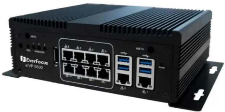
natural_image
Exterior view of a black EverFocus eIVP 5600 network switch with port labels and ports (no readable text beyond branding)
EverFocus
Copyright © EverFocus Electronics Corp.
Release Date: January 2020
EVERFOCUS ELECTRONICS CORPORATION
eIVP5600
Intel Gen7 Core i7-7600U/i5-7300U Mobile NVR supporting 8-Channel PoE IP Cameras
User's Manual
© 1995-2020 EverFocus Electronics Corp. www.everfocus.com.tw
Disclaimer
All the images including product pictures or screen shots in this document are for example only. The images may vary depending on the product and software version. Information contained in this document is subject to change without notice.
Copyright
All rights reserved. No part of the contents of this manual may be reproduced or transmitted in any form or by any means without written permission of the EverFocus Electronics Corporation.
- Microsoft Windows is a registered trademark of Microsoft Corp.
- Intel, Pentium, Celeron, and Xeon are registered trademarks of Intel Corporation
- Core, Atom are trademarks of Intel Corporation
- ITE is a trademark of Integrated Technology Express, Inc.
- IBM, PC/AT, PS/2, and VGA are trademarks of International Business Machines Corporation.
All other product names or trademarks are properties of their respective owners.
Safety Precautions
Please read the following safety instructions carefully. It is advised that you keep this manual for future references.
All cautions and warnings on the device should be noted.
All cables and adapters supplied by EverFocus are certified and in accordance with the material safety laws and regulations of the country of sale. Do not use any cables or adapters not supplied by EverFocus to prevent system malfunction or fires.
Make sure the power source matches the power rating of the device.
➢ Position the power cord so that people cannot step on it. Do not place anything over the power cord.
Always completely disconnect the power before working on the system's hardware.
No connections should be made when the system is powered as a sudden rush of power may damage sensitive electronic components.
If the device is not to be used for a long time, disconnect it from the power supply to avoid damage by transient over-voltage.
➢ Always disconnect this device from any AC supply before cleaning.
While cleaning, use a damp cloth instead of liquid or spray detergents.
Make sure the device is installed near a power outlet and is easily accessible.
Keep this device away from humidity.
Place the device on a solid surface during installation to prevent falls.
Do not cover the openings on the device to ensure optimal heat dissipation.
➢ Watch out for high temperatures when the system is running.
Do not touch the heat sink or heat spreader when the system is running.
➢ Never pour any liquid into the openings. This could cause fire or electric shock.
As most electronic components are sensitive to static electrical charge, be sure to ground yourself to prevent static charge when installing the internal components. Use a grounding wrist strap and contain all electronic components in any static-shielded containers.
If any of the following situations arises, please contact our service personnel (ts@everfocus.com.tw):
- Damaged power cord or plug
- Liquid intrusion to the device
- Exposure to moisture
- Device is not working as expected or in a manner as described in this manual
- The device is dropped or damaged
- Any obvious signs of damage displayed on the device
DO NOT LEAVE THIS DEVICE IN AN UNCONTROLLED ENVIRONMENT WITH TEMPERATURES BEYOND THE DEVICE'S PERMITTED STORAGE TEMPERATURES (SEE SPECIFICATION) TO PREVENT DAMAGE.
FCC Statement
Warning!

This device complies with Part 15 FCC Rules. Operation is subject to the following two conditions: (1) this device may not cause harmful interference, and (2) this device must accept any interference received including interference that may cause undesired operation.
Caution:
There is a danger of explosion if the battery is incorrectly replaced. Replace only with the same or equivalent type recommended by the manufacturer. Dispose of used batteries according to the manufacturer's instructions and your local government's recycling or disposal directives.
Attention:
1.1 Features .... 1
1.2 Dimensions.... 2
1.3 Packing List....2
1.4 Front Panel....3
1.5 Rear Panel 4
2. Connection and Installation.... 5
2.1 Storage Installation....5
2.1.1 mSATA drive Installation....5
2.1.2 2.5" SATA SSD/HDD Installation ....7
2.1.3 Storage Compatibility List 8
2.2 GPS Antenna Installation 9
2.3 RAM Installation....10
2.4 DC Out Cable 11
3. Jumpers and Connectors on the Motherboard 12
3.1 List of Jumpers 14
3.1.1 Clear CMOS (CN10) 14
3.1.2 ATX/AT Selection (CN14) 14
3.1.3 COM1 Ring/+5V/+12V Selection (CN15).... 14
3.1.4 CAN Bus UART/USB Selection (CN16).... 14
3.1.5 CAN Bus Program Firmware (CN18) 15
3.2 List of Connectors 16
3.2.1 Front Plane Connector (CN5).... 17
3.2.2 COM4 RS-232 Serial Port Connector (COM1) 17
3.2.3 COM3 RS-232 Serial Port Connector (COM2).... 18
3.2.4 COM1 & COM2 RS-232/422/485 Serial Port Connector (COM3).... 18
3.2.5 Digital I/O Connector (CN20) 18
3.2.6 Power In & Remote Button (CN19).... 19
3.2.7 CAN Bus 2.0B Connector (CN22)....19
3.2.8 Power on/off delay select (SW3)....19
4. AMI BIOS Setup....20
4.1 System Test and Initialization 20
4.2 AMI BIOS Setup 21
4.3 Setup Submenu: Main 21
4.4 Setup Submenu: Advanced....22
4.4.1 Advanced: CPU Configuration.... 22
4.4.2 Advanced: PCH-FW Configuration 23
4.4.3 Advanced: SATA Drives 23
4.4.4 Advanced: Trusted Computing 24
4.4.5 Advanced: Hardware Monitor 25
4.4.6 Advanced: SIO Configuration 25
4.4.6.1 SIO Configuration: Serial Port Configuration 26
4.4.6.2 SIO Configuration: Serial Port 1 Configuration.... 26
4.4.6.3 SIO Configuration: Serial Port 2 Configuration.... 27
4.4.6.4 SIO Configuration: Serial Port 3 Configuration 28
4.4.6.5 SIO Configuration: Serial Port 4 Configuration....28
4.4.6.6 SIO Configuration: Serial Port 5 Configuration....29
4.4.6.7 SIO Configuration: Serial Port 6 Configuration....30
4.4.7 Advanced: Digital IO Port Configuration.... 30
4.4.8 Advanced: Power Management 31
4.5 Setup Submenu: Chipset.... 32
4.5.1 Chipset: System Agent (SA) Configuration 32
4.5.1.1 System Agent (SA) Configuration: Graphics Configuration 33
4.6 Setup Submenu: Security.... 34
4.7 Setup Submenu: Boot 35
4.8 Setup submenu: Save & Exit 35
- Specification....36
1. Introduction
The eIVP5600 is one of EverFocus' eIVP series AI mobile NVRs adopting Intel® 7th Gen. Core™ i5/i7 Processor and Movidius™ Myriad™ X AI core module.
The model supports up to 8 PoE ports with individual LAN chips. Featuring smart PoE functionality, the eIVP5600 can remotely check or reboot the connected PoE devices if any of the PoE devices are not working properly.
The eIVP5600 also supports wide operating temperature ranging from -20^ to 70^ and wide DC range of DC 10-36V. It also features comprehensive storage options including up to two 2.5" HDD/SSD bays (optional) and an mSATA slot, and 2 RS-232/422/485 ports for connecting to other devices.
The eIVP5600 is complied with the MIL-STD-810G standard for the utmost viability for vehicular use. It supports onboard GPS, GLONASS and CAN bus. Besides, the model is also CE, FCC and RoHS certified. The eIVP5600 AI mobile NVR carries everything you need for computing on the road.
eIVP5600 Model SKU
SKU1: eIVP5600-i5 (i5-7300U; PoE x 4)
SKU2: eIVP5600-i5 (i5-7300U; PoE x 8)
SKU3: eIVP5600-i7 (i7-7600U; PoE x 4)
SKU4: eIVP5600-i7 (i7-7600U; PoE x 8)
1.1 Features
• In-vehicle network video recorder platform
- Intel® 7th Gen. Core™ i5/i7 processor
• 260-pin DDR4 2133 MHz SODIMM x 2, total up to 32GB (optional)
- Intel® Integrated Graphics Engine supports 2 display outputs by HDMI x 1, DP x 1
• Realtek® Ethernet x 10 ports (PoE x 8, GbE x 2)
• Supports up to 8-channel IP cameras
• Intel Movidius AI core module (optional)
• Supports CAN Bus 2.0B (optional)
• CE, FCC, RoHS certified
1.2 Dimensions
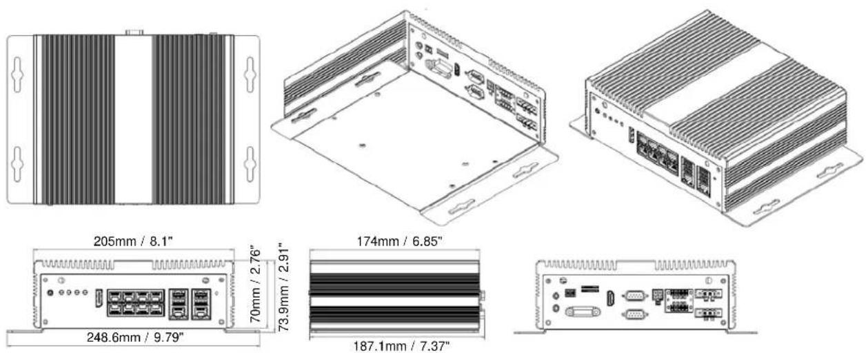
1.3 Packing List
- NVR x 1
• DC Power Terminal Block x 1 -
DC Out Cable x 1 (power supply for cameras)
-
mSATA Screw x 1
- 2.5" SATA SSD Installation Kit x 1 (includes 4 screws, 1 SATA cable, 1 SSD power cable)
- CD x 1 (see Note 3)
Note:
- Equipment configurations and supplied accessories vary by country. Please consult your local EverFocus office or agents for more information. Please also keep the shipping carton for possible future use.
- Contact the shipper if any items appear to have been damaged in the shipping process.
- The CD contains the User Manual and some Drivers for the system. If you can't find the required drivers from the CD, please go to our website for related drivers. www.everfocus.com.tw
1.4 Front Panel
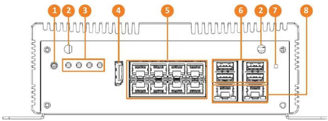
| No. | Name Description | |
| 1 | Power Button | Press the button to turn on or turn off the system. |
| 2 | Antenna | Connects the antenna to the mobile NVR for 3G / 4G / WiFi functions. |
| 3 | LED Indicator | HDD: When storage is reading/writing data, the LED will flashes green.Wireless 1-3: Mini Card WLED (Slot1 w/LED1, Slot2 w/LED2, Slot3 w/LED3. |
| 4 | DP Port | DP display output. |
| 5 | PoE Ports | LAN3~8 with PoE function for connecting to the IP cameras. |
| 6 | USB3.0 Ports | USB3.0 ports. |
| 7 | Reset | Press the button to restart the system. |
| 8 | LAN/WAN | Two 10/100/1000 Base-Tx Ethernet ports for connecting to the network. |
1.5 Rear Panel
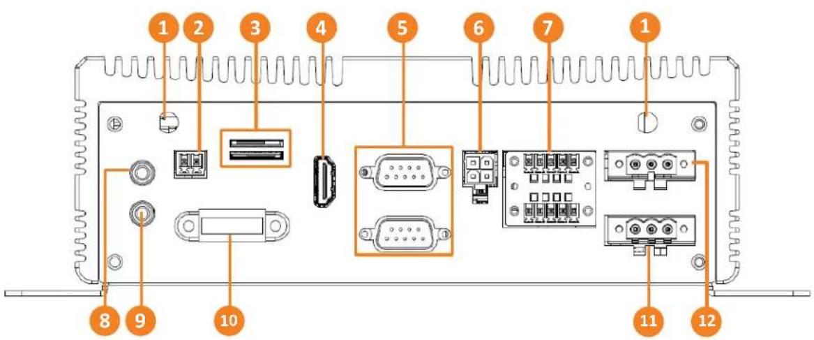
No. Name Description
| 1 | Antenna | Connects the antenna to the mobile NVR for 3G / 4G / WiFi functions. |
| 2 | CAN Bus | CAN Bus 2.0B Connector. |
| 3 | SIM Card Slot | SIM Card slots. |
| 4 | HDMI Port | HDMI display output. |
| 5 | COM Ports | RS-232 ports. |
| 6 | Power Output | A total of 12VDC, 2A power supply to the connected cameras. Please refer to 2.2 DC Power Out Cable. |
| 7 | Digital IO | Digital IO connector. |
| 8 | Audio Input | Connects to audio input devices, such as microphones. Note that the microphones with a (built-in) amplifier and external power supply are required. |
| 9 | Audio Output | Connects to an audio output device, such as speakers. Note that the speakers with a (built-in) amplifier and external power supply are required. |
| 10 | Fuse | Fuse Connector. |
| 11 | Power Input | Insert the supplied DC Power Terminal Block and then connect the system to a DC 10-36V power source. |
| 12 | Remote Power | Remote button. |
Chapter
2
2. Connection and Installation
2.1 Storage Installation
The eIVP5600 supports mSATA and 2.5" SATA SSD for storage.
2.1.1 mSATA drive Installation
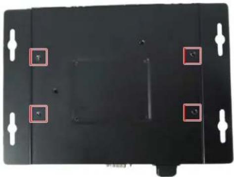
- Make sure the NVR is power-off.
- Unscrew the four screws on the bottom cover and then remove the bottom cover.
natural_image
Top-down view of a black electronic device with four mounting holes and red square markers (no text or symbols visible)- Unscrew the 6 screws.
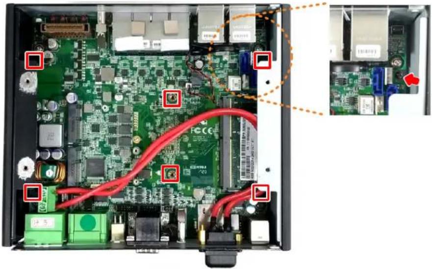
natural_image
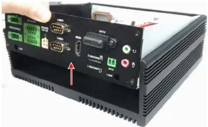
Interior view of an electronic device showing internal components with red wiring and labeled ports (no readable text or symbols)- Lift up the case to remove the top cover.
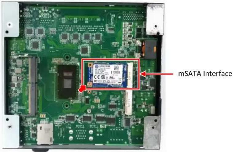
- Turn the case to the other side and find the mSATA interface on the motherboard. Screw your mSATA drive to the mSATA Interface using the supplied mSATA Screw.
- Screw back the top cover and bottom cover.
2.1.2 2.5" SATA SSD/HDD Installation
You can install one 2.5" SATA SSD/HDD inside the NVR.
- Make sure the NVR is power-off.
- Unscrew the four screws on the bottom cover and then remove the bottom cover from the housing.
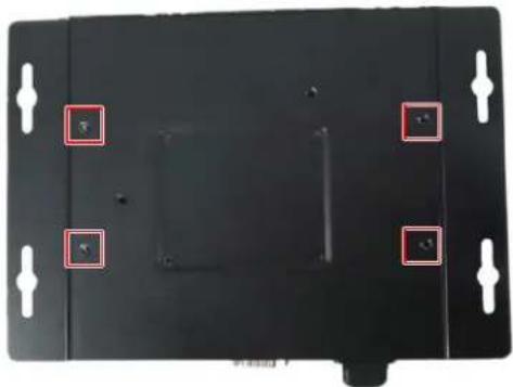
natural_image
Top-down view of a black electronic device casing with mounting holes and four red square markers highlighting features (no text or symbols)- Turn the bottom cover to the other side. Place an 2.5" SATA SSD onto the inner side of the bottom cover, align the SSD screw holes, and then use the supplied 4 screws to screw the SSD to the bottom cover from the outside of the bottom cover.
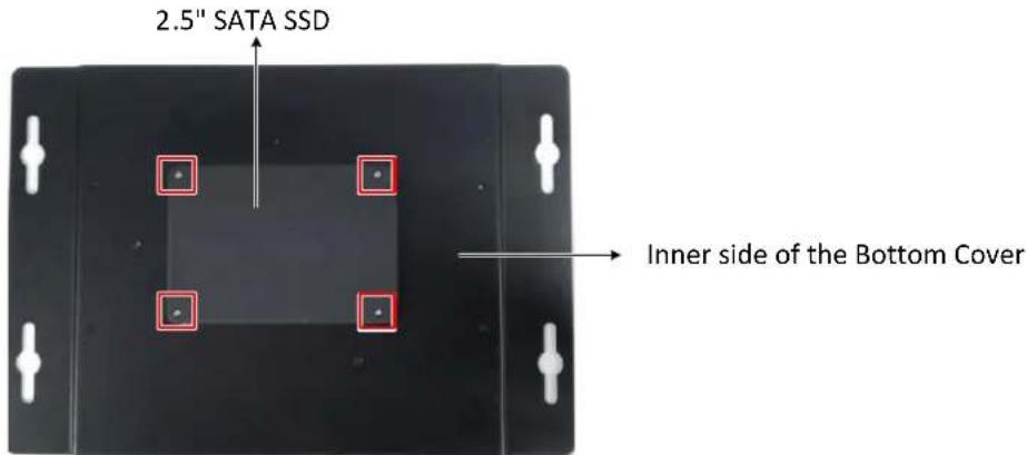
- Connect one end of the supplied SATA cable and SSD power cable to the motherboard.
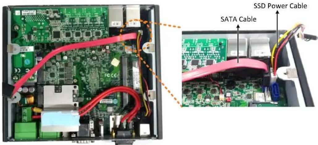
- Connect the other end of the SATA cable and SSD power cable to the SSD.
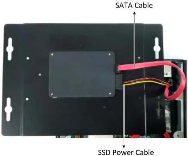
- Screw the bottom cover back to the housing.
2.1.3 Storage Compatibility List
Please go to the product page (Download) on EverFocus' Website www.everfocus.com.tw to see the latest Storage Compatibility List. It's recommended to use the storage models listed on the Storage Compatibility List to ensure your storage devices are compatible.
2.2 GPS Antenna Installation
The eIVP5600 supports onboard GPS. To enable the GPS function, connect a GPS Antenna to the antenna port.
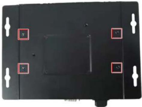
- Make sure the NVR is power-off.
- Unscrew the four screws on the bottom cover and then remove the bottom cover.
natural_image
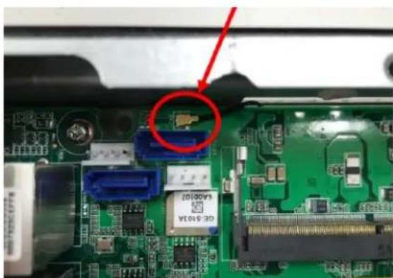
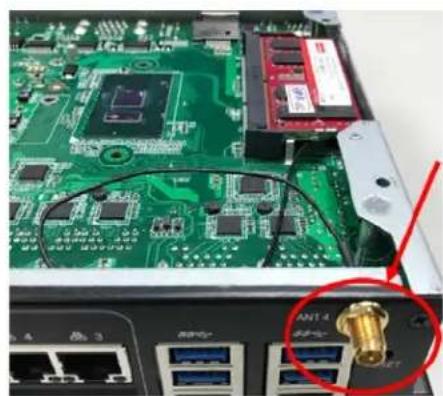
Top-down view of a black electronic device with four white mounting holes and red square markers (no text or symbols visible)- Find the GPS connector on the motherboard. Connect one end of the RF cable to the GPS connector and the other end to the Antenna port.
GPS Connector
natural_image
Close-up of a green printed circuit board with electronic components and a red circle highlighting a component (no readable text or symbols)Antenna Port
natural_image
Close-up of a green printed circuit board with internal components and a gold connector (no visible text or symbols)- Screw the GPS antenna to the Antenna port.
- Screw the bottom cover back to the model.
2.3 RAM Installation
The eIVP5600 supports 260-pin DDR4 2133 MHz SODIMM x 2. You can install the RAM on the DIMM port of the motherboard.
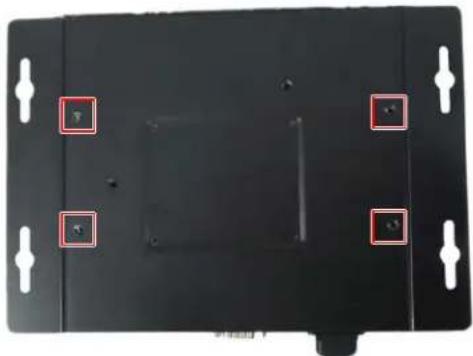
- Make sure the NVR is power-off.
- Unscrew the four screws on the bottom cover and then remove the bottom cover.
natural_image
Top-down view of a black electronic device with four white mounting holes and four red square markers highlighting features (no text or symbols)- Find the DIMM port on the motherboard and install the RAM.
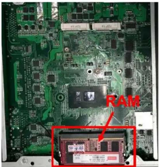
-
The second DIMM port is on the other side of the motherboard. To use the second DIMM port, follow Step 3 and Step 4 in 2.1 Storage Installation to remove the Top Cover from the model and turn the motherboard to the other side.
-
Screw back the front cover and bottom cover to the model.
2.4 DC Out Cable
The eIVP5600 provides a total of 12V/2A DC output with four sets of power output wires (+/-) for the connected IP cameras.
Connect the supplied DC Out Cable to the DC Out port on the rear panel of the NVR.
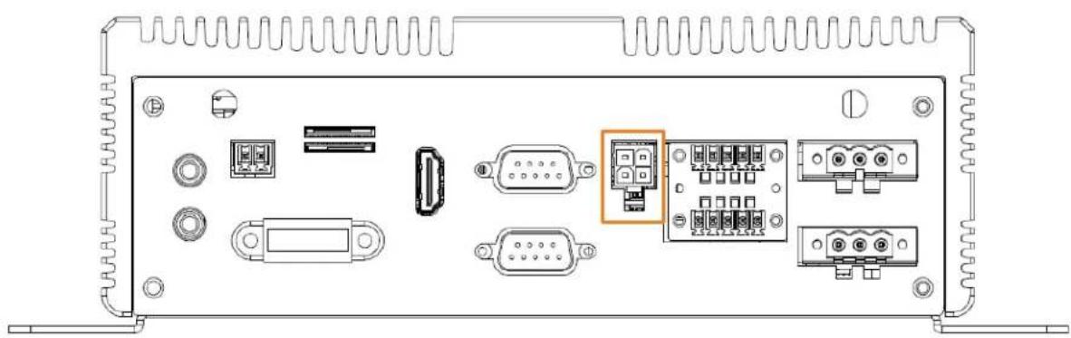
natural_image
Back panel diagram showing various electronic components including connectors, ports, and a central connector (no text or labels visible)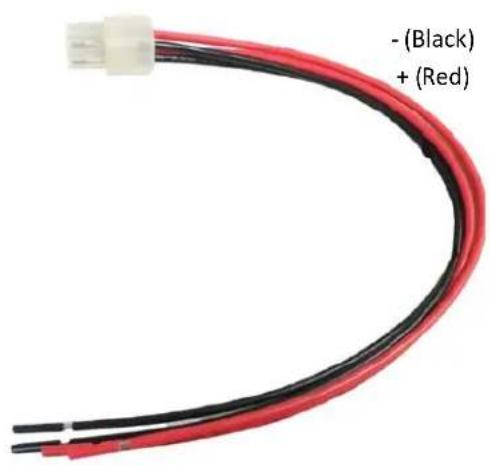
Chapter
3
3. Jumpers and Connectors on the Motherboard
Users can use the jumpers and connectors to configure different applications.
Component Side
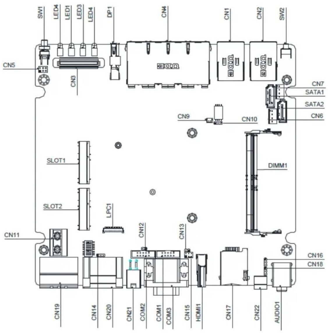
Solder Side
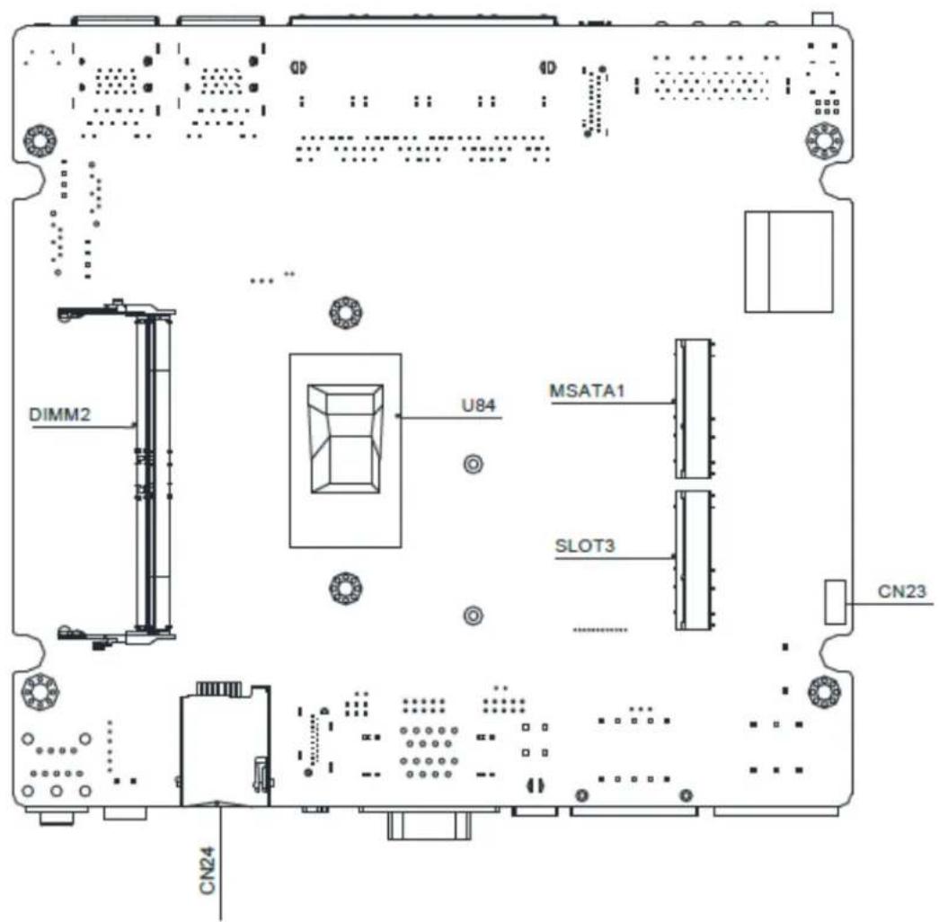
3.1 List of Jumpers
You can refer to the jumpers listed as below to configure your application.
| Label Function | |
| CN10 Clear CMOS | |
| CN14 ATX/AT Selection | |
| CH15 | COM1 Ring/ +5V/ +12V Selection |
| CN16 CAN Bus UART/USB Selection | |
| CN18 CAN Bus Program Firmware | |
3.1.1 Clear CMOS (CN10)
| Pin Function | |
| 1-2 Clear | |
| 2-3 Protected (Default) |
3.1.2 ATX/AT Selection (CN14)
| Pin Function | |
| 1-2 ATX | |
| 2-3 AT (Default) |
3.1.3 COM1 Ring/+5V/+12V Selection (CN15)
| Pin Function | |
| 1-2 + 5V | |
| 3-4 Ring (Default) | |
| 5-6 + 12V |
3.1.4 CAN Bus UART/USB Selection (CN16)
| Pin Function | |
| 1-2 UART | |
| 2-3 USB (Default) |
3.1.5 CAN Bus Program Firmware (CN18)
| Pin Function | |
| 1-2 Protected (Default) | |
| 2-3 Program | |
3.2 List of Connectors
You can refer to the connectors listed as below to configure your application.
| Label Function | |
| SW1 Power Button | |
| SW3 Software Reset | |
| SW4 | Power on/off delay selection |
| VGA1 CRT Port | |
| SW1 Power Button | |
| CN5 Front Panel | Connector |
| CN3 | Board to Board Connector |
| DP1 Display Port | |
| CN4 | LAN3~LAN6 (With PoE Function) |
| CN1 | USB3 & USB4 Connector with LAN2 (10/100/1000 Base-Tx Ethernet) Connector |
| CN2 | USB1 & USB2 Connector with LAN1 (10/100/1000 Base-Tx Ethernet) Connector |
| SW2 Software Reset | |
| CN19 | Power In & Remote Button |
| CN20 Digital I/O | Connector |
| CN21 + 12V Output | |
| COM1 | COM4 RS-232 Serial Port Connector |
| COM2 | COM3 RS-232 Serial Port Connector |
| COM3 | COM1 & COM2 RS-232/422/485 Serial Port Connector |
| HDMI1 HDMI | |
| CN17 SIM Card (With SLOT2) | |
| CN24 SIM Card (With SLOT3) | |
| CN22 CAN Bus 2.0B Connector | |
| AUDIO1 Audio Connector | |
| CN11 Fuse Connector | |
| SW3 Power on/off delay select | |
| DIMM1 DIMM2 | Slot |
| DIMM2 DIMM1 | Slot |
| SLOT1 | Mini Card Connector (only USB) half size |
| SLOT2 | Mini Card Connector (PCIe + USB) full size |
| SLOT3 | Mini Card Connector (only USB) full size |
| MSATA1 | Mini-SATA Connector |
| SATA1 | Primary Serial ATA Connector |
| SATA2 | Secondary Serial ATA Connector |
| LED4 SATA LED | |
| LED1~LED3 | Mini Card Wled(SLOT1 w/LED1, SLOT2 w/LED2, SLOT3 w/LED3 |
3.2.1 Front Plane Connector (CN5)
| Pin | Signal | Pin | Signal |
| 1 PWR_SW# 2 FPANSWH# | |||
| 3 GND 4 HWRST# | |||
| 5 GND 6 FPANSWH# |
3.2.2 COM4 RS-232 Serial Port Connector (COM1)
| Pin | Signal | Pin | Signal |
| 1 DCD 2 RXD | |||
| 3 TXD 4 DTR | |||
| 5 GND 6 DSR | |||
| 7 RTS 8 CTS | |||
| 9 | RI | 10 |
3.2.3 COM3 RS-232 Serial Port Connector (COM2)
| Pin | Signal | Pin | Signal |
| 1 DCD 2 RXD | |||
| 3 TXD 4 DTR | |||
| 5 GND 6 DSR | |||
| 7 RTS 8 CTS | |||
| 9 RI 10 |
3.2.4 COM1 & COM2 RS-232/422/485 Serial Port Connector (COM3)
| Pin | Signal | Pin | Signal |
| 1 DCD 2 RXD (RS422 RX-) | |||
| 3 | TXD (RS485 Data-/RS422 TX-) | 4 DTR (RS422 RX+) | |
| 5 GND 6 DSR | |||
| 7 RTS 8 CTS | |||
| 9 RI 10 |
3.2.5 Digital I/O Connector (CN20)
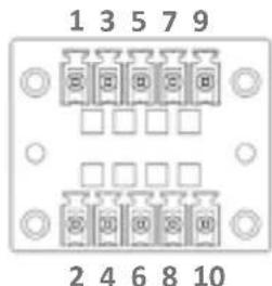
| Pin | Signal | Pin | Signal |
| 1 GND 2 +GP_V | |||
| 3 GPIO 4 GPO0 | |||
| 5 GPI1 6 GPO1 | |||
| 7 GPI2 8 GPO2 | |||
| 9 | GPI3 | 10 | GPO3 |
3.2.6 Power In & Remote Button (CN19)
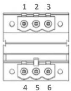
| Pin | Signal | Pin | Signal |
| 1 | ACC | 2 | GND_PRI |
| 3 PWR_IN 4 REMOTE_SW | |||
| 5 GND 6 PS_ON# | |||
3.2.7 CAN Bus 2.0B Connector (CN22)
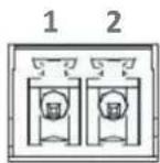
| Pin | Signal | Pin | Signal |
| 1 CAN DATA + 2 CAN | DATA - |
3.2.8 Power on/off delay select (SW3)
| Power On Delay Power Off Day | ||||||||
| Switch Pin Number | 6 | 7 | 8 | Time (sec.) | 5 | 4 | 3 | Time (sec.) |
| Control Table | off | off | off | 5 | off | off | off | 180 |
| off | off | on | 10 | off | off | on | 300 | |
| off | on | off | 15 | off | on | off | 900 | |
| off | on | on | 30 | off | on | on | 1800 | |
| on | off | off | Null | on | off | off | 2-Day | |
| on | off | on | Null | on | off | on | Null | |
| on | on | off | Null | on | on | off | Null | |
| on | on | on | Null | on | on | on | Null | |
4. AMI BIOS Setup
4.1 System Test and Initialization
The board uses certain routines to perform testing and initialization. If an error, fatal or non-fatal, is encountered, a few short beeps or an error message will be outputted. The board can usually continue the boot up sequence with non-fatal errors.
The system configuration verification routines check the current system configuration against the values stored in the CMOS memory. If they do not match, an error message will be outputted, in which case you will need to run the BIOS setup program to set the configuration information in memory.
There are three situations in which you will need to change the CMOS settings:
• You are starting your system for the first time
- You have changed your system's hardware
• The CMOS memory has lost power and the configuration information is erased
The system's CMOS memory uses a backup battery for data retention, which is to be replaced once emptied.
4.2 AMI BIOS Setup
The AMI BIOS ROM has a pre-installed Setup program that allows users to modify basic system configurations, which is stored in the batter y-backed CMOS RAM and BIOS NVRAM so that the information is retained when the power is turned off.
To enter BIOS Setup, press or
The function for each interface can be found below.
- Main – Date and time can be set here. Press
to switch between date elements - Advanced – Enable/ Disable boot option for legacy network devices
- Chipset – For hosting bridge parameters
- Boot – Enable/ Disable quiet Boot Option
• Security – The setup administrator password can be set here
• Save & Exit – Save your changes and exit the program
4.3 Setup Submenu: Main
Press the "Delete" key to enter the setup page.
![Aptio Setup Utility - Copyright (C) 2017 American Megatrends, Inc. Main Advanced Chipset Security Boot Save & Exit BIDS Information VPC-5600S R1.0 (VPS6AM10)(11/01/2017) BIDS Vendor Compliance System Date System Time Access Level American Megatrends UEFI 2.6: PI 1.4 [Tue 10/31/2017] [18:33:29] Administrator Set the Date. Use Tab to switch between Date elements. +#: Select Screen ↑#: Select Item Enter: Select +/-: Change Dot. F1: General Help F2: Previous Values F3: Optimized Defaults F4: Save & Exit ESC: Exit Version 2.18.1263. Copyright (C) 2017 American Megatrends, Inc.](/content/2026/06/1205420/images/c524f851674799adac56636759f8ccd5db49e836aa3482cef4d6ed1179e0038e.jpg)
4.4 Setup Submenu: Advanced
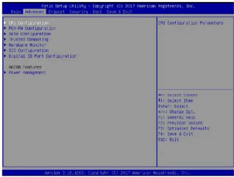
4.4.1 Advanced: CPU Configuration
![Optio Setup Utility - Copyright (C) 2017 American Megatrends, Inc. Advanced CPU Configuration Type Intel(R) Core(TM) IS-7100U CPU 6 2.40GHz ID ONB06E9 Speed 2400 MHz L1 Data Cache 32 KB x 2 L1 Instruction Cache 32 KB x 2 L2 Cache 256 KB x 2 LS Cache 8 MB L4 Cache N/A VMX Supported SMX/TXT Not Supported Active Processor Cores [ALL] Hyper-Threading [Enabled] Number of cores to enable in each processor package. +: Select Screen #: Select item Enter: Select +/-: Change Opt. F1: General Help F2: Previous Values F3: Optimized Defaults F4: Save & Exit ESC: Exit Version 8.18.126S, Copyright (C) 2017 American Megatrends, Inc.](/content/2026/06/1205420/images/66698be6c118a242b500c4297638e8c72f0282a3d297d8ebf99350149bf20d54.jpg)
Options summary:
| Active Processor Cores | All |
| 1 | |
| Number of cores to enable in each processor package. | |
| Hyper-Threading | Disabled |
| Enabled | |
| Enabled for Windows XP and Linux (OS optimized for Hyper-Threading Technology) and Disabled for other OS (OS not optimized for Hyper-Threading Technology). | |
4.4.2 Advanced: PCH-FW Configuration
![Aptio Setup Utility - Copyright (C) 2017 American Megatrends, Inc. Advanced ME Firmware Version 11.8.56.9425 ME Firmware Mode Normal Mode ME Firmware SKU Corporate SKU ME File System Integrity Value 2 ME Firmware Status 1 0x90000255 ME Firmware Status 2 0x80108305 NFC Support Disabled ME FX Image Re-Flash [Disabled] Enable/Disable Me FW Image Re-Flash function. +: Select Screen 14: Select Item Enter: Select +/-: Change Dot. F1: General Help F2: Previous Values F3: Optimized Defaults F4: Save & Exit ESC: Exit Version 2.18.1263 Copyright (C) 2017 American Megatrends, Inc.](/content/2026/06/1205420/images/b1f89aac5bcce79dc2ad223c928594106cce10860223a92c23cd60eb642b915e.jpg)
Options summary:
| ME FW Image Re-Flash | Disabled |
| Enabled | |
| Enable/Disable Me FW Image Re-Flash function. | |
4.4.3 Advanced: SATA Drives
![Aptio Setup Utility - Copyright (C) 2017 American Megatrends, Inc. advanced SATA And RST Configuration SATA Controller(s) SATA Mode Selection Serial ATA Port 0 Hot Plug Serial ATA Port 1 Hot Plug [Crabled] [AHCI] Empty [Disabled] Empty [Disabled] Enable/Disable SATA Device. 4+: Select Screen 11: Select Item Enter: Select +/-: Change Opt. F1: General Help F2: Previous Values F3: Optimized Defaults F4: Save A Exit ESC: Exit Version 2.18.1263 Copyright (C) 2017 American Megatrends, Inc.](/content/2026/06/1205420/images/7e0f0080e5805ae1d0c90db95382643684cf1d997364412283cae29cc383560b.jpg)
Options summary:
| SATA Controller(s) | Disabled |
| Enabled | |
| Enable/Disable SATA Device. | |
| Hot Plug | Disabled |
| Enabled | |
| Designates this port as Hot Pluggable. | |
4.4.4 Advanced: Trusted Computing
![Aptio Setup Utility - Copyright (C) 2017 American Megatrends, Inc. Advanced Configuration Security Device Support [Enable] TPM State [Enabled] Pending operation [None] Device Select [Auto] Current Status Information TPM Enabled Status: Enable TPM Active Status: Activated TPM Owner Status: Owned Enables or Disables BIOS support for security device: O.S. will not show Security Device. TCG EFI protocol and INTIA Interface will not be available. +: Select Screen ↑↓: Select Item Enter: Select +/-: Change Opt. F1: General Help F2: Previous Values F3: Optimized Defaults F4: Save & Exit ESC: Exit ++: Select Screen ↑↓: Select Item Enter: Select +/-: Change Opt. F1: General Help F2: Previous Values F3: Optimized Defaults F4: Save & Exit ESC: Exit Version 2.18.1263. Copyright (C) 2017 American Megatrends, Inc.](/content/2026/06/1205420/images/0c3f6b7ceed7ab4608c398e6b889218042b02605c6b079d62540d343ae341ab9.jpg)
Options summary:
| Security Device Support | Disabled |
| Enabled | |
| Enables or Disables BIOS support for security device. O.S. will not show Security Device. TCG EFI protocol and INT1A interface will not be available. | |
| TPM State | Disabled |
| Enabled | |
| Enable/Disable Security Device. NOTE: Your Computer will reboot during restart in order to change State of the Device. | |
| Pending operation | None |
| TPM Clear | |
| Schedule an Operation for the Security Device. NOTE: Your Computer will reboot during restart in order to change State of Security Device. | |
| Device Select | TPM 1.2 |
| TPM 2.0 | |
| Auto | |
| TPM1.2 will restrict support to TPM 1.2 devices, TPM 2.0 will restrict support to TPM 2.0 devices, Auto will support both with the default set to TPM 2.0 devices if not found, TPM 1.2 devices will be enumerated. | |
4.4.5 Advanced: Hardware Monitor
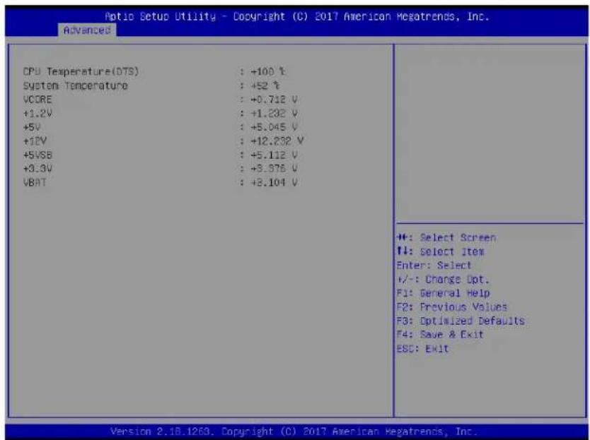
4.4.6 Advanced: SIO Configuration
![Action Setup Utility - Copyright (C) 2017 American Megatrends, Inc. Advanced AMI SIO Driver Version : AS.05.03 Super IO Chip Logical Device(s) Configuration [Active] Serial Port WARNING: Logical Devices state on the left side of the View and Set Basic properties of the SIO Logical device. Like IO Base, IRQ Range, OMA Channel and Device Mode. +: Select Screen TI: Select Item Enter: Select +/-: Change Opt. F1: General Help F2: Previous Values F3: Optimized Defaults F4: Save & Exit ESC: Exit Version 2.18.1263. Copyright (C) 2017 American Megatrends, Inc.](/content/2026/06/1205420/images/b7cc48ad04e6f2466a04b1f0bcb44e9ca002f1afd61629a86402b4dabba192f3.jpg)
4.4.6.1 SIO Configuration: Serial Port Configuration
![Aptio Setup Utility - Copyright (C) 2017 American Megatrends, Inc. Advanced AMI SID Driver Version : AS.07.03 Super IO Chio Logical Device(s) Configuration [×Active+] Serial Port 1 [×Active+] Serial Port 2 [×Active+] Serial Port 3 [×Active+] Serial Port 4 [×Active+] Serial Port 5 [×Active+] Serial Port 6 WARNING: Logical Devices state on the left side of the control, reflects the current Logical Device state. Changes made during Setup Session will be shown after you restart the system. View and Set Basic properties of the SID Logical device. Like IO Base, IRQ Range, DMA Channel and Device Mode. ++: Select Screen ++: Select Item Enter: Select +/-: Change Out. F1: General Help F2: Previous Values F3: Optimized Defaults F4: Save & Exit ESC: Exit Version 2.10.1269. Copyright (C) 2017 American Megatrends, Inc.](/content/2026/06/1205420/images/0b7e623add5c7f5de0e24e640e63ba8c6baff7bfa808be65ea5fd7729ec79277.jpg)
4.4.6.2 SIO Configuration: Serial Port 1 Configuration
![Aptio Setup Utility - Copyright (C) 2017 American Megatrends, Inc. Advanced Serial Port 1 Configuration Use This Device [Enabled] Logical Device Settings: Current : IO=OF8h; IRQ=4; Possible: [Use Automatic Settings] Mode : [RS232] WARNING: Disabling SIO Logical Devices may have unwanted side effects. PROCEED WITH CAUTION. Enable or Disable this Logical Device. +: Select Screen T1: Select Item Enter: Select +/-: Change Opt. F1: General Help F2: Previous Values F3: Optimized Defaults F4: Save & Exit ESC: Exit Version 2.10.1269. Copyright (C) 2017 American Megatrends, Inc.](/content/2026/06/1205420/images/b2b66d0a2d2bf2a81a599093e9d1154653fd6b62eddcbee330e950d83987e1ee.jpg)
Options summary:
| Use This Device | Disabled |
| Enabled | |
| Enable or Disable this Logical Device. | |
| Possible: | Use Automatic Settings |
| IO=2F8h; IRQ=3; | |
| IO=3F8h; IRQ=4; | |
| Allows user to change Device's Resource settings. New settings will be reflected on This Setup Page after System restarts. | |
| Mode | RS232 |
| RS422 | |
| RS485 | |
| UART RS232, 422, 485 selection. | |
4.4.6.3 SIO Configuration: Serial Port 2 Configuration
![Aptio Setup Utility - Copyright (C) 2017 American Megatrends, Inc. Advanced Serial Port 2 Configuration Use This Device [Enabled] Logical Device Settings: Current : IO=2F8h; IRQ=3; Possible: [Use Automatic Settings] Mode : [RS232] WARNING: Disabling SIO Logical Devices may have unwanted side effects. PROCEED WITH CAUTION. Enable or Disable this Logical Device. ++: Select Screen #1: Select Item Enter: Select +/-: Change Opt. F1: General Help F2: Previous Values F3: Optimized Defaults F4: Save & Exit ESC: Exit Version 2.10.1253. Copyright (C) 2017 American Megatrends, Inc.](/content/2026/06/1205420/images/b1e9658f6858b148d114c18d27324b61c75e05bfcbbd840c7bc2cbd404d8be40.jpg)
Options summary:
| Use This Device | Disabled |
| Enabled | |
| Enable or Disable this Logical Device. | |
| Possible: | Use Automatic Settings |
| IO=2F8h; IRQ=3; | |
| IO=3F8h; IRQ=4; | |
| Allows user to change Device's Resource settings. New settings will be reflected on this Setup Page after System restarts. | |
| Mode | RS232 |
| RS422 | |
| RS485 | |
| UART RS232, 422, 485 selection. | |
4.4.6.4 SIO Configuration: Serial Port 3 Configuration
![Optio Setup Utility - Copyright (C) 2017 American Megatrends, Inc. Advanced Serial Port 3: Configuration Use This Device [Enabled] Logical Device Settings: Current : 10=3EBhi JRO=11; Possible: [use automatic settings] WARNING: Disabling SID Logical Devices may have unwanted side effects. PROCEED WITH CAUTION. Enable or Disable this Logical Device. +: Select Screen T4: Select Item Enter: Select +/-: Change Opt. F1: General Help F2: Previous Values F3: Optimized Defaults F4: Save & Exit ESC: Exit Version 2.18.1263, Copyright (C) 2017 American Megatrends, Inc.](/content/2026/06/1205420/images/807170d5fb4eb4aeb0aff3b669dd3d1cae555658fd41db00a66d92014a058047.jpg)
Options summary:
| Use This Device | Disabled |
| Enabled | |
| Enable or Disable this Logical Device. | |
| Possible: | Use Automatic Settings |
| IO=2F8h; IRQ=3; | |
| IO=3F8h; IRQ=4; | |
| Allows user to change Device's Resource settings. New settings will be reflected on this Setup Page after System restarts. | |
4.4.6.5 SIO Configuration: Serial Port 4 Configuration
![Aotio Setup Utility - Copyright (C) 2017 American Megatrends, Inc. Advanced Serial Port 4. Configuration Use This Device [Enabled] Logical Device Settings: Current : IO=268h; IRQ=11; Possible: [Use Automatic Settings] WARNING: Disabling SIO Logical Devices may have unwanted side effects. PROCEED WITH CAUTION. Enable or Disable this Logical Device. ++: Select Screen !!: Select Item Enter: Select +/-: Change Opt. F1: General Help F2: Previous Values F3: Optimized Defaults F4: Save & Exit ESC: Exit Version 2.19.1263. Copyright (C) 2017 American Megatrends, Inc.](/content/2026/06/1205420/images/cda2747079dc05ace38979d71f41250ba1bc52cf387e1197b6aea3c9347822d0.jpg)
Options summary:
| Use This Device | Disabled |
| Enabled | |
| Enable or Disable this Logical Device. | |
| Possible: | Use Automatic Settings |
| IO=2F8h; IRQ=3; | |
| IO=3F8h; IRQ=4; | |
| Allows user to change Device's Resource settings. New settings will be reflected on this Setup Page after System restarts. | |
4.4.6.6 SIO Configuration: Serial Port 5 Configuration
![Aptio Setup Utility - Copyright (C) 2017 American Megatrends, Inc. Advanced Serial Port 5 Configuration Use This Device [Enabled] Logical Device Settings: Current : 16=20oh; IRQ=11; Possible: [Use Automatic Settings] WARNING: Disabling SIO Logical Devices may have unwanted side effects. PROCEED WITH CAUTION. Enable or Disable this Logical Device. +: Select Screen #: Select Item Enter: Select +/-: Change Opt. F1: General Help F2: Previous Values F3: Optimized Defaults F4: Save & Exit ESC: Exit ++: Select Screen #: Select Item Enter: Select +/-: Change Opt. F1: General Help F2: Previous Values F3: Optimized Defaults F4: Save & Exit ESC: Exit Version 2.18.1263. Copyright (C) 2017 American Megatrends, Inc.](/content/2026/06/1205420/images/c4238c242122e04622e830d0eec4986835775ab7e7b2fbcd024b03f6fb470b58.jpg)
Options summary:
| Use This Device | Disabled |
| Enabled | |
| Enable or Disable this Logical Device. | |
| Possible: | Use Automatic Settings |
| IO=2F8h; IRQ=3; | |
| IO=3F8h; IRQ=4; | |
| Allows user to change Device's Resource settings. New settings will be reflected on this Setup Page after System restarts. | |
4.4.6.7 SIO Configuration: Serial Port 6 Configuration
![Aptio Setup Utility - Copyright (C) 2017 American Megatrends, Inc. advanced Serial Port & Configuration Use This Device [Enabled] Logical Device Settings: Current : IO=20Oh; IRQ=11; Possible: [Use Automatic Settings] WARNING: Disabling SIO Logical Devices may have unwanted side effects. PROCEED WITH CAUTION. Enable or Disable this Logical Device. +: Select Screen ↑↓: Select Item Enter: Select +/-: Change Opt. F1: General Help F2: Previous Values F3: Optimized Defaults F4: Save & Exit ESC: Exit Version 2.18.1263. Copyright (C) 2017 American Megatrends, Inc.](/content/2026/06/1205420/images/2cc367875fd8cf6e7fd1f233400ef94cfd2134998f4270522fc4fe0a1b84f73c.jpg)
Options summary:
| Use This Device | Disabled |
| Enabled | |
| Enable or Disable this Logical Device. | |
| Possible: | Use Automatic Settings |
| IO=2F8h; IRQ=3; | |
| IO=3F8h; IRQ=4; | |
| Allows user to change Device's Resource settings. New settings will be reflected on this Setup Page after System restarts. | |
4.4.7 Advanced: Digital IO Port Configuration
![Aprio Setup Utility - Copyright (C) 2017 American Regatrends, Inc. Advanced Digital IO Port Configuration DIO Port1 [Input] DIO Port2 [Input] DIO Port3 [Input] DIO Port4 [Input] DIO Port5 [Output] Output Level [High] DIO Port6 [Output] Output Level [High] DIO Port7 [Output] Output Level [High] DIO Port8 [Output] Output Level [High] Set DIO as Input or Output +: Select Screen T1: Select Item Enter: Select +/-: Change Opt. F1: General Help F2: Previous Values F3: Optimized Defaults F4: Save & Exit ESC: Exit Version 2.18.1263. Copyright (C) 2017 American Regatrends, Inc.](/content/2026/06/1205420/images/6d7acac2b502ec7e1a721946334162bbf268807589445fa7566d2d608c7ff08b.jpg)
Options summary:
| DIO Port5~8 | Output |
| Set DIO as Output. | |
| Output Level | Low |
| High | |
| Set output level when DIO pin is output. | |
4.4.8 Advanced: Power Management
![Aptio Setup Utility - Copyright (C) 2017 American Megatrends, Inc. Advanced Power Management Power Mode [ATX Type] Restore AC Power Loss [Last State] Select system power mode. ++: Select Screen T#: Select Item Enter: Select +/-: Change Opt. F1: General Help F2: Previous Values F3: Optimized Defaults F4: Save & Exit ESC: Exit Version 8.18.1263, Copyright (C) 2017 American Megatrends, Inc.](/content/2026/06/1205420/images/cc8739ecc9922c0c0868f4f9f5b250a13f6f4d7ea232e970c97b3f0518277d9f.jpg)
Options summary:
| Power Mode | ATX Type |
| AT Type | |
| Select Power Supply Mode. | |
| Restore AC Power Loss | Power Off |
| Power On | |
| Last State | |
| Select AC power state when power is re-applied after a power failure. | |
4.5 Setup Submenu: Chipset
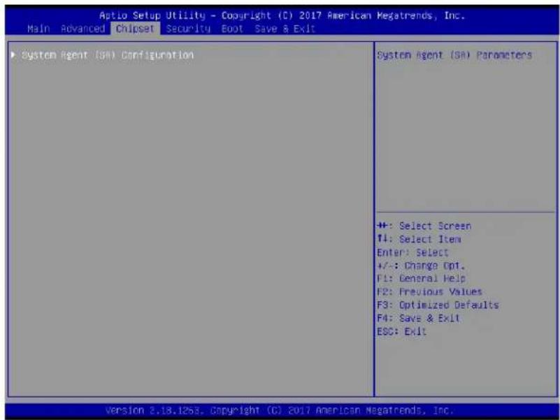
4.5.1 Chipset: System Agent (SA) Configuration
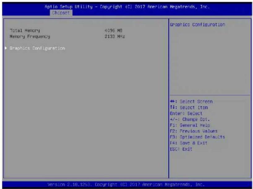
4.5.1.1 System Agent (SA) Configuration: Graphics Configuration
![Aptio Setup Utility - Copyright (C) 2017 American Megatrends, Inc. Chipset Graphics Configuration VT-d [Enabled] Primary Display [Auto] Primary IGFX Boot Display [VBIOS Default] VT-d capability +: Select Screen TI: Select Item Enter: Select +/-: Change Opt. F1: General Help F2: Previous Values F3: Optimized Defaults F4: Save & Exit ESC: Exit Version 2.16.1265, Copyright (C) 2017 American Megatrends, Inc.](/content/2026/06/1205420/images/86720734b30c804d45f6d1014e73e0decbba4ebe7cc89c90aef5231023c672b3.jpg)
Options summary:
| VT-d | Enabled |
| Disabled | |
| VT-d capability. | |
| Primary Display | Auto |
| IGFX | |
| PEG | |
| Select which of IGFX/PEG/PCI Graphics device should be Primary Display Or select SG for Switchable Gfx. | |
| Primary IGFX Boot Display | VBIOS Default |
| HDMI | |
| DP | |
| Select the Video Device which will be activated during POST. This has no effect if external graphics present. Secondary boot display selection will appear based on your selection. VGA modes will be supported only on primary display. | |
4.6 Setup Submenu: Security
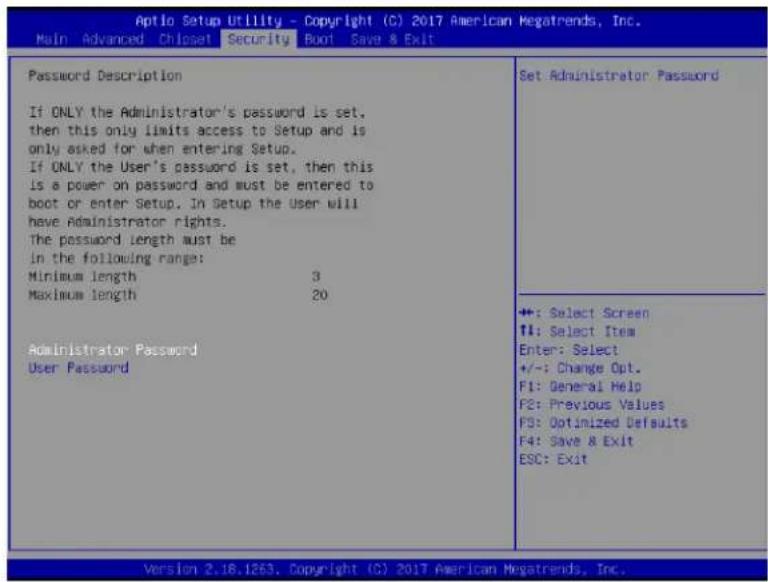
Change User/Administrator Password
You can set a User Password once an Administrator Password is set. The password will be required during boot up, or when the user enters the Setup utility. Please Note that a User Password does not provide access to many of the features in the Setup utility.
Select the password you wish to set, press Enter to open a dialog box to enter your password (you can enter no more than six letters or numbers). Press Enter to confirm your entry, after which you will be prompted to retype your password for a final confirmation. Press Enter again after you have retyped it correctly.
Removing the Password
Highlight this item and type in the current password. At the next dialog box press Enter to disable password protection.
4.7 Setup Submenu: Boot
![Aptio Setup Utility - Copyright (CI) 2017 American Megatrends, Inc. Main Advanced Chioset Security Boot Save & Exit Boot Configuration Quiet Boot [Enabled] Launch PXE ROM [Disabled] Boot Option Priorities Enables or disables Quiet Boot option ++: Select Screen 14: Select Item Enter: Select +/-: Change Dot. F1: General Help F2: Previous Values F3: Optimized Defaults F4: Save & Exit ESC: Exit Version 2.18.1263, Copyright (CI) 2017 American Megatrends, Inc.](/content/2026/06/1205420/images/c824a0e4bb279213bf0313d5fbbf41a47330778773e34e7b9ae7a18dcef6715e.jpg)
Options summary:
| Quite Boot | Disabled |
| Enabled | |
| Enables or disables Quiet Boot option. | |
| Launch PXE ROM | Disabled |
| Enabled | |
| Controls the execution of UEFI and Legacy PXE OpROM | |
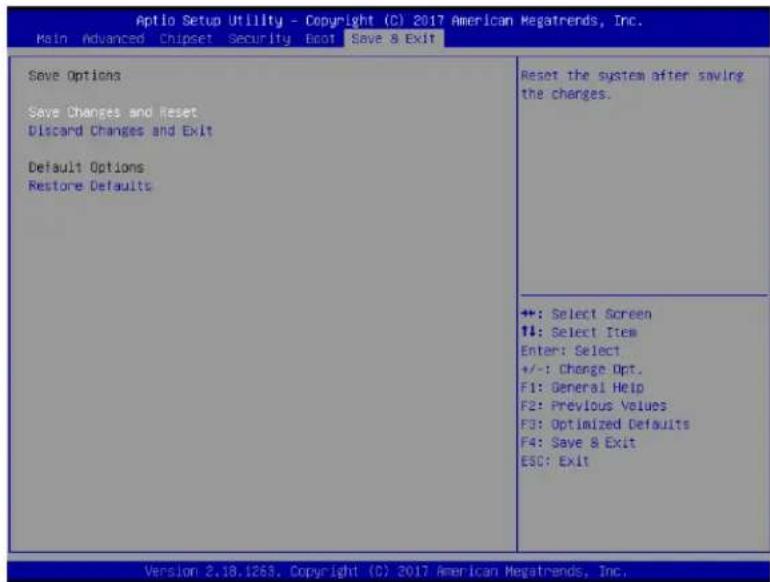
4.8 Setup submenu: Save & Exit
Chapter
5
- Specification
| Model No. | eIVP5600 | |
| System | Processor | Intel® 7th Gen. CoreTM i5/i7 Processor |
| Main Memory | Up to 32GB, DDR4 260-pin SODIMM (optional) | |
| Video | Format | H.264 / H.265 |
| Video Input | Up to 8 IP cameras | |
| Video Output | HDMI x 1, DP x 1 | |
| Audio | Audio Input Mic-in x 1 | |
| Audio Output | Line-out x 1 | |
| Recording | Format | H.264 / H.265 |
| Resolution | 1920 x 1080 at 30fps (NTSC) / 25fps (PAL) | |
| Storage | Internal HDD Bay | 2.5" HDD x 2 (optional) |
| Removable SSD | Hot swappable 2.5" SSD x 2 (project base) via extension module | |
| RAID | 0/1 | |
| CE / Cfast / mSATA | mSATA slot x 1 | |
| Network | Ethernet | RTL8111E 10/100/1000 based; GbE port x 2; PoE port x 4 (up to 8) (IEEE 802.3 at/af)* Every 4 PoE ports shares 60W of power budget |
| Wi-Fi | Supported | |
| 3G / 4G | Supported | |
| GPS / G-Sensor | On board (GPS/GLONASS), G-Sensor | |
| Alarm | Alarm Input | Digital input x 4 (wet/dry contact with Isolation Protection 3,000 VDC) |
| Alarm Output | Digital output x 4 (compatible 5 V/TTL, 31mA max. per channel) | |
| Interface Front I/O Panel | Power button x 13G/4G/WIFI LED x 3USB3.0 x 4GbE port (RJ-45) x 2PoE LAN x 4 (IEEE 802.3 at/af), max. 8 portsDP x 1Reset button x 1 | |
| Interface | Rear I/O Panel | DC-In power x 1Remote power x 18-bit DIO x 14ch digital input (wet/dry contact with Isolation Protection 3,000 VDC)4ch digital output (compatible 5 V/TTL, 31mA max. per channel)DC 12V/1A output x 1RS-232/422/485 x 2HDMI x 1CanBus connector x 1Audio line-out x 1Mic-in x 1SIM slot x 2 |
| Expansion Slot | Mini-Card slot x 3 (USB2.0 x 2 + PCIe & USB 2.0 x 1)Built-in CAN 2.0B x 1 | |
| General | Power Supply | DC 10-36V, with ignition pin |
| Dimensions (W x D X H) | 6.85'' x 8.07'' x 2.76'' / 174mm x 205mm x 70mm (without bracket) | |
| Gross Weight | 5.7lb (2.6kg) | |
| Operating | -4°F ~ 158°F (-20°C ~ 70°C); Project base: -40°C ~ 85°C | |
| Storage | -40°F ~ 185°F (-40°C ~ 85°C) | |
| Storage Humidity | 10%~80% @40°C, non-condensing | |
| Vibration/Shock | MIL-STD-810G | |
| Certification | CE & FCC Class A, RoHS | |
Note: All specifications are subject to change without notice.
EverFocus Electronics Corp.
EverFocus Taiwan:
2F., No.12, Ln. 270, Sec. 3, Beishen Rd., Shenkeng Dist., New Taipei City 222, Taiwan
TEL: +886 2 2662 2338
FAX: +886 2 2662 3632
www.everfocus.com.tw
marketing@everfocus.com.tw
EverFocus USA - California:
1801 Highland Avenue, Unit A, Duarte, CA 91010, USA
TEL: +1 626 844 8888
FAX: +1 626 844 8838
www.everfocus.com
sales@everfocus.com
EverFocus China - Shenzhen:
3F, Building 7, Longcheng Industrial Park, No.39, Longguan No.7 Road, Dalang Street, Longhua, Shenzhen, Guangdong, China
TEL: +86 755 2765 1313
FAX: +86 755 2765 0337
www.everfocus.com.cn
marketing@everfocus.com.cn
EverFocus Japan:
3F, Kuramochi, Building II, 2-2-3 Koto-Bashi, Sumida-Ku, Tokyo, 130-0022, Japan
TEL: +81 3 5625 8188
FAX: +81 3 5625 8189
www.everfocus.co.jp
info@everfocus.co.jp

Your EverFocus product is designed and manufactured with high quality materials and components which can be recycled and reused.
This symbol means that electrical and electronic equipment, at their end-of-life, should be disposed of separately from your household waste.
Please, dispose of this equipment at your local community waste
collection/recycling centre. In the European Union there are separate collection systems for used electrical and electronic product. Please, help us to conserve the environment we live in!
- EverFocus
- eIVP5600
- Intel Gen7 Core i7-7600U/i5-7300U Mobile NVR supporting 8-Channel PoE IP Cameras
- Disclaimer
- Copyright
- Safety Precautions
- FCC Statement
- Caution:
- Attention:
- Connection and Installation.... 5
- Jumpers and Connectors on the Motherboard 12
- AMI BIOS Setup....20
- Introduction
- eIVP5600 Model SKU
- Features
- Dimensions
- Packing List
- Note:
- Front Panel
- Rear Panel
- Chapter
- 2
- Connection and Installation
- Storage Installation
- mSATA drive Installation
- 2.5" SATA SSD/HDD Installation
- Storage Compatibility List
- GPS Antenna Installation
- RAM Installation
- DC Out Cable
- 3
- Jumpers and Connectors on the Motherboard
- List of Jumpers
- Clear CMOS (CN10)
- ATX/AT Selection (CN14)
- COM1 Ring/+5V/+12V Selection (CN15)
- CAN Bus UART/USB Selection (CN16)
- CAN Bus Program Firmware (CN18)
- List of Connectors
- Front Plane Connector (CN5)
- COM4 RS-232 Serial Port Connector (COM1)
- Power In & Remote Button (CN19)
- CAN Bus 2.0B Connector (CN22)
- Power on/off delay select (SW3)
- AMI BIOS Setup
- System Test and Initialization
- AMI BIOS Setup
- Setup Submenu: Main
- Setup Submenu: Advanced
- Advanced: CPU Configuration
- Options summary:
- Advanced: PCH-FW Configuration
- Advanced: SATA Drives
- Advanced: Trusted Computing
- Advanced: Hardware Monitor
- Advanced: SIO Configuration
- SIO Configuration: Serial Port Configuration
- SIO Configuration: Serial Port 1 Configuration
- SIO Configuration: Serial Port 2 Configuration
- SIO Configuration: Serial Port 3 Configuration
- SIO Configuration: Serial Port 4 Configuration
- SIO Configuration: Serial Port 5 Configuration
- SIO Configuration: Serial Port 6 Configuration
- Advanced: Digital IO Port Configuration
- Advanced: Power Management
- Setup Submenu: Chipset
- Chipset: System Agent (SA) Configuration
- System Agent (SA) Configuration: Graphics Configuration
- Setup Submenu: Security
- Setup Submenu: Boot
- Setup submenu: Save & Exit
- 5
- EverFocus Electronics Corp.
Brand : EverFocus
Model : EIVP-KBU-IV-V0004
Category : Security Camera