Tankless Rack System TRW02EP - Water heater Rinnai - Free user manual and instructions
Find the device manual for free Tankless Rack System TRW02EP Rinnai in PDF.

User questions about Tankless Rack System TRW02EP Rinnai
0 question about this device. Answer the ones you know or ask your own.
Ask a new question about this device
Download the instructions for your Water heater in PDF format for free! Find your manual Tankless Rack System TRW02EP - Rinnai and take your electronic device back in hand. On this page are published all the documents necessary for the use of your device. Tankless Rack System TRW02EP by Rinnai.
USER MANUAL Tankless Rack System TRW02EP Rinnai
Tankless Rack System Installation Manual
Additional information can be obtained from the appliance manual.

text_image
Free Standing Rack (6 water heaters)
WARNING
If the information in these instructions is not followed exactly, a fire or explosion may result causing property damage, personal injury or death.
— Do not store or use gasoline or other flammable vapors and liquids in the vicinity of this or any other appliance.
— WHAT TO DO IF YOU SMELL GAS
- Do not try to light any appliance.
- Do not touch any electrical switch; do not use any phone in your building.
- Immediately call your gas supplier from a neighbor's phone. Follow the gas supplier's instructions.
- If you cannot reach your gas supplier, call the fire department.
— Installation and service must be performed by a licensed professional.
Notes
Table of Contents
Description 4
Venting Options....4
TRS Part Nos. and Main Components....5
Specifications 8-27
Clearances 28
Hoisting (Lifting Lugs) 29
Securing Free Standing Racks 30
Securing Wall Mount Racks (ILW)....31
Securing Wall Hanging Racks (TRW)....32
Securing Wall Hanging Racks (TRC)....33
Relief Valve Piping 34
Piping for Multiple Racks 34
Parallel Piping Drawing 35
End Caps / Connections 36
Condensate Drain 37
Condensate Manifold 37
Checklist for Plumbing....38
Installation of Gas Supply....38
Connect Electricity....39
Electrical (Pre-wired electrical assembly) .....40
TRW ST Series Dedicated Return Line Plumbing Instructions....42
TRW ST Series Crossover Return Conversion Instructions....43
MSB Installation 47
Final Checklist....49
TRW Replacement Parts....50
TRC Replacement Parts....51
TRS Replacement Parts....52
Extended Limited Labor Warranty....54
Safety Symbols

This is the safety alert symbol. This symbol alerts you to potential hazards that can kill or hurt you and others.

DANGER
Indicates an imminently hazardous situation which, if not avoided, will result in death or serious injury.

WARNING
Indicates a potentially hazardous situation which, if not avoided, could result in death or serious injury.

CAUTION
Indicates a potentially hazardous situation which, if not avoided, could result in minor or moderate injury. It may also be used to alert against unsafe practices.
Installation
A licensed professional must install the (TRS) Tankless Rack System
The installer should have skills such as
- connecting gas lines, water lines, valves, and electricity
- knowledge of applicable national, state, and local codes
If you lack these skills, contact a licensed professional.
3 Rinnai Rack Installation
Description
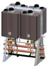
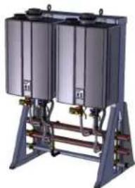
Rinnai Tankless Rack Systems (TRS) include wall mounted and free standing configurations. The wall mounted rack systems are available for 2 or 3 water heaters. Free standing rack systems are available for 2, 3, 4, 5, or 6 water heaters.
The TRS can be ordered with Rinnai's Common Venting System, which consists of the CVent exhaust venting and PP or PVC intake venting. Up to eight tankless units can share the same CVent system.
The Rinnai TRS features design details that make installation simple and straightforward.
- Maneuverability: Fits, fully assembled, through standard 32-inch doorways and on elevators
• Flexibility: Available in both wall-mount or freestanding design for indoor and outdoor installations. - Preassembled Gas and water manifolds are properly sized to maintain optimum performance.
- The racks are constructed of powder-coated aluminum, powder coated steel, and stainless to stand up to the most demanding commercial environments, while minimizing weight.
• Optional electronic controls to obtain turn down ratios of up to 327:1 (Sold Separately).
NOTE: The TRS is designed to be used with Rinnai tankless water heaters only. Do not mount non-Rinnai water heaters on the TRS.
Venting Options
| Venting Options | Exhaust Vent Material | Intake Vent Material | Diameter | Max. Units | Max. Vent Length | |
| Natural Gas Propane | ||||||
| Common Venting System ** | PPtl, PPs | PVC, PPtl, PPS | 8" | 8 | 100' (with 7 units) or 41' (with 8 units) | |
| Concentric | PPs | PVC | 5" | 1 | 65' | 45' |
| Twin Pipe PVC/CPVC PVC/CPVC | VC | PVC/CPVC | 4" | 1 | 100' | 65' |
| 3" | 1 | 65' | 41' | |||
| Dual Pipe* | PPs | PPs or PVC | 3" | 1 | 41' | 41 |
| *This venting is provided by Centrotherm through their own distribution network | ||||||
- Refer to the water heater installation and operation manual for specific details regarding vent installation option and installation.
- Venting components are packaged separately from the pre-assembled Rack for field assembly of the vent system by the contractor.
**Only the C199i is certified for both direct vent and exhaust only with room air (exhaust must terminate vertically in room air application) when installed in a commercial common vent application only. Reference Rinnai Common Vent (CVent) Manual for further information.
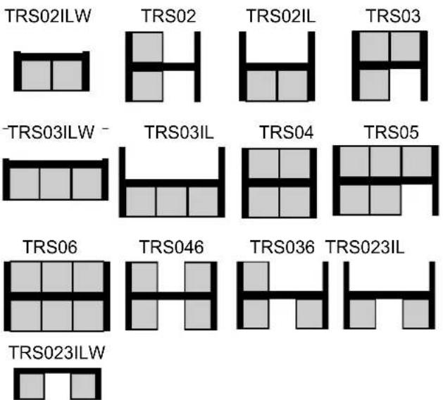
TRS Part Nos. and Main Components
Tankless Rack WALL HANGING
| Part No.* | Rack type | Configuration | Illustration |
| TRW02iN | 2-unit interior wall hanging rack, NG |  | 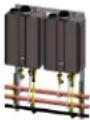 |
| TRW02eN | 2-unit exterior wall hanging rack, NG | ||
| TRW02iP | 2-unit interior wall hanging rack, LP | ||
| TRW02eP | 2-unit exterior wall hanging rack, LP | ||
| TRW23iN | 2-unit interior wall hanging rack, NG | - -  | 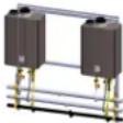 |
| TRW23eN | 2-unit exterior wall hanging rack, NG | ||
| TRW23iP | 2-unit interior wall hanging rack, LP | ||
| TRW23eP | 2-unit exterior wall hanging rack, LP | ||
| TRW03iN | 3-unit interior wall hanging rack, NG | - -  | 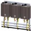 |
| TRW03eN | 3-unit exterior wall hanging rack, NG | ||
| TRW03iP | 3-unit interior wall hanging rack, LP | ||
| TRW03eP | 3-unit exterior wall hanging rack, LP |
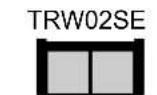
Tankless Rack WALL HANGING SE SERIES
| Part No.* | Rack type | Configuration | Illustration |
| TRW02SEiN | 2-unit interior wall hanging rack, NG RUC |  | 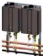 |
| TRW02SEeN | 2-unit exterior wall hanging rack, NG RUC | ||
| TRW02SEiP | 2-unit interior wall hanging rack, LP RUC | ||
| TRW02SEeP | 2-unit exterior wall hanging rack, LP RUC |
Tankless Rack WALL HANGING ST SERIES
| Part No.* | Rack type | Configuration | Illustration |
| TRW02STiN | 2-unit interior wall mount rack, NG |  |  |
| TRW02STeN | 2-unit exterior wall mount rack, NG | ||
| TRW02STiP | 2-unit interior wall mount rack, LP | ||
| TRW02STeP | 2-unit exterior wall mount rack, LP | ||
| TRW03STiN | 2-unit interior wall mount rack, NG | - - |  |
| TRW03STeN | 2-unit exterior wall mount rack, NG | 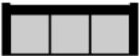 | |
| TRW03STiP | 2-unit interior wall mount rack, LP | ||
| TRW03STeP | 2-unit exterior wall mount rack, LP |
TRS Part Nos. and Main Components
Tankless Rack CORNER HANGING
| Part No.* | Rack type | Configuration | Illustration |
| TRC02iN | 2-unit interior corner hanging rack, NG |  | 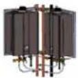 |
| TRC02iP | 2-unit interior corner hanging rack, LP |
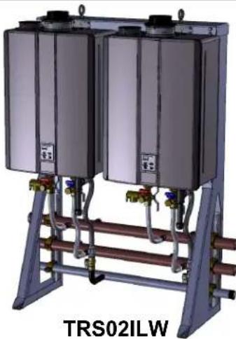
Tankless Rack INLINE WALL MOUNT
| Part No.* | Rack type | Configuration | Illustration |
| TRS02ILWiN | 2-unit interior wall mount rack, NG | 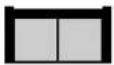 | 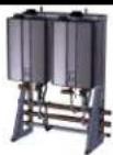 |
| TRS02ILWeN | 2-unit exterior wall mount rack, NG | ||
| TRS02ILWiP | 2-unit interior wall mount rack, LP | ||
| TRS02ILWeP | 2-unit exterior wall mount rack, LP | ||
| TRS23ILWiN | 2-unit interior wall mount rack, NG | - 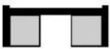 |  |
| TRS23ILWeN | 2-unit exterior wall mount rack, NG | ||
| TRS23ILWiP | 2-unit interior wall mount rack, LP | ||
| TRS23ILWeP | 2-unit exterior wall mount rack, LP | ||
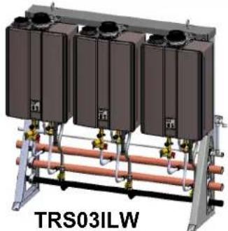
| TRS03ILWiN | 3-unit interior wall mount rack, NG | - - |  |
| TRS03ILWeN | 3-unit exterior wall mount rack, NG |  | |
| TRS03ILWiP | 3-unit interior wall mount rack, LP | ||
| TRS03ILWeP | 3-unit exterior wall mount rack, LP |
Part no. system:
TR = tankless rack; W = wall hanging; S = stand alone; IL = inline; ILW = Inline Wall Mount; 2/3/4/5/6 = no. of water heaters; i/e = interior/exterior; NG/LP = fuel type
TRS Part Nos. and Main Components
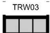
Tankless Rack FREESTANDING
| Part No.* | Rack type | Configuration | Illustration | ||
| TRS02iN | 2-unit interior free standing rack, NG | Back to Back |  |  | |
| TRS02eN | 2-unit exterior free standing rack, NG | ||||
| TRS02iP | 2-unit interior free standing rack, LP | ||||
| TRS02eP | 2-unit exterior free standing rack, LP | ||||
| TRS02ILiN | 2-unit INLINE interior free standing rack, NG | 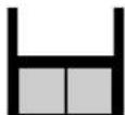 | 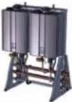 | ||
| TRS02ILeN | 2-unit INLINE exterior free standing rack, NG | ||||
| TRS02ILiP | 2-unit INLINE interior free standing rack, LP | ||||
| TRS02ILeP | 2-unit INLINE exterior free standing rack, LP | ||||
| TRS23ILiN | 2-unit INLINE interior free standing rack, NG |  |  | ||
| TRS23ILeN | 2-unit INLINE exterior free standing rack, NG | ||||
| TRS23ILiP | 2-unit INLINE interior free standing rack, LP | ||||
| TRS23ILeP | 2-unit INLINE exterior free standing rack, LP | ||||
| TRS03ILiN | 3-unit INLINE interior free standing rack, NG |  |  | ||
| TRS03ILeN | 3-unit INLINE exterior free standing rack, NG | ||||
| TRS03ILiP | 3-unit INLINE interior free standing rack, LP | ||||
| TRS03ILeP | 3-unit INLINE exterior free standing rack, LP | ||||
| TRS03iN | 3-unit interior free standing rack, NG |  |  | ||
| TRS03eN | 3-unit exterior free standing rack, NG | ||||
| TRS03iP | 3-unit interior free standing rack, LP | ||||
| TRS03eP | 3-unit exterior free standing rack, LP | ||||
| TRS36iN | 3-unit interior free standing rack, NG | 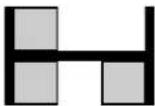 | 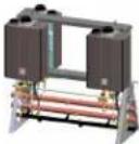 | ||
| TRS36eN | 3-unit exterior free standing rack, NG | ||||
| TRS36iP | 3-unit interior free standing rack, LP | ||||
| TRS36eP | 3-unit exterior free standing rack, LP | ||||
| TRS04iN | 4-unit interior free standing rack, NG |  |  | ||
| TRS04eN | 4-unit exterior free standing rack, NG | ||||
| TRS04iP | 4-unit interior free standing rack, LP | ||||
| TRS04eP | 4-unit exterior free standing rack, LP | ||||
| TRS46iN | 4-unit interior free standing rack, NG |  | 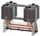 | ||
| TRS46eN | 4-unit exterior free standing rack, NG | ||||
| TRS46iP | 4-unit interior free standing rack, LP | ||||
| TRS46eP | 4-unit exterior free standing rack, LP | ||||
| TRS05iN | 5-unit interior free standing rack, NG |  |  | ||
| TRS05eN | 5-unit exterior free standing rack, NG | ||||
| TRS05iP | 5-unit interior free standing rack, LP | ||||
| TRS05eP | 5-unit exterior free standing rack, LP | ||||
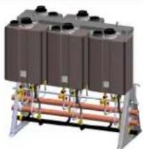
| TRS06iN | 6-unit interior free standing rack, NG |  |  | ||
| TRS06eN | 6-unit exterior free standing rack, NG | ||||
| TRS06iP | 6-unit interior free standing rack, LP | ||||
| TRS06eP | 6-unit exterior free standing rack, LP | ||||
Part no. system: TR = tankless rack; W = wall hanging; S = stand alone; IL = inline; ILW = Inline Wall Mount; 2/3/4/5/6 = no. of water heaters; i/e = interior/exterior; NG/LP = fuel type
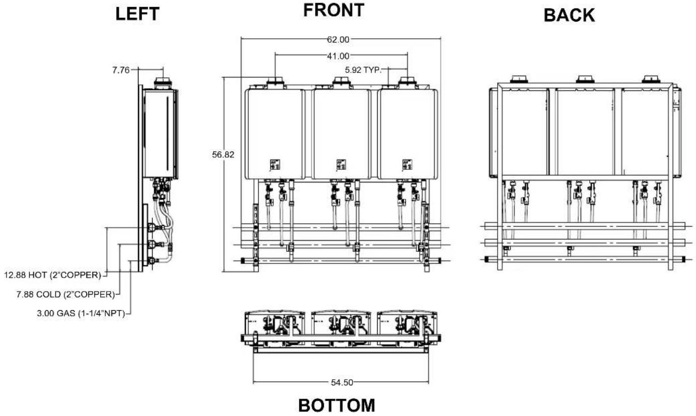
Specifications
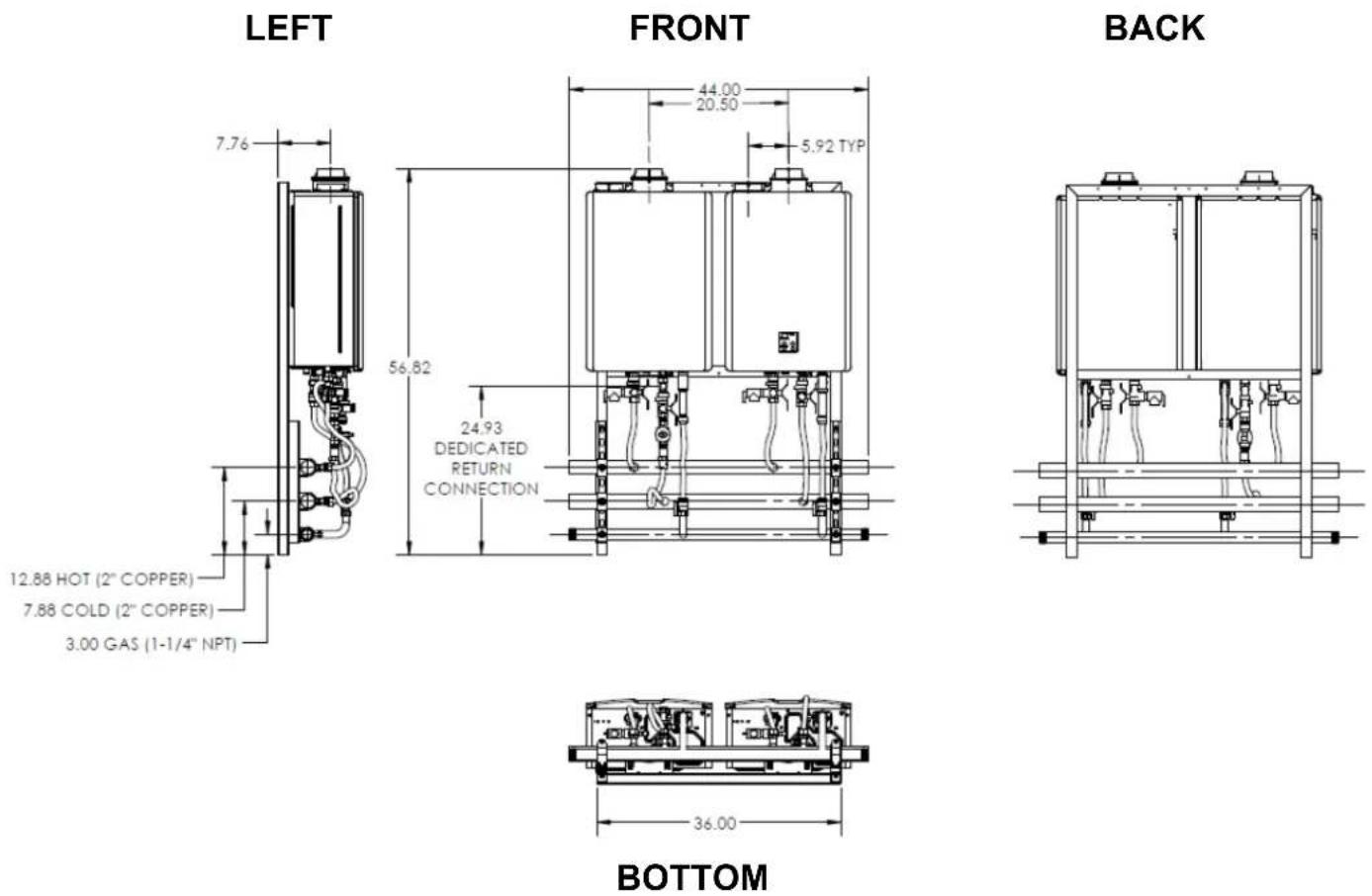
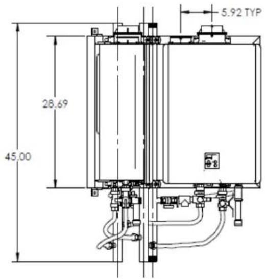
2 UNIT WALL HANGING FRAME
LEFT

text_image
7.76 12.88 HOT (2"COPPER) 7.88 COLD (2"COPPER) 3.00 GAS (1-1/4"NPT)FRONT

text_image
44.00 20.50 5.92 TYP. 56.82BACK

natural_image
Technical line drawing of a mechanical device with multiple ports and mounting brackets (no text or symbols)
text_image
36.00BOTTOM
| Model | Configuration | Illustration |
| TRW02 |  | 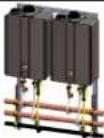 |
Specifications
| 2 UNIT WALL HANGING FRAME | ||
| Model | TRW02i TRW02e | |
| Water Heater Model | C199i (NG/LP) | C199e (NG/LP) |
| Crate Dimensions (HxLxD) - in 66 x 67 x 35 | ||
| Weight - Fully Assembled - lbs | 166 | 165 |
| Weight - Shipping (total) - lbs | 380 | 379 |
| Rack Frame - Specifications | ||
| Frame Material | 14 Gauge Hot Rolled Steel 1.5" Square Tube 16 Gauge Stainless Steel 1.5" Square Tube | |
| Frame Finish Powder Coat Stainless | ||
| Color Gray Stainless | ||
| Water & Gas Connections | ||
| Hot Water Trunk Line Diameter 2" | ||
| Cold Water Trunk Line Diameter | 2" | |
| Hot Water Trunk Line Material | Rigid Copper | |
| Cold Water Trunk Line Material | Rigid Copper | |
| Water Trunk Connection Type | 2" PIPE | |
| Gas Trunk Line Diameter | 1-1/4" | |
| Gas Trunk Connection Type | 1-1/4" MNPT | |
| Gas Trunk Line Material | Sch 40 Steel | |
| Gas Branch Line Material | PVC Over CSST | |
| Electric Requirements | ||
| Voltage AC 120 Volts—60 Hz | ||
| Maximum Current (Amperes) | 8 | |
| BTU and Flow Rates for C199i, C199e (NG/LP) | ||
| Number of Tankless Water Heaters | 2 | |
| Flow rate @ 70°F rise (gpm) | 10.8 | |
| Flow rate @ 100°F rise (gpm) | 7.6 | |
| Minimum input rate (Btuh) | 15,200 | |
| Maximum input rate (Btuh) | 398,000 | |

natural_image
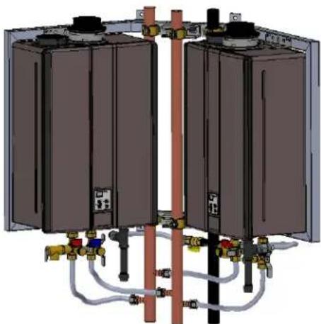
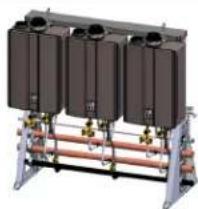
3D rendering of two industrial tanks mounted on a pipe with valves and pipes, labeled TRW02 (no text or symbols on the equipment itself)3 UNIT WALL HANGING FRAME
FRONT
| Model | Configuration | Illustration |
| TRW03 |  |  |
| TRW23 |  | 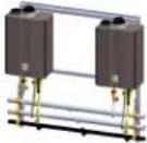 |
Specifications
| 3 UNIT WALL HANGING FRAME | ||||
| Model | TRW03i | TRW03e | TRW23i | TRW23e |
| Water Heater Model | C199i (NG/LP) | C199e (NG/LP) | C199i (NG/LP) | C199e (NG/LP) |
| Crate Dimensions (HxLxD) - in | 66 x 67 x 35 | 66 x 67 x 35 | ||
| Weight - Fully Assembled - lbs | 244 | 240 | 182 | 179 |
| Weight - Shipping (total) - lbs | 458 | 454 | 396 | 393 |
| Rack Frame - Specifications | ||||
| Frame Material | 14 Gauge Hot Rolled Steel 1.5" Square Tube | 16 Gauge Stainless Steel 1.5" Square Tube | 14 Gauge Hot Rolled Steel 1.5" Square Tube | 16 Gauge Stainless Steel 1.5" Square Tube |
| Frame Finish | Powder Coat | Stainless | Powder Coat | Stainless |
| Color | Gray | Stainless | Gray | Stainless |
| Water & Gas Connections | ||||
| Hot Water Trunk Line Diameter 2" | ||||
| Cold Water Trunk Line Diameter 2" | ||||
| Hot Water Trunk Line Material Rigid Copper | ||||
| Cold Water Trunk Line Material Rigid Copper | ||||
| Water Trunk Connection Type 2" PIPE | ||||
| Gas Trunk Line Diameter 1-1/4" | ||||
| Gas Trunk Connection Type | 1-1/4" MNPT | |||
| Gas Trunk Line Material | Sch 40 Steel | |||
| Gas Branch Line Material | PVC Over CSST | |||
| Electric Requirements | ||||
| Voltage | AC 120 Volts—60 Hz | |||
| Maximum Current (Amperes) | 12 | 8 | ||
| BTU and Flow Rates for C199i, C199e (NG/LP) | ||||
| Number of Tankless Water Heaters | 3 | 2 | ||
| Flow rate @ 70°F rise (gpm) | 16.2 | 10.8 | ||
| Flow rate @ 100°F rise (gpm) | 11.4 | 7.6 | ||
| Minimum input rate (Btuh) | 15,200 | 15,200 | ||
| Maximum input rate (Btuh) | 597,000 | 398,000 | ||
natural_image
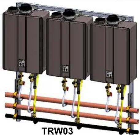
3D rendering of three identical industrial tanks mounted on a red pipe with yellow and gold fittings, labeled 'TRW03' at the bottom (no other text or symbols visible)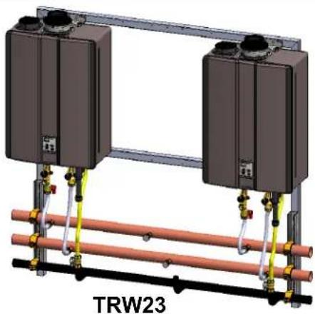
natural_image
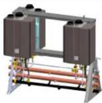
3D rendering of two identical industrial tanks mounted on a metal frame with pipes and valves, labeled 'TRW23' at the bottom (no other text or symbols)11 Rinnai Rack Installation
Specifications
2 UNIT WALL HANGING FRAME SE SERIES

| Model | Configuration | Illustration |
| TRW02SE | | |
Specifications
| 2 UNIT WALL HANGING FRAME SE SERIES | ||
| Model | TRW02SEi TRW02SEe | |
| Water Heater Model | RUC98i (NG/LP) | RU98e (NG/LP) |
| Crate Dimensions (HxLxD) - in 66 X 67 X 35 | ||
| Weight - Fully Assembled - lbs | 166 | 165 |
| Weight - Shipping (total) - lbs | 380 | 379 |
| Rack Frame - Specifications | ||
| Frame Material | 14 Gauge Hot Rolled Steel 1.5" Square Tube 16 Gauge Stainless Steel 1.5" Square Tube | |
| Frame Finish Powder Coat Stainless | ||
| Color Gray Stainless | ||
| Water & Gas Connections | ||
| Hot Water Trunk Line Diameter 2" | ||
| Cold Water Trunk Line Diameter | 2" | |
| Hot Water Trunk Line Material | Rigid Copper | |
| Cold Water Trunk Line Material | Rigid Copper | |
| Water Trunk Connection Type | 2" PIPE | |
| Gas Trunk Line Diameter | 1-1/4" | |
| Gas Trunk Connection Type | 1-1/4" MNPT | |
| Gas Trunk Line Material | Sch 40 Steel | |
| Gas Branch Line Material | PVC Over CSST | |
| Electric Requirements | ||
| Voltage | AC 120 Volts—60 Hz | |
| Maximum Current (Amperes) | 8 | |
| BTU and Flow Rates for RUC98i, RU98e (NG/LP) | ||
| Number of Tankless Water Heaters | 2 | |
| Flow rate @ 70°F rise (gpm) | 10.8 | |
| Flow rate @ 100°F rise (gpm) | 7.6 | |
| Minimum input rate (Btuh) | 15,200 | |
| Maximum input rate (Btuh) | 398,000 | |
natural_image
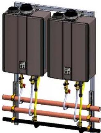
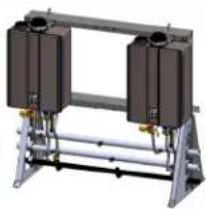
3D rendering of two identical industrial tanks mounted on a copper pipe with piping and valves (no text or symbols visible)TRW02
Specifications
2 UNIT WALL HANGING FRAME ST SERIES WITH THERMACIRC 360
| Model | Configuration | Illustration |
| TRW02ST |  | 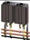 |
Specifications
| 2 UNIT WALL HANGING FRAME ST SERIES WITH THERMACIRC 360 | ||
| Model | TRW02STi TRW02STe | |
| Water Heater Model | RUR98i AND RUC98i (NG/LP) | RUR98e AND RU98e (NG/LP) |
| Crate Dimensions (HxLxD) - in 66X67X35 | ||
| Weight - Fully Assembled - lbs | 174 | 173 |
| Weight - Shipping (total) - lbs | 388 | 387 |
| Rack Frame - Specifications | ||
| Frame Material | 14 Gauge Hot Rolled Steel 1.5" Square Tube 16 Gauge Stainless Steel 1.5" Square Tube | |
| Frame Finish Powder Coat Stainless | ||
| Color Gray Stainless | ||
| Water & Gas Connections | ||
| Hot Water Trunk Line Diameter 2" | ||
| Cold Water Trunk Line Diameter | 2" | |
| Hot Water Trunk Line Material | Rigid Copper | |
| Cold Water Trunk Line Material | Rigid Copper | |
| Water Trunk Connection Type | 2" PIPE | |
| Gas Trunk Line Diameter | 1-1/4" | |
| Gas Trunk Connection Type | 1-1/4" MNPT | |
| Gas Trunk Line Material | Sch 40 Steel | |
| Gas Branch Line Material | PVC Over CSST | |
| Electric Requirements | ||
| Voltage | AC 120 Volts—60 Hz | |
| Maximum Current (Amperes) | 8 | |
| BTU and Flow Rates for RUR98i, RUR98e, RUC98i, RU98e (NG/LP) | ||
| Number of Tankless Water Heaters | 2 | |
| Flow rate @ 70°F rise (gpm) | 10.8 | |
| Flow rate @ 100°F rise (gpm) | 7.6 | |
| Minimum input rate (Btuh) | 15,200 | |
| Maximum input rate (Btuh) | 398,000 | |

natural_image
3D rendering of two industrial tanks mounted on a pipe with valves and pipes, labeled TRW02 (no text or symbols on the equipment itself)Specifications
3 UNIT WALL HANGING FRAME ST SERIES WITH THERMACIRC 360

| Model | Configuration | Illustration |
| TRW03ST |  |  |
Specifications
| 3 UNIT WALL HANGING FRAME ST SERIES WITH THERMACIRC 360 | ||
| Model | TRW03STi | TRW03STe |
| Water Heater Model | RUR98i AND RUC98i (NG/LP) | RUR98e AND RU98e (NG/LP) |
| Crate Dimensions (HxLxD) - in | 66 x 67 x 35 | |
| Weight - Fully Assembled - lbs | 252 | 248 |
| Weight - Shipping (total) - lbs | 466 | 462 |
| Rack Frame - Specifications | ||
| Frame Material | 14 Gauge Hot Rolled Steel 1.5" Square Tube | 16 Gauge Stainless Steel 1.5" Square Tube |
| Frame Finish | Powder Coat Stainless | |
| Color | Gray Stainless | |
| Water & Gas Connections | ||
| Hot Water Trunk Line Diameter 2" | ||
| Cold Water Trunk Line Diameter 2" | ||
| Hot Water Trunk Line Material Rigid Copper | ||
| Cold Water Trunk Line Material Rigid Copper | ||
| Water Trunk Connection Type 2" PIPE | ||
| Gas Trunk Line Diameter 1-1/4" | ||
| Gas Trunk Connection Type 1-1/4" MNPT | ||
| Gas Trunk Line Material Sch 40 Steel | ||
| Gas Branch Line Material PVC Over CSST | ||
| Electric Requirements | ||
| Voltage AC 120 Volts—60 Hz | ||
| Maximum Current (Amperes) | 12 | |
| BTU and Flow Rates for RUR98i, RUR98e, RUC98i, RU98e (NG/LP) | ||
| Number of Tankless Water Heaters | 3 | 2 |
| Flow rate @ 70°F rise (gpm) | 16.2 | 10.8 |
| Flow rate @ 100°F rise (gpm) | 11.4 | 7.6 |
| Minimum input rate (Btuh) | 15,200 | 15,200 |
| Maximum input rate (Btuh) | 597,000 | 398,000 |

natural_image
3D rendering of three identical industrial tanks mounted on a piping system with valves and fittings (no visible text or symbols)TRW03
Specifications
2 UNIT CORNER HANGING FRAME
FRONT
text_image
5.92 TYP 28.69 45.00TOP

text_image
12.39 GAS (1-1/4 NPT) 10.78 COLD (1.5" COPPER 5.88 HOT (1.5" COPPER 5.78 10.78 12.40 32.90 7.76 32.90| Model | Configuration | Illustration |
| TRC02 |  |  |
Specifications
| 2 UNIT CORNER HANGING FRAME | |
| Model | TRC02i |
| Water Heater Model C199i (NG/LP) | |
| Crate Dimensions (HxLxD) - in | 31.5 x 48 x 50 |
| Weight - Fully Assembled - lbs | 220 |
| Weight - Shipping (total) - lbs | 350 |
| Rack Frame - Specifications | |
| Frame Material | 14 Gauge Hot Rolled Steel 1.5" Square Tube |
| Frame Finish Powder Coat | |
| Color Gray | |
| Water & Gas Connections | |
| Hot Water Trunk Line Diameter 1-1/2" | |
| Cold Water Trunk Line Diameter 1-1/2" | |
| Hot Water Trunk Line Material Rigid Copper | |
| Cold Water Trunk Line Material Rigid Copper | |
| Water Trunk Connection Type | 1-1/2" PIPE |
| Gas Trunk Line Diameter 1-1/4" | |
| Gas Trunk Connection Type 1-1/4" MNPT | |
| Gas Trunk Line Material | Sch 40 Steel |
| Gas Branch Line Material | PVC Over CSST |
| Electric Requirements | |
| Voltage | AC 120 Volts—60 Hz |
| Maximum Current (Amperes) | 8 |
| BTU and Flow Rates for C199i, (NG/LP) | |
| Number of Tankless Water Heaters | 2 |
| Flow rate @ 70°F rise (gpm) | 10.8 |
| Flow rate @ 100°F rise (gpm) | 7.6 |
| Minimum input rate (Btuh) 15,200 | |
| Maximum input rate (Btuh) | 398,000 |
natural_image
3D schematic of a dual-chamber industrial or electrical enclosure with pipes and valves (no text or labels visible)Specifications
2 UNIT WALL MOUNT FRAME
LEFT
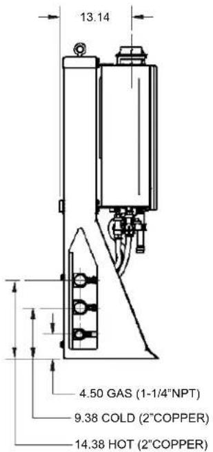
text_image
13.14 4.50 GAS (1-1/4"NPT) 9.38 COLD (2"COPPER) 14.38 HOT (2"COPPER)FRONT

text_image
44.00 20.50 5.92 TYP 57.69BACK

text_image
1.00 27.44 2.00 38.53
text_image
34.53 16.78 18.00BOTTOM
| Model | Configuration | Illustration |
| TRW02 |  |  |
Specifications
| 2 UNIT WALL MOUNT FRAME | |
| Model | TRS02ILW |
| Water Heater Model | C199i, C199e (NG/LP) |
| Crate Dimensions (HxLxD) - in 66 x 67 x 35 | |
| Weight - Fully Assembled - lbs | 204 |
| Weight - Shipping (total) - lbs | 400 |
| Rack Frame - Specifications | |
| Frame Rail Type | Sheet Metal |
| Frame Material Aluminum (0.090 5052-H32) | |
| Frame Finish | Powder Coat |
| Color | Gray |
| Water & Gas Connections | |
| Hot Water Trunk Line Diameter 2" | |
| Cold Water Trunk Line Diameter 2" | |
| Hot Water Trunk Line Material Rigid Copper | |
| Cold Water Trunk Line Material Rigid Copper | |
| Water Trunk Connection Type 2" PIPE | |
| Gas Trunk Line Diameter 1-1/4" | |
| Gas Trunk Connection Type 1-1/4" MNPT | |
| Gas Trunk Line Material Sch 40 Steel | |
| Gas Branch Line Material PVC Over CSST | |
| Electric Requirements | |
| Voltage | AC 120 Volts—60 Hz |
| Maximum Current (Amperes) | 8 |
| BTU and Flow Rates for C199i, C199e (NG/LP) | |
| Number of Tankless Water Heaters | 2 |
| Flow rate @ 70°F rise (gpm) | 10.8 |
| Flow rate @ 100°F rise (gpm) | 7.6 |
| Minimum input rate (Btuh) | 15,200 |
| Maximum input rate (Btuh) | 398,000 |
natural_image
3D rendering of two large industrial tanks mounted on a metal frame with pipes and valves (no visible text or symbols)3 UNIT WALL MOUNT FRAME
LEFT

text_image
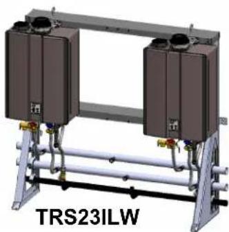
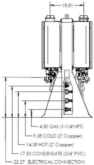
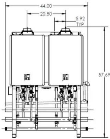
13.16 4.50 GAS (1-1/4" NPT) 9.38COLD (2" Copper) 14.38 HOT (2"COPPER) 17.50 CONDENSATE (3/4" PVC) 22.27 Electrical ConnectionFRONT
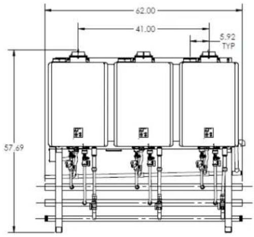
text_image
62.00 41.00 5.92 TYP 57.69BACK
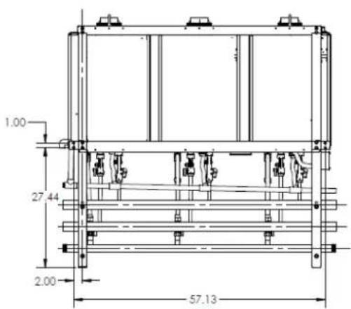
text_image
1.00 27.44 2.00 57.13
text_image
53.13 16.79 18.01BOTTOM
| Model Configuration Illustration | ||
| TRS03ILW | - - 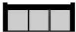 | 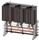 |
| TRS23ILW |  |  |
Specifications
| 3 UNIT WALL MOUNT FRAME | ||
| Model | TRS03ILW | TRS23ILW |
| Water Heater Model | C199i, C199e (NG/LP) | |
| Crate Dimensions (HxLxD) - in 66 x 67 x 35 | ||
| Weight - Fully Assembled - lbs | 291 | 218 |
| Weight - Shipping (total) - lbs | 487 | 414 |
| Rack Frame - Specifications | ||
| Frame Rail Type | Sheet Metal | |
| Frame Material | Aluminum (0.090 5052-H32) | |
| Frame Finish | Powder Coat | |
| Color | Gray | |
| Water, Gas, and Condensate Connections | ||
| Hot Water Trunk Line Diameter 2" | ||
| Cold Water Trunk Line Diameter 2" | ||
| Hot Water Trunk Line Material Rigid Copper | ||
| Cold Water Trunk Line Material Rigid Copper | ||
| Water Trunk Connection Type 2" PIPE | ||
| Gas Trunk Line Diameter 1-1/4" | ||
| Gas Trunk Connection Type 1-1/4" MNPT | ||
| Gas Trunk Line Material Sch 40 Steel | ||
| Gas Branch Line Material PVC Over CSST | ||
| Condensate Trunk Line Diameter | 3/4" | N/A |
| Condensate Trunk Line Material | Sch-40 PVC | N/A |
| Condensate Trunk Connection Type | 3/4" Pipe | N/A |
| Electric Requirements | ||
| Prewired Electrical Assembly | Yes (Indoor Models Only) | N/A |
| Voltage | AC 120 Volts—60 Hz | |
| Maximum Current (Amperes) | 12 | 8 |
| BTU and Flow Rates for C199i, C199e (NG/LP) | ||
| Number of Tankless Water Heaters | 3 | 2 |
| Flow rate @ 70°F rise (gpm) | 16.2 | 10.8 |
| Flow rate @ 100°F rise (gpm) | 11.4 | 7.6 |
| Minimum input rate (Btuh) | 15,200 | 15,200 |
| Maximum input rate (Btuh) | 597,000 | 398,000 |
natural_image
3D rendering of a three-tier industrial control unit with copper pipes and valves (no text or symbols visible)23 Rinnai Rack Installation
natural_image
3D rendering of a mechanical assembly with two vertical chambers mounted on a metal frame, labeled 'TRS23ILW' below (no other text or symbols visible)4 UNIT FREE STANDING FRAME
LEFT
text_image
18.81 4.50 GAS (1-1/4"NPT) 9.38 COLD (2" Copper) 14.38 HOT (2" Copper) 17.50 CONDENSATE (3/4" PVC) 22.27 ELECTRICAL CONNECTIONFRONT
text_image
44.00 20.50 5.92 TYP 57.69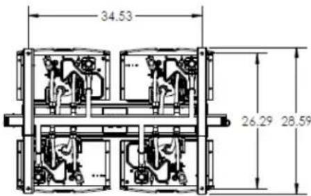
text_image
34.53 26.29 28.59BOTTOM
| Model | Configuration | Illustration | |
| TRS04 |  | 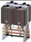 | |
| TRS03 |  | 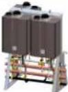 | |
| TRS02IL | Inline (facing same direction) |  | 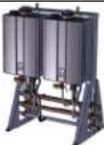 |
| TRS02 | Back to Back |  | 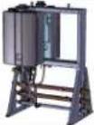 |
Specifications
| 4 UNIT FREE STANDING FRAME | ||||
| Model | TRS04 | TRS03 | TRS02 | TRS02IL |
| Water Heater Model | C199i, C199e (NG/LP) | |||
| Crate Dimensions (HxLxD) - in 66 x 57 x 35 | ||||
| Weight - Fully Assembled - Ibs | 357 | 284 | 210 | 208 |
| Weight - Shipping (total) - Ibs | 553 | 480 | 406 | 404 |
| Rack Frame - Specifications | ||||
| Frame Rail Type | Sheet Metal | |||
| Frame Material | Aluminum (0.090 5052-H32) | |||
| Frame Finish | Powder Coat | |||
| Color | Gray | |||
| Water & Gas Connections | ||||
| Hot Water Trunk Line Diameter | 2" | |||
| Cold Water Trunk Line Diameter | 2" | |||
| Hot Water Trunk Line Material Rigid Copper | ||||
| Cold Water Trunk Line Material | Rigid Copper | |||
| Water Trunk Connection Type | 2" PIPE | |||
| Gas Trunk Line Diameter | 1-1/4" | |||
| Gas Trunk Connection Type | 1-1/4" MNPT | |||
| Gas Trunk Line Material | Sch 40 Steel | |||
| Gas Trunk Branch Line Material | PVC Over CSST | |||
| Condensate Trunk Line Diameter | 3/4" | N/A | ||
| Condensate Trunk Material | Sch-40 PVC | N/A | ||
| Condensate Trunk Connection Type | 3/4" Pipe | N/A | ||
| Electric Requirements | ||||
| Prewired Electrical Assembly | Yes (Indoor Models Only) | N/A | ||
| Voltage | AC 120 Volts—60 Hz | |||
| Maximum Current (Amperes) | 16 | 12 | 8 | |
| BTU and Flow Rates for C199i, C199e (NG/LP) | ||||
| Number of Tankless Water Heaters | 4 | 3 | 2 | |
| Flow rate @ 70°F rise (gpm) | 21.6 | 16.2 | 10.8 | |
| Flow rate @ 100°F rise (gpm) | 15.2 | 11.4 | 7.6 | |
| Minimum input rate (Btuh) | 15,200 | |||
| Maximum input rate (Btuh) | 796,000 | 597,000 | 398,000 | |
natural_image
3D rendering of a mechanical or electrical device with multiple ports and pipes (no visible text or symbols)TRS04
25 Rinnai Rack Installation

natural_image
3D rendering of a dual-chamber industrial vessel with heat exchangers and pipes (no text or symbols visible)TRS03

natural_image
3D rendering of a mechanical device with no visible text or symbolsTRS02
natural_image
Industrial equipment setup with two large cylindrical tanks and a metal frame (no visible text or symbols)TRS02IL
Specifications
6 UNIT FREE STANDING FRAME
LEFT
text_image
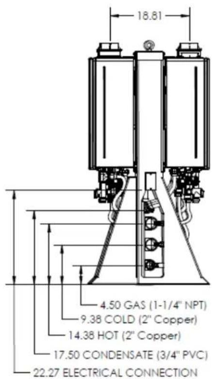
18.81 4.50 GAS (1-1/4" NPT) 9.38 COLD (2" Copper) 14.38 HOT (2" Copper) 17.50 CONDENSATE (3/4" PVC) 22.27 ELECTRICAL CONNECTIONFRONT
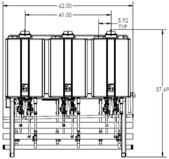
text_image
62.00 41.00 5.92 TYP 57.69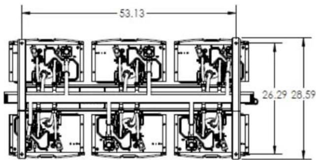
text_image
53.13 26.29 28.59BOTTOM
| Model | Configuration | Illustration |
| TRS06 |  |  |
| TRS05 |  | 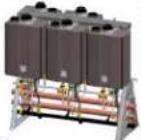 |
| TRS03IL |  | 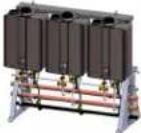 |
Specifications
| 6 UNIT FREE STANDING FRAME | ||||||
| Model | TRS06 | TRS05 | TRS46 | TRS36 | TRS03IL | TRS23IL |
| Water Heater Model C199i, C199e (NG/LP) | ||||||
| Crate Dimensions (HxLxD) - in 66 x 67 x 35 | ||||||
| Weight - Fully Assembled - Ibs | 526 | 452 | 378 | 284 | 284 | 210 |
| Weight - Shipping (total) - Ibs | 722 | 649 | 576 | 480 | 480 | 406 |
| Rack Frame - Specifications | ||||||
| Frame Rail Type | Sheet Metal | |||||
| Frame Material | Aluminum (0.090 5052-H32) | |||||
| Frame Finish | Powder Coat | |||||
| Color | Gray | |||||
| Water & Gas Connections | ||||||
| Hot Water Trunk Line Diameter | 2-1/2" | 2" | ||||
| Cold Water Trunk Line Diameter | 2-1/2" | 2" | ||||
| Hot Water Trunk Line Material | Rigid Copper | |||||
| Cold Water Trunk Line Material | Rigid Copper | |||||
| Water Trunk Connection Type | 2-1/2" PIPE | 2" PIPE | ||||
| Gas Trunk Line Diameter | 1-1/2" | 1-1/4" | ||||
| Gas Trunk Connection Type | 1-1/2" MNPT | 1-1/4"MNPT | ||||
| Gas Trunk Line Material | Sch 40 Steel | |||||
| Gas Branch Line Material | PVC Over CSST | |||||
| Condensate Trunk Line Diameter | 3/4" | N/A | ||||
| Condensate Trunk Line Material | Sch-40 PVC | N/A | ||||
| Condensate Trunk Connection Type | 3/4" Pipe | N/A | ||||
| Electric Requirements | ||||||
| Prewired Electrical Assembly | Yes (Indoor Models Only) | N/A | ||||
| Voltage | AC 120 Volts—60 Hz | |||||
| Max Current (Amperes) | 24 | 20 | 16 | 12 | 12 | 8 |
| BTU and Flow Rates for C199i, C199e (NG/LP) | ||||||
| Number of Tankless Water Heaters | 6 | 5 | 3 | 4 | 2 | |
| Flow rate @ 70°F rise (gpm) | 32.4 | 27.0 | 16.2 | 21.6 | 10.8 | |
| Flow rate @ 100°F rise (gpm) | 22.8 | 19.0 | 11.4 | 15.1 | 7.6 | |
| Minimum input rate (Btuh) | 15,200 | |||||
| Maximum input rate (Btuh) | 1,194,000 | 995,000 | 597,000 | 796,000 | 398,000 | |

natural_image
3D rendering of a multi-chamber electrical enclosure with copper and gold pipes (no text or symbols visible)TRS06
natural_image
3D rendering of a multi-chamber industrial or electrical enclosure with pipes and control panels (no visible text or symbols)TRS05
natural_image
Industrial electrical enclosure with three cylindrical tanks and a multi-tiered red and brown components (no visible text or symbols)TRS03IL
natural_image
3D rendering of a mechanical assembly with cylindrical components and a coiled spring (no text or symbols visible)TRS36

natural_image
3D mechanical assembly diagram showing two blocks with internal components and a coiled spring (no text or symbols)TRS46
natural_image
3D rendering of a mechanical assembly with two vertical cylindrical components mounted on a metal frame (no text or symbols visible)TRS23IL
27 Rinnai Rack Installation
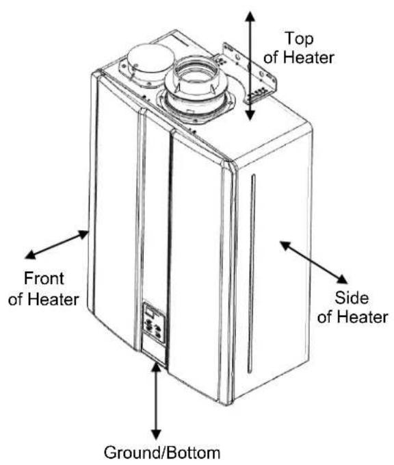
Clearances
Install the rack system so that the clearances shown below are followed.
text_image
Top of Heater Front of Heater Side of Heater Ground/BottomIndoor models: RUC98i, C199i, RUR98i
| to Combustibles inches (mm) | to Non-Combustibles inches (mm) | |
| Top of Heater | 6 * (152) 2 * (51) | |
| Back of Heater | 0 (zero) 0 (zero) | |
| Front of Heater | 6 (152) 6 (152) | |
| Sides of Heater | 2 (51) 1/2 (13) | |
| Ground/Bottom | 12 (305) 12 (305) | |
| Vent | 0 (zero) 0 (zero) | |
* 0 inches from vent components and condensate drain line.
The clearance for servicing is 24 inches in front of the water heater.
For closet installation, clearance is 6 inches (152 mm from the front.

text_image
are renewed. Top of Heater Front of Heater Side of Heater Ground/BottomThe clearance for servicing is 24 inches in front of the water heater.
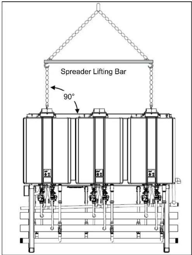
Hoisting (Lifting Lugs)
Lugs are installed on the top side of the following racks for hoisting and moving. The lines or cables to the lugs should be at a 90° angle. Use a spreader lifting bar to hoist these racks.
Weights of the complete assemblies are available in the Specifications section of this manual.
NOTE: DO NOT hoist the crate or palette.
MODELS AVAILABLE WITH LIFTING LUGS
Hoisting (Straps)
For the TRW02 and TRW03 wall hanging racks, use hoisting straps looped around the top frame.
Weights of the complete assemblies are available in the Specifications section of this manual.
NOTE: DO NOT hoist the crate or palette.


text_image
Spreader Lifting Bar 90°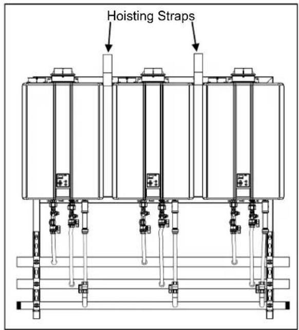
text_image
Hoisting StrapsSecuring Free Standing Racks
All mechanical components shall be anchored and installed in accordance with national and/or local codes having jurisdiction. Base holes to secure all free standing TRS are 0.563 inches in diameter. Reference local codes regarding minimum concrete thickness and use appropriate expansion anchors that is capable of supporting the TRS weight or where installation is outdoor, anchors should be capable supporting the TRS weight and wind shear. Reference and follow anchor manufacturer's use and installation requirements.
FREE STANDING MODELS AVAILABLE
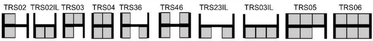
text_image
TRS02 TRS02IL TRS03 TRS04 TRS36 TRS46 TRS23IL TRS03IL TRS05 TRS06
text_image
Bottom view of free standing racks. (Flex line illustrations have been removed for clarity) Ø 0.563 (4) Plcs 28.50 26.29 36.53 34.51 55.11 53.09 Ø 0.563 (4) Plcs 28.50 26.29Securing Wall Mount Racks (ILW)

WARNING
THE WALL MUST BE CABABLE OF CARRYING THE OPERATING WEIGHT OF THE INSTALLED TRS SYSTEM. CONSULT A STRUCTURAL ENGINEER FOR STRUCTURAL
ANALYSIS OF THE WALL AND APPROPRIATE HANGING METHODS BEFORE ATTEMPTING TO HANG THE TRS SYSTEM. FAILURE TO COMPLY WITH THE ABOVE REQUIREMENT COULD RESULT IN SUBSTANTIAL PROPERTY DAMAGE, SEVERE PERSONAL INJURY OR DEATH.
• Identify the installation location and confirm that the installation will meet all required clearances.
- The size and embedment specified are for anchors installed in stone or aggregate concrete only, for other anchorage details the contractor or engineer on record for the building shall consult with a licensed structural engineer for all anchorage of equipment not called out in this manual.
- In the event of a conflict or inconsistency between items indicated in this manual regarding code requirements, the more stringent standard shall prevail.
WALL RACK MODELS AVAILABLE
TRS02ILW, TRS03ILW, & TRS23ILW
- Using the holes in the wall bracket, Securely attach the rack to the wall. Ensure that the attachment strength is sufficient.
- Reference local codes regarding minimum concrete thickness and use appropriate expansion anchors that is capable supporting the TRS weight.
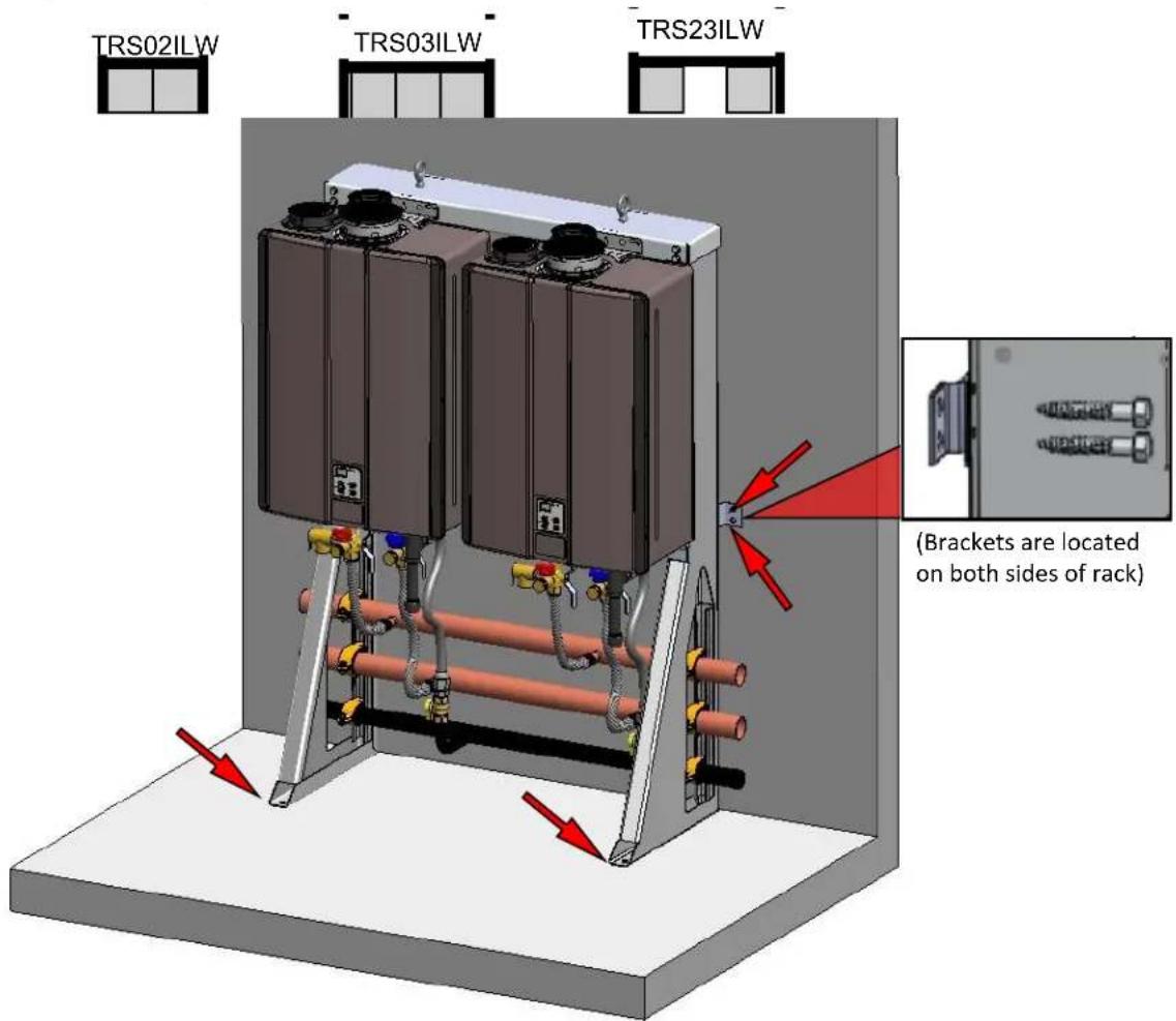
text_image
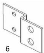
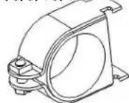
TRS02ILW TRS03ILW TRS23ILW (Brackets are located on both sides of rack)Securing Wall Hanging Racks (TRW)
WARNING
THE WALL MUST BE CABABLE OF CARRYING THE OPERATING WEIGHT OF THE INSTALLED TRS SYSTEM. CONSULT A STRUCTURAL ENGINEER FOR STRUCTURAL
ANALYSIS OF THE WALL AND APPROPRIATE HANGING METHODS BEFORE ATTEMPTING TO HANG THE TRS SYSTEM. FAILURE TO COMPLY WITH THE ABOVE REQUIREMENT COULD RESULT IN SUBSTANTIAL PROPERTY DAMAGE, SEVERE PERSONAL INJURY OR DEATH.
• Identify the installation location and confirm that the installation will meet all required clearances.
- In the event of a conflict or inconsistency between items indicated in this manual regarding code requirements, the more stringent standard shall prevail.
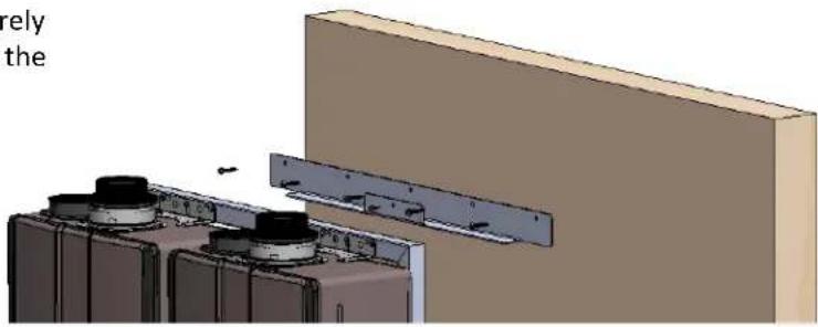
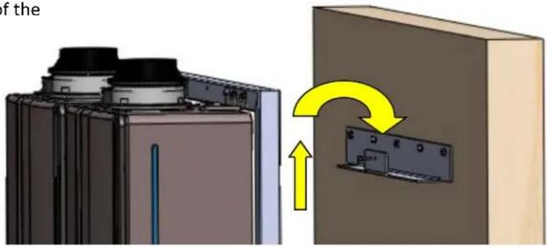
TRW02, TRW03, TRW23, TRW02SE, TRW02ST, TRW03ST
- Using the holes in the wall hanging bracket, Securely attach the bracket level to the wall. Ensure that the attachment strength is sufficient.
natural_image
3D mechanical assembly diagram showing two components mounted on a wall with mounting brackets (no text or symbols visible)- Lift the wall hanging rack, and insert the top of the frame into the bracket.
text_image
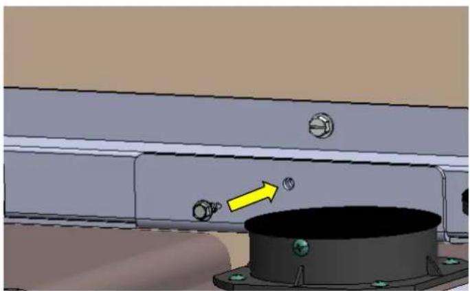
if the ↑- Secure the front of the bracket to the front of the wall hanging frame with a #12 X 3/4 drill point screw.
natural_image
3D mechanical assembly diagram showing a component with bolts and a yellow arrow pointing to a circular feature (no text or symbols)Securing Wall Hanging Racks (TRC)
WARNING
THE WALL MUST BE CABABLE OF CARRYING THE OPERATING WEIGHT OF THE INSTALLED TRS SYSTEM. CONSULT A STRUCTURAL ENGINEER FOR STRUCTURAL
ANALYSIS OF THE WALL AND APPROPRIATE HANGING METHODS BEFORE ATTEMPTING TO HANG THE TRS SYSTEM. FAILURE TO COMPLY WITH THE ABOVE REQUIREMENT COULD RESULT IN SUBSTANTIAL PROPERTY DAMAGE, SEVERE PERSONAL INJURY OR DEATH.
• Identify the installation location and confirm that the installation will meet all required clearances.
- In the event of a conflict or inconsistency between items indicated in this manual regarding code requirements, the more stringent standard shall prevail.
TRC02
- Using the holes in the wall hanging brackets, Secure-ly attach the brackets level to the wall. Ensure that the attachment strength is sufficient. Brackets are to be installed within 1/2" from the corner.
natural_image
3D architectural rendering of a room with two wall-mounted appliances and a metal shelf assembly (no text or symbols visible)- Lift the corner hanging rack, and insert the top of the frame into the two brackets.

natural_image
3D diagram of a battery mounting structure with yellow directional arrows indicating flow or movement (no text or symbols present)- Secure the frame to the hanging brackets using two, 12-14 Thread, 2-1/2" long, drill point screws (Supplied). Fastener head is 5/16" hex.

natural_image
3D mechanical assembly diagram showing pipe connections and mounting brackets (no text or symbols)Relief Valve Piping
Each Rinnai tankless water heater on the TRS comes installed with Isolation valves and a pressure relief valve.
Refer to the installation and operation manual for more information on proper piping for the relief valve drain.

text_image
Pressure Relief Valve Isolation ValvePiping for Multiple Racks
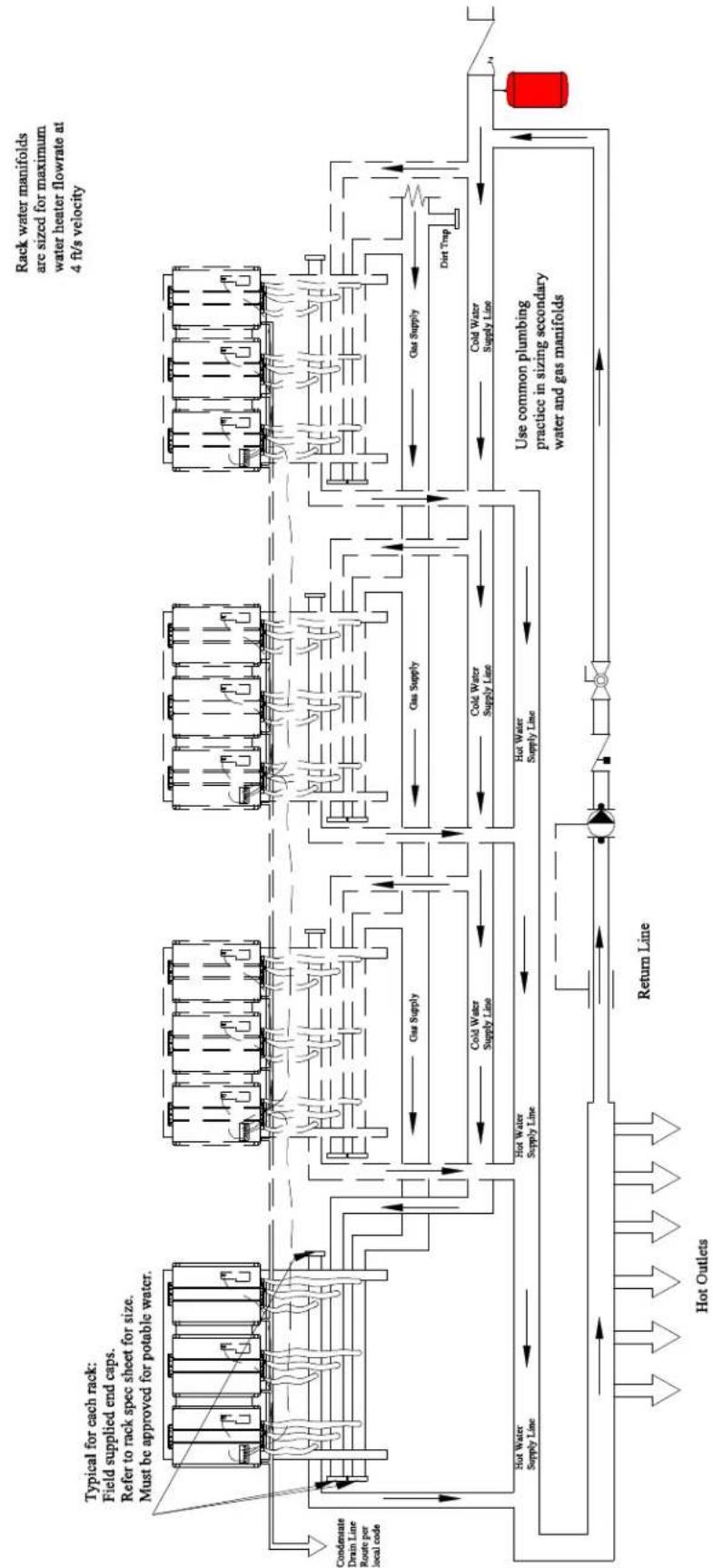
Multiple rack systems should be installed in parallel using a secondary manifold from the building cold and hot water supply. Reference the drawing on the following page for guidance on plumbing multiple racks in a parallel piping system.
A low pressure gas regulator must be installed prior to the rack system. Note the maximum cumulative input for the system when sizing the gas regulator.
Use common plumbing practice and reference all applicable codes when sizing the secondary manifolds and gas regulator.
Condensing Tankless
Rack Parallel Piping System
flowchart
graph TD
    A["Condensate Drain Line Route per local code"] --> B["Hot Water Supply Line"]
    B --> C["Return Line"]
    C --> D["Hot Outlets"]
    D --> E["Hot Water Supply Line"]
    E --> F["Cold Water Supply Line"]
    F --> G["Gas Supply"]
    G --> H["Cold Water Supply Line"]
    H --> I["Use common plumbing practice in sizing secondary water and gas manifolds"]
    I --> J["Dirt Trap"]
    J --> K["Gas Supply"]
    K --> L["Cold Water Supply Line"]
    L --> M["Cold Water Supply Line"]
    M --> N["Gas Supply"]
    N --> O["Cold Water Supply Line"]
    O --> P["Dirt Trap"]
    P --> Q["Gas Supply"]
    Q --> R["Cold Water Supply Line"]
    R --> S["Cold Water Supply Line"]
    S --> T["Cold Water Supply Line"]
    T --> U["Cold Water Supply Line"]
    U --> V["Cold Water Supply Line"]
    V --> W["Cold Water Supply Line"]
    W --> X["Cold Water Supply Line"]
    X --> Y["Cold Water Supply Line"]
    Y --> Z["Cold Water Supply Line"]
    Z --> AA["Cold Water Supply Line"]
    AA --> AB["Cold Water Supply Line"]
    AB --> AC["Cold Water Supply Line"]
    AC --> AD["Cold Water Supply Line"]
    AD --> AE["Cold Water Supply Line"]
    AE --> AF["Cold Water Supply Line"]
    AF --> AG["Cold Water Supply Line"]
    AG --> AH["Cold Water Supply Line"]
    AH --> AI["Cold Water Supply Line"]
    AI --> AJ["Cold Water Supply Line"]
    AJ --> AK["Cold Water Supply Line"]
    AK --> AL["Cold Water Supply Line"]
    AL --> AM["Cold Water Supply Line"]
    AM --> AN["Cold Water Supply Line"]
    AN --> AO["Cold Water Supply Line"]
    AO --> AP["Cold Water Supply Line"]
    AP --> AQ["Cold Water Supply Line"]
    AQ --> AR["Cold Water Supply Line"]
    AR --> AS["Cold Water Supply Line"]
    AS --> AT["Cold Water Supply Line"]
    AT --> AU["Cold Water Supply Line"]
    AU --> AV["Cold Water Supply Line"]
    AV --> AW["Cold Water Supply Line"]
    AW --> AX["Cold Water Supply Line"]
    AX --> AY["Cold Water Supply Line"]
    AY --> AZ["Cold Water Supply Line"]
    AZ --> BA["Cold Water Supply Line"]
    BA --> BB["Cold Water Supply Line"]
    BB --> BC["Cold Water Supply Line"]
    BC --> BD["Cold Water Supply Line"]
    BD --> BE["Cold Water Supply Line"]
    BE --> BF["Cold Water Supply Line"]
    BF --> BG["Cold Water Supply Line"]
    BG --> BH["Cold Water Supply Line"]
    BH --> BI["Cold Water Supply Line"]
    BI --> BJ["Cold Water Supply Line"]
    BJ --> BK["Cold Water Supply Line"]
    BK --> BL["Cold Water Supply Line"]
    BL --> BM["Cold Water Supply Line"]
    BM --> BN["Cold Water Supply Line"]
    BN --> BO["Cold Water Supply Line"]
    BO --> BP["Cold Water Supply Line"]
    BP --> BQ["Cold Water Supply Line"]
    BQ --> BR["Cold Water Supply Line"]
    BR --> BS["Cold Water Supply Line"]
    BS --> BT["Cold Water Supply Line"]
    BT --> BU["Cold Water Supply Line"]
    BU --> BV["Cold Water Supply Line"]
    BV --> BW["Cold Water Supply Line"]
    BW --> BX["Cold Water Supply Line"]
    BX --> BYC["Cold Water Supply Line"]
    BYC --> BZ["Cold Water Supply Line"]
    BZ --> CA["Cold Water Supply Line"]
    CA --> CB["Cold Water Supply Line"]
    CB --> CC["Cold Water Supply Line"]
    CC --> CD["Cold Water Supply Line"]
    CD --> DEC["Cold Water Supply Line"]
    DEC --> DF["Cold Water Supply Line"]
    DF --> DG["Return Line"]
Ghosted units are potential supplemental banks of tankless racks
| This is not an engineering drawing; It is Intended only as a guide and not as a replacement for professional engineering project drawings, This drawing is not Intended to describe a complete system. It is up to the contractor or engineer to determine the necessary components and configuration of the particular system to be installed. The drawing does not imply compliance with local building code requirements. It is the responsibility of the engineer or contractor to ensure that the installation is in accordance with all local building codes, Confer with local building officials before Installation. | Rinnai America Corporation103 International DrivePeachtree City, GA 302691-800-621-9419 | This drawing is the exclusive property of Rinnai America Corporation, it may not be reproduced or given to third parties. | ||||
| Condensing TanklessRack Parallel Piping System | ||||||
| Tolerance Fraction =±1/15x,x=±0.030x,xx=±0.015x,xxx=±0.005 | Shawn By DRM | SIZEA | SCALENTS | DNC NO.RPPS | REV.D | |
| Approved By RS | DATE 07/23/12 | SHEET 1 of 1 | ||||
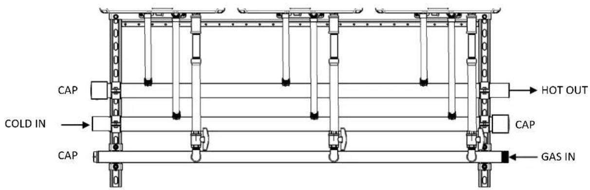
End Caps / Connections
End caps are to be field supplied and to be of the following materials:
• Cold water cap - Brass or Copper
• Hot water cap - Brass or Copper
Gas cap - black iron
Once flow direction and gas supply side is determined the other (opposite) side of the manifold must be capped. See the example below.
Leak check the capped ends of the manifolds.
text_image
CAP COLD IN CAP HOT OUT CAP GAS INCondensate Drain
Each Rinnai tankless water heater has a condensate drain outlet on the bottom of the unit. A drain line must be connected to each water heater.
Freestanding rack systems with 3 or more units will include a prefabricated condensate manifold. For all other rack systems, a condensate drain manifold must be field fabricated (not shown in diagram)
Condensate piping shall be CPVC or PVC material and shall not be smaller than the drain connection on the appliance.
Components of the condensate drainage shall be CPVC or PVC material. All components shall be selected for the pressure and temperature rating of the installation.
Where the drain pipes from more than one unit are manifolded together for condensate drainage, the pipe or tubing shall be sized in accordance with an approved method as dictated by local codes.
Condensate must be disposed of according to local codes.
Piping Diagram for Basic Installation
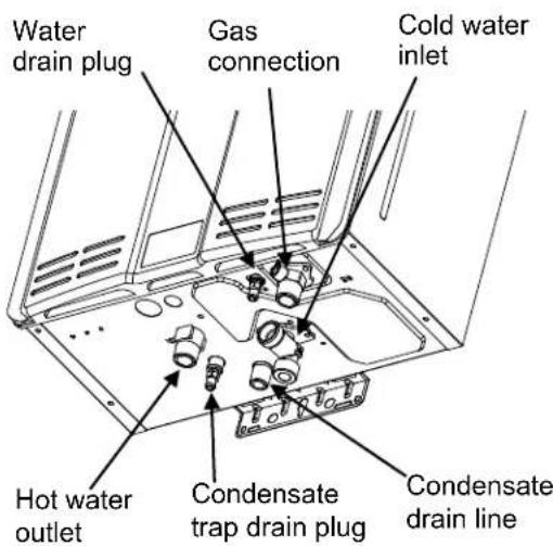
text_image
Water drain plug Gas connection Cold water inlet Hot water outlet Condensate trap drain plug Condensate drain lineThe condensate drain pipe (along its entire length) must be at least the same diameter as the drain line.
Condensate Manifold
Condensate Manifolds are installed above the water manifolds of the following racks for single point condensate connection.
MODELS AVAILABLE WITH CONDENSATE MANIFOLDS:

text_image
TRS03ILW TRS03IL TRS03 TRS04 TRS36 TRS46 TRS05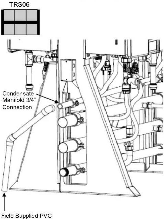
text_image
TRS06 Condensate Manifold 3/4" Connection Field Supplied PVCCondensate drain must be sloped downward from the rack system. Condensate must be disposed of per local codes.
NOTICE
The telescoping fitting on the capped side of the condensate manifold is for air relief. DO NOT plug the opening.
Checklist for Plumbing
☐ Purge the water line of all debris and air by closing the hot isolation valve and opening the cold isolation valve and its drain. Debris will damage the water heater. Use a bucket or hose if necessary.
☐ Ensure that hot and cold water lines are not crossed to the unit and are leak free.
☐ Ensure that a pressure relief valve is installed with a rating that exceeds the BTU input of the water heater model. Refer to the rating plate on the side of the water heater for BTU input.
☐ Clean the inlet water filter by closing the cold and hot water inlet isolation (shut-off) valves. Put a bucket under the filter at the bottom of the water heater to catch any water that is contained inside the unit. Unscrew the water filter. Rinse the filter to remove any debris. Install the filter and open the isolation valves.
☐ Check for proper water pressure to the water heater. Minimum water pressure is 50 psi. Rinnai recommends 60-80 psi for maximum performance.
☐ Ensure any issues regarding water quality have been properly addressed.
Installation of Gas Supply
WARNING
- A licensed professional must install the gas supply.
- Turn off 120v power supply.
- Turn off the gas.
- Gas is flammable. Do not smoke or provide other ignition sources while working with gas.
- Do not turn on the water heater or gas until all fumes are gone.
MUST DO
- Check the type of gas and the gas inlet pressure before connecting the water heater. If the water heater is not of the gas type that the building is supplied with, DO NOT connect the water heater. Contact the dealer for the proper unit to match the gas type.
- Check the gas supply pressure immediately upstream at a location provided by the gas company. Supplied gas pressure must be within the limits shown in the Specifications section of this manual with all gas appliances operating.
- Before placing the appliance in operation, all joints including the heater must be checked for gas tightness by means of leak detector solution, soap and water, or an equivalent nonflammable solution, as applicable. (Since some leak test solutions, including soap and water, may cause corrosion or stress cracking, the piping shall be rinsed with water after testing, unless it has been determined that the leak test solution is non-corrosive.)
- Use approved connectors to connect the unit to the gas line. Purge the gas line of any debris before connection to the water heater.
- Any compound used on the threaded joint of the gas piping shall be a type that resists the action of liquefied petroleum gas (propane / LPG).
- The gas supply line shall be gas tight, sized, and so installed as to provide a supply of gas sufficient to meet the maximum demand of the heater and all other gas consuming appliances at the location without loss of pressure.
INFORMATION
- If in doubt about the size of the gas line, refer to an approved pipe sizing chart
Connect Electricity

WARNING
Do not use an extension cord or an adapter plug with this appliance.
The water heater must be electrically grounded in accordance with local codes and ordinances or, in the absence of local codes, in accordance with the National Electrical Code, ANSI/NFPA No. 70.
Indoor water heaters are equipped with a three-prong (grounding) plug for your protection against shock hazard and should be plugged directly into a properly grounded three-prong receptacle. Do not cut or remove the grounding terminal from this plug.
Do not rely on the gas or water piping to ground the water heater. A screw is provided in the junction box for the grounding connection.
The water heater requires 120 VAC, 60 Hz power from a properly grounded circuit.
If using the 5 foot long power cord, plug it into a standard 3 prong 120 VAC, 60 Hz properly grounded wall outlet.
On outdoor models, a disconnect switch must be provided and installed for the incoming 120 VAC power. It should be a type that is suitable for outdoor use. Check the National Electrical Code, ANSI/NFPA 70 and your local codes for a proper switch type to use in your area.
The wiring diagram is located on the Technical Sheet attached to the inside of the front cover.
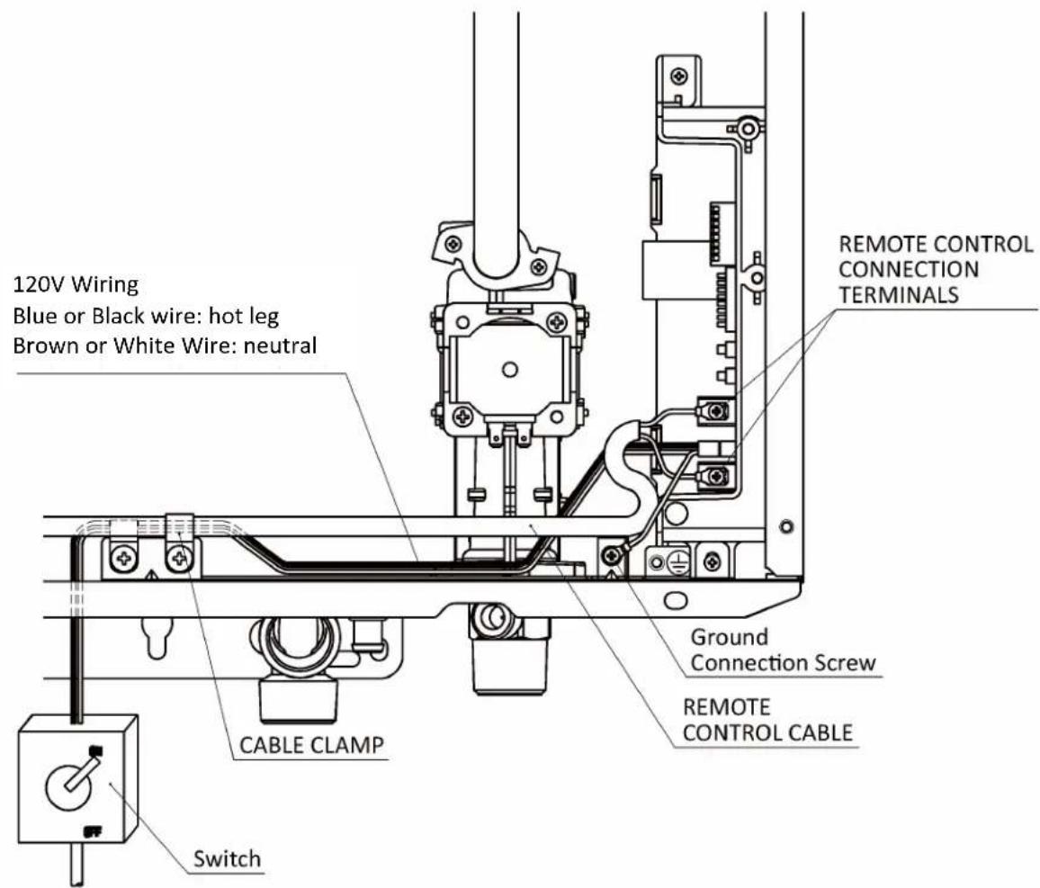
text_image
120V Wiring Blue or Black wire: hot leg Brown or White Wire: neutral CABLE CLAMP Switch REMOTE CONTROL CONNECTION TERMINALS Ground Connection Screw REMOTE CONTROL CABLEElectrical (Pre-wired electrical assembly)
Electrical Assemblies are installed on the middle rack frame of the following indoor racks for single point electrical connection.
IMPORTANT: Refer to the Specifications sections in this manual for electrical requirements.
INTERIOR MODELS AVAILABLE WITH ELECTRICAL ASSEMBLIES:

text_image
4 Unit Electrical Assembly with (2) 20A, 125V, 2-Pole, 3 Wire Grounding Receptacles. TRS03ILW TRS03IL TRS03 TRS04 TRS36 TRS46
text_image
6 Unit Electrical Assembly with (3) 20A, 125V, 2-Pole, 3 Wire Grounding Receptacles. TRS05 TRS06WARNING
Shut off building supply power prior to connecting to TRS electrical assembly. Failure to do so may result in property damage, bodily harm, or death.

text_image
Conduit Punch-out Green (Ground) White (Neutral) Black (Hot)- Locate gang box on side of TRS frame.
- Remove the 2 screws securing front panel to gang box.
- Remove front panel.
- Run building supplied electrical wiring and conduit to gang box.
- Connect building wiring to the 3 12AWG, THHN wires, Hot (Black), Neutral (White), and Ground (Green).
- Reinstall front panel to gang box using 2 screws.
Electrical (Pre-wired electrical assembly)
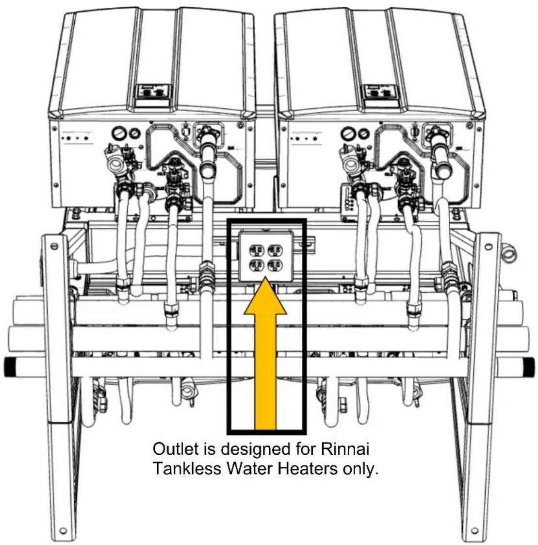
- Once the building electrical power supply has been wired to the rack system, plug the indoor units into the outlet located under the center rack frame as shown below.
IMPORTANT: The outlet is designed for use with Rinnai Tankless Water Heaters only. Do not insert power cords belonging to other appliances or electrical sources into the outlet.
text_image
Outlet is designed for Rinnai Tankless Water Heaters only.
NOTICE

DO NOT connect the tankless water heaters to the outlet located under the center rack prior to connecting building power supply to the rack electrical gang box. Doing so may cause damage to the PC Boards of the tankless water heaters.
TRW ST Series Dedicated Return Plumbing Instructions
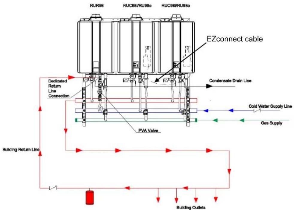
All TRW ST Series racks are set up for a dedicated recirculation return line. A single return line will connect to the RUR98 unit above the cold isolation valve as shown in the below schematic. For the TRW03ST with multiple RUC98 units, the units must be connected using an EZconnect cable.
flowchart
graph TD
    A["RUR98"] --> B["Dedicated Return Line Connection"]
    B --> C["PVA Valve"]
    C --> D["Building Return Line"]
    D --> E["Building Outlets"]
    F["RUC98/RU98a"] --> G["Condensate Drain Line"]
    G --> H["Cold Water Supply Line"]
    H --> I["Gas Supply"]
    J["EZconnect cable"] --> K["Consonator"]
    style A fill:#f9f,stroke:#333
    style F fill:#f9f,stroke:#333
    style J fill:#f9f,stroke:#333

text_image
RUR98 RUC98 RUC98 Dedicated return line connection 3/4" FNPT Unscrew the square head threaded plug to connect the building dedicated recircu- lation return line. WARNING: Make sure the water supply is off and the system is depressurized.42 Rinnai Rack Installation
TRW ST Series Crossover Return Conversion Instructions
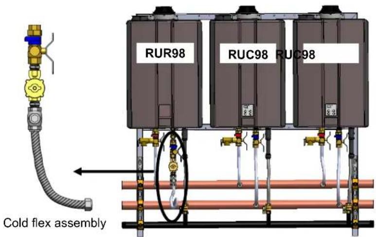
To use a crossover valve for recirculation, the PVA and check valve must be removed from the RUR98 unit and replaced with a cold water flex line. A PVA must be added to the RUC98 units. For a TRW02ST, the cold line flex for the RUR98 can be removed from the RUC unit. You will then remove the check valve from the flex line assembly from the RUR98 and add it to the RUC unit. For applications with a TRW03ST, Kit 104000278 must be purchased to add a PVA valve and threaded nipple to the second RUC unit.

flowchart
graph TD
    A["Condensate Drain Line"] --> B["RUR98"]
    A --> C["RUC98i/RU98e"]
    A --> D["RUC98i/RU98e"]
    B --> E["PVA Valve"]
    C --> E
    D --> E
    E --> F["Cold Water Supply Line"]
    E --> G["Gas Supply"]
    H["FURTHEST FIXTURE"] --> I["CROSSOVER VALVE"]
    I --> J["Hot Water Supply Line"]
For conversion to crossover recirculation, follow the steps below.
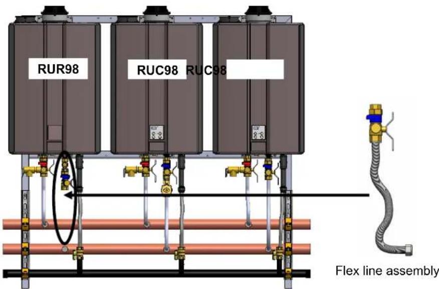
- Remove the cold flex assembly from the RUR98 unit.
text_image
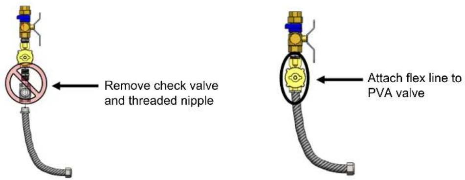
RUR98 RUC98 RUC98 Cold flex assembly- Remove the check valve and threaded nipple from the assembly and re-attach the flex line to the PVA valve.
text_image
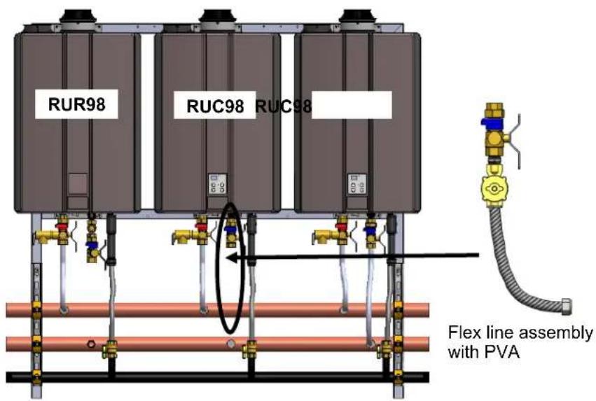
Remove check valve and threaded nipple Attach flex line to PVA valve- Remove the cold flex assembly from an RUC98 unit.

text_image
RUR98 RUC98 RUC98 Cold flex assembly- Install the flex line assembly with the PVA from step 2 onto the RUC98 unit.
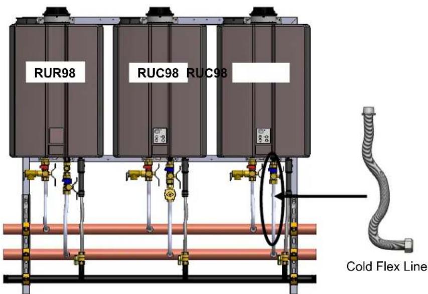
text_image
RUR98 RUC98 RUC98 Flex line assembly with PVA- Install the flex line assembly from step 3 onto the RUR98 unit.
text_image
RUR98 RUC98 RUC98 Flex line assembly- For TRW02ST racks, the conversion is now complete.
IMPORTANT: When conversion steps are complete, the water heater recirculation settings must be adjusted. Refer to the "Cross Over Mode" section in the "Rinnai Direct Vent Tankless Water Heater with Integrated Pump Installation and Operation Manual" (shipped with KBP water heater models) for detailed instructions (Installation Instructions ▶ Recirculation Modes ▶ Cross Over Mode).
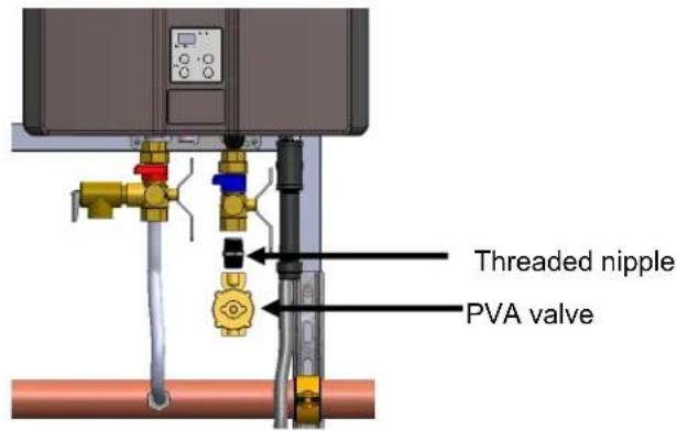
- For TRW03ST racks, a PVA valve and threaded nipple (supplied in Kit 104000278) must be added to the cold flex line assembly on the second RUC98. See the next step for detailed instructions.

PVA Valve

Threaded Nipple
- Remove the cold flex line from the second RUC98 unit.
text_image
RUR98 RUC98 RUC98 Cold Flex Line- Install the PVA valve and threaded nipple (supplied in Kit 104000278) to the cold water isolation valve:
• Install the threaded nipple to the cold water isolation valve.
• Install the PVA valve onto the threaded nipple.
text_image
Threaded nipple PVA valve- Re-install the cold flex line.

natural_image
Industrial piping system with valves and tubing, no visible text or symbols- Conversion steps are complete. Configure water heater settings as stated in the note below.
IMPORTANT:
When conversion steps are complete, the water heater recirculation settings must be adjusted. Refer to the "Cross Over Mode" section in the "Rinnai Direct Vent Tankless Water Heater with Integrated Pump Installation and Operation Manual" (shipped with KBP water heater models) for detailed instructions (Installation Instructions ▶ Recirculation Modes ▶ Cross Over Mode).
MSB Installation
All of the water heaters should be electronically connected using the MSB control system. The only exception is when a water heater is dedicated to recovering a tank. The MSB kits can electronically connect up to 25 water heaters.
When over 5 water heaters are connected together, MSB-M units are connected using MSB-C2 kits.
If multiple MSB-M are used, then at least three water heaters should be connected to each MSB-M. Example: With 7 water heaters, one MSB-M should control 4 water heaters and the other MSB-M should control 3 water heaters.
The temperature setting for all of the connected water heaters is controlled by the temperature controller connected to the water heater with the master MSB Board. Temperature controllers connected to the other units will provide maintenance codes for their respective units.
On applicable models a single MCC-91 can be connected to the master MSB Board to provide temperatures greater than 140^ F for all the water heaters in the MSB system.

flowchart
graph TD
    A["Water Heater PC board"] -->|C1| B["A"]
    A -->|C2| C["M"]
    B --> D["Cell 1"]
    B --> E["Cell 2"]
    B --> F["Cell 3"]
    C --> G["Cell 4"]
    C --> H["Cell 5"]
    C --> I["Cell 6"]
    D --> J["Cell 7"]
    E --> K["Cell 8"]
    F --> L["Cell 9"]
    G --> M["Cell 10"]
    H --> N["Cell 11"]
    I --> O["Cell 12"]
    J --> P["Cell 13"]
    K --> Q["Cell 14"]
    L --> R["Cell 15"]
    M --> S["Cell 16"]
In the diagram above, 25 water heaters are electronically connected. Each bank of 5 is controlled by an MSB-M control board. These boards are connected to each other with MSB-C2 cables. One MSB-M is the controlling or master MSB-M for the entire system.
M MSB-M control board
(A) Connector cable A (part of MSB-M kit; replace with MSB-C3 cables for V Series)
C1 MSB-C1 cable (9.8 feet) for connecting water heaters within a banked system (up to 5), (use MSB-C3 cables for V Series)
C2 MSB-C2 cable (26.2 feet) for connecting MSB-M control boards (up to 5)
MSB Installation
- On the master MSB, one connector is connected to the terminal connector and the other one is connected to the MSB Communication cable.
- When 2 MSB boards are used a MSB Communication cable will be installed between the master MSB board and the second MSB. The open connector will have the Terminal connector installed on both MSB boards.
A maximum of 5 MSB boards can be connected to each other. The terminal connector is connected on the terminal MSB which has an open connector.
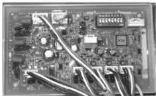
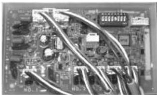
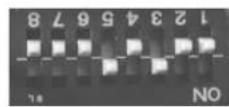
NOTE: When viewing the installed MSB board, the dip switch will be as shown below (upside down). - Set No 3 switch on the master MSB to ON. The LED light 6 should turn ON confirming the connection.
- Set No 4 switch on the second MSB to ON. The LED light 6 should turn ON confirming the connection.
- Set No 3 and No 4 switches on the third MSB board to ON. The LED light 6 should turn ON confirming the connection.
- Set the No 5 switch on the fourth MSB board to ON. The LED light 6 should turn ON confirming the connection.
- Set No 3 and No 5 switches on the on the fifth MSB board to ON. The LED light 6 should turn ON confirming the connection.
Master MSB board

natural_image
Close-up of an electronic circuit board with visible traces and components (no readable text or symbols)2nd MSB board
natural_image
Close-up of an electronic circuit board with various components and wires (no visible text or symbols)2nd to 4th MSB board
natural_image
Close-up of an electronic circuit board with visible traces and components (no readable text or symbols)5th or Terminal MSB board

natural_image
Close-up of an electronic circuit board with visible traces and components (no readable text or symbols)


Final Checklist
☐ The water heater is not subject to corrosive compounds in the air.
☐ The water supply does not contain chemicals or exceed total hardness that will damage the heat exchanger.
☐ Clearances from the water heater unit are met.
☐ Clearances from the vent termination / air intake are met.
For indoor models, ensure you have used the correct venting products for the model installed and that you have completely followed the venting manufacturer's installation instructions and these installation instructions.
☐ For indoor models, verify that the vent system does not exceed the maximum length for the number of elbows used.
☐ For indoor models, verify that SW 1 in DIPSW 1 has been adjusted for vent length if necessary. Refer to the section on Maximum Vent Length.
☐ Purge the water line of all debris and air by closing the hot isolation valve and opening the cold isolation valve and its drain. Debris will damage the water heater. Use a bucket or hose if necessary.
☐ Ensure that hot and cold water lines are not crossed to the unit and are leak free.
☐ A manual gas control valve has been placed in the gas line to the water heater.
☐ Ensure that a pressure relief valve is installed with a rating that exceeds the BTU input of the water heater model. Refer to the rating plate on the side of the water heater for BTU input.
☐ Clean the inlet water filter by closing the cold and hot water inlet isolation (shut-off) valves. Put a bucket under the filter at the bottom of the water heater to catch any water that is contained inside the unit. Unscrew the water filter. Rinse the filter to remove any debris. Install the filter and open the isolation valves.
☐ Check the gas lines and connections for leaks.
☐ Confirm that the gas inlet pressure is within limits.
☐ Confirm that the water heater is rated for the gas type supplied.
☐ Confirm that the electricity is supplied from a 120 VAC, 60 Hz power source, is in a properly grounded circuit, and turned on.
□ Verify the temperature controller is functioning properly.
☐ Verify that SW 2 and SW 3 in DIPSW 1 is set correctly for your altitude.
☐ Verify the system is functioning correctly by connecting your manometer to the gas pressure test port on the water heater. Operate all gas appliances in the home or facility at high fire. The inlet gas pressure at the water heater must not drop below that listed on the rating plate.
☐ DO NOT introduce toxic chemicals such as those used for boiler water treatment to the potable water used for space heating.
☐ If the water heater is not needed for immediate use, then drain the water from the heat exchanger.
□ Install the front panel.
☐ Explain to the customer the importance of not blocking the vent termination or air intake.
☐ Explain to the customer the operation of the water heater, safety guidelines, maintenance, and warranty.
☐ The installation must conform with local codes or, in the absence of local codes, with the National Fuel Gas Code, ANSI Z223.1/NFPA 54, or the Natural Gas and Propane Installation Code, CSA B149.1. If installed in a manufactured home, the installation must conform with the Manufactured Home Construction and Safety Standard, Title 24 CFR, Part 3280 and/or CAN/SCA Z240 MH Series, Mobile Homes.
☐ Inform the consumer if the isolation valves are not installed or if a water softening system is not installed.
☐ Leave the entire manual taped to the water heater (indoor models), temperature controller (outdoor models), or give the entire manual directly to the consumer.
TRW REPLACEMENT PARTS
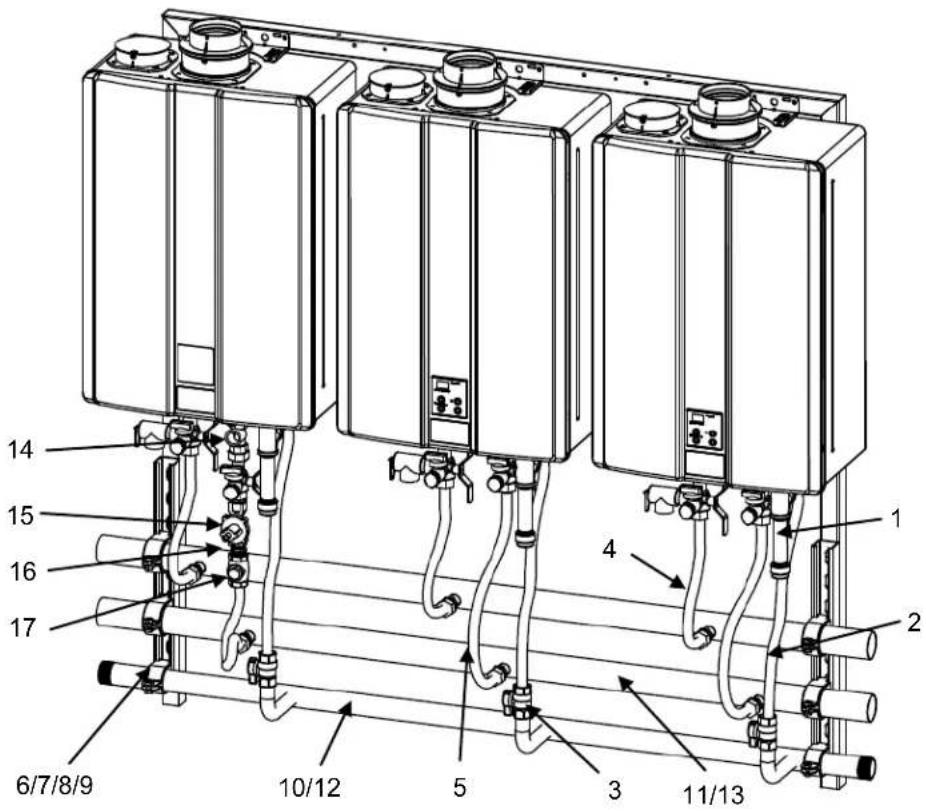
text_image
14 15 16 17 6/7/8/9 10/12 5 3 11/13 4 1 2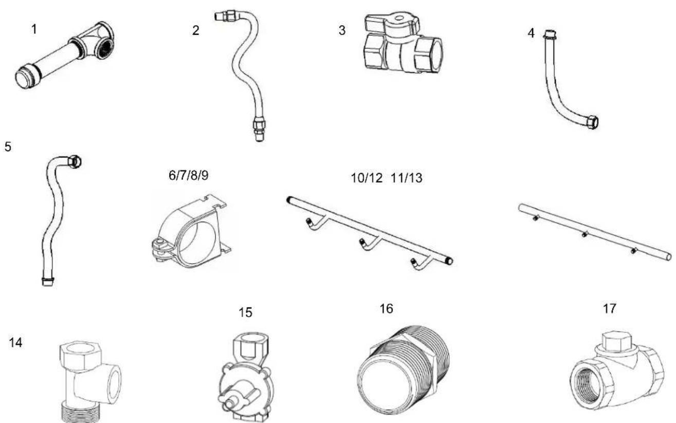
| ALL TRW | |
| REF. # | Description |
| 1 | Dirt Leg |
| 2 | Gas Flex Line Assembly |
| 3 | Gas Valve |
| 4 | Hot Water Flex Line |
| 5 | Cold Water Flex Line |
| 6 | Cush Clamp 2.63ID |
| 7 | Cush Clamp 2.125ID |
| 8 | Cush Clamp 1.90ID |
| 9 | Cush Clamp 1.66ID |
| TRW03 / TRW03ST | |
| 10 | Manifold, Gas - 3WM |
| 11 | Manifold, Water - 3WM |
| TRW02 / TRW02SE / TRW02ST | |
| 12 | Manifold, Gas - 2WM |
| 13 | Manifold, Water - 2WM |
| TRW02ST / TRW03ST | |
| 14 | Relocation Adapter |
| 15 | PVA Valve |
| 16 | Threaded Nipple |
| 17 | Check Valve |
TRC REPLACEMENT PARTS

text_image
Technical diagram of a multi-chamber industrial or electrical enclosure with numbered components and piping connections| TRC02 | |
| REF. # | Description |
| 1 | Dirt Leg |
| 2 | Gas Flex Line Assembly |
| 3 | Gas Valve |
| 4 | 18" Flex Line |
| 5 | 21" Flex Line |
| 6 | Hot Water Manifold |
| 7 | Cold Water Manifold |
| 8 | Gas Manifold |
| 9 | Cush Clamp 1.66ID |
| 10 | Cush Clamp 1.625ID |

text_image
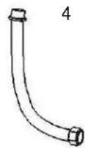
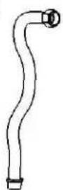
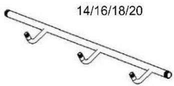
1 2 3 4/5 9/10 6 7 8TRS REPLACEMENT PARTS
text_image
6 22/23 1 4 5 2 12 14/16/18/20 15/17/19/21 3 13 7/8/9/10/11
natural_image
Line drawing of a cylindrical mechanical component with flanges and a handle (no text or symbols)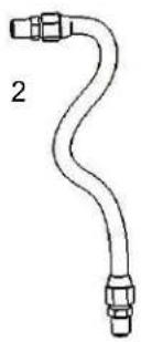
natural_image
Simple line drawing of a curved pipe or conduit with two connectors (no text or symbols)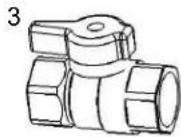
5
7/8/9/10/11

13

ALL TRS/TRSILW
REF. # Description
1 Dirt Leg
2 Gas Flex Line Assembly
3 Gas Valve
4 Hot Water Flex Line
5 Cold Water Flex Line
6 Wall Bracket
7 Cush Clamp 2.63ID
8 Cush Clamp 2.125ID
9 Cush Clamp 1.90ID
10 Cush Clamp 1.66ID
11 Cush Clamp 1.05ID
12 Frame, Rack Left Rear
13 Frame, Rack Right Rear
14 Manifold, Gas - 6B2B
15 Manifold, Water - 6B2B
TRS02/TRS03/TRS04
16 Manifold, Gas - 4B2B
17 Manifold, Water - 4B2B
TRS03IL/TRS03ILW/TRS23
18 Manifold, Gas - 3WM
19 Manifold, Water - 3WM
TRS02IL/TRS02ILW
20 Manifold, Gas - 2WM
21 Manifold, Water - 2WM
TRS03/TRS03ILW/TRS03IL/TRS04/TRS36/TRS46
22 Electrical - 4 Connections
TRS05/TRS06
23 Electrical - 6 Connections
natural_image
Simple line drawing of a mechanical bracket or rod with four end points (no text or symbols)
natural_image
Simple line drawing of a cylindrical object with four small circular holes, labeled '15/17/19/21' above (no other text or symbols)
natural_image
Pure electrical circuit lines without any symbols52 Rinnai Rack Installation
TRS REPLACEMENT PARTS

text_image
Technical diagram of industrial piping system with labeled components and a red triangular warning triangle indicating safety risk.| CONDENSATE MANIFOLD | |
| RACK DESCRIPTION | |
| TRS03IL/ILW | 3 Connections - In-Line |
| TRS03 3 Connections - 3B2B | |
| TRS04 4 Connections - 4B2B | |
| TRS05 5 Connections - 5B2B | |
| TRS06 6 Connections - 6B2B | |
| TRS36 3 Connections - 3B2B | |
| TRS46 4 Connections - 4B2B | |
Extended Limited LABOR Warranty\*
Tankless Rack System
REGISTRATION REQUIRED\*
Rinnai is providing the opportunity to extend your Rinnai Standard Limited Warranty for labor only on the tankless water heater product installed as part of the Tankless Rack System and used in a commercial application. You must register the product within 30 days of purchase of the system to qualify.
The limited warranty period on the Labor coverage for Tankless Water Heaters installed on the Tankless Rack System is extended for an additional 12 months (a total of 24 months labor coverage from date of purchase), when registered. Products not registered will still be covered under the Rinnai standard product limited warranty as provided in the Operating Instruction manual which comes with the Tankless water heater. Warranty information is also available on Rinnai's web site at www.rinnai.us. You can register at www.rinnairegistration.com or by calling 1-866-RINNAI-1 (746-6241), except registration is not required in California and Quebec.
What is covered?
This Limited Warranty covers any defects in materials or workmanship when the product is installed and operated according to Rinnai written installation instructions, subject to the terms within this Limited Warranty document. This Limited Warranty applies only to products that are installed correctly. Improper installation may void this Limited Warranty. In order for this warranty to apply, it is required that you use a licensed professional who has attended a Rinnai installation training class before installing this water heater. This Limited Warranty extends to the original purchaser and subsequent owners, but only while the product remains at the site of the original installation. This Limited Warranty only extends through the first installation of the product and terminates if the product is moved or reinstalled at a new location.
How long does coverage last?
| Item Period of | Coverage (from date of purchase) |
| Tankless Water Heaters | Refer to the Water Heater Installation and Operation Manual shipped with your system for complete warranty details on your Rinnai Tankless Water Heater. |
| Rack and Components | 1 year |
Only applicable if product is registered within 30 days of purchase and the other conditions are met. Note to California and Quebec Residents, and residents of other jurisdictions that prohibit warranty benefits conditioned on registration, registration is not required to obtain longer warranty periods and failure to register does not diminish your warranty rights. www.rinnai.us/warranty
What will Rinnai do?
Rinnai will repair or replace the covered product or any part or component that is defective in materials or workmanship as set forth. Rinnai will pay reasonable labor charges associated with the repair or replacement of any part or component of the tankless water heater. All repair parts must be genuine Rinnai parts. All repairs or replacements must be performed by a licensed professional that is properly trained, state qualified or licensed to do the type of repair.
Replacement of the product may be authorized by Rinnai only. Rinnai does not authorize any person or company to assume for it any obligation or liability in connection with the replacement of the product. If Rinnai determines that repair of a product is not possible, Rinnai will replace the product with a comparable product at Rinnai's discretion. The warranty claim for product parts and labor may be denied if a component or product returned to Rinnai is found to be free of defects in material or workmanship; damaged by improper installation, use or operation; or damaged during return shipping.
How do I get service?
You must contact a licensed professional for the repair of a product under this Limited Warranty. For the name of a licensed professional please contact your place of purchase, visit the Rinnai website (www.rinnai.us), call Rinnai at 1-800-621-9419 or write to Rinnai at 103 International Drive, Peachtree City, Georgia 30269.
Proof of purchase is required to obtain warranty service. You may show proof of purchase with a dated sales receipt, or by registering within 30 days of purchasing the product. To register your tankless water heater, please visit www.rinnai.us. For those without internet access, please call 1-866-RINNAI1 (746-6241). Receipt of Registration by Rinnai will constitute proof-of-purchase for this product. However, Registration is not necessary in order to validate this Limited Warranty.
What is not covered?
This Limited Warranty does not cover any failures or operating difficulties due to the following:
- accident, abuse, or misuse
• alteration of the product or any component part
• misapplication of this product
• improper installation (such as but not limited to)
◇ Product being installed in a corrosive environment
◇ condensate damage
◇ improper venting
◇ incorrect gas type
◇ incorrect gas or water pressure
◇ absence of a drain pan under the appliance
- water quality
• improper maintenance (such as but not limited to scale build-up, freeze damage, or vent blockage)
- incorrect sizing
• any other cause not due to defects in materials or workmanship
• Problems or damage due to fires, flooding, electrical surges, freezing or any acts of God.
- force majeure
There is no warranty coverage on product installed in a closed loop application, commonly associated with space heating only applications.
The integrated controller on indoor models has a 1 year warranty on parts.
This Limited Warranty does not apply to any product whose serial number or manufacture date has been defaced. This Limited Warranty does not cover any product used in an application that uses chemically treated water such as a pool or spa heater. This appliance is suitable for filling large or whirlpool bath tubs with potable water.
Limitation on warranties
No one is authorized to make any other warranties on behalf of Rinnai America Corporation. Except as expressly provided herein, there are no other warranties, expressed or implied, including, but not limited to warranties of merchantability or fitness for a particular purpose, which extend beyond the description of the warranty herein and further Rinnai shall not be liable for indirect, incidental, special, consequential or other similar damages that may arise, including lost profits, damage to person or property, loss of use, inconvenience, or liability arising from improper installation, service or use. Some states do not allow the exclusion or limitation of incidental or consequential damages, so the above limitation may not apply to you.
Any implied warranties of merchantability and fitness arising under state law are limited in duration to the period of coverage provided by this Limited Warranty, unless the period provided by state law is less. Some states do not allow limitations on how long an implied Limited Warranty lasts, so the above limitation may not apply to you.
This Limited Warranty gives you specific legal rights, and you may also have other rights which vary from state to state.
www.rinnai.us/warranty
A tradition of
TRUE RELIABILITY.
For nearly 100 years, we at Rinnai have been fiercely committed to delivering nothing less than a superior experience at every touch point.
Beyond manufacturing the highest quality products, our people stand behind all that we make—before, during and long after installation. From the 24/7/365 technical support for professionals, to our national network of independent installers, to on-staff engineers who can assist with choosing the right products and sizes—we're inspiring confidence right along with the comfort our solutions provide.

natural_image
Product photo of industrial air purification units including refrigerators and refrigerators with cooling fans (no visible text or labels)Rinnai®
Learn more about Rinnai high-performance Tankless Water Heaters, Hybrid Water Heating Systems, Boilers, Vent-Free Fan Convectors and EnergySaver® Direct Vent Wall Furnaces at:
rinnai.us
Rinnai America Corporation • 103 International Drive, Peachtree City, GA 30269 1-800-621-9419 • rinnai.us
©2017 Rinnai America Corporation. Rinnai America Corporation continually updates materials, and as such, content is subject to change without notice. Local, state provincial, federal and national fuel gas codes must be adhered to prior to and upon installation.
100000294(11)
2/2017