Enterprise 4300R - TV amplifier Wilson - Free user manual and instructions
Find the device manual for free Enterprise 4300R Wilson in PDF.


User questions about Enterprise 4300R Wilson
0 question about this device. Answer the ones you know or ask your own.
Ask a new question about this device
Download the instructions for your TV amplifier in PDF format for free! Find your manual Enterprise 4300R - Wilson and take your electronic device back in hand. On this page are published all the documents necessary for the use of your device. Enterprise 4300R by Wilson.
USER MANUAL Enterprise 4300R Wilson
In-Building Cell Signal Amplifier with Multi-Tower Targeting (MTT) Technology
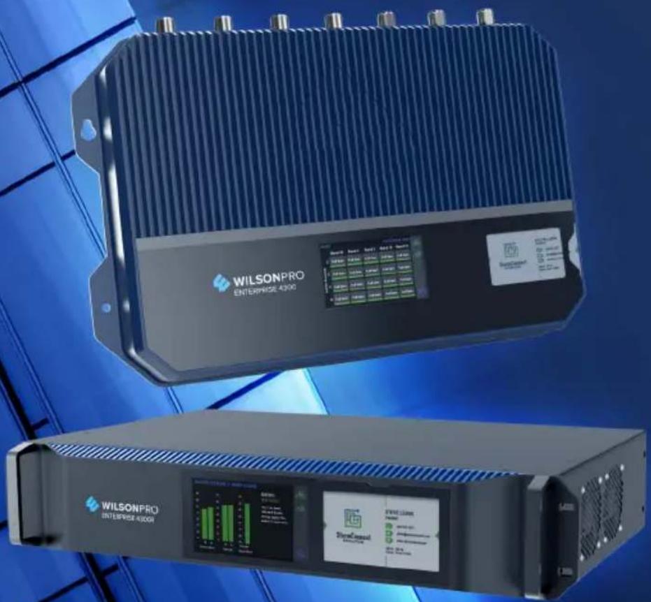
natural_image
Two industrial electronic devices labeled 'WILSONPRO ENTERPRISE 4300' with visible control panel and display, against a blue background (no readable text beyond branding)Installation Guide
Index
Package Contents 1
About The Enterprise 4300 & 4300R 2
Additional Features 4
Installation Diagram 5
Menu System 8
WilsonPro Cloud 17
Local Ethernet Configuration Utility 34
Safety Guidelines 42
Specifications 44
Warranty 45
Package Contents
Enterprise 4300 SKU 460152
Enterprise 4300
Amplifier
Wide Band Directional Antenna (314411)
Dome Antennas
(qty. 4)
(304412)
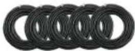
100 ft. Wilson400 Cable (qty. 5) (952300)

2 ft. Wilson400
Cable
(952402)

50 Ohm Lightning
Surge Protector
(859902)
Enterprise 4300R SKU 460153
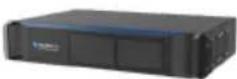
Enterprise 4300R
Amplifier
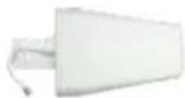
Wide Band Directional
Antenna
(314411)
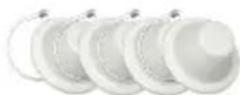
Dome Antennas
(qty. 4)
(304412)
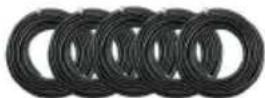
100 ft. Wilson400 Cable
(qty. 5)
(952300)

2 ft. Wilson400 Cable (952402)

50 Ohm Lightning
Surge Protector
(859902)

WILSONPRO
ENTERPRISE 43018
Enterprise 4300 & 4300R
In-Building Cell Signal Amplifier Systems
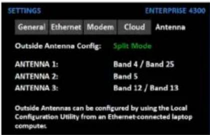
Frequency-specific “split mode” option, facilitating separate outdoor antennas for different bands, resulting in improved indoor coverage.

natural_image
Metal cloud-shaped icon with a lightning bolt and three horizontal lines, rendered in metallic tones against a dark background (no text or symbols)Remote system monitoring. Connects to WilsonPro Cloud service via internal, pre-activated LTE modem or Ethernet.

natural_image
Silhouette of a tall tower against a sunset sky with faint concentric rings (no text or symbols visible)High max uplink power (up to +26 dBm): will reach distant cell towers.

natural_image
Exterior view of a modern building with green digital overlay (no visible text or symbols)High max downlink power (+17 dBm per port) for up to 100,000 sq ft coverage with a strong "5 bar" outside signal.
natural_image
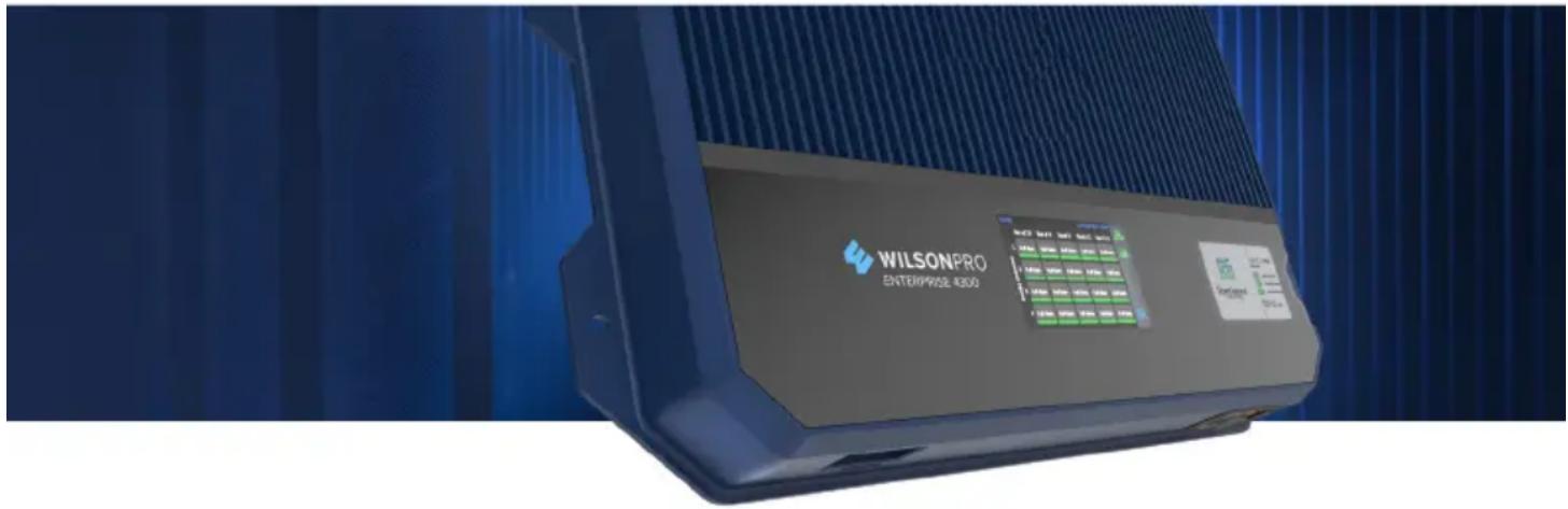
Exterior view of a Wilson Pro Enterprise 4300 industrial control unit (no signage or text overlays)The Enterprise 4300 & 4300R cell signal amplifier systems provide significantly enhanced 4G LTE and 3G voice and data coverage inside buildings where cell signals may not otherwise penetrate. Installation of an Enterprise 4300 & 4300R cell signal amplifier system results in fewer dropped calls, improved voice quality, uninterrupted texts, and faster data speeds—along with better audio and video streaming.
For installers and integrators, subscribing to the WilsonPro Cloud means you can sell your clients extended service plans, generating recurring revenue streams for your business. And for your clients, the WilsonPro Cloud provides ultra-high system reliability and guaranteed uptime.
The Enterprise 4300 & 4300R amplifiers connect to the WilsonPro Cloud right out of the box via an LTE modem on the donor antenna, or through a traditional hardwired Ethernet port. The wireless LTE connection is included in the annual WilsonPro Cloud subscription, so no additional Internet connection is required.
The Enterprise 4300 & 4300R cell signal amplifier systems also incorporate Wilson Electronics' state-of-the-art XDR (eXtended Dynamic Range) technology that prevents signal overload conditions which can, in accordance with regulations, force the amplifier to shut down. When the Enterprise 4300 & 4300R cell signal amplifier systems sense that any incoming cell signal is too strong and threatens to overload the system, XDR automatically reduces amplifier gain to compensate while maintaining signal coverage throughout the building. The Enterprise 4300 & 4300R cell signal amplifier systems incorporate an easy-to-use color LCD touch screen, and all antenna ports are located on the same side of the unit for simple installation. Like all WilsonPro cell signal amplifiers, the Enterprise 4300 & 4300R cell signal amplifier systems are universal: they work for all cellular devices, all services and all U.S. and Canada cell phone carriers.
Additional Features

Extended Dynamic Range (XDR) for continuous connectivity:
XDR lets the Enterprise 4300 & 4300R systems work with an incoming signal and never shut down due to a strong outside signal.

Choice of Wall-Mount or Rack-Mount Installation: All indoor and outdoor port(s) are located on top of the amplifier for easy antenna connections, while an exposed mounting flange on each amplifier provides for simple installation.

Onboard Software for Intelligent Control: The amplifier is automatically controlled by onboard software, ensuring connectivity throughout large spaces and multi-story buildings. The amplifier will adjust its gain level up or down as required by the conditions of the immediate signal environment.

Color LCD Touch Screen: The Enterprise 4300 & 4300R systems utilize a color LCD touch screen, for assessing amplifier performance and viewing amplifier configuration.
Independently Controlled Ports: Four independently controlled indoor antenna ports facilitating up to 100,000 sq. ft. of indoor coverage.
Installation Diagram
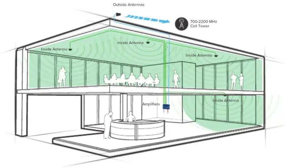
The Enterprise 4300 & 4300R supports up to four inside antennas and are capable of operating in traditional Common Mode, in which all amplifier cell bands use the same outdoor antenna, or Split Mode, in which cell bands use separate outdoor antennas.
Split Mode
Split mode is advantageous for an installation in which cell towers for different bands are located in different directions. Outdoor directional antennas can be pointed to provide maximum cell coverage for each band.
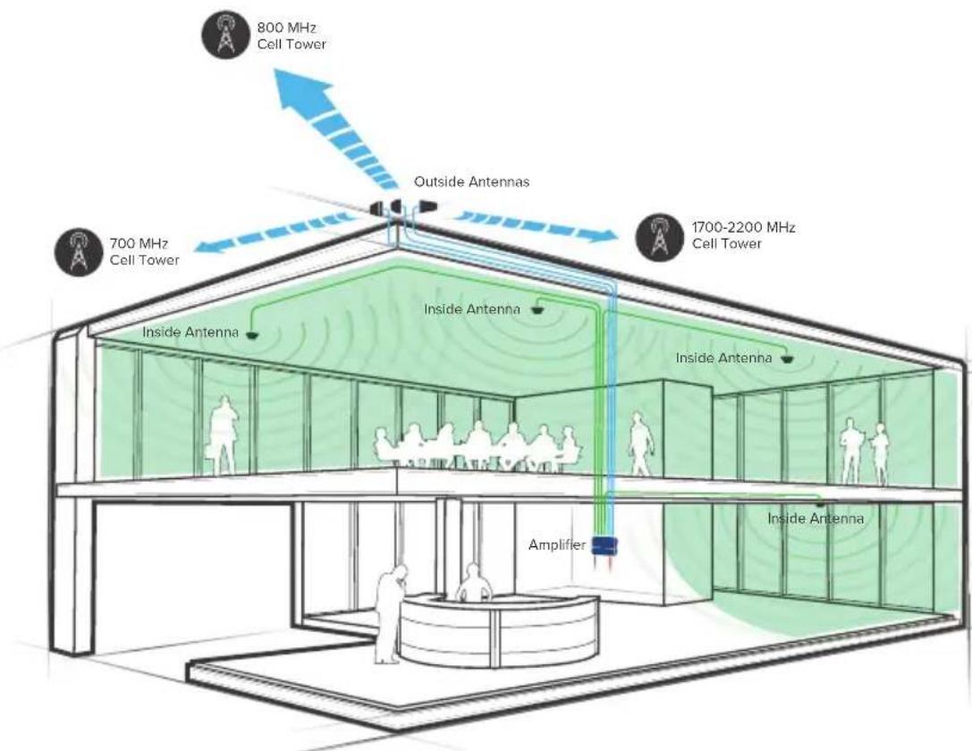
Note: A Wilson Lightning Surge Protector is recommended for all building installations. Make sure the protector is installed outside the building at point of entry connected to a suitable ground and in line between the Outside Antennas and the Signal Amplifier.
INSTALLATION DIAGRAM cont.)
Common Mode
Common mode can be used for an installation in which cell towers for different bands are located in the same direction.
Note: The Enterprise 4300 & 4300R is configured to common mode by default.
Post-Install Setup
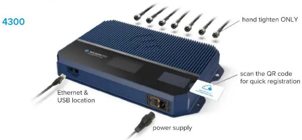
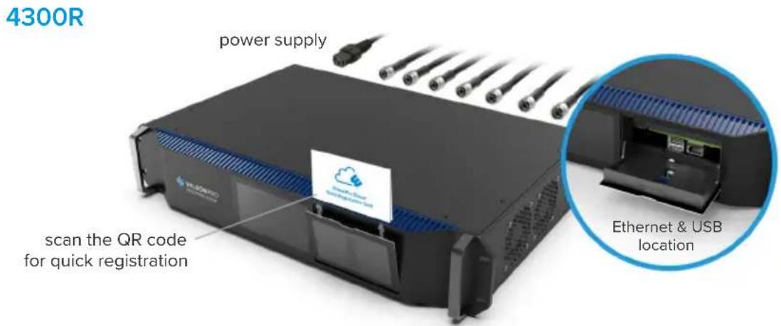
The Enterprise 4300 & 4300R systems are designed with advanced internal programming, which allows it to automatically adjust for a variety of conditions, including the added functionality, alerts, and troubleshooting of an enhanced cloud management and monitoring solution.
Once the AC power cable and antenna cables are connected, scan the QR code on the Quick Registration Card to add the amplifier to your WilsonPro Cloud account. For detailed instructions see the WilsonPro Cloud section.
Menu System
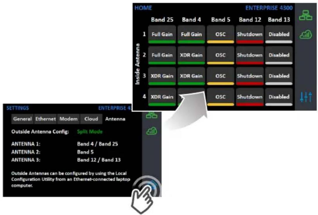
The Enterprise 4300 & 4300R takes about 8 seconds to boot up. Once boot up is complete, the home screen will appear, showing the amplification and status of each port and band.
Start Up Screen

Home Screen
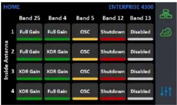
Band Menu Color Description

Green indicates that a band is operating correctly with maximum allowable gain.
Yellow indicates band gain reduction because of an oscillation condition. Reposition antennas (increase separation between indoor and outdoor antennas, and point in opposite directions) and then reboot (turn the unit off & on) the Enterprise 4300 & 4300R system to reactivate the band and maximize performance. When adequate separation is achieved, the yellow lights will return to green upon reboot.
Note: when the light is yellow, the band is operational; however, performance is reduced.
(MENU SYSTEM cont.)

Red indicates a band has been shut down because of a severe oscillation condition or repeated oscillation. Reposition antennas (increase separation between indoor and outdoor antennas, and point in opposite directions) and then reboot (turn the unit off & on) the Enterprise 4300 & 4300R system to reactivate the band and maximize performance. When adequate separation is achieved, the red light(s) will return to green upon reboot.
Gray indicates band has been disabled.
Settings Screen
Tap 'Settings Icon' in the lower right corner to view the Settings Screen.
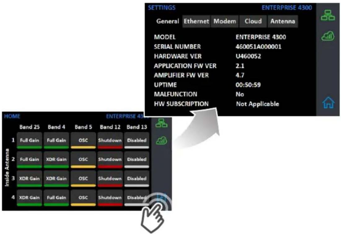
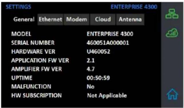
There are 5 Settings Screens represented by "tabs". Tap the tab heading to view each Settings Screen. General settings below.
Note: Bands and Ports are disabled or enabled from the Cloud or Local Amplifier Configuration Utility only.
(MENU SYSTEM - SETTINGS SCREEN cont.)
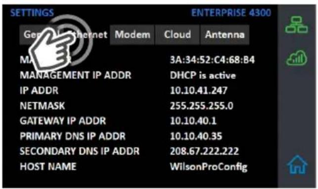
Ethernet Settings Tab
Modem Settings Tab
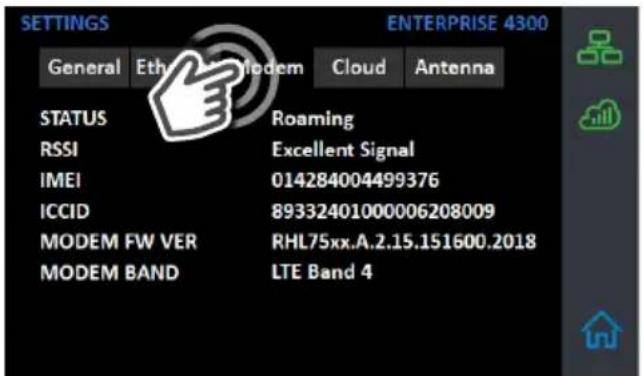
(MENU SYSTEM - SETTINGS SCREEN cont.)
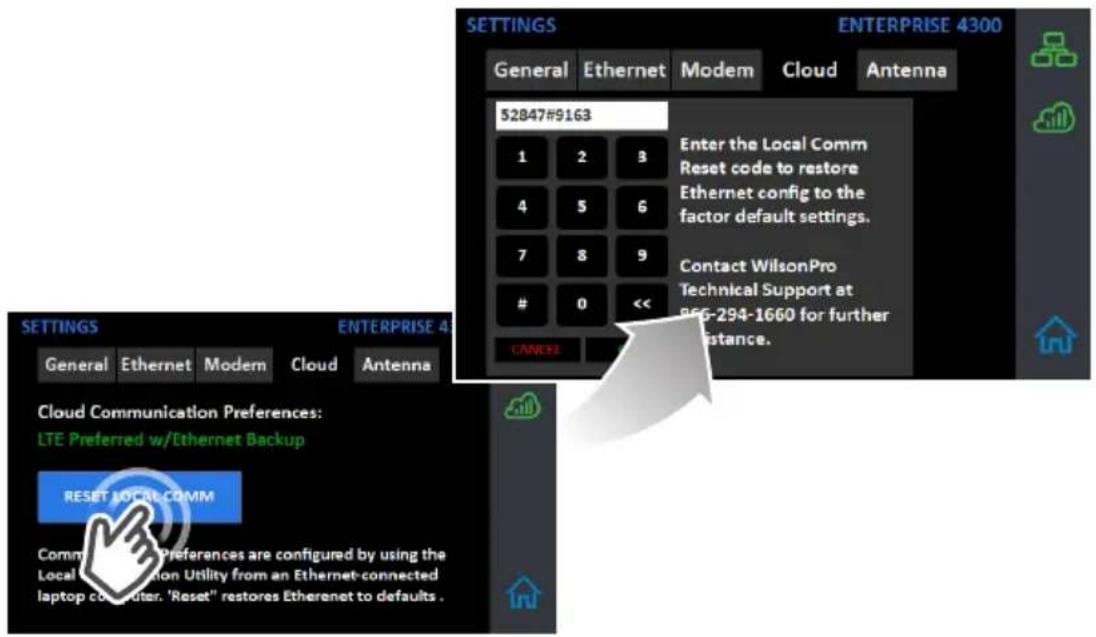
Cloud Communication Settings Tab
Note: The Reset Local Comm button is used in case the user has configured the amplifier such that the Local Amplifier Configuration Utility is not accessible, e.g., if the communication preferences are set to "LTE Only". The "reset" function will change the communication preferences to "LTE Preferred w/Ethernet Backup". It will also reset the login credentials for the Local Configuration Utility to factory defaults.
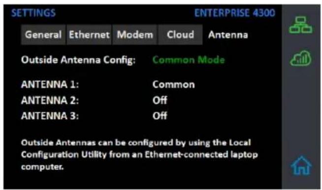
Antenna Settings Tab
Common Mode is configured from the Local Amplifier Configuration Utility and should be set when using a single Outside Antenna.
(MENU SYSTEM - SETTINGS SCREEN cont.)
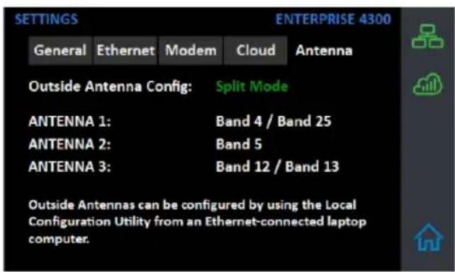
Split-Mode Configuration
Split Mode is configured from the Local Amplifier Configuration Utility and should be set when using separate Outside Antennas for Band 4/25, Band 5, and Band 12/13.
To go back to the Home Screen, tap on the Home Icon (in the lower right corner).
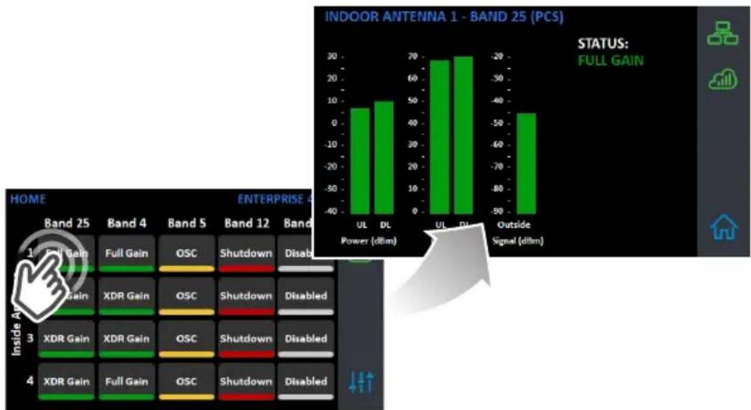
Band-Status Screens
To view specific band information (such as the strength of the received uplink & down-link signal, outside signal strength, and amplifier gain status) tap the desired band on the home screen.
bar
INDOOR ANTENNA 1 - BAND 25 (PCS) | Band | Power (dBm) | Status: Full Gain | | :--- | :--- | :--- | | UL | 70 | Full Gain | | DL | 60 | Full Gain | | UL | 70 | DL | | DL | 70 | DL | | Outside Signal (dBm) | -40 | Disabled | | Power (dBm) | 0 | Disabled | | XDR Gain | 0 | Disabled | | XDR Gain | 0 | Disabled | | XDR Gain | 0 | Disabled | | XDR Gain | 0 | Disabled | | XDR Gain | 0 | Disabled | | XDR Gain | 0 | Disabled | | XDR Gain | 0 | Disabled | | XDR Gain | 0 | Disabled | | XDR Gain | 0 | Disabled | | XDR Gain | 0 | Disabled | | XDR Gains | 0 | Disabled | | XDR Gains | 0 | Disabled | | XDR Gains | 0 | Disabled | | XDR Gains | 0 | Disabled | | XDR Gains | 0 | Disabled | | XDR Gains | 0 | Disabled | | XDR Gains | 0 | Disabled | | XDR Gains | 0 | Disabled | | XDR Gains | 0 | Disabled | | XDR Gains (Outside Signal dBm) | -50 | Disabled | The image displays a multi-panel layout with the main title 'HOME ENTERPRISE 4' and a legend indicating 'Full Gain' and 'Outside Signal (dBm)' in the top-right corner.Oscillation Example
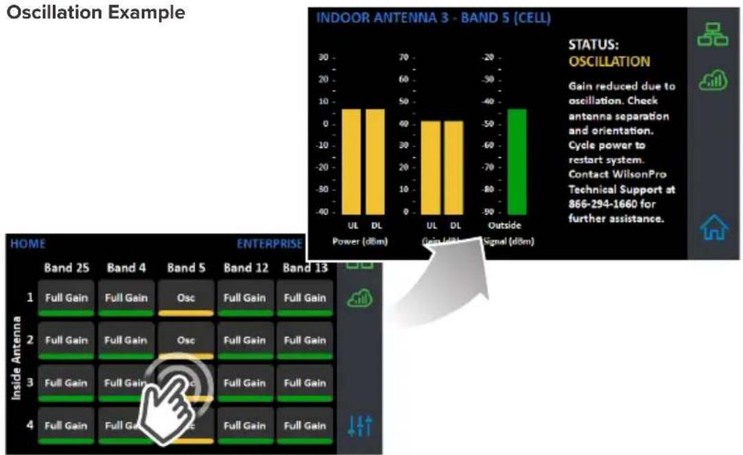
bar
INDOOR ANTENNA 3 - BAND 5 (CELL) | Category | Power (dBm) | Gain (dBm) | Signal (dBm) | | :--- | :--- | :--- | :--- | | UL | 70 | 40 | -40 | | DL | 70 | 40 | -40 | | Outside | -40 | -40 | -40 | | Inside Antenna | Band 25 | Band 4 | Band 5 | Band 12 | Band 13 | |---|---|---|---|---|---| | 1 | Full Gain | Full Gain | Osc | Full Gain | Full Gain | | 2 | Full Gain | Full Gain | Osc | Full Gain | Full Gain | | 3 | Full Gain | Full Gain | Osc | Full Gain | Full Gain | | 4 | Full Gain | Full Gain | Osc | Full Gain | Full Gain | STATUS: OSCILLATION Gain reduced due to oscillation. Check antenna separation and orientation. Cycle power to restart system. Contact WilsonPro Technical Support at 866-294-1660 for further assistance.(MENU SYSTEM - SETTINGS SCREEN cont.)
Shutdown Example
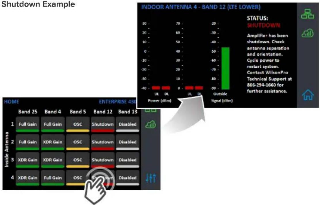
Connectivity Status Screens
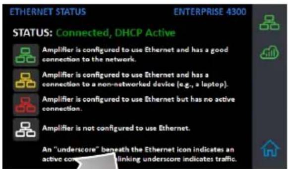
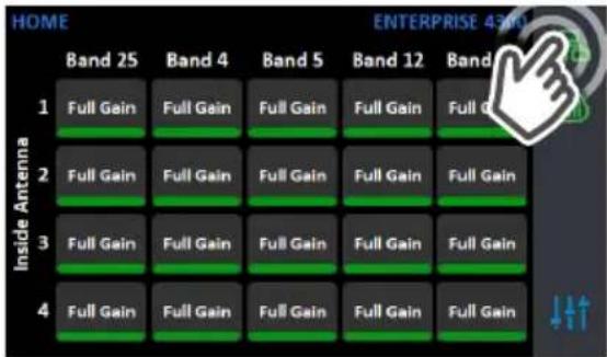
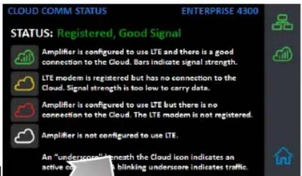
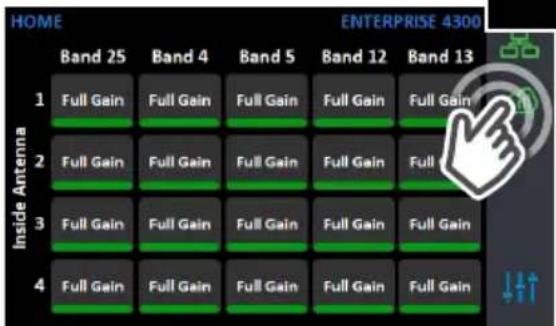
The three icons in the upper right provide status related to the Ethernet connection, Cloud connection, and USB device (if inserted).
Ethernet-Status Icon
Cloud-Status Icon
WilsonPro Cloud
The cloud-based platform for remote monitoring & control of cellular signal amplifiers
Enterprise 4300 & 4300R connects to WilsonPro Cloud via the internet, through a traditional RJ-45 “hardwired” Ethernet connection or via LTE connection through the outside antenna. The default setting is “Ethernet Preferred” (gives priority to Ethernet, but will switch to LTE if Ethernet is not connected). NOTE: The LTE modem and SIM card are installed and activated at the WilsonPro factory.
Logging into the WilsonPro Cloud via Ethernet
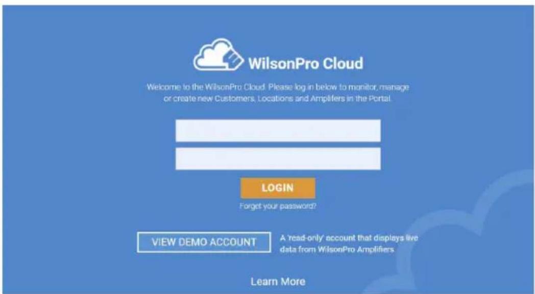
If you don't already have a WilsonPro Cloud™ account at cloud.wilsonpro.com, call 1-888-923-4448, Monday-Friday 8am-5pm MT so that your account can be created. Once your account is set up, you can then add multiple customers, locations, and amplifiers.
Your supported amplifiers can be added and managed via our WilsonPro Cloud website located at https://cloud.wilsonpro.com. Simply log in using your email address and password.
(WILSONPRO CLOUD cont.)
Customer Dashboard
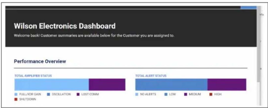
You can quickly check the status of all of your amplifiers from the Dashboard summary screen. The Total Alert Status represents the number of alert indications, for all amplifiers assigned to your account, that have not been acknowledged. After an alert is acknowledged, it is no longer included in this chart. Total Amplifier Status represents the current, near real-time status of all amplifiers associated with your account.
bar
| Category | Total AMPLIFIER STATUS | TOTAL ALERT STATUS | | ------------------ | ---------------------- | ------------------- | | FULL/XDR GAIN | High | No ALERTS | | OSCILLATION | Medium | Low | | LOST COMM | Medium | Medium | | SHUTDOWN | Low | High |Adding a Customer
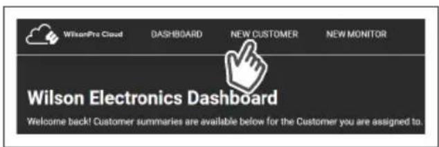
To create a new customer from the Dashboard screen, click on NEW CUSTOMER.
NOTE: If you don't already have a WilsonPro Cloud account at cloud.wilsonpro.com, call 1-888-923-4448, Monday-Friday 8am-5pm MT.
(WILSONPRO CLOUD - ADDING A CUSTOMER cont.)
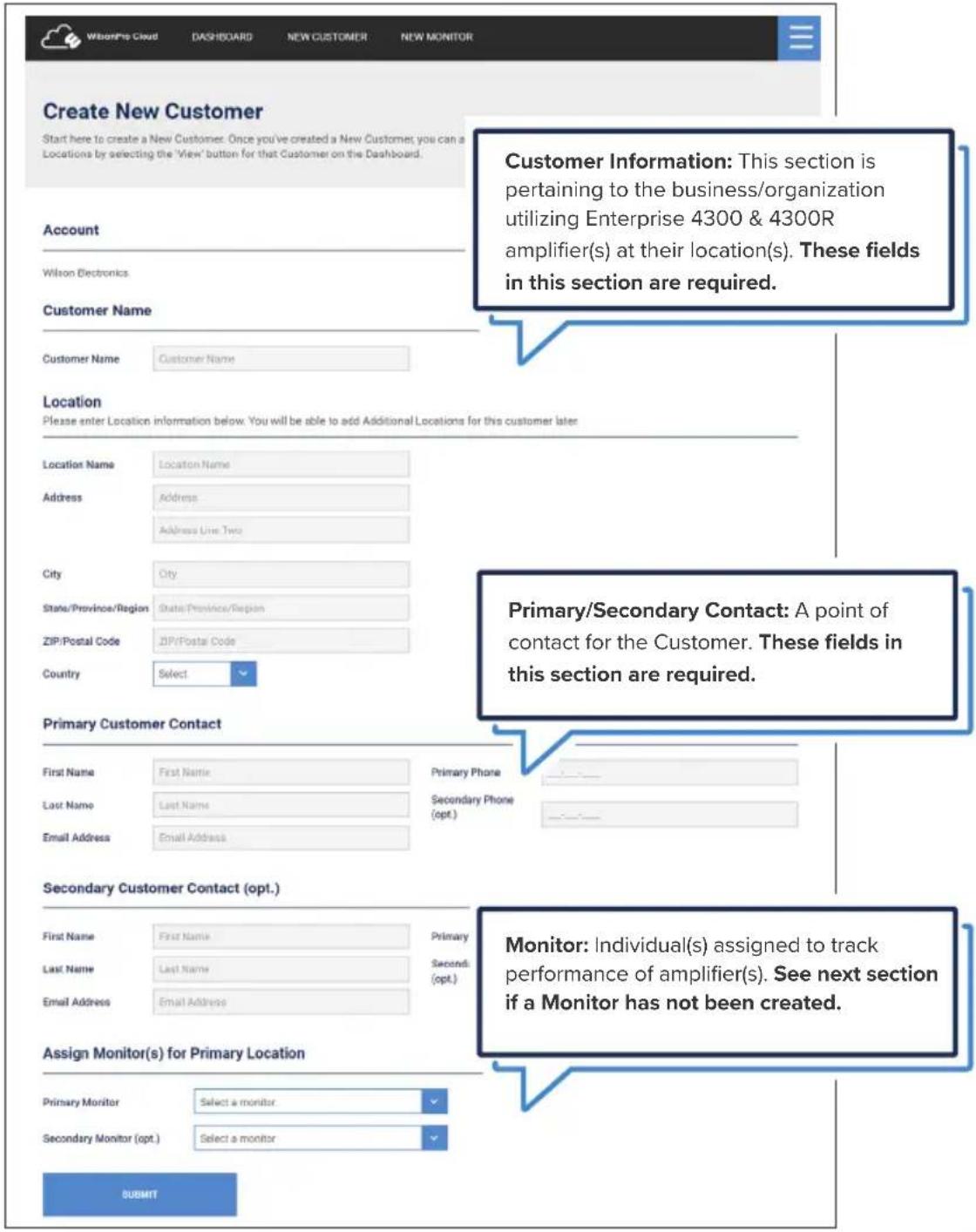
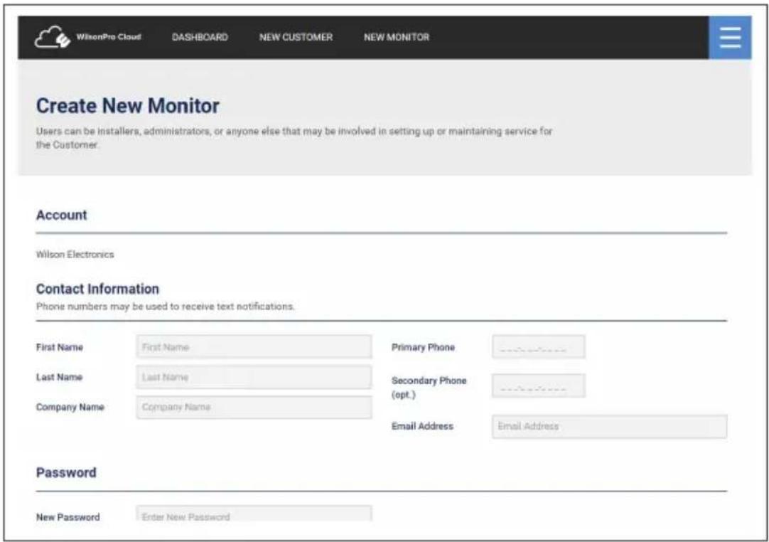
Enter information for Customer (business/organization utilizing the Enterprise 4300 & 4300R product), Primary Contact (notification recipient), and select a Monitor. After clicking on SUBMIT the new customer will appear on the dashboard page below the alert and status summary with a default location.
(WILSONPRO CLOUD - ADDING A CUSTOMER cont.)
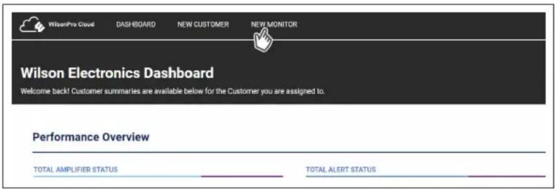
If a Monitor has not been created, click on NEW MONITOR at the top of the webpage. Installer/Integrator can assign Monitors to track the performance of the amplifier(s). A Monitor can be made Administrator, who can see all information within the account and create additional Monitors.
Enter information and click SUBMIT.
(WILSONPRO CLOUD cont.)
Creating an Additional Customer Location
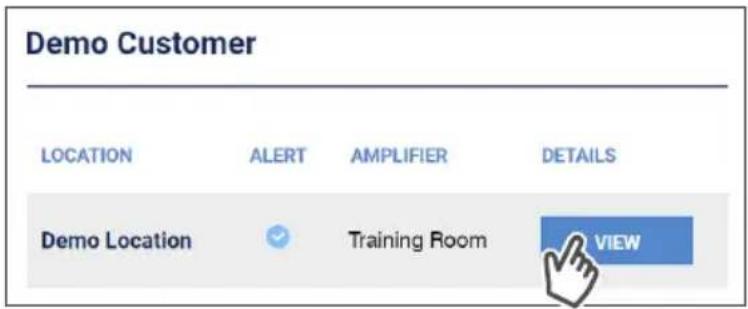
To create an additional customer location click VIEW.
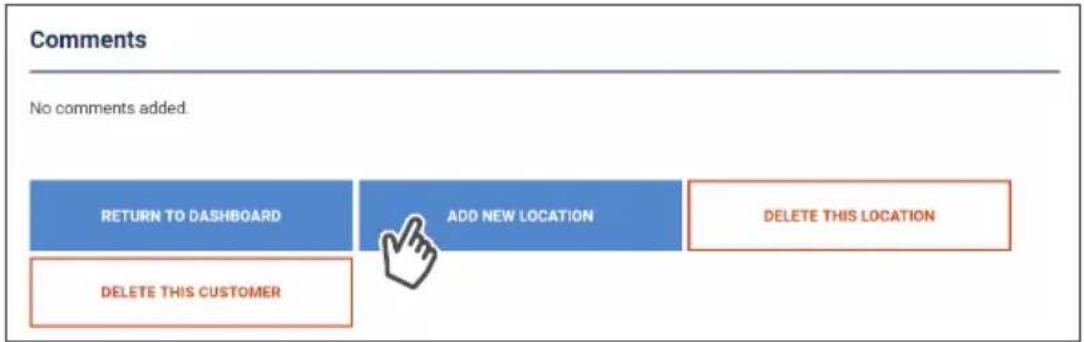
Then click ADD NEW LOCATION.
flowchart
graph LR
    A["RETURN TO DATABASE"] --> B["DELETE THIS CUSTOMER"]
    C["ADD NEW LOCATION"] --> D["DELETE THIS LOCATION"]
(WILSONPRO CLOUD - ADDING A CUSTOMER LOCATION cont.)
Enter information and click SUBMIT.
NOTE: Customer Information and Primary Contact fields are required, these must be populated before submitting page.

WilsonPro Cloud
DASHBOARD
NEW CUSTOMER
NEW MONITOR
Add Additional Location
Enter information for an Additional Location, below. The process is the same for Additional Locations as for the default Customer Location. You can also Configure Alert settings for this Location by pressing 'Configure Alerts' at the bottom of the screen.
Location
Please enter Location information below. You will be able to add Additional Locations for this customer later.
Location Name
Location Name
Address
Address
Address Line Two
City
City
State/Province/Region
State/Province/Region
ZIP/Postal Code
ZIP/Postal Code
(WILSONPRO CLOUD cont.)
Adding an Amplifier
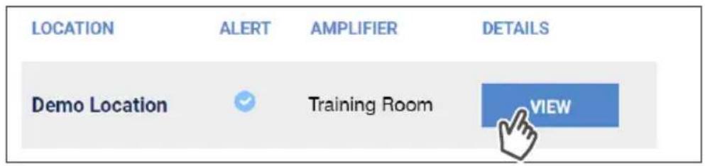
On the dashboard page, find the customer location you would like to add the amplifier and click VIEW.
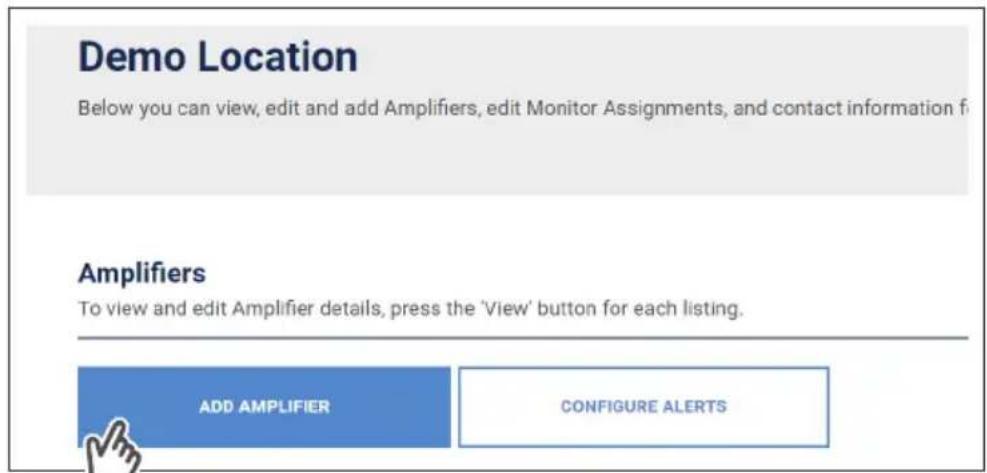
Then click ADD AMPLIFIER.
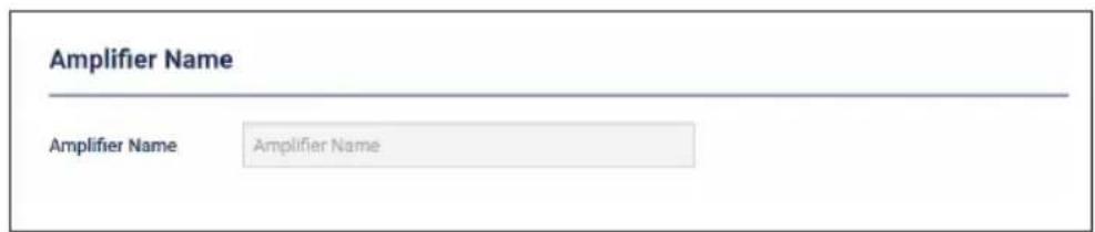
Add an amplifier name. An example: Hotel Lobby etc.
(WILSONPRO CLOUD - ADDING A AMPLIFIER cont.)
Click SCAN AMPLIFIER QR CODE located on Quick Setup Card (which is in the plastic sleeve on the amplifier).
Look Up Details (QR Code)
If available, you can use the camera on your mobile device to scan the Product bar code to look up the Amplifier detail

SCAN AMPLIFIER QR CODE
The serial number and MAC address will autopopulate after scanning QR code.
Click LOOK UP SERIAL NUMBERS. NOTE: The serial number and MAC address fields can be populated manually.
Serial Number
Serial Number
MAC Address
MAC Address (11:22:33:44:55:56)

LOOK UP SERIAL NUMBER
(WILSONPRO CLOUD cont.)
Amplifier Metrics
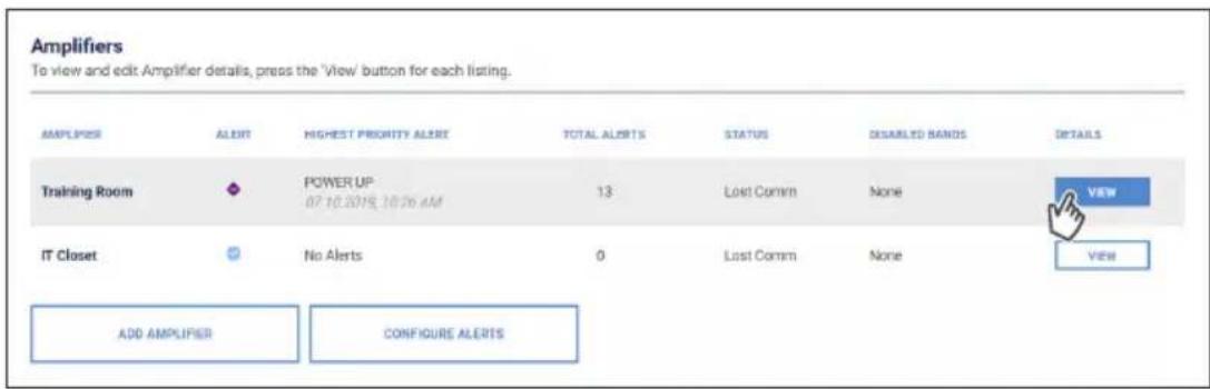
Now that the amplifier(s) have been added to the location, click VIEW to view details about the amplifier.
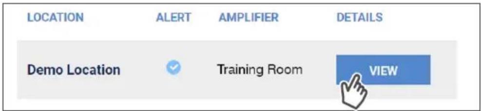
Click VIEW, in the amplifier list.
(WILSONPRO CLOUD - AMPLIFIER METRICS cont.)
Training Room Ports
To view and edit Port details, press the 'View' button for each listing.
| PORT | NAME | STATUS | DETAILS |
| Port 1 | Table | XDR Gain |  |
| Port 2 | Table2 | XDR Gain | |
| Port 3 | Table3 | XDR Gain | VIEW |
| Port 4 | Table4 | XDR Gain | VIEW |
Training Room Port Activation
Select one or more ports to enable or disable, then "Apply Changes" to commit them. Changes can take up 10 minutes to appear. Warning: Disabling a port can result in loss of LTE connection to WilsonPro Cloud.
| ENABLE/DISABLE PORTS | DISABLE PORT 1 | DISABLE PORT 2 | DISABLE PORT 3 | DISAB |
Port 1 (Table) Band Details
Band details are updated approximately every 10 minutes.
| BAND 25 | BAND 4 | BAND 5 | BAND 12 | BAND 13 | |
| NAME | PCS | AWS | CELL | LTE Lower | LTE Upper |
| STATUS | XDR Gain | XDR Gain | XDR Gain | XDR Gain | XDR Gain |
| UPLINK / DOWNLINK GAIN | 70 dB / 61 dB | 70 dB / 61 dB | 62 dB / 60 dB | 60 dB / 48 dB | 60 dB / 48 dB |
| UPLINK / DOWNLINK POWER | -28 dBm / 14 dBm | -35 dBm / 14 dBm | -5 dBm / 15 dBm | -11 dBm / 16 dBm | -13 dBm / 16 dBm |
| OUTSIDE SIGNAL | -46 dBm | -47 dBm | -44 dBm | -32 dBm | -32 dBm |
| OSCILLATION (24hr) | 0 | 0 | 0 | 0 | 0 |
| VIEW HISTORY | VIEW HISTORY | VIEW HISTORY | VIEW HISTORY | VIEW HISTORY |
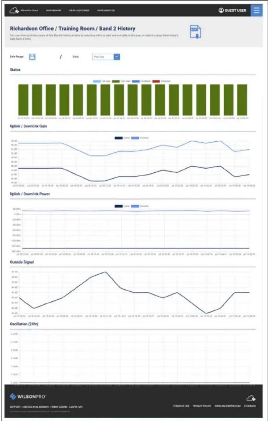
The Band Details table above shows per-Band performance metrics. In addition, Bands can be disabled and re-enabled, as well as viewing the Band History.
WARNING: Disabling bands could disconnect the LTE connection and prevent communication with the cloud.
The Band History screen provides performance and signal level histories.
(WILSONPRO CLOUD cont.)
Alerts & Notifications
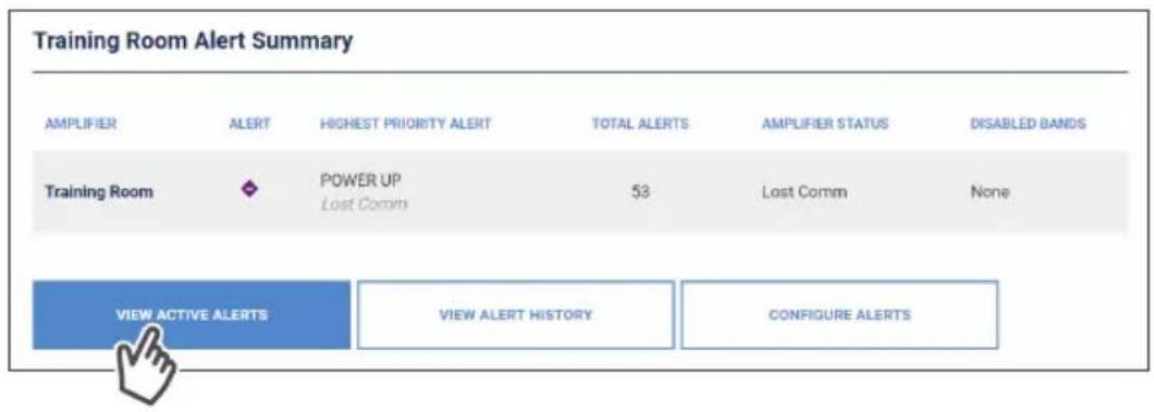
Alerts are displayed on the Location Details screen for all amplifiers for that location. Alerts are also displayed on the Amplifier Details screen for that particular amplifier.
To acknowledge and remove the alert from the lists, choose the alert and click SUBMIT ACKNOWLEDGEMENT.
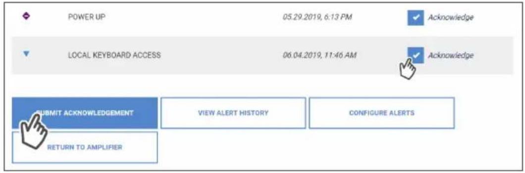
An additional prompt will be displayed indicating alert will be moved to Alert History.
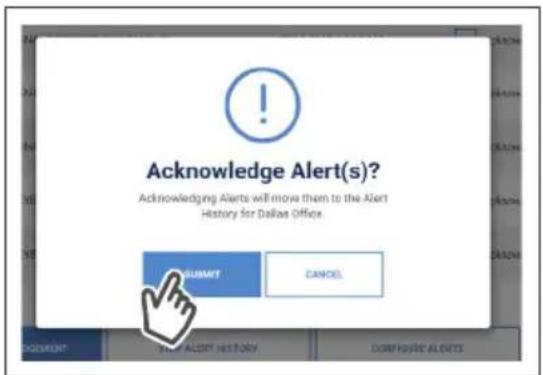
(WILSONPRO CLOUD - ALERTS & NOTIFICATIONS cont.)
To view past alerts that have been removed from the list, click VIEW ALERT HISTORY.
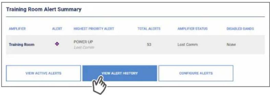
To set which amplifier conditions will result in an alert, click CONFIGURE ALERTS (this can be done from the Amplifier Details screen as well).
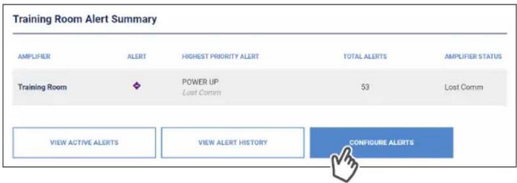
(WILSONPRO CLOUD - ALERTS & NOTIFICATIONS cont.)
Select individual, multiple, or all conditions to change the priority level of all selected alerts, click UPDATE after modifying the conditions. These alerts (which can be set as notifications) and then will be pushed to SMS (text) and email.
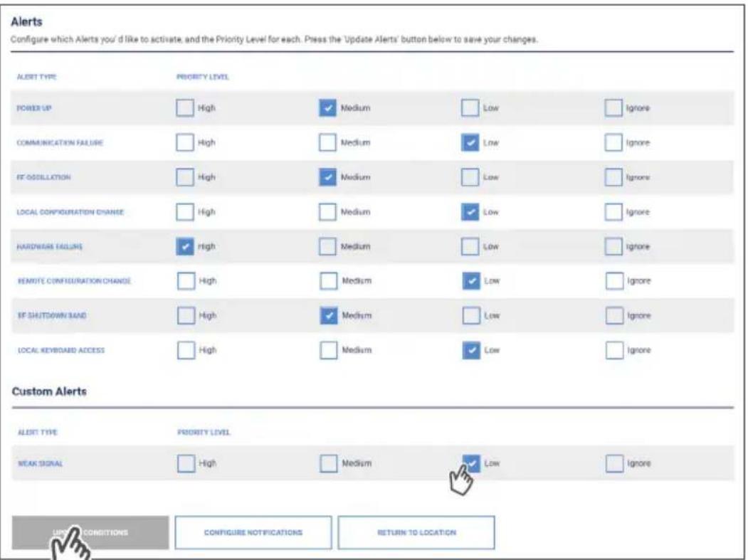
To configure Alert notifications click CONFIGURE NOTIFICATIONS.
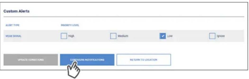
(WILSONPRO CLOUD – ALERTS & NOTIFICATIONS cont.)
You can configure Alert notifications for this Location to be sent to Recipients.
These Recipients can either be Monitors registered in the system, or 'other'
Recipients identified by email or phone. To add or delete Recipients, click on the
+ - . You can also choose which priority level of alerts generates a notification.
Click UPDATE when completed.
Configure Notifications / Wilson Electronics Engineering - Staging / Dallas Office
You can configure Alert notifications for this Location to be sent to recipients. These recipients can either be Monitors registered in the system, or 'other' recipients identified by email or phone. You can also choose which priority level of alerts generates a notification;
Recipients (Monitors)
Select and add Monitor Recipients below to receive Alert notifications. You can also choose how the notifications will be received.
Recipient
Dame Monitor


Priority Level:


Recipient



Priority Level:


Recipients (Other)
Add other recipients below to receive Alert notifications. You can also choose how the notifications will be received.
Add Email Recipients
Email Address:

Priority Level:


Add Text Recipients


Priority Level:






SUPPORT: 1-888-923-4468, MONDAY - FRIDAY 500AM - 5:00PM (MT)
COPYRIGHT © 2016 WELSON ELECTRONICS LLC ALL RIGHTS RESERVED
TORMS OF USE
PRIVACY POLICY
WWW.WILSONPRO.COM
(WILSONPRO CLOUD cont.)
Antenna Tuner Tool
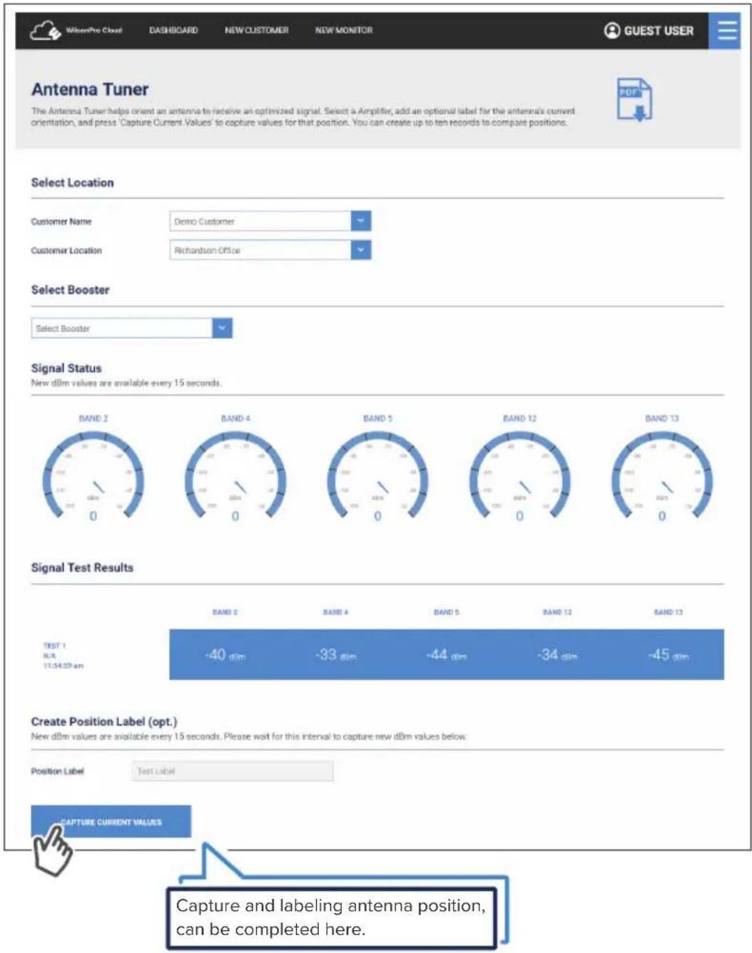
To optimize a signal, you can use the Antenna Tuner Tool to help orient an antenna. Click ANTENNA TUNER from the menu drop down.

(WILSONPRO CLOUD - ANTENNA TUNER TOOL cont.)
The antenna tuner tool allows the integrator/installer to get nearly real time signal information on a handheld device while making outside adjustments to the donor antenna. The antenna tuner tool is refreshed every 10 seconds. Select from the drop-down; Customer, Location, Amplifier and click CAPTURE CURRENT VALUES.
Local Amplifier Configuration Utility
If you need to modify the amplifier communication settings, this utility was created to help you. The default setting is Ethernet Preferred (gives priority to Ethernet, but will switch to LTE if Ethernet is not connected).
NOTE: It is only necessary to use this utility if you wish to CHANGE a communication setting. The default setting of Ethernet preferred, LTE backup, is almost always the best setting to use.
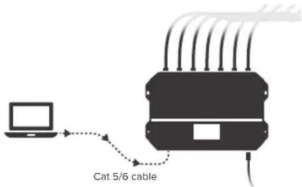
If the Installer/Integrator wishes to change this setting, a laptop computer must be connected to the 4300/4300R via a Cat 5/6 cable to the Ethernet port on the amplifier.
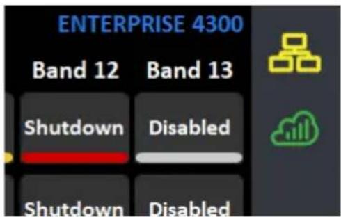
After connecting, the network icon on the amplifier will change color from red to yellow after about one minute.
(LOCAL ETHERNET CONFIGURATION UTILITY cont.)
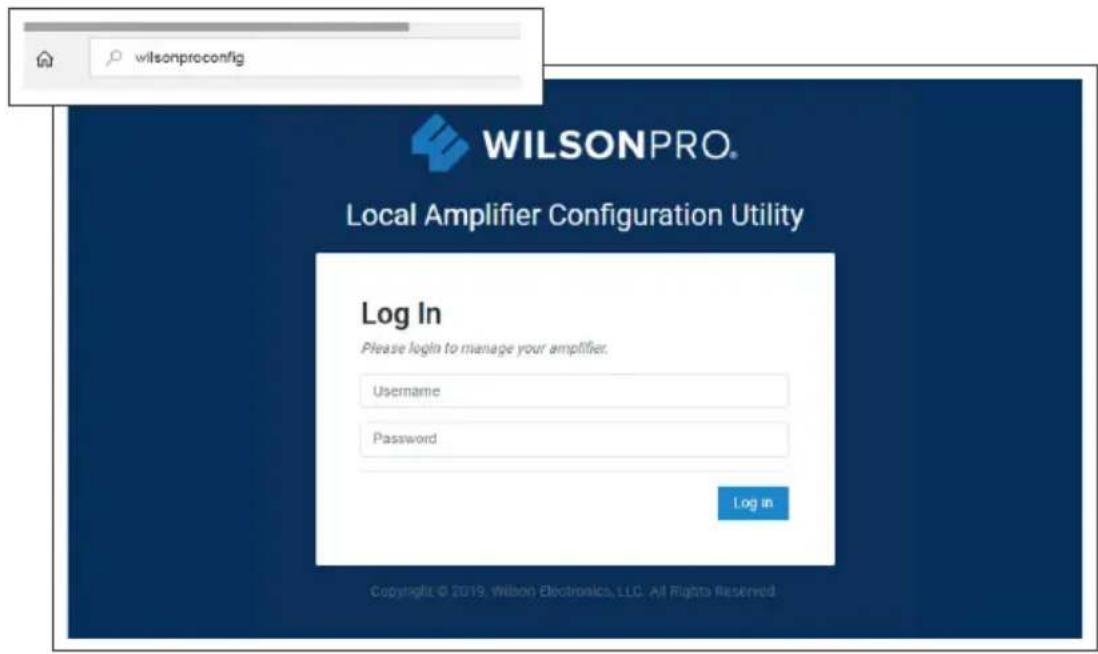
Type wilsonproconfig into the web browser. A login will be displayed, type the following: Username: admin – Password: admin
On the Local Amplifier Configuration Utility page you can select AMPLIFIER, COMMUNICATIONS and SYSTEM to set configurations.
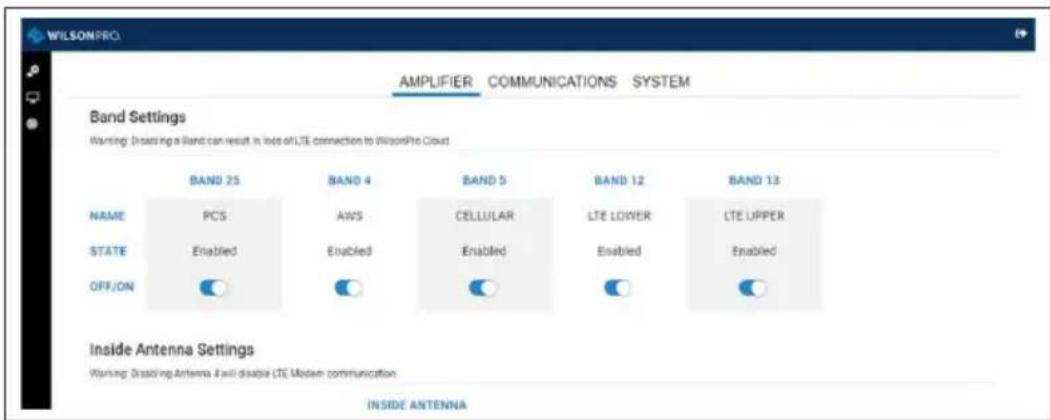
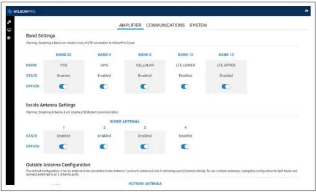
(LOCAL ETHERNET CONFIGURATION UTILITY cont.)
Bands can be turned ON/OFF, you can configure Inside Antenna Settings (ON/OFF) and you can update the Outside Antenna Configuration (COMMON/SPLIT MODE).
Note: Once you make changes to either the Band Enable or Communication Settings, you must wait at least 30 seconds before power cycling the unit or the new settings will not be stored.
You can navigate through the site by clicking on the Settings, Status and Antenna Tuner icons located on the left then selecting AMPLIFIER, COMMUNICATIONS or SYSTEM.
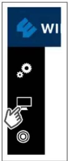

(LOCAL ETHERNET CONFIGURATION UTILITY cont.)
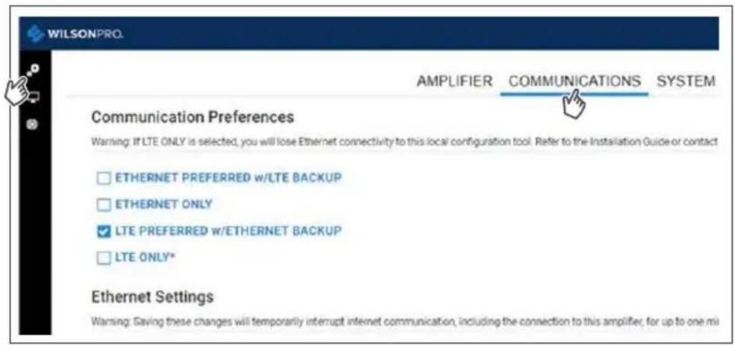
Click on 🙏 then COMMUNICATIONS, Communications Preferences and Ethernet changes can be made here.
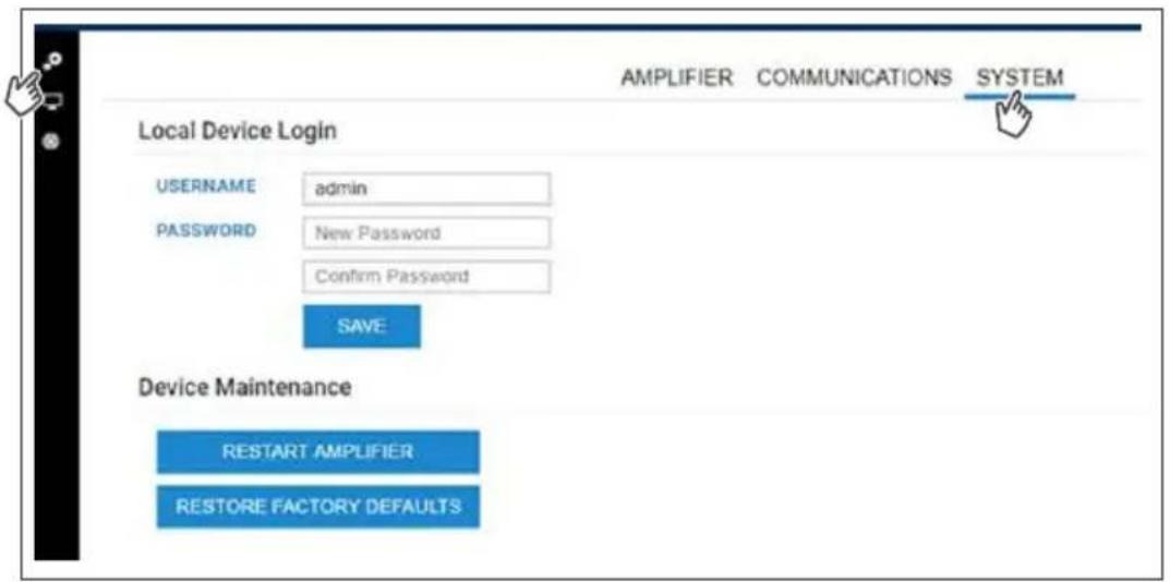
Click on 🎨 then SYSTEM, set password for local amplifier (this password is unrelated to WilsonPro Cloud Service), reboot amplifier and restore system to factory default.
(LOCAL ETHERNET CONFIGURATION UTILITY cont.)
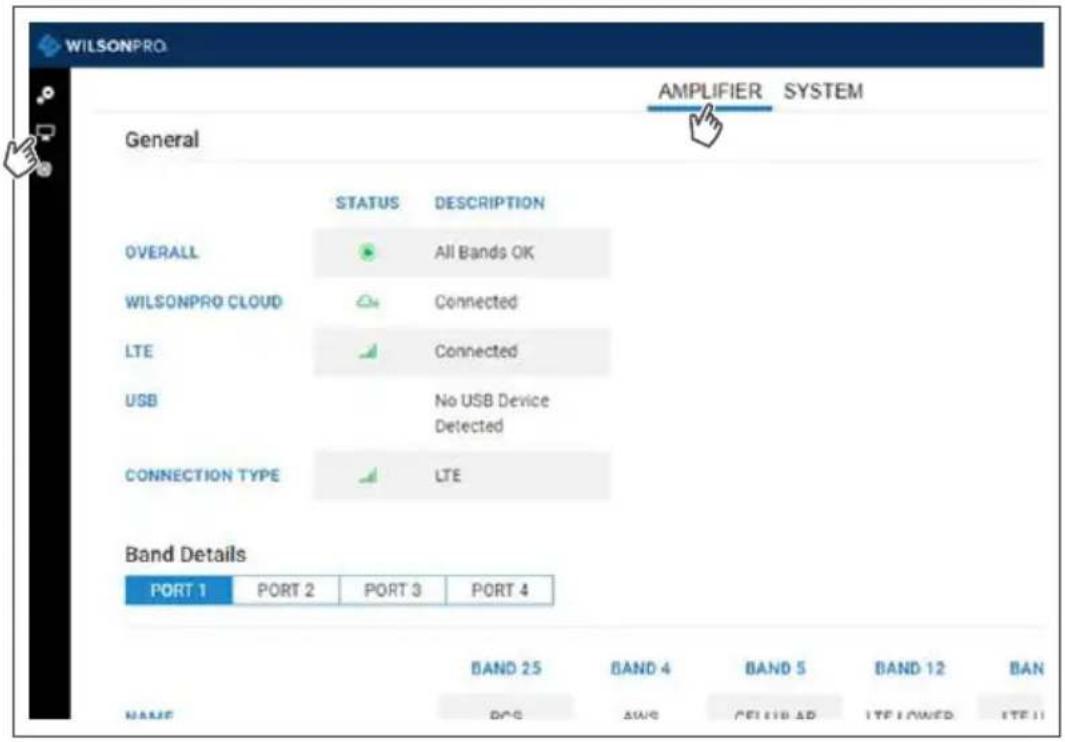
Click on then AMPLIFIER, view overall status of amplifier, WilsonPro Cloud, LTE connection, Ethernet connection, USB connection and power levels for each band.
(LOCAL ETHERNET CONFIGURATION UTILITY cont.)
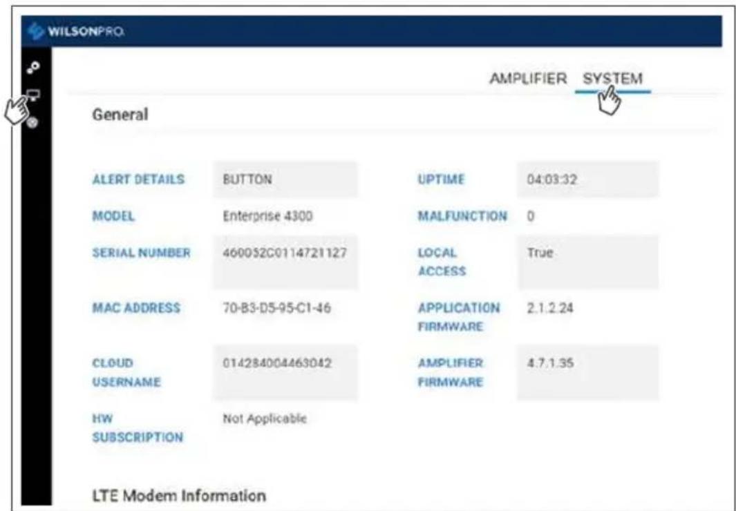
Click on then SYSTEM, view overall system details.
(LOCAL ETHERNET CONFIGURATION UTILITY cont.)
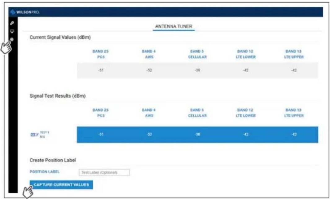
Click on 📄 to use the ANTENNA TUNER to assist with orienting the antenna.
Click CAPTURE CURRENT VALUES and enter an optional label for antenna position to record measurements. These steps can be repeated as many times as you like.
other
ANTENNA TUNER | Signal | BAND 25 PCS | BAND 4 AWS | BAND 5 CELLULAR | BAND 12 LTE LOWER | BAND 13 LTE UPPER | | :--- | :--- | :--- | :--- | :--- | :--- | | Current Signal Values (dBm) | -51 | -52 | -39 | -42 | -42 | | Signal Test Results (dBm) | -51 | -52 | -38 | -42 | -42 | | Create Position Label | POSITION LABEL Test Label (Optional)Notes
NEED HELP?

support.wilsonpro.com 866294.1660
Safety Guidelines

Warnings
To uphold compliance with network protection standards, all active cellular devices must maintain at least 6 feet of separation distance from Panel and Dome antennas.
Use only the power supply provided in this package. Use of a non-Wilson Electronics product may damage your equipment.
The Signal Amplifier unit is designed for use in an indoor, temperature-controlled environment (operating temperature ranges from 0^ C to 45^ C ( 32^ F to 113^ F)). It is not intended for use in attics or similar locations subject to temperatures in excess of that range.
RF Safety Warning: Any antenna used with this device must be located at least 8 inches from all persons.
AWS Warning: The Outside Antenna must be installed no higher than 10 meters (31'9") above ground.
This is a CONSUMER device.
BEFORE USE, you MUST REGISTER THIS DEVICE with your wireless provider and have your provider's consent. Most wireless providers consent to the use of signal boosters. Some providers may not consent to the use of this device on their network. If you are unsure, contact your provider.
In Canada, BEFORE USE you must meet all requirements set out in ISED CPC-2-1-05. You MUST operate this device with approved antennas and cables as specified by the manufacturer. Antennas MUST be installed at least 20 cm (8 inches) from (i.e., MUST NOT be installed within 20 cm of) any person.
You MUST cease operating this device immediately if requested by the FCC (or ISED in Canada) or licensed wireless service provider.
WARNING. E911 location information may not be provided or may be inaccurate for calls served by using this device.
This device may be operated ONLY in a fixed location (i.e..may operate in a fixed location only) for in-building use.
FOR MORE INFORMATION ON REQUIREMENTS SET OUT IN ISED CPC-2-1-05, SEE BELOW:
http://www.ic.gc.ca/eic/site/smt-gst.nsf/eng/sf08942.html
FOR MORE INFORMATION ON REGISTERING YOUR SIGNAL BOOSTER WITH YOUR WIRELESS PROVIDER, PLEASE SEE BELOW:
Sprint: http://www.sprint.com/legal/fcc_boosters.html
T-Mobile/MetroPCS: https://support.t-mobile.com/docs/DOC-9827
Verizon Wireless: http://www.verizonwireless.com/wcms/consumer/register-signal-booster.html
AT&T: https://securec45.securewebsession.com/attsignalbooster.com/
U.S. Cellular: http://www.uscellular.com/uscellular/support/fcc-booster-registration.jsp
Kit Components
The following accessories are certified by the FCC to be used with the
ENTERPRISE 4300/4300R.
This radio transmitter 4726A-460052 / 4726A-460053 has been approved by Innovation, Science and Economic Development Canada to operate with the antenna types listed below, with the maximum permissible gain indicated. Antenna types not included in this list that have a gain greater than the maximum gain indicated for any type listed are strictly prohibited for use with this device.
| B12/17 B13 | B5 B4 B25/2 | ||||
| Outside antenna maximum permissible antenna gain less coax loss (dBi) 50Ω | 3.576 3.21 | 3.012 2.048 | 1.918 | ||
| Inside antenna maximum permissible antenna gain less coax loss (dBi) 50Ω | -2.43 -1.69 | -3.09 -0.33 | -1.29 |
314411
Wide Band Directional Antenna (Outside Antenna)
952300
100 ft. Wilson400 Cable (for Outside Antenna)
304412
Dome Antenna (Inside antennas)
952300
100 ft. Wilson400 Cable (for Inside Antennas)
859902
50 Ohm Lightning Surge Protector
952302
2 ft. Wilson400 Cable
All equivalent or lesser antennas and cables are suitable for use with 4300/4300R signal boosters.
Specifications
| Model Number 460152 / 460153 | |||||
| FCC ID | PWO460052 / PWO460053 | ||||
| IC ID | 4726A-460052 / 4726A-460053 | ||||
| Connectors N-Connectors | |||||
| Antenna Impedance 50 Ohms | |||||
| Frequency | 698-716 MHz, 729-756 MHz, 777-787 MHz, 824-894 MHz, 1850-1995 MHz, 1710-1755/2110-2155 MHz | ||||
| Power output for single cell phone (Uplink) dBm | 700MHzBand12/17 | 700MHzBand13 | 800MHzBand 5 | 1700MHzBand 4 | 1900MHzBand 25/2 |
| 22.9 23.1 24.6 22.8 25.5 | |||||
| Power output for single cell phone (Downlink) dBm | 700MHzBand12/17 | 700MHzBand13 | 800MHzBand 5 | 2100MHzBand 4 | 1900MHzBand 25/2 |
| 16.9 16.7 16.8 16.6 16.6 | |||||
| Noise Figure 5 dB nominal | |||||
| Isolation >90 dB | |||||
| Power Requirements | 120V AC 0.5A | ||||
The term "IC" before the radio certification number only signifies that Industry Canada technical specifications were met.
Each Signal Amplifier is individually tested and factory set to ensure FCC compliance. The Amplifier cannot be adjusted without factory reprogramming or disabling the hardware. The Signal Amplifier will amplify, but not alter incoming and outgoing signals in order to increase coverage of authorized frequency bands only. If the Signal Amplifier is not in use for five minutes, it will reduce gain until a signal is detected. If a detected signal is too high in a frequency band, or if the Signal Amplifier detects an oscillation, the Signal Amplifier will automatically turn the power off on that band. For a detected oscillation the Signal Amplifier will automatically resume normal operation after a minimum of 1 minute. After 5 (five) such automatic restarts, any problematic bands are permanently shut off until the Signal Amplifier has been manually restarted by momentarily removing power from the Signal Amplifier. Noise power, gain, and linearity are maintained by the Signal Amplifier's microprocessor.
This device complies with Part 15 of FCC rules. Operation is subject to two conditions: (1) This device may not cause harmful interference, and (2) this device must accept any interference received, including interference that may cause undesired operation. Changes or modifications not expressly approved by Wilson Electronics LLC could void the authority to operate this equipment.
This device contains licence-exempt transmitter(s)/receiver(s) that comply with Innovation, Science and Economic Development Canada's licence-exempt RSS(s). Operation is subject to the following two conditions: (1) This device may not cause interference, and (2) This device must accept any interference, including interference that may cause undesired operation of the device. Changes or modifications not expressly approved by Wilson Electronics LLC could void the authority to operate this equipment.
NEED HELP?

support.wilsonpro.com 866294.1660
Warranty

30 DAY MONEY-BACK GUARANTEE
All WilsonPro products are protected by WilsonPro 30-day money-back guarantee. If for any reason the performance of any product is not acceptable, simply return the product directly to the reseller with a dated proof of purchase.

3 YEAR WARRANTY
WilsonPro Amplifiers are warranted for three (3) years against defects in workmanship and/or materials. Warranty cases may be resolved by returning the product directly to the reseller with a dated proof of purchase.
Signal Amplifiers may also be returned directly to the manufacturer at the consumer's expense, with a dated proof of purchase and a Returned Material Authorization (RMA) number supplied by WilsonPro. WilsonPro shall, at its option, either repair or replace the product.
This warranty does not apply to any Signal Amplifiers determined by WilsonPro to have been subjected to misuse, abuse, neglect, or mishandling that alters or damages physical or electronic properties.
Replacement products may include refurbished WilsonPro products that have been recertified to conform with product specifications.
RMA numbers may be obtained by contacting Customer Support.
DISCLAIMER: The information provided by WilsonPro is believed to be complete and accurate. However, no responsibility is assumed by WilsonPro for any business or personal losses arising from its use, or for any infringements of patents or other rights of third parties that may result from its use.
MARKETING APPROVAL: Installer and end customer hereby grants to Wilson Electronics the express right to use installers or end customers company logo in marketing, sales, financial, and public relations materials and other communications solely to identify Customer as a Wilson Electronics customer.

WILSONPRO™
A Wilson Electronics Brand


3301 East Deseret Drive, St. George, UT
www.wilsonpro.com | support.wilsonpro.com
Copyright © 2019 Wilson Electronics. All rights reserved.
Wilson Electronics products covered by U.S. patent(s) and pending application(s)
For patents go to: weboost.com/us/patents
- Index
- Package Contents
- Enterprise 4300 SKU 460152
- Enterprise 4300R SKU 460153
- Enterprise 4300 & 4300R
- Additional Features
- Installation Diagram
- Split Mode
- Common Mode
- Post-Install Setup
- Menu System
- Band Menu Color Description
- Settings Screen
- Cloud Communication Settings Tab
- Antenna Settings Tab
- Split-Mode Configuration
- Band-Status Screens
- Connectivity Status Screens
- WilsonPro Cloud
- The cloud-based platform for remote monitoring & control of cellular signal amplifiers
- Logging into the WilsonPro Cloud via Ethernet
- Customer Dashboard
- Adding a Customer
- (WILSONPRO CLOUD - ADDING A CUSTOMER cont.)
- Creating an Additional Customer Location
- Add Additional Location
- Location
- Adding an Amplifier
- Look Up Details (QR Code)
- Amplifier Metrics
- Alerts & Notifications
- (WILSONPRO CLOUD - ALERTS & NOTIFICATIONS cont.)
- (WILSONPRO CLOUD – ALERTS & NOTIFICATIONS cont.)
- Configure Notifications / Wilson Electronics Engineering - Staging / Dallas Office
- Recipients (Monitors)
- Recipients (Other)
- Antenna Tuner Tool
- (WILSONPRO CLOUD - ANTENNA TUNER TOOL cont.)
- Local Amplifier Configuration Utility
- (LOCAL ETHERNET CONFIGURATION UTILITY cont.)
- Notes
- Safety Guidelines
- Warnings
- This is a CONSUMER device.
- FOR MORE INFORMATION ON REQUIREMENTS SET OUT IN ISED CPC-2-1-05, SEE BELOW:
- FOR MORE INFORMATION ON REGISTERING YOUR SIGNAL BOOSTER WITH YOUR WIRELESS PROVIDER, PLEASE SEE BELOW:
- Kit Components
- ENTERPRISE 4300/4300R.
- 314411
- 952300
- 304412
- 859902
- 952302
- Specifications
- Warranty
- DAY MONEY-BACK GUARANTEE
- YEAR WARRANTY
- WILSONPRO™
Brand : Wilson
Model : Enterprise 4300R
Category : TV amplifier