WeBoost RV Antenna - TV amplifier Wilson - Free user manual and instructions
Find the device manual for free WeBoost RV Antenna Wilson in PDF.


| Product Type | Outdoor TV/Cellular Antenna with Amplifier |
| Brand | Wilson Electronics (weBoost) |
| Model | Drive RV Antenna (311230) |
| Dimensions | 7.422 x 2.688 in (188 x 68 mm) |
| Weight | 0.40 lb (0.181 kg) |
| Connector Type | SMA Female |
| Frequency Bands | 698-806, 806-960, 1710-1880, 1850-1990, 1910-2170, 2300-2700 MHz |
| Peak Gain | Up to 4.3 dBi (varies by band) |
| Impedance | 50 Ω |
| Maximum Power | 10 W |
| Polarization | Vertical |
| IP Rating | IP66 (weatherproof) |
| Mounting Type | CB antenna mount, 3-way mirror rail mount included |
| Cable Length | 25 ft (7.6 m) LMR-195 |
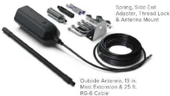
| Included Accessories | Antenna, 25 ft cable, 13 in mast extension, spring, side exit adapter, antenna mount, thread lock |
| Configurable Height | Adjustable from 7.5 to 20.5 inches |
| Ruggedness | MIL-STD-810H certified (shock & vibration) |
| Safety Compliance | RF safety: keep 8 in from persons; max install height 32 ft 9 in |
| Warranty | 2 years |
| Country of Assembly | USA |
| Radome Material | ASA (Acrylonitrile Styrene Acrylate) |
| Rated Wind Velocity | 311 mph (500 kph) |
Frequently Asked Questions - WeBoost RV Antenna Wilson
User questions about WeBoost RV Antenna Wilson
0 question about this device. Answer the ones you know or ask your own.
Ask a new question about this device
Download the instructions for your TV amplifier in PDF format for free! Find your manual WeBoost RV Antenna - Wilson and take your electronic device back in hand. On this page are published all the documents necessary for the use of your device. WeBoost RV Antenna by Wilson.
USER MANUAL WeBoost RV Antenna Wilson
natural_image
Technical line drawing of a medical device with a vertical rod, a bulb, and two connectors (no text or symbols)Drive RV Antenna
Index
Package Contents ....1
Select Mounting Location 2
Assemble the Antenna 3
Mounting the Antenna 5
Safety Guidelines & Specifications 6
Warranty 7
Package Contents
natural_image
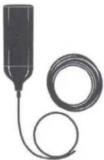
Illustration of a medical or laboratory device with a cylindrical tube and coiled cable (no text or symbols)Drive RV Antenna w/25 ft. Cable (311230)

13 in. Mast Extension
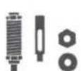
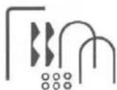
Spring, Side Exit
Adapter & Antenna
Mount

Thread Lock
Select Mounting Location
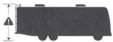
Mount Outside Antenna to a ladder or pole, so that the entire Outside Antenna is above the roof line of the RV and clear of other metal obstructions. We recommend doing a 'soft install', verifying the system works as desired, before permanently installing the kit.
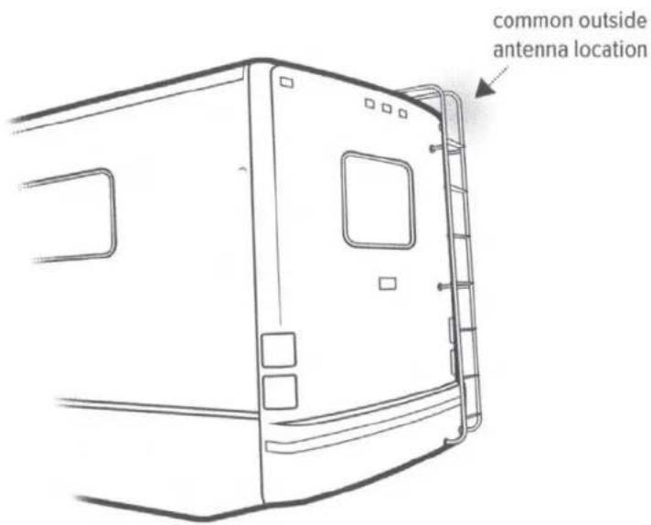
NOTE: Keep in mind to stay below the maximum height limit allowed by law, which varies from state to state (generally 14 ft. in western states and 13 ft.6 in. in eastern states.
natural_image
Silhouette of a vehicle with warning sign and height dimension (no text or symbols)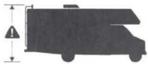
natural_image
Silhouette of a truck with an exclamation mark and downward arrow, no text or symbols present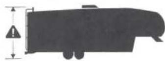
natural_image
Silhouette of a vehicle with a warning sign and height dimension (no text or symbols)Assemble the Antenna
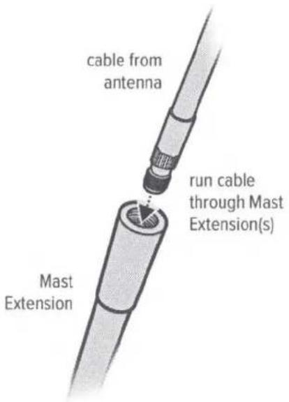
Once you have determined the best location for the antenna, insert cable through mast(s) then through Side Exit Adpater.
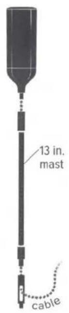
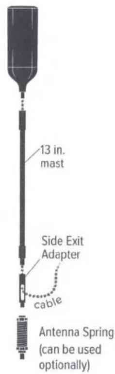
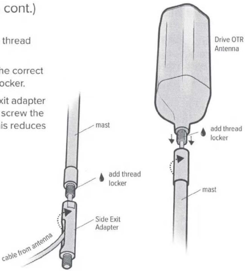
(Assemble the Antenna cont.)
Use thread locker (provided) to thread points and screw into place.
NOTE: Be sure the antenna is the correct height before applying thread locker.
NOTE: When adding the side exit adapter hold the antenna vertically and screw the adapter from the bottom up. This reduces cable twisting.
Mounting the Antenna
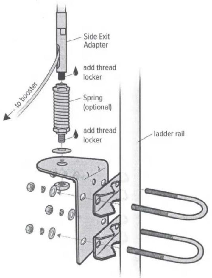
Mount to ladder rail on RV as shown and route cable into RV then connect cable to the booster. The system performs best with maximum vertical and horizontal separation.
NOTE: If installing with Spring, the Side Exit Adapter must be used.
Safety Guidelines & Specifications
RF Safety Warning: Any antenna used with this device must be located at least 8 inches from all persons. AWS Warning: The Outside Antenna must be installed no higher than 32 feet 9 inches (10 meters) above ground.
| Electrical Specifications | ||||||
| Frequency Band (MHz) | 698-806 | 806-960 | 1710-1880 | 1850-1990 | 1910-2170 | 2300-2700 |
| Peak Gain (dBi) | 2.4 | 2.6 | 3.8 | 3.8 | 3.7 | 4.3 |
| Gain (dBi), Typical @ 2° Elevation | 1.4 | 2.4 | 3.1 | 2.7 | 2.4 | 2.6 |
| Cable loss LMR-195 30 in. | 0.3 | 0.3 | 0.5 | 0.5 | 0.5 | 0.6 |
| VSWR | <2:1 | <2:1 | ||||
| Efficiency (%) | >70 | >65 | ||||
| Polarization | Vertical | |||||
| Half-Power Azimuth Beamwidth (°) | 360 | 360 | 360 | 360 | 360 | 360 |
| Half-Power Elevation Beamwidth (°) | 70 | 78 | 60 | 70 | 80 | 33 |
| Impedance (Ω) | 50 | |||||
| Maximum Power (W) | 10 | |||||
| Mechanical Specifications | |
| Model | 311230 |
| Connector | SMA (F) |
| Dimensions (in / mm) | 7.422 x 2.688 / 188 x 68 |
| Weight (lb / kg) | .40 / 0.181 |
| Rated Wind Velocity (mph / kph) | 311 / 500 |
| Radiator Material | Aluminum |
| Radome Material | Alumin Plastic Type: ASA (Acrylonitrile Styrene) Acrylate) |

2 YEAR WARRANTY
Antennas may also be returned directly to the manufacturer at the consumer's expense, with a dated proof of purchase and a Returned Material Authorization (RMA) number supplied by Wilson Electronics. Wilson Electronics shall, at its option, either repair or replace the product. Wilson Electronics will pay for delivery of the repaired or replaced product back to the original consumer if located within the continental U.S.
Replacement products may include refurbished Wilson Electronics products that have been recertified to conform with product specifications.
This warranty does not apply to any antennas determined by Wilson Electronics to have been subjected to misuse, abuse, neglect, or mishandling that alters or damages physical or electronic properties.
RMA numbers may be obtained by contacting Technical Support at 866-294-1660.
DISCLAIMER: The information provided by Wilson Electronics, LLC is believed to be complete and accurate. However, no responsibility is assumed by Wilson Electronics, LLC for any business or personal losses arising from its use, or for any infringements of patents or other rights of third parties that may result from its use.
MARKETING APPROVAL: Installer and end customer hereby grants to Wilson Electronics the express right to use installers or end customers company logo in marketing, sales, financial, and public relations materials and other communications solely to identify Customer as a Wilson Electronics customer.

WILSON
ELECTRONICS


3301 East Deseret Drive, St. George, UT

866.294.1660

www.wilsonelectronics.com

support@wilsonelectronics.com
Copyright © 2020 Wilson Electronics. All rights reserved. Wilson Electronics products covered by U.S. patent(s) and pending application(s). For patents go to: weboost.com/us/patents
NOT AFFILIATED WITH WILSON ANTENNA
GDE000300_Rev01_08.10.20
Drive RV Antenna
SKU: 311230
MAP: \$99.99
FEATURES
• Covers 700, 800, 1700, 1900, 2200 MHz cellular
• All modes, voice and data
• High gain signal output
- Antenna can be configured into multiple lengths from 7.5 - 20.5 in.
• Off-road rated to MIL-STD 810H for shock and vibration
• Works with standard CB antenna mounts, includes 3-way mirror rail mount
- Connects to mobile cellular boosters
• IP66 rated for outdoor use
- Assembled in USA
• 2 year warranty
WARNING: This product can expose you to chemicals including Nickel, which is known to the State of California to cause cancer, and Bisphenol A, which is known to the State of California to cause birth defects or other reproductive harm. For more information go to www.P65Warnings.ca.gov
Specifications
ELECTRICAL
| Frequency Band (MHz) | 698-806 | 806-960 | 1710-1880 | 1850-1990 | 1910-2170 | 2300-2700 |
| Peak Gain (dBi) | 2.4 | 2.6 | 3.8 | 3.8 | 3.7 | 4.3 |
| Gain (dBi), typical @ 2" Elevation | 1.4 | 2.4 | 3.1 | 2.7 | 2.4 | 2.6 |
| Cable loss LMR-195.30 in. | 0.3 | 0.3 | 0.5 | 0.6 | ||
| Efficiency (%) | >70% | >65% | ||||
| VSWR | <2.1 | <2.1 | ||||
| Polarization | Vertical | |||||
| Hall-Power Azimuth Beamwidth (°) | 360 | 360 | 360 | 360 | 360 | 360 |
| Hall-Power Elevation Beamwidth (°) | 70 | 78 | 60 | 70 | 80 | 33 |
| Impedance (Ω) | 50 | |||||
| Max Power (W) | 10 | |||||
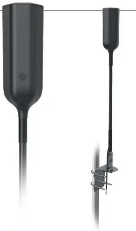
natural_image
Two black medical or laboratory devices with tubing, one upright and one vertical, against a white background (no visible text or symbols)Kit Includes
MECHANICAL
| Model | 311230 |
| Connector | SMA Male / SMB Plug |
| Feed Cable Length (in / mm) | 30 / 762 |
| Dimensions (in / mm) | 7.422x2.688 / 188x68 |
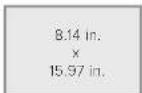
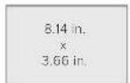
| Packaged Dimensions (in / mm) | 8.14 x15.97x3.66 / 206x406x93 |
| Packaged Weight (lb / kg) | 3.64 / 1.65 |
| Wind Loading Area (ft2/m2) | 246 ft^2 / .0229m^2 |
| Rated Wind Velocity (mph/kph) | 311 / 500k |
| Radiator Material | Aluminum |
| Radome Material | Alumin Plastic Type: ASA (Acrylonitrile Styrene Acrylate) |
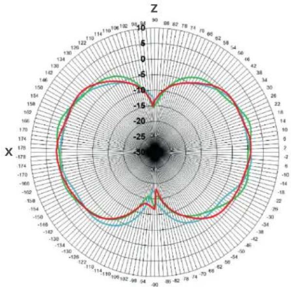
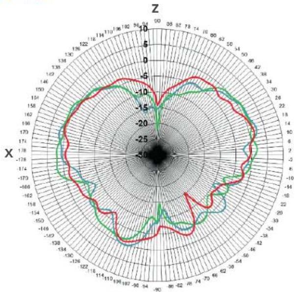
Radiation Patterns, 700-900 MHz
700 MHz 800 MHz 900 MHz
E Plane
radar
| Angle | Red Line | Green Line | Cyan Line | |-------|----------|------------|-----------| | 0 | -15 | -10 | -25 | | 30 | -10 | -5 | -20 | | 60 | -5 | 0 | -15 | | 90 | 0 | 5 | -10 | | 120 | 5 | 10 | -5 | | 150 | 10 | 15 | 0 | | 180 | 15 | 20 | 5 | | 210 | 20 | 25 | 10 | | 240 | 25 | 30 | 15 | | 270 | 30 | 35 | 20 | | 300 | 35 | 40 | 25 | | 330 | 40 | 45 | 30 | | 360 | 45 | 50 | 35 | | 390 | 50 | 55 | 40 | | 420 | 55 | 60 | 45 | | 450 | 60 | 65 | 50 | | 480 | 65 | 70 | 55 | | 510 | 70 | 75 | 60 | | 540 | 75 | 80 | 65 | | 570 | 80 | 85 | 70 | | 600 | 85 | 90 | 75 | | 630 | 90 | 95 | 80 | | 660 | 95 | 100 | 85 | | 690 | 100 | 105 | 90 | | 720 | 105 | 110 | 95 | | 750 | 110 | 115 | 100 | | 780 | 115 | 120 | 105 | | 810 | 120 | 125 | 110 | | 840 | 125 | 130 | 115 | | 870 | 130 | 135 | 120 | | 900 | 135 | 140 | 125 | | 930 | 140 | 145 | 130 | | 960 | 145 | 150 | 135 | | 990 | 150 | 155 | 140 | | 1020 | 155 | 160 | 145 | | 1050 | 160 | 165 | 150 | | 1080 | 165 | 170 | 155 | | 1110 | 170 | 175 | 160 | | 1140 | 175 | 180 | 165 | | 1170 | 180 | 185 | 170 | | 1200 | 185 | 190 | 175 | | 1230 | 190 | 195 | 180 | | 1260 | 195 | 200 | 185 | | 1290 | 200 | 205 | 190 | | 1320 | 205 | 210 | 195 | | 1350 | 210 | 215 | 200 | | 1380 | 215 | 220 | 205 | | 1410 | 220 | 225 | 210 | | 1440 | 225 | 230 | 215 | | 1470 | 230 | 235 | 220 | | 1500 | 235 | 240 | 225 | | Note: The data for 'Red' and 'Green' are not explicitly provided in the code. The 'X' label indicates which the data point corresponds to the axis of the plot. The 'Z' label indicates which the plot is a dimension of the x-axis. There is no additional data series in this case. The y-axis labels are the same as 'X' but differ in direction and magnitude based on the color scheme. The values for 'Red' and 'Green' are estimated based on the plot's visual scale. There is only one data series represented by the colored markers. The y-axis is labeled 'X'.
H Plane
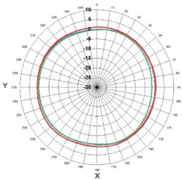
radar
| Angle | Value | |-------|-------| | 0 | 0 | | 30 | 0 | | 60 | 0 | | 90 | 0 | | 120 | 0 | | 150 | 0 | | 180 | 0 | | 210 | 0 | | 240 | 0 | | 270 | 0 | | 300 | 0 | | 330 | 0 | | 360 | 0 |Radiation Patterns, 1700-2100 MHz
1700 MHz 1900 MHz 2100 MHz
E Plane
radar
| Angle | Red Line Value | Green Line Value | |-------|----------------|------------------| | 0 | -5 | -10 | | 30 | -10 | -15 | | 60 | -15 | -20 | | 90 | -20 | -25 | | 120 | -25 | -30 | | 150 | -30 | -35 | | 180 | -35 | -40 | | 210 | -40 | -45 | | 240 | -45 | -50 | | 270 | -5 | -55 | | 300 | -5 | -60 | | 330 | -5 | -65 | | 360 | -5 | -70 |H Plane
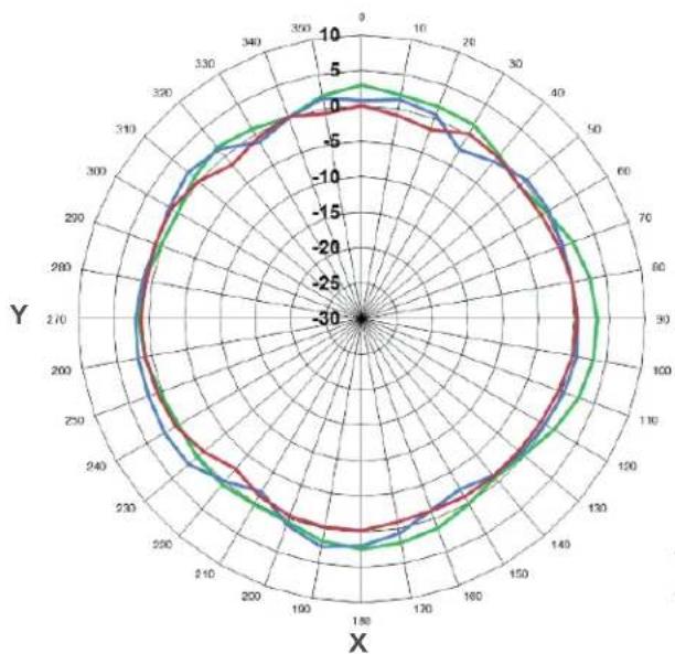
radar
| Angle | Red Line | Green Line | Blue Line | |-------|----------|------------|-----------| | 0 | 0 | 5 | 0 | | 30 | -5 | 0 | -5 | | 60 | -10 | -5 | -10 | | 90 | -15 | -10 | -15 | | 120 | -20 | -15 | -20 | | 150 | -25 | -20 | -25 | | 180 | -30 | -25 | -30 | | 210 | -25 | -20 | -25 | | 240 | -20 | -15 | -20 | | 270 | -15 | -10 | -15 | | 300 | -10 | -5 | -10 | | 330 | -5 | 0 | -5 | | 360 | 0 | 5 | 0 |Radiation Patterns, 2300-2700 MHz
2300 MHz 2500 MHz 2700 MHz
E Plane
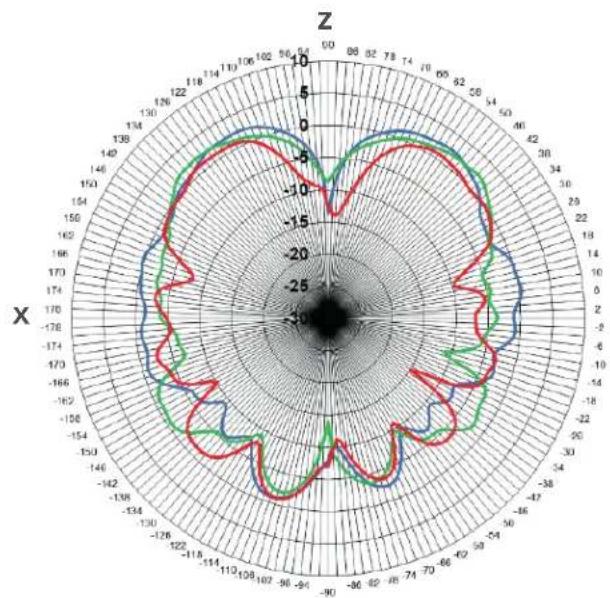
radar
| Angle | Value | |-------|-------| | 0° | -10 | | 30° | -5 | | 60° | 0 | | 90° | 5 | | 120° | 10 | | 150° | 5 | | 180° | 0 | | 210° | -5 | | 240° | -10 | | 270° | -5 | | 300° | 0 | | 330° | 5 | | 360° | 10 |H Plane
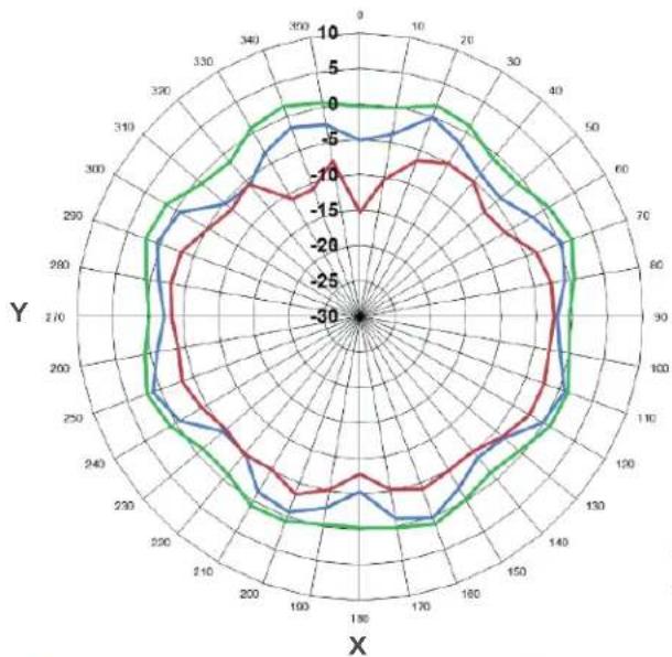
radar
| Angle | Red Line | Blue Line | Green Line | |-------|----------|-----------|------------| | 0 | -15 | -5 | 0 | | 30 | -10 | -5 | 5 | | 60 | -10 | -5 | 5 | | 90 | -10 | -5 | 5 | | 120 | -10 | -5 | 5 | | 150 | -10 | -5 | 5 | | 180 | -10 | -5 | 5 | | 210 | -10 | -5 | 5 | | 240 | -10 | -5 | 5 | | 270 | -10 | -5 | 5 | | 300 | -10 | -5 | 5 | | 330 | -10 | -5 | 5 | | 360 | -10 | -5 | 5 |Note: Gain values at 2^ elevation indicated are without cable loss. Please refer to the electrical specs chart to include cable losses.
Peak Gain (@ 2° Elevation)
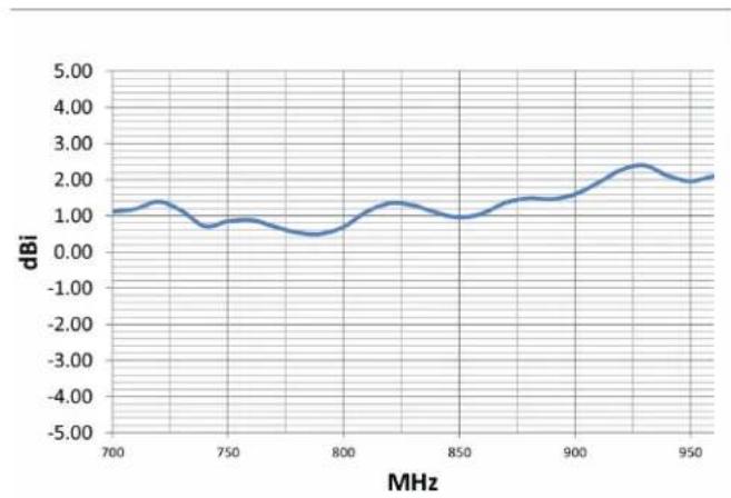
line
| MHz | dBi | | ---- | ---- | | 700 | 1.00 | | 750 | 0.80 | | 800 | 0.60 | | 850 | 1.00 | | 900 | 1.50 | | 950 | 2.00 |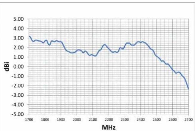
line
| MHz | dBi | | ---- | ---- | | 1700 | 3.00 | | 1800 | 2.80 | | 1900 | 2.60 | | 2000 | 1.80 | | 2100 | 1.50 | | 2200 | 2.20 | | 2300 | 2.50 | | 2400 | 2.70 | | 2500 | 1.50 | | 2600 | -0.50 | | 2700 | -2.50 |Efficiency (%)
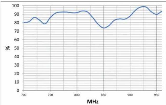
line
| MHz | % | | ---- | --- | | 700 | 80 | | 750 | 78 | | 800 | 92 | | 850 | 73 | | 900 | 88 | | 950 | 92 |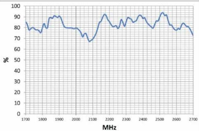
line
| MHz | % | | ---- | --- | | 1700 | 85 | | 1800 | 78 | | 1900 | 90 | | 2000 | 78 | | 2100 | 68 | | 2200 | 92 | | 2300 | 85 | | 2400 | 90 | | 2500 | 95 | | 2600 | 80 | | 2700 | 75 |Note: Gain values at 2^ elevation indicated are without cable loss. Please refer to the electrical specs chart to include cable losses.
Package Dimensions
8.14 W × 15.97 L × 3.66 D
FRONT

SIDE TOP/BOTTOM WEIGHT

FOR PARTNER'S USE

311230_DriveRVAntenna_SpecSheet_Rev03_10.15.20
Support

2 Year Warranty
Email: support@wilsonelectronics.com
Website: http://support.weboost.com
Phone: +1 866 294 1660 Monday to Saturday
* WARNING: Cancer and Reproductive Harm - www.P65Warnings.ca.gov.
ASSEMBLED IN THE USA

UPC

Brand : Wilson
Model : WeBoost RV Antenna
Category : TV amplifier