AMPIC5 - Loudspeaker OWI - Free user manual and instructions
Find the device manual for free AMPIC5 OWI in PDF.

| Product Type | Self-amplified in-ceiling speaker |
| Model | AMPIC5 |
| Speaker Size | 5.25 inches (IC5 compatible) |
| Maximum Power Output | 25 Watts |
| Frequency Response | 50 Hz – 15 kHz |
| Total Harmonic Distortion (THD) | < 0.1% |
| Signal-to-Noise Ratio (S/N) | > 90 dB |
| Input Configuration | Differential (balanced/unbalanced) |
| Common Mode Rejection | Minimum 40 dB |
| Nominal Load Impedance | 8 ohms (speaker) |
| Minimum Load Impedance | 3.2 ohms |
| Input Load Impedance | 10 kΩ |
| Amplifier Type | Class AB |
| Protection Features | Short circuit, overheat, overcurrent |
| Power Supply | 12 V AC (UL listed power supply included) |
| Maximum Daisy-Chain | Up to 20 self-amplified speakers |
| Cut-Out Size | 6 5/8 inches (168 mm) diameter |
| Mounting Depth | 2 3/4 inches (70 mm) |
| Enclosure Material | Plastic fire-rated V-0 |
| Grille Material | Aluminum |
| Warranty | 1 year (self-amplified module) |
| Cleaning Instructions | Clean only with dry cloth |
Frequently Asked Questions - AMPIC5 OWI
User questions about AMPIC5 OWI
0 question about this device. Answer the ones you know or ask your own.
Ask a new question about this device
Download the instructions for your Loudspeaker in PDF format for free! Find your manual AMPIC5 - OWI and take your electronic device back in hand. On this page are published all the documents necessary for the use of your device. AMPIC5 by OWI.
USER MANUAL AMPIC5 OWI
Installation Instructions
Models AMPIC5 / AMPIC6
( Speaker Combination Models AMP1S51 / AMP1S52 / AMP1S54
AMP1S61 / AMP1S62 / AMP1S64 )
SELF-AMPLIFIED IN-CEILING SPEAKERS (SINGLE INPUT/SOURCE)
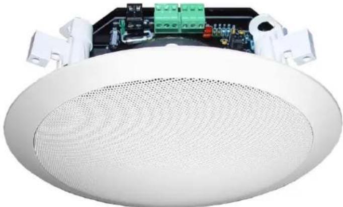
natural_image
White circular ceiling fan with visible circuit board and electronic components (no text or symbols)


Established 1978
OWI Incorporated
17141 Kingsview Ave. Carson CA 90746-1207 USA
Tel. 310-515-1900 * Fax 310-515-1606
info@owi-inc.com
www.owi-inc.com
Technical Support: 310-515-1900
Table of Contents
| Important Safety Instructions | Page 3 to 4 |
| Introduction | Page 5 |
| Specification – Self Amplified Speakers Models AMPIC5 / AMPIC6 | Page 5 |
| Module – Self Amplified Speakers Models AMPIC5 / AMPIC6 | Page 6 to 7 |
| One Amplified Speaker Wiring Diagram – AMP1S51 / AMP1S61 | Page 8 |
| Two Speaker Combination Wiring Diagram – AMP1S52 / AMP1S62 | Page 9 |
| Four Speaker Combination Wiring Diagram – AMP1S54 / AMP1S64 | Page 10 |
| Wiring Diagram – Self Amplified Speaker to another Self Amplified Speaker | Page 11 |
| Trouble Shooting Guide | Page 12 |
| Limited Warranty Information – AMPIC5 / AMPIC6 | Page 12 |
| Warranty Card | Page 13 |
| Drywall/Stucko/Sheet Rocks In-ceiling Speaker Installation | Page 14 |
| Tee Bar In-ceiling Speaker Installation | Page 15 |
| IC5 / IC6 (Non Amplified Speaker) Specifications | Page 16 |
| In-ceiling Speakers Mounting Instructions | Page 16 to 18 |
| Warranty Information – IC5 / IC6 (Non-amplified Speakers) | Page 19 |
| Self Amplified Speaker Combination Program | Back Cover |

CAUTION RISK OF ELECTRIC SHOCK
DO NOT OPEN

CAUTION: TO REDUCE THE RISK OF ELECTRIC SHOCK DO NOT REMOVE COVER (OR BACK) NO USER-SERVICEABLE PARTS INSIDE REFER SERVICING TO QUALIFIED PERSONNEL

The lightning flash with arrowhead symbol within an equilateral triangle is intended to alert the user to the presence of uninsulated "dangerous voltage" within the product's enclosure that may be of sufficient magnitude to constitute a risk of electric shock to persons.

The exclamation point within an equilateral triangle is intended to alert the user of the presence of important operating and maintenance (servicing) instructions in the literature accompanying the appliance.
The apparatus shall not be exposed to dripping or splashing and that no objects filled with liquids, such as vases, shall be placed on the apparatus.
IMPORTANT SAFETY INSTRUCTIONS
- Read these instructions - All the safety and operation instructions should be read before this OWI product is operated.
- Keep these instructions - The safety and operating instructions should be kept for future reference.
- Heed all warnings - All warnings on this product and in these operating instructions should be followed.
- Follow all instructions - All operating and other instructions should be followed.
-
Do not use this apparatus near water - for example, near a bathtub, washbowl, kitchen sink, laundry tub, in a wet basement, near a swimming pool, swamp or salivating St. Bernard dog, etc.
-
Clean only with dry cloth.
-
Do not block any ventilation openings. Install in accordance with the manufacturer's instructions. - This OWI product should be situated so that its location or position does not interfere with its proper ventilation. For example, the Component should not be situated on a bed, sofa, rug, or similar surface that may block any ventilation openings, or placed in a built-in installation such as a bookcase or cabinet that may impede the flow of air through ventilation openings.
-
Do not install near any heat sources such as radiators, heat registers, stoves or other apparatus (including amplifiers) that produce heat.
-
Do not defeat the safety purpose of the polarized or grounding-type plug. A polarized plug has two blades with one wider than the other. A grounding type plug has two blades and a third grounding prong. The wider blade or the third prong is provided for your safety. If the provided plug does not fit into your outlet, consult an electrician for replacement of the obsolete outlet.
-
Protect the power cord from being walked on or pinched particularly at plugs, convenience receptacles, and the point where they exit the apparatus.
-
Only use attachment/accessories specified by the manufacturers.
-
Use only with the cart, stand, tripod, bracket or table specified by the manufacturer, or sold with the apparatus. When a cart is used, use caution when moving the cart/apparatus combination to avoid injury from tip-over.

- Unplug this apparatus during lightning storms or when unused for long periods of time.
- Refer all servicing to qualified service personnel. Servicing is required when the apparatus has been damaged in any way, such as power-supply cord or plug is damaged, liquid has been spilled or objects have fallen into the apparatus, the apparatus has been exposed to rain or moisture, does not operate normally, or has been dropped. The user should not attempt to service this OWI product beyond those means described in this operating manual. All other servicing should be referred to the OWI Service Department.
- To reduce the risk of fire or electric shock, do not expose this apparatus to rain or moisture.
- To prevent electric shock, do not use this polarized plug with an extension cord, receptacle or other outlet unless the blades can be fully inserted to prevent blade exposure.
- Exposure to extremely high noise levels may cause permanent hearing loss. Individuals vary considerably in susceptibility to noise-induced hearing loss, but nearly everyone will lose some hearing if exposed to sufficiently intense noise for a period of time. The U.S. Government's Occupational Safety and Health Administration (OSHA) has specified the permissible noise level exposures shown in the following chart.
According to OSHA, any exposure in excess of these permissible limits could result in some hearing loss. To ensure against potentially dangerous exposure to high sound pressure levels, it is recommended that all persons exposed to equipment capable of producing high sound pressure levels use hearing protectors while the equipment is in operation. Ear plugs or protectors in the ear canals or over the ears must be worn when operating the equipment in order to prevent a permanent hearing loss if exposure is in excess of the limits set forth here.
- OWI recommends that this apparatus is to be placed on a switched power outlet, one that switches both sides of the line and has contact separation of at least 3mm.
| Duration Per Day | Sound Level dab | Typical |
| In Hours | Slow Response | Example |
| 8 | 90 | Duo in small club |
| 6 | 92 | |
| 4 | 95 | Subway Train |
| 3 | 97 | |
| 2 | 100 | Very loud classical music |
| 1.5 | 102 | |
| 1 | 105 | Patrice screaming at Ron about deadlines |
| 0.5 | 110 | |
| 0.25 or less | 115 | Loudest parts at a rock concert |
Installation Instructions
Models AMPIC5 / AMPIC6
(UL Listed)
and
Speaker Combination Models
AMP1S51, AMP1S52, AMP1S54, AMP1S61, AMP1S62 & AMP1S64
Models AMPIC5 / AMPIC6 carton includes the following items:
- One (1) each AMPIC5 or AMPIC6
- One (1) each UL Listed Power Supply
(IC5/IC6, Tile Bridge, Backcan and Volume Control are Optional and are Sold Separately or in a Set)
Models AMP1S51, AMP1S52, AMP1S54, AMP1S61, AMP1S62, AMP1S64 plus AMP Volume Control – Please see back cover of this manual for content of respective master carton.
Introduction:
The AMPIC5/AMPIC6 is designed to provide an OWI 5.25" (IC5) or 6.5" (IC6) speaker that is self powered allowing line input audio that is either balanced or unbalanced to provide the input signal. The power amplifier provides up to 25 watts of power. It has enough power to allow up to a total of four non-amplified speakers to be powered by one power amplifier installed on one of the four non-amplified speakers. This would then allow each speaker to have approximately 5 watts of power. Five watts would be enough power for background music, voice paging or many voice applications. The AMPIC5/AMPIC6 can also be daisy chained up to a maximum of 20 connected amplified speakers.
Specifications:
Model Number
AMPIC5 / AMPIC6
Frequency Response
50 Hz to 15 kHz. HF is optimized to enhance frequency response of the speaker.
THD <.1%
S/N >90dB
Input Configuration Differential (noise reducing)
Minimum Common Mode Rejection 40dB
Maximum Power Output 25 Watts
At load impedance 4 Ohms (2 speakers in parallel or 4 speakers in series parallel)
Minimum Power Supply Voltage 8 Volts
Maximum Supply Voltage 14 Volts
Maximum current protected Yes
Short Circuit protected Yes
One wire to ground protected Yes
Minimum Load Impedance 3.2 Ohms
Input Load Impedance 10K Ohms
Plastic Fire rated V-0
Maximum number of Amplifiers on one line 20
Available Backcan (Sold Separately) UL Listed and Plenum rated
Available Tile Bridge (Sold Separately) Support Truss
Warranty 1 year
OWI SELF-AMPLIFIED (SINGLE INPUT/ SOURCE) SPEAKER MODULE
AMPIC5 / AMPIC6

Description:
Having many of the recent most popular installer features, the AMPIC 5/6 power module is made to expressly fit onto the OWI Model IC5 or IC6 coaxial speaker providing a high fidelity module providing up to 25 watts of Class AB power right at the speaker. By being within inches of the speaker, the amplifier enjoys maximum damping control of the speaker since the speaker sees optimum low source impedance for maximum high fidelity reproduction. By being a dedicated amplifier to this speaker, it is tailored to match the speaker for optimum response.
Lower Noise Feature, Differential input
The power module has critical features making it a fast and easy install in the field. To reject noise, it has a fully differential amplifier at its input. Also it provides the same kind of noise suppression a transformer does with excellent common mode noise rejection.
Single ended sources (unbalanced) such as CD, DVD
Where the source is single ended such as CD player, plus goes to plus and the shield goes to the minus input. If any noise is observed, place a jumper between minus and ground.
Minimum additional space
The amplifier is molded to fit exactly around the speaker magnet allowing the smallest possible size. It adds barely an eighth of an inch more depth for those tight installations. For convenience the connectors located under the PCB are docking and simply unplug allowing convenient wire attachment.
To further enhance its ease of installation, each power module has both a second connector for downstream amplifiers and individual volume controls at each amplifier. If no controls are wished at the speaker, simply turn it fully clockwise for maximum gain and set levels at the control electronics.
Wiring to down stream power modules using the provided output connector
Wire Plus to Plus, Minus to Minus, but only connect one end of the shield at the second amplifier module. This will optimize system noise. For third amplifiers etc. follow the same rule; connect all three wires at the farthest module and don't connect the shield at the second connector
Wiring the speakers - The amplifier is capable of delivering power into either 4 or 8 ohms.
1 speaker – direct
2 speakers - Parallel - Since the speaker is 8 ohms, two in parallel work well
4 Speakers – Use series parallel- Wire speaker pairs in series then take the pairs and place them in parallel. This will provide approximately 6.5 watts per speaker or a maximum of 25 watts. Actually the output power is influenced by the length the wire is run, and wire gauge.
Power source
Power is provided by a 12 volts AC source. There is no polarity on the power input. Use a minimum of 16-gauge wire up to a maximum length of 30 feet. If the installer is stuck with only DC, it will work too. Either AC or DC power source will work up to 14 volts. The Power Module AMPIC 5/6 comes with a 12-volt AC power supply optimized for this amplifier.
Wire gauge
For music applications, where one amplifier is powering one more speaker, use a minimum of 16-gauge wire. For Monday night football bar installations, make the wire gauge as large as possible between speakers.
Low level audio wire runs
Low-level audio needs only 22 gauge twisted pair with shield. Beldon 9451 or equivalent is a popular choice. Being differential, the low level input can be as long as 3500 feet without concern. If the source is unbalanced, a balancing preamplifier is recommended for longer runs over 200 ft.
Powering secondary speakers without amplifiers in paging only applications
For paging applications, voice only, very minimal current is needed therefore 18 gauge in most cases up to 250 ft will be sufficient.
Amplifier Protection
The amplifier is protected from shorts, over heating and will shut itself down until the heat or short is removed. To avoid heat issues, an extra large heat sink is featured on the amplifier.
Loud music installations, dance floors etc.
Provide power at every speaker. Turn their volumes all the way up controlling level at a central location. If a subwoofer is used, crossover at 180 Hz and provide signal the module from 180 Hz and up. A CD output on each channel will power up to 5 power modules. After that, a preamplifier will be needed.
In most cases, particularly if a subwoofer is used, 12.5 watts per speaker will provide excellent sound and that will allow each module to power one more speaker.
SELF AMPLIFIED SINGLE SPEAKER
DETAILED WIRING DIAGRAM
A. ONE AMPLIFIED SPEAKER WIRING DIAGRAM
Models AMP1S51 & AMP1S61

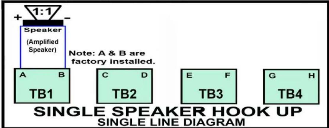
Filename: AMPIC 1 Input Detailed Wiring Diagram 1 SPEAKER 09/12/11
SELF AMPLIFIED SPEAKER TO NON-AMPLIFIED SPEAKERS DETAILED WIRING DIAGRAM
B. TWO SPEAKER COMBINATION WIRING DIAGRAM
Models AMP1S52 & AMP1S62

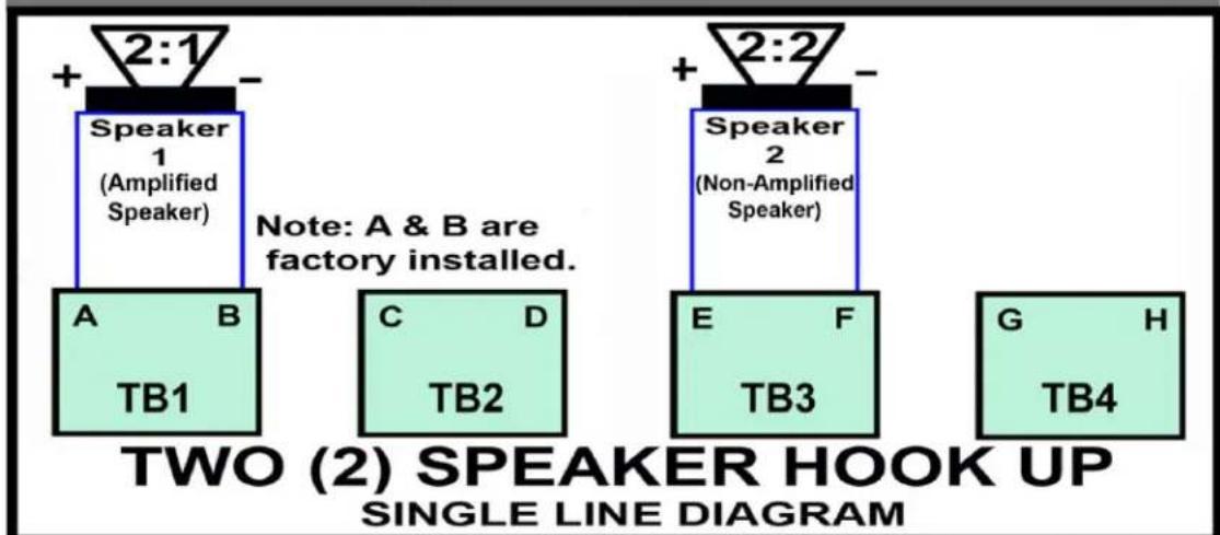
flowchart
graph TD
    A["Speaker 1 (Amplified Speaker)"] --> B["A TB1"]
    C["Speaker 2 (Non-Amplified Speaker)"] --> D["C TB2"]
    E["Speaker 2"] --> F["E TB3"]
    G["Speaker 2"] --> H["G TB4"]
    style A fill:#f9f,stroke:#333
    style C fill:#f9f,stroke:#333
    style E fill:#f9f,stroke:#333
    style G fill:#f9f,stroke:#333
    note right of A: 'Note: A & B are factory installed.'
    note right of C: 'TWO (2) SPEAKER HOOK UP SINGLE LINE DIAGRAM'
File name: AMFIC 1 Input Detailed Wiring Diagram 2 SPEAKERS 09/12/11
SELF AMPLIFIED SPEAKER TO NON-AMPLIFIED SPEAKERS DETAILED WIRING DIAGRAM
C. FOUR SPEAKER COMBINATION WIRING DIAGRAM
Models AMP1S54 & AMP1S64

flowchart
graph TD
    A["SELF-AMPLIFIED SPEAKER TO NON-AMPLIFIED SPEAKER WIRING DIAGRAM"] --> B["Optional Accessories"]
    B --> C["PROYCTOR: LAPTOP, CD, DVD or MP3 PLAYERS"]
    C --> D["Stereo Combiner"]
    C --> E["Volume Control"]
    C --> F["Hum Eliminator"]
    B --> G["Speaker 1 AMPLIFIED SPEAKER (Non-amplified speaker with built-in amplifier)"]
    B --> H["Speaker 2 NON-AMPLIFIED SPEAKER OWI Model IC5 or IC6"]
    B --> I["Speaker 3 NON-AMPLIFIED SPEAKER OWI Model IC5 or IC6"]
    B --> J["Speaker 4 NON-AMPLIFIED SPEAKER OWI Model IC5 or IC6"]
    B --> K["Speaker 1 (Amplified Speaker)"]
    B --> L["Speaker 2 (Non-Amplified Speaker)"]
    B --> M["Speaker 3 (Non-Amplified Speaker)"]
    B --> N["Speaker 4 (Non-Amplified Speaker)"]
    style A fill:#f9f,stroke:#333
    style B fill:#ccf,stroke:#333
Filename: AMPIC 1 Input Detailed Wiring Diagram 4 SPEAKERS 09/12/11
SELF AMPLIFIED SPEAKER TO SELF AMPLIFIED SPEAKER
DETAILED WIRING DIAGRAM
OWI MODEL AMPIC5 / AMPIC6
SELF-AMPLIFIED SPEAKER TO ANOTHER SELF-AMPLIFIED SPEAKER WIRING DIAGRAM

flowchart
graph TD
    A["Switched outlet"] --> B["TOP VIEW OF AMPLIFIER PCB* SIGNAL"]
    B --> C["Output / Input (600 Ohm - 10k Ohm)"]
    C --> D["Self-amplified Speaker"]
    D --> E["Amplifier PCB*"]
    E --> F["Non-Amplified Speakers IC5 or IC6"]
    F --> G["AMPLIFIER PCB*"]
    G --> H["AMPIC5 / AMPIC6 AMPLIFIER LOAD MAXIMUM: 4 OHMS NOMINAL: 8 OHMS"]
    H --> I["Up to 20 self-amplified speakers"]
    I --> J["After conductor is inserted, tighten screw with small flat blade screw driver."]
    J --> K["3-Pin Dockable Connector (Provided) NOTE: Terminate wire conductors to the dockable connector BEFORE plugging into the Amplifier. Recommended speaker wire is 16-18 AWG."]
    style A fill:#f9f,stroke:#333
    style B fill:#ccf,stroke:#333
    style C fill:#cfc,stroke:#333
    style D fill:#fcc,stroke:#333
    style E fill:#cff,stroke:#333
    style F fill:#ffc,stroke:#333
    style G fill:#cfc,stroke:#333
    style H fill:#fcc,stroke:#333
    style I fill:#ffc,stroke:#333
    style J fill:#cfc,stroke:#333
    style K fill:#fcc,stroke:#333
Self Amplified Speaker up to 4 Non-Amplified Speakers

flowchart
graph TD
    A["Internal Speaker w/ Self-Amplified (AMPIC5/6)"] --> B["AMPIC5/6 PC BOARD"]
    C["Non-Amplified (IC5 / IC6)"] --> B
    D["8 Ohms"] --> B
    E["8 Ohms"] --> B
    F["8 Ohms"] --> B
    G["Non-Amplified (IC5 / IC6)"] --> H["WIRING CHART"]
    I["CLASS 2 WIRING"] --> J["TB1 TB2 TB3 TB4"]
    K["SPEAKER HOOK-UP"] --> L["1 SPEAKER = AB\n2 SPEAKERS = AB.EF\n3 SPEAKERS = NA\n4 SPEAKERS = AC, BD, EG, FH"]
    M["Please see chart below for wiring instructions"] --> N["Output Speakers AMPIC5/6 PC BOARD"]
    O["8 Ohms"] --> P["Non-Amplified (IC5 / IC6)"]
    Q["8 Ohms"] --> R["Non-Amplified (IC5 / IC6)"]
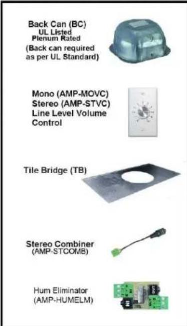
Recommended Accessories
Trouble Shooting Guide
- No output: Disconnect any secondary speakers and check for operation of the primary speaker only. If still there is no output, check for loose screws on the green input connector. It is easy to think the wires are secured in the connector and one wire is not. Tug on each wire to make sure each is tight.
- Intermittent output: Check for a shorted output causing the amplifier to go into output protection. Check each input wire for loose screws.
- Distortion: Do not power more than one AMPIC5/6 on one power supply. While it will work, it will cause distortion.
- No output, check to see that the power on light is on. It is located on the main PCB. If it is off, the power supply is either bad or has come loose in the power socket.
- Hum, for single ended inputs, there is a need for a jumper between - and the ground screw. Most of the time, the jumper is needed.
LIMITED WARRANTY
- The AMPIC5/6 product has been thoroughly tested and inspected at the factory. It is warranted for one (1) year from date of purchase.
IT IS THE OWNERS' RESPONSIBILITY TO ESTABLISH THE DATE OF PURCHASE BY ACCEPTABLE EVIDENCE AT TIME SERVICE IS SOUGHT. - Any unit, which in the judgment of OWI INC. is defective or develops defects under normal use will be replaced or repaired without cost within the warranty period.
- This warranty will be considered void if unit has been dropped, misused, abused and altered in any manner, overdriven with excessive amplification exceeding manufacturer's specification, improperly serviced or accidental damage.
- OWI Inc. shall have no liability whatsoever for consequential damage. The sole responsibility and discretion of OWI Inc. under this warranty shall be limited to the repair of the product or replacement thereof.
- IMPORTANT: This warranty is void unless the attached card is completed and mailed to OWI Inc. within 10 days following the date of purchase. Units must be sent to OWI Inc. or to the dealer where purchased.
OWI INCORPORATED
17141 Kingsview Ave.
Carson, CA 90746-1207 USA
Date Purchased: ____
Model Number: ____
Serial Number: ____
(Keep this part for your record)
----CUT AND MAIL----

OWI INCORPORATED
17141 Kingsview Ave
Carson, CA 90746-1207 USA
LIMITED WARRANTY
(Self-Amplified Speaker - 1 year) – AMPIC5 / AMPIC6
(Non-Amplified Speaker - 5 years) - IC5 / IC6
Model Number: ____
Model Name: ____
Serial No.
Date of Purchase: Month: ____ Day ____ Year ____
Owner's Name: ____
Address: ____
City: ____ State ____ Zip ____
Dealer's Name: ____ City ____ State ____
Purchased from (please check one):
Video __, Electronic __, Mail Order __, Mass Merchandiser __, Installer __
Others (please specify) ____
Remarks:
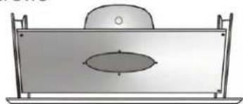
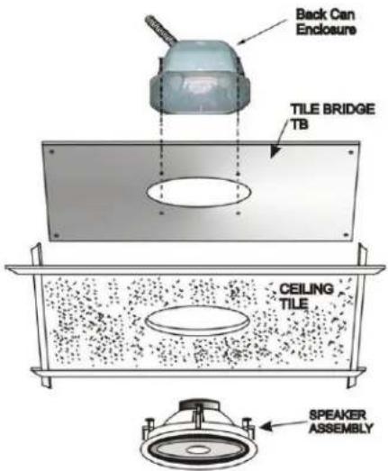
The Quick and Easy Way to Install the OWI TB (Tile Bridge) and the
Backcan Enclosure with a 6-1/2" or 5-1/4" OWI In-Ceiling Speaker.
- Position the enclosure over the speaker hole and align it with the screw holes in the tile bridge. Insert and tighten 4 screws through the enclosure into the holes on top of the tile bridge.

- Insert and tighten four screws to attach the tile bridge to the beam.
natural_image
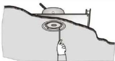
Simple line drawing of a rectangular container with an oval opening, mounted on a stand (no text or symbols)- After hole is cut in the ceiling, connect the wires and install the speaker by tightening the screws of the four clamps.
natural_image
Illustration of a hand holding a circular object above a sloped surface, with no visible text or symbols.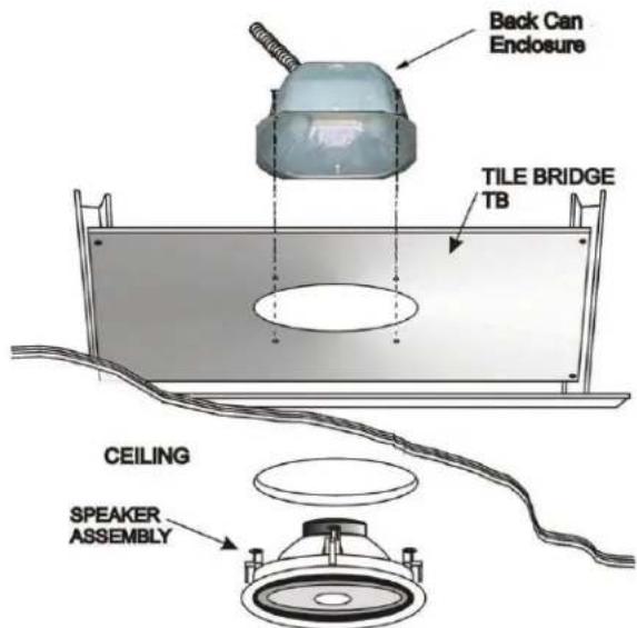

OWI INCORPORATED
17141 Kingsview Avenue, Carson, CA 90746-1207 USA
Tel: 310.515.1900 Fax: 310.515.1606
Email: info@owi-inc.com Website: www.owi-inc.com

The Quick and Easy Way to Install the OWI TB (Tile Bridge) and the Backcan Enclosure with a 6-1/2" or 5-1/4" OWI In-Ceiling Speaker.
The TB will work on a 2' X 4', 2' X 2' lay-in type ceilings.
| 1. Use one tile bridge (TB) as a template to make cut outs for all the ceiling tiles. |  | 5. Remove the templa saw out the circle (hole). Set ceiling t aside. |  |
| 2. To save time, cut 2 ceiling tiles at the same time.Lay the ceiling tile face to face. |  | 6. Place one ceiling tile face down on the floor or on top of a table. Position the TB tile bridge across the tile with the speaker holes coinciding with each other. |  |
| 3. After finding the center of the ceiling tile, position the tile bridge template across the tile. | 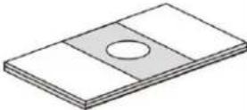 | 7. Position the enclosure over the hole and align it with the scre in the tile bridge. Insert and tighten 4 screws through the enclosure into the holes on top of the tile bridge through the ceiling tile. | 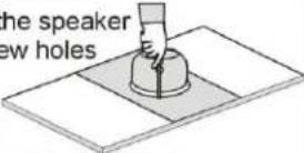 |
| 4. Draw a circle using the speaker hole of the template (tile bridge). |  | 8. After connecting the speal the speaker assembly thr the hole and tighten the screws of the 4 clamps. The 4 clamps will hold the and the ceiling tile together |  |
TEE BAR CEILING ASSEMBLY
IN-CEILING/WALL-MOUNT SPEAKERS INSTALLATION/OWNERS' MANUAL
MODEL IC5 / IC6 (NON-AMPLIFIED SPEAKERS)
SPEAKER SPECIFICATIONS:
| MODEL IC5 | MODEL IC6 | |
| DESCRIPTION: | 5.25" 2-way in-ceiling speaker | 6.5" 2-way in-ceiling speaker |
| COVERED OUTDOOR: | Yes | Yes |
| IMPEDANCE: | 8 ohms | 8 ohms |
| SENSITIVITY (1W/1M): | 86dB 1w/M | 87dB 1w/M |
| DISPERSION: | 140^ | 140^ |
| MAX POWER: | 40 watts | 50 watts |
| NOMINAL POWER: | 20 watts | 25 watts |
| FREQUENCY RESPONSE: | 90Hz - 20KHz | 65Hz-20KHz |
| WOOFER SIZE: | 5.25" | 6.5" |
| WOOFER MATERIAL: | Paper coated woofer with foam surround | Paper coated woofer with foam surround |
| TWEETER SIZE: | 0.5" (13mm) balance tweeter | 0.5" (13mm) balance tweeter |
| TWEETER MATERIAL: | Ferrite magnet with Mylar diaphragm material | Ferrite magnet with Mylar diaphragm material |
| GRILL MATERIAL: | Aluminum | Aluminum |
| DIMENSIONS: | 7.95” (202mm) Dia. x 2^3/4 ” (70mm) mounting depth | 8 ^3/4 ” (223mm) Dia. x 3^3/8 ” (85mm) mounting depth |
| CUT OUT SIZE: | 6 ^5/8 ,” (168mm) | 7 ^11/16 ,” (195mm) |
| WEIGHT: | 2.17 lbs (985 gms) | 2.51 lbs. (1140 gms) |
| MOUNTING HARDWARE: | Clamps - 4 each | Clamps - 4 each |
| PAINTABLE: | Yes | Yes |
INSTALLATION:
Speaker Placement
Before installing your OWI speakers, consider the placement carefully, taking into effect the location of electrical, plumbing and other fixtures.
Placement in Ceiling
OWI speakers should be ideally located above the primary listening area.
Placement in Wall
Optimum sound will be achieved when your OWI speakers are installed at ear level or slightly higher and the listening area is no closer to the speakers than the distance between the speakers themselves.
Mounting your OWI Speakers
Determine the best area to mount your OWI speakers. It will be necessary to run your speaker wires to that location. This location must be free of obstructions, such as electrical conduits, HVAC ducts, or water lines.
Be sure the mounting surface is between 3/8 and 1 1/4 inches thick and there is at least a 2 3/4 inch clearance behind the mounting surface and no wall studs or other objects block the back of the speaker.
Remove the round cardboard disc from the template supplied and keep it for later use as a paint mask, if you decide to paint your speakers.
Use the template to mark the position for the mounting hole at the selected location. If you are not certain that no obstruction exists (electrical wiring, plumbing, etc.), you should start by cutting a small hole in the center of your penciled mounting hole with a drywall or keyhole saw, cutting at a 45 degree angle towards the inside of the hole. Cutting a small hole at this angle will make drywall repair much easier. Once you have determined there are no obstructions in your desired mounting location, start cutting the finished hole at a 90 degree angle to the wall/ceiling surface.
Route the speaker wires from your amplifier to your opening. Avoid routing the speaker wire near electrical wires. If you have to run them parallel, make certain to space the speaker wires at least 2 feet from the AC line. Do not nail or staple the speaker wire.
Preparing your OWI Speakers for Mounting
Insert a paper clip into one of the grille openings, then pull upwards to remove the grille.
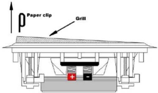
Be sure to position the four Mounting Tabs on your OWI speaker inward then insert the four screws (supplied) from the front of the speaker into the screw opening.
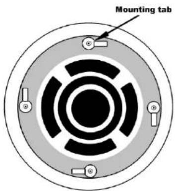
Attach the speaker wires to the speaker terminals.
Insert your OWI speaker into the opening and tighten the four screws. As you tighten the screws, the tabs will automatically flip into an outward position thereby clamping the drywall between the feet and the flange of the speaker. BE CAREFUL NOT TO OVER TIGHTEN, OVER TIGHTENING MAY WARP THE BAFFLE, CRACK THE WALL, CAUSE THE FLANGE TO DISTORT AND MAKE THE GRILL DIFFICULT TO INSTALL.
Push the grille firmly into the slot in the speaker baffle.
Painting your OWI Speakers
The speakers' other surfaces are primed to accept ordinary latex wall paint or aerosol spray paint. The surface of the speaker behind the grille should remain black and must not be painted. It is necessary to mask this area with the center of the template that you have cut out.
The grille can be painted as well, but great care must be taken not to clog the holes in the grille as this will greatly reduce the sound quality of the speakers. It is recommended that only light spray painting using 5 parts thinning agent to 1 part paint be used. Do not paint the grilles while they are attached to the speaker.
Proper Wire Gauge Selection
The gauge of wire required is determined by the distance between your amplifier/receiver and the speakers. Use the following chart as a guide:
| Length | Minimum Gauge |
| Less than 10 feet | 18 - 20 Gauge |
| 10 to 100 feet | 16 to 18 Gauge |
| Over 100 feet | 14 Gauge |

OWI INC.
LIMITED FIVE YEAR WARRANTY
(IC5/IC6 NON-AMPLIFIED IN-CEILING SPEAKER)
-
Your OWI speakers have been thoroughly tested and inspected at the factory. They are warranted for 5 years from the date of purchase. It is the owner's responsibility to establish the date of purchase by acceptable evidence at the time service is sought.
-
If the speaker proves to be defective in materials or workmanship within five years from the date of the original customer purchase, OWI, at its sole option may repair or replace the unit with a current model of equal or greater value. In some cases where a new model is substituted, a modification to the mounting surface may be required. If mounting surface modification is required, OWI assumes no responsibility or liability for such modification.
-
Exclusion of certain damages
Liability for any defective product is limited to repair or replacement of the product at our option. OWI Inc. shall have no liability whatsoever for any incidental or consequential damages of any kind of character because of product defect. The sole responsibility of OWI Inc. under this warranty shall be limited to the repair of the product or replacement thereof, and is the sole discretion of OWI Inc. Some states do not allow limitation on how long an implied warranty lasts and/or do not allow the exclusion or limitation of incidental or consequential damages, so the above limitation may not apply.
- This warranty does not cover:
a. Damage caused by abuse, accident, misuse, negligence, improper operation (installation), overdriven with excessive amplification.
b. Products that have been altered or modified.
c. Any product whose serial number has been altered or removed.
d. Normal wear and maintenance.
e. Damages caused by shipping. All claims for shipping must be made with the carrier.
- What OWI Inc. will pay for and what YOU must pay for:
OWI will repair or replace unit(s) covered by this warranty without charge to the customer for labor or materials. You are responsible for any installation or removal charges and for any initial shipping charges, if the unit(s) must be shipped for warranty service. However, OWI Inc. will pay the return shipping charges to any destination within the USA, if the repairs are covered by the warranty.
- Warranty Service
Units for warranty repair must be sent to OWI Inc., or to the dealer where purchased, postage prepaid. Copy of original proof of purchase to be included with the speaker(s).
| OWI SELF-AMPLIFIED SINGLE SOURCE/INPUT IN-CEILING SPEAKER COMBINATION PROGRAM | ||||||||
| 5" MODEL | AMPIC5(Single Input)(UL Listed) | POWER SUPPLY(UL Rated) | ICS(8 ohms)(UL Listed) | TILE BRIDGE STB(UL Listed) | BACKCAN(UL Listed)Pleasm Rated | OLUME CONTROSTEREOAMPSTVOW | STEREOCOMBINERAMP-STCOMB | |
| MODEL NAME(SKU |  |  |  |  |  |  |  | |
| A ONE SPEAKER | ||||||||
| A1 AMP1S51 | 1ea. | 1ea. | - | 1ea. | 1ea. | - | Optional | |
| A2 AMP1S51SVC | 1ea. | 1ea. | - | 1ea. | 1ea. | 1ea. | (Sold Separately) | |
| B TWO SPEAKERS | ||||||||
| B1 AMP1S52 | 1ea. | 1ea. | 1ea. | 2ea. | 2ea. | - | Optional | |
| B2 AMP1S52SVC | 1ea. | 1ea. | 1ea. | 2ea. | 2ea. | 1ea. | (Sold Separately) | |
| C FOUR SPEAKERS | ||||||||
| C1 AMP1S54 | 1ea. | 1ea. | 3ea. | 4ea. | 4ea. | - | Optional | |
| C2 AMP1S54SVC | 1ea. | 1ea. | 3ea. | 4ea. | 4ea. | 1ea. | (Sold Separately) | |
| 6" MODEL | AMPIC6(Single Input)(UL Listed) | POWER SUPPLY(UL Rated) | IC6(8 ohms)(UL Listed) | TILE BRIDGE 6TB(UL Listed) | BACKCAN(UL Listed)Pleasm Rated | OLUME CONTROSTEREOAMPSTVOW | STEREOCOMBINERAMP-STCOMB | |
| MODEL NAME(SKU | Available in While (N) | |||||||
| D ONE SPEAKER | ||||||||
| D1 AMP1S61 | 1ea. | 1ea. | - | 1ea. | 1ea. | - | Optional | |
| D2 AMP1S61SVC | 1ea. | 1ea. | - | 1ea. | 1ea. | 1ea. | (Sold Separately) | |
| E TWO SPEAKERS | ||||||||
| E1 AMP1S62 | 1ea. | 1ea. | 1ea. | 2ea. | 2ea. | - | Optional | |
| E2 AMP1S62SVC | 1ea. | 1ea. | 1ea. | 2ea. | 2ea. | 1ea. | (Sold Separately) | |
| F FOUR SPEAKERS | ||||||||
| F1 AMP1S64 | 1ea. | 1ea. | 3ea. | 4ea. | 4ea. | - | Optional | |
| F2 AMP1S64SVC | 1ea. | 1ea. | 3ea. | 4ea. | 4ea. | 1ea. | (Sold Separately) | |
Please visit www.owi-inc.com for more of OWI's wide array of Quality Audio Products.
OWI INCORPORATED
17141 KINGSVIEW AVE. CARSON, CA 90746-1207 USA
TEL: 310-515-1900 * FAX: 310-515-1606
info@owi-inc.com
www.owi-inc.com

- Installation Instructions
- Models AMPIC5 / AMPIC6
- CAUTION RISK OF ELECTRIC SHOCK
- CAUTION: TO REDUCE THE RISK OF ELECTRIC SHOCK DO NOT REMOVE COVER (OR BACK) NO USER-SERVICEABLE PARTS INSIDE REFER SERVICING TO QUALIFIED PERSONNEL
- IMPORTANT SAFETY INSTRUCTIONS
- AMP1S51, AMP1S52, AMP1S54, AMP1S61, AMP1S62 & AMP1S64
- Introduction:
- Specifications:
- Model Number
- AMPIC5 / AMPIC6
- OWI SELF-AMPLIFIED (SINGLE INPUT/ SOURCE) SPEAKER MODULE
- Description:
- Lower Noise Feature, Differential input
- Single ended sources (unbalanced) such as CD, DVD
- Minimum additional space
- Wiring to down stream power modules using the provided output connector
- Power source
- Wire gauge
- Low level audio wire runs
- Powering secondary speakers without amplifiers in paging only applications
- Amplifier Protection
- Loud music installations, dance floors etc.
- SELF AMPLIFIED SINGLE SPEAKER
- DETAILED WIRING DIAGRAM
- ONE AMPLIFIED SPEAKER WIRING DIAGRAM
- SELF AMPLIFIED SPEAKER TO NON-AMPLIFIED SPEAKERS DETAILED WIRING DIAGRAM
- FOUR SPEAKER COMBINATION WIRING DIAGRAM
- SELF AMPLIFIED SPEAKER TO SELF AMPLIFIED SPEAKER
- OWI MODEL AMPIC5 / AMPIC6
- Trouble Shooting Guide
- LIMITED WARRANTY
- The Quick and Easy Way to Install the OWI TB (Tile Bridge) and the
- Backcan Enclosure with a 6-1/2" or 5-1/4" OWI In-Ceiling Speaker.
- OWI INCORPORATED
- The Quick and Easy Way to Install the OWI TB (Tile Bridge) and the Backcan Enclosure with a 6-1/2" or 5-1/4" OWI In-Ceiling Speaker.
- The TB will work on a 2' X 4', 2' X 2' lay-in type ceilings.
- IN-CEILING/WALL-MOUNT SPEAKERS INSTALLATION/OWNERS' MANUAL
- MODEL IC5 / IC6 (NON-AMPLIFIED SPEAKERS)
- INSTALLATION:
- Speaker Placement
- Placement in Ceiling
- Placement in Wall
- Mounting your OWI Speakers
- Preparing your OWI Speakers for Mounting
- Painting your OWI Speakers
- Proper Wire Gauge Selection
- OWI INC.
- LIMITED FIVE YEAR WARRANTY
- (IC5/IC6 NON-AMPLIFIED IN-CEILING SPEAKER)
Brand : OWI
Model : AMPIC5
Category : Loudspeaker