AHS627-23 - Smart Home ALC - Free user manual and instructions
Find the device manual for free AHS627-23 ALC in PDF.

| Product Type | Smart Home Hub |
| Brand | ALC |
| Model | AHS627-23 |
| Dimensions (W x H x D) | 120 x 80 x 30 mm |
| Weight | 200 g |
| Power Supply | 5V DC, 1A via USB |
| Power Consumption | 5 W max |
| Connectivity | Wi-Fi 2.4 GHz, Bluetooth 4.2 |
| Compatible Systems | Amazon Alexa, Google Home |
| Voice Control | Yes |
| Smart Home Protocols | Zigbee, Z-Wave (optional) |
| Number of Supported Devices | Up to 50 |
| Automation Rules | Unlimited (via app) |
| Operating Temperature | 0°C to 40°C |
| Operating Humidity | 10% to 90% non-condensing |
| Maintenance | Wipe with a soft, dry cloth |
| Safety Certifications | CE, FCC, RoHS |
| Spare Parts Availability | Not applicable (integrated unit) |
| Repairability Index | 4/10 (non-user serviceable) |
| General Information | Smart home hub with voice control and automation |
Frequently Asked Questions - AHS627-23 ALC
User questions about AHS627-23 ALC
0 question about this device. Answer the ones you know or ask your own.
Ask a new question about this device
Download the instructions for your Smart Home in PDF format for free! Find your manual AHS627-23 - ALC and take your electronic device back in hand. On this page are published all the documents necessary for the use of your device. AHS627-23 by ALC.
USER MANUAL AHS627-23 ALC
Wireless Security System
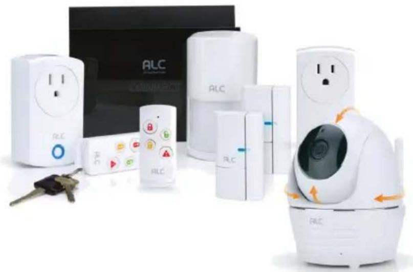
natural_image
Product display of white RLC home security devices including lockers, controllers, and a smart home with control buttons (no visible text or symbols)Models: AHS627-23
User Guide
Please read these instructions completely before operating this product.
IMPORTANT MODEL NUMBER INFORMATION
This manual covers separate devices. This manual may contain information on a device that is not included for your system but can be purchased separately by visiting:
ALCWireless.com
See page 6 for information on what is included with your system.
IMPORTANT SAFETY INSTRUCTIONS ....3
INTRODUCTION....6
System Contents....6
Getting to Know Your Security System 7
Getting to Know Your Camera....8
Cloud....8
GETTING STARTED 9
Downloading the App 9
Pairing the Sensors....9
Connecting to the Control Hub 10
Pairing the Camera - Android....13
Pairing the Camera - IOS....15
INSTALLATION....17
Installation Tips....18
Night Vision 18
Installing the Camera 19
Installing the Door/Window Sensor 21
Installing the Motion Detector....22
ALC CONNECT APP STATUS SCREEN 23
Basic Operation....23
REMOTE ACCESS 29
Camera Screen....29
Live Video Screen 30
Recording from the Status Screen 33
To Play Videos....34
To Delete Recordings ....37
ALC CONNECT APP SCENARIO SCREEN 38
Remote Control Function....38
Scenario 39
Shortcut 40
CLOUD 41
Cloud Account Setup 41
PAIRING 45
Pairing the Door/Window Sensor 45
Pairing the Motion Detector 46
Pairing the Power Switch....47
Pairing the Remote Control....48
Connecting to Nest....49
TROUBLESHOOTING 50
Factory Default/Reset 51
PRODUCT SPECIFICATIONS....52
Control Hub/Siren....52
Camera 52
Remote Control 52
Motion Detector....53
Power Switch 53
Door/Window Sensor 53
WARRANTY 54
PRODUCT SAFETY: When used in the directed manner, this unit has been designed and manufactured to ensure your personal safety. Improper use of this product can result in potential electrical shock or fire hazards. Please read all safety and operating instructions carefully before installation and use, and keep these instructions handy for future reference.
CAUTION
RISK OF ELECTRIC SHOCK DO NOT OPEN
CAUTION: To reduce the risk of electric shock do not remove cover (or back). No user serviceable parts inside. Refer servicing to qualified service personnel.
DANGEROUS VOLTAGE: The lightning flash with arrowhead, within an equilateral triangle, is intended to alert the user to the presence of uninsulated dangerous voltage within the product's enclosure that may be of sufficient magnitude to constitute a risk of electric shock to persons.

ATTENTION: The exclamation point within an equilateral triangle is intended to alert the user to the presence of important operating and maintenance (servicing) instructions in the literature accompanying the appliance.
WARNING: TO PREVENT FIRE OR SHOCK HAZARD, DO NOT EXPOSE THIS UNIT TO RAIN OR MOISTURE.

Products with CE Marking comply with EMC Directive (2004/108/EC); Low Voltage Directive (73/23/EEC); R&TTE(1999/5/EC); ROHS Directive (2011/65/EU) issued by the Commission of the European Community. Compliance with these directives implies conformity to the following European Norms:
EMC: EN 301 489 LVD: EN 60950 Radio: EN 300 328

FCC Compliance Statement: This device complies with Part 15 of the FCC rules. Operation is subjected to the following two conditions: (1) this device may not cause harmful interference, and (2) this device must accept any interference received, including interference that may cause undesired operation.
FCC/CE WARNING
This equipment has been tested and found to comply with limits for a Class B digital device, pursuant to Part 15 of the FCC rules and ETSI(EN) 300328. These limits are designed to provide reasonable protection against harmful interference in residential installations. This equipment generates, uses, and can radiate radio frequency energy, and if not installed and used in accordance with the instructions, may cause harmful interference to radio communications. However, there is no guarantee that interference will not occur in a particular installation. If this equipment does cause interference to radio or television equipment reception, which can be determined by turning the equipment off and on, the user is encouraged to try to correct the interference by one or more of the following measures:
- Reorient or relocate the receiving Antenna.
- Move the equipment away from the Monitor.
- Plug the equipment into an outlet on a circuit different from that to which the Monitor is connected.
- Consult the dealer or an experienced radio/television technician for additional suggestions.
CAUTION: Any changes or modifications to this equipment not expressly approved by the party responsible for compliance could void your authority to operate the equipment.
Recycling and Disposal Information:
- Do not dispose of electronic devices or any of their components (especially batteries and LCD displays) in your municipal trash collection.
- Consult your local waste management authority or a recycling organization like Earth911.com to find an electronics recycling facility in your area.
CAUTION: Rechargeable batteries must be recycled or disposed of properly.
WARNING:
STRANGULATION HAZARD: Infants have STRANGLED in power cords. Keep power cords more than three feet away from cribs, bassinets, play yards, and other safe sleep environments for infants.
IMPORTANT SERVICE SAFETY INSTRUCTIONS
Damages caused by non-compliance with this operating manual will void the warranty!
- Read and Follow Instructions - All the safety and operating instructions should be read before the product is operated. Follow all operating instructions.
- Retain Instructions - The safety and operating instructions should be retained for future reference.
- Heed Warnings - Comply with all warnings on the product and in the operating instructions.
- Power Sources - This product should be operated only from the type of power source indicated on the marking label. If you are not sure of the type of power supplied to your location, consult your video dealer or local power company. For products intended to operate from battery power, or other sources, refer to the operating instructions.
- Overloading - Do not overload wall outlets or extension cords as this can result in the risk of fire or electric shock. Overloaded AC outlets, extension cords, frayed power cords, damaged or cracked wire insulation, and broken plugs are dangerous. They may result in a shock or fire hazard. Periodically examine the cord, and if its appearance indicates damage or deteriorated insulation, have it replaced by your service technician.
- Power-Cord Protection - Power supply cords should be routed so that they are not likely to be walked on or pinched by items placed upon or against them. Pay particular attention to cords at plugs, convenience receptacles, and the point where they exit from the product.
- Surge Protectors - It is highly recommended that the video equipment be connected to a surge protector. Doing so will protect the equipment from damage caused by power surges. Surge protectors should bear the UL listing mark or CSA certification mark.
- Uninterruptible Power Supplies (UPS) - Because this product is designed for continuous, 24/7 operation, it is recommended that you connect the product to an uninterruptible power supply. An uninterruptible power supply has an internal battery that will keep the product running in the event of a power outage. Uninterruptible power supplies should bear the UL listing mark or CSA certification mark.
CAUTION: Maintain electrical safety. Power line operated equipment or accessories connected to this product should bear the UL listing mark or CSA certification mark on the accessory itself and should not be modified so as to defeat the safety features. This will help avoid any potential hazard from electrical shock or fire. If in doubt, contact qualified service personnel.
- Ventilation - Slots and openings in the case are provided for ventilation to ensure reliable operation of the product and to protect it from overheating. These openings must not be blocked or covered. The openings should never be blocked by placing the video equipment on a bed, sofa, rug, or other similar surface. This product should never be placed near or over a radiator or heat register. This product should not be placed in a built-in installation such as a bookcase or rack unless proper ventilation is provided and the product manufacturer's instructions have been followed.
- Attachments - Do not use attachments unless recommended by the product manufacturer as they may cause a hazard.
- Water and Moisture - Do not use receivers or video monitors near water — for example, near a bath tub, wash bowl, kitchen sink or laundry tub, in a wet basement, near a swimming pool and the like.
- Heat - The product should be situated away from heat sources such as radiators, heat registers, stoves, or other products (including amplifiers) that produce heat.
- Accessories - Do not place this video equipment on an unstable cart, stand, tripod, or table. The video equipment may fall, causing serious damage to the product. Use this product only with a cart, stand, tripod, bracket, or table recommended by the manufacturer or sold with the product. Any mounting of the product should follow the manufacturer's instructions and use a mounting accessory recommended by the manufacturer.
- Camera Extension Cables - Check the rating of your extension cable(s) to verify compliance with your local authority regulations prior to installation.
- Mounting - The cameras provided with this system should be mounted only as instructed in this guide or the instructions that came with your cameras, using the provided mounting brackets.
- Camera Installation - Cameras are not intended for submersion in water. Not all cameras can be installed outdoors. Check your camera's environmental rating to confirm if it can be installed outdoors. When installing cameras outdoors, installation in a sheltered area is recommended.
BATTERY PRECAUTIONS
Follow these precautions when using batteries in this device:
- Warning – Danger of explosion if battery is incorrectly replaced. Replace only with the same or equivalent type.
- Use only the size and type of batteries specified.
- Be sure to follow the correct polarity when installing the batteries as indicated in the battery compartment. A reversed battery may cause damage to the device.
- Do not mix different types of batteries together (e.g. Alkaline, Rechargeable and Carbon-zinc) or old batteries with fresh ones.
- If the device is not to be used for a long period of time, remove the batteries to prevent damage or injury from possible battery leakage.
- Do not try to recharge a battery not intended to be recharged; it can overheat and rupture. (Follow battery manufacturer's directions.)
- Remove batteries promptly if consumed.
- Clean the battery contacts and also those of the device prior to battery installation.
System Contents
After unpacking, you will have the following items:
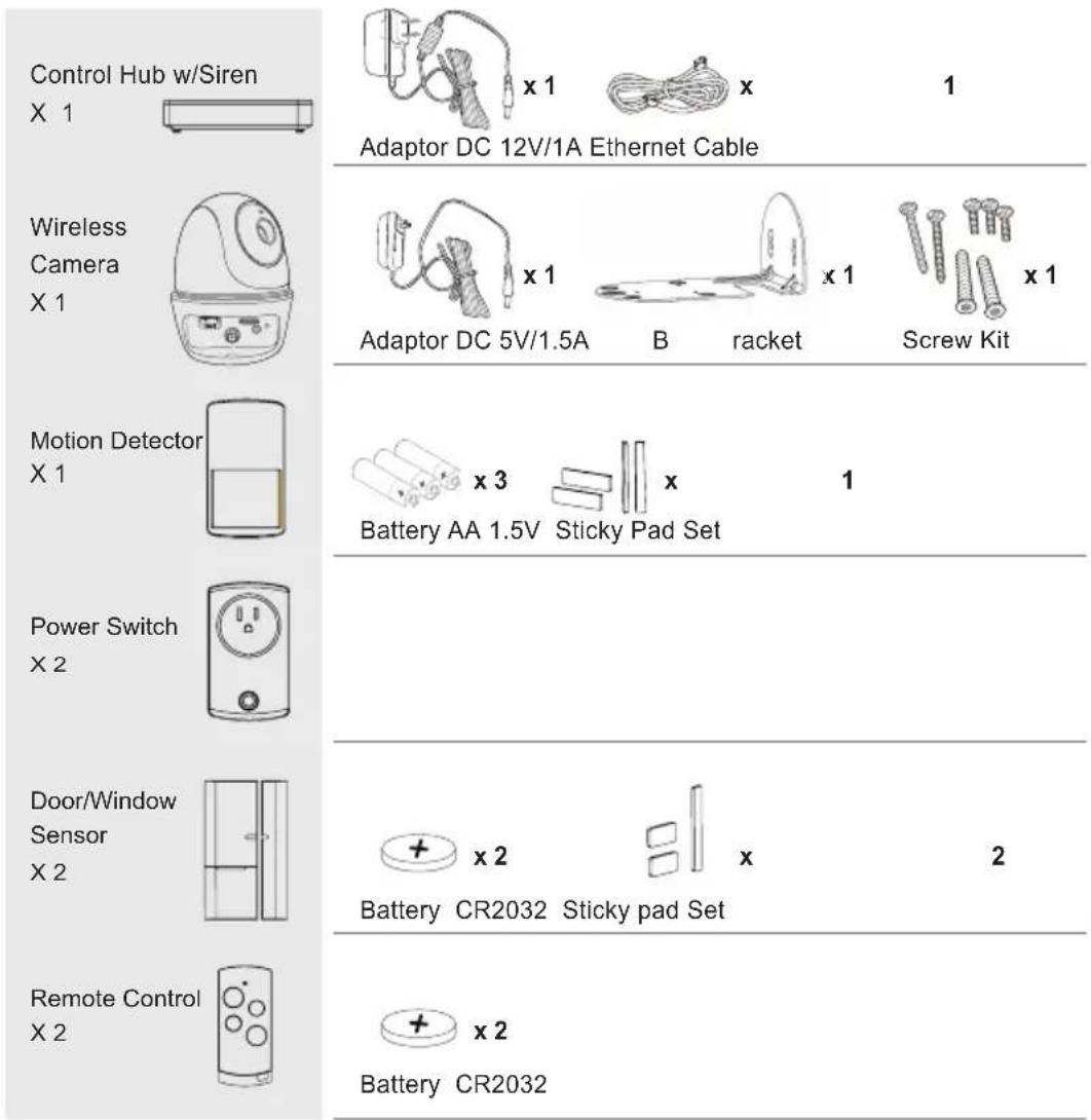
Also included but not pictured:
16GB SD card
2x Warning Stickers
Getting to Know Your Security System
The AHS627-23 is an upgradeable security system that comes with everything you need to start protecting your home. You can increase security at any time by adding additional sensors and/or cameras. The system is easily accessed anywhere in the world via Internet. The free iOS/Android App allows you to view/record video, turn power switch(es) on/off, activate/deactivate the siren manually or automatically. Please read the manual fully to understand all the features the system and App contain.
See below for explanation of each device:
Control Hub w/Siren
X 1

Wireless
Camera
X1
Motion Detector
X1
Power Switch
X2
Door/Window
Sensor
X2
Remote Control
X2
The central control of the Secure Home Connect system provides communication for remote access, sensors and mobile devices. The Control Hub can send out push notifications and Emails when a sensor is triggered. Also included a built-in Siren that can be controlled via the App and Panic button on the remote control or triggered by other devices such as Camera, Door/Window Sensor and Motion Detector.
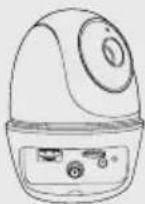
The 1080p Pan & Tilt Wireless Camera will supply day and night viewing thanks to the built-in night vision. Using the free Android or iOS App, you can view live at any time, and set it up to record when an event is triggered (i.e. window sensor, etc.).
The Motion Detector (PIR) is built for larger area detection, such as a living room or entrance. Once motion is detected, the Motion Detector can alert the system and activate the Power Switch (turning on light), Siren (alert sound) and Camera (view/record), if set.
Note: To conserve battery power, the Motion Detector will be temporarily deactivated for two minutes after every trigger event.
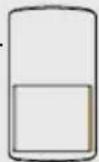
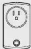
The Power Switch can be set to turn on after a Door/Window Sensor or PIR is triggered) or Panic button is pressed on the Remote Control.
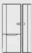
The Door/Window Sensor is installed on a door or window and when triggered (separated), it can activate the Power Switch (to turn on a light, etc.), activate the siren, etc. depending on the App settings.
Use the Remote Control to ARM/DISARM the system or set off Siren. You can preset the buttons to operate various sequences of events with the paired devices.
Getting to Know Your Camera
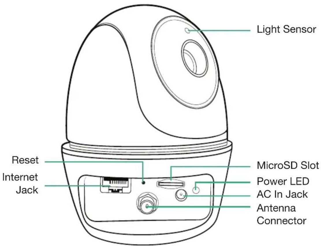
Cloud
When a MicroSD card is inserted and the Cloud option is activated (see page 27), recorded videos will automatically be transferred onto the cloud. To set up a Cloud Account see page 41.
Downloading the App

Download the ALC Connect Plus App as follows:
APPLE DEVICE:
From your iPhone or iPad, go to the App Store and search for ALC Connect Plus.

ANDROID DEVICE:
From your Android smartphone or tablet device, go to Google Play and search for ALC Connect Plus.

natural_image
Blue house icon with 'ALC' text and wireless signal symbol (no additional text or labels)

TO CONNECT VIA DIRECT CONNECT: HUB MUST
BE CONNECTED VIA THE ETHERNET CABLE. Connect one end of the supplied Internet cable into the back of the hub and the other end to your primary router (from your internet service provider).
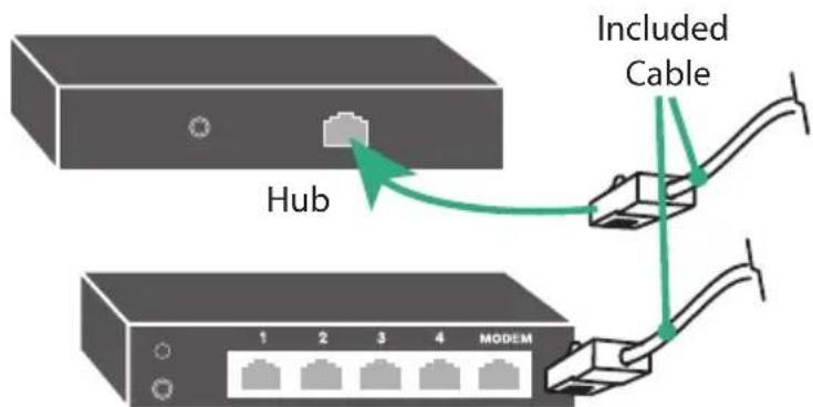
Internet Router (not included)
Pairing the Sensors
The sensors included with the system have already been paired to the control hub prior to leaving the factory. Pairing is not necessary. If additional sensors are purchased, they must be paired to the control hub in order to work. See page 45 for pairing new sensors.
Connecting to the Control Hub
1
Connect the Control Hub to the router as shown on the previous page.
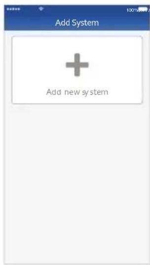
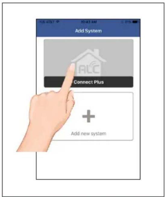
Launch the previously installed ALC Connect Plus App.

natural_image
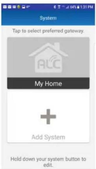
Blue house icon with 'ALC' and wireless signal symbol (no text or numbers)3
Tap Add new system.
2
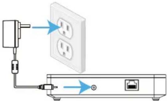
Connect one end of the AC Adaptor to the DC IN jack on the rear of the Control Hub and the other end to a 120 volt AC (standard indoor) power outlet; the Red Power indicator will light and the unit will beep twice. After \~25 seconds, it will beep twice again to indicate that the Control Hub is ready to set up.
natural_image
Diagram showing connection between a power outlet, switch, and network device (no text or symbols)4
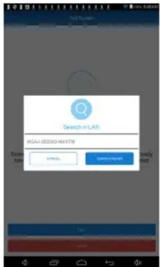
The app will search for the Control Hub and retrieve the Control Hub DID automatically. Tap it to continue the setup. If it does not detect it, tap Search Again. If still unsuccessful, tap Cancel, tap Next and scan in the barcode located on the device. Follow the instructions on the screens.
Connecting to Control Hub
5
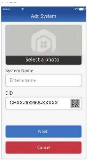
Name the system (i.e. "Home System") and add a photo (if desired). Tap Next.
6
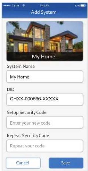
Enter a Security Code (must be 6 characters or more, letters and/or numbers). Repeat and then tap Save.
7
Select your gateway.
8
The Home page (Status page) will display.
Connecting to Control Hub

The included sensors have already been paired to your Hub. Now we will need to name and provide a location for each.

Tap on each sensor to edit the name and location for each. Such as Door Sensor, Front Door or Power Switch, Hall Lamp.

Remove the plastic tabs on the Door, Motion and Remote sensors. Now the sensors can be placed in position.
Pairing the Camera - Android
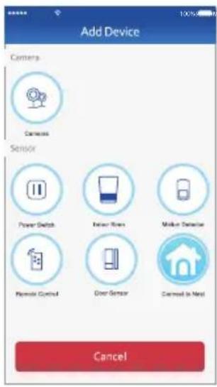
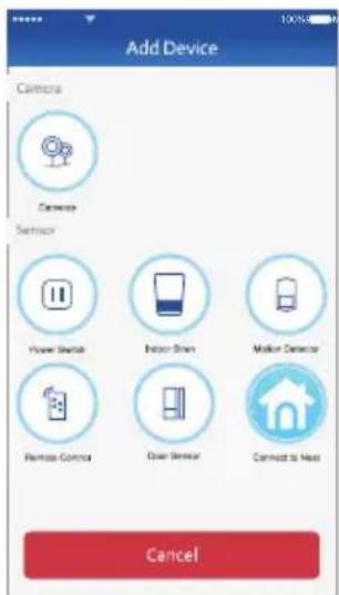
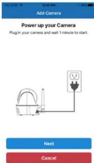
1 At the dashboard, tap “+” (Add Device). Tap Cameras from the Device list.
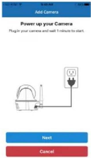
2 Plug camera into an electrical outlet and the camera will boot up. The process can take up to 90 seconds. When the green Link Status indicator begins blinking, the camera is ready to be set up. Tap Next.
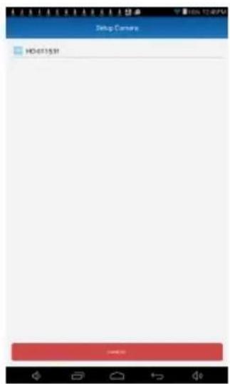
3 The app will search for your camera. The search will locate the camera and retrieve the DID automatically. Tap it and continue the setup
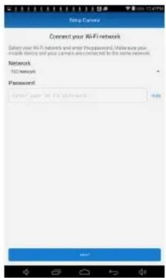
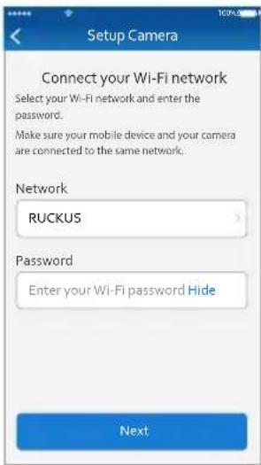
4 Select your Wi-Fi network. Enter the network's password and then tap Next.
Pairing the Camera - Android
5
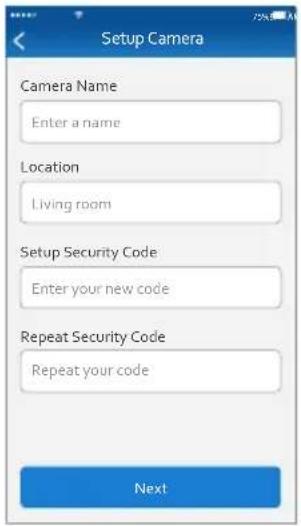
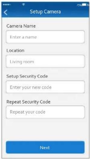
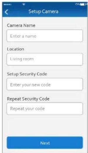
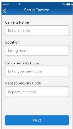
The camera will reboot and connect to your Wi-Fi. This will take approximately 90 seconds. Name the camera and the location of the camera.
6
Enter a new Security Code (must be 6 characters or more, letters and/or numbers). Repeat and then tap Next. The unit will prepare your camera and then it will be paired.
7
The camera icon should now be added. Tap on it to go to Live video.
Pairing the Camera - iOS
1 At the dashboard, tap “+” (Add Device). Tap Cameras from the Device list.
2 Plug camera into an electrical outlet and the camera will boot up. The process can take up to 90 seconds. When the green Link Status indicator begins blinking, the camera is ready to be set up. Tap Next.
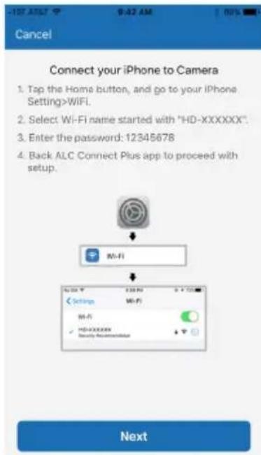
3 For iOS devices, follow the instructions on the screen:
a. Tap on the IOS Device's Home button.
b. Go to Settings, then Wi-Fi.
c. Select the Wi-Fi network called "HD-xxxxxx".
d. Enter the password 12345678, then Join.
e. After it connects (check-mark will appear next to the HD-xxxxxx), go back and to the ALC Connect Plus app.
Pairing the Camera - iOS
4
After restarting the ALC Connect Plus app, the phone will connect to the camera.
Select your Wi-Fi network. Enter the network's password and then tap Next.
5
Name the camera and the location of the camera.
6
Enter a new Security Code (must be 6 characters or more, letters and/or numbers). Repeat and then tap Next. The unit will prepare your camera and then it will be paired.
7
The camera icon should now be added. Tap on it to go to Live video.
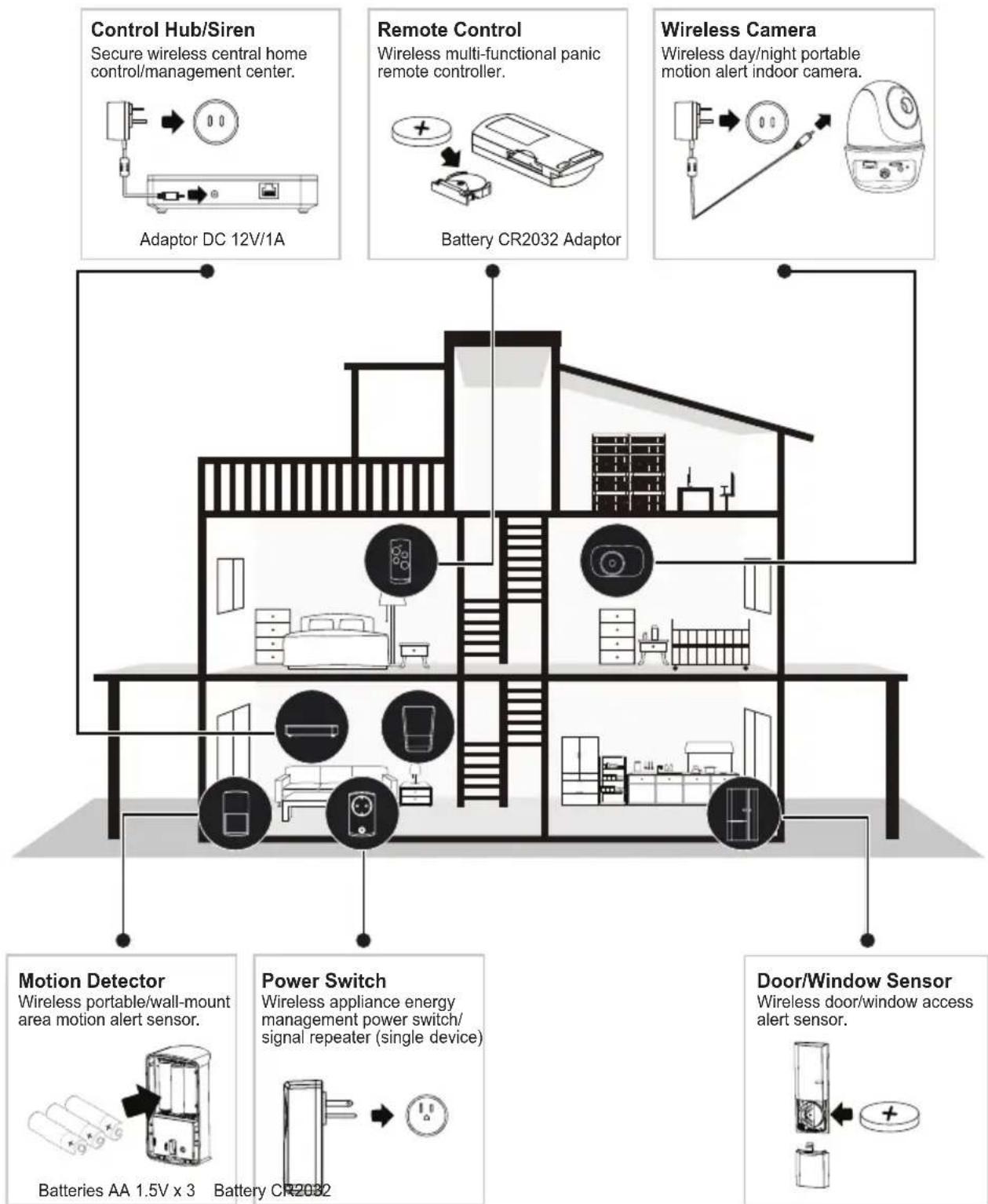
Installation Tips
The diagram below shows the suggested location(s) for the security system. Use this as a guide for your installation. The system is expandable with additional compatible wireless cameras, Motion Detectors, door/window contact sensors, sirens or other sensors (see page 6 to see what is included with your kit) for greater protection.
flowchart
graph TD
    A["Control Hub/Siren"] --> B["Adaptor DC 12V/1A"]
    C["Remote Control"] --> D["Battery CR2032 Adaptor"]
    E["Wireless Camera"] --> F["Wireless day/night portable motion alert indoor camera"]
    G["Motion Detector"] --> H["Batteries AA 1.5V x 3"]
    I["Power Switch"] --> J["Battery CR2032"]
    K["Door/Window Sensor"] --> L["Batteries AA 1.5V x 3"]
    B --> M["Interior layout of building"]
    D --> M
    F --> M
    H --> M
    J --> M
    L --> M
Installation Tips
WARNING:
It is not recommended to use this camera outdoors.
- Before you install the system, plan where and how it will be positioned, and where you will route the cable that connects the camera to the power adaptor(s).
- Avoid having a direct light source in view of the camera.
- Before starting permanent installation, have another person check the camera image on the tablet/phone when camera is positioned in the same place it will be permanently installed.
- If the signal will have to pass through a wall, placing the Wi-Fi router or camera next to a window will improve the signal strength.
- Do not install the camera pointing out of a window. The night-time picture will be unusable due to reflection from the night vision LEDs.
- As dust, grime, and cobwebs accumulate on the camera glass, they can reflect light from the infrared LED and might reduce video quality. Periodically clean the lens glass with a soft cloth.
Night Vision
The camera has built-in infrared LEDs to allow you to view at night for 24-hour surveillance. The LEDs will automatically activate at night and the picture viewed will change to black and white. The night viewing range is up to 35 feet.
Installing the Camera
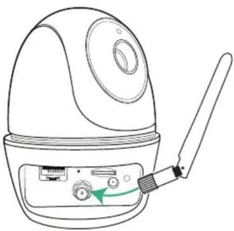
1
Screw Antenna clockwise into rear of camera.
2
If not mounting, but just using on a flat surface (desk, table, etc.), skip to step 5.
natural_image
Line drawing of a portable electronic device with a cable inserted, showing ports and a green arrow indicating rotation (no text or symbols)3
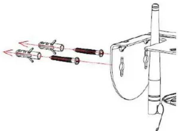
Secure the multi-position Camera Bracket to a stable surface, ceiling or wall using the two screws. If needed, two anchors are also included.
TIP: Reverse Camera Bracket for Wall Install, if desired. Make sure to "Flip and Mirror" the image, see page 27 "Screen Orientation" section when installing upside down.
natural_image
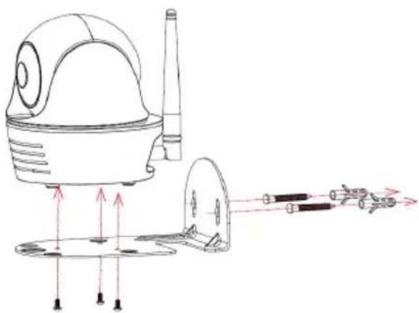
Diagram of a mechanical device with multiple cylindrical components and red directional arrows indicating motion (no text or symbols)4
Secure the camera to the Camera Bracket using the three smaller screws.
natural_image
Technical line drawing of a mechanical device with arrows indicating motion or force direction (no text or symbols)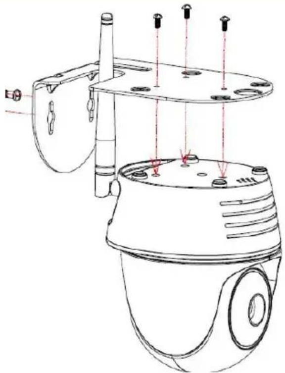
natural_image
Technical line drawing of a security camera with mounted components and red alignment markers (no text or symbols)Installing the Camera
5
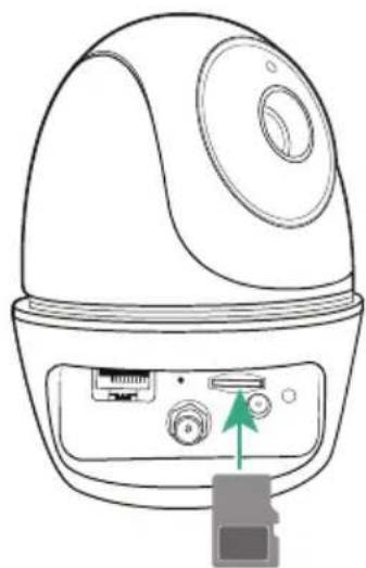
To record videos you must insert a MicroSD card (not included). The MicroSD Slot is located on the rear of the camera.
natural_image
Line drawing of a device with ports and a green arrow pointing to a button (no text or symbols)6
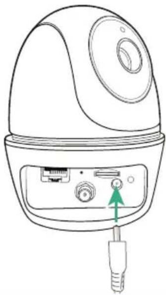
Connect the small end of the AC adapter to the camera's AC In Jack.
natural_image
Line drawing of a device with a connector and ports, no text or symbols present7
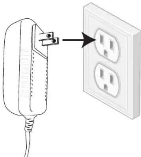
Plug the other end of the adapter to a 120 volt AC (standard indoor) power outlet. After approximately 20 seconds the unit will cycle around and up and down, and the Power indicator will light green for a short time and then blink to indicate it is ready.
natural_image
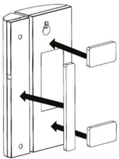
Illustration of a power plug connected to an electrical outlet with two socket outlets (no text or symbols)Installing the Door/Window Sensor
Double-Sided Tape

Apply the double-sided tape to the rear of both sections of the Door/Window sensor.
natural_image
Diagram of a door lock mechanism with arrows indicating movement (no text or symbols)
Select a location on a door or window. The large section of the sensor should be fixed on the immovable frame of the door/window.
Align the small piece to the large one. Fix the small piece on the movable part of the door/window frame.
Note:
- See page 45 for installing/replacing the battery.
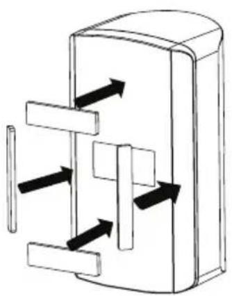
Installing the Motion Detector
Option A - Double-Sided Tape

Apply the double-sided tape to the rear of the Motion Detector as shown. Use the thick tape for flat wall mount or the thin tape for corner mounting.
natural_image
Diagram of a mechanical or electrical component with directional arrows indicating flow or movement (no text or symbols)
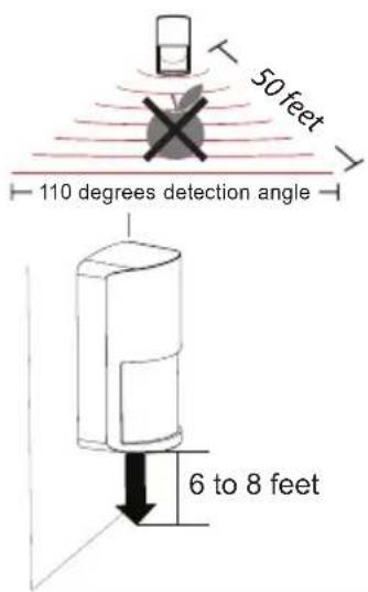
Select a desired location. It is recommended to place the Motion Detector in the corner of the room and between 6 to 8 feet from the floor.
Option B - Screws

Flat Wall: Remove back cover and insert the four screws as shown (A).
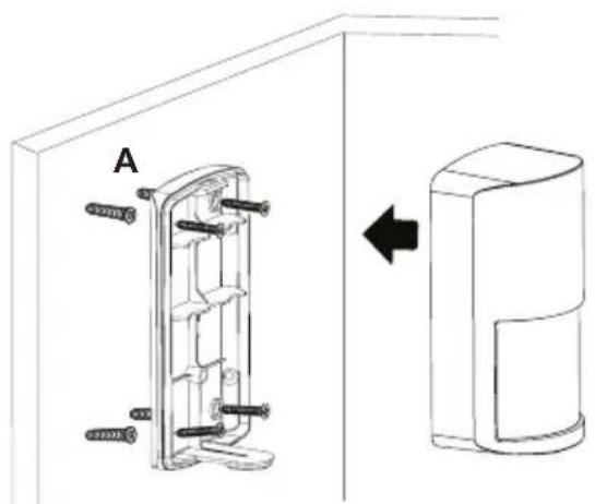
natural_image
Technical line drawing of a door panel assembly with mounting holes and a close-up view of the door (no text or symbols)
Flat Wall: Place the unit back onto the back cover.
Notes:
• See page 46 for installing/replacing the batteries.
- The Motion Detector is most effective in areas such as hallways and entry points where intruders may likely pass through.
- The Motion Detector monitors movements up to 16 meters away, with 110 degrees detection angle. Make sure it is angled facing with the least obstructions for best coverage.
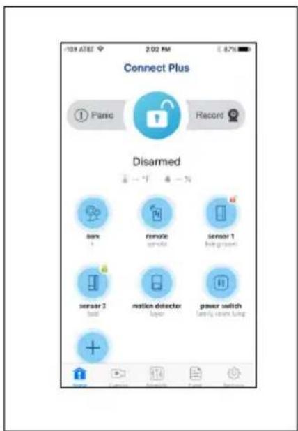
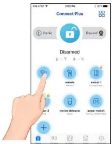
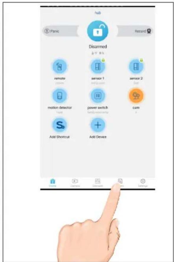
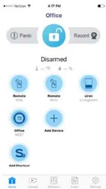
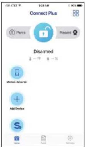
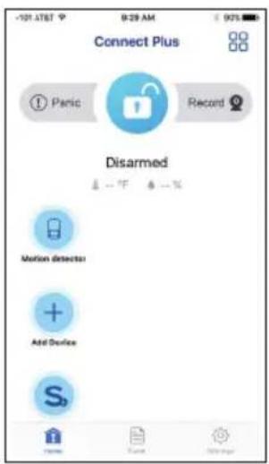
Basic Operation
1 When first turning on the app you will enter the Control Hub Selection window. Simply tap your Control Hub to enter.
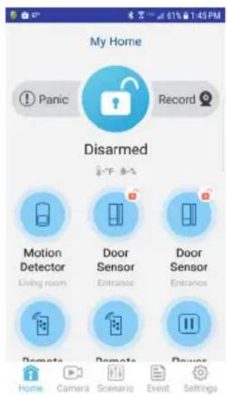
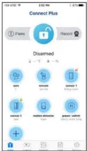
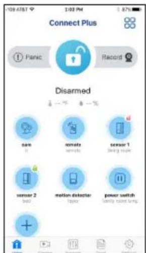
2 The Status screen will then appear; see below and the following pages for the details and operation of the Status page.
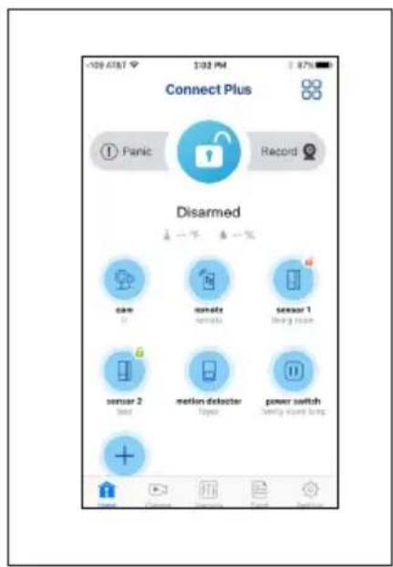
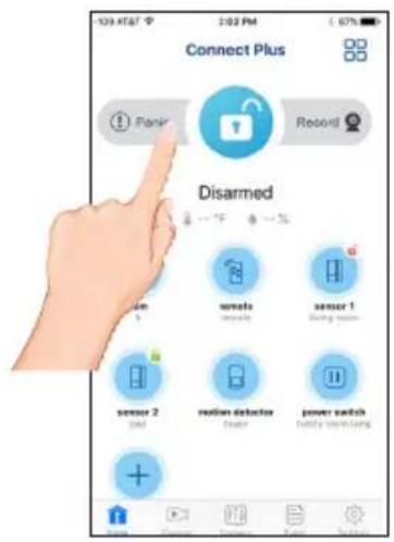
Status Screen Descriptions
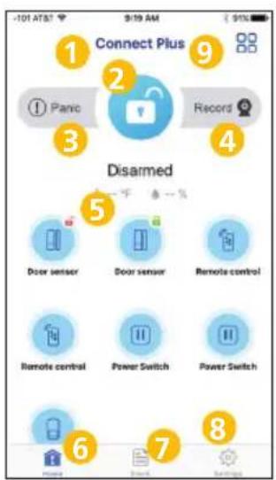
Add device:

Add shortcut:

- System name
- Tap to Arm/Disarm
- Tap to set off panic alarm
-
Tap to record
-
Tap to go to device edit page
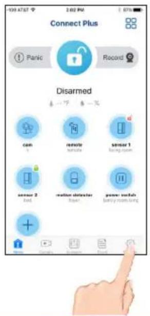
- Tap to go to the Home screen
-
Tap to go to the Event page
-
Tap to go to the Setting's page
- Tap to add Camera and Scenario icons to Menu at the bottom of screen.
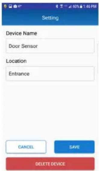
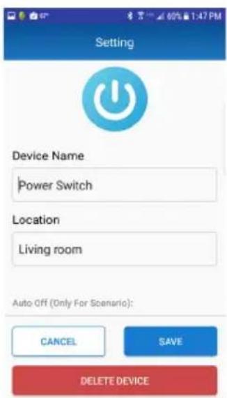
Basic Operation

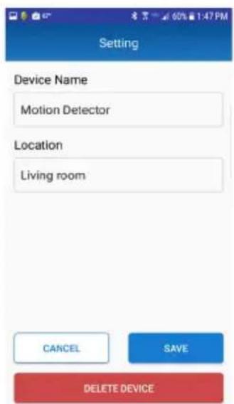
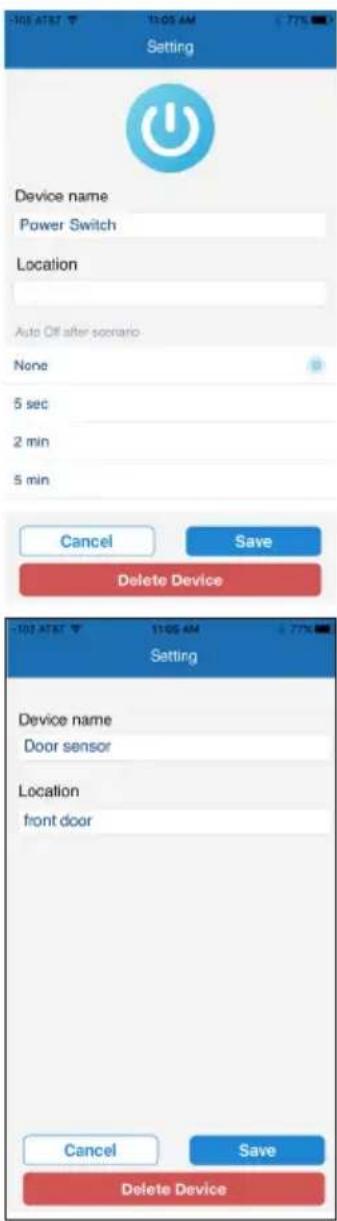
Tap a sensor/device's name to enter the respective device's Edit window, which will allow you to set the following:
Power Switch: Name and Location. You can also set the Auto Off Time (when set with a scenario) as well as a schedule to turn on and off.
At the bottom of this screen (you may have to scroll down), tap Schedule Setting. On the Schedule Screen, you can set the power switch to turn on and off at a particular time as well as set the days of the week.
Camera: See page 29.
All Other Devices: Device Name and Location. After entering tap Save. Tape Delete Device to delete the device.

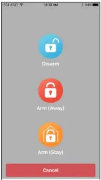
ARM AWAY and ARM STAY: Tap to Arm/Partially disarm the system. Select one of the following options:
Stay: Only arms the Door/Window sensors so you can stay at home.
Away: Arms all devices.
Basic Operation
5
PANIC: Tap the Panic icon on the Status screen to set off the Alarm.
6
For Main Settings: At the Status Screen, tap then enter the Admin Password (Default is 123456) to enter the Advanced settings as described on the next page.
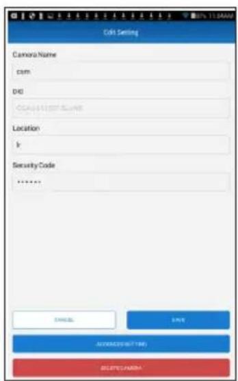
7
For Camera Settings: At the Status Screen, tap the new Camera icon. Tap Edit Setting and then tap Advanced Setting. Enter the Admin Password to enter the Advanced settings as described on pages 26-27.
Note:
Default admin password is 123456. This password is needed if you need to change any advanced setting.
Basic Operation
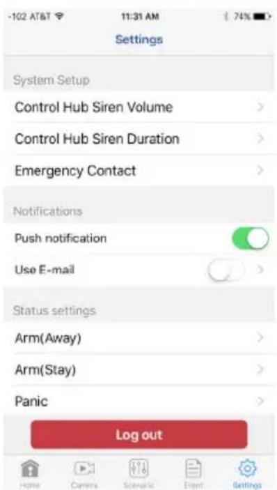
MAIN SETTINGS
Set the following at the Device's Advanced Settings:
Control Hub Siren Volume: Tap to set the Control Hub's Siren Volume (None, Low or High).
Control Hub Siren Duration: Tap to set the Control Hub's Siren Duration (60, 120 or 180 seconds).
Emergency Contact: Tap to set the emergency contact should the alarm go off. The default is 911.
Push Notification: Click the switch to turn this on or off. This will allow the device to send you alerts.
Use E-mail: Click the switch to turn email alerts on or off. Click Use E-Mail to enter up to 5 emails for this device to send alerts to.
Arm (Away): Tap to enter the Arm (Away) screen. Click to add a check-mark next to any device that you want activated when you arm the system with Arm (Away). Also set the Arm Delay which is the time you have to get out of the house once the device is armed.
Arm (Stay): Tap to enter the Arm (Stay) screen. Click to add a check-mark next to any device that you want activated when you arm the system with Arm (Stay). Also set the Arm Delay which is the time you have to get out of the house once the device is armed.
Panic: Tap and then set the devices to activate in Panic mode.
Record: Tap to set the cameras that will record when the Record feature is activated on this system. See page 33.
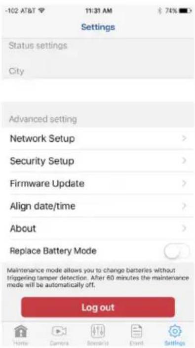
City: Tap to input the city and state or Zip code. This will display the local temperature and humidity on the Home page.
Network Setup: It is recommended to keep this option on so the unit will automatically add the IP Address, etc. You can de-select it and manually enter this information for using a Static IP address.
Device Security Setup: Tap Modify to change the Device Security Code.
Firmware: Tap to see if there is an update available. If there is, tap Update to update the firmware.
Align Date/Time: Tap to transfer the date, time and time zone from the mobile device to the system.
About: Tap to display information about the system such as DID, Firmware, etc.
Replace Battery Mode: Tap to turn this switch on (red). so you can change batteries in a device without triggering the tamper detection. After 60 minutes this mode will automatically turn off.
Basic Operation
CAMERA SETTINGS
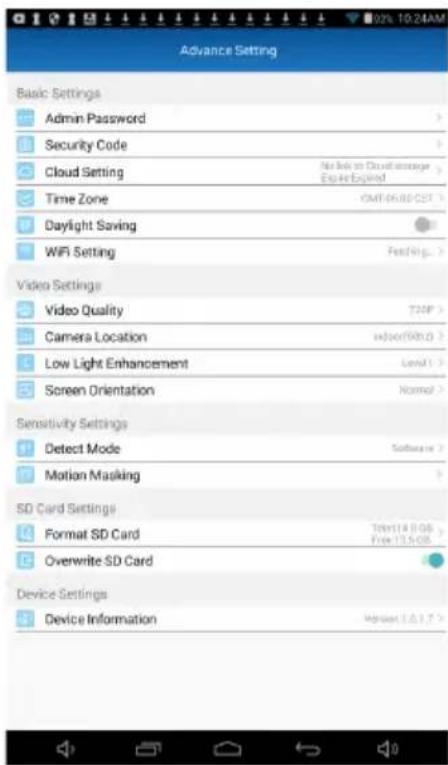
Set the following at the Camera's Advanced Settings:
Admin Password: Tap to change the Admin Password.
Device Security Code: Tap to change the Device Security Code.
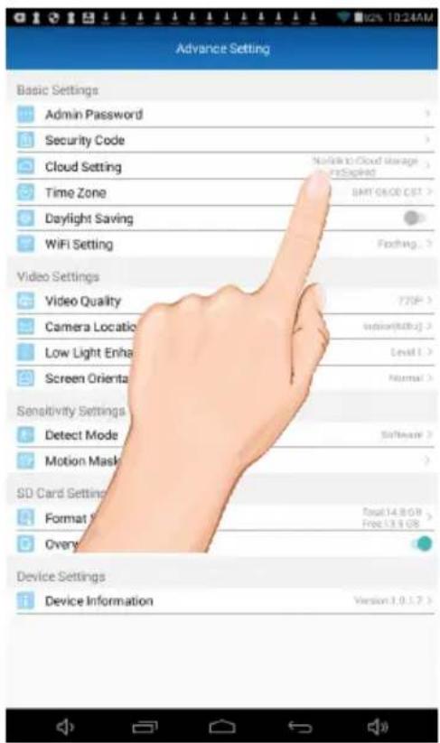
Cloud Setting: Any cloud storage criteria will appear here (i.e. Google Drive). Tap to change/set the cloud storage information. Videos recorded onto the SD card will also be transferred to the cloud storage. See page 41 to Setup a Cloud Account.
Time Zone: Tap to select the time zone you are in.
Daylight Saving: Tap the switch to select daylight saving time.
Wi-Fi Setting: The Wi-Fi setting allows you to choose the home network and setup the Wi-Fi environment. When you tap WI-FI Setting, the system automatically scans the nearby network and shows the available Wi-Fi routers in the list. Choose the Wi-Fi router connected to the home network and enter the Wi-Fi router password if necessary. Due to security concerns, it is suggested to use the WPA/WPA2/WPA2-PSK protocol for Wi-Fi network.
Video Quality: Tap to set the Video Quality. Tapping VGA will allow for faster video streaming, but the picture will not be as clear. Tapping 1080P will give the best video but will be slow. Tapping 720P will provide mid speed and mid video picture.
Camera Location: Tap location of camera. If selecting indoor, select the frequency used in your area. North America uses 60Hz, European countries use 50Hz.
Low Light Enhancement: Tap to set the Low Light Enhancement. 5 will provide the brightest enhancement and 1 the lowest.
Screen Orientation: Tap to select the desired screen orientation; Normal, Flip, Mirror or Flip & Mirror (when installed in a hanging position, make sure to select Flip & Mirror).
Detect Mode: Tap to set the desired Sensitivity Settings as well as the detection mode as follows:
OFF: Turns sensitivity off. No motion detection.
Software: Uses advanced software. In this setting, set the Day and Night as desired. Higher will make the camera more sensitive to “less” motion.
Motion Masking: See next page for detailed operation.
Format Sd Card: Tap and then confirm to format the MicroSD card inserted in the camera
Overwrite Sd Card: Tap this switch to activate. When activated, the camera will delete the oldest recordings in order to record new files when the MicroSD card is full.
Device Information: Tap to view the device information, including current firmware version, total size and free size (space available).
Basic Operation
CAMERA SETTINGS
MOTION MASK: This option is only visible when the Software option under Detect Mode has been activated. This feature will allow you to mask areas of the screen from detecting motion and activating the motion detector recording for that area. For example, if a pet sets off the sensor, you can mask the lower areas that the pet would be visible in, or if a tree branch moving in the wind sets it off, you can mask the areas where the tree branch is in the video.

Use the Quick De-Select and/or Tap Screen option to manually mask a block anywhere on the screen; the block will turn black. To un-mask a block, simply tap it again.
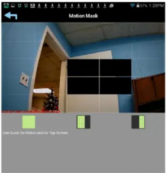

Use the quick right and left options to quickly select the right or left side of the screen to mask. Simply tap this option again to un-mask.

Tap the Save icon when done.
Camera Screen

On the Status window, tap the Camera icon at the middle of the screen. At this screen you can view the camera.
You can also tap the Camera icon at the bottom of the page followed by the Play button to view the camera.
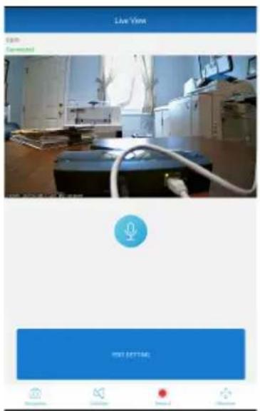

Tap Edit Setting to go to the Edit Setting page where you can rename the camera and location or delete the camera. Tap Advanced Setting to go to the Advanced Setting's screen (see pages 26-27)
Tap the icons to perform the functions as shown below.

Talk: To speak through the camera's speaker, using your Android or Apple device, tap and hold this icon and speak; the voice will be heard through the camera's speaker.

Snapshot: Tap to capture screen images. The snapshots will be saved into the camera roll of your mobile device and/or the Cloud, if set (see page 41).

Mute/Un-mute: Press to hear the sound of the camera's microphone through the App. Tap again to mute the sound.

Record: Tap to record. Video records for about two minutes. Note that a Micro SD Card is required to use the recording function on the camera. Insert on the side of the camera. When an SD card is inserted and the Cloud option is activated (see page 41), recorded videos will automatically be transferred onto the cloud, i.e. Google Drive.

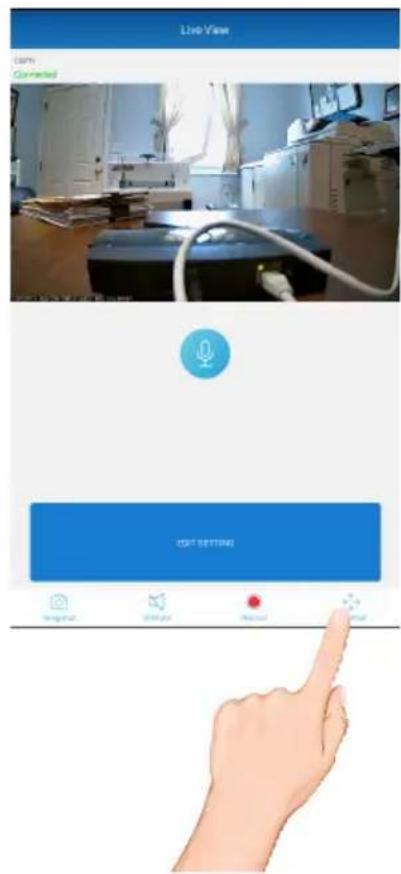
Shortcut: Tap to Set the Record Point or to Go to the Record Point, see the next page.
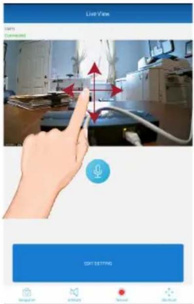
Live Video Screen

PINCH AND ZOOM: To zoom in or out, use the simple pinch and zoom gesture.
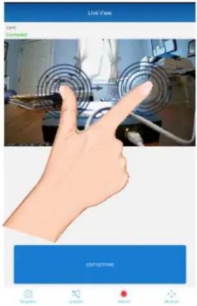

Pan and Tilt: To move the camera, simply slide your finger across the Android or Apple Device's screen up and down or from side to side.
Live Video Screen
3
Tap the Shortcut/PTZ icon and the Record Point box will appear.
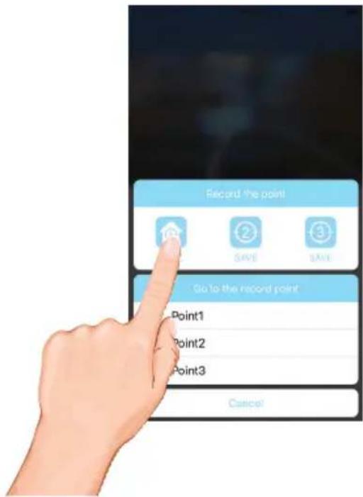
4
Tap the Save icon to save the current point.
Repeat steps 2 through 5 to set the Point 2 and Point 3 positions.
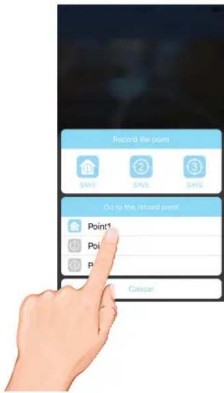
Live Video Screen

To Go To A Specific Point: To return the camera to the a preset point, tap the Shortcut icon and then tap the desired "Go to record point" icon. The camera will then move to that point.
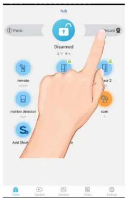
Recording from the Status Screen

On the Status window, tap the Record icon at the top right of the screen. The unit will then record for two minutes.
To Play Videos
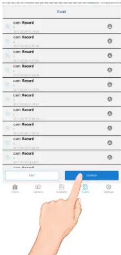
1 On the Status window, tap the icon at the top right of the screen (IOS only) to show the 5 icons at the bottom. Tap the Event icon.
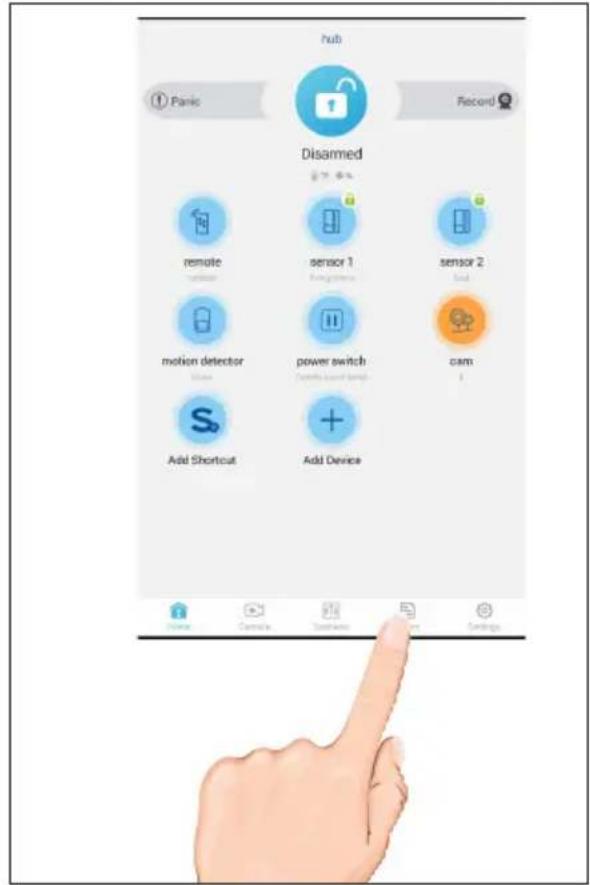
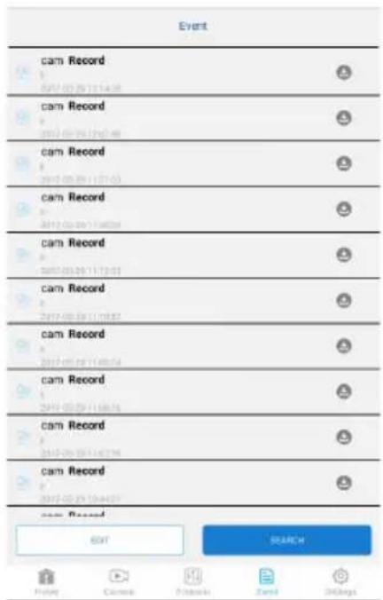
2 The list of triggered events will appear. If a video has been recorded, you can tap it to play it on the mobile device.
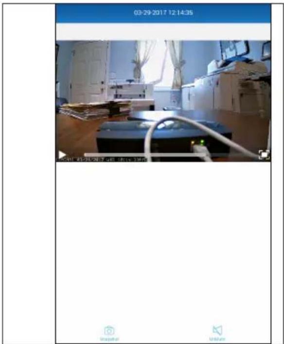
To Play Videos

When playing back a video, tap the Pause icon to pause the video. Tap again to resume.
Tap the Mute icon to mute the sound, tap again to resume sound.
Tap the Snapshot icon to take a picture.
DOWNLOAD A VIDEO: To download a video to your Android or Apple device, tap the Download icon and it will download to your device.

To Search, tap SEARCH.
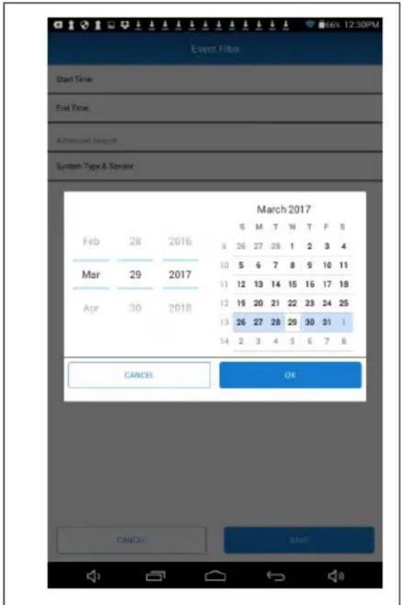
To Play Videos

Select the desired Start Time and End Time. Also select the Sensors to be shown in the triggered events.
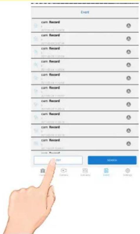
To Delete Recordings
1 Access the Events List as shown on page 39.
2 Tap the EDIT icon. Tap DELETE ALL to delete all of the Recordings.
Remote Control Function
For the Remote Control to work, it must be within range of your Hub. Primarily it is used when before entering and leaving the house to Disarm or Arm your System.
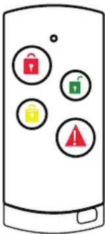
ARM STAY: Arm the preselected camera(s) and sensor(s). Select Disarm to disable system's Arm or Partial Arm status. See pages 23-25. You will have 30 seconds to exit the premise after initiating the Arm function.

ARM AWAY: Partially Arm the preselected camera(s) and sensor(s). Select Disarm to disable system's Arm or Partial Arm status. See pages 23-25.

SARM: Disarms the alarm. Also turns off Alarm is triggered.

PANIC: Press and hold the Panic button to activate selected camera(s), siren(s) and power switch(es) for emergency recording, alarm sounding and/or Power Switch (lighting) needs.
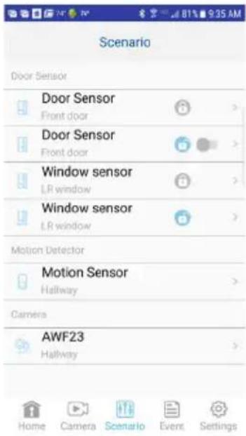
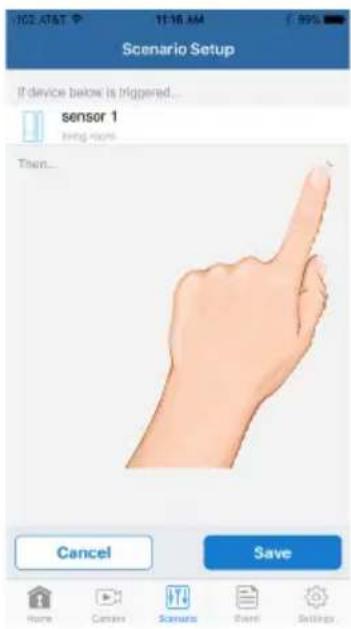
Scenario
1
On the Status window, tap the Scenario icon.

3
You will see a screen with "If device below is triggered.
You will also see "Then..." which is where you will add items that will activate.
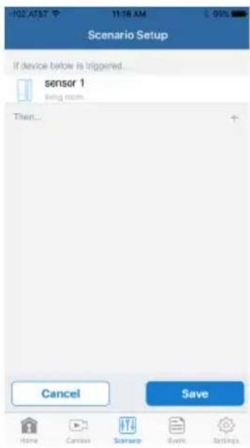
2
The Scenario will allow you to preset a sequence of events. For example, once the Motion Detector detects motion, the camera can begin recording and the light can turn on. Tap one of the sensors to set up a scenario
4
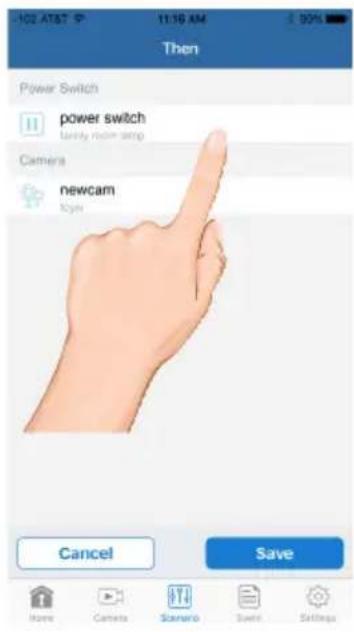
Tap the + icon.
Scenario

Select the desired device to activate by tapping its check box. Note that adding a device will automatically activate it. Tap Save when done.
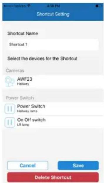
Shortcut
A Shortcut can be created to group sensors together to turn them on all at the same time. An example is turn on all lamps plugged into the Power Switches.
Cloud Account Setup
The AWF627-23 has a feature that will automatically upload recorded video files from the camera's MicroSD card to either Google Drive ^ or Dropbox ^ . To use this feature you must already have an existing Google Drive or Dropbox account.
To sign up for a free account, go to:
www.google.com/drive
www.dropbox.com
There is no charge from ALC to use this feature. It is free!

After setting up your Google Drive or Dropbox account, you will need to establish a Cloud account as follows.

Tap the Cloud Setting option.
Cloud Account Setup
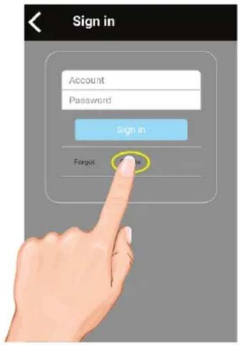
3
On the Sign in screen, tap Create.
4
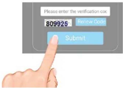
To create your Cloud account, enter a valid email address and create a password. Agree to the privacy policy.
Enter the verification code and tap Submit.
<
Create Account
Fields with * are required.
*User ID
Please fill in your email account
- Password
Please fill in 6 to 12 letters of n.
* Confirm Password
Please fill in your password ago
* Default Display Language
English
I agree to privacy policy
<here to view privacy policy
lease enter the verification co
09925
Review Cards
Cloud Account Setup

After creating the account, a welcome screen appears. Tap OK to dismiss the message.


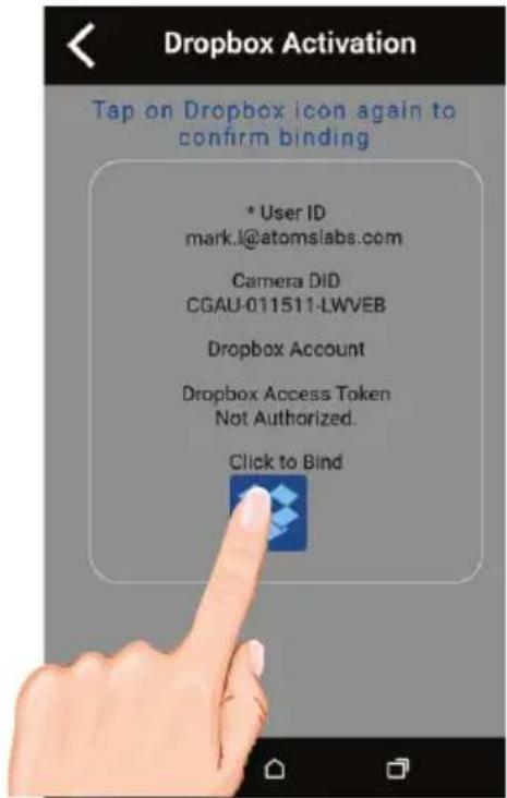
When the Device List appears, tap on the desired option; Google Drive or Dropbox, to create the binding.
![Device List Front door [CGAU-011511- LWVEB] Google Drive Authentication Dropbox Authentication Delete Camera](/content/2026/06/1204582/images/f15b415237fb8759bbab11dc6e1733bf8b4d7200d31500559047d8728a964d5f.jpg)
Cloud Account Setup
7
To confirm binding, tap on the Bind icon.
8
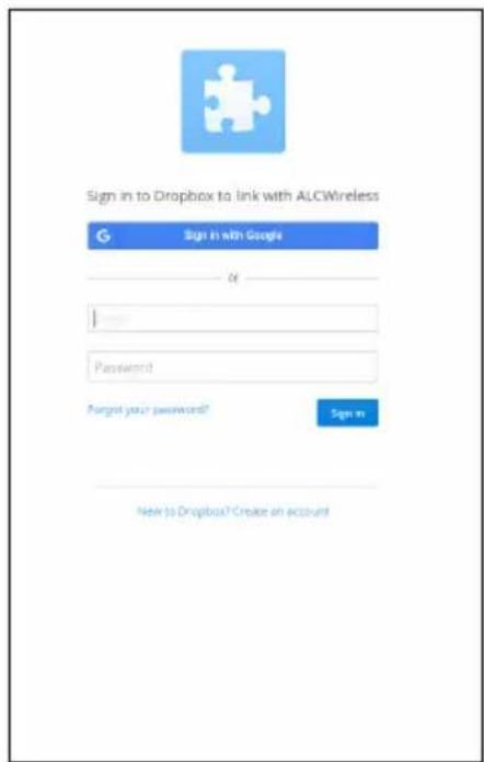
Now, you will need to sign in onto your Google Drive or Dropbox account. Enter your email and password and tap Sign in. Tap Allow.
Congratulations! Your Cloud setup is complete. Now you can access videos anywhere by simply going into the Google Drive or Dropbox website or app.
NOTE: Videos will automatically be saved onto the Cloud when a MicroSD card is inserted and the Cloud Storage is setup.
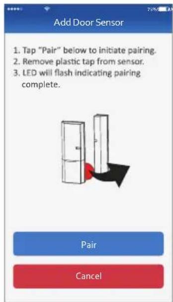
Pairing the Door/Window Sensor
PAIRING: All included sensors are paired with the Control Hub at the factory. See following pages to pair them again or if additional accessories are purchased.
1 The Door/Window Sensor comes with a pre-installed CR2032 battery. If it needs replacing, simply remove the cover by sliding it downwards and replace with a new CR2032 battery.
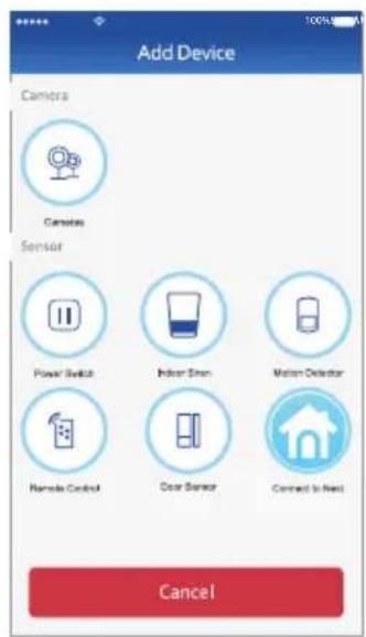
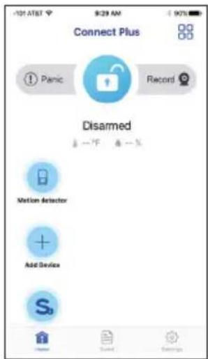
2 At the dashboard, tap "+" (Add Device).
3 Tap Door Sensor from the Device list. Name the sensor and the location, tap Save.
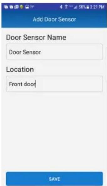
4 Tap Pair, then remove plastic tab to start pairing the Door/Window Sensor. "Add Sensor Completed" will appear and the Door/Window Sensor will be added.
Pairing the Motion Detector
1
The Motion Detector comes with three pre-installed AA batteries. If they need replacing, press the tab at the bottom of the sensor and insert three AA size batteries following the diagram in the compartment.
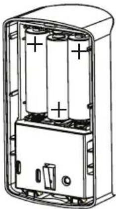
natural_image
Diagram of an open battery pack with two cylindrical cells and a terminal block (no text or symbols)3
Tap Motion Detector from the Device list. Name the Motion Detector and the location, tap Save.
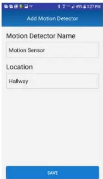
2
At the dashboard, t ap "+" (Add Device).

4
Tap Pair, then remove plastic tab to start pairing the Motion Detector. "Add Sensor Completed" will appear and the Motion Detector will be added.
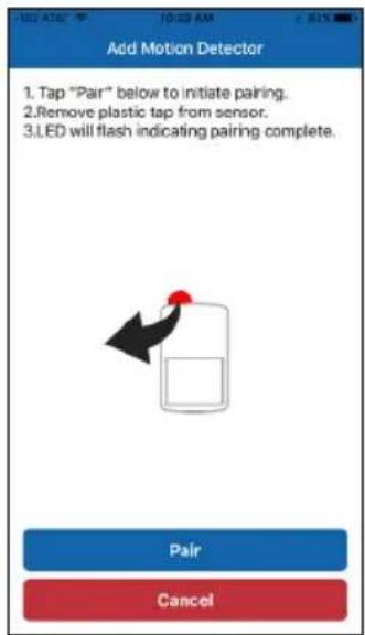
If the Motion Detector did not pair in step 4, open the compartment and manually pair by pressing the Pair button. Tap Pair to start pairing the Motion Detector.
Pairing the Power Switch
1 At the dashboard, tap "+" (Add Device).
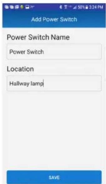
2 Tap Power Switch from the Device list. Name the Power Switch and the location, tap Next.
3 Tap Pair to start pairing the Power Switch. Name the Power Switch and location and tap Save.
4 Plug the Power Switch into a standard AC outlet having 120V, 60Hz; the LED will blink indicating the Power Switch is in the pairing mode. "Add Sensor Completed" will appear and the Power Switch will be added.
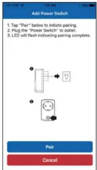
If the Power Switch did not pair in step 4, open the compartment and manually pair by pressing the Pair button. Tap Pair to start pairing the Power Switch.
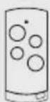
Pairing the Remote
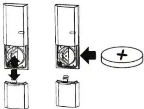
1 The Remote Control comes with a pre-installed CR2032 battery. If it needs replacing, simply pull out the battery compartment on the side of the Remote Control and replace with a new CR2032 battery.
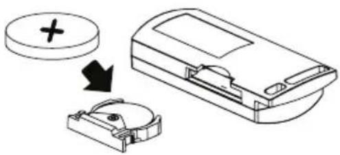
natural_image
Diagram showing a device with a plus sign and a cross symbol, connected to a mechanical housing (no text or labels)2 At the dashboard, tap "+" (Add Device).

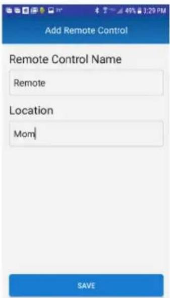
3 Tap Remote Control from the Device list. Name the Remote Control and the location, tap Save.
4 Tap Pair then remove plastic tab to start pairing the Remote Control. "Add Sensor Completed" will appear and the Remote Control will be added.
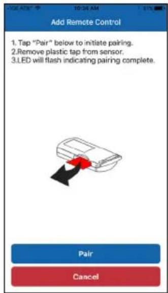
If it did not detect the Remote Control, press and hold the Armed Stay button on the Remote Control until the blue LED blinks. Tap Pair to start pairing the Remote Control.
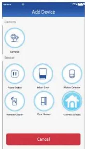
Connecting to Nest
If you have a Nest Learning Thermostat installed, you can add it to your ALC Connect Plus Security System to control it from the ALC Connect Plus App.
1
At the dashboard, tap "+" (Add Device).
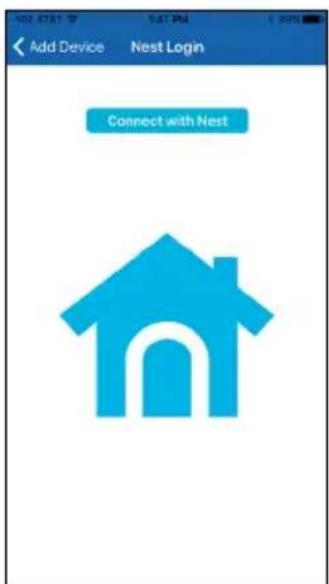
2
Tap Connect to Nest. At the next screen, also tap Connect with Nest.
3
Tap Connect with Nest.
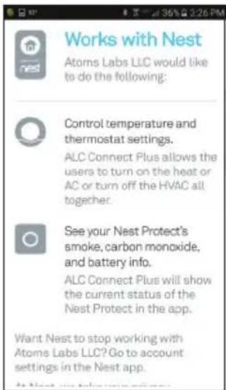
4
You can now connect with the Nest Thermostat to display the temp/humidity as well as controlling it via this Connect Plus app.
If you have any trouble with your system, try these simple steps which should handle most common issues.
| Problem | Possible Solution |
| Control Hub Device not working. | Make sure it is plugged into an AC Outlet and that the rear connection is inserted correctly.Make sure the Ethernet cable is connected to the rear of the Gateway and to a working router. |
| A Sensor device is not working. | Make sure fresh batteries are installed according to the diagram in the compartment. |
| Cannot remotely connect to the Control Hub from a mobile device. | Make sure the router is functioning properly and reconnect the Ethernet cable to the Control Hub. |
| Poor picture quality. | Clean the camera lens using a microfiber cloth. |
| Camera not recording. | Ensure the MicroSD card is inserted into the camera. |
| Email Alert is not working. | Make sure the email alert function is enabled.Make sure the email address has been correctly entered. |
| A white image appears at night (camera). | The camera's infrared LEDs shine invisible light that reflects off of surfaces such as glass and will cause white light. |
Additional Troubleshooting tips and FAQ's can be found on our Support page. www.alcwireless.com/support.
Factory Default/Reset
Insert a paper clip or similar object into the Reset hole for 12 seconds and the system will start the reset process. The system will restore to factory default settings and you may start the setup.
Control Hub/Siren
Operation Voltage....12V DC/1A
Ethernet....10/100 Mbps
Frequency 916.8 MHz
Piezo Siren ...... Maximum 85 dB
Camera
Wireless Compatible...... IEEE 802.11 b/g/n
Sensor....2 Mega Pixel CMOS
Frequency 2400\~2485 MHz
Protocol TCP/IP, UDP, SMTP, NTP, DHCP, ARP
Image Compression ...... H.264
Image Resolution....HD 1920 x 1080
Operating Temperature -10°\~+50°C
Operating Humidity 20\~80 RH (N.A.-condensing)
Communication Range 500 ft (150 meters) in open space
Night Vision 35 ft
Dimensions.... 3.8 x 3.3 x 3.5 in (96 x 83 x 89 mm)
Remote Control
Signal Frequency 916.8 MHz
RF Range (open field conditions) 500 ft (150 M)
Battery Type 1 x CR2032 Battery (included)
Battery Life ......Anticipated life up to 2 years (Supposed 10 triggers per day)
Battery Power Monitoring ....Yes (On device and transmitted to App)
Operating Temperature 0°\~40°C
Operating Humidity 10%\~80% RH
Dimensions.... 2.4 x 1.2 x 0.6 in (60 x 30 x 14 mm)
Motion Detector
Signal Frequency....916.8 MHz
RF Range (open field conditions) 500 ft (150 M)
Max. Detection Range..... Up to 50 ft (16 M)
Detection Angle 110°
Battery Type....3 x 1.5V AA Batteries (included)
Battery Life ....Anticipated life up to 2 years (Supposed 200 triggers per day)
Battery Power Monitoring ....Yes (On device and transmitted to App)
Tamper Detection......Yes (Rear)
Operating Temperature 0°\~40°C
Operating Humidity.... 10%\~80% RH
Dimensions.... 4.3 x 2.4 x 2.0 in (110 x 61.4 x 51.6 mm)
Power Switch
Signal Frequency 916.8 MHz
RF Range (open field conditions) 500 ft (150 M)
Load Switching Capability 1800W
Operating Temperature 0°\~40°C
Operating Humidity 10%\~80% RH
Dimensions 3.7 x 2.2 x 1.2 in (94 x 55 x 31 mm)
Door/Window Sensor
Signal Frequency....916.8MHz
RF Range (open field conditions) 500 ft (150 M)
Operating Temperature 0 - 40 C
Operating Humidity....10%\~80% RH
Dimensions.... 1.6 x 1.8 x 0.5 in (41 x 46 x 13 mm)
ALC™
One-Year Limited Warranty
IMPORTANT: Evidence of original purchase is required for warranty service.
Atoms Labs LLC ("ALC") ELEMENTS OF WARRANTY: ALC warrants, if properly installed and used thereafter in strict accordance with the use and care guidelines provided in the instructions manual, the Product shall be free from manufacturing defects in material and workmanship for one (1) year from the documented date of purchase. The purchase date must be documented with either an original sales receipt from the first retailer selling the Product or by credit card receipts or statements. The warranty is non-transferrable.
LIMITED WARRANTY: The warranty terminates one year after the date of original retail sale. The warranty is invalid if the Product is (A) damaged or not maintained as reasonable or necessary, (B) modified, altered, or used as part of any conversion kits, subassemblies, or any configurations not sold by ALC, (C) improperly installed, (D) serviced or repaired by someone other than an authorized ALC service center for a defect or malfunction covered by this warranty, (E) used in any conjunction with equipment or parts or as part of any system not manufactured by ALC, or (F) installed or programmed by anyone other than as detailed by the owner's manual for this product.
THIS WARRANTY DOES NOT COVER DATA LOSS, OR COSTS RELATED TO DATA RECOVERY. ALC MAKES NO WARRANTY THAT ANY SOFTWARE PROVIDED WITH THE PRODUCT WILL FUNCTION WITHOUT INTERRUPTION OR OTHERWISE BE FREE OF ANOMALIES, ERRORS OR VIRUSES. THIS WARRANTY DOES NOT COVER ANY COSTS RELATING TO REMOVAL, REPLACEMENT, OR INSTALLATION OF ANY PRODUCT, REGARDLESS OF WHETHER THE PRODUCT IS FOUND BY ALC TO BE DEFECTIVE, OR SOFTWARE INSTALLED ON THE USER'S COMPUTER.
ALC DOES NOT MAKE ANY CLAIMS OR WARRANTIES OF ANY KIND WHATSOEVER REGARDING THE PRODUCT'S POTENTIAL, ABILITY OR EFFECTIVENESS TO PREVENT, MINIMIZE, OR IN ANY WAY AFFECT PERSONAL OR PROPERTY DAMAGE OR INJURY. ALC IS NOT RESPONSIBLE FOR ANY DAMAGE, LOSS OR THEFT RELATED TO THE PRODUCT OR TO ITS USE FOR ANY HARM, WHETHER PHYSICAL OR MENTAL RELATED THERETO. ANY AND ALL CLAIMS OR STATEMENTS, WHETHER WRITTEN OR VERBAL, BY SALESPEOPLE, RETAILERS, DEALERS OR DISTRIBUTORS TO THE CONTRARY ARE NOT AUTHORIZED BY ALC AND DO NOT AFFECT THIS PROVISION OF THIS WARRANTY. THE LIMITED WARRANTY IS THE SOLE AND ENTIRE WARRANTY PERTAINING TO THE PRODUCT AND IS IN LIEU OF AND EXCLUDES ALL OTHER WARRANTIES OF ANY NATURE WHATSOEVER, WHETHER EXPRESS, IMPLIED OR ARISING BY OPERATION OF LAW, INCLUDING, BUT NOT LIMITED TO ANY IMPLIED WARRANTIES OF MERCHANTABILITY OR FITNESS FOR A PARTICULAR PURPOSE. THIS WARRANTY DOES NOT COVER OR PROVIDE FOR THE REIMBURSEMENT OR PAYMENT OF LOST REVENUE, PROFIT, OR DATA, OR FOR SPECIAL, INDIRECT, CONSEQUENTIAL, INCIDENTAL, OR PUNITIVE DAMAGES HOWEVER CAUSED AND REGARDLESS OF THE THEORY OF LIABILITY. Some states do not allow this exclusion or limitation of incidental or consequential damages so the above limitation or exclusion may not apply to you. Your damages will be limited to the total purchase price you paid for the Product.
Use of audio or video equipment for recording the image of a person without their knowledge and consent is prohibited in certain states or jurisdictions. The end-user assumes all liability for compliance with applicable state, local and federal laws. Atoms Labs has no responsibility or liability for how the end-user uses a product. Wireless cameras require a wired connection to AC power outlet. Network conditions and environmental factors can adversely affect wireless signal range. Actual night vision range and image clarity depends on installation location, viewing area and light reflection / absorption.
This Product may only be sold in the United States of America and Canada. There is no warranty whatsoever on the Product outside of the United States of America and Canada.
STATEMENT OF REMEDY: If the Product is under warranty, ALC will either, at its option, repair or replace the defective Product and return it to you without charge for parts, service, or any other cost. ALC, at its option, may replace the Product with a new or refurbished Product.
ALC™
One-Year Limited Warranty
Continued
LEGAL REMEDIES: This limited warranty gives you specific legal rights, and you may also have other rights which vary from state to state. All parties irrevocably submit themselves to the exclusive venue and personal jurisdiction of the state and federal courts in Denton County, Texas with regard to any dispute relating to this Warranty or its enforcement. The parties also hereby waive any challenge to venue and personal jurisdiction they may have to a lawsuit filed in a state or federal court in Denton County, Texas, regarding a dispute between the parties relating to this Warranty or its enforcement. You agree that Atoms Labs is entitled to its reasonable and necessary attorney's fees if it is a prevailing party in litigation against you relating to this Warranty. If any provision of this Warranty is found to be invalid, illegal, or unenforceable, the validity, legality, and enforceability of any of the remaining provisions will not in any way be affected or impaired and a valid, legal, and enforceable provision of similar intent and economic impact will be substituted therefore.
PROCEDURE FOR OBTAINING PERFORMANCE OF WARRANTY: If, after following the instructions in the owner's manual you are certain that the Product is defective, pack the Product carefully (preferably in its original packaging). The Product should include all parts & accessories originally packaged with the Product. Include evidence of original purchase & a note describing the defect that has caused you to return it. The Product should be shipped freight prepaid, by traceable means, to warrantor at:
ATOMS LABS, LLC 2670 Firewheel Drive • Suite D Flower Mound, TX 75028
CUSTOMER SUPPORT 1.844.767.8544
9:00am - 6:00pm (Central Time) Monday - Friday
ALC reserves the right to make changes to its products without incurring any obligation to modify any product that has already been manufactured. This warranty does not cover any alteration or damage to any other software that may be or may become resident on the users system as a result of installing any software provided.
ALC appreciates your support and feedback! If you come across software bugs or ways we could improve our products, we would love to hear about them! Please email us at support@atomslabs.com and you will hear back from us.

FCC Compliance Statement: This device complies with Part 15 of the FCC rules. Operation is subjected to the following two conditions: (1) this device may not cause harmful interference, and (2) this device must accept any interference received, including interference that my cause undesired operation.

Products with CE Marking comply with EMC Directive (2014/30/EU); Low Voltage Directive (2014/35/EU); RED: Directive 2014/53/EU; ROHS Directive (2011/65/EU) issued by the Commission of the European Community. Compliance with these directives implies conformity to the following European Norms: EMC: EN 301 489, LVD: EN 60950, Radio: EN 300328
IC Compliance Statement: This device complies with Industry Canada's licence-exempt RSSs. Operation is subject to the following two conditions: (1) this device may not cause interference, and (2) this device must accept any interference, including interference that may cause undesired operation of the device.
Changes or modifications not expressly approved by the party responsible for compliance could void your authority to operate the equipment.

If the camera system no longer functions or can no longer be repaired, it must be disposed of according to the valid statutory regulations. Disposal of spent batteries/accumulators:
You are required by law (Battery Ordinance) to return all spent batteries and accumulators. Disposing of spent batteries/accumulators with common household waste is prohibited! Batteries/accumulators that contain hazardous substances are marked with the symbols on the side. These symbols indicate that it is prohibited to dispose of these batteries/accumulators in the household waste. The abbreviations for the respective heavy metals are: Cd=cadmium, Hg=mercury, Pb=lead. You can return spent batteries and accumulators that can no longer be charged to the designated collection points in your community, outlets or wherever batteries or accumulators are sold. Following these instructions will allow you to fulfill the legal requirements and contribute to the protection of our environment!

Please recycle. Facilities may not exist in your area.


ALC ^TM
Wireless
Made Simple.
ALCWireless.com
ALC ^TM
Wireless Made Simple.