NWKSP2 - Solar panels ComNet - Free user manual and instructions
Find the device manual for free NWKSP2 ComNet in PDF.


| Product Type | Solar Powered Off-Grid Power System |
| Brand | ComNet |
| Model | NWKSP2 |
| Kit Components | Photovoltaic solar panels, valve-regulated lead-acid battery, outdoor steel enclosure, 30A solar charge controller, PoE midspan injector, mounting hardware |
| Enclosure Material | Steel with gasket hinged lid, tamper-proof locks |
| Enclosure Mounting | Pole (2-4 inch) or wall mount |
| Solar Panel Mounting | Top-of-pole mount (4" diameter pole); side-of-pole optional |
| Solar Charge Controller | 30A, PWM, LCD display for diagnostics and system health |
| Battery Type | Valve-regulated lead-acid (deep cycle, cold weather performance) |
| Input Voltage | Solar panel voltage (not specified, typical 12V/24V) |
| Output | PoE (Power over Ethernet) via midspan injector |
| Protection Features | Overcharge, over discharge, battery protection; tamper-proof locks; rubber insulators on battery terminals |
| Wiring | MC4 connectors for solar panels; 15' or 30' cables supplied; 24" 10AWG battery cables |
| Operating Environment | Outdoor, remote locations without grid power |
| Compliance | FCC Part 15 Class A, Industry Canada ICES-003, CE marking |
| Installation Requirements | Professional installation; knowledge of electronic equipment and electrical regulations |
| Maintenance | Periodic inspection of wiring, battery, and solar panels; keep terminals clean and insulated |
| Spare Parts / Repairability | Contact ComNet for service; battery and controller may be replaceable; GPL software source available |
| Additional Documentation | Solar Charge Controller Manual, Solar Panel mounting instructions (included) |
Frequently Asked Questions - NWKSP2 ComNet
User questions about NWKSP2 ComNet
0 question about this device. Answer the ones you know or ask your own.
Ask a new question about this device
Download the instructions for your Solar panels in PDF format for free! Find your manual NWKSP2 - ComNet and take your electronic device back in hand. On this page are published all the documents necessary for the use of your device. NWKSP2 by ComNet.
USER MANUAL NWKSP2 ComNet
natural_image
Solar panel mounted on a base with visible wiring and sensors (no text or symbols)INSTALLATION AND OPERATION MANUAL
netwave®
NWKSP2
COMNET SOLAR POWERED SYSTEM
Thank you for purchasing NetWave ^® from ComNet. This manual will cover how to install hardware on your enclosure, Configure batteries, cabling and mounting of the enclosure.
The NetWave® NWKSP2 Solar off the grid power system is designed for applications where a remote camera or wireless repeater is needed but power is not available or the cost to run power is too expensive. NetWave Solar is a complete system for providing remote power to edge communications equipment. The kit includes high quality photovoltaic solar panels, valve-regulated lead-acid battery, outdoor enclosure, solar charge controller, PoE midspan injector and mounting hardware. The steel outdoor enclosure has a gasket hinged lid with two tamper proof locks operated by a special key for high security. The enclosure can be mounted on a two to four inch pole or wall mounted with the included mounting hardware. The Solar Panels include a top of pole mount requiring a 4" diameter pole. A side of pole mount is available as an optional accessory. The included 30A solar charge controller supports an LCD screen for local diagnostics and system health monitoring, Intelligent PWM charging mode and battery protection from overcharge and over discharge while the battery provides outstanding deep cycle and cold weather performance.
About This Guide
This guide is intended for different users such as engineers, integrators, developers, and technicians.
It assumes that users have knowledge of the following:
»Installation of electronic equipment
»Electrical regulations and guidelines
Related Documentation
The following documentation is also available:
»Solar Charge Controller User Manual
» Solar Panel mounting instructions (included with the mounting hardware)
Website
For information on ComNet's entire product line, please visit the ComNet website at http://www.comnet.net
Support
For any questions or technical assistance, please contact your sales person (sales@comnet.net) or the customer service support center (techsupport@comnet.net)
Safety
» Only ComNet service personnel can service the equipment. Please contact ComNet Technical Support.
» The equipment should be installed in locations with controlled access, or other means of security, and controlled by persons of authority.
»Do not install equipment on wet or windy days.
»Make sure you have assistance mounting the hardware.
» Complete as much of the setup as you can on the ground in a safe environment.
Contents
| About This Guide 2 | |
| Related Documentation 2 | |
| Website | 2 |
| Support | 2 |
| Safety | 2 |
| Overview | 4 |
| Legal Information 4 | |
| Introduction | 5 |
| Pole Mounting Bracket Assembly 6 | |
| Preparing the Enclosure 8 | |
| Pole Mount 10 | |
| Solar Panel Electrical Wiring 11 | |
| Battery Installation 12 | |
| Agency Compliance 15 | |
| GPL (General Public License) Statement 17 | |
Overview
Legal Information
No part of this document may be reproduced or transmitted in any form or by any means, electronic and mechanical, for any purpose, without the express written permission of ComNet.
Copyright
Copyright © 2014 ComNet. All rights reserved.
Disclaimer
ComNet reserves the right to make changes in specifications at any time without notice. The information furnished by ComNet in this material is believed to be accurate and reliable. However, ComNet assumes no responsibility for its use.
Introduction
The NetWave® NWKSP2 Solar off the grid power system is designed for applications where a remote camera or wireless repeater is needed but power is not available or the cost to run power is too expensive. NetWave Solar is a complete system for providing remote power to edge communications equipment. The kit includes high quality photovoltaic solar panels, valve-regulated lead-acid battery, outdoor enclosure, solar charge controller, PoE midspan injector and mounting hardware. The steel outdoor enclosure has a gasket hinged lid with two tamper proof locks operated by a special key for high security. The enclosure can be mounted on a two to four inch pole or wall mounted with the included mounting hardware. The Solar Panels include a top of pole mount requiring a 4" diameter pole. A side of pole mount is available as an optional accessory. The included 30A solar charge controller supports an LCD screen for local diagnostics and system health monitoring, Intelligent PWM charging mode and battery protection from overcharge and over discharge while the battery provides outstanding deep cycle and cold weather performance.
This manual contains detailed operational and configuration information.
Pole Mounting Bracket Assembly
If mounting the enclosure to a wall, you can skip this step and mount the enclosure directly to a wall using the 4 holes in the back of the enclosure.
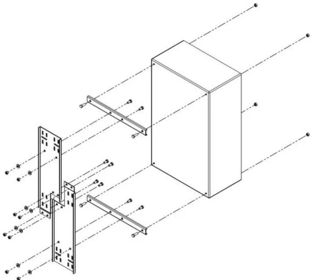
natural_image
Technical line drawing of a structural assembly with beams and supports, no text or symbols presentMounting Hardware
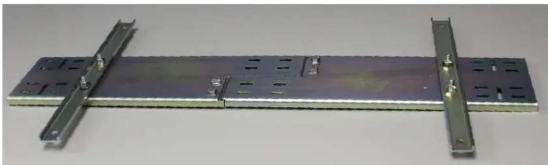
natural_image
Metallic electronic component with two metal brackets and mounting holes, no visible text or symbols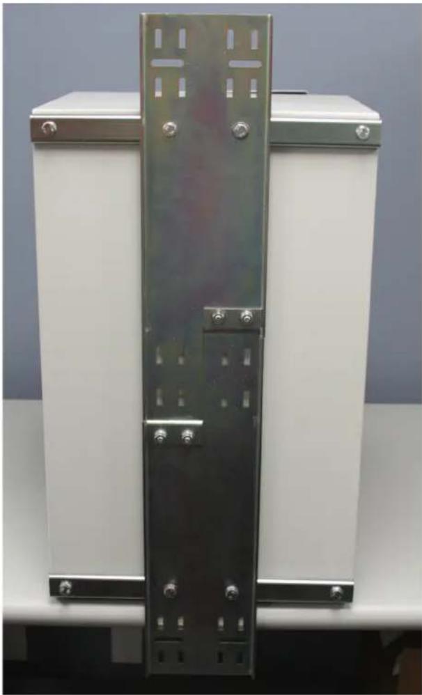
natural_image
Exterior view of a metallic industrial cabinet with mounting flanges and bolts (no text or symbols visible)Preparing the Enclosure
Attach grounding wire to the door and enclosure.
Remove plastic covers on copper studs. Add grounding cable to the two studs and use the copper washers and nuts to secure.
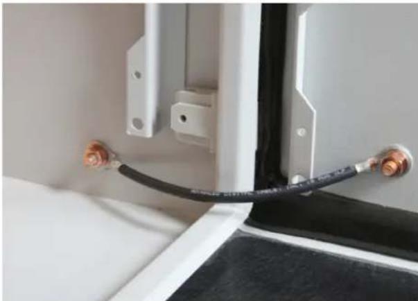
natural_image
Close-up of a white industrial panel with two metallic connectors and a black cable, no visible text or symbols.Grounding Cable Installed
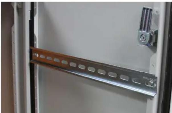
Mount the DIN Rail. The DIN Rail can be mounted to the door, backplate or sides of the enclosure.
natural_image
Close-up of a metallic electrical panel with a wooden strip and mounting bracket (no visible text or symbols)DIN Rail installed on door
Attached the DIN Rail Adapters to the Controller and Power Injector then clip to the DIN Rail.
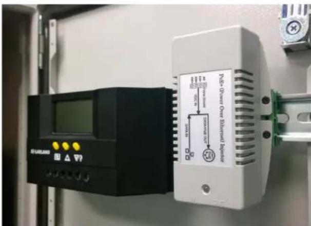
Controller and Power Injector Mounted on DIN Rail
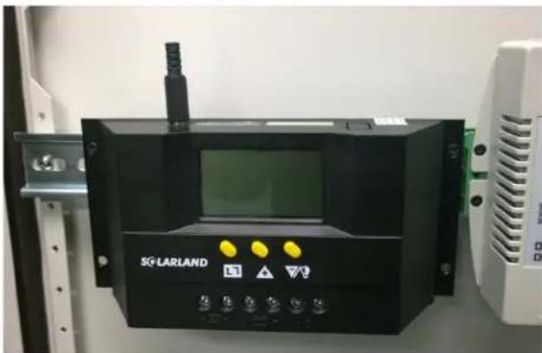
Plug the external thermal sensor into the interface of the thermal-sensor on the left of the controller.
natural_image
Black industrial control panel with display and indicator lights, no visible text or symbols on the device itself.Thermal Sensor Plugged into Controller
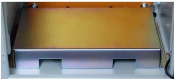
Insert battery platform in the enclosure. The cutouts in the platform are for routing cable under the batteries.
natural_image
Interior view of a white industrial machine with a yellow insulation panel and two recessed slots (no visible text or symbols)Battery Platform on Floor of Enclosure
Pole Mount
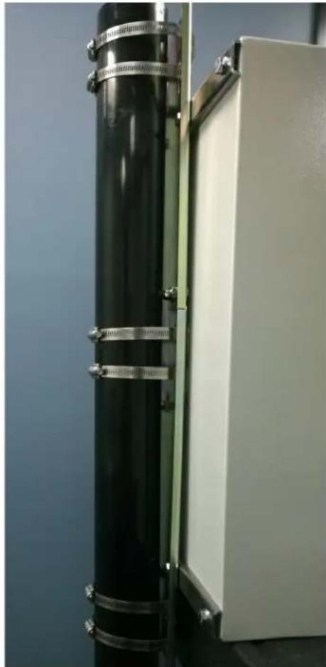
If mounting to a pole, use the 6 included Stainless Hose clamps to secure the enclosure to a pole. For your safety, we highly recommend mounting the enclosure before installing the batteries.
natural_image
Exterior view of a black cylindrical device mounted on an open white panel, with metal clamps attached (no visible text or symbols)Enclosure Mounted to Pole with Clamps
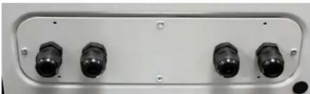
Add the cable glands and drain plug to the bottom of the enclosure after mounting.
natural_image
Front panel of an electronic device showing four black connectors (no visible text or symbols)Battery Platform on Floor of Enclosure
Solar Panel Electrical Wiring
Assemble The Solar Panels and run cable thru the cable glands on the bottom of the enclosure.
Do not connect PV cables to the controller yet, it is recommended to connect the battery first.
Enclosure Mounted to Pole with Clamps
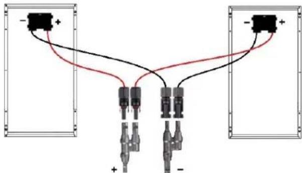
The NWKSP2 Kit Panels will need to be configured in parallel using the MMF (MaleMale to Female) and FFM (FemaleFemale to Male) MC4 Connectors.
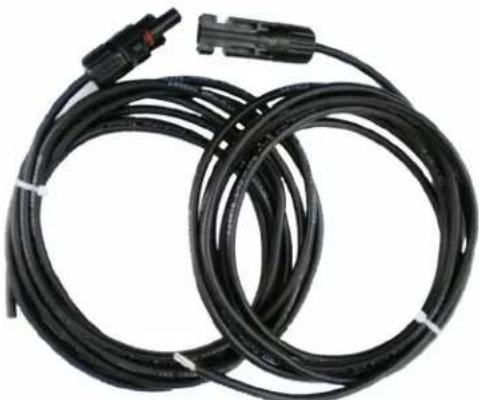
Connect the MC4 Male (Positive) Connectors from the solar panels to the MMF Connector then connect the 15' Cable with MC4 Female Connector to the Male FFM Connector and run cable thru a cable gland of the enclosure.
Connect the MC4 Female (Negative) Connectors from the solar panels to the FFM Connector then connect the 15' Cable with MC4 Male Connector to the Female MMF Connector and run cable thru a cable gland on the enclosure.
Note: The cables may ship as one 30' cable. If this is the case, you will need to cut the cable in half creating two 15' cables.
Please reapply the Twist Nut to the open end of the cables to prevent a short.
natural_image
Coiled black cable with connectors and a connector pin, no visible text or symbols15' MC4 Male and MC4 Female Cables
Battery Installation
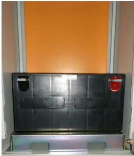
Insert battery into the enclosure. The battery can be installed vertically or horizontally.
We recommend installing on its side for ease of access.
natural_image
Black rectangular panel with multiple compartments and a red warning label, mounted on a white shelf against an orange wall (no text or symbols visible)Enclosure Mounted to Pole with Clamps
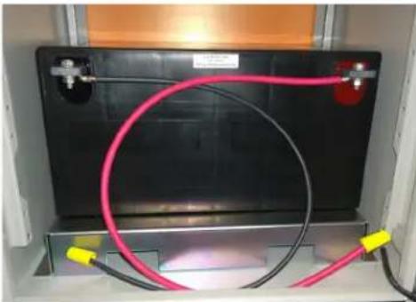
Connect the 24" 10AWG cables to the positive and negative battery posts.
natural_image
Close-up of a black rectangular electronic device with two red and yellow wires wrapped around it, mounted in a transparent enclosure (no visible text or symbols)PV Cable Connecting Battery Terminals
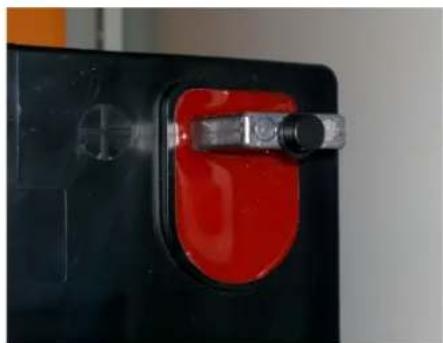
NOTE: Please apply rubber insulator to the terminals to prevent contact with the door in case of earthquake or vibration.
natural_image
Close-up of a black battery with a red switch and metallic clip (no visible text or symbols)Rubber Insulator
Connect the Positive and Negative cables from the battery to the Controller battery terminals.
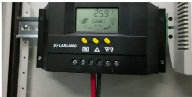
Battery Cables Connected to Controller Battery Terminals
Once batteries are connected to the controller, connect the PV cables from the solar panels to the Solar Load terminals on the controller.
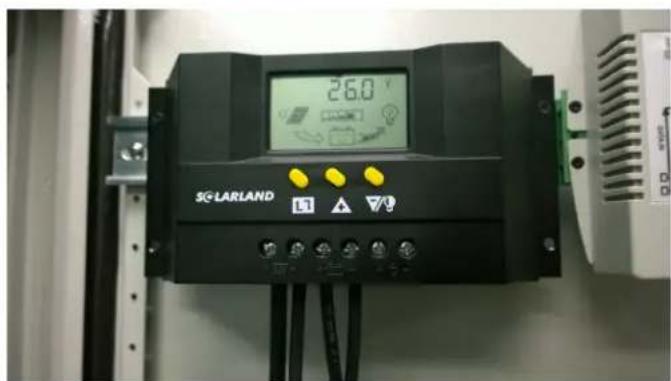
Solar Panel Cables Connected to Solar Load Terminals on Controller
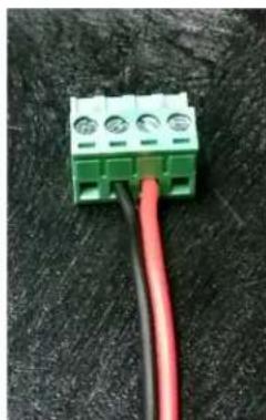
Connect the 12" Bonded Red and Black cable to the green terminal adaptor then connect the other end of the cable to the load terminals on the controller.
natural_image
Close-up of a green terminal block with three pins and two red wires, placed on a dark textured surface (no text or symbols visible)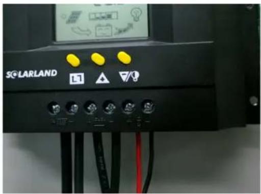
Red and Black Cable Connected Green Terminal Connector, left, and to Load Terminals on Controller, right.
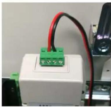
Insert green terminal into the Power Injector.
natural_image
Close-up of a white electronic device with green terminal blocks and red wires, no visible text or symbolsGreen Terminal Connector attached to Power Injector
See Solar Charge Controller User Manual for instructions on how to use the controller. Solar Panel mounting instructions will be included with the mounting hardware.
Agency Compliance
FCC
Changes or modifications not expressly approved by the party responsible for compliance could void the user's authority to operate the equipment. This device complies with Part 15 of the FCC Rules. Operation is subject to the following two conditions:
- This device may not cause harmful interference, and
- This device must accept any interference received, including interference that may cause undesired operation.
This equipment has been tested and found to comply with the limits for a Class A digital device, pursuant to part 15 of the FCC Rules. These limits are designed to provide reasonable protection against harmful interference when the equipment is operated in a Industrial environment. This equipment generates, uses, and can radiate radio frequency energy and, if not installed and used in accordance with the instruction manual, may cause harmful interference to radio communications. Operations of this equipment in a residential area is likely to cause harmful interference in which case the user will be required to correct the interference at his own expense.
Industry Canada
This Class A digital apparatus complies with Canadian ICES-003. To reduce potential radio interference to other users, the antenna type and its gain should be so chosen that the equivalent isotropically radiated power (EIRP) is not more than that permitted for successful communication. This device complies with Industry Canada license-exempt RSS standard(s).
Operation is subject to the following two conditions:
- This device may not cause interference, and
- This device must accept any interference, including interference that may cause undesired operation of the device.
The antennas used for this transmitter must be installed to provide a separation distance of at least 2.52m from all persons and must not be located or operating in conjunction with any other antenna or transmitter.
CE marking on this product represents the product is in compliance with all directives that are applicable to it.
This equipment may be operated in the following countries:
Great Britain and Northern Ireland, Austria, Belgium, Denmark, Finland, France, Germany, Ireland, Italy, Netherlands, Norway, Portugal, Romania, Switzerland, Sweden
Installer Compliance Responsibility
Devices must be professionally installed and it is the professional installer's responsibility to make sure the device is operated within local country regulatory requirements.
RoHS/WEEE Compliance Statement
European Directive 2002/96/EC requires that the equipment bearing this symbol on the product and/or its packaging must not be disposed of with unsorted municipal waste. The symbol indicates that this product should be disposed of separately from regular household waste streams. It is your responsibility to dispose of this and other electric and electronic equipment via designated collection facilities appointed by the government or local authorities. Correct disposal and recycling will help prevent potential negative consequences to the environment and human health. For more detailed information about the disposal of your old equipment, please contact your local authorities, waste disposal service, or the shop where you purchased the product.
GPL (General Public License) Statement
You may have received from ComNet products that contained - in part - free software (software licensed in a way that ensures your freedom to run, copy, distribute, study, change and improve the software). Such products include NetWave series of products.
As part of these products, ComNet may have distributed to you hardware and/or software that contained a version of free software programs developed by the Free Software Foundation, a separate not-for-profit organization without any affiliation to ComNet.
See http://www.gnu.org/philosophy/free-sw.html for more details. If ComNet distributed any portions of these free software programs to you, you were granted a license to that software under the terms of either the GNU General Public License or GNU Lesser General Public License "License", copies of which are available from http://www.gnu.org/licenses/licenses.html. The Licenses allow you to freely copy, modify and redistribute that software without any other statement or documentation from us.
ComNet will provide to anyone who contacts us at the contact provided below, for a charge of no more than our cost of physically performing source code distribution, a complete machine-readable copy of the complete corresponding source code for the free software programs used in the version of the programs that we distribute to you. The cost will be free if the delivery medium of the machine-readable copy is through the Internet.
Contact information:
Email: techsupport@comnet.net
Tel: 203-796-5300
Address: 3 Corporate Drive, Danbury, CT 06810 USA
We will reply within 7 working days once the request has been made through email or telephone.
ComNet Customer Service
Customer Care is ComNet Technology's global service center, where our professional staff is ready to answer your questions at any time.
Email ComNet Global Service Center: customercare@comnet.net
Contact Information
ComNet - www.comnet.net
| North America | ComNet Corporate Headquarters and Customer Support Center | Tel: +1-203 -796 -530 0Tel: +1-888-6789427Email: info@comnet.net |
| EMEA, PACRIM, South America | ComNet Europe Ltd, Leeds | Tel: +44 (0)113 307 6400Tel: +44 (0)113 307 6409Email: info-europe@comnet.net |
- INSTALLATION AND OPERATION MANUAL
- netwave®
- NWKSP2
- COMNET SOLAR POWERED SYSTEM
- About This Guide
- Related Documentation
- Website
- Support
- Safety
- Contents
- Overview
- Legal Information
- Copyright
- Disclaimer
- Introduction
- Pole Mounting Bracket Assembly
- Preparing the Enclosure
- Pole Mount
- Solar Panel Electrical Wiring
- Battery Installation
- Agency Compliance
- FCC
- Industry Canada
- Installer Compliance Responsibility
- RoHS/WEEE Compliance Statement
- GPL (General Public License) Statement
- ComNet Customer Service
- Contact Information
Brand : ComNet
Model : NWKSP2
Category : Solar panels