SRD-SPL-4 - Switch Crestron - Free user manual and instructions
Find the device manual for free SRD-SPL-4 Crestron in PDF.

User questions about SRD-SPL-4 Crestron
0 question about this device. Answer the ones you know or ask your own.
Ask a new question about this device
Download the instructions for your Switch in PDF format for free! Find your manual SRD-SPL-4 - Crestron and take your electronic device back in hand. On this page are published all the documents necessary for the use of your device. SRD-SPL-4 by Crestron.
USER MANUAL SRD-SPL-4 Crestron
Four-Way Amplified Splitter
Installation Guide
This document was prepared and written by the Technical Documentation department at:

CRESTRON®
Crestron Electronics, Inc.
15 Volvo Drive
Rockleigh, NJ 07647
1-888-CRESTRON
Contents
Four-Way Amplified Splitter: SRD-SPL-4 1
Introduction....1
Block Diagram....2
Specifications....2
Included Items ....3
Installation 4
Problem Solving....5
Troubleshooting....5
Further Inquiries....6
Future Updates....6
Return and Warranty Policies....7
Merchandise Returns / Repair Service....7
CRESTRON Limited Warranty....7
Four-Way Amplified Splitter: SRD-SPL-4
Introduction
The SRD-SPL-4 is a high quality amplified splitter optimized to split a single antenna signal to feed up to four satellite radio tuners as part of a Crestron ^® XM or SIRIUS ^® satellite radio distribution network. Its built-in line amplifier is rated to provide 8 dB (minimum) of gain in the satellite radio band (2320-2345 MHz), and is powered from the DC bias voltage (4.5 VDC to 6.5 VDC nominal) provided by the antenna connections on any of the satellite radio tuners downstream. It is also designed to pass DC voltage to provide power to the antenna and other line amplifiers installed upstream.
Accessories furnished with the SRD-SPL-4 include four 3-foot F (female)-to-SMB (male) adapter cables, four F (male)-to-F (male) couplers, and one SMB (female)-to-F (male) adapter. Standard RG-6 cable with male F connectors (not supplied) may be used to extend the output cable length up to 70 feet from each individual output to each satellite radio tuner. Adding an SRD-AMP-1 line amplifier (sold separately) at the input of the splitter will enable longer output cable lengths of up to 200 feet each.
NOTE: Unused outputs do not have to be terminated for proper operation.
A 20 dB power passing attenuator is also included for use in preventing overload of the splitter input in any installation that is located near a high power satellite radio terrestrial repeater.
NOTE: The SRD-SPL-4 is designed for indoor or outdoor mounting.
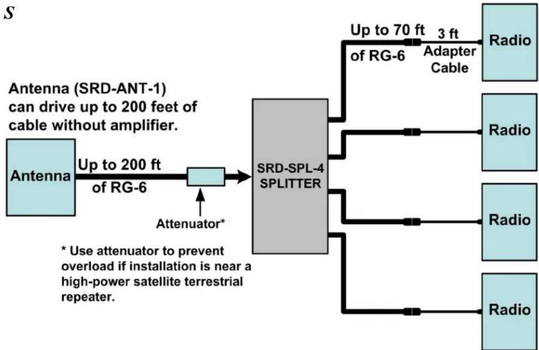
Block Diagram
The following diagram illustrates a typical application using the SRD-SPL-4 splitter.
flowchart
graph LR
    A["Antenna"] -->|Up to 200 ft of RG-6| B((SRD-SPL-4 SPLITTER))
    B --> C["RSD-ANT-1 can drive up to 200 feet of cable without amplifier."]
    B --> D["Attenuator*"]
    D --> B
    C --> E["Radio"]
    C --> F["Radio"]
    C --> G["Radio"]
    C --> H["Radio"]
    C --> I["Radio"]
    style A fill:#e6f3ff,stroke:#333
    style B fill:#cccccc,stroke:#333
    style C fill:#ffffff,stroke:#333
    style D fill:#ffffff,stroke:#333
    style E fill:#ffffff,stroke:#333
    style F fill:#ffffff,stroke:#333
    style G fill:#ffffff,stroke:#333
    style H fill:#ffffff,stroke:#333
    style I fill:#ffffff,stroke:#333
Specifications
Following are specifications for the SRD-SPL-4.
SRD-SPL-4 Specifications
| SPECIFICATION | DETAILS |
| Splitter gain @ 2.335 GHz 8 | dB minimum |
| Max noise figure 3 dB | |
| Max input signal -10 dBm (with supplied 20 dB attenuator) | |
| Current consumption 40 – 100 milliamps | |
| DC power passing All ports diode protected | |
| DC voltage drop (output to input) | 0.5 VDC typical |
| Environmental temperature | -40° to 150°F (-40° to 66°C) |
(Continued on following page)
SRD-SPL-4 Specifications (Continued)
| SPECIFICATION | DETAILS |
| Humidity 0% to 98% RH | (non-condensing) |
| Overall dimensions: | |
| Height | 0.88 in (2.24 cm) |
| Width | 3.75 in (9.53 cm) |
| Depth | 2.82 in (7.17 cm) |
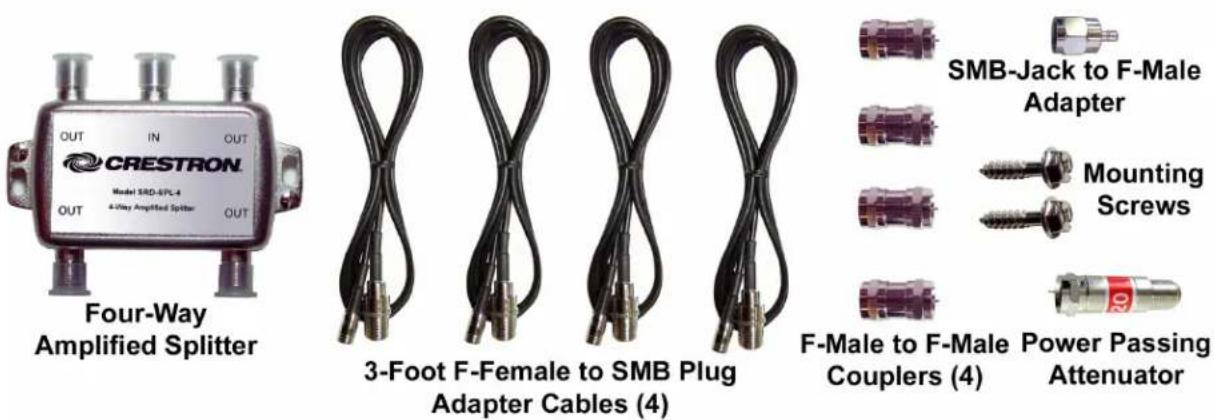
Included Items
The items included in the SRD-SPL-4 are listed and shown below.
SRD-SPL-4 Included Items
| DESCRIPTION | PART | NUMBER |
| 4-way Splitter with Mounting Screws SRD-SPL-4 1 | ||
| F-female to SMB-plug, 3 ft cables 2021515 4 | ||
| SMB-jack to F-male Adapter 2021579 1 | ||
| 20 dB Power Passing Attenuator 2021580 1 | ||
| F-male to F-male Coupler 2021526 4 |
Industry Compliance
As of the date of manufacture, the SRD-SPL-4 has been tested and found to comply with specifications for CE marking and standards per EMC and Radiocommunications Compliance Labelling.

Installation
Installation of the SRD-SPL-4 splitter consists of the following. Refer also to the “Block Diagram” on page 2.
- Attach the RG-6 cable from the antenna to the port labeled IN on the splitter.
- Attach RG-6 cables (up to 70 ft) to the splitter OUT ports and route them to the radios. Use the four supplied 3-foot cables to adapt the F-male connector on the RG-6 cables to the SMB-jacks on the radios.
NOTE: For best results in all configurations, use quad-shielded RG-6 cable whenever possible.
Problem Solving
Troubleshooting
The table after this paragraph provides corrective action for possible trouble situations. If further assistance is required, please contact a Crestron customer service representative.
SRD-SPL-4 Installation Troubleshooting
| TROUBLE | POSSIBLE CAUSES | CORRECTIVE ACTION |
| No signal reception. Radio display shows: “Antenna Disconnected”, or “Acquiring Signal” | Short circuits or discontinuities | With radio on and all antenna cables connected at the radio, check for 4 - 7 VDC at antenna end of cable. |
| With radios on and all antenna cables connected at the radios, check for AC voltage at antenna end of cable; should be < 1 VAC. If AC voltage is found, check for ground loops. | ||
| “Check Antenna” or “No Signal” | Antenna is connected properly but signal is too weak for reception. | Ensure proper cable type and length(s) per the block diagram on page 2. |
| Ensure any amplifiers are oriented properly with the output (marked with an arrow labeled Radio) oriented towards the radio. | ||
| Refer to the instructions supplied with the antenna to ensure the antenna is pointed accurately. | ||
| Limited reception or channels available for XM and/or SIRIUS tuners. | Problem with tuner card. | Ensure that the tuner card is registered/activated. |
Further Inquiries
If you cannot locate specific information or have questions after reviewing this guide, please take advantage of Crestron's award winning customer service team by calling Crestron at 1-888-CRESTRON [1-888-273-7876].
You can also log onto the online help section of the Crestron website (www.crestron.com/onlinehelp) to ask questions about Crestron products. First-time users will need to establish a user account to fully benefit from all available features.
Future Updates
As Crestron improves functions, adds new features and extends the capabilities of the SRD-SPL-4, additional information may be made available as manual updates. These updates are solely electronic and serve as intermediary supplements prior to the release of a complete technical documentation revision.
Check the Crestron website periodically for manual update availability and its relevance. Updates are identified as an “Addendum” in the Download column.
Return and Warranty Policies
Merchandise Returns / Repair Service
- No merchandise may be returned for credit, exchange or service without prior authorization from CRESTRON. To obtain warranty service for CRESTRON products, contact an authorized CRESTRON dealer. Only authorized CRESTRON dealers may contact the factory and request an RMA (Return Merchandise Authorization) number. Enclose a note specifying the nature of the problem, name and phone number of contact person, RMA number and return address.
- Products may be returned for credit, exchange or service with a CRESTRON Return Merchandise Authorization (RMA) number. Authorized returns must be shipped freight prepaid to CRESTRON, 6 Volvo Drive, Rockleigh, N.J. or its authorized subsidiaries, with RMA number clearly marked on the outside of all cartons. Shipments arriving freight collect or without an RMA number shall be subject to refusal. CRESTRON reserves the right in its sole and absolute discretion to charge a 15% restocking fee plus shipping costs on any products returned with an RMA.
- Return freight charges following repair of items under warranty shall be paid by CRESTRON, shipping by standard ground carrier. In the event repairs are found to be non-warranty, return freight costs shall be paid by the purchaser.
CRESTRON Limited Warranty
CRESTRON ELECTRONICS, Inc. warrants its products to be free from manufacturing defects in materials and workmanship under normal use for a period of three (3) years from the date of purchase from CRESTRON, with the following exceptions: disk drives and any other moving or rotating mechanical parts, pan/tilt heads and power supplies are covered for a period of one (1) year; touchscreen display and overlay components are covered for 90 days; batteries and incandescent lamps are not covered.
This warranty extends to products purchased directly from CRESTRON or an authorized CRESTRON dealer. Purchasers should inquire of the dealer regarding the nature and extent of the dealer's warranty, if any.
CRESTRON shall not be liable to honor the terms of this warranty if the product has been used in any application other than that for which it was intended or if it has been subjected to misuse, accidental damage, modification or improper installation procedures. Furthermore, this warranty does not cover any product that has had the serial number altered, defaced or removed.
This warranty shall be the sole and exclusive remedy to the original purchaser. In no event shall CRESTRON be liable for incidental or consequential damages of any kind (property or economic damages inclusive) arising from the sale or use of this equipment. CRESTRON is not liable for any claim made by a third party or made by the purchaser for a third party.
CRESTRON shall, at its option, repair or replace any product found defective, without charge for parts or labor. Repaired or replaced equipment and parts supplied under this warranty shall be covered only by the unexpired portion of the warranty.
Except as expressly set forth in this warranty, CRESTRON makes no other warranties, expressed or implied, nor authorizes any other party to offer any warranty, including any implied warranties of merchantability or fitness for a particular purpose. Any implied warranties that may be imposed by law are limited to the terms of this limited warranty. This warranty statement supersedes all previous warranties.
Trademark Information
All brand names, product names and trademarks are the sole property of their respective owners. Windows is a registered trademark of Microsoft Corporation. Windows95/98/Me/XP/Vista and WindowsNT/2000 are trademarks of Microsoft Corporation.

CRESTRON®
Crestron Electronics, Inc. Installation Guide - DOC. 6727A
15 Volvo Drive Rockleigh, NJ 07647
Tel: 888.CRESTRON
Fax: 201.767.7576 Specifications subject to
www.crestron.com change without notice.
(2021581)
08.08