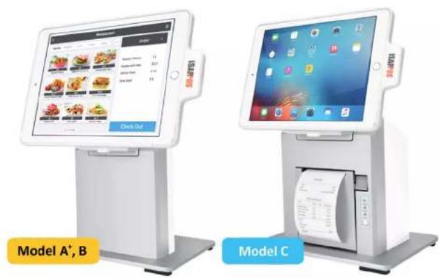
iSAPPOS 12C - Cash register POS-X - Free user manual and instructions
Find the device manual for free iSAPPOS 12C POS-X in PDF.

| Brand | POS-X |
| Model | iSAPPOS 12C |
| Product Type | iPad POS Stand with built-in printer (Model C) and cash drawer interface |
| Compatible iPad Sizes | 9.7-inch and 12.9-inch iPad (models A+, B, C) |
| Model Variants | A+ (basic), B (with COM ports, 5V/4A power), C (with printer, cash drawer, 19V/4.7A power) |
| Power Supply (Model C) | 19V DC, 4.7A (90W power adapter included) |
| Communication Interface | Bluetooth (for iPad connection), RJ-48 COM ports (2x for Model C), RJ-11 cash drawer port, Micro-USB for data syncing, USB for peripheral charging |
| Bluetooth | Bluetooth 4.0? (pairing LED blinks green), Pairing passcode: 2234 |
| Built-in Printer (Model C) | HPRT thermal printer (default), uses COM Port 3 |
| Supported External Printers | Star and Epson COM interface printers |
| Supported Scanners | Opticon COM interface scanners |
| Unlock Method | Touch ID (via iSATouch Unlock app) or manual override with paperclip |
| Material | Aluminum base plate and stand body |
| Package Contents (Model C) | Aluminum base plate, stand body, iPad jacket, 19V/4.7A power adapter, 2x RJ-48 cables, 1x RJ-11 cash drawer cable, 1x Micro-USB cable, screws, quick user guide |
| Safety Certifications | CE (EMC and LVD), FCC (Class B), WEEE (2012/19/EU) |
| Cleaning Instructions | Unplug power, use a moist cloth only; no liquid or aerosol cleaners |
| ESD Protection | Discharge static before touching components; use antistatic mats and wrist straps |
| Operating Environment | Indoor, dry location away from water and heat sources |
Frequently Asked Questions - iSAPPOS 12C POS-X
User questions about iSAPPOS 12C POS-X
0 question about this device. Answer the ones you know or ask your own.
Ask a new question about this device
Download the instructions for your Cash register in PDF format for free! Find your manual iSAPPOS 12C - POS-X and take your electronic device back in hand. On this page are published all the documents necessary for the use of your device. iSAPPOS 12C by POS-X.
USER MANUAL iSAPPOS 12C POS-X
User's Manual (Model A+/B/C)
iSAPPOS 9/12 Stand
iSAPPOS
Getting ready with the stand
1
Package Contents
System Overview
Getting Started
Package Contents
Model A+
- Aluminum base plate
• Aluminum Stand body - Jacket for iPad ^1
- 1 x Micro-USB cable (for power in)
- 2 x Screws for the Stand jacket
- 4 x thumb screws for the Stand base plate
- 2 x coin screws for the rear cover
- Quick user guide
Model B
- Aluminum base plate
• Aluminum Stand body - Jacket for iPad
- 5V/4A 20W power adapter
- 3 x RJ-48 COM port cables
- 1 x Micro-USB cable (for data-syncing)
- 2 x Screws for the Stand jacket
- 4 x thumb screws for the Stand base plate
- 2 x coin screws for the rear cover
- Quick user guide
Model C
- Aluminum base plate
• Aluminum Stand body - Jacket for iPad
• 19V/4.7A 90W power adapter - 2 x RJ-48 COM port cables
- 1 x RJ-11 cable for cash drawer
- 1 x Micro-USB cable (for data-syncing)
- 2 x Screws for the Stand jacket
- 4 x thumb screws for the Stand base plate
- 2 x coin screws for the rear cover
- Quick user guide
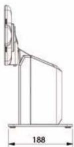
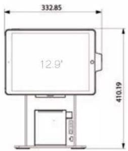
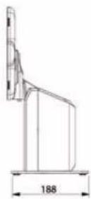
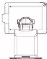
System Overview
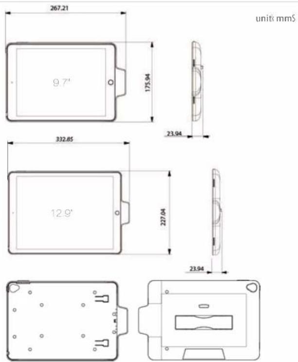
The Jacket
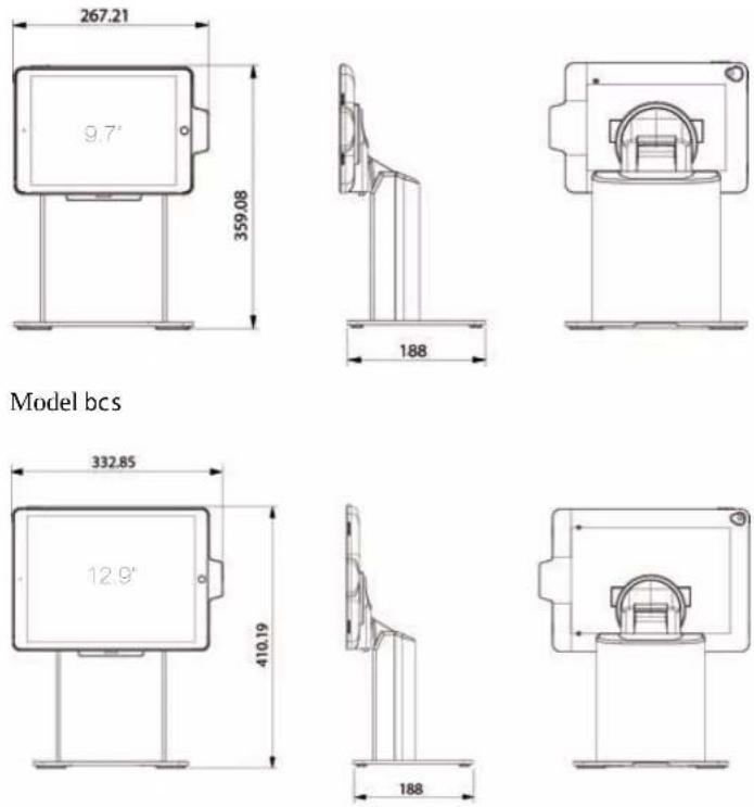
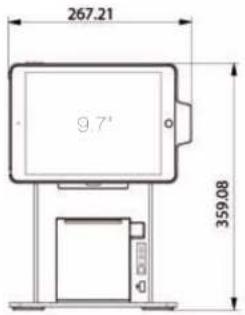
The Stand
Model jr js
unit: mms
Model j t
natural_image
Technical line drawing of a mechanical component with dimension标注 (no text or symbols)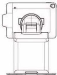
natural_image
Technical line drawing of a mechanical device with no visible text or symbolsModel bct
natural_image
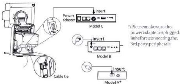
Technical line drawing of a mechanical device with no visible text or symbolsI/O Ports
Model r
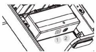
natural_image
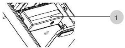
Diagram of a vehicle interior showing a mounted device with labeled buttons (1 and 2), no readable text or symbols present.1 Powerconnector
2 Bluetooth/Painbutton
Models
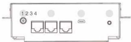
natural_image
Front view of a network device with three Ethernet ports and indicator lights (no text or symbols visible)1 Powerconnector
2 RJ-48itouCOMports
3 Micro-USBiport(iPaddataasyncing)
4 Bluetooth:Pairbutton
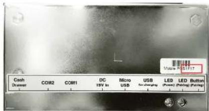
Model t
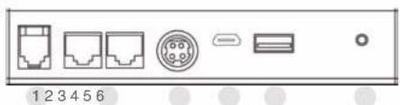
1 RJ-11: cashidrawenport
2 RJ-48uto.COMports
3 Powerconnector
4 Micro-USBport(iPaddataSyncing)
5 USBport(peripheralcharging)
6 Bluetooth/Painbutton
LEDs
Model r
natural_image
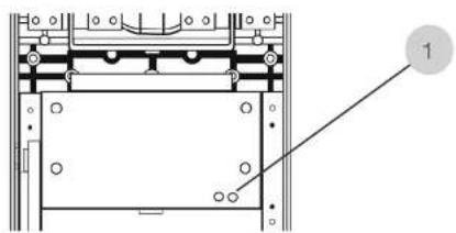
Technical line drawing of a mechanical component with no visible text or symbolsPairing LED:
Blinking green: Stand
Bluetooth pairing mode on
rear view of the Stand with rear plastic cover removed\$
Model s t
natural_image
Technical diagram of a mechanical assembly with no visible text or symbolsPairing LED:
Blinking green: Stand
Bluetooth pairing mode on
rear view of the Stand with rear plastic cover removed
Model t
flowchart
graph TD
    A["Device Panel"] --> B["Power"]
    A --> C["Resistor"]
    A --> D["Ground"]
    B --> E["1"]
    C --> F["2"]
    D --> G["3"]
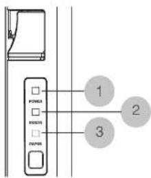
1
Power LED:
Solid green System on
Off: System off
2
Error LED:
Solid red System error
Off: System normal
3
Paper LED:
Solid green Printer normal
Solid red: printer error
Getting started
Getting started
Assemble iPad and the Stand
• Tools needed Phillips \$ Ma Screwdriver

• r ssemble the stand
b' Secure the base plate and Stand body with Me thumb screws xeS found in the accessory box
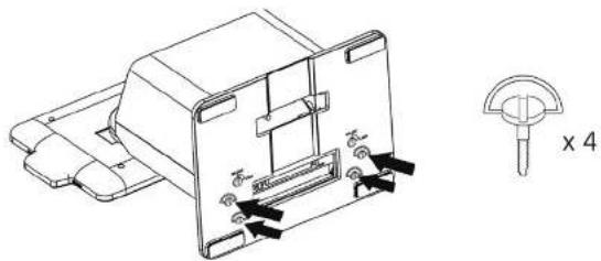
natural_image
Technical line drawing of a mechanical component with mounting holes and a cross-sectional view (no text or symbols)c't onnect the power adapter for charging
d' Place the back cover to the back of the stand' Secure the back cover and the base plate using the coin screws xCS found in the accessory box' Tighten them with a coin'
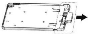
- Insert the iPad to the jacket
→ Slide open the jacket
natural_image
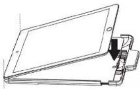
Technical line drawing of a rectangular electronic device with mounting holes and internal components (no text or symbols)→ Insert and align iPad with the jacket (It's normal to see the side with the home bottom is higher than the other side)
natural_image
Line drawing of a flat electronic device with a clamped arm attachment (no text or symbols)→ Slide close the jacket gently and slowly. While sliding close the jacket, press down both corners of the iPad like indicated in the picture and make sure it's aligned with the jacket.
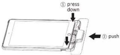
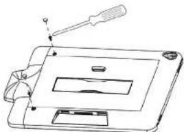
→ Remove the paddings of the indicated screw holes. Secure the iPad and the jacket with Phillips(+) #0 Screwdriver and M2 screws (x2) found in the accessory box. Place the paddings to cover the indicated screw holes.
natural_image
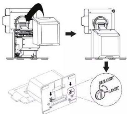
Technical line drawing of a mechanical device with a screwdriver and handle (no text or symbols)- Place the jacket onto the Stand's dock. (make sure the lock-unlock switch is in the unlock position)
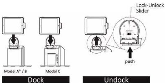
* Undock: Push the button at the bottom of the cradle and lift up the jacket to detach it from the Stand.
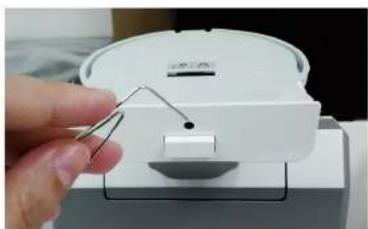
Unlock Jacket from the Stand Manually
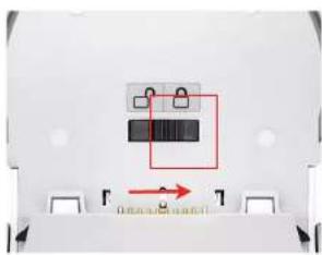
If the jacket is placed on the Stand while the Lock-Unlock slider on the cradle is in "Lock" position, you can manually override the switch and unlock the jacket from the Stand by using a paperclip and push up the button hidden at the bottom of the cradle. Lift up the jacket while the button is pushed up to detach it from the Stand.
natural_image
Close-up of a mechanical component with a red annotation arrow and label 'On/Off' (no readable text or symbols)When locked Override
natural_image
Close-up of a hand holding a white plastic device with a clip, mounted on a stand (no visible text or symbols)mechanism to unlock
Install app
App Store Search:


iSATouch Unlock (For FingerPrint Unlock) Model A+/B/C
https://itunes.apple.com/us/app/isatouch-unlock/id1225916845?mt=8


SteakHouse POS (For Demo) Model B/C
https://itunes.apple.com/us/app/isappos-steakhouse-pos/id1233529859?mt=8
* The SteakHouse app is only an app to demonstrate the functions of the Stand. It is not suitable to be used in the real business environment.
Running and using the app
2
Turn on Bluetooth
iSATouch Unlock App
SteakHouse App
Turn on Bluetooth
Pairing with the Stand sForModelA +,BlandConly)
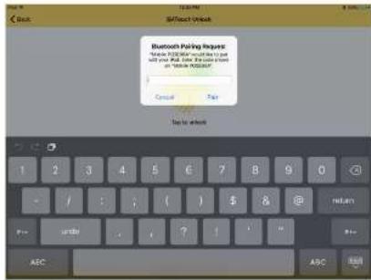
The app will essentially help you set up the Stand with your iPad? r s the Stand communicates with your iPad through s bluetooth please make sure s bluetooth is enabled on your iPad by before launching the app? You can enable s bluetooth by going to S Settings → > Bluetooth.
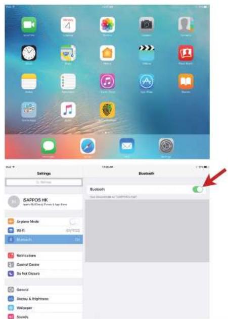
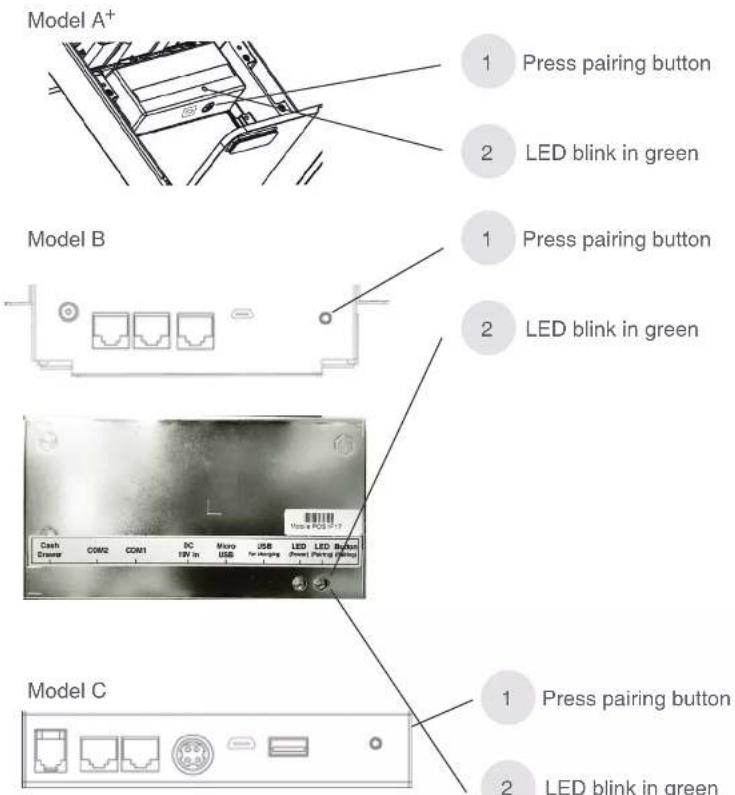
rfter you have s bluetooth enabled remove the back cover from the Stand and locate the pair button in the back! Press the button to initiate bluetooth connection between the Stand and your iPad! The Pairing Lvu should start blinking!
iSATouch Unlock App
About the app
The app provides a simple function that allows you to connect to your stand and unlock the jacket from it by using r pple's Touchlu'i
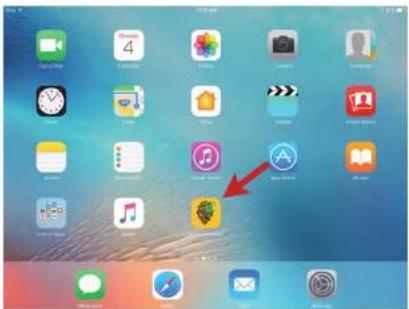
Launching the app sFor Model A ^W / B / C onlyt
rfter the app is downloaded and installed you should be able to locate it on the home screen ^4 Simply tap on it to launch the app ^4
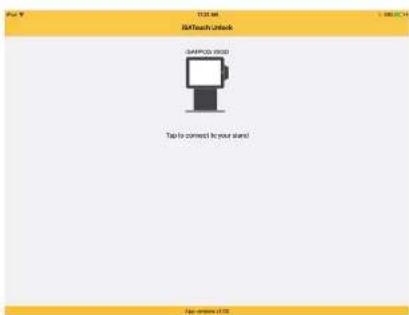
Connect the Stand
Opening the app will start scanning a nearby Stand immediately' Push the pair button in the back of the Stand will start broadcasting itself to the app
Once the Stand is found it will be displayed like shown in the screenshot below! Simply tap the icon to connect to the stand!
plffyourStandfis/notfoundnfufheappcheckthepairing!LEDfinthebackfofftheStandfandfmakesurefitisblinkinghinfpairinghindexflffnoofpresslthefpairbuttonnfotstartpairingagain.
plff/yourhavefmultiple*Standsnearby#yourcanteasilyflocatethe*StandfyourwouldhlikeofconnectflylookingupftheflastfourdigitofftheMACaddressfatisfactiontheLabelfinthebackfoyour*StandfMarchthose numberswiththefonefshownintheapps
When you pair your iPad with the Stand for the first time, you will be prompted to enter passcode, simply enter "2234" and tap "Pair" to finish the pairing process.
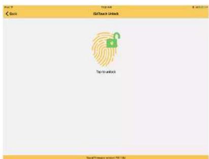
Once you are successfully connected to the Stand, you should be directed to another page of the app where you can access the unlock function.
* If a previously connected Stand is disconnected due to reasons such as out of range or powered off, the icon will be displayed in a semi-transparent color illustrating an inaccessible Stand.
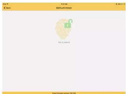
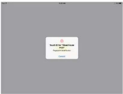
Tapping the icon will unlock the jacket from the Stand through Apple's TouchID function in your iPad. The jacket should be unlocked once the fingerprint matches the one you set up in your iPad.
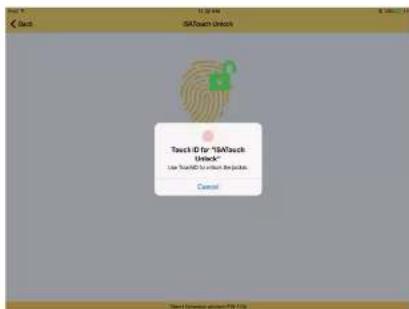
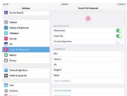
* In order for this function to work, please first set up fingerprint for the TouchID function in your iPad by going to Settings > Touch ID & Passcode
You will have a 10 second window to remove the jacket from the stand before it is locked again. During this period of time, the unlock button will be disabled.
Using iOS Today's Widget to unlock the jacket
After the app is installed, it also installs an app widget which can be accessed from iOS Today's Widget menu. The advantage of providing an app widget is that the unlock function can be easily accessed anytime with a swipe down on the screen regardless what app you are currently using.
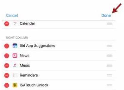
To enable the widget, pull down anywhere from the top of the iPad screen to access Today's Widget menu.
You will need to enable the app widget first. To do so, tap on the "Edit" button to add the app widget to the menu.
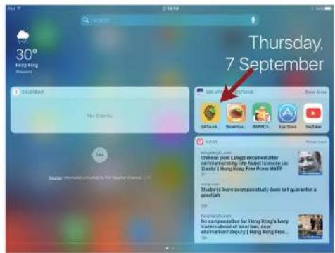
You should see the iSATouch Unlock app widget from the list menu like shown below. Tap on the green "+" button to add it to the Today's widget menu.

Tap "Done" to finish.
You can now access the app widget in iOS Today's Widget menu. Tapping on the icon will allow you to unlock the jacket without leaving or closing the app you are currently using.
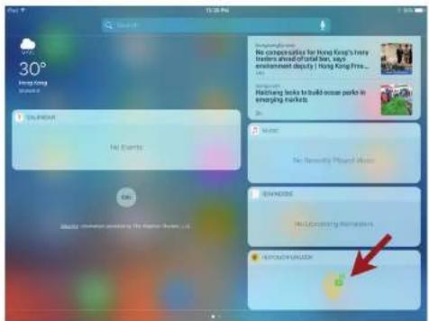
*If your Stand is disconnected when you are unlocking the jacket from the Today's Widget menu, the iSATouch Unlock main app will be launched instead so you can pair with the Stand again.
Section 3
SteakHouse App
About the app
The app provides users the ability to connect and configure the Stand as well as accessing its hardware functions in a form of a simple POS (Point of Sales) app.
Launching the app (For Model B and C only)
After the app is downloaded and installed, you should be able to locate it on the home screen. Simply tap on it to launch the app.

Log in the app
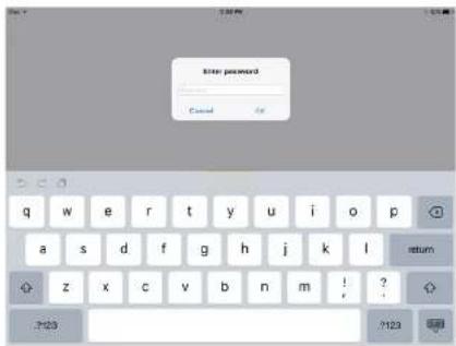
You will be prompted to log in after the app is launched.
If you have TouchID configured on your iPad, simply log in with TouchID.
If TouchID is not yet configured, tap on the "Enter Password" option to log in by entering the password manually.

When prompted, enter the password "1234" to log in.
Connect the Stand
To connect the Stand with the app, tap on "BLE Config" in the lower-left hand corner of the app.

other
| Item | Price ($) | | :--- | :--- | | 1. Tacos Steak | 22.00 | | 2. Chicken | 22.00 | | 3. Salmon | 26.00 | | 4. Pumpkin Soup | 8.00 | Total: $78.90 Nut Chops | | Pie Chart | | Fruit Only Disconnected | | Cream Only | | Milk Only | | Chicken Only | | Fish and Beans | | Mushroom Soup | | Fruit | | Sweet Fruit |The app will start searching for Stands nearby. Press the "Pair" button in the back of the Stand for the one you wish to connect with the app. Tap on the one from the list to connect to the Stand.

* If it is pairing for the first time, please enter the password "2234" to connect to the Stand.
If you have more than one Stands powered on nearby, use the ID number from the back of the Stand (with rear plastic cover removed) and match it with the one from the list shown in the previous step to make sure you are connecting to the desired Stands.
Once connected, you will be directed back to the main page upon a successful connection. The connection status with the Stand should now be "Connected" in the lower-left hand corner of the app.

Configuring the COM ports for peripherals
There are three COM ports in the model B and two COM ports in the model C in which you can connect compatible peripherals to.
Change settings in the "COM Config" page according to the peripheral that is connected to the Stand through the COM interface.

* Do not change settings on Printer Port 3 when using the app with a model C Stand. The built-in printer in model C is designed to use port 3 at all time.
* To change value of any field, tap on the blue text in that field to do so.
- You shouldn't need to change any settings when using a compatible peripheral. Simply connect the peripheral to the Stand and make sure the Stand is connected to the app.
Connect and configure compatible printer
You can connect an external compatible printer through the COM port in the Stand. Change the "Printer Model" in the "COM Config" page that matches the one that is connected to the Stand.

* HPRT is the default printer model as it is the one that is built into the model C Stand.
- You can alternatively change it 'Auto detect' for easier configuration when connecting to an external printer.
* The Stand supports COM interface printer from Star as well as Epson (only the models listed in the above screenshots).
Connect and configure compatible scanner
The Stand supports COM interface scanner from Opticon. Be sure to select the correct port number based on which port the scanner is being connected to.
For any changes to take effect, tap "Set" first and tap "Save" to save the new settings.

^2 Should you have interest to purchase Opticon scanners, please contact us at isappos@isappos.com
Print receipts with the app
To print receipts with the app, add items from the menu first. Added items should be shown in the list on the left.
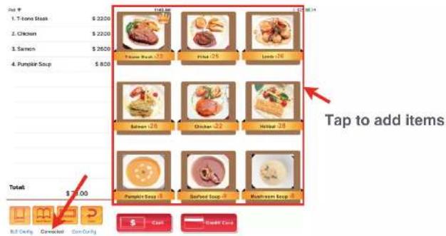
Tap on the "Cash" button should print out the receipt with items added.
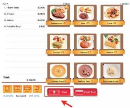
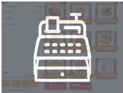
Below screen will be shown after tapping on the "Cash" button. It means the transaction has been completed and it would go back to the main menu automatically.
Unlock the jacket from the Stand
If the jacket is placed and locked on the Stand, you can unlock the jacket by using the "Undock" function in the app.

You will be prompted for authentication using the TouchID to unlock the jacket.

The Stand only connects to one app at a time
Please note the Stand can only remain connection with one app at a time. The last app that Stand connects to will disconnect the Stand from the previously connected app.
Regulatory Information
3
Regulatory Information
Safety Caution
Legislation and WEEE Symbol
Safety Instruction
Environmental
Regulatory Information
Caution
Always connect the Micro USB Cable to the power adapter before inserting to the power outlet.
CE CE MARK
This device complies with the requirements of the EEC directive 2004/108/EC with regard to "Electromagnetic compatibility" and 2006/95/EC "Low Voltage Directive".
FCC FCC Statement
This equipment has been tested and found to comply with the limits for a Class B digital device, pursuant to part 15 of the FCC Rules. These limits are designed to provide reasonable protection against harmful interference in a residential installation. This equipment generates, uses and can radiate radio frequency energy and, if not installed and used in accordance with the instructions, may cause harmful interference to radio communications. However, there is no guarantee that interference will not occur in a particular installation. If this equipment does cause harmful interference to radio or television reception, which can be determined by turning the equipment off and on, the user is encouraged to try to correct the interference by one or more of the following measures:
- Reorient or relocate the receiving antenna.
- Increase the separation between the equipment and receiver.
- Connect the equipment into an outlet on a
circuit different from that to which the receiver is connected.
- Consult the dealer or an experienced radio/TV technician for help.
The FCC ID of our product are as below:
FCC Radiation Exposure Statement
This device complies with FCC radiation exposure limits set forth for an uncontrolled environment. This device complies with Part 15 of the FCC Rules. Operation is subject to the following two conditions:
• This device may not cause harmful interference.
- This device must accept any interference received, including interference that may cause undesired operation.
Caution!
Any changes or modifications not expressly approved by the party responsible for compliance could void the user's authority to operate the equipment.
Safety Notice
Note: To comply with IEC60950-1 Clause 2.5 (limited power sources, L.P.S) related legislation, peripherals shall be 4.7.3.2 "Materials for fire enclosure" compliant.
4.7.3.2 Materials for fire enclosures
For MOVABLE EQUIPMENT having a total mass not exceeding 18kg. The material of a FIRE
ENCLOSURE, in the thinnest significant wall thickness used, shall be of V-1 CLASS MATERIAL or shall pass the test of Clause A.2.
For MOVABLE EQUIPMENT having a total mass exceeding 18kg and for all STATIONARY EQUIPMENT, the material of a FIRE ENCLOSURE, in the thinnest significant wall thickness used, shall be of 5VB CLASS MATERIAL or shall pass the test of Clause A.1.
Legislation and WEEE Symbol
2012/19/EU Wast Electrical and Electronic Equipment Directive on the treatment, collection, recycling and disposal of electric and electronic devices and their components.
The crossed dust bin symbol on the device mean that it should not be disposed of with other household wastes at the end of its working life. Instead, the device should be taken to the waste collection centers for activation of the treatment, collection, recycling and disposal procedure. To prevent possible harm to the environment or human health from uncontrolled waste disposal, please separate this from other types of wastes and recycle it responsibly to promote the sustainable reuse of material resources.
Household users should contact either the retailer where they purchased this product, or their local
government of CE, for details of where and how they can take this item for environmentally safe recycling.
Business users should contact their supplier and check the terms and conditions of the purchase contract.
This product should not be mixed with other commercial wastes for disposal.
Safety Instructions
Please adhere to the following safety guidelines to help ensure your own personal safety and protect your system from potential damage.
Any acts taken that are inconsistent with ordinary use of the product, including improper testing, etc., and those not expressly approved by iSAPPOS may result in the loss of product warranty.
Unless expressly approved by an authorized representative of iSAPPOS in writing, you may not and may not permit others to:
- Disassemble or reverse engineer the device or attempt to derive source code (underlying ideas, algorithms, or structure) from the device or from any other information provided by iSAPPOS, except to the extent that this restriction is expressly prohibited by local law.
- Modify or alter the device.
- Remove from the device any product identification or other notices, including copyright notices and patent markings, if any. To reduce the risk of bodily injury, electrical shock, fire, and damage to the device and other equipment, observe the following precautions:
Power Sources
- Observe and follow service markings.
- Do not push any objects into the openings of your device unless consistent with the authorized operation of the device. Doing so can cause a fire or an electrical shock by shorting out interior components.
- The powering of this device must adhere to the power specifications indicated for this product.
- Do not overload wall outlets and/or extension cords as this will increase the risk of fire or electrical shock.
- Do not rest anything on the power cord or on the device (unless the device is made and expressly approved as suitable for stacking).
- Position system cables and power cables carefully; route cables so that they cannot be stepped on or tripped over. Be sure that nothing rests on any cables.
- Operate the device only from the type of external power source indicated on the electrical ratings label.
- To help prevent an electrical shock, plug the device and peripheral power cables into properly grounded electrical outlets. These cables are equipped with three-prong plugs to help ensure proper grounding. Do not use adapter plugs or remove the grounding prong from a cable. If you must use an extension cable, use a 3-wire cable with properly grounded plugs.
- Observe extension cable and power strip ratings. Ensure that the total ampere rating of all products plugged into the extension cable or power strip does not exceed 80 percent of the ampere ratings limit for the extension
cable or power strip.
• To help protect your device from sudden, transient increases and decreases in electrical power, use a surge suppressor, line conditioner, or uninterruptible power supply (UPS).
- Do not modify power cables or plugs. Consult a licensed electrician or your power company for site modifications. Always follow your local/national wiring rules.
- When it is connecting or disconnecting power to hot-pluggable power supplies, if offered with your device, observe the following guidelines.
• Install the power supply before connecting the power cable to the power supply.
- Unplug the power cable before removing the power supply.
- If the system has multiple sources of power, disconnect power from the device by unplugging all power cables from the power supplies.
Servicing/Disassembling
- Do not service any product except as expressly set forth in your system documentation.
- Opening or removing covers that are marked with the triangular symbol with a lightning bolt may expose you to an electrical shock. Only a trained service technician should service components inside these compartments.
- To reduce the risk of electrical shock, never disassemble this device. None of its internal parts are userreplaceable; therefore, there is no reason to access the interior.
- Do not spill food or liquids on your system
components, and never operate the device in a wet environment. If the device gets wet, contact your trained service provider.
- Use the device only with approved equipment.
- Move products with care; ensure that all casters and/or stabilizers are firmly connected to the system. Avoid sudden stops and uneven surfaces.
Environment
- Do not use this device near water (e.g. near a bathtub, sink, laundry tub, in a wet basement or near a swimming pool) even in areas with high humidity. This device also must not be subjected to water or condensation.
- Keep your device away from radiators and heat sources.
Cleaning
• Always unplug the power before cleaning this device.
- Do not use liquid or aerosol cleaners of any kind.
- Use a moist cloth for cleaning.
Protecting Against Electrostatic Discharge Static electricity can harm delicate components inside your system. To prevent static damage, discharge static electricity from your body before you touch any of the electronic components, such as the microprocessor. You can do so by periodically touching an unpainted metal surface on the chassis. You can also take the following steps to help prevent damage from electrostatic discharge (ESD):
- When unpacking a static-sensitive component
from its shipping carton, do not remove the component from the antistatic packing material until you are ready to install the component in your system. Just before unwrapping the anti-static packaging, be sure to discharge static electricity from your body.
- When transporting a sensitive component, please first place it in an antistatic container or packaging.
- Please handle all sensitive components in a static-safe area. If possible, use antistatic floor pads, workbench pads, and an antistatic grounding strap.
ISAPPOS © COPYRIGHT 2017. ALL RIGHTS RESERVED.
Apple iPhone and iPad are registered trademarks of Apple, Inc. and are not included. They serve as a reference only and does not imply any affiliation with or endorsement by Apple.
UMA+BCOEN1109171
- User's Manual (Model A+/B/C)
- iSAPPOS 9/12 Stand
- Getting ready with the stand
- Package Contents
- Model A+
- Model B
- Model C
- System Overview
- The Stand
- I/O Ports
- LEDs
- Getting started
- Unlock Jacket from the Stand Manually
- Install app
- Running and using the app
- 2
- Turn on Bluetooth
- iSATouch Unlock App
- Connect the Stand
- Using iOS Today's Widget to unlock the jacket
- Section 3
- SteakHouse App
- About the app
- Log in the app
- Configuring the COM ports for peripherals
- Connect and configure compatible printer
- Connect and configure compatible scanner
- Print receipts with the app
- Unlock the jacket from the Stand
- The Stand only connects to one app at a time
- Regulatory Information
- 3
- Caution
- CE CE MARK
- FCC FCC Statement
- FCC Radiation Exposure Statement
- Caution!
- Safety Notice
- Legislation and WEEE Symbol
- Safety Instructions
- Power Sources
- Servicing/Disassembling
- Environment
- Cleaning
Brand : POS-X
Model : iSAPPOS 12C
Category : Cash register