Ever T45CD-P-DC-US - Chargeur pour appareil mobile Bretford - Free user manual and instructions
Find the device manual for free Ever T45CD-P-DC-US Bretford in PDF.

User questions about Ever T45CD-P-DC-US Bretford
0 question about this device. Answer the ones you know or ask your own.
Ask a new question about this device
Download the instructions for your Chargeur pour appareil mobile in PDF format for free! Find your manual Ever T45CD-P-DC-US - Bretford and take your electronic device back in hand. On this page are published all the documents necessary for the use of your device. Ever T45CD-P-DC-US by Bretford.
USER MANUAL Ever T45CD-P-DC-US Bretford
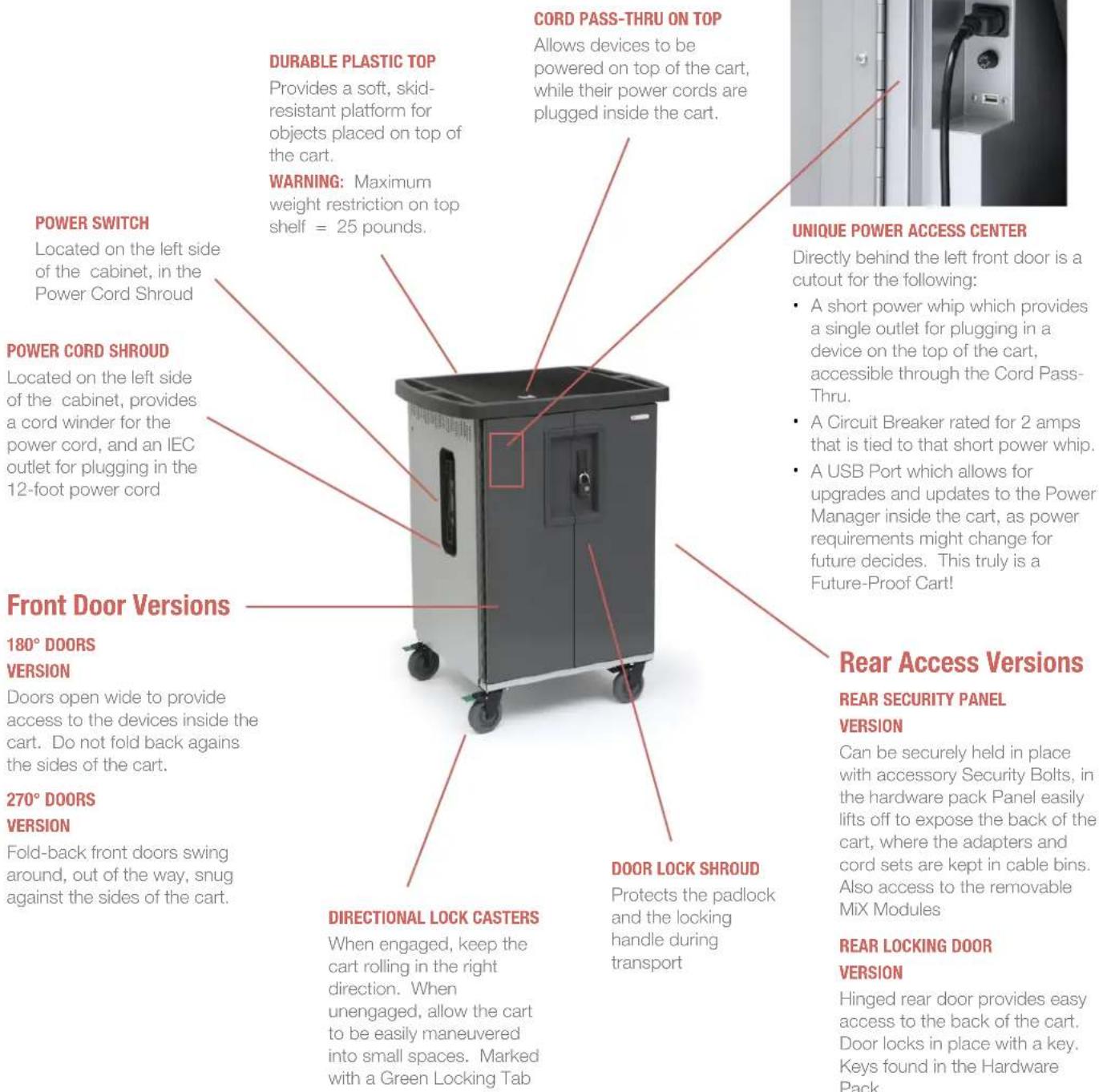
T30C-P-AC-US EVER Charging Cart AC for up to 30 devices w/180° front doors w/Back Panel T30CB-P-AC-US EVER Charging Cart AC for up to 30 devices w/180° front doors w/Rear Door T30CD-P-AC-US EVER Charging Cart AC for up to 30 devices w/270° front doors w/Back Panel T30CDB-P-AC-US EVER Charging Cart AC for up to 30 devices w/270° front doors w/Rear Door
T45C-P-AC-US EVER Charging Cart AC for up to 45 devices w/180° front doors w/Back Panel T45CB-P-AC-US EVER Charging Cart AC for up to 45 devices w/180° front doors w/Rear Door T45CD-P-AC-US EVER Charging Cart AC for up to 45 devices w/270° front doors w/Back Panel T45CDB-P-AC-US EVER Charging Cart AC for up to 45 devices w/270° front doors w/Rear Door
T30C-P-DC-US EVER Charging Cart USB for up to 30 devices w/180° front doors w/Back Panel T30CB-P-DC-US EVER Charging Cart USB for up to 30 devices w/180° front doors w/Rear Door T30CD-P-DC-US EVER Charging Cart USB for up to 30 devices w/270° front doors w/Back Panel T30CDB-P-DC-US EVER Charging Cart USB for up to 30 devices w/270° front doors w/Rear Door
T45C-P-DC-US EVER Charging Cart USB for up to 45 devices w/180° front doors w/Back Panel T45CB-P-DC-US EVER Charging Cart USB for up to 45 devices w/180° front doors w/Rear Door T45CD-P-DC-US EVER Charging Cart USB for up to 45 devices w/270° front doors w/Back Panel T45CDB-P-DC-US EVER Charging Cart USB for up to 45 devices w/270° front doors w/Rear Door
Technical Specifications
| CAPACITY per slot width | 1.00" | 1.25" | 1.50" | ||
| T30 Series | 2 modules | 30 | 24 | 20 | devices |
| T45 Series | 3 modules | 45 | 36 | 30 | devices |
COMPATIBILITY Designed for various sized laptops & chromebooks, yet versatile enough to support most tablets.
AC versions use the device manufacturer supplied AC power cord and adapter. DC versions provide USB ports for USB to Lightning or USB to Micro USB plugs
OUTSIDE DIMENSIONS 33.50"W x 26.00"D x 44.5"H
SLOT DIMENSIONS 1.00" or 1.25" or 1.50" W x 10.00"H or 12.00"H x 17"D
WEIGHT WITHOUT DEVICES T30 series 176 pounds T45 series 190 pounds
POWER MANAGER Digital
POWER REQUIREMENTS 100 -125V ac, 12A, 50/60Hz; 220-240Vac, 8A, 50/60Hz; optional USB output; 5Vdc, 2.4A
SHIPPING Ships fully assembled, ready to load devices
WARRANTY For product specific warranty information, please visit: bretford.com/warranty

MADE IN USA with globally sourced products


General Use
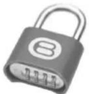
SETTING THE COMBINATION LOCK
Your new EVER Cart comes equipped with a resettable Combination Padlock. You can program the lock with your own combination. The lock starts with 0-0-0-0. Follow the directions with the look for changing the combination. Remember to depress the shackle before un-engaging it from the lock.
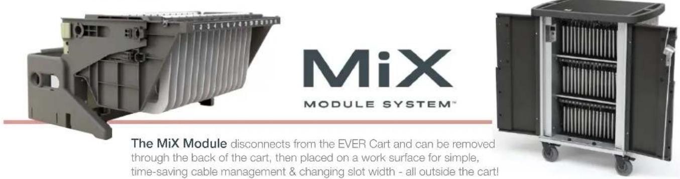
The MiX Module disconnects from the EVER Cart and can be removed through the back of the cart, then placed on a work surface for simple, time-saving cable management & changing slot width - all outside the cart!
Removing MiX Module from EVER Cart
- Remove the devices from the front of the cart and place in a safe location (very important)
- From the front of the cart, reach in under the MiX Module dividers and slide the Locking Tabs away from the cart's interior side wall ... both sides. This releases the MiX Module from the cart interior.
- Rear Security Panel Version: At the back of the cart, unscrew the two thumb screws. Lift the Back Panel off of the chassis. Rear Locking Door Version: Using the key from the hardware pack, unlock the back door and swing it open. This exposes the backs of the MiX Modules.
- Unplug the power cord and the cat 6 cable from the cart. This cat 6 cable is used for the Power Management System to communicate with each of the power strips in the cart. The MiX Module is now ready to be lifted out of the cart.
- Using the built-in handles, lift the MiX Module out of the cart and set it on a work surface. You are now ready to start customizing the slots for your specific devices and cable management.
REAR SECURITY PANEL VERSION
natural_image
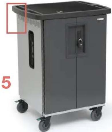
Exterior view of a gray industrial cart with wheels and a closed door (no visible text or symbols)- Unscrew the Thumb Screws - one on each side of the cart at the back. Lift off the Back Panel.
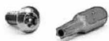
Security Screws
Your new EVER Cart comes equipped with 2 Security Screws and a Security Bit, included in the hardware pack.
Replace the Thumb Screws with the Security Screws if you need to restrict access to the computer adapters in the back of the cart.
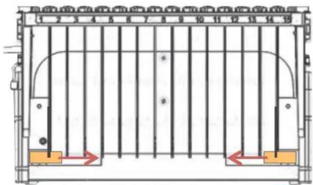
front of the module inside the cart
2. Slide Locking Tabs toward center of cart
2
back of the module inside the cart
4. Unplug the power cord and the cat 6 cable
4

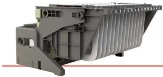
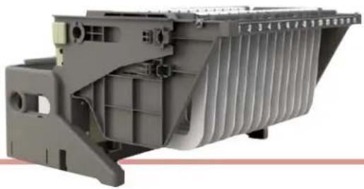
natural_image
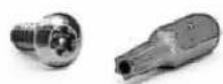
Side view of a mechanical cart with green internal components and gray frame (no visible text or symbols)- Using the handles, lift the MiX Module out of the cart and set on a work surface
USER GUIDE | MiX Carts // EVER CARTS
natural_image
3D cutaway view of a mechanical component with internal channels and mounting holes (no visible text or symbols)Adjust the Slot Width on the MiX Module
- Set the MiX Module on a comfortable work surface where you will make all of the adjustments for storing and charging your devices.
-
It is suggested that your collection of devices be close at hand, with each adapter/cord set with its own device.
-
Adjust the Slot Width Your EVER Cart ships with the slot width of the MiX Modules set at 1" intervals. Measure the "height" of your device as it sits closed on the work surface. This is the way the device will stand in the slot, and this dimension establishes the "slot width". If your device height is less than 1", then leave the 1" slots alone and move on to cable management.
-
If your device is taller than 1" and less than 1 1/4", then you will need to adjust the dividers to be 1 1/4" wide, or 1.25" wide. You will need to remove all of the dividers and reinstall them at the 1.25" width. The MiX Module makes this exercise very simple.
-
First, release each of the dividers by pinching the white tabs on top of the Mix Module .... pinch between finger and thumb until the divider pops out. Remove the dividers to a safe place out of your way.
-
Next, with the MiX Module facing forward directly at you. locate the locking buttons on both sides of the MiX Module - little square buttons that when depressed in, allow the whole top assembly of the MX Module to side forward toward you on the rails.
-
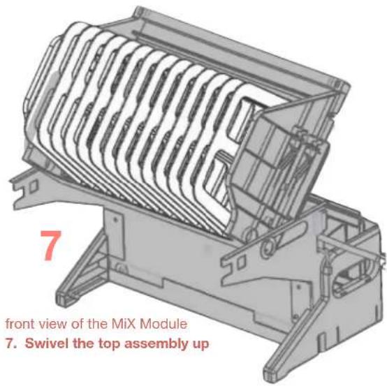
Top assembly is now free to swivel up, revealing the mounting pattern for the dividers in an easier position for reattaching the dividers at the appropriate position.
-
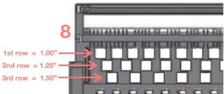
Reinsert the dividers using the white knobs as the guide into the row of holes which matches your desired slot width (as illustrated below). NOTE: When reinserting the dividers for either 1.25" or 1.50" wide slots, the dividers get turned 180 degrees so that they will fit into the pattern.
-
This process is identical for both 1.25" and 1.50" wide.
-
When complete, swivel the top assembly back down and slide back on the rails until the locking buttons click on both sides
- Change the Slot Identification Rail to match the number of slots you now are using - either 15, 12 or 10. NOTE: The numbers will advance from the top module to the middle module to the lower module:
| 1-15 | 16-30 | 31-45 | 1 bump on the rails' end |
| 1-12 | 13-24 | 25-36 | 2 bumps on the rails' end |
| 1-10 | 11-20 | 21-30 | 3 bumps on the rails' end |
5
natural_image
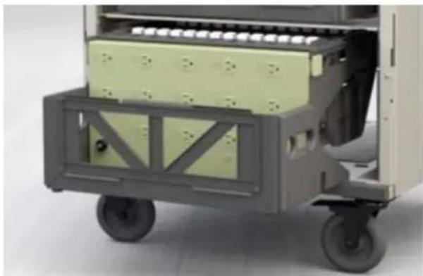
Diagram of a multi-chamber electronic device with slots and connectors (no text or labels)top down view of the MiX Module
5. Pinch the white tabs to release the dividers
natural_image
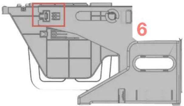
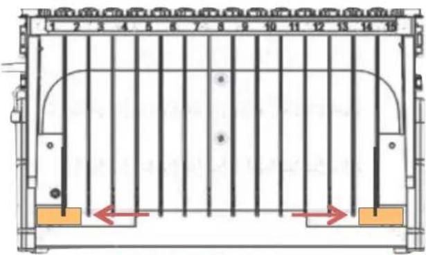
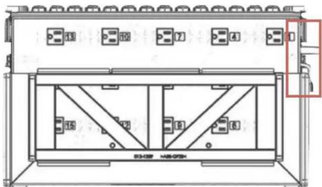
Technical diagram of a mechanical housing or enclosure with internal components and a highlighted component (no text or symbols)right side view of the MiX Module
6. Depress locking button on both sides of the module so the top assembly slides forward on the rails
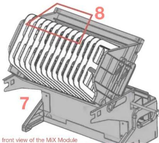
- Swivel the top assembly up & over, revealing the pattern for attaching the dividers (8)
USER GUIDE | MiX Carts // EVER CARTS
Height Adjust the MiX Module
- Set the MiX Module on a comfortable work surface where you will make all of the adjustments for storing and charging your devices.
- It is suggested that your collection of devices be close at hand, with each adapter/cord set with its own device.
- Adjust the Height of the MiX Module Your EVER Cart ships with the the MiX Modules set at 10" height. Measure the "depth" of your device as it will sit in the slot of the MiX Module.. This is the way the device will stand in the slot, and this dimension establishes the "slot height". If your device height is less than 10", then leave the height alone and move on to cable management.
- If your device is deeper than 10", then you will need to adjust the Height of the MiX Module to its 12" high setting.
- Start by removing two dividers from each side of the MiX Module
- Then, with the MiX Module facing forward directly at you. locate the locking buttons on both sides of the MiX Module - little square buttons that when depressed in, allow the whole top assembly of the MX Module to side forward toward you on the rails.
- Top assembly is now free to swivel up.
- Using the illustrations below, swivel the top assembly up until it is perpendicular to the frame. Find the Height Adjust Caps on both sides of the Module.
- Hold the top assembly so that both the Height Adjust Cap and the 2nd adjustment hole are both visible through the Height Adjust Slot.
- Keeping the top assembly steady with one hand, remove the Height Adjust Cap with the other hand and reinsert into the 2nd adjustment hole. Repeat on the opposite side of the top assembly.
natural_image
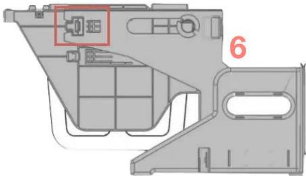
Technical diagram of a device casing with internal compartments and mounting points, labeled with number 6 (no text or symbols beyond label)right side view of the MiX Module
- Depress locking button on both sides of the MiX Module, which then allows the top assembly to slide forward on the rails.
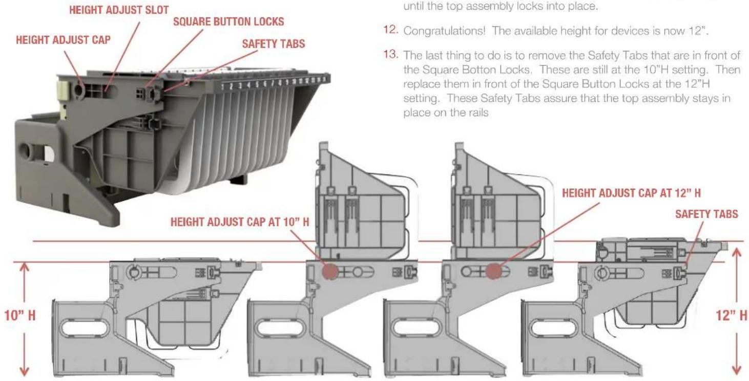
- Swivel the top assembly back down onto the rails and push back until the top assembly locks into place.
- Congratulations! The available height for devices is now 12".
- The last thing to do is to remove the Safety Tabs that are in front of the Square Botton Locks. These are still at the 10"H setting. Then replace them in front of the Square Button Locks at the 12"H setting. These Safety Tabs assure that the top assembly stays in place on the rails
natural_image
3D cutaway view of a mechanical component with ribbed structure (no visible text or symbols)Cable Management on the MiX Module ... AC version
- Set the MiX Module AC on a comfortable work surface where you will make all of the adjustments for storing and charging your devices.
- It is suggested that your collection of devices be close at hand, with each adapter/cord set with its own device.
- Cable Manage Your Devices Be sure that each of the adapter cable sets for your devices are the correct components for the devices you are installing into your new cart. Now is the time to place an identifying sticker on the adapter, if you so choose.
- Take the computer plug cable from your first adapter cable set and lay it loosely across the top assembly of the MiX Module. The cable will be running from back to front, hanging down in the slot at the front of the MiX Module.
- For ease of filling the rear cable bin, it is suggested that you begin with the outlets closest to the bottom of the bin #3, #6, #9, #12, #15
- On the top assembly, the computer plug cables will run between the white knobs - these represent where the divider is positioned, and the adapter cable will be in the best position if it lays between the white knobs, right in the middle of the device slot.
- Measure how far down from the top surface the computer plug needs to drop down in front of the slot to plug into the device. This will be the standard dimension length for each of the adapter cables.
- In the rear of the MiX Module go ahead and wrap the adapter and extra power cord and extra computer cord, and place the wrapped adapter in the cable bin. Plug in the adapter into the AC outlet that corresponds to the slot you are populating on the front of the MiX module. #3 outlet to #3 slot, #6 outlet to #6 slot, and so on. The length of each adapter's power cord to its designated outlet will vary from wrapped adapter to wrapped adapter, as you move up to the 2nd row of outlets.
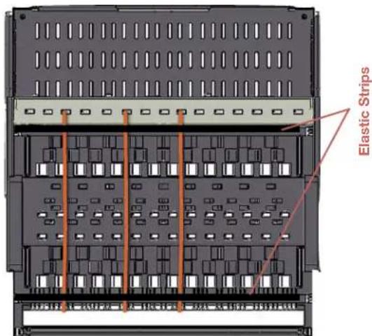
- On the top assembly, there are two elastic strips - front and back of the top assembly - which will help control the cables as they travel across the top assembly. Once you have plugged in the adapter cable set, and you have left the proper amount of cable to plug into the device, go ahead and run that part of the cable under the elastic, to hold it in position.
- Continue to fill the cable bin, plugging in the adapter cable sets and checking the length of cables at the from of the MiX Module to be sure you have enough length to plug into the computer.
- When complete, you are ready to replace the MiX Module back into the EVER Cart.
- But before you do that, you will need to change the steel shelf height inside the EVER Cart IF you changed the height of the MiX Modules to the 12"high position - you can only fit 2 Mix Modules if they are 12" high.
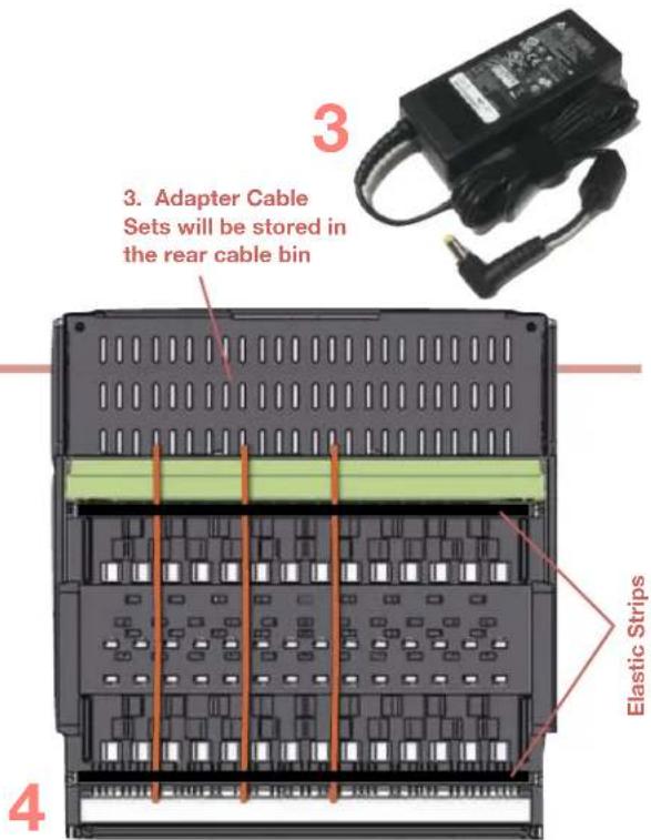
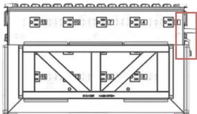
top down view of the MiX Module AC
4. Lay the computer plug cable across the top assembly of the MiX Module, from back to front. Illustrated here as Orange cables., in slots #3, #6 and #9
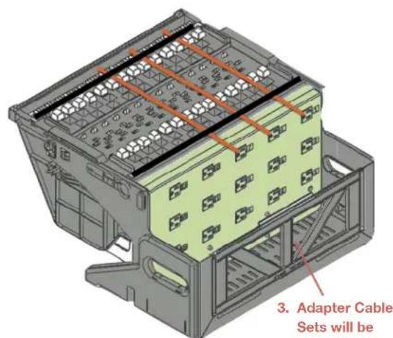
top & rear view of the MiX Module AC
3. Adapter Cable Sets will be stored in the rear cable bin

top & front view of the MiX Module AC
USER GUIDE | MiX Carts // EVER CARTS
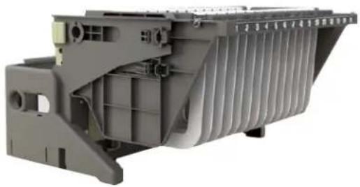
natural_image
3D cutaway view of a mechanical component with internal channels and mounting holes (no visible text or symbols)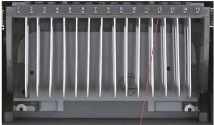
natural_image
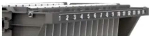
Front view of a rack-mounted server unit with vertical cooling fins and numbered slots (no visible text or symbols)Cable Management on the MiX Module ... USB version
- Set the MiX Module USB on a comfortable work surface where you will make all of the adjustments for storing and charging your devices.
- It is suggested that your collection of devices be close at hand, with each USB cord set with its own device.
- The USB version of the MiX Module has USB ports along the top of the light grey colored Power Box. And below each USB Port is a built-in cord-winder, for organizing extra cable.
- Cable Manage Your Devices Be sure that each of the USB cable sets for your devices are the correct cables for the devices you are installing into your new cart.
- Take the device plug end of the cable for your first device and lay it loosely across the top assembly of the MiX Module USB. The cable will be running from back to front, hanging down in the slot at the front of the MiX Module.
- Take the USB end of the cable, and plug it into the USB Port that coincides with the first slot. Wind any extra cable around the built-in cord winder directly below the USB Port. You may wish to zip-tie the wound cables into position.
- On the Mix Module top assembly, the device plug cables will run between the white knobs - these represent where the dividers are positioned, and the adapter cable will be in the best position if it lays between the white knobs, right in the middle of the device slot.
- Measure how far down from the top surface the device cable plug needs to drop down in front of the slot to plug into the device. This will be the standard dimension length for each of the cables.
- On the top assembly, there are two elastic strips - front and back of the top assembly - which will help control the cables as they travel across the top assembly. Once you have plugged in the USB cable into its port, and you have left the proper amount of cable to plug into the device, go ahead and run that part of the cable under the elastic, to hold it in position.
- Continue to plug in and wrap the USB cable sets, checking the length of cables at the from of the MiX Module to be sure you have enough length to plug into the device.
- When complete, you are ready to replace the MiX Module back into the EVER Cart.
- But before you do that, you will need to change the steel shelf height inside the EVER Cart IF you changed the height of the MiX Modules to the 12"high position - you can only fit 2 Mix Modules if they are 12" high.
front view of the MiX Module USB
The Mix Module USB features LED indicator lights that glow amber when the device is charging, green when the device is charged. Because of these LED lights the MiX Module USB, does not feature the various number bars for designating the slot number, if the slot width is adjusted.
top down view of the MiX Module USB
Lay the device plug cable across the top assembly of the MiX Module USB, from back to front. Illustrated here as Orange cables.
natural_image
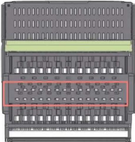
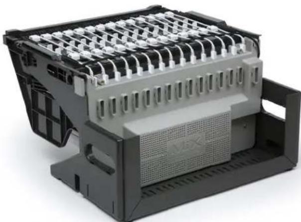
3D rendering of a mechanical component with grid-like top structure and central mesh (no visible text or symbols)rear & top view of the MiX Module USB
Shows the USP plugs in position and the built-in cord winders directly below the USB ports.
natural_image
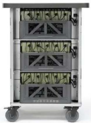
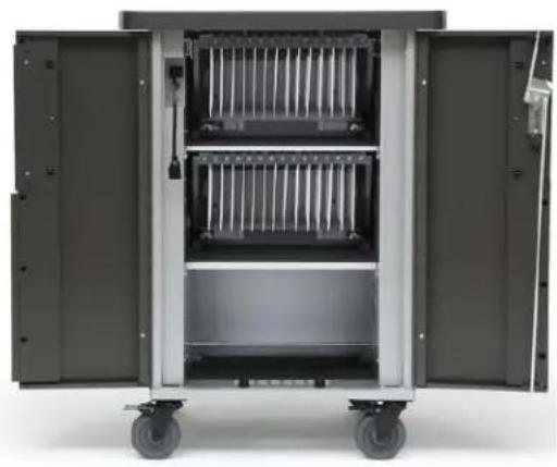
Exterior view of a multi-tiered rack-mounted server unit with visible internal components (no text or symbols)Both Rear View & Front View of the EVER Cart with shelves set to accommodate 3 MiX Modules
natural_image
Interior view of a large industrial machine with open doors and wheels (no visible text or symbols)Changing Shelf Height on the EVER Cart
- Each EVER Cart ships with the shelves at the proper height to support the 10" MiX Module. Both the EVER Cart for 30 Devices with 2 MiX Modules and the EVER Cart for 45 devices with 3 MiX Modules.
- In the event you have determined that your devices require more than that 10" height, then you have already adjusted the height of your MiX Modules to the 12" high setting.
- You can only fit 2 of the 12"H MiX Modules in the EVER Cart. So you will need to reset the 2 steel shelves in the EVR Cart to the height settings for those 2 MiX Modules.
- Changing the steel shelf height inside your EVER Cart Start by removing the MiX Modules from inside your EVER Cart. that leaves you with 2 steel shelves that are held in place with tabs and screws.
- Using a screwdriver, remove the 4 phillips head screws that hold each of the steel shelves in place..
- The 2 shelves are now sitting on tabs. With the help of a 2nd person at the back of the cart, lift the lower steel shelf off of its tabs and lower the steel shelf to the next set of tabs down .... about 3" below: from approximately 11" from the inside bottom of the cart down to the tabs that are approximately 7" from the inside bottom of the cart.
- Now, with the help of a 2nd person at the back of the cart, lift the higher steel shelf off its tabs and lower the steel shelf to the next set of tabs down .... about 3" below: from approximately 23.5" from the inside bottom of the cart down to the tabs that are approximately 20.5" from the inside bottom of the cart.
- Replace the Phillips head screws, 4 in each shelf.
- You are now ready to reinstall the MiX Modules into your EVER Cart. Since you changed the height of the steel shelves, you should only be installing 2 of the Mix Modules set at the 12" height.
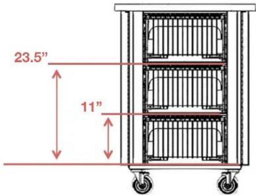
3 Module EVER Cart with shelves set for 10"H MiX Modules
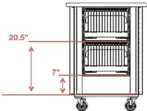
2 Module EVER Cart with shelves set for 12"H MiX Modules

natural_image
3D cutaway view of a mechanical component with internal channels and mounting holes (no visible text or symbols)MiX
MODULE SYSTEM™
natural_image
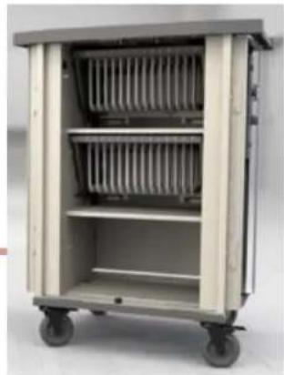
Exterior view of a multi-level medical or laboratory cart with shelves and wheels (no visible text or symbols)Reinstalling MiX Module into the EVER Cart
- Using the built-in handles, lift the MiX Module off of the work surface and place it into the EVER Cart .... carefully keeping the whole MiX Module level will aid in sliding the module onto the steel shelf, all from the back of the cart.
- The MiX Module has circular feet at the back, under the cord bin. When you feel the feet set in place into a matching hole, the MiX Module is in the correct position.
- From the front of the cart, reach in under the MiX Module dividers and slide the Locking Tabs toward the cart's interior side wall ... both sides. This locks the MiX Module inside the cart interior. No locking screws or latches required.
- From the back of the cart, replug the power cord from each MixModule into the outlet provided, and reinsert the Cat 6 Cable.
- At the back of the cart, Lift the Back Panel back onto the chassis. Re-screw either the two security screws using the Security Bit provided, or the Thumb Screws, if security is not an issue. This locks the back panel onto the cart..
- The EVER Cart is now ready to accept your electronic devices from the front, one device per slot.
- Replug the external power cord into its socket on the cord winder ... you are now ready to plug the cart into a wall outlet, and start using the cart with your devices. Read Warnings on Front Page.
natural_image
Exterior view of a gray industrial cart with wheels and a door handle (no visible text or symbols)- Lift the back panel onto the cart and lock in place using either the Thumb Screws or the Security Screws - one on each side of the cart at the back.
Security Screws
Your new EVER Cart comes equipped with 2 Security Screws and a Security Bit, included in the hardware pack.
Replace the Thumb Screws with the Security Screws if you need to restrict access to the computer adapters in the back of the cart.
natural_image
Side view of a mechanical cart with green panel and gray frame, no visible text or symbols- Using the handles, lift the MiX Module back into the EVER Cart.
1
front of the module inside the cart
3. Slide Locking Tabs away from center of cart
3
back of the module inside the cart
4. Plug in the power cord and the cat 6 cable
4

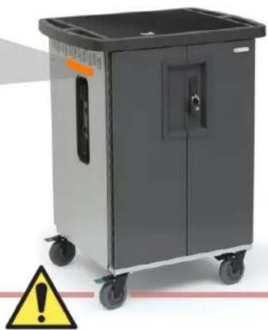
"WARNING": This Safe User Label is attached to the side of the cart, warning that the cart may tip over if transported incorrectly, which could cause injury.
- Do not allow children under 16 to move cart. Only adults should move this cart.
- Move the cart slowly
- Apply moving force on the narrow dimension.
• Always push using the handles. Push the cart, do not pull it. - Engage the directional lock casters when moving the cart for added stability & safety.
natural_image
Exterior view of a gray industrial machine with wheels and control panel (no visible text or symbols)"WARNING": Relocating audio and/or video devices to a cart not specifically designed to support audio and/or video devices may result in death or serious injury due to the cart collapsing or over turning onto a child.
"WARNING": Death or serious injury may occur when children climb on a cart. A remote control or toys placed on the cart may encourage a child to climb on the cart and as a result, the cart may tip over on to the child.
Safe Use Instructions
• The socket outlet shall be installed near the cart and shall be easily accessible.
• Make sure all devices do not exceed the maximum load rating of 12 amps.
- Power strips inside cart are intended only for charging compatible devices. Any other use may cause overload.
- Do not move cart by pulling the power cord. Before moving cart from one room to the next, wrap power cord around the cord winder located on the side of the cart.
- Do not plug the cart in if the switch, receptacle(s), or power cord has been damaged. Contact Bretford or a qualified electrician before attempting to make any type of electrical repair or parts replacement.
• Engage locking casters when cart is not in transit.
- Do not block ventilation holes on cart. Proper air flow is required for safe operation.
- Cart is not designed to be operated by a child or student. Adult operation and supervision is recommended at all times.
• Liquids should not be stored in, set on or placed inside the cart.
- Only clean the surfaces of cart with soft dry cloth. Do not use liquid or spray or abrasive cleansers. Use only disinfecting wipes containing no bleach.
• Product is for indoor use only.
• User can plug in up to 45 devices at one time.
• Turn power switch off before plugging in devices
• Turn power switch off before unplugging the cart.
- Do not pull the cart. Always push cart using the handles. Use extra caution on ramps and thresholds.
- Do not plug the power cord into another extension cord or re-locatable power tap.
- Be sure to turn power switch off and unplug cart before moving to a different location.
- Ensure casters are locked before opening the cart doors.
- Be sure to lock up cart in a secure environment after every use.
• do not share the lock combination code with any unauthorized persons.