NetDirector B064-032-01-IPG - Network switch Tripp Lite - Free user manual and instructions
Find the device manual for free NetDirector B064-032-01-IPG Tripp Lite in PDF.

User questions about NetDirector B064-032-01-IPG Tripp Lite
0 question about this device. Answer the ones you know or ask your own.
Ask a new question about this device
Download the instructions for your Network switch in PDF format for free! Find your manual NetDirector B064-032-01-IPG - Tripp Lite and take your electronic device back in hand. On this page are published all the documents necessary for the use of your device. NetDirector B064-032-01-IPG by Tripp Lite.
USER MANUAL NetDirector B064-032-01-IPG Tripp Lite
NetDirector Cat5 IP KVM Switches
Models:
B064-008-01-IPG, B064-016-01-IPG, B064-016-02-IPG, B064-016-04-IPG, B064-032-01-IPG, B064-032-02-IPG, B64-032-04-IPG and B064-064-08-IPG
Package Contents
This package contains:
(1) B064-008-01-IPG, B064-016-01-IPG, B064-016-02-IPG, B064-016-04-IPG, B064-032-01-IPG, B064-032-02-IPG, B64-032-04-IPG or B064-064-08-IPG
(2) Power Cords - C13 to 5-15P Connectors
(1) RJ45 Female to DB9 Male Adapter
(1) Grounding Wire
(1) Rack-Mount Kit
(1) Set of Foot Pads
(1) CD (Includes Owner's Manual, Quick Start Guide and Device Files)
(1) Quick Start Guide
WARRANTY REGISTRATION
Register your product today and be automatically entered to win an ISOBAR surge protector in our monthly drawing!
www.tripplite.com/warranty


text_image
TRIPP·LITE
1111 W. 35th Street, Chicago, IL 60609 USA • www.tripplite.com/support
Copyright © 2019 Tripp Lite. All rights reserved. All trademarks are the property of their respective owners.
Table of Contents
Table of Contents....2
Introduction 3
Important Safety Notice....3
Features 3
Remote Console Computer Requirements. 4
Connected Computer/Server Requirements. 4
Server Interface Units (SIUs)....4
Supported Operating Systems 4
Supported Browsers....5
Components 5
Hardware Setup 7
General Safety Instructions 7
Stacking 8
Rack Mounting....8
Single-Stage Installation 8
Two-Stage Installation 9
Laptop USB Console (LUC) 10
Hot Plugging 10
Powering Off & Restarting 10
Port ID Numbering 10
Super Administrator Setup....11
First Time Setup....11
Network Setup - IP Address Determination....11
Changing the Super Administrator Login 13
Logging Into the B064-Series KVM Switch....13
Local Console Login 13
Browser Login 14
AP Windows Client Login 14
AP Java Client Login 15
OSD Operation....16
The OSD Main Page 16
OSD Tab Bar 17
Port Access....17
Connections 18
History 22
Favorites....23
User Preferences 24
Sessions 25
Access 25
Port Configuration 26
Multi-View Configuration 28
Blade Configuration....29
User Management 30
Device Management 36
Device Information 36
Operating Mode 37
Network 37
Advanced Network Management Settings....39
OOBC 47
Security 48
Date/Time....53
Blade Server Configuration 53
Log 55
Maintenance. 56
Download....59
Remote Session Operation 60
Control Panel 60
The OSD Toolbar 71
Multiuser Operation....73
Auto Scanning 73
The Log Server....74
Installation 74
Starting Up....74
The Menu Bar 74
Configure 75
Events. 76
Options....77
Help 77
The Log Server Main Screen - Overview 77
Appendix....79
Keyboard Emulation 79
General Operation Troubleshooting....80
Administration Troubleshooting 80
Mouse Troubleshooting....81
Virtual Media Troubleshooting 81
AP Windows Client Troubleshooting 81
WinClient ActiveX Viewer Troubleshooting....82
Panel Array Mode Troubleshooting 82
Java Applet & AP Java Client Troubleshooting....82
Log Server Troubleshooting 83
Sun Systems Troubleshooting 83
Specifications 84
Factory Default Settings....84
Serial Adapter Pin Assignments....84
Fan Location & Speed Information....85
Temperature Sensor Location 85
Product Registration 86
Introduction
Important Safety Notice

BATTERY SAFETY NOTICE
- There is a risk of explosion if the battery is replaced with an incorrect type. Dispose of used batteries according to the relevant instructions.

BATTERIE AVIS DE SÉCURITÉ
- Directly connect up to 8 (B064-008-01-IPG), 16 (B064-016-01-IPG, B064-016-02-IPG, B064-016-04-IPG), 32 (B064-032-01-IPG, B064-032-02-IPG, B064-032-04-IPG) or 64 (B064-064-08-IPG) computers/servers
- Accomodate additional computers/servers in a two-level cascade installation
- Two 10/100/1000 Mbps network connections for redundant LAN or two IP operation
• Supports both IPv4 and IPv6 - Blade server support
- Supports up to 1 (B064-008-01-IPG, B064-016-01-IPG, B064-032-01-IPG) or 2 (B064-016-02-IPG, B064-032-02-IPG) or 4 (B064-016-04-IPG, B064-032-04-IPG) or 8 (B064-064-08-IPG) remote sessions
- 1 Local and 1 Remote User can simultaneously access the B064-008-01-IPG, B064-016-01-IPG or B064-032-01-IPG
- 1 Local and 2 Remote Users can simultaneously access the B064-032-02-IPG or B064-016-02-IPG
- 1 Local and 8 Remote Users can simultaneously access the B064-064-08-IPG
- 1 Local and 4 Remote Users can simultaneously access the B064-016-04-IPG or B064-032-04-IPG
- Up to 32 users can remotely share one user port
• Create up to 64 user accounts - Multi-level authentication: super administrator; administrator; user
- Advanced security features include password protection and advanced encryption technologies – 1024 bit RSA; 56 bit DES; 256 bit AES; and 128 bit SSL
- RJ45 connectors and Cat5e cable allow for a more efficient installation
- Browser access can be disabled – Windows ^® and Java GUI AP programs provided for non-browser connectivity
- Graphical OSD and toolbars provide convenient, user-friendly operation
• Full-screen graphical OSD for the local console - Full-screen or sizable remote desktop window; in full-screen mode the remote desktop display scales to user's monitor display size
- Panel Array Mode displays up to 32 ports at the same time
- High video resolution: up to 1920 x 1200 @ 60Hz – 24 bit color depth for the local console; up to 1920 x 1200 @ 60Hz with 24 bit color depth for remote sessions at up to 164 ft. (50 m)
- Features advanced FPGA graphics processor for improved video quality
-
Multi-language support; OSD can be displayed in English, Spanish, French, German, Russian, Italian, Japanese, Korean, traditional Chinese and simplified Chinese
-
Software (on-screen) keyboard
- UltraSync for USB mice – local and remote mouse movement are the same – no need to constantly re-sync the two movements
- Windows-based Log Server
- Support all major server platforms and VT100-based serial devices
• Support multi-platform server environments: PS/2 and USB - Support 10Base-T, 100Base-T, 1000Base-T, Auto-Sense, TCP/IP, HTTP, DNS, DHCP, UDP, ARP, Ping
- Remote authentication support: RADIUS, LDAP, LDAPS, and Active Directory
- Flash upgradeable firmware over the network
- Server Interface Unit (SIU) information is stored by the KVM switch. When switched to a different port, the port settings (Port OS, OS Language, etc.) for the SIU are transferred along with it
- Virtual Media allows computers connected to the KVM switch by a B055-001-USB-V2 SIU to access DVD/CD drives, flash drives and other storage media as if they were directly connected to the computer (works in either the operating system or BIOS level)
- Includes three USB ports on the front of the unit that can be used for an external keyboard and mouse or for virtual media functionality
- Dual power supplies allow the unit to continue running in the event one power supply ceases to receive power. If one power supply fails, the other powers supply takes over to keep the unit powered and functional.
- Temperature sensors determine if fans are needed to cool the device and at what speed. The fan speed increases/decreases along with the temperature, using energy more efficiently and increasing the life of the fans and switch.
- Track critical events on the installation via SMTP email notification, SNMP traps, the included Windows-based Log Server or Syslog server
- Users can choose between any combination of 56-bit DES, 168-bit 3DES, 256-bit AES, 128-bit RC4 or Random for independent Keyboard/Mouse, video and virtual media data encryption
• Support Exit Macros - BIOS level access
- Supports Link Local IPv6 Address and IPv6 Stateless Autoconfiguration protocols
- Modem out of band Dial In, Dial Out, Dial Back support
- Automated Certificate Signing Request (CSR) creation utility
• Supports importing third party CA certificates
• Supports IPS 140-2 level 1 security standards - Local monitor's EDID information stored in connected Server Interface Units (SIUs) for optimal display resolution
Introduction (continued)
Remote Console Computer Requirements
- Browsers must support 128-bit SSL encryption
- For the browser-based Java Applet and non-browser AP Java Client, the latest version of Sun's Java Runtime Environment (JRE) must be installed, and 250 MB of memory available after installation
- For the Log Server, you must have the Microsoft Jet OLEDB 4.0 or higher driver installed
-
For best results we recommend that the computers used to access the switch have at least a Pentium III, 1 GHz processor, with their screen resolution set to 1024 x 768
-
For best results, a network transfer speed of at least 512 kbps is recommended
- For the browser-based Windows Client, DirectX 8 must be installed, and at least 150MB of memory available after installation
- For the non-browser AP Windows client, DirectX 8 must be installed, and at least 90MB of memory available after installation
- Internet Explorer 8 or later
Connected Computer/Server Requirements
Computers/servers to be connected to the B064-Series KVM Switch must have the following:
• VGA, SVGA or Multisync port
- For USB Server Interface Unit Connections: Type A USB port and USB host controller
- For PS/2 Server Interface Unit Connections: 6-pin mini-DIN keyboard and mouse ports
Server Interface Units (SIUs)
Cat5e/6 cable is required to connect the B064-Series KVM Switches to one of the Server Interface Units (SIUs). The following SIUs are required for use with the B064 Series KVM Switch:
Function SIU
| Connect to a computer/server with PS/2 ports – 164 ft. (50 m) Max Distance B054-001-PS2 | |
| Connect to a computer/server with PS/2 ports – 164 ft. (50 m) Max Distance B055-001-PS2 | |
| Connect to a computer/server with USB ports – No Virtual Media Support; 164 ft. (50 m) Max Distance B054-001-USB | |
| Connect to a computer/server with USB ports – No Virtual Media Support; 164 ft. (50 m) Max Distance B055-001-USB | |
| Connect to a Sun computer/server with USB ports – 164 ft. (50 m) Max Distance B054-001-SUN | |
| Connect to a computer/server with USB ports – Supports Virtual Media; 164 ft. (50 m) Max Distance | B055-001-USB-V2 |
| Connect to a serial based device – 492 ft. (150 m) Max Distance B055-001-SER |
Note: SIUs that were purchased prior to that of your KVM switch may require a firmware upgrade in order for them to work properly (see Maintenance under OSD Operation section for details).
Supported Operating Systems
Supported operating systems for computer/servers that connect to the B064-Series KVM switches are shown in the table at right:
Supported operating systems for users that remotely log into the B064-Series KVM Switches include Windows 2000 and higher, and those capable of running Sun's Java Runtime Environment (JRE) 6, Update 3, or higher.
| OS Version | |
| Windows 2000 and higher | |
| Linux® Red Hat 7.1 and higher | |
| Linux Fedora Core 2 and higher | |
| Linux SuSE 9.0 and higher | |
| Linux Mandriva 9.0 and higher | |
| UNIX® AIX | 4.3 and higher |
| UNIX FreeBSD 4.2 and higher | |
| UNIX Sun | Solaris 8 and higher |
| Novell® Netware® | 5.0 and higher |
| Mac® | OS 9 and higher |
| DOS | 6.2 and higher |
Introduction (continued)
Supported Browsers
Supported browsers for users that remotely log into the B064-Series KVM Switches include:
| Browser Version | |
| Internet Explorer ^ 8 and higher | |
| Firefox ^ | 3.5 and higher |
| Mozilla ^ | 1.7 and higher |
| Safari ^ | 4.0 and higher |
| Opera ^ | 10.0 and higher |
| Netscape Navigator ^ | 9.0 and higher |
Components
Front View
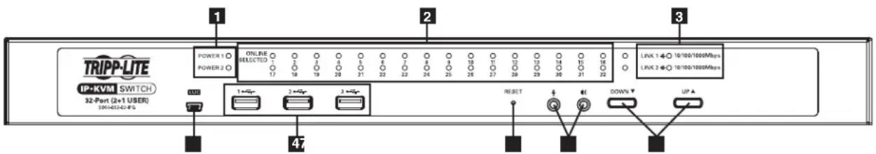
text_image
TRIPP-LTE IP+KVM SWITCH 32-Port (2+1 USER) 10k+4324-PS POWER 1 POWER 2 ONLINE SELECTED 17 18 19 20 21 22 23 24 25 26 27 28 29 30 31 32 LINK 1 ←○ 10/100/1000Mbps LINK 2 ←○ 10/100/1000Mbps 1 → 2 → 3 → RESET ↓ ← DOWN ↓ UP ↑No. Component Description
1 Power LEDs Depending on which power supply is providing power, the POWER 1 or POWER 2 LED will illuminate when the KVM switch is turned on.
2 Port LEDs Port LEDs will illuminate in colors corresponding to the status of the port:
Green - Illuminate green when the corresponding port is connected and powered-on
Red - Illuminate red when the corresponding port is selected as having the KVM's focus, but is either not connected to a computer/server or is connected to a computer/server that is not powered-on
Orange – Illuminate orange when the corresponding port is connected, powered-on and selected as having the KVM's focus
Note: The Port LEDs are steady under normal conditions, but will flash at half second intervals when the corresponding port is being accessed under Auto Scan Mode or Skip Mode.
3 LAN LEDs The Primary (Link 1) and Secondary (Link 2) LAN LEDs will illuminate in colors corresponding to the network transfer rate:
Red - Illuminate red at speeds of 10 Mbps
Orange - Illuminate orange at speeds of 100 Mbps
Green - Illuminate green at speeds of 1000 Mbps
4 USB Ports Note: Only computers connected to the KVM by a B055-001-USB-V2 can access the KVMs Virtual Media functionality. Additional USB ports support external keyboard and mouse, as well as virtual media functionality.
5 Reset Button Note: This recessed button must be pushed with a thin object, such as the end of a paper clip or a ballpoint pen.
- Pressing and releasing the Reset Button when the KVM switch is running performs a system reset.
- Pressing and holding the Reset Button in for more than three seconds when the KVM switch is running resets the switch configuration to the factory default settings. Note: This does not clear User Account information.
- Pressing and holding the Reset Button in while powering on the switch will restore the KVM switch to its original firmware in the event of a firmware upgrade failure. Note: This operation should only be performed in the event of a firmware upgrade failure that results in the device becoming inoperable.
6 Port Switching Buttons • Press the Port Down button to switch from the current port to the previous port on the installation.
- Press the Port Up button to switch from the current port to the next port on the installation.
7 Laptop USB Console (LUC) Port A USB port that allows for direct connection of a laptop to the switch for easy console operation.
8 Audio Ports Speakers and microphone plug in here.
Note: The figure shows the front panel of a B064-032-02-IPG. The B064-032-04-IPG, B064-016-02-IPG and B064-016-04-IPG contain all the same front-panel features as the B064-032-04-IPG, except the B064-016-04-IPG and B064-016-02-IPG come with 16 ports instead of 32.
Introduction (continued)
Components (continued)
Rear View
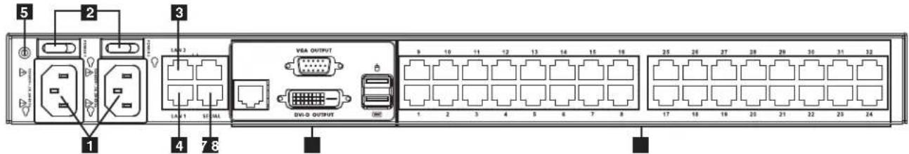
text_image
5 2 3 1 4 7 8 VEA OUTPUT DV-D OUTPUT 9 10 11 12 13 14 15 16 1 2 3 4 5 6 7 8 25 26 27 28 29 30 31 32 17 18 19 20 21 22 23 24No. Component Description
1 Power Sockets (C14)
The two C14 power sockets are located here. Connect the included power cords (C13 to 5-15P) from here to an appropriate power source. Note: To help protect your system from sudden, transient increases and decreases in electrical power, it is recommended that you plug your devices into a Tripp Lite surge protector, line conditioner or uninterruptible power supply (UPS).
2 Power Switches The On/Off switches for the two power supplies are here.
3 Secondary LAN Port (LAN 2) The cable that connects the KVM switch to the backup network plugs in here.
4 Primary LAN Port (LAN 1) The cable that connects the KVM switch to the primary network plugs in here.
5 Grounding Terminal Connect the included grounding wire to this terminal to ground the KVM switch.
6 Modem Port An optional dial-in connection is available for use in the event the KVM switch is not available over the Primary or Secondary networks.
7 Local Console Ports This area features VGA and DVI ports for the connection of either a VGA or DVI monitor, as well as two USB ports for the connection of a keyboard and mouse. Note: The B064-008-01-IPG and B064-016-01-IPG will not feature a DVI-D port but instead two PS/2 ports for connection of mouse and keyboard.
8 Server Ports Cat5e/6 cable connects between these ports and the SIUs to connect computer/servers to the KVM switch.
Note: The figure above shows the rear panel of a B064-032-04-1PG or B064-032-02-1PG. The B064-016-04-1PG and B064-016-02-1PG differ in that it only has a single block of 16 KVM ports.
Hardware Setup

WARNING
Class I Equipment. This equipment must be earthed. The power plug must be connected to a properly wired earth ground socket outlet. An improperly wired socket outlet could place hazardous voltages on accessible metal parts.

AVERTISSEMENT
62368-1 Clause Equipment for Installation:
Suitable for installation in Information Technology Rooms in accordance with Article 645 of the National Electrical Code and NFPA 75.
- Read all of these instructions. Save them for future reference.
- Follow all warnings and instructions marked on the device.
- Use of this equipment in life support applications where failure of this equipment can reasonably be expected to cause the failure of the life support equipment or to significantly affect its safety or effectiveness is not recommended. Do not use this equipment in the presence of a flammable anesthetic mixture with air, oxygen or nitrous oxide.
- This device is designed for IT power distribution systems with up to 230V phase-to-phase voltage.
- Do not place the device on any unstable surface (cart, stand, table, etc.). If the device falls, serious damage will result.
- Do not use the device near water.
- Do not place the device near, or over, radiators or heat registers.
- The device cabinet is provided with slots and openings to permit adequate ventilation. To ensure reliable operation and protect against overheating, these openings must never be blocked or covered.
- The device should not be placed on a soft surface (bed, sofa, rug, etc.), as this will block its ventilation openings. Likewise, the device should not be placed in a built-in enclosure unless adequate ventilation has been provided.
- Never spill liquid of any kind on the device.
- Unplug the device from the wall outlet before cleaning. Use a damp cloth for cleaning. Do not use liquid or aerosol cleaners.
- The device should be operated from the type of power source indicated on the marking label. If you are not sure of the type of power available, consult your dealer or local power company.
- To prevent damage to your installation, ensure that all devices are properly grounded.
- The device is equipped with a 3-wire grounding type plug. This is a safety feature. If you are unable to insert the plug into the outlet, contact your electrician to replace your obsolete outlet. Do not attempt to defeat the purpose of the grounding-type plug. Always follow your local/national wiring codes.
- Position system cables and power cables carefully to ensure that nothing rests on any cable. Route the power cord and cables so that they cannot be stepped on or tripped over.
- If an extension cord is used with this device, make sure that the total ampere rating of all products used on the cord does not exceed the extension cord ampere rating. Make sure that the total of all products plugged into the wall outlet does not exceed 15 amperes.
- To help protect your system from sudden transient increases and decreases in electrical power, it is recommended that you plug your devices into a Tripp Lite surge protector, line conditioner, or uninterruptible power supply (UPS).
- When connecting or disconnecting power to hot-pluggable power supplies, observe the following precautions:
Install the power supply before connecting the power cable to the power supply
Unplug the power cable before removing the power supply
If the system has multiple sources of power, disconnect power from the system by unplugging all power cables from the power supplies
Never push objects of any kind into or through cabinet slots. They may touch dangerous voltage points or short out parts, resulting in a risk of fire or electrical shock
Do not attempt to service the device yourself. Refer all servicing to qualified service personnel
- If the following conditions occur, unplug the device from the wall outlet and bring it to qualified service personnel for repair:
The power cord or plug has become damaged or frayed
Liquid has been spilled into the device
The device has been exposed to rain or water
The device has been dropped or the cabinet has been damaged
Hardware Setup (continued)
The device exhibits a distinct change in performance, indicating a need for service
The device does not operate normally when the operating instructions are followed
- Adjust only those controls that are covered in the operating instructions. Improper adjustment of other controls may result in damage that will require extensive repair work by a qualified technician.
- Do not connect the RJ11 connector marked "UPGRADE" to a public telecommunication network.
Rack Mounting Safety Instructions
- Before working on the rack, make sure that the stabilizers are secured to the rack, extended to the floor, and that the full weight of the rack rests on the floor. Install front and side stabilizers on a single rack or front stabilizers for joined multiple racks before working on the rack.
• Always load the rack from the bottom up, and load the heaviest item in the rack first. - Make sure that the rack is level and stable before extending a device from the rack.
- Use caution when pressing the device rail release latches and sliding a device into or out of a rack; the slide rails can pinch your fingers.
• After a device is inserted into the rack, carefully extend the rail into a locking position, and then slide the device into the rack. - Do not overload the AC supply branch circuit that provides power to the rack. The total rack load should not exceed 80 percent of the branch circuit rating.
- Make sure that all equipment used on the rack, including power strips and other electrical connectors, is properly grounded.
- Ensure that proper airflow is provided for devices in the rack.
- Ensure that the operating ambient temperature of the rack environment does not exceed the maximum ambient temperature specified for the equipment by the manufacturer.
- Do not step on or stand on any device when servicing other devices in a rack.
Stacking
The KVM switch can be placed on any level surface that can safely support its weight plus the weight of attached cables. When placing the KVM switch on a desktop, remove the backing material from the rubber feet that came with this package and affix them to the switch's bottom panel at the corners.
Note: To ensure adequate ventilation, allow at least 2 inches (5 cm) on each side, and 5 inches (13 cm) at the back for power cord and cable clearance.
Rack Mounting
The KVM switch can be mounted in a 19-in (1U) rack. The rack mount brackets can be installed on either the front or the back of the unit so that it can be mounted to the front or back of the rack.
- Depending on whether you front-rack mount or rear-rack mount the unit, remove the two screws located on both sides of the front or back of the unit.
- Use the screws supplied with the rack mount kit to attach the rack mount brackets to the front or rear of the unit.
- Position the device in the front or rear of the rack and align the holes in the mount brackets with the holes in the rack.
- Secure the rack mount brackets to the rack using user-supplied screws.

text_image
TRIPP-LITE IP-KVM SWITCH 32-Port (12x1 VSSR) Use user supplied hardware to attach to the rackUse the M3x8 Phillips head hex screws provided with the rack mount kit
Single-Stage Installation
In a single-stage installation, there are no additional KVM switches cascaded or daisy-chained from the B064-Series KVM. To set up a single-stage installation, refer to the following instructions and the corresponding installation diagrams.
- Make sure that power to all the devices you will be connecting, including all pre-existing devices on the installation, have been turned off.
- Optional: Plug your Local Console's keyboard, monitor, and mouse into the KVM's Local Console Ports.
- Use Cat5e cable to connect any available KVM port to a Server Interface Unit (SIU). See the chart in the Server Interface Unit section to determine the appropriate SIU.
- Connect the Server Interface Unit to the computer/server.
- Connect a Cat5e cable from the network into the KVM switch's primary network port (LAN 1).
- Optional: Connect a second Cat5e cable from the network into the KVM switch's backup (secondary) network port (LAN 2).
- Optional Dial-In Modem Connection: Use Cat5e cable to connect the KVM switch's Modem port to the included RJ45 to DB9 Adapter, and connect the adapter's DB9 connector to the modem's DB9 port.
Hardware Setup (continued)
Single-Stage Installation (continued)
- Use the included grounding wire to ground the unit. Connect one end of the wire to the grounding terminal, and the other end of the wire to a suitable grounded object.
- Plug the included power cords into the KVM switch's Power Sockets, and then into a Tripp Lite Surge Protector, Uninterruptible Power Supply (UPS) or PDU.
- Turn on the power to the KVM switch. Once it is powered up, turn on the power to the connected computers.

flowchart
graph TD
    Modem["Modem"] --> 7
    Modem --> 2
    Modem --> 3
    Modem --> 5
    Modem --> 8
    Modem --> 9
    Modem --> 6
    Modem --> 7
    Modem --> 2
    Modem --> 4
    Modem --> 3
    Modem --> 6
    Modem --> 7
    Modem --> 8
    Modem --> 9
    Modem --> 2
    Modem --> 4
    Modem --> 3
    Modem --> 7
    Modem --> 8
    Modem --> 9
    Modem --> 6
    Modem --> 7
    Modem --> 8
    Modem --> 9
    Modem --> 10
    Modem --> 11
    Modem --> 12
    Modem --> 13
    Modem --> 14
    Modem --> 15
    Modem --> 16
    Modem --> 17
    Modem --> 18
    Modem --> 19
    Modem --> 20
    Modem --> 21
    Modem --> 22
    Modem --> 23
    Modem --> 24
    Modem --> 25
    Modem --> 26
    Modem --> 27
    Modem --> 28
    Modem --> 29
    Modem --> 30
    Modem --> 31
    Modem --> 32
    Modem --> 33
    Modem --> 34
    Modem --> 35
    Modem --> 36
    Modem --> 37
    Modem --> 38
    Modem --> 39
    Modem --> 40
    Modem --> 41
    Modem --> 42
    Modem --> 43
    Modem --> 44
    Modem --> 45
    Modem --> 46
    Modem --> 47
    Modem --> 48
    Modem --> 49
    Modem --> 50
    Modem --> 51
    Modem --> 52
    Modem --> 53
    Modem --> 54
    Modem --> 55
    Modem --> 56
    Modem --> 57
    Modem --> 58
    Modem --> 59
    Modem --> 60
    Modem --> 61
    Modem --> 62
    Modem --> 63
    Modem --> 64
    Modem --> 65
    Modem --> 66
    Modem --> 67
    Modem --> 68
    Modem --> 69
    Modem --> 70
    Modem --> 71
    Modem --> 72
    Modem --> 73
    Modem --> 74
    Modem --> 75
    Modem --> 76
    Modem --> 77
    Modem --> 78
    Modem --> 79
    Modem --> 80
Two-Stage Installation
Up to 32 additional B064-016 KVM switches can be cascaded from your unit's KVM ports, expanding the number of connected computers/servers up to 256. In a cascaded installation, the top KVM Switch is considered the first-stage unit, the cascaded switches are considered second-stage units.
To set up a two-stage installation:
- Ensure that power to all the devices you will be connecting, including all pre-existing devices on the installation, have been turned off.
- Use Cat5e/6 cabling to connect an available KVM port on the first-stage unit to a B054-001-PS2 or B055-001-PS2 SIU.
Note: Although USB SIUs will allow you to cascade to a second-stage KVM, only PS/2 SIUs will properly display the cascaded KVM in the OSD. When connected via PS/2 SIU, the cascaded KVM will be displayed as an expandable port, allowing you to easily access the connected computers. When connected via USB SIU, the cascaded KVM will be displayed as an ordinary port. To access computers connected to the KVM, you will have to use the cascaded KVMs OSD.
- Plug the SIU's KVM connectors to the Keyboard, Video, and Mouse Console ports of the second-stage B064-016 unit.
Note: The distance between the second-stage unit and the first-stage Unit cannot exceed 164 ft. (50 m).
- Use the appropriate KVM Cable Kits (See the Second Stage KVMs owner's manual), to connect any available KVM port on the second-stage unit to the Keyboard, Video and Mouse ports of the computer/server you are installing.
Hardware Setup (continued)
Two-Stage Installation (continued)
- Plug the power cord that came with the cascaded KVM switch into its power socket, and then into a Tripp Lite Surge Protector, Uninterruptible Power Supply (UPS) or PDU.
- Repeat these steps for any other second-stage units you wish to connect.
- First power on the first-stage KVM Switch and then power on all second-stage KVM switches.
- Turn on the power to all of the connected computers/servers.
Note: The Power On sequence requires that the first-stage KVM Switch be powered on first. After the first-stage KVM Switch has been powered on, all second-stage units must be powered on. After the second-stage units have been powered on, the connected computers/servers can be powered on.
Laptop USB Console (LUC)
The front panel of the KVM switch features a USB Mini-B port, which connects to the USB port on a laptop, to provide console control of the KVM switch. To use this feature, connect your laptop to the LUC port on the front of the KVM using a USB Mini-B cable. When connected, an extra drive will appear in your computer's My Computer screen. Click on this drive to bring up the Windows and Java Non-Browser Clients. Run the desired client to access the KVM switch. The client's login screen will appear, with the KVM showing up as a USB Mass Storage device in the Login Screen's Server List. Highlight the KVM and then connect per the instructions in the AP Windows Client Login and/or AP Java Client Login sections of this manual.
Hot Plugging
The B064-Series KVM Switches support hot plugging: components can be removed and added back into the installation by unplugging and replugging their cables from the ports without the need to shut the unit down. The KVM also includes an Adapter ID function that stores the port settings of the SIU (Port OS, OS Language, etc.), allowing you to switch an SIU and its connected computer to a new port without having to re-enter its port settings. The settings are stored by SIU only; therefore, the correct settings will not transfer if you change the computer connected to the SIU. Also, the Adapter ID function only applies when switching to ports on the same KVM switch.
Powering Off & Restarting
If it becomes necessary to power off the B064-Series KVM Switch, or the switch loses power and needs to be restarted, wait 10 seconds before powering it back on. Connected computers should not be affected by this but if any of them should fail, simply restart them.
Port ID Numbering
Each computer on the installation is assigned a unique Port ID. The Port ID is a one or two segment number that is determined by the Stage Level and KVM port number of the KVM switch to which the computer/server is connected.
Single-Stage Installations
Single-stage installations will have a one segment Port ID consisting of two digits.
(For example, a computer/server connected to port 19 of a B064-032-04-IPG will have a Port ID of 19. A computer/server connected to port 9 of a B064-032-04-IPG will have a Port ID of 09)
Two-Stage Installations
Two-stage installations will have a two segment Port ID consisting of 4 digits. (2 digits per segment)
- The first segment of the Port ID represents the port number of the first-stage KVM switch to which the cascaded unit is connected.
- The second segment of the Port ID represents the port number of the second-stage KVM switch to which the computer/server is connected.
(For example, a computer attached to port 3 of a second-stage KVM switch that is connected to port 15 of the first-stage KVM switch will have a Port ID of 03-15)
Super Administrator Setup
The B064-Series KVM Switches supports three types of users:
| User Type Description | |
| Super Administrator | Super Administrators have full access to all Ports and Devices in the KVM installation. They can manage all aspects of the installation. |
| Administrator | Administrators have access to Ports and Devices that are authorized by the Super Administrator. They can manage Users and Groups and configure their personal working environment. |
| User | Users can access Ports and Devices authorized by Super Administrators or Administrators and they can configure their personal working environment. |
First Time Setup
Once the B064-Series KVM Switch has been installed, the Super Administrator must prepare the unit up for user operation by setting the network parameters and adding users.
Network Setup - IP Address Determination
If you are an administrator logging in for the first time, you must access the B064-Series KVM Switch in order to give it an IP address to which users can connect. B064-Series KVM switches support both standard IPv4 and IPv6. There are three methods of doing this: Local Console, IP Installer and Browser.
1. Local Console
After the local console has been connected and the B064-Series KVM Switch is turned on, a login prompt appears on the console monitor:
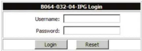
text_image
B064-032-04-IPG Login Username: Password: Login ResetLog in using the default Username: administrator and Password: password. For security purposes, it is strongly recommended that you change these to a unique Username and Password. (See Changing the Super Administrator Login section for instructions.)
After you successfully log in, the Local Console Main Screen appears:
text_image
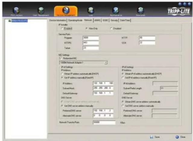
Port Setup User Management Service Settings List Maintenance Delete Connections | Hosts | Topics | User Preferences | Seconds | Access | PortConfiguration | PortNumber | PortName | DeviceName | Status 01 02 03 04 05 06 07 08 09 10 11 12 13 14 15 16 COMERICK & PINCES Options ©2010 Copyright © Right Reserved. TRIPP-LITE- Click the Device Management icon at the top of the screen.
- On the screen that appears on the right-hand side of the page select the Network tab.
text_image
TRIPP-LITE File Access User Management Device Information Operating Mode Network AVERAGE BVERAGE Security Data/Time IP Provider Enabling View Our Enabled Service Provider Program: 1000 HTTP: 80 HTTP: 443 USB: 22 Subnet: 23 HIC Settings StandardHIC 100bit Network Adapter 1 IP-Path Settings IP Address: Dset IP Address automatically (DHCP) Set IP Address manually (Fixed IP) IP Address: 192.168.1.182 Subset Mask: 255.255.255.6 Default Gateway: 192.168.1.1 DNS Server: Dset DNS server address manually Set DNS server address manually Preferred DNS server: 192.168.1.2 Alternate DNS server: 0.0.0.0 Network Transfer Plans: 99999 IP-Path Settings IP Address: Dset IP-Path address automatically (DHCP) Set IP-Path address manually (Fixed IP) IP-Address: Subset Packet Length: Subnet Gateway: DNS Server: Dset DNS server address automatically Set DNS server address manually Preferred DNS server: Alternate DNS server: Save CloseSuper Administrator Setup (continued)
Network Setup - IP Address Determination (continued)
NIC Settings
The B064-Series KVM Switch has two network interfaces. The NIC Setting section of the Network tab allows you to assign a single IP Address and DNS Server for both network interfaces, or to assign a separate address for each.
Redundant NIC
If Redundant NIC is enabled (the default), both interfaces use the IP address assigned to Network Adapter 1. Under this configuration, the B064-Series KVM Switch will switch to the second network interface in the event there is a crash on the first network interface.
- If you select Redundant NIC, the Network Interface drop-down menu will be frozen to Network Adapter 1, and you will only have to enter IP Address and DNS Server settings once.
- If you do not select Redundant NIC, you will have to enter IP Address and DNS Server settings for both Network Adapter 1 and Network Adapter 2. User the Network Interface drop-down menu to select the Network Adapter you want to configure.
IP Address and DNS Server Address
The B064-Series KVM switch supports both IPv4 and IPv6 addresses. The Network page allows you to set the IP address manually, or to select to have it automatically assigned via DHCP server. By default, the IP address is set to be assigned automatically via DHCP server.
• To have the IP address assigned by your DHCP server, check the Obtain IP address automatically check box in the IPv4 or IPv6 settings section, depending on your network.
- To assign an IP address yourself, check the Set IP address manually check box in the IPv4 or IPv6 settings section, depending on your network. When checked, the IP address and DNS server address fields open up, allowing you to enter in the desired settings. Once you have entered in all the IP address and DNS server address information, click the Save button at the bottom of the screen. Upon logging out of the KVM (click the Logout icon in the upper-right corner of the OSD), the KVM will reset itself and the IP address settings you just entered will be implemented.
Note: When manually assigning a DNS Server address, it is required that you enter the Preferred DNS server, but the Alternate DNS server is an optional field.
See Network section under Device Management for more information on these settings.
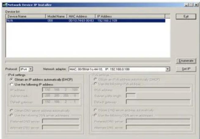
2. IP Installer
For computers running Windows, an IP address can be assigned with the IP Installer utility:
Note: In order to use the IP Installer, the IP Installer Enabled check box in the Network page must be checked. (See Network section under Device Management in OSD Operation for details.) By default, the IP Installer View Only check box is checked, allowing you to view the KVMs IP Address using the IP Installer but not change it.
text_image
Network Device IP Installer Device list: Device Name Model Name MAC Address IP Address N/A 000 00-10-7461 00:83 192.168.2.109 Protocol: IPv4 Network adapter: MAC 00:5044-10-44-10, IP: 192.168.0.188 IPv4 settings Obtain an IP address automatically (DHCP) Use the following IP address: IP address 192 168 2 100 Subnet mask 205 205 205 0 Default gateway 192 168 2 1 Obtain DNS server address automatically Use the following DNS server addresses: Preferred DNS server: Alternate DNS server: IPv4 settings Obtain an IPv4 address automatically (DHCP) Use the following IPv4 address: IPv4 address: Subnet ports length: Default gateway: Obtain DNS server address automatically Use the following DNS server addresses: Preferred DNS server: Alternate DNS server: Estimate Set IP-
Obtain the IP Installer file from the CD that came with the B064-Series KVM Switch and save it to a desired location on a computer that is on the same network as your B064-Series KVM Switch.
-
Go to the IP Installer file that you just saved and run the IPIstaller.exe file.
-
Select the B064-Series KVM Switch in the Device List.
Note: If the list is empty, or your device doesn't appear, click Enumerate to refresh the Device List. If there is more than one device in the list, use the MAC address to pick the one you want. The B064-Series KVM Switches MAC address is located on its bottom panel.
-
From here you can choose to Obtain an IP address automatically (DHCP), or Specify an IP address. If you choose to assign your own address, fill in the IP Address, Subnet Mask, and Gateway fields with information appropriate to your network.
-
Click Set IP.
-
After the IP address shows up in the Device List, click Exit.
3. Browser
By default, the KVM switch is set to have its IP address assigned automatically via DHCP server. If the KVM is connected to a network without a DHCP server, it boots with a default IP address. On IPv4 networks, the default IP is 192.168.0.60. If the KVM is on an IPv6 network, the default IP address is determined by the KVMs MAC address. For example, if the KVM has a MAC address of 00-10-74-13-81-01, the IPv6 address is FE80:0:0:0:0010:74FF:FE13:8101. The parts of the IP address that are bolded and underlined are fixed.
-
Access the B064-Series KVM switch by using the default URL mentioned above.
-
Assign a fixed IP address for the KVM using the same instructions as described in the Local Console section of this chapter.
Super Administrator Setup (continued)
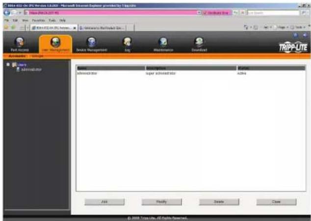
Changing the Super Administrator Login
To change the default Super Administrator Username and Password, do the following:
- At the top of the OSD page, click User Management.
Since this is the first time the page is being accessed, only the Super Administrator appears:
text_image
BSS-432-01.3% Version 1.0.200 - Microsoft Word Document Explorer provided by Trappolo File Edit View Tools Help New ISO on 3% format... Importing to Web Product Box... Full access Edit Management Device Management Log Maintenance Download TRIPP-LTE Add Modify Delete Close Add Remove Super administrator Add © 2020 Tripp Lite, All Files Powered.- Click Administrator in the left panel; or, select Administrator in the central panel and click the Modify button at the bottom of the page.
The User Information page appears:
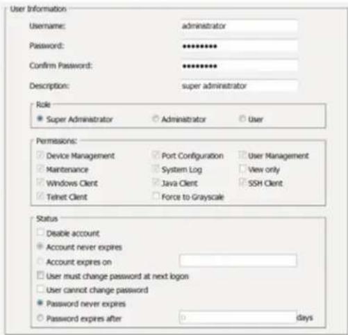
text_image
User Information Username: administrator Password: ********** Confirm Password: ********** Description: super administrator Role Super Administrator Administrator User Permissions: Device Management Port Configuration User Management Maintenance System Log View only Windows Client Java Client SSH Client Telnet Client Force to Grayscale Status Disable account Account never expires Account expires on User must change password at next logon User cannot change password Password never expires Password expires after 0 days- Change the Username and Password to something unique.
- Re-enter the password to confirm it is correct.
- Click Save.
- When the dialog box informing you that the change completed successfully appears, click OK.
Logging Into the B064-Series KVM Switch
The B064-Series KVM Switches can be accessed in the following ways: via local console, an internet browser, the AP Windows Client and/or the AP Java Client. Operating the KVM switch and configuring its settings is done the same regardless of how you connect to the B064-Series KVM Switch; the only difference is the way in which you establish the connection. This chapter describes the login procedures for each of these methods.
Local Console Login
The local console login dialog box is displayed once the installation is complete. Simply key in your Username and Password and click Login to bring up the OSD Main Page.
Note: If you supply an invalid login, the authentication routine will return an Invalid Username or Password message. If you see this message, log in again being careful to enter the correct Username and Password.
Logging Into the B064-Series KVM Switch (continued)
Browser Login
The B064-Series KVM Switches can be accessed via Internet browser from any platform that has the Java Runtime Environment 6, Update 3, or higher installed. If you don't already have the required JRE installed, it is available for free download from the Java web site: www.java.com
Note: Windows 7 users must run Internet Explorer as an administrator for the Active X control to work properly. If you don't run Internet Explorer as an administrator, you will not be able to access the connected computers.
To access the switch via browser, do the following:
- Open the browser and specify the IP address of the B064-Series KVM Switch you want to access, as given to you by your system administrator.
Note: For security purposes, a login string may have been set by the administrator. If so, you must include a forward slash and the login string along with the IP address when you log in. (For example, a computer with a login string of B064-032-04-IPG would have a URL such as 192.168.0.100/B064-032-04-IPG)
- When you try to log into the device from your browser, a Security Alert message appears to inform you that the device's certificate is not trusted, and asks if you want to proceed. The certificate can be trusted, but the alert is triggered because the certificate's name is not found on Microsoft's list of Trusted Authorities.
You have two options:
- If you are working on a computer other than your own, accept the certificate for just this session by clicking Yes.
- If you are working at your own computer, install the certificate. After the certificate is installed, it will be recognized as trusted. To install the certificate, do the following:
a) In the Security Alert dialog box, click View Certificate. The Certificate Information dialog box appears.
Note: You may need to run Internet Explorer as an Administrator in order to view and install the certificate.
b) Click Install Certificate.
c) Follow the Installation Wizard to complete the installation. Unless you have a specific reason to choose otherwise, accept the default options.
d) When the Wizard presents a caution screen, click Yes.
e) Click Finish to complete the installation and click OK to close the dialog box. The certificate is now trusted.
Upon installing the certificate or accepting the unrecognized certificate for the current session, the browser login dialog box appears.
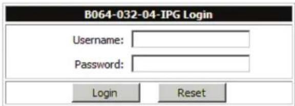
text_image
B064-032-04-IPG Login Username: Password: Login Reset- Provide a valid Username and Password (set by the KVM switch's administrator), and click Login to bring up the OSD Main Page.
Note: If you supply an invalid login, the authentication routine will return an Invalid Username or Password message. If you see this message, log in again being careful to enter the correct Username and Password.
AP Windows Client Login
In some cases, the Administrator may not want the B064-Series KVM Switches to be available via browser. The Windows AP Client allows Windows systems users access to the KVM switch without having to go through a browser.
The AP Windows Client can be found in the Download Section of the OSD or on the CD that came with your B064-Series KVM Switch. If you do not have access to the CD, and browser access to the KVM switch has already been disabled, you will need to obtain the file from your system administrator. Once you have saved the AP Windows Client, go to its location and double-click the WinClient.exe icon to bring up the Windows Client Connection Screen.
Note:
-
If you have trouble opening the AP Windows Client, save it to your desktop and try again.
-
When accessing the AP Windows Client for the first time, you will be prompted to provide a serial number. This serial number can be found on the CD that came with your KVM.
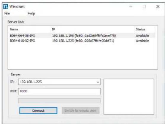
text_image
77 Winclient File Help Server List: Name IP Status BOE4-064-08-IPG 192.168.1.195 (fe80::3ad2:e69ff:fe2e:ef75) Available BOE4-015-02-IPG 192.168.1.225 (fc80::20g:67ff:fc00:bf71) Available Server: IP: 192.168.1.225 Port: 9000 Connect Switch to remote viewLogging Into the B064-Series KVM Switch (continued)
AP Windows Client Login (continued)
The Connection Screen
A description of the contents of the Connection Screen is given in the following table:
| Item Description | |
| Menu Bar | The Menu Bar contains two menus; File and Help. The File Menu allows the operator to Create, Save, and Open Work files. |
| Server List | Each time the WinClient.exe file is run, it searches the User's LAN segment for B064-Series KVM Switches, and lists the ones it finds in this box. Double-click on any of the units in this list to connect to it.Note: For a switch to show up in the Server List, the Enable Device List check box in the Operating Mode page (see Operating Mode section under Device Management in OSD Operation for details) must be checked and the Program service port in the Network page (see Network section under Device Management in OSD Operation for details) must be set to the same number as in the AP Windows Client Port field. |
| Server | This area is used when you want to connect to a B064-Series KVM Switch at a remote location.• Click on the IP drop-down and select an address from the list. If the address you want is not listed, key in the target IP address in the IP field, and its port number in the Port field.• When the IP address and port number have been specified, click Connect to bring up a login dialog box. Provide a Username and Password as provided by your system administrator and click OK to establish a connection with the B064-Series KVM Switch.• When you have finished with your session, click Disconnect to end the connection. |
| Message List Lists | status messages regarding the connection to the B064-Series KVM Switch. |
| Switch to Remote View | Once a remote connection with a B064-Series KVM Switch has been established, this button becomes active. Click it to switch to the KVM Switch's Main OSD Page. |
The File Menu
The File Menu allows the operator to Create, Save, and Open Work Files. A Work File consists of all the information specified in a Client session. This includes the items in the Server List and Server IP List.
Whenever a user runs the Client program, it opens with the values contained in the current Work File, i.e. the values that were in effect when the program was last closed.
The File menu consists of three items:
| Item Description | |
| New | Allows the user to create a named work file so that its values will not be lost and will be available for future use |
| Open Allows the user to open a previously saved work file and use the values contained in it | |
| Save Allows the user to save the values presently in effect as the current work file | |
| Exit Exits the AP Windows Client | |
AP Java Client Login
In those cases in which the Administrator does not want the B064-Series KVM Switch to be available via browser and the remote user is not running Windows, the AP Java Client provides access to the KVM switch.
After downloading the AP Java Client, go to the location on your hard disk where you downloaded the program and double-click on it to bring up the connection screen. The AP Java Client connection screen is the same as the Windows version, except that it does not contain a menu bar with File and Help menus. Note: When accessing the AP Java Client for the first time, you will be prompted to provide a serial number. This serial number can be found on the CD that came with your KVM.
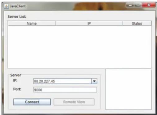
text_image
JavaClient Server List: Name IP Status Server IP: 68.20.227.45 Port: 9000 Connect Remote View- If your KVM is displayed in the Server List, connect to it by highlighting it and clicking on the Connect button. Note: For a switch to show up in the Server List, the Enable Device List checkbox in the Operating Mode page (see Operating Mode section under Device Management in OSD Operation for details for details) must be checked and the Program server port must match what is set in the Network page (See Network section under Device Management in OSD Operation for details.)
- If your KVM does not display in the Server List, enter in its IP address in the IP server field and click the Connect button.
- Upon clicking the connect button, you will be prompted to enter your username and password. Enter in your username and password and press OK.
- When connected, the Remote View button will be activated. Click on it to access the KVM remotely. Click on the Disconnect button to log out of the KVM switch.
OSD Operation
The OSD Main Page
After logging into the KVM switch, the OSD Main Page appears. Depending on how you logged into the switch, the interface will vary slightly. The following section describes the differences between these interfaces and the icons and functions you will find in them.
Web Browser Main Page
When logging into the KVM switch via web browser, the following page is displayed.
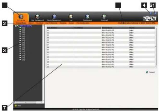
text_image
Port History User Management Device Management Log Maintenance Download TRIPP-LTE Description Name Layout Test Properties Structure Notes TestConfiguration #3. admin/analysis, welcome to TRIPP-LTE 61.02.2PG File Edit View Tools Help 03 B94-016-02-PG Online 02 B94-016-02-PG Online 03 B94-016-02-PG Online 04 B94-016-02-PG Online 05 B94-016-02-PG Online 06 B94-016-02-PG Online 07 B94-016-02-PG Online 08 B94-016-02-PG Online 09 B94-016-02-PG Online 10 B94-016-02-PG Online 11 B94-016-02-PG Online 12 B94-016-02-PG Online 13 B94-016-02-PG Online 14 B94-016-02-PG Online 15 B94-016-02-PG Online 16 B94-016-02-PG Online ConnectThe following chart describes the components of this page.
| No. Component Description | ||
| 1 | Tab Bar | The Tab Bar consists of category icons that take you to the various interfaces used to operate the KVM switch. The icons that are displayed in the Tab Bar depend on your user type (Super Administrator, Administrator, User), your permissions and the method you use to log into the KVM switch. |
| 2 | Menu Bar | The Menu Bar consists of sub-categories of the selected category icon. As with the Tab Bar, the sub-categories that show up in the Menu Bar depend on your user type and permissions. |
| 3 | Sidebar | The Sidebar displays a Tree Diagram that lists all of the functions available for the chosen category and sub-category. Clicking on one of the Sidebar functions will pull up the corresponding interface in the Interactive Display Panel. At the bottom of the Sidebar is a Filter button that allows you to display only the parts of the Tree Diagram that you filter for. (See Filter section under Connections in OSD Operation for details.) |
| 4 | About | Clicking on this icon pulls up the KVM switches firmware version |
| 5 | Logout | Clicking on this icon logs you out of the KVM switch |
| 6 | Welcome Message | When enabled (see User Preferences section under OSD Operation for details), this section of the main page will display a welcome message. This is disabled by default. |
| 7 | Interactive Display Panel | This is the main work area of the OSD. Different interfaces are displayed here depending on your category, sub-category and sidebar selections. |
AP Client Main Page
When logging into the KVM switch via the non-browser AP Windows or Java client, the following page is displayed.
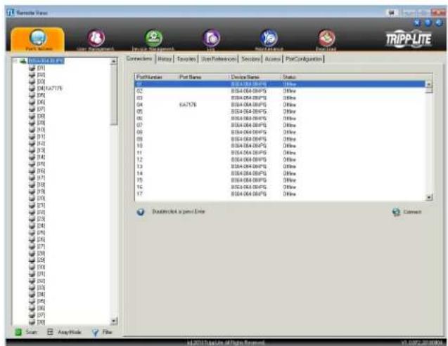
text_image
TRIPP-LITE PortNumber Port Name Device Name Status 01 BSSA-064.06/PS 01/xx 02 BSSA-064.06/PS 01/xx 03 BSSA-064.06/PS 01/xx 04 BSSA-064.06/PS 01/xx 05 BSSA-064.06/PS 01/xx 06 BSSA-064.06/PS 01/xx 07 BSSA-064.06/PS 01/xx 08 BSSA-064.06/PS 01/xx 09 BSSA-064.06/PS 01/xx 10 BSSA-064.06/PS 01/xx 11 BSSA-064.06/PS 01/xx 12 BSSA-064.06/PS 01/xx 13 BSSA-064.06/PS 01/xx 14 BSSA-064.06/PS 01/xx 15 BSSA-064.06/PS 01/xx 16 BSSA-064.06/PS 01/xx 17 BSSA-064.06/PS 01/xx Dustorrect a port line Connect File: https://2013.duplink.org/nspn-nmwn/ ISSN: 2013@2013@2013The AP Client Main Page differs from the Web Browser Main Page as follows:
- Instead of a Menu Bar, the AP Client Main Page has a set of notebook tabs that are used to select sub-categories. As with the Web Browser Main Page, the notebook tabs displayed depend on the user type and permissions.
- In addition to the Filter button at the bottom of the Sidebar, there is a Scan button and an Array Mode button.
- There is a hidden Control Panel (see Control Panel section under Remote Session Operation for details) at the upper center of the screen that becomes visible when you mouse over it.
- In addition to the two icons in the upper-right corner of the Web Browser Main Page, there is a third icon that closes the OSD and displays the screen of the last selected port.
The OSD can be navigated via keyboard using the commands in the table below:
| Command Description | |
| Ctrl + P Opens the Port Access category page | |
| Ctrl + U Opens the User Management category page | |
| Ctrl + C Opens the Device Management category page | |
| Ctrl + L Opens the Log category page | |
| Ctrl + M Opens the Maintenance category page | |
| Ctrl + D Opens the Download category page | |
| F1 Displays the KVM switches firmware version | |
| F2 Press to edit the name of the selected port | |
| F4 Selects the Sidebar panel | |
| F5 Selects the Interactive Display Panel | |
| F7 | Closes the OSD and displays the screen of the last selected port |
| F8 Logs you out of the KVM switch | |
OSD Operation (continued)
The OSD Main Page (continued)
Local Console Main Page
The Local Console Main Page is the same as the AP Client Main Page except that the Downloads icon in the tab bar is not available.
OSD Tab Bar
The number and type of icons that appear on the tab bar at the top of the page are determined by user type (Super Administrator, Administrator or User) and the permissions assigned when the account was created. The functions associated with each of the icons are explained in the following table:
| Icon Description | |
 | Port Access: This page is used to access and control the devices on the KVM switch installation. This page is available to all users. |
 | User Management: This page is used to create and manage Users and Groups, and to assign devices to them. This page is available to Super Administrator and Administrators, ordinary users will not have access to it. |
 | Device Management: This page is used by the Super Administrator to configure and control the overall operation of the KVM switch. This page is available to Super Administrators or Administrators/Users who have been given access. |
 | Log: This page displays the contents of the log file. (See Log section under OSD Operation for details.) |
 | Maintenance: This page is used to install new versions of the B064-Series KVM Switch firmware. This page is available to Super Administrators or Administrators/Users who have been given access. |
 | Download: Users with appropriate permission can click this icon to download the AP Windows Client, the AP Java Client and the Log Server. This page is available to all users, although what downloads a User can access is determined by the Super Administrator or Administrator. Note: The Download icon is not available via the local console. |
There are three small icons in the upper right-hand corner of the page. Their functions are described in the following table:
| Icon Description | |
 | Click this icon to close the OSD page and return to the display of the last selected port.Note: This icon is not available in the Web Browser Main Page. |
 | Click this icon to display the firmware version of the B064-Series KVM Switch. |
 | Click this icon to log out and end your B064-Series KVM Switch session. |
Port Access
The Port Access section of the OSD is where users can access KVM ports, and control settings that directly affect that access. The sub-sections contained in the Port Access section are described in the pages that follow.
OSD Operation (continued)
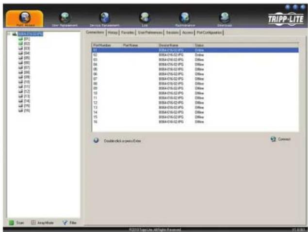
Connections
The OSD Main page is the same screen that you get when navigating to the Connections sub-section of the Port Access section. From this page you can connect to the KVM ports.
All switches and their ports, including cascaded KVM switches, are listed in a tree structure in the panel at the left of the screen:
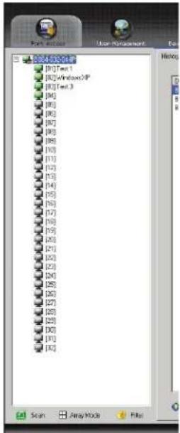
text_image
New User Control User Management [0] [1] Text 1 [0] [2] WindowsXP [0] [3] Text 3 [0] [4] [0] [5] [0] [6] [0] [7] [0] [8] [0] [9] [10] [11] [12] [13] [14] [15] [16] [17] [18] [19] [20] [21] [22] [23] [24] [25] [26] [27] [28] [29] [30] [31] [32]When accessing a port for the first time via web browser, users will experience a series of prompts:
Internet Explorer
When logging onto the KVM switch via Internet Explorer, the default viewer is the Windows ActiveX viewer. To use the Java Viewer when accessing the KVM switch via Internet Explorer, you need to update the Viewer setting in the User Preferences page (See User Preferences section under OSD Operation for details).
Note: Windows 7 users must run Internet Explorer as an administrator for the Active X control to work properly. If you don't run Internet Explore as an administrator, you will not be able to access the connected computers.
- When using the Windows ActiveX Viewer and clicking on a port for the first time, a screen will open up and you will be prompted to install the Windows ActiveX control. Click on the prompt and choose to install the ActiveX control. Note: The screen that opens up may display a page that says the web pages certificate can not be trusted. If this is the case, click on the option to continue to the web page anyway.
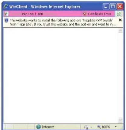
text_image
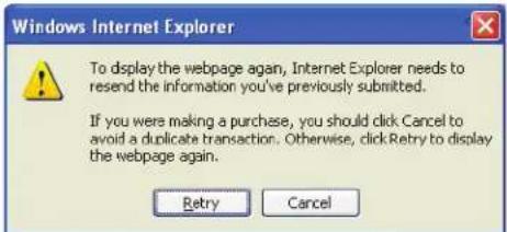
WinClient - Windows Internet Explorer 192.158.1.180 Certificate Error This website wants to install the following add-on: 'TripLite KVM Switch' from 'TripLite . If you trust the website and the add on and want to in...'- When you install the ActiveX control, you may be prompted to resend the information in order to display the web page. Click Retry.
text_image
Windows Internet Explorer To display the webpage again, Internet Explorer needs to resend the information you've previously submitted. If you were making a purchase, you should click Cancel to avoid a duplicate transaction. Otherwise, clickRetry to display the webpage again. Retry Cancel- Lastly, you will be prompted to install the software. Click Install.
text_image
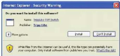
Internet Explorer - Security Warning Do you want to install this software? Name: TripLite VM Switch Publisher: TripLite More options Install Don't Install While files from the Internet can be useful, this file type can potentially harm your computer. Only install software from publishers you trust. What's the risk?Non-Windows Browser
When using a non-Windows browser, you will automatically be connected to remote computers using the Java Viewer.
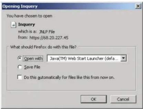
- When clicking on a port for the first time, you will be prompted to run the Java Viewer. Click ok. (To avoid this prompt every time you access a port, check the checkbox next to Do this automatically for files like this from now on.)
text_image
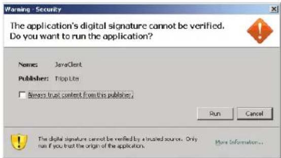
Opening Inquiry You have chosen to open Inquiry which is a: JNLP File from: https://68.20.227.45 What should Firefox do with this file? Open with Java(TM) Web Start Launcher (defa... Save File Do this automatically for files like this from now on. OK Cancel- You will then be prompted to run the Java Viewer, and trust the publisher (Tripp Lite). Click Run.
text_image
Warning - Security The application's digital signature cannot be verified. Do you want to run the application? Name: JavaClient Publisher: TripLite □ Always trust content from this publisher. Run Cancel The digital signature cannot be verified by a trusted source. Only run if you trust the origin of the application.OSD Operation (continued)
Connections (continued)
The Port Selection List
- Users only see the switches and ports they have been given access to.
- Ports and cascaded KVM switches are located under their parent switches. Click the Plus (+) in front of a switch to expand the tree and see the ports underneath it.
Note: In order for a cascaded B064-016 to show up as an expandable KVM in the port list, you must use a PS/2 SIU to cascade it from the first-level KVM. If you use a USB SIU, it will be displayed as an ordinary port, and you will have to use the B064-016 OSD to access computers/servers connected to it.
- When expanded, there is a Minus (-) before the KVM's device name. Click the Minus (-) to collapse the tree and hide the ports.
- A port's ID number is displayed in brackets next to the port icon. For convenience, you can give each port a unique name in addition to this ID.
- KVM switches and ports that are on line have their monitor screen icons lit green. The monitor screens are gray for devices and ports that are offline.
Port Configuration
When accessing the KVM via AP Windows or Java Client, right-click on any port in the Sidebar to configure a connected computer or switch. (This feature is not available when accessing the OSD via web browser.) A list with options pops up. Listed items vary depending on user type and whether a cascaded KVM switch or a computer/server port was selected. Available configuration items are:
Collapse
Rename
Copy
Properties
Item Access Type Description
| Expand/ Collapse Super Administrators, Administrators and Users | ·If the device's ports are not displayed, the dialog box entry is Expand. Click Expand to open the tree and display the ports.·If the device's ports are displayed, the dialog box entry is Collapse. Click Collapse to close the tree view.Note: This item is only active for KVM switches that have child devices connected to them. This has the same effect as clicking the Plus (+) or Minus (-) in the tree view. |
| Rename Super Administrators, Administrators and Users | For convenience, especially in large installations with many switches and ports, each port can be given a unique name. Note: Administrators and Users must be given configuration access to a KVM or computer port to be able to edit the port name. (See Device Assignment section under User Management in OSD Operation for details.) |
| Copy Super Administrators, Administrators and Users | This item is only available for ports with computers/servers connected to them. It is used when creating a Favorites bookmark. (See Adding a Favorite section under Favorites in OSD Operation for details.) |
| Properties Super Administrators and Administrators This item allows you to configure the properties of the port.·For the master KVM switch, clicking this item takes you to the Device Management page.·For ports with computers/servers connected to them, a dialog box opens allowing you to update the properties for the connected computer/server. (See Port Properties section under Connections in OSD Operation for details.) | |
Port Naming
For convenience, especially in large installations with many KVM switches and ports, each port can be given a unique name. To assign, modify or delete a port name, follow the instructions below. Note: Administrators and Users must be given configuration access to a KVM or computer port to be able to edit the port name. (See Device Assignment section under User Management in OSD Operation for details.)
- Click once on the port you want to edit to highlight it, wait one second and click on it again. Note: This is not a double-click; it involves two separate clicks. Double-clicking will switch you to the device attached to the port.
You can also right-click on the port you want to edit and select Rename in the popup box that appears (non-browser clients only).
After a second or two, the display changes to provide a text input box.
- Key in a name for the port (or change/delete a previous one). The maximum number of characters allowed for a port name is 20. You can use any combination of letters, numbers, and symbols on the typewriter keys of keyboards with PC US English layout.
- When you have finished editing the port name, press [Enter] or click anywhere outside of the input box to complete the operation.
OSD Operation (continued)
Connections (continued)
Port Properties
Users accessing the KVM via the non-browser clients can right-click on a computer/server port and select Properties to configure that port's settings. The settings that can be changed via this dialog box are listed in the chart below.
Note: These settings can also be changed via the Port Configuration page. (See the Port Configuration section under OSD Operation for details.)
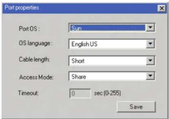
text_image
Port properties Port OS: Sun OS language: English US Cable length: Short Access Mode: Share Timeout: 0 sec (0-255) Save| Field Description | |
| Port OS Specifies the operating system for the computer/server connected to the port. Choices are Windows, Mac, Sun, and Other. The default is Windows. | |
| OS Language | Specifies the operating system language being used by the computer connected to the port. Click on the drop-down list to choose from a number of languages. The default is English US. |
| Cable Length | Specifies the length of the Cat5e cable that is being used to connect the computer to the port. Because the quality of video decreases when using longer cable, the B064-Series KVM Switch will make adjustments to improve the video quality based on this setting. Choices are Short (less than 32 ft.), Medium (32-82 ft.), and Long (greater than 82 ft.). The default is Short. |
| Access Mode | Access Mode defines how the port is to be accessed when multiple users are logged on. Choices are Exclusive, Occupy, and Share. |
| Exclusive: The first user to switch to the port has exclusive control over the port. No other users can view the port. The Timeout function does not apply to ports which have this setting. | |
| Occupy: The first user to switch to the port has control over the port. However, additional users may view the port's video display. If the user who controls the port is inactive for longer than the time set in the Timeout box, port control is transferred to the next user to move the mouse or strike the keyboard. | |
| Share: Users simultaneously share control over the port. Input from the users is placed in a queue and executed chronologically. Under these circumstances, users can take advantage of the Message Board. The message board allows the user to manually take control of the keyboard and mouse only, or of the keyboard, mouse and video of a Share port. (See Message Board section under Control Panel in Remote Session Operation for details.) | |
| Timeout | This field displays the timeout value that is set for all ports in the installation. When the port's Access Mode has been set to Occupy, if there is no activity from the user occupying the port for the amount of time set here, the user is timed out and the port is released. The first user to send keyboard or mouse input after the port has been released gets to occupy the port. As this setting is the same for all ports, you are not allowed to configure it on a port-by-port basis. This setting can be changed using the Port Properties dialog box for the master KVM switch, which is discussed in the Port Properties section. |
After making your configuration choices, click Save to save your new settings and close the dialog box.
OSD Operation (continued)
Connections (continued)

Scan
Scan
The Scan function automatically switches among all the ports accessible to the logged-on user at regular intervals, allowing their activity to be monitored automatically. (See Auto Scanning section under Remote Session Operation for details.) Note: The Scan icon will not appear when accessing the KVM switch via web browser.

ay Mode
Panel Array Mode
Panel Array Mode also permits port activity to be monitored automatically. The screen displays a grid of panels, each representing a port on the installation. Only ports that are on line and user accessible are displayed. Off-line or non-accessible ports are left blank. (See Panel Array Mode section under The OSD Toolbar in Remote Session Operation for details.)

Filter
Filter
Filter allows you to control which ports are displayed in the Port Selection List, as well as which ports are scanned when Auto Scan Mode is invoked. When you click Filter, the bottom of the panel changes to look similar to the figure, below:
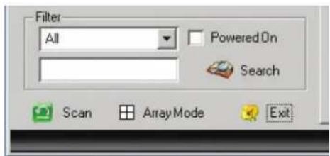
text_image
Filter All Powered On Search Scan Array Mode ExitAll - with no other filter options selected, lists all of the ports on the installation.
- Putting a check mark in the Powered On checkbox lists only the ports that have their attached devices powered on.
- The text input box and Search button allow you to key in a search string so that only port names that match what you key in show up in the list.
Interactive Display Panel
The Connections sub-section will display port status information on the Device Level and port connection and configuration options at the Port Level.
Device Level
When a KVM switch is selected in the Sidebar tree, the Connections sub-section will display a list of the ports that are accessible to the logged-on user.

OSD Operation (continued)
Connections (continued)
The chart below describes the attributes that are listed for each port.
| Attribute Description | |
| Port Number The KVM switch port that the computer or KVM is connected to | |
| Port Name If a port is assigned a name, it is displayed here | |
| Device Name The name of the KVM switch that the port is on | |
| Status Current status of the computer or KVM connected to the port; Online or Offline | |
| Connect | A Connect icon will be located underneath the port list. Highlight a port and click Connect to open up a remote session with the selected port displayed. |
Note: When accessing the KVM via web browser, this page can be sorted by any attribute by clicking on the column header.
Port Level
When a port is selected in the Sidebar tree, the Connections subsection will display port connection and configuration options.
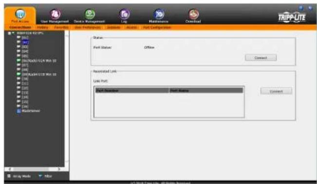
text_image
Port Active User Management Service Management Log Maintenance Download Connection History Favorites Port Preferences Settings Actions Port Configuration Start Port Start Port Status Offline Connect Accessed Link Link Port Start Direction Start Name Connect TrIPP-LITE Start Port (Up to 10) Start Port (Up to 10) Start Port (Up to 10) Start Port (Up to 10) Start Port (Up to 10) Start Port (Up to 10) Start Port (Up to 10) Start Port (Up to 10) Start Port (Up to 10) Start Port (Up to 10) Start Port (Up to 10) Start Port (Up to 10) End PortThe chart below describes the sections that are displayed on this page.
| Section Description | |
| Status | This displays the Port Status; whether it is online or offline, and whether virtual media can be mounted to it. Click on the Connect button to open a remote session with the selected port displayed. |
| Associated Link | Each port can have additional ports associated with it, so that the user can access multiple ports via one connection page. Associated Links can be added/removed from the Port Configuration sub-section (see Port Configuration section under OSD Operation for details). When ports are available in the Associated Link section, simply highlight one and click the Connect button to open a remote session with that port displayed. |
History
The History page provides a record of each time that a port was accessed.
- If there are more entries than there is room on the screen, a scroll bar appears to let you scroll up and down to see the entire record.
• To clear the records and start over, click the Clear History button at the bottom right corner of the page.
Note: You can access a port in the History page by double clicking it, or highlighting it and pressing [Enter]. When accessing the KVM switch via web browser, you can sort the results by clicking on any of the column headers.
OSD Operation (continued)
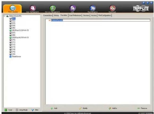
Favorites
Favorites is similar to a bookmarks feature. Frequently visited ports can be listed on this page. Open this page and select the port instead of searching for it in the tree view. This feature is especially useful for larger, cascaded installations. Note: Each Favorites bookmark that you create is a folder in which multiple ports can be saved.
Adding a Favorite
To add a port to Favorites, do the following:
- Right click in the main panel and click on the Add Favorite option that appears. An entry appears named Untitled Favorite.
text_image
Port Resource User Resources Service Management User Resources Transportation System TRIPP-LITE B064-015-GCPG [1] [2] [3] [4] [5] [6] [7] [8] [9] [10] [11] [12] [13] [14] [15] [16] [17] [18] [19] [20] [21] [22] [23] [24] [25] [26] [27] [28] [29] [30] [31] [32] [33] [34] [35] [36] [37] [38] [39] [40] [41] [42] [43] [44] [45] [46] [47] [48] [49] [50] [51] [52] [53] [54] [55] [56] [57] [58] [59] [60] [61] [62] [63] [64] [65] [66] [67] [68] [69] [70] [71] [72] [73] [74] [75] [76] [77] [78] [79] [80] [81] [82] [83] [84] [85] [86] [87] [88] [89] [90] [91] [92] [93] [94] [95] [96] [97] [98] [99] File Region Edit-Programs Scan Audio Mode Spin Add Modify Add/Win Remove © 2018 E-mail: AR/Bigri Research VU 0072-20180000-
Click inside the text entry box to erase Untitled Favorite and key in the desired name.
-
To add a port, drag it from the Port Select list and drop it into the Favorites bookmark you just created. You can also add a port by right-clicking on it and selecting Copy. After copying, right-click on the Favorites bookmark and select Paste. The KVM switch the port is connected to goes into the Favorites bookmark along with the port. The port is located under the switch, as it would be in the tree view on the left-hand panel.
Note: Right-clicking on a port that is already in a Favorites bookmark will give you the option to cut the port out of that bookmark and paste it into another Favorites bookmark.
- Repeat step 3 for any other ports you want to add to your Favorites bookmark.
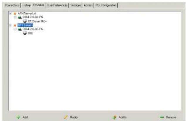
text_image
Connections | History | Favorites | Use Preferences | Sections | Access | Port Configuration ATM Server List 0964 016/02:IPG [01]Server 053+ 01.1 Server 0964 016/02:IPG [00] Add Modify Add to RemoveModifying a Favorite
To modify a Favorites bookmark, right-click on it and select one of the options from the pop-up menu that appears. The menu that appears allows you to perform the following options:
Collapse/Expand – As with the tree view on the right-hand side of the page, this option allows you to either collapse or expand the Favorites bookmark and all of its included ports
Add Favorite – Select this option to create a new Favorites bookmark Delete – Select this option to delete the selected Favorites bookmark
Rename - Select this option to change the name of the Favorite bookmark
Copy - Select this option to copy all of the Favorites bookmark's contents, in order to paste them into another Favorites bookmark
Paste – Select this option to paste copied ports into the selected Favorites bookmark
Note: Right-clicking on a port that is already in a Favorites bookmark will give you the option to Cut the port out of that bookmark and paste it into another Favorites bookmark.
OSD Operation (continued)
User Preferences
The User Preferences page allows users to set up their own individual working environments. The B064-Series KVM Switch stores a separate record for each user profile, and sets up the working environment according to the Username that was used to access the KVM switch. Note: The User Preferences page is different on the Web Browser version than the AP Client version. The AP Client version does not include the password, Viewer or Welcome Screen option.
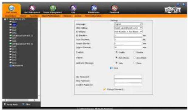
text_image
TRIPP-LITE Network: New Management Gaze Management Log Maintenance Connected Network: New Services: New User Preferences: New Services: Second Configuration Settings Language: 0000000000000000000000000000000000000000000000000000000000000000000000000000000000000000000000000000 Network History: 8D Display: 8D Duration: 5 Size Deviation: 5 Current Border: 5 Legend Forward: 45 Default: Enable Auto-Detect Save Cloud Welcome: None Auto New Password: Custom Password: Change Password...The page settings are explained in the following table:
Setting Description
| Language | Selects the language that the interface displays in. Options are English (default), Spanish, French, German, Russian, Italian, Japanese, Korean, traditional Chinese and simplified Chinese. |
| OSD Hotkey | Selects which hotkey controls the OSD function. You can choose from the following options; [Scroll Lock] [Scroll Lock], [Ctrl] [Ctrl], [Alt] [Alt], [Shift] [Shift] and [Print Screen] [Print Screen]. The default is [Scroll Lock] [Scroll Lock]. |
| ID Display | Selects how the Port ID is displayed: the Port Number alone (PORT NUMBER); the Port Name alone (PORT NAME); or the Port Number plus the Port Name (PORT NUMBER + PORT NAME). The default is PORT NUMBER + PORT NAME. |
| ID Duration | Determines how long a Port ID displays on the monitor after a port change has taken place. You can choose an amount from 1—255 seconds. The default is 3 seconds. A setting of 0 (zero) means the Port ID is always on. |
| Scan Duration | Determines how long the focus dwells on each port as it cycles through the selected ports in Auto Scan Mode. Key in a value from 1—255 seconds. The default is 5 seconds; a setting of 0 disables the Scan function. |
| Screen Blanker | If there is no input from the console for the amount of time set with this function, the screen is blanked. Key in a value from 1—30 minutes. A setting of 0 disables this function. The default is 0 (disabled). When the screen is blanked, simply moving the mouse over the screen will bring it back up. Note: This setting affects the monitor of the local console only. |
| Logout Timeout | If there is no user input for the amount of time set with this function, the user is automatically logged out. A login is needed before the B064-Series KVM Switch can be accessed again. The default is 30 minutes. |
| Toolbar | The Toolbar option allows you to enable/disable the OSD Toolbar. (See The OSD Toolbar section under Remote Session Operation for details.) As all of the features of the OSD Toolbar are available in the Control Panel, you may want to disable it. The default setting is enabled. |
| Viewer The Viewer option | is available only when accessing the KVM switch via web browser. It allows you to choose what viewer is used to access a port.Auto Detect – The KVM switch will automatically choose which viewer to use based on the web browser being used. The Windows Viewer will be used for Internet Explorer and the Java Viewer will be used for all other browsers.Java Client – The KVM switch will always use the Java Viewer, regardless of what browser is being used. |
| Welcome Message | The Welcome Message option is also available only to those who access the KVM switch via web browser. This allows you to show or hide the welcome message that appears in the upper-right corner of the screen. |
| Save | To apply any changes that you make, you must click the Save button before exiting. |
| Changing a Password | To change a password, you must enter in the old password and the new password. The new password will need to be entered twice for security purposes. Once typed in, click the Save button to apply the change. |
OSD Operation (continued)
Sessions
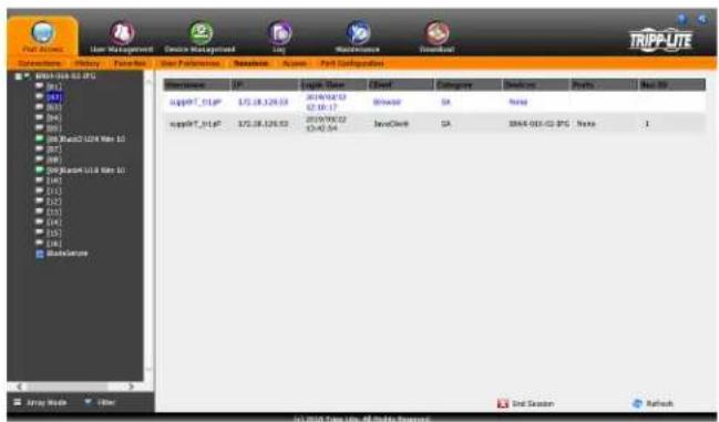
text_image
TRIPP-LTE User Management Device Management Log Maintenance Download Transaction: Summary Function User Preferences: Access - Port Configuration Description: IP Logist Name: Cheet Category: Document Paths: Real Site supplyT_01GP 375.08.126.03 2019/02/12 62.10.17 Apache SA None supplyT_01GP 375.08.126.03 2019/02/12 12:42:54 JavaClerk SA 2004-051-03-PSC Note 1 One Season RefreshThe Sessions sub-section allows Super Administrators and Administrators to see who is logged into the KVM switch, and provides information about each of their sessions. Super Administrators can see all accounts that are logged into the KVM, whereas Administrators are only able to see Administrator and User accounts.
It also provides the option of ending a session by selecting the account from the Sessions list and clicking the End Session icon. To refresh the Sessions list to display the most current information, click on the Refresh icon.
Note: The Sessions tab is only available for Super Administrators and Administrators. Users will not be able to access it.
Access
The Access sub-section allows Super Administrators and Administrators to set user/group access and configuration rights for switches and ports. As with the Sessions sub-section, Super Administrators can see all accounts, whereas Administrators can only see Administrator, User and Group accounts. The browser and non-browser Access sub-sections are the same, except the non-browser page includes drop-down filters above each column. These filters allow you to choose which accounts are displayed. For example, you can choose to display only those accounts that are given configuration access to the selected KVM/port by choosing the Permitted option from the drop-down menu above the configuration column. Note: The Access sub-section is not available to User accounts, and will not show up when they log into the OSD. The Access sub-section does not appear when a Blade Server is selected in the Sidebar tree.
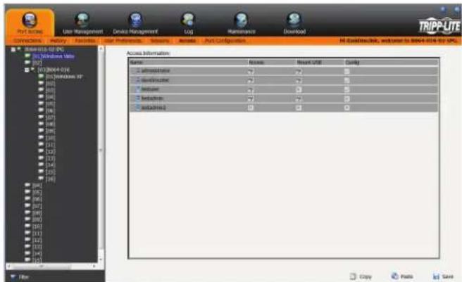
text_image
View Options User Management Device Management CGI Maintenance Overview1 TRIPP-UTE Access Information Name Access Reset unit Config Administrative Default Indicate Indicate Autoexecuted Copy Paste SaveWhen the master KVM switch is highlighted in the port list, the Access sub-section displays only one setting column; Config. When a port is highlighted in the port list, the Access sub-section displays three settings columns; Access, Mount USB and Config. The section that follows describes these settings, and how to edit them.
OSD Operation (continued)
Access (continued)
| Setting Description | |
| Access | The Access setting determines if an account is allowed to access the selected port, and if so, what level of access the account has. To edit this setting, click on the box in the Access column next to the account you wish to edit. Continue to click until you toggle to the desired setting.Full Access – This setting is represented by an icon that shows a pair of glasses and a pencil. It allows the corresponding account to both view video and perform operations on the selected port.View Only – This setting is represented by a pair of glasses only. It allows the corresponding account only to view video of the selected port.No Access – This setting is represented by an X, and denies the corresponding account access to the selected port. |
| Mount USB | The Mount USB setting determines if an account is allowed to access the virtual media functionality on the selected port, and if so, what level of access the account has. To edit this setting, click on the box in the Mount USB column next to the account you wish to edit. Continue to click until you toggle to the desired setting.Full Access – This setting is represented by an icon that shows a pair of glasses and a pencil. It allows the corresponding account to both read and write to virtual media mounted to the selected port.View Only – This setting is represented by a pair of glasses only. It allows the corresponding account only to read virtual media mounted to the selected port.No Access – This setting is represented by an X, and denies the corresponding account access to virtual media mounted to the selected port. |
| Config | The Config setting determines if an account has permission to make changes to the master KVM or port configuration settings. To edit this setting, click on the box in the Config column next to the account you wish to edit. Click to toggle Config access on/off. A check mark enables access, an X disables access. Note: Config checkboxes are provided as a way for Super Administrators and Administrators to customize which ports Administrators and User accounts have Configuration access to. In order for the Config checkbox to enable Configuration access to a port, the Administrator or User account must be given Port Configuration access to the KVM switch. (See Permissions in the Adding User Accounts section under User Management in OSD Operation for details.) |
When you are done editing access rights to the selected port, click on the Save icon in the lower-right corner of the Access sub-section.
Also at the bottom of the page are Copy and Paste icons. These are used to copy the access settings from one port and paste those same settings to another port. To do this, simply highlight the port you want to copy and click on the Copy icon. Then highlight the port you want to paste to and click the Paste icon.
Port Configuration
The Port Configuration sub-section allows Super Administrators and Administrators to edit port properties settings, assign system macros to a port, and add/remove associated links. When the master KVM is highlighted and the Port Configuration sub-section is selected, the following screen appears.
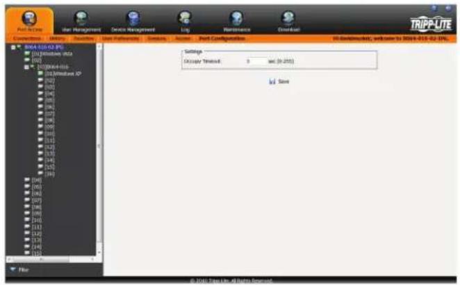
text_image
File Edit View User Management Devices Management Log Maintenance Control Description History Sources User Pathways Description Section Port Configurations All-Development, welcome to 2014-010-02-15% TRIPP-LTE 8064-010-02 (P) (0) Minimum v3a (0) 100000+01b (0) Minimum XP (0) (1) (2) (3) (4) (5) (6) (7) (8) (9) (10) (11) (12) (13) (14) (15) (16) (17) (18) (19) (20) (21) (22) (23) (24) (25) (26) (27) (28) (29) (30) (31) (32) (33) (34) (35) (36) (37) (38) (39) (40) (41) (42) (43) (44) (45) (46) (47) (48) (49) (50) (51) (52) (53) (54) (55) (56) (57) (58) (59) (60) (61) (62) (63) (64) (65) (66) (67) (68) (69) (70) (71) (72) (73) (74) (75) (76) (77) (78) (79) (80) Settings: Disaster Threshold: 3 and (0.255) id Save © 2014 Step 1.0 - All Rights ReservedThe only setting that appears on this page is the Occupy Timeout setting. This setting controls the amount of inactivity time before a port that is set to Occupy (see Port Property section on the following page for details) is opened for access by another user. Enter in a value from 0 to 255 seconds. The default is 3 seconds.
When a standard port is highlighted and the Port Configuration subsection is selected, a screen opens up that contains two sections; Port Property and Associated Link. The Port Property section is opened first by default.
OSD Operation (continued)
Port Configuration (continued)
Port Property
The Port Property page of this subsection lists status information about the selected port, and provides editable settings related to the connected computer and system macros. The contents of this page are described in the table below.
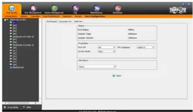
text_image
Port Setup User Management Device Management Maintenance Download TRIPP-LITE File Edit View Help Start Project: Interactive Link: Web-View Status: Port Status: Offline Adapter Type: Unknown Adapter Version: Unknown Properties: Port OS: none Active Media: None Off Marks: None Save Auto Mode Filter 00.0% 120000000000000000000000000000000000000000000000000000000000000000000000000000000000000000000000| Setting Description | |
| Status | Port Status – The status of the selected port is displayed here. If no computer/KVM is connected, or a computer/KVM is connected but not powered on, the port status will show up as Offline. If a computer is connected via B055-001-USB-V2 and powered on, the port status will show up as Online Mountable. If a computer is connected via any other SIU and powered on, the port status will show up as Online.Adapter Type – The model number of the SIU on the selected port will be displayed here.Adapter Version – The firmware version of the SIU on the selected port will be displayed here. |
| Properties | Port OS – Selects the OS of the computer connected to the port. The options are Windows, Mac, Sun and Other.OS Language – Selects the language being used on the computer connected to the port.Access Mode – Selects how the port is to be accessed when multiple users are logged onto the same port at the same time. Choices are Exclusive, Occupy and Share.Exclusive – The first user to access the port has exclusive control over it, and no other users can access the port. The Occupy Timeout function does not apply to ports that are set to Exclusive.Occupy – As with Exclusive, the first user to access the port has control over it; however, users that log on at the same time can view the ports video. If the user who controls the port is inactive for longer than the time set in the Occupy Timeout function, port control is transferred to the next user to access it.Share – In this mode, users simultaneously share control over the port. Input from the users is placed in a queue and executed chronologically. Under these circumstances, users can take advantage of the Message Board feature on the Control Panel (see Message Board section under Control Panel in Remote Session Operation for details).B064-008-01-IPG & B064-016-01-IPG Only:Cable Length – Lets you specify how long the Cat5e/6 cable between the port and the KVM adapter cable is. Use the drop-down menu to select the cable length settings:Short: Up to 25 m (82 ft.)Medium: 20 m to 35 m (65 ft. to 115 ft.)Long: Above 35 m (115 ft.) |
| Exit Macro | This section is available only when the highlighted port is connected to a computer. If the highlighted port is connected to a KVM, this setting will not be available. Click on the drop-down menu to open up a list of the System Macros (see System Macros section under Control Panel in Remote Session Operation for details) that are available for use. Choose a macro from this list to have it performed on the selected port upon logging out. |
When you are done editing, click the Save icon to save the changes.
Associated Link
This page allows you to associate links to other ports in the installation with the highlighted port. When an associated link is made, it is displayed in the Associated Link table of the port's Connections screen (see Connections section under OSD Operation for details). To add an associated link, click the Add button, enter the desired port number in the box that appears, and click the OK button. It will then appear in the list of associated links. To remove a link, simple highlight it and click the Remove button.
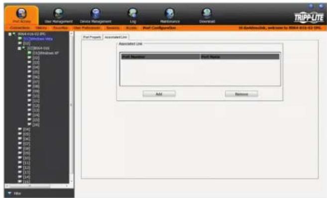
text_image
Start Menu User Management Device Management Log Maintenance Download TRIPPUTE Connections Name Favorites User Features Services Actions Port Configuration RT Server348, welcome to RSPR 012-02 TPL RSPR 012-02 IPC Windows UTX RSPR 012-02 IPC Windows NT RSPR 012-02 IPC RSPR 012-02 IPC RSPR 012-02 IPC RSPR 012-02 IPC RSPR 012-02 IPC RSPR 012-02 IPC RSPR 012-02 IPC RSPR 012-02 IPC RSPR 012-02 IPC RSPS RSPS RSPS RSPS RSPS RSPS RSPS RSPS RSPS RSPS RSPS RSPS RSPS RSPS RSPS RSPS RSPS RSPS RSPS RSPS RSPS RSPS RSPS RSPS RSPS RSPSS RSPSS RSPSS RSPSS RSPSS RSPSS RSPSS RSPSS RSPSS RSPSS RSPSS RSPSS RSPSS RSPSS RSPSS RSPSS RSPSS RSPSS RSPSS RSPSS RSPSS RSPSS RSPSS RSPSS RSPSS RSPS RSPS RSPS RSPS RSPS RSPS RSPS RSPS RSPS RSPS RSPS RSPS RSPS RSPS RSPS RSPS RSPS RSPS RSPS RSPS RSPS RSPS RSPS RSPS RSPs RSPs RSPs RSPs RSPs RSPs RSPs RSPs RSPs RSPs RSPs RSPs RSPs RSPs RSPs RSPs RSPs RSPs RSPs RSPs RSPs RSPs RSPs RSPs RSPs RSPss RSPss User Management - Device Management - Log - Maintenance - Download - Access... Remove... Add... Remove...OSD Operation (continued)
Multi-View Configuration
The Multi-View page is used to set up viewing of extended monitors for remote KVM sessions. Up to four displays from one computer can be connected to the KVM switch and viewed separately in a remote session.
Note: Multi-View function is not available on B064-008-01-IPG and B064-016-01-IPG models.
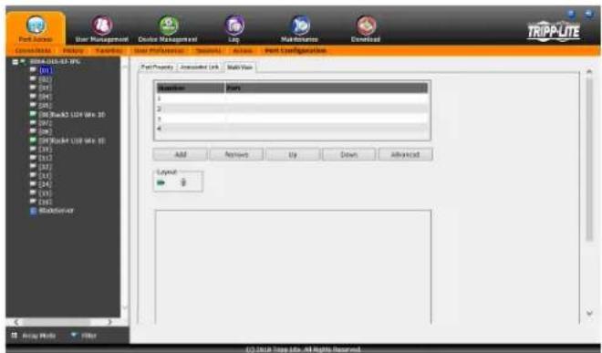
text_image
Project Manager Star Management Device Management City Multi-Application Download TRIPP-LITE Create/Develop User Resources Accounting User Resources Description Access Edit Configuration Project Property : Advanced Link Multi-View Add Remove Up Down Advanced Layout 9 File Edit Stop Info, All Rights Reserved.Setting Up Extended Displays
- Connect up to four Server Interface Units (SIU) (ex. Tripp Lite's B055-001-SER) to the video ports on a computer, then connect each SIU to a port on the KVM switch via Cat5e cable
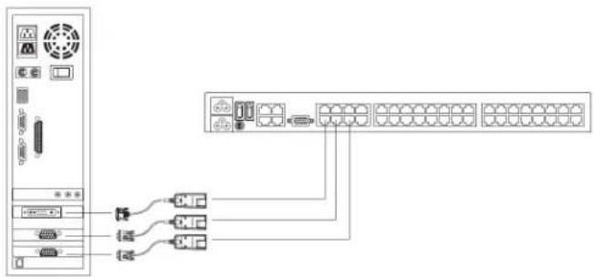
flowchart
graph TD
    A["服务器"] --> B["交换机"]
    A --> C["路由器"]
    A --> D["网络1"]
    A --> E["网络2"]
    A --> F["网络3"]
    A --> G["网络4"]
    A --> H["网络5"]
    A --> I["网络6"]
    A --> J["网络7"]
    A --> K["网络8"]
    A --> L["网络9"]
    A --> M["网络10"]
    A --> N["网络11"]
    A --> O["网络12"]
    A --> P["网络13"]
    A --> Q["网络14"]
    A --> R["网络15"]
    A --> S["网络16"]
    A --> T["网络17"]
    A --> U["网络18"]
    A --> V["网络19"]
    A --> W["网络20"]
- Configure the KVM ports connected to the extended displays by first clicking Add.
- The Setup Multi-View Setting window will pop up with a list of the KVM ports, as shown below.
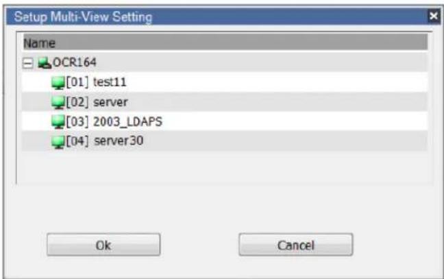
text_image
Setup Multi-View Setting Name OCR164 [01] test11 [02] server [03] 2003_LDAPS [04] server30 Ok Cancel- Select a KVM port connected to the computer with the extended displays, then click OK. Repeat for all extended displays.
- As KVM ports are added, they will appear in the Port List and Preview Window:
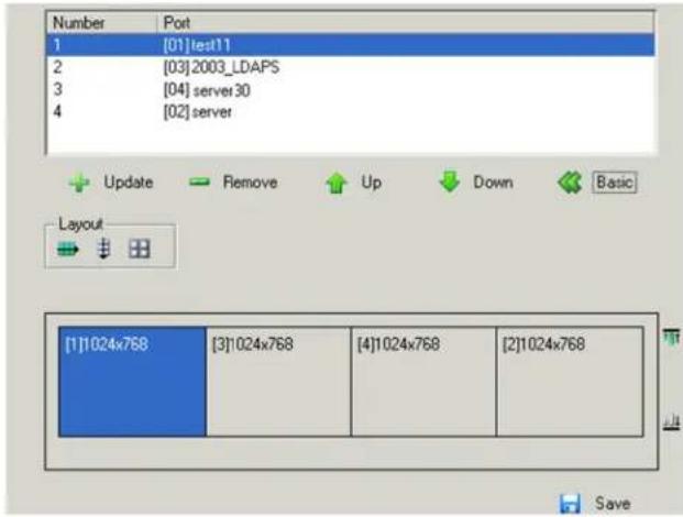
text_image
Number Port 1 [01]test11 2 [03]2003_LDAPS 3 [04]server30 4 [02]server Update Remove Up Down Basic Layout [1]1024x768 [3]1024x768 [4]1024x768 [2]1024x768 Save- Set the preferred layout and click Save.
| Option Usage | |
| Port List | Shows the KVM ports added for extended view. Up to four KVM ports can be added and all must be connected to the same computer.Number:Lists the order in which each KVM port will be shown in the Preview Window, from left to right.Port:Lists the KVM port name added to the extended display setup. |
| Add | Click this icon to open the Setup Extended Display Setting dialog box to select the KVM ports connected to a computer. |
| Remove Click | Click to delete a KVM port from the Port List. |
| Up / Down | Click to move a KVM port up or down in the Port List.This will also change the KVM port's screen position in the Preview Window. |
| Advanced Click | Click to show additional layout options. |
| Basic Click | to show fewer layout options. |
| Layout | Provides three layout options: Horizontal, Vertical and Boxed. This determines how the Display Panel Window appears in a remote session, as shown in the Preview Window. |
| Preview Window | The preview window provides a sample of how the Display Panel Window and screens within it will look during a remote session. Each screen displays the monitor's resolution.Note: The Display Panel Window appears in a remote session when you click the Multiple Displays icon. |
| These icons appear around the preview window when Advanced is selected. Click an icon to align the screens at the top, bottom, left or right of the window. The options appear at the top or right side of the preview window, depending on which Layout is selected. | |
| Save Click to save changes made to the configuration. | |
OSD Operation (continued)
Blade Configuration
Blade Servers that are connected to the switches display below the KVM switches in the Sidebar. This section describes accessing and configuring the blade servers, and associating the blades with KVM switch ports. By associating a blade server or blade with a port, the servers and blades are integrated into the Sidebar tree view and appear as devices connected to the port.
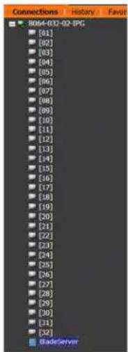
text_image
B064-032-02-SPG [01] [02] [03] [04] [05] [06] [07] [08] [09] [10] [11] [12] [13] [14] [15] [16] [17] [18] [19] [20] [21] [22] [23] [24] [25] [26] [27] [28] [29] [30] [31] [32] BadeServerThe Blade Configuration page is where the associations between blade servers and ports on the KVM switch get created. To access this page, select the blade server or blade, then click the Blade Configuration sub-section tab.
For IBM and Dell blade servers, the entire chassis gets associated with a port, and each blade in the chassis will appear in the tree as a child port of the associated port—as shown by the screenshot of port 08 below.
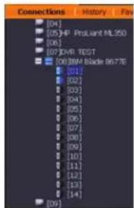
text_image
[04] [05]HP ProJoint ML350 [06] [07]OHR TEST [08]IBM Blade 8677E [03] [02] [03] [04] [05] [06] [07] [08] [09] [10] [11] [12] [13] [14] [09]For HP blade servers, associations are made on a blade by blade basis. Each blade is associated with a single port. To access a blade, click on its port entry in the tree.
Associating Ports
Device View
Port association begins by clicking the Blade Configuration subsection tab in the menu bar. The page comes up in Device View, listing all of the KVM switch's ports, and the blade servers (IBM and Dell servers), or individual blades (HP servers) that have been associated with them.
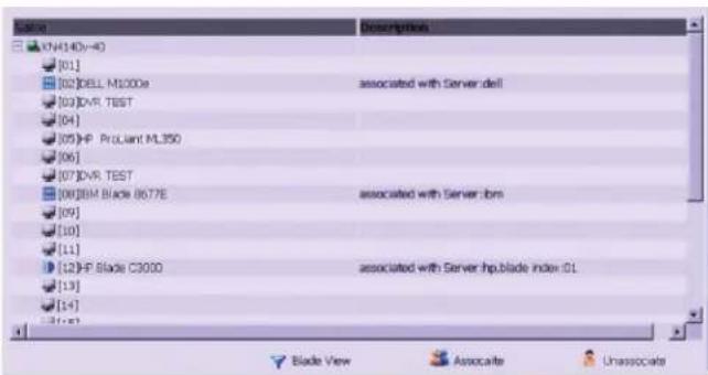
text_image
Name [01] [02]DELL M1000e [03]DVR. TEST [04] [05]HP ProLiant ML350 [06] [07]DVR. TEST [08]BIM Black 8677E [09] [10] [11] [12]HP Blade C3000 [13] [14] [15] Descriptions associated with Server.dll associated with Server.btm associated with Server.hp.blade index iGL Blade View Associate UnassociateTo associate a blade server or blade with a port, follow the steps below.
- Select the port in the main panel.
- Click Associate.
- In the screen that comes up, select the blade server or individual blade that you want to associate with the selected port.
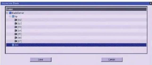
text_image
Associate Blade Name BladeServer hp [01] [02] [03] [04] [05] [06] [07] bm Save Cancel- Click Save.
After the association completes successfully, the blade icon appears next to the associated port in the Sidebar tree. To access the device running on the blade, click on its entry in the Sidebar tree.
OSD Operation (continued)
Blade Configuration (continued)
Blade View
At the bottom of the main panel is a button labeled Blade View, which toggles between Device view and Blade view. Click on it to bring up the Blade View.
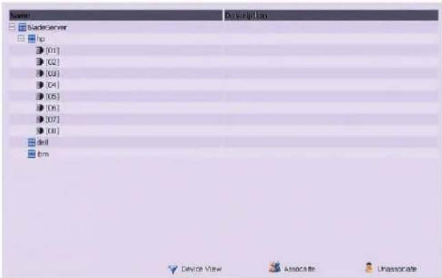
text_image
Name: Bladeserver ho [01] [02] [03] [04] [05] [06] [07] [08] Shell bm Device View Associate UnassociateBlade View lists all of the blade servers (IBM and Dell servers) and individual blades (HP servers) that are installed on the system, and the ports (if any) that they are associated with. To make an association from the blade view, you first select a blade server or blade, then select a KVM port to associate it with as follows.
- Select the blade server or blade in the main panel.
- Click Associate.
- In the screen that appears, select the port that you want to associate it with.
- Click Save.
After the association completes successfully, the blade icon appears next to the associated port in the Sidebar tree. To access the device running on the blade, click on its entry in the Sidebar tree.
Disassociating Ports
To break the association between a port and a blade or blade server, simply select the association in the main panel, and then click Unassociate.
User Management
The User Management section allows Super Administrators, and Administrators and Users who have been given User Management permission, to add/edit accounts on the KVM switch. If an account has not been given User Management permission, the User Management icon will not show up in the OSD when they log in. The User Management section is displayed differently when accessing the OSD via web browser or one of the non-browser clients. The web browser version contains two sub-sections, one for Accounts and one for Groups. The non-browser version contains one section, in which both User accounts and Group accounts are displayed in the list on the left side of the screen. The non-browser version also includes filtering options below the User/Group list. Note: Administrators with User Management permission can only add/edit Administrator and User accounts. Users with User Management permission can only add/edit User accounts. Super Administrators can add/edit all account types.
Adding User Accounts
There is a default Super Administrator account on the KVM switch that can be used to set up the KVM switch. The default Super Administrator username is administrator, and the default password is password. It is strongly recommended that you update this default accounts username and password to something unique. To add a new user account, do the following:
- Highlight Users from the list on the left side of the page, and then click the Add button at the bottom of the screen. The user information page opens.
- Enter in the appropriate information for the account you are creating, and click the Save button when you are done. The contents of the user information screen and their meanings are described in the table below.
- Upon clicking Save, a prompt appears to inform you that the operation succeeded. Click the OK button to exit.
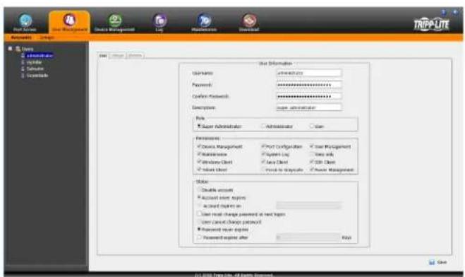
text_image
User Information User Name: 2018-03 Password: ********** Confirm Network: ********** Description: super administrator Role Super Administrator Administrator Sign Permissions Course Manager: Print Configuration User Management Maintenance Paper List Tools with Windows Client Data Client Tools List Select Client Print to Optimize Power Management Status: Double account Account Event Engine Account Engine on User must change password at text login User Account Change password Password Error Engine Password Error after Help © 2018 Top Line, All Rights Reserved.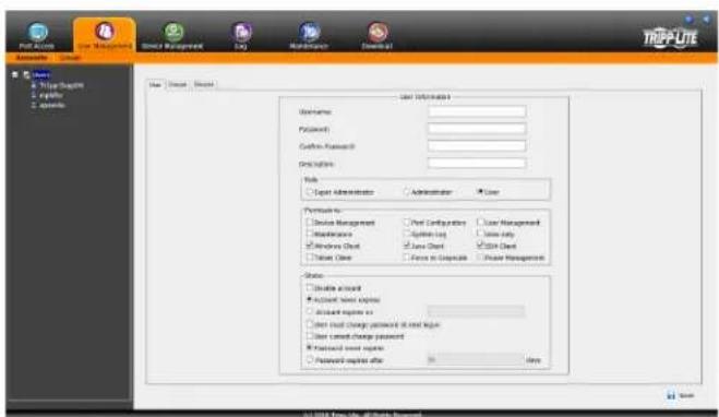
text_image
User Information Username: Password: Cashin Password: Description: Help Export Administrator Administrator Use Permissions to: Device Management Print Configurations User Management Maintenance System Log Use only Windows Check Use Check Store Check Force to Corporate Private Management Status: Create account Account new access Account register to: Start local change password at next page User current change password Password register after OK © 2014 New York, Atlanta, WashingtonOSD Operation (continued)
User Management (continued)
Adding User Accounts (continued)
| Field Description | |
| Username | Enter a username for the account here. The username can contain up to 16 characters, and must meet the Account Policy requirements set in the Security sub-section. (See Security section under Device Management for details.) |
| Password | Enter a password for the account here. The password can contain up to 16 characters, and must meet the Account Policy requirements set in the Security sub-section. (See Security section under Device Management for details.) |
| Confirm Password | For security purposes you must re-enter the password. If the password does not match the password you just entered in the previous field, you will not be allowed to save the account information. |
| Description Enter any additional information that you want to describe the account. This is an optional field. | |
| Role | Select the type of account that you will be creating; Super Administrator, Administrator or User. There is no limitation on the number of each type of account that can be created, only a limit on the number of total accounts. You can create up to 64 accounts on the KVM switch.Super Administrator – This account type has full access to all aspects of the KVM switch. They can fully access all computers/devices connected to the KVM, change any and all settings, and add/edit any account type.Administrator – This account type defaults at full access to the KVM switch, the same as a Super Administrator; however, which ports the account has Configuration access to is determined by a Super Administrator or Administrator that creates/edits the account.. Also, Administrators with User Management permission are limited to adding/editing Administrator and User accounts.User – This account type defaults at no access to the KVM switch, and is only given the initial permissions of Windows Client, Java Client and SSH Client. Super Administrators and Administrators can customize a User profile however they like. If a User is given User Management permission, they are only allowed to add/edit other User accounts. |
| PermissionsNote: Power Management is not a selectable field and has no functionality, regardless of whether or not the box is checked. | The permission settings in this section of the user information page determine what functionality the account is able to use. Check the checkbox next to the permission to enable it for the account. Leave it unchecked to deny the account access to that functionality.Device Management – Gives an account to access to the KVM settings found in the Device Management section, such as network and advanced network management (ANMS) settings. (See Device Management section under OSD Operation for details.) If this checkbox is not checked, the Device Management icon will not appear when the account logs into the OSD.Port Configuration – Allows an account to edit the Port Configuration settings for individual KVM ports. (See Port Configuration section for details.) Note: The Port Configuration setting simply allows for an account to be given Configuration access to the connected ports. Configuration permission for each port must still be given via the Access sub-section of the Port Access section, or via the Devices tab in the Adding/Editing Users section.User Management – Allows an account to add/edit other accounts. Administrators can add/edit Administrator and User accounts. Users can add/edit other User accounts. Super Administrators can add/edit all account types. If this checkbox is not checked, the User Management icon will not appear when the account logs into the OSD.Maintenance – Gives the account access to the settings and functionality found in the Maintenance section, which includes upgrading the KVM and SIU firmware, and backing up and restoring the KVM settings, in addition to other features. (See Maintenance section for details.) If this checkbox is not checked, the Maintenance icon will not appear when the account logs into the OSD.System Log – Gives the account access to the Log section of the OSD, where they can view events that have taken place on the installation and customize notification settings. (See Log section for details.) If this checkbox is not checked, the Log icon will not appear when the account logs into the OSD.View Only – Limits the account to viewing the video of connected computers only. They will not be able to perform keyboard and mouse functions.Windows Client – Gives the account access to the browser and non-browser versions of the Windows client.Java Client – Gives the account access to the browser and non-browser versions of the Java client.SSH Client – Allows the account access to the KVM switch via a SSH client.Telnet Client – Allows the account to access the KVM switch via a Telnet Client.Force to Grayscale – Forces the account to view remote video in black and white. |
| Status This section determines how long an account or password has until it expires or needs to be changed.Disable Account – Disables an account, preventing it from accessing the KVM switch. This gives you an alternative to deleting the account, in which you can disable the account, and then reinstate it in the future without having to re-enter the account settings.Account Never Expires – If this option is checked, the account will stay active forever, or until deactivated manually.Account Expires On – To set a date for the account to be disabled on, check this checkbox and enter in a date in the corresponding field.User Must Change Password at Next Logon – To force the account to change their password the next time they logon, check this checkbox. The next time the account logs on, they will be prompted to enter in a new password.User Cannot Change Password – Check this checkbox to prevent the user from changing their password on their own.Password Never Expires – If this option is checked, the account’s password will stay active forever, or until manually forced to be changed.Password Expires After – To force an account to change their password after a certain number of days, check this checkbox and enter in the number of days until the password expires. | |
OSD Operation (continued)
User Management (continued)
At this point you can do any of the following:
- Assign the new user to a group by selecting the Groups tab in the user's notebook. (See Assigning Users to a Group from the User's Notebook section under User Management for details.)
- Assign port access rights for a user by selecting the Devices tab. (See Device Assignment section under User Management in OSD Operation for details.)
- Add more users and/or create groups and finish configuring the user account later.
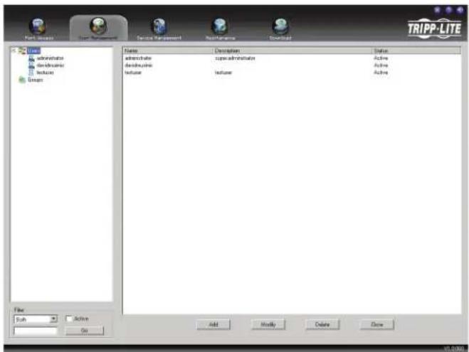
text_image
TRIPP-LITE File Edit View Insert Tools Help Control Settings Maintenance Download Name Description Status administrative core administrators Active designal student student active testuser student active Add Modify Delete Draw Active Add OKModifying User Accounts
To modify a user account, do the following:
- Select the desired user's name from the User List or the Main Panel and click Modify.
- The same as when creating an account, make any necessary changes to the user account and click Save.
Deleting User Accounts
To delete a user account, do the following:
- Select the desired user's name from the Main Panel and click Delete.
- A confirmation dialog box will appear asking if you are sure you want to delete the selected user account. Click OK.
Groups
Groups give Administrators and Super Administrators a convenient way to efficiently manage users and devices. Since device access rights apply to anyone who is a member of the group, administrators need only set them once for the group, instead of having to set them for each user individually. Multiple groups can be defined to allow some users access to specific devices, while restricting other users from accessing them.
Groups – Creating Groups
To create a group, do the following:
- Highlight Groups in the Groups List on the left side of the screen. Note: When accessing the OSD via web browser, you will need to click the Groups sub-section tab first.
- Click Add at the bottom of the main panel. The Group notebook opens, with the Group tab selected:
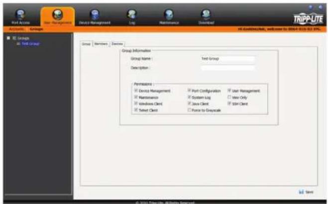
text_image
Rest Accr Group Device Management Log Maintenance Download TRIPP-LITE All bootstruts, welcome to 8064-810-82.0%. Group Information Group Name : Text Group Description : Permissions : Device Management Port Configuration User Management Maintenance System Log View Only Windows Client Java Client Spin Client Text Client Force to Grayscale © 2015 TripLite All Rights ReservedOSD Operation (continued)
User Management (continued)
- The group information screen that appears is similar to the user information screen, except that the Status section is not displayed. Edit the group information the same as with a user account.
- When your selections have been made click Save.
- When the Operation Succeeded popup appears, click OK.
- Click Group in the List panel to return to the main screen. The new group appears in the list and in the main panel, as well.
At this point you can do any of the following:
- Assign users to the group by selecting the Members tab in the group's notebook. (See Assigning Users to a Group from the Group's Notebook section under User Management for details.)
- Assign port access rights for a group by selecting the Devices tab. (See Device Assignment section for details.)
- Add more groups and/or users and finish configuring the group account later.
Groups – Modifying Groups
To modify a group, do the following:
- Click the group's name in the Group list or select the group's name in the Main Panel and click Modify.
- Make any necessary changes to the group account and click Save.
Groups – Deleting Groups
To delete a group do the following:
- Select the group's name in the main panel and click Delete.
- A confirmation dialog box will appear asking if you are sure you want to delete the selected group account. Click OK.
Assigning Users to Groups
There are two ways to assign users to a group and remove them from a group; via the User's notebook or Group's notebook.
Assigning Users to a Group via the User's Notebook
To assign a user to a group from the User's notebook, do the following:
- Select the user's name from the User List or select the user's name from the Main Panel and click Modify.
Note: Super Administrators can not be assigned to a group, as they already have access to the entire installation.
- When the user's notebook appears, select the Groups tab. A screen similar to the one below appears:
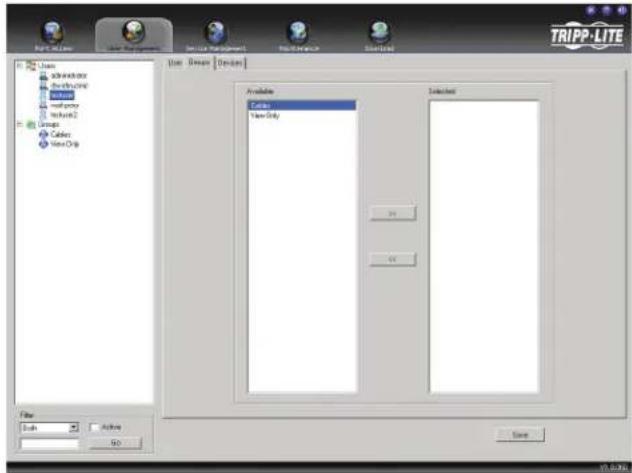
text_image
TRIPP-LITE User Accessories Defaulting Modifiers Network2 Images Cablec Video Chip Data Green Design Available Colors Video Only Selected OK OK Save Help Finish- In the Available column, select the group that you want the user to be in.
- Click the Right Arrow to put the group's name into the Selected column and click Save.
Removing Users From a Group via the User's Notebook
To remove a user from a group from the User's notebook, do the following:
- Select the user's name from the User List or select the user's name from the Main Panel and click Modify.
- When the user's notebook appears, select the Groups tab. A screen similar to the one below appears:
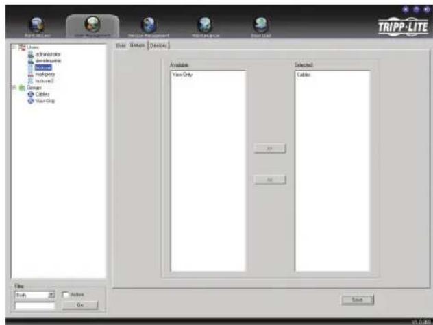
text_image
TRIPP-LITE User adminware Software helpbox helpbox Group Groups Cables View Chip Available: View Only Selected: Cables OK OK Save Finish Finish Go V1.0000- In the Selected column, select the group that you want to remove the user from.
- Click the Left Arrow to remove the group's name from the Selected column and put it back into the Available column. Click Save.
OSD Operation (continued)
User Management (continued)
Assigning Users to a Group via the Group's Notebook
To assign a user to a group from the Group notebook, do the following:
- Select the group's name in the Group list or select the group's name in the Main Panel and click Modify.
- When the group's notebook appears, select the Members tab. A screen similar to the one below appears:
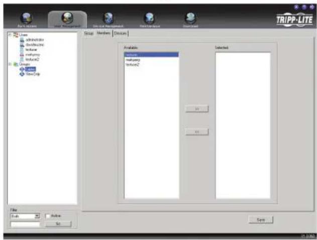
text_image
TRIPP-LITE Group Members Design Available: Invent Involvency Involvency2 Selected: OK Cancel File Auto... Help OK Cancel- In the Available column, select the user that you want to add to the group.
Note: Super Administrators will not show up in the Available list, as they already have access to the entire installation and cannot be added to a group. - Click the Right Arrow to put the user's name into the Selected column.
- Repeat the above for any other users that you want to add to the group.
6.ClickSave when you are done.
Removing Users From a Group via the Group's Notebook
To remove a user from a group via the Group's notebook, do the following:
- Select the group's name in the Group list or select the group's name in the Main Panel and click Modify.
- When the group's notebook appears, select the Members tab. A screen similar to the one below appears:
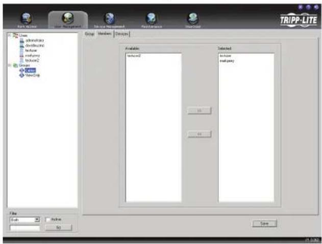
text_image
TRIPP-LITE File Options User Management Show or Settings Report/Source Show/Source Origin Windows Options View/Stop Setup Members Devices Available Institute0 Selected Institute0 Institute0 File Path Save Help Go Get Up Help- In the Selected column, select the user that you want to remove from the group.
- Click the Left Arrow to remove the user's name from the Selected column and send it back to the Available column.
- Repeat the above for any other users that you want to remove from the group.
6.ClickSave when finished.
OSD Operation (continued)
User Management (continued)
Device Assignment
When a user logs onto the KVM switch, the ports that they are allowed to access are displayed in the port list. Ports that they are not allowed to access are not displayed. Port access rights, as well as access to virtual media functionality and configuration settings, is assigned on a port-by-port basis in the user or group Device tab. To access the Device tab, you must pull up the user or group information page, and then click on the Device tab at the top-right of the page.
The Device tab page includes a list of the master KVM switch and its ports on the left, and three permission columns to the right of the list.
- Access – Determines if the account can access the port, and if so, whether they have View Only or Full access.
- USB – Determines if the account can access virtual media mounted to the port, and if so, whether they have Read or Read/Write access.
- Config – If the box is checked next to a port, the account is given access to edit the Port Configuration settings. (See Port Configuration section under OSD Operation for details.) Note: For Configuration access to take effect, the account must also have been given Port Configuration permission. (See the Adding User Accounts section under User Management for details.)
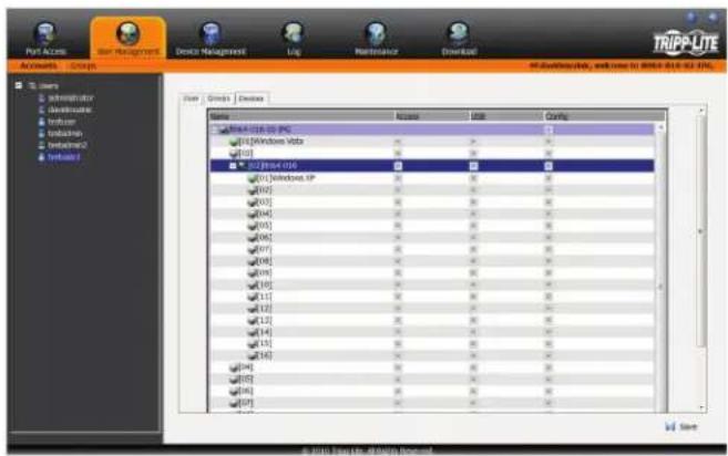
text_image
Port Access Port Management Device Management Up Maintenance Download TRIPP-LITE File Edit/Show, and time to March 2016.03.01. Access USB Config MMA-0108-0108 PC Windows Hube B3 B3 B3 B3 B3 B3 B3 B3 B3 B3 B3 B3 B3 B3 B3 B3 B3 B3 B3 B3 B3 B3 B3 B3 B3 B3 B3 B3 B3 B3 B3 B3 B3 B3To assign device permissions, do the following:
-
Select the user/group name from the user/group list, or select the user/group name in the main panel and click the Modify button.
-
In the user/group notebook page that appears, click on the Device tab.
-
Click on the Access, USB or Config checkbox next to the desired port to toggle through the permission options. For the Access and USB columns, you can choose between full access, view only access or no access. For the Config column, you can choose between enabled or disabled. The permission types are exactly the same as those described in the Access sub-section. (See Access section for details.)
-
When you have finished assigning permissions, click the Save button.
Note: You can simultaneously assign port access to multiple ports using the [Shift] or [Ctrl] keys. To highlight a group of consecutive ports, start by highlighting the first port, hold down the [Shift] key, and then highlight the last port that you wish to highlight. All ports from the first one you highlighted to the last will be highlighted. You can then click on any of the permission checkboxes to change that permission for all of the highlighted ports. To highlight multiple non-consecutive ports, start by highlighting the first port, hold down the [Ctrl] key, and then highlight each additional port one by one while continuing to hold down the [Ctrl] key. When all of the desired ports are highlighted, click on any checkbox to change that permission for all of the highlighted ports.
OSD Operation (continued)
Device Management
The Device Management section allows Super Administrators, and Administrators/Users who have been given permission, to configure and control the KVM switch. When the Device Management icon is selected, it opens with the Device Information page displayed.
Note: If you do not have permission to configure the KVM switch, the Device Management icon will not appear when you log onto the KVM.
Device Information
The Device Information page displays general information about the settings of the KVM switch, and allows you to configure settings related to the KVM's dual power supplies and temperature sensors.
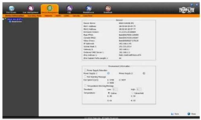
text_image
TRIP-LITE Device Information Loading Price Volume A100 C200 Capacity Database General Device Name: MCC1448-09-25 MCC2 Address: MCC3 Address: MCC4 Address: Main PCN: Command: MCC1448-09-25 Video Driver: IP Address: Subway Mask 5: Subway B: Preferred SIM Server 1: PNC Address 1: PNC Subway Parts Length 1: Win Environment Information Power Supply Controller Power Supply 1 Power Supply 2 Power Supply Manager Power Speed (J/s): 1.50Hz 2.50Hz Temperature Holding Manager Standard: Low: High: Temperature: ● Color ○ Normal ● 10% X: 0% Y: 0% S: 0% S: 0% S: 0% S: 0% S: 0% S: 0% S: 0% S: 0% S: 0% S: 0% S: 0% S: 0% S: 0% S: 0% S: 0% S: 0% S: 0% S: 0% S: 0% S: 0% Tire... Close In the Complete Data ProtocolThe following table describes the contents of the Device Information page.
Note: B064-008-01-IPG and B064-016-01-IPG KVMs Only – Power Supply Detection, Power Supply 1 and Power Supply 2 are the only Environment Information fields that are displayed.
| Item Description | |
| Device Name The port name assigned to the KVM switch is displayed here. | |
| MAC1 Address | The B064- Series KVM switch contains two network interfaces. The MAC address of the first network interface is displayed here. The KVM MAC addresses are also displayed on the bottom panel of the KVM switch. |
| MAC2 Address | The B064- Series KVM switch contains two network interfaces. The MAC address of the second network interface is displayed here. The KVM MAC addresses are also displayed on the bottom panel of the KVM switch. |
| Firmware Version The firmware version of the KVM switch is displayed here. | |
| Main FPGA The Main Field-Programmable-Gate-Array (FPGA) is displayed here. | |
| Console FPGA | The Console Field-Programmable-Gate-Array (FPGA) is displayed here. Note: Does not apply to the B064-008-01-IPG & B064-016-01-IPG KVMs. |
| Video Driver The Video Driver version is displayed here. | |
| IP Address1 The IPv4 IP address of the first network interface is displayed here. | |
| Subnet Mask 1 The IPv4 Subnet Mask of the first network interface is displayed here. | |
| Gateway 1 The IPv4 Gateway of the first network interface is displayed here. | |
| Preferred DNS Server 1 The IPv4 Preferred DNS Server of the first network interface is displayed here. | |
| Alternate DNS Server 1 | The IPv4 Alternate DNS Server of the second network interface is displayed here. Note: Applicable to the B064-008-01-IPG and B064-016-01-IPG KVMs only. |
| IPv6 Address 1 The IPv6 IP address of the first network interface is displayed here. | |
| IPv6 Subnet Prefix Length 1 | The IPv6 Subnet Prefix Length of the first network interface is displayed here. |
| Power Supply Detection | The B064- IPG KVM features dual power supplies. Checking this checkbox will cause the KVM to beep when receiving power from one source, and a message will appear on the local console screen asking you to confirm that you are aware of the situation. |
| Power Supply 1 | The icon to the right of this is gray when power supply 1 is not receiving power. It is blue when power supply 1 is receiving power. |
| Power Supply 2 | The icon to the right of this is gray when power supply 2 is not receiving power. It is blue when power supply 2 is receiving power. |
OSD Operation (continued)
Device Information (continued)
| Item Description | |
| Fan Warning Message | The B064- IPG KVM features temperature sensors that turn the unit's fans on/off at certain temperatures. Checking this checkbox will cause the KVM to beep when the fans stop, and a message will appear on the local console screen asking you to confirm that you are aware of the situation. Note: This notification is prompted whenever a fan stops, and does not necessarily mean that a fan has failed. As fans are programmed to turn off when the unit drops below a certain temperature, this notification may be prompted due to normal operation. |
| Fan Speed (RPM) | The current speed of the KVMs 6 fans is displayed here. The speed of the fan is automatically adjusted according to the temperature. (See Specifications section for fan and sensor location)If any of the KVMs four sensors sense temperatures greater than 89^ ( 32^ ), all fans will be set to spin at half speed.When all four of the KVMs sensors senses the temperature has dropped below 86^ ( 30^ ), all of the fans will be turned off.If any of the KVMs four sensors senses temperatures greater than 113^ ( 45^ ), all fans will be set to spin at full speed.When all four of the KVMs sensors senses the temperature has dropped below 104^ ( 40^ ), all of the fans will be brought down to half speed. |
| Temperature Warning Message | When this checkbox is checked, the system will make a recording in the event log every time that the temperature drops below or rises above the low and high temperature thresholds. |
| Threshold | When the Temperature Warning Message checkbox is checked, the system will make a recording in the event log every time that the temperature drops below or rises above the Low and High temperature thresholds entered here. |
| Temperature | Temperature readings from the temperature sensors are displayed here. You can choose to display the temperature readings in either Celsius or Fahrenheit. (See Specifications section for fan and sensor location.) |
Operating Mode
The Operating Mode sub-section allows the working parameters of the KVM to be set. The settings in this sub-section are described in the table below.
| Item Description | |
| Force All to Grayscale | When this checkbox is checked, all of the accounts in the installation will be forced to view the remote video in black and white. This can help improve keyboard and mouse response time on slower networks. |
| Enable Device List | When this checkbox is checked, the KVM switch will appear in the device list of the non-browser Windows and Java client main pages. If this checkbox is not checked, you will still be able to access the KVM via the non-browser clients, but you will have to manually type in the IP address instead of selecting it from the device list. |
| Enable Adapter IDNote: Not applicable with B064-008-01-IPG and B064-016-01-IPG KVMs. | When this checkbox is checked, the KVM stores the SIU port properties settings and port access rights, so that if the SIU is moved to another port, these settings are moved with it.Note: When Enable Adapter ID is checked, Administrator and User accounts will not see ports that have a powered-off computer, or no computer, connected to them, even if they are given access to those ports. |
| Enable First Rider Transfer | When this checkbox is checked, only the first user on a bus can switch ports. (See Bus Info section under Control Panel in Remote Session Operation for details.) |
| Keyboard/Mouse Broadcast | This drop-down menu allows you to broadcast the keyboard and/or mouse commands to all accessible computers at the same time.This functionality is disabled by default.Note: For the broadcast feature to function properly, all of the computers must be running the same OS, all monitors must be set to the same resolution, and the computer screens must have the same layout. |
| Console Keyboard Language | Select from the drop-down list the language of the keyboard that is connected to the KVM console port. This defaults at English US. |
Network
The Network sub-section is where the KVMs network settings are entered.
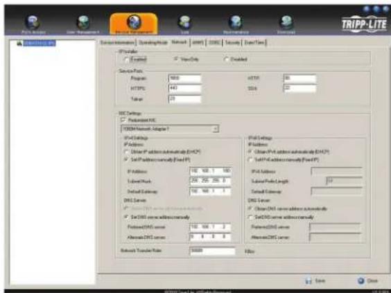
text_image
TRIPP-LITE Network Environment: Desktop/Network Network (DOS) Security DataTime Configuration ✓ Default ✓ View/View ✓ Disabled Service Type: Program: 10000 HTTP: 442 Size: 28 DNS Settings ✓ Default: DNS SVM-Netto-Mware1 - Adapter1 IP-Settings IP Address ✓ User IP address automaticity (EPC) ✓ Self-Address automaticity (Fixed P) IP Address: 100, 100, 1, 100 Label/Work: 256, 256, 256, 0 Default Settings: 100, 100, 1, 1 DNS Server ✓ User DNS server address automaticity Password DNS server: 100, 1, 1, 1, 1, 1, 1, 1, 1, 1, 1, 1, 1, 1, 1, 1, 1, 1, 1, 1, 1, 1, 1, 1, 1, 1, 1, 1, 1, 1, 1, 1, 1, 1, 1 Network Transfer Rate: 50000 PUB Settings IP Address ✓ User IP address automaticity (EPC) ✓ Self-Address automaticity (Fixed P) IP Address: 100, 100, 1, 100 Label/Work: 256, 256, 256, 0 Default Settings: 100, 100, 1, 1, 1, 1, 1, 1, 1, 1, 1, 1, 1, 1, 1, 1, 1, 1, 1, 1, 1, 1, 1, 1, 1, 1, 1, 1, 1, 1, 1, 1, 1, 3OSD Operation (continued)
Network (continued)
The settings in this sub-section are described in the table below.
| Item Description | |
| IP Installer | The B064-Series KVM switch comes with an IP Installer application that allows Windows computers to easily view and edit the KVM's network settings. This section determines what access the IP Installer has to the KVM switch. Enabled – When selected, the IP Installer can locate the KVM switch on the network and display its current IP address. It also allows the IP Installer to be used to change the IP address of the KVM switch.View Only – When selected, the IP Installer can locate the KVM switch on the network and display its current IP address, but it cannot be used to change the IP address of the KVM switch.Disabled – When selected, the IP Installer cannot locate the KVM switch on the network, nor can it be used to change the IP address of the KVM switch. |
| Service Ports | This section allows you to set up port numbers that will be allowed by a firewall. If the port numbers on this page are not allowed access by the firewall, you will not be able to access the KVM switch. Valid entries for all of the service ports are from 1 to 65535. Note: You must enter a different port number for each field. If the KVM is connected to a network without a firewall, it doesn't matter what these ports are set to, as they will have no effect.Program – This is the port number that is used when accessing connected computers via the browser and non-browser Windows and Java clients. It is also the port number that is used when accessing virtual media. The default value is 9000. Note: This port number must match the port number in the non-browser Windows and Java clients when using them to connect to the KVM switch.HTTP – This is the port that is used for a browser login. The default value is 80.HTTPS – This is the port that is used for a secure browser login. The default is 443.SSH – This is the port number that is used when accessing the KVM switch via SSH. The default value is 22.Telnet – This is the port number that is used when accessing the KVM switch via Telnet. The default value is 23. |
| Redundant NIC | The B064-Series KVM switch features two network interfaces. You can assign the same IP address to both, or assign a separate IP address for each. When this checkbox is checked, the same IP address gets assigned to both network interfaces, and the NIC drop-down menu below it is grayed out. If unchecked, the NIC drop-down menu is activated, and you must assign an IP address for each interface. Select a network interface from the drop-down to edit its settings. |
| IPv4 Settings | The B064-Series KVM switch supports both IPv4 and IPv6. If you wish to use an IPv6 IP address, ignore this section.Obtain an IP Address Automatically (DHCP) – When this option is checked, the KVM switch will have its IP address assigned to it by a DHCP server upon booting up, and the remaining fields in this section will be grayed out. This option is checked by default.Set IP Address Manually (Fixed IP) – Check this option if you wish to assign an IP address to the KVM yourself. When checked, the settings fields below will be activated for you to edit.IP Address – Enter in the desired IP address here.Subnet Mask – Enter in the desired Subnet Mask here.Default Gateway – Enter in the desired Default Gateway here.Obtain DNS Server Address Automatically – When this option is checked, the KVM switch will have its DNS Server address assigned to it by a DHCP server upon booting up, and the remaining fields in this section will be grayed out. If you selected to set the IP address manually above, this option will be grayed out, and you will be required to enter the DNS Server address manually as well.Set DNS Server Address Manually – Check this option if you wish to assign a DNS Server address to the KVM yourself. When checked, the settings fields below will be activated for you to edit.Preferred DNS Server – Enter in the preferred DNS Server address here.Alternate DNS Server – Enter in the alternate DNS Server address here. This is an optional field. |
| IPv6 Settings | The B064-Series KVM switch supports both IPv4 and IPv6. If you wish to use an IPv4 IP address, ignore this section.Obtain IPv6 Address Automatically (DHCP) – When this option is checked, the KVM switch will have its IP address assigned to it by a DHCP server upon booting up, and the remaining fields in this section will be grayed out. This option is checked by default.Set IPv6 Address Manually (Fixed IP) – Check this option if you wish to assign an IP address to the KVM yourself. When checked, the settings fields below will be activated for you to edit.IPv6 Address – Enter in the desired IP address here.Subnet Prefix Length – Enter in the desired Subnet Prefix length here.Default Gateway – Enter in the desired Default Gateway here.Obtain DNS Server Address Automatically – When this option is checked, the KVM switch will have its DNS Server address assigned to it by a DHCP server upon booting up, and the remaining fields in this section will be grayed out. If you selected to set the IP address manually above, this option will be grayed out, and you will be required to enter the DNS Server address manually as well.Set DNS Server Address Manually - Check this option if you wish to assign a DNS Server address to the KVM yourself. When checked, the settings fields below will be activated for you to edit.Preferred DNS Server – Enter in the preferred DNS Server address here.Alternate DNS Server – Enter in the alternate DNS Server address here. This is an optional field. |
| Network Transfer Rate | This setting allows you to set the size of the data transfer stream to match your network, by setting the rate at which the KVM transfers data to remote computers. The range is from 4 to 99,999 Kbps. The default is 99999. |
Advanced Network Management Settings
The ANMS sub-section is used to set up login authentication and authorization management from external sources. It is split up into two pages; Event Destination and Authentication, which are explained in the sections that follow.
Event Destination
The Event Destination page allows the KVM to be set up to record and send notifications of events that take place on the system. It allows you to enable and set up notification via SMTP, SNMP, Syslog Server and the Log Server.
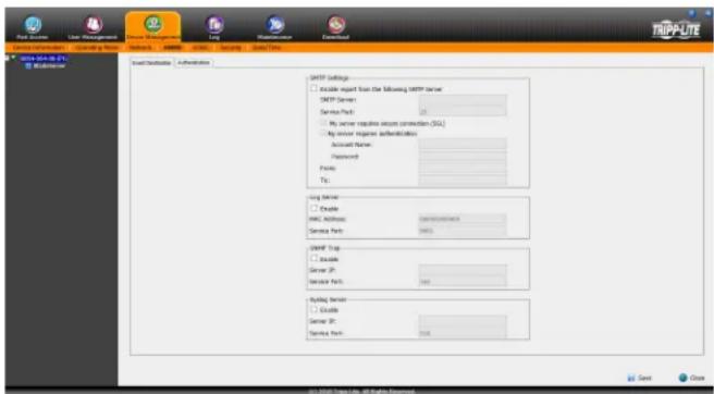
text_image
User Stock to IP User Security | Authentication SMTP Settings □ Enable export from the following HTTP server SMTP Server: Service Port: □ No server defaults except confirmation [SSL] □ Any server logware authentication Account Name: Password: Phone: To: Log Server □ Enable HRC Address: 100% Service Port: HRC SMTP Top □ Enable Server (P): Service Port: 142 Typing Server □ Enable Server (P): Service Port: 158 © 2016-2-19, https://www.trip-site.com/ Send CloseSMTP Settings
The SMTP Settings section allows you to have notifications of system events emailed to you via the SMTP server. To set up this feature, follow the steps below. Note: The Notification Settings, described on page 54, must be enabled for notifications to be sent.
- Check the Enable report from the following SMTP Server checkbox.
- In the SMTP Server field, key in the IPv4 address, IPv6 address or domain name of the SMTP server.
- In the Service Port field, enter in a port that the firewall will allow to be used to access the log server. The valid port range is between 1 and 65535. The default port number is 25.
- If your server requires a secure SSL connection, check the My server requires secure connection (SSL) checkbox.
- If your server requires authentication, check the My server requires authentication checkbox.
- Enter in the Account Name and Password for your SMTP server.
- In the From field, key in the email address that you want the report to show up as being sent from. Note: Only one email address is allowed in the From field, and it cannot exceed 64 Bytes. 1 Byte is equal to 1 English alphanumeric character.
- In the To field, key in the email address(es) you want the report to be sent to. Note: If you are entering more than one address, separate them with a semicolon. The size of all email addresses cannot combine to more than 256 Bytes. 1 Byte is equal to 1 English alphanumeric character.
Log Server
In addition to the log that is built into the OSD, the KVM comes with an external Windows-based log server that can be installed on a computer. (See The Log Server section for details.) The Log Server section on this page is where the external log server can be enabled and set up for use. To do this, follow the steps below.
- Check the Enable checkbox in the Log Server section.
- In the MAC Address field, enter the MAC address of the computer that the log server resides on.
- In the Service Port field, enter in a port that the firewall will allow to be used to access the log server. The valid port range is between 1 and 65535. The default port number is 9001. Note: The port number entered here must not be the same as any of the ports entered into the Network sub-section. (See Network section under Device Management for details.)
SNMP Server
This section allows you to enable SNMP traps to be sent. To enable SNMP traps, do the following (Note: The Notification Settings, described on page 54, must be enabled for notifications to be sent):
- Check the Enable SNMP Agent checkbox.
- In the Server IP field, enter the IPv4 address, IPv6 address or domain name of the computer to be notified of SNMP trap events.
- In the Service Port field, enter in a port that the firewall will allow to be used to access the SNMP server. The valid port range is between 1 and 65535. The default port number is 162. Note: The port number entered here must not be the same as any of the ports entered into the Network sub-section. (See Network section under Device Management in OSD Operation for details.)
Syslog Server
To record all the events that take place on the KVM and write them to a Syslog server, do the following (Note: The Notification Settings, described on page 54, must be enabled for notifications to be sent):
- Check the Enable checkbox in the Syslog Server section.
- In the Server IP field, enter the IPv4 address, IPv6 address or domain name of the Syslog server.
- In the Service Port field, enter in a port that the firewall will allow to be used to access the Syslog server. The valid port range is between 1 and 65535. The default port number is 514. Note: The port number entered here must not be the same as any of the ports entered into the Network sub-section. (See Network section under Device Management in OSD Operation for details.)
OSD Operation (continued)
Advanced Network Management Settings (continued)
Authentication
The Authentication page allows remote authentication to be set up via RADIUS and LDAP/S.
Disable Local Authentication
Check this checkbox to disable local login authentication of the KVM switch. If checked, the switch can only be accessed using LDAP, LDAPS, MS Active Directory, NetDirector (ND) management and/or RADIUS authentication.
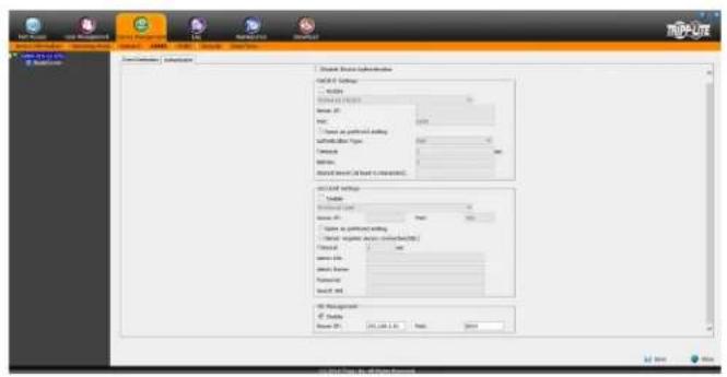
text_image
Database Database Name Database Address Database Name Database Date Database Name Database Name Database Name Database Name Database Name Database Name Database Name Database Name Database Name Database Name Database Name Database Name Database Name Database Name Database Name Database Name Database Name Database Name Database Name Database Name Database Name Database Name Database Name Database Name Database Name Database Name Database Name Database Name Database Name Database Name Database Name Database Name Database Name Database NameRADIUS Settings
To allow authentication and authorization for the B064-Series KVM over IP switch through a RADIUS server, do the following:
- Check the Enable check box in the RADIUS Settings sections.
- Select Preferred or Alternate RADIUS server from the dropdown menu.
-
Fill in the IP address and service port number for either the Preferred or Alternate RADIUS server. You can use the IPv4 address, the IPv6 address or the domain name in the Server IP field.
-
Select the Authentication Type: PAP (Password Authentication Protocol) or CHAP (Challenge-Handshake Authentication Protocol) from the drop-down menu.
-
In the Timeout field, set the time in seconds that the KVM over IP switch waits for a RADIUS server reply before it times out.
-
In the Retries field, set the number of allowed RADIUS retries.
-
In the Shared Secret field, key in the character string that you want to use for authentication between the B064-Series KVM over IP switch and the RADIUS server. A minimum of 6 characters is required.
On the RADIUS server, set the entry for each user as su/xxxx, where xxxx represents the username assigned to the user in the KVM switch. User access rights will be the same as those that were assigned to them in the KVM switch. (See User Management sections for details).
AD / LDAP Authentication and Authorization Settings
To allow authentication and authorization for the B064 Series KVM Switch via AD / LDAP, refer to the information in the table, below:
| Character Meaning | |
| Enable Check the Enable checkbox to allow AD/LDAP authentication and authorization. | |
| Preferred/ Alternative LDAP From the drop-down menu, specify either Preferred LDAP or Alternative LDAP. | |
| Server IP Fill in the IP address of the Preferred or Alternate LDAP server. | |
| Port | Fill in the port number of the Preferred or Alternate LDAP server. For LDAP, the default port number is 389. |
| Timeout Set the time in seconds that the B064-Series KVM Switch waits for an LDAP server reply before timing out. | |
| Admin DN | Consult the LDAP administrator to ascertain the appropriate entry for this field. For example, the entry might look like this: ou=b064-032-04-ip,dc=tripplite,dc=com |
| Admin Name Fill in the LDAP administrator's username. | |
| Password Fill in the LDAP administrator's password. | |
| Search DN Set the distinguished name of the search base. This is the domain name where the search starts for user names. | |
Note: If the LDAP Setting is enabled, the LDAP schema for MS Active Directory must be extended, or an OpenLDAP server must be installed and configured. (See LDAP Server Configuration, in the following section for details.)
NetDirector (ND) Management
To allow authorization for the KVM over IP switch through a NetDirector (ND) server, check Enable and fill in the ND server's IP address and service port in the appropriate fields.
OSD Operation (continued)
Advanced Network Management Settings (continued)
LDAP Configuration — Active Directory
To allow authentication and authorization for the B064-Series KVM Switch via LDAP, the Active Directory's LDAP Schema must be extended so that an extended attribute name for the B064-Series KVM Switch -userprofile - is added as an optional attribute to the person class.
- Authentication refers to determining the authenticity of the person logging in.
- Authorization refers to assigning permission to use the device's various features.
In order to configure the LDAP server, you will have to complete the following procedures: 1) Install the Windows 2003 Support Tools; 2) Install the Active Directory Schema Snap-in; and 3) Extend and Update the Active Directory Schema.
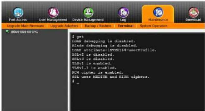
text_image
Part Access User Management Device Management Log Maintenance Download Upgrade Main Firmware Upgrade Adapters Backup / Restore Terminal System Operation B064-094 69 IPS $ get LDAP debugging is disabled. Blade debugging is disabled. LDAP attribute:JKVM8164-userProfile. SSLv2 is disabled. SSLv3 is disabled. TLSv1 is enabled. TLSv1.1 is enabled. BC4 cipher is enabled. SSL uses MEDIUM and HIGH ciphers. $ _Note: To quickly access the LDAP attribute, users can type the word get into the Terminal command line.
Install the Windows 2003 Support Tools
- On your Windows Server CD, open the Support → Tools folder.
- In the right panel of the dialog box that comes up, double click SupTools.msi.
- Follow along with the Installation Wizard to complete the procedure.
Install the Active Directory Schema Snap-in
- Open a Command Prompt.
- Key in regsvr32 schmmgmt.dll to register schmmgmt.dll on your computer.
- Open the Start menu. Click Run and key in mmc /a. Click OK.
- On the File menu of the screen that appears, click Add/Remove Snap-in, then click Add.
- Under Available Standalone Snap-ins, double click Active Directory Schema, click Close and click OK.
- On the screen you are in, open the File menu and click Save.
- For Save in, specify the C:\Windows\system32 directory.
- ForFile name, key in schmmgmt.msc.
- Click Save to complete the procedure.
Creating a Start Menu Shortcut Entry
To create a shortcut entry on the Start Menu for the Active Directory Schema, do the following:
- Right click Start; select: Open all Users → Programs → Administrative Tools.
- On the File menu, select New → Shortcut
- In the dialog box that comes up, browse to or key in the path to schmmgmt.msc (C:\Windows\system32\schmmgmt.msc) and click Next.
- In the dialog box that comes up, key in Active Directory Schema as the name for the shortcut, then click Finish.
OSD Operation (continued)
Advanced Network Management Settings (continued)
Extend and Update the Active Directory Schema
Step 1 - Create a New Attribute:
a) Open Control Panel → Administrative Tools → Active Directory Schema.
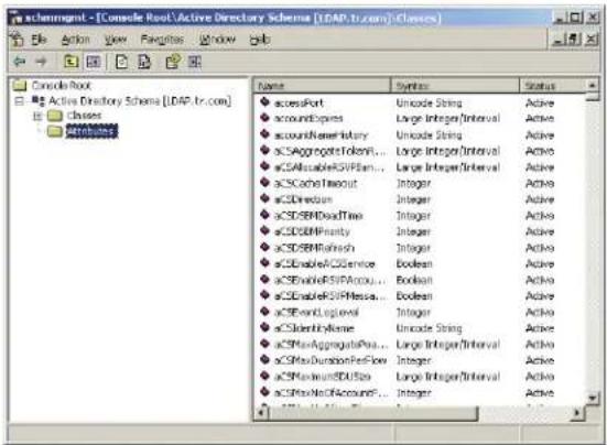
text_image
achemgmt - [Console Root\Active Directory Schema (LDAP.tr.com)\Classes] Name Syntax Status accessPort Unicode String Active accountExpires Large Integer/Interval Active accountRenameIndustry Unicode String Active SCSAggregateTokenR... Large Integer/Interval Active SCSAccessibleSPIPlan... Large Integer/Interval Active SCSCacheTimeout Integer Active SCSDirection Integer Active SCSDBMDataTime Integer Active SCSDBMParity Integer Active SCSDBMRFinish Integer Active SCSDisableACSService Boolean Active SCSEnableRSIFAcqou... Boolean Active SCSDisableRSIFPassa... Boolean Active SCSExtendLogLevel Integer Active SCSIdentifyName Unicode String Active SCSPsAggregatePos... Large Integer/Interval Active SCSPsDurationPerFlow Integer Active SCSPsUnreadDSInfo... Large Integer/Interval Active SCSPsNoICAccountF... Integer Activeb) In the left panel of the screen that comes up, right-click Attributes:
c) Select New Attribute.
d) In the warning message that appears, click Continue to bring up the Create New Attribute dialog box.
e) Fill in the dialog box according to the example below and click OK to complete step 1 of the procedure.
- Common Name – usrprofile
- LDAP Display Name – userprofile
- Syntax – Unicode String
- Minimum - 1
• Maximum - 255
Note: The Unique X500 Object ID uses periods, not commas.
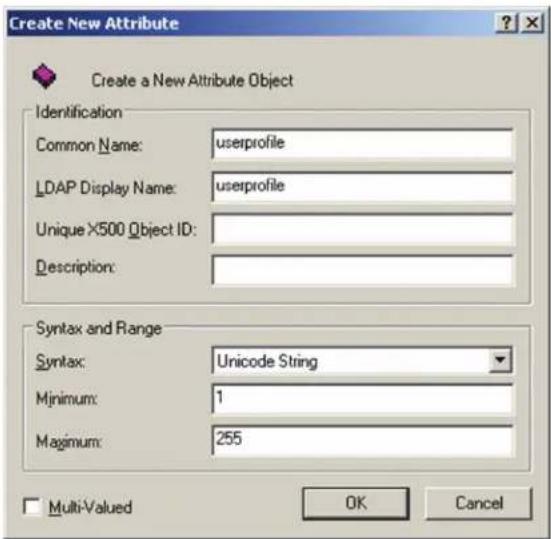
text_image
Create New Attribute Create a New Attribute Object Identification Common Name: userprofile LDAP Display Name: userprofile Unique X500 Object ID: Description: Syntax and Range Syntax: Unicode String Minimum: 1 Maximum: 255 Multi-Valued OK CancelStep 2 - Extend the Object Class With the New Attribute:
a) Open Control Panel → Administrative Tools → Active Directory Schema.
b) In the left panel of the screen that comes up, select Classes.
c) In the right panel, right-click person:
text_image
schrmgmt - [Console Root\Active Directory Schema [LDAP.tr.com] Classes] File Action View Favorites Window Help Console Root Active Directory Schema [LDAP.tr.com] Classes Attributes None Type Status De organizationalPerson Type 88 Active Or organizationalRole Structural Active Or organizationUnit Structural Active Or packageRegistration Structural Active Pack person]^Type 88 Active Pack physicalLocation Structural Active PK pK:\CertificateTemplate Structural Active PK pKIEnrollmentService Structural Active PK postsAccount Auxiliary Active Ab postsGroup Auxiliary Active Ab printQueue Structural Active Pri meanDelay Structural Active Ord) Select Properties; the person Properties page comes up with the General tab displayed. Click the Attributes tab.
text_image
person Properties General | Relationship | Attributes | Default Security | person Description: Person Common Name: Person ≥500 OID: 2.5.6.6 Class Type: Type 88 Category person Show objects of this class while browsing Class is active OK Cancel Applye) Select the Attributes tab and click the Add button:
text_image
person Properties General | Relationship | Attributes | Default Security | person Mandatory: cn Optional: accessPort attributeCertificateAttribute seeAlso serialNumber on telephoneNumber userPassword Add... Remove OK Cancel ApplyOSD Operation (continued)
Advanced Network Management Settings (continued)
f) In the list that comes up, select userprofile, then click OK to complete step 2 of the procedure.
text_image
Select Schema Object Select a schema object: uPNSuffixes url userAccountControl userCert userCertificate userClass userParameters userPassword userPKCS12 userPrincipalName userProfile userSharedFolder userSharedFolderOther userSMIMECertificate userWorkstations uSNChanged uSNCreated uSNDSALastObjRemoved USNIntersite uSNLastObjRem uSNSourceStep 3 - Edit Active Directory Users With the Extended Schema:
a) Run ADSI Edit. (Installed as part of the Support Tools.)
b) Open Domain, and navigate to the cn=users dc=tripplite dc=com node.
c) Locate the user you wish to edit.
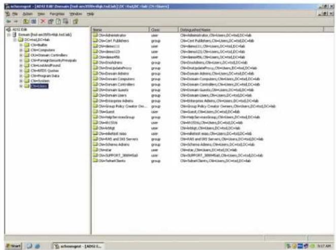
text_image
Schroger - [ADSI EAB] Domain [Add and Add/Build, Lab/Lab] DC: 14xDC-Club (CN-Series) Start Schroger - [ADSI EAB] Domain [Add and Add/Build, Lab/Lab] DC#us,DC-Club AdminOperator Group Group Group Group Group Group Group Group Group Group Group Group Group Group Group Group Group Group Group Group Group Group Group Group Group Group Group Group Group Group Group Group Group Group Group Group Group Group Group Group Group Group Group Group Group Group Group Group Group Group User User User User User User User User User User User User User User User User User User User User User User User User User User User User User User User User User User User User User User User User User User User User User Userd) Right-click on the user's name and select Properties.
e) On the Attribute Editor page of the dialog box that appears, select userprofile from the list.
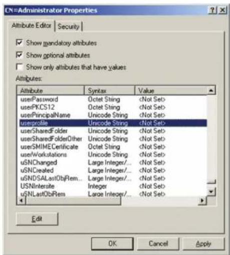
text_image
CN=Administrator Properties Attribute Editor | Security | Show mandatory attributes Show optional attributes Show only attributes that have values Attributes: Attribute Syntax Value userPassword Octet Stringf) Click Edit to bring up the String Attribute Editor:
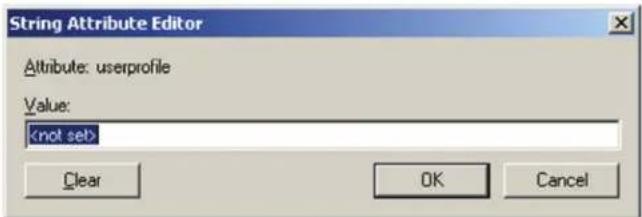
text_image
String Attribute Editor Attribute: userprofile Value:g) Replace the value shown with su/xxxx, where xxxx represents the username assigned to the user in the KVM switch. User access rights will be the same as those that were assigned to them in the KVM switch. (See User Management section for details.)
OSD Operation (continued)
Advanced Network Management Settings (continued)
h) Click OK. When you return to the Attribute Editor page, the userprofile entry now reflects the new permissions:
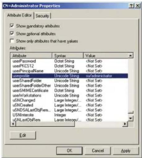
text_image
CN=Administrator Properties Attribute Editor | Security | Show mandatory attributes Show optional attributes Show only attributes that have values Attributes: Attribute Syntax Value userPassword Octet Stringi) Click Apply to save the change and complete the procedure.
j) Repeat Step 3 (Edit Active Directory Users With the Extended Schema) for any other users you wish to add.
OpenLDAP Server
OpenLDAP is an Open source LDAP server designed for UNIX platforms. A Windows version can be downloaded from: http://download.bergmans.us/openldap/openldap-2.2.29/openldap-2.2.29-db-4.3.29-openssl-0.9.8awin32_Setup.exe.
OpenLDAP Server Installation
After downloading the program, launch the installer, select your language, accept the license and choose the target installation directory. The default directory is:
c:\Program Files\OpenLDAP.
When the Select Components dialog box appears, select install BDB-tools and install OpenLDAP-slapd as NT service, as shown in the diagram, below:
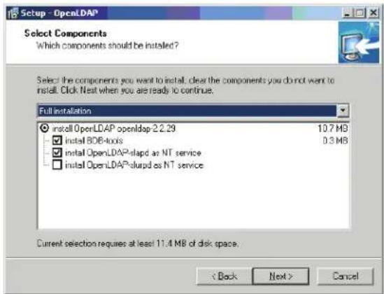
text_image
Setup - OpenLDAP Select Components Which components should be installed? Select the components you want to install: clear the components you do not want to install. Click Next when you are ready to continue. Full installation ● install OpenLDAP openldap 2.2.29 10.7 MB ✓ install BOB-locks 0.3 MB ✓ install OpenLDAP-slapd as NT service □ install OpenLDAP-slapd as NT service Current selection requires at least 11.4 MB of disk space. < Back Next > CancelOSD Operation (continued)
Advanced Network Management Settings (continued)
OpenLDAP Server Configuration
The main OpenLDAP configuration file, slapd.conf, has to be customized before launching the server. The modifications to the configuration file will do the following:
- Specify the Unicode data directory. The default is ./ucdata.
- Choose the required LDAP schemas. The core schema is mandatory y.
- Configure the path for the OpenLDAP pid and args start up files. The first contains the server pid, the second includes command line arguments.
- Choose the database type. The default is bdb (Berkeley DB).
- Specify the server suffix. All entries in the directory will have this suffix, which represents the root of the directory tree. For example, with suffix dc=tripplite,dc=com, the fully qualified name of all entries in the database will end with dc=tripplite,dc=com.
- Define the name of the administrator entry for the server (rootdn), along with its password (rootpw). This is the server's super user. The rootdn name must match the suffix defined above. (Since all entry names must end with the defined suffix, and the rootdn is an entry)
An example configuration file is provided in the figure, below:
ucdata-path /ucdata
include ./schema/core.schema
pidfile /run/slapd.pid
argsfile ./run/slapd.args
database bdb
suffix "dc=tripplite, dc=com"
rootdn "cn=Manager, dc=tripplite, dc=com"
rootpw secret
directory /data
Starting the OpenLDAP Server
To start the OpenLDAP Server, run slapd (the OpenLDAP Server executable file) from the command line. slapd supports a number of command line options, the most important option is the d switch that triggers debug information. For example, a command of slapd -d 256 would start OpenLDAP with a debug level of 256, as shown in the following screenshot:
Note: For details about slapd options and their meanings, refer to the OpenLDAP documentation.
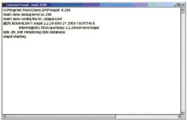
text_image
D:\Program Files\OpenLDAP\slapd -d 256 main: now debug level is: 256 main: now config file is:islapd.com/ @(F) OpenLDAP: slapd 2.2.29 (Oct 21 2005 16:01:14) MMohr@BELTIRA:openldap-2.2.29/servers/slapd bdb_db_init Initializing BDB database slapd startingCustomizing the OpenLDAP Schema
The schema that slapd uses may be extended to support additional syntaxes, matching rules, attribute types, and object classes. In the case of the B064-Series KVM Switch, the B064-Series KVM Switch User class and the permission attribute are extended to define a new schema. The extended schema file used to authenticate and authorize users logging in to the B064-Series KVM Switch is shown in the figure, below:

text_image
Copyright (C) 2008 TrappLit
All Rights Reserved.
Author Judy
Date: November 27, 2008
Summary: Define the LDAP schema
# #TEPPLITCE CID=(1.3.6.1.4.21317)
# attributes (1.3.6.1.4.1.21317.1.1.4.2.2 NAME 'penation' EQUALITY case/gene-March SUBSTR case/gene/Substrings-March SYNTAX 1.3.6.1.4.1.1466.115.121.1.35 SINGLE-VALUE] objectiam (1.3.6.1.4.1.21317.1.1.4.1.2 NAME 'User' SUP organizationalPerson STRUCTURAL MAT Operations User CertificationLDAP DIT Design and LDIF File
LDAP Data Structure
An LDAP Directory stores information in a tree structure known as the Directory Information Tree (DIT). The nodes in the tree are directory entries, and each entry contains information in attribute-value form. An example of the LDAP directory tree for the B064-Series KVM Switch is shown in the figure below:
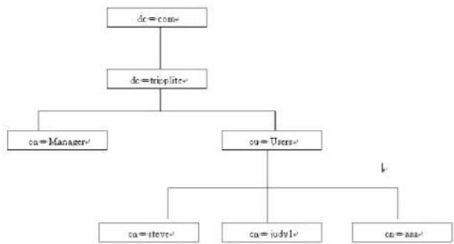
flowchart
graph TD
    A["dc = com"] --> B["dc = trioplite"]
    B --> C["ca = Manager"]
    B --> D["ca = Users"]
    D --> E["ca = steve"]
    D --> F["ca = judy1"]
    D --> G["ca = news"]
OSD Operation (continued)
Advanced Network Management Settings (continued)
DIT Creation
The LDAP Data Interchange Format (LDIF) is used to represent LDAP entries in a simple text format (please refer to RFC 2849). The figure below illustrates an LDIF file that creates the DIT for the B064-Series KVM Switch directory tree (shown in the figure in the previous section).
| 序号 | |
| ## | |
| ## | Copyright (C) 2008 Tripelite |
| ## | All Rights Reserved. |
| ## | Author Judy |
| ## | Date: November 27, 2008 |
| ## | Summary Define the LDA# scheme |
| ## | |
| ## |
| dr: de-triplite, dr=com |
| objectclass: top |
| objectClass: doObject |
| objectClass: organization |
| do: cm=Manager, de=tripplies, de=cam |
| objectclass: top |
| objectclass: person |
| objectclass: organizationall erron |
| en: Manager |
| sn: Manager |
| dn: orgUsers, d:impulse, de:com |
| objectclass top |
| objectclass organizationalUnit |
| ou: Users |
| dn: no steve,ou:Users,de:nipline,dr:con: |
| objectclass: top |
| objectclass: person |
| objectclass: organizationalPerson |
| objectclass: User |
| on: stave |
| on: stave |
| permission: w,v,p,i,cl |
| used?password password |
| ou: Users |
The following figure illustrates an LDIF file that defines the OpenLDAP group for the B064-Series KVM Switch.
| # |
| # |
| # |
| # Copyright (C) 2008 TrappLite |
| # All Rights Reserved. |
| # Author: Judy |
| # Date: November 27, 2008 |
| # Summary: Define the LDAP scheme |
| # |
| # |
| # |
| dx: cm-judy1,on=Users, dc=trappate, dc=com |
| objectclass: top |
| objectclass: person |
| objectclass: organizationalPerson |
| objectclass: User |
| cm-judy1 |
| cm-judy1 |
| usedPassword password |
| dx: ex=cc, de=tapiplate, dc=com |
| objectClass: groupOBNames |
| cn: ccc |
| member: ex=judy1, co=users, de=tapiplate, dc=com |
| da: en=bbb, de=tipplate, de=com. |
| objectClass: groupOfNames |
| cn: bbb |
| member: en=ccc, de=tipplate, de=com. |
| da: cn=aaa, de=kipplate, de=com |
| objectClass: groupOfNames |
| cn: aaa |
| member: cn=bbb, de=kipplate, de=com |
Using the New Schema
To use the new schema, do the following:
- Save the new schema file (e.g., B064-Series KVM switch.schema) in the /OpenLDAP/ schema/ directory.
- Add the new schema to the slapd.conf file, as shown in the figure:
- Restart the LDAP server.
- Write the LDIF file and create the database entries in init.ldif with the ldapadd command, as shown in the following example:
ldapadd -f init.ldif -x -D "cn=Manager,dc=tripplite,dc=com" -w secret
| urdata-path | /udata |
| include | /schema/core elevateda |
| include | /schema/cosine schema |
| include | /schema/unetorgperson schema |
| include | /schema/openldap schema |
| include | /schema/ schema |
| # Define global ACLs to disable default read access |
| access to din. children="our-Users, dc-tripplite, dc-com" |
| by: dn-"cr-Manager, dc-tripplite, dc-com"write |
| by self read |
| by anonymous auth |
| by * none |
| pidfile | /run/slapd.pid |
| argfile | /run/slapd args |
| # BDB database definitions |
| database | bdb |
| suffix | "de=tripplate, de=com" |
| rootdn | "cn=Manager, de=tripplate, de=com" |
| rootpw | secret |
| directory | /data |
SNMP Agent
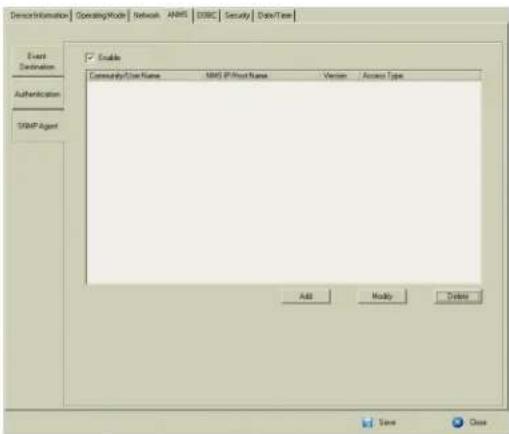
text_image
Event Destination Authentication SMTP Agent Enable Community/Case Name SMTP IP Host Name Version Access Type Add Modify Delete Save DoseTo set SNMP Agent, do the following:
- Check Enable.
- Click Add. A window appears.
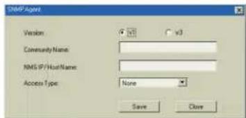
text_image
DBP Agent Version: v15 v3 Community Name: NMS IP/HostName: Access Type: None Save Close- Select the Version.
- Key in the Community Name.
- Key in NMS IP/Host Name.
- Select the Access Type and click Save.
OSD Operation (continued)
OOBC
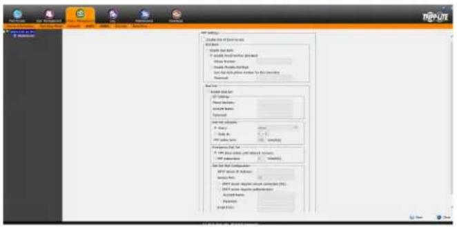
text_image
Add Text Add Text to Text • Add Text to Text • Add Text to Text • Add Text to Text • Add Text to Text • Add Text to Text • Add Text to Text • Add Text to Text • Add Text to Text • Add Text to Text • Add Text to Text • Add Text to Text • Add Text to Text • Add Text to Text • Add Text to Text • Add Text to Text • Add Text to Text • Add Text to Text Add Text to Text Add Text to Text Add Text to Text Add Text to Text Add Text to Text Add Text to Text Add Text to Text Add Text to Text Add Text to Text Add Text to Text Add Text to Text Add Text to Text Add Text to Text Add Text to Text Add Text to Text Add Text to Text Add Text to Text Add Text to Text Add Text to Text Add Text to Text Add Text to Text Add Text to Text Add Text to Text Add Text to Text Add Text to TextIn case the B064-Series KVM switch cannot be accessed via the LAN, it can be accessed via the switch's modem port. To enable support for PPP (modem) operation, check the Enable Out of Band Access checkbox. When checked, Enable Dial Back and Enable Dial Out functions become available.
Enable Dial Back
If the Enable Dial Back checkbox is checked, the switch will disconnect calls that dial into it, and dial back to one of the entries specified in the table below.
| Setting Description | |
| Enable Fixed Number Dial Back | When the Enable Fixed Number Dial Back checkbox is checked, the KVM will hang up on the modem when there is an incoming call, and dial back to the modem represented by the phone number mentioned in the Phone Number field. |
| Enable Flexible Dial Back | When the Enable Flexible Dial Back checkbox is checked, the KVM can dial back to any modem specified by the user connecting to the KVM. Simply enter a password into the Password field, and when a user connects to the KVM, they will be prompted to enter a username and password. They should enter the phone number of the modem that they want to dial back to as the username, and use the password that is set in the Password field as the password. |
Enable Dial Out
To use the dial out feature, you must establish an account with an Internet Service Provider (ISP), and use a modem to dial out to your ISP account. Check the Enable Dial Out checkbox to enable this feature. The settings found in this section are described in the table below.
| Setting Description | |
| ISP Settings | Enter in the Phone Number, Account Name and Password that you use to connect to your ISP here. |
| Dial Out Schedule | This section allows you to determine what times your KVM switch will dial out over your ISP connection.Every – Check this option to choose between the 5 options in the drop-down menu; Never, every Hour, every 2 Hours, every 3 Hours or every 4 Hours.Daily at – Check this option to enter in a time that the KVM will dial out over your ISP every day. Use the hh:mm format to specify the desired time.PPP Online Time – Enter in the amount of time you want a ISP connection to last before it is terminated. A setting of 0 means that the ISP connection will not automatically disconnect itself. |
| Emergency Dial Out | In the event that the KVM gets disconnected from the network, or the network goes down, this feature will automatically connect via the ISP dial up connection.PPP Stays Online Until Network Recovery – When this option is checked, the ISP connection will remain active until the network connection is reestablished.PPP Online Time – When this option is checked, the ISP connection will remain active for the amount of time you set here. A setting of 0 means that the ISP connection will not automatically disconnect itself. |
| Dial Out Mail Configuration | This section allows you to set up email notifications of systems events via SMTP server. These notifications will be sent over the ISP network connection, in contrast to the notifications set up in ANMS Event Destination (see SMTP Settings), which go out over the standard network.SMTP Server IP Address – Enter the IPv4 address, IPv6 address or domain name of you SMTP server here.SMTP Server Requires Secure Connection (SSL) – Check this checkbox if your server requires a secure SSL connection.SMTP Server Requires Authentication – Check this checkbox if your server requires authentication. When checked, the Account Name and Password fields are activated. Enter in the Account Name and Password for your SMTP server.In the From field, key in the email address that you want the report to show up as being sent from.Note: Only one email address is allowed in the From field, and it cannot exceed 64 Bytes. 1 Byte is equal to 1 English alphanumeric character.In the To field, key in the email address(es) you want the report to be sent to.Note: If you are entering more than one address, separate them with a semicolon. The size of all email addresses cannot combine to more than 256 Bytes. 1 Byte is equal to 1 English alphanumeric character. |
When you are done making all of your changes, click the Save button.
The following section describes the settings found in the Security sub-section.
OSD Operation (continued)
OOBC (continued)
Follow the steps below to setup and access the B064-Series KVM Switch via dial-in modem:
-
Set up your hardware configuration to match the diagram below. You will need to use Cat5e cable and the included RJ45 to DB9 Adapter to connect the B064-Series KVM Switch's modem port to the modem.
-
From your computer, use your modem terminal program to dial into the B064-Series KVM Switch's modem.
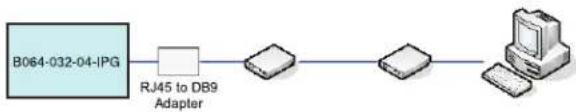
Note: If you don't know the B064-Series KVM Switch modem's serial parameters, get them from the system administrator. An example of setting up a modem terminal program under Windows XP is provided on the next page.
- Once the connection is established, open your browser, and specify 192.168.192.1 in the URL box.
Note: The default username and password are blank.
From here, operation is the same as if you had logged in from a browser or with the AP programs.
Connection Setup Example (Windows XP)
To set up a dial-in connection to the B064-Series KVM Switch under Windows XP, do the following:
-
From the Start menu, select Control Panel—Network Connections—Create a New Connection.
-
When the Welcome to the New Connection Wizard dialog box appears, click Next to move on.
-
In the Network Connection Type dialog box, select Connect to the network at my workplace and click Next.
-
In the Network Connection dialog box, select Dial-up connection and click Next.
-
In the Connection Name dialog box, key in a name for the connection and click Next.
-
In the Connection Availability dialog box, you can select either Anyone's use or My use only, depending on your preferences, then click Next.
Note: If you are the only user on this computer, this dialog box won't appear.
-
In the Phone Number to dial dialog box, key in the phone number of the modem connected to the B064 Series KVM Switch (be sure to include country and area codes, if necessary), then click Next.
-
In the Completing the New Connection Wizard dialog box, check Add a shortcut to this connection on my desktop and click Finish.
This completes the connection setup. Double click the desktop shortcut icon to make a dial-in connection to the B064-Series KVM Switch.
Security
Login Failures
The Login Failures section allows you to set up the parameters for what occurs when an account fails to login successfully. To enable the
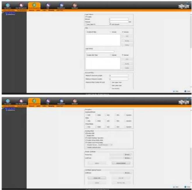
text_image
TRIM-LITE User Settings If User Name: User Name: User Address: User Address: User Address: User Address: User Address: User Address: User Address: User Address: User Address: User Address: User Address: User Address: User Address: User Address: User Address: User Address: User Address: User Address: User Address: User Address: User Address: User Address: User Address: User Address: User Address: UserAddress User Address User Address User Address User Address User Address User Address User Address User Address User Address User Address User Address User Address User Address User Address User Address User Address User Address User Address User Address User Address User Address User Address User Address User Address User Address User Address User Address User Address User Address User Address User Address User Address User Address User AddressOSD Operation (continued)
Security (continued)
settings entered here, check the Enable checkbox. The table below describes the settings found in this section.
Note: When the Login Failures settings are disabled, there is no restriction on the number of login failures. It is strongly recommended that you enable these features, and that both the Lock Client PC and Lock Account settings are enabled.
| Setting Description | |
| Allowed | Determines the number of failed login attempts an account gets before they are prevented from accessing the KVM switch. |
| Timeout | Determines the amount of time that the user is prevented from accessing the KVM switch after exceeding the maximum number of failed login attempts. |
| Lock Client PC | When this checkbox is checked, the computer used to unsuccessfully access the KVM will be locked out after exceeding the maximum number of failed login attempts. Note: This feature blocks the computer using its IP address. If the computer IP address is changed, it will be able to access the KVM in spite of this setting. |
| Lock Account | When this checkbox is checked, the account used to unsuccessfully access the KVM will be locked out after exceeding the maximum number of failed login attempts. |
Filtering
To enable IP and/or MAC filtering, click the IP Filter Enable and/or MAC Filter Enable checkbox. There are a maximum of 100 filters allowed for each.
- If the include button is checked, all the addresses within the filter range are allowed access to the B064-Series KVM Switch; all other addresses are denied access.
- If the exclude button is checked, all the addresses within the filter range are denied access to the B064-Series KVM Switch; all other addresses are allowed access.
IP Filtering
To add an IP filter:
- Check the IP Filter Enable check box.
- Click Add. A dialog box similar to the one below appears:
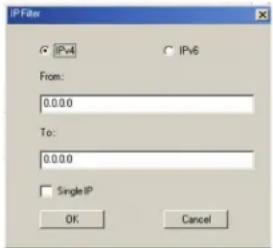
text_image
IPFilter G IPv4 IPv6 From: 0.0.0.0 To: 0.0.0.0 Single IP OK Cancel- Check the IPv4 or IPv6 option, depending on what type of address you are filtering. Note: You must access the OSD via the local console or one of the non-browser clients in order to filter an IPv6 address. When accessing the OSD via browser, you are only able to set up IPv4 filters.
- To filter a single IP address, check the Single IP checkbox and enter the IP address you want to filter in the From field. Note: This feature is not available when accessing the OSD via browser. To filter a single IP address via the browser OSD, you must enter in the same IP address in both the From and To fields.
- To filter a range of IP addresses, enter the starting IP address in the From field, and the ending IP address in the To field.
- After filtering in the addresses, click OK.
- Repeat these steps for any additional IP addresses you want to filter.
To delete an IP filter:
Select the desired IP filter from the list and click Remove.
To modify an IP filter:
- Select the desired IP filter from the list and click Edit. An Edit dialog box similar to the Add dialog box will appear.
- Delete the old start IP address and replace it with the new one.
- Delete the old end IP address and replace it with the new one. Click OK.
Note: To block a computer from accessing the B064-Series KVM Switch, you do not need to filter both its IP address and its MAC address. Any computer blocked by an IP filter will be denied access to the KVM switch, even if the computer is allowed to access the KVM switch under the MAC filters that are set up.
OSD Operation (continued)
Security (continued)
Login String
The Login String allows the KVMs IP address to be more secure by adding extra text to the end of it. When text is entered into the Login String field, users will need to include a forward slash (/) and the Login String at the end of the URL to access the KVM switch. For example, if a Login String of abcdefg is entered, the user must enter a URL such as 192.168.0.126/abcdefg.
The following characters are allowed in the login string: 0 through 9, a through z, A through Z, \~ ! @\$^&*()_+'◇,,l
The following characters are not allowed: %":/?#[Space]
Note: If a Login String is not entered, anyone can access the KVM switch using the IP Adress alone, making the installation less secure.
MAC Filtering
To add a MAC filter:
- Click Add. A dialog box similar to the one below appears:
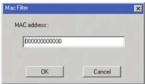
text_image
Mac Filter MAC address : 00000000000 OK Cancel-
Type in the desired MAC address and click OK.
-
Repeat these steps for any additional MAC addresses you want to filter.
To delete a MAC filter:
Select the desired MAC filter from the list and click Remove.
To modify a MAC filter:
- Select the desired MAC filter from the list and click Edit. An Edit dialog box box appears.
- Delete the old address and replace it with the new one. Click OK.
Note: To block a computer from accessing the B064-Series KVM Switch, you do not need to filter both its IP address and its MAC address. Any computer blocked by a MAC filter will be denied access to the KVM switch, even if the computer is allowed to access the KVM switch under the IP filters that are set up.
If any filters have been configured, they appear in the IP Filter and/or MAC Filter list boxes.
Account Policy
The Account Policy section allows rules for usernames and passwords to be regulated. The settings in this section are described in the table below.
| Item Description | |
| Minimum Username Length | Sets the minimum number of characters required for each username. Values from 1 to 16 can be entered. |
| Minimum Password Length Sets | the minimum number of characters required for each password. Values can be from 0 to 16. |
| Password Must Contain at Least | One Upper Case – Checking this box will require that each password contain one upper case letterOne Lower Case – Checking this box will require that each password contain one lower case letterOne Number – Checking this box will require that each password contain one numberNote: Current usernames and passwords are not affected when these settings are changed. Only usernames and passwords that are created after these settings have been changed must follow the rules. |
| Disable Duplicate Login | Checking this box will prevent users from logging in with the same username and password to open more than one session at the same time. |
| Enforce Password History | Checking this box will require users to create a unique password that does not match the last (x) number of passwords used prior. |
Encryption
This section allows you to set different encryption settings for the Keyboard/Mouse, Video and Virtual Media functions of the KVM switch. You can choose any combination of encryption methods (DES, 3DES, AES and/or RC4), you can choose to randomly switch between them or you can choose no encryption at all. Although enabling encryption will add more security to you installation, it can also slow down system performance (mouse, keyboard, video), with the following having the most impact:
- RC4 impacts performance the least out of the four encryption methods. DES is second to least in impact, followed by 3DES and AES.
- Of all the possible combinations, a combination of RC4 and DES impacts performance the least.
OSD Operation (continued)
Security (continued)
Working Mode
The Working Mode section allows you to enable/disable operation features of the KVM switch. The table below describes the available settings.
| Setting Description | |
| Enable ICMP When this box is checked, the KVM switch can be pinged. If it is not checked, the KVM cannot be pinged. | |
| Enable FIPS Enables the FIPS security standard. | |
| Enable Multiuser Operation | When this box is checked, multiple accounts (up to 32) can log onto the same bus (see Bus Info section under Control Panel in Remote Session Operation for details) at the same time. If not selected, the KVM switch can only be simultaneously accessed by the number of users that the unit has buses for. The B064-016-02-IPG and B064-032-02-IPG have 3 buses each (1 local, 2 remote), and the B064-016-04-IPG and B064-032-04-IPG have 5 buses each (1 local, 4 remote). |
| Enable Virtual Media Write Operation | When this box is checked, applicable virtual media (see Virtual Media section under Control Panel in Remote Session Operation for details) will be able to have information written to it from the remote computer. If this box is not checked, any virtual media mounted to a remote computer will only be able to be viewed, and not written to. |
| Enable Local Virtual Media | When this box is checked, applicable USB media (see Virtual Media section under Control Panel in Remote Session Operation for details) can be connected to the USB ports on the front of the KVM switch and accessed on the connected computers. If this box is not checked, USB media connected to the KVM will not be accessible on the connected computers. |
| Browser Service | When this box is checked, browser access to the KVM switch can be limited by selecting one of the three options in the drop-down menu.Disable Browser – Browser access is disabled completely.Disable HTTP – Browser access is permitted, but only when using a HTTPS URL.Disable HTTPS – Browser access is permitted, but only when using a HTTP URL. |
| Disable Authentication | When this box is checked, no authentication procedures are used to check accounts logging into the KVM. All users will be logged onto the KVM switch with full access, regardless of what account type they are.Note: Enabling this setting creates a very unsecure situation, and is not recommended. |
Private Certificate
When logging into the KVM switch over a secure (SSL) connection, a certificate is required to ensure you are logging into a secure site. If a certificate is not recognized as secure, you will be prompted each time you log in to verify you want to continue to the website. This section allows you to import an Encryption Key and Certificate. To import an Encryption Key and Certificate, follow the steps below.
- Click the Browse button to the right of Private Key, browse to where your private encryption key file is located, and then select it.
- Click the Browse button to the right of Certificate, browse to where your certificate file is located, and then select it.
- Click the Upload button to complete the procedure. Note: Both the Private Key and Certificate must be imported at the same time. Clicking the Restore Default button returns the KVM to the default certificate that came installed on it.
OSD Operation (continued)
Security (continued)
Certificate Signing Request
The Certificate Signing Request section provides an automated way of obtaining and installing a CA signed SSL server certificate. To perform this operation, follow the steps below.
- Click the Create CSR button. The following dialog box appears.
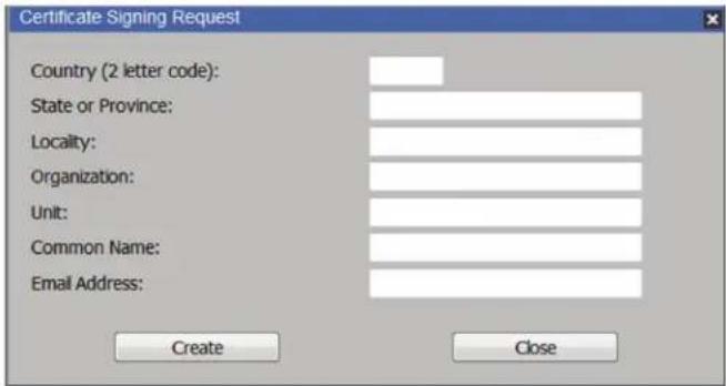
text_image
Certificate Signing Request Country (2 letter code): State or Province: Locality: Organization: Unit: Common Name: Email Address: Create Close- Fill in the form with the appropriate information for your company. The table below is an example of a filled out form.
| Field Example | |
| Country (2 letter code) TW | |
| State or Province Taiwan | |
| Locality Taipei | |
| Organization Your Company, Ltd. | |
| Unit Techdoc Department | |
| Common Name | www.mycompany.com Note: This entry must be the exact domain name of the site that you want the certificate to be valid for. If the site's domain name is www.mycompany.com, and you enter mycompany.com, the certificate will not be valid. |
| Email Address administrator@yourcompany.com | |
- When all fields have been filled out (all fields are required), click the Create button.
- Click the Get CSR button, and then save the certificate file to a convenient location on your computer. This is the file that you give to the third party CA to apply for their signed SSL certificate.
- After you have received the certificate from the third party CA, save it to a convenient location on your computer. In the Certificate Signing Request section of the Security page, click the Browse button and navigate to and select the certificate.
- Click the Upload button. Note: When uploading the file, the KVM checks to make sure the specified information still matches. If it does, the file is accepted. If it does not match, the file will be rejected. If you want to remove the certificate (e.g. to replace it with a new one because of a domain name change), click the Remove CSR button.
OSD Operation (continued)
Date/Time
The Date/Time page allows the user to set the date and time parameters for the KVM switch. The following section describes the settings on this page.
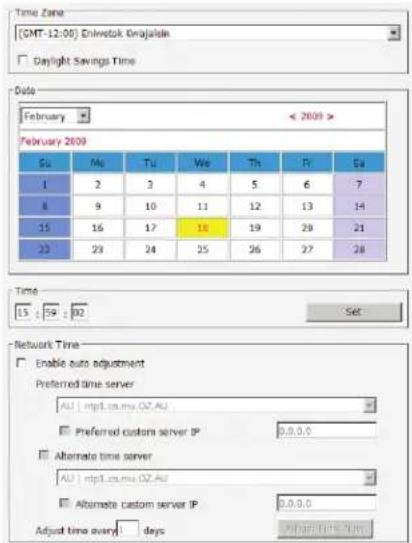
text_image
Time Zone (CMT-12:00) Eniwetak Onajalan Daylight Savings Time Data February 2009 February 2009 Su Mu Tu We Th Ft Sa 1 2 3 4 5 6 7 8 9 10 11 12 13 14 15 16 17 18 19 20 21 20 23 24 25 26 27 28 Time 15 : 54 : 00 Set Network Time Enable auto adjustment Preferred time server AU | mtp1.cs.mw.OZ.AU Preferred custom server IP 0.0.0.0 Alternate time server AU | mtp1.cs.mw.OZ.AU Alternate custom server IP 0.0.0.0 Adjust time every days After time every dayBlade Server Configuration
For Super Administrators and Administrators/Users who have been given permission, when you access the Device Management section with a Blade Server selected in the Sidebar tree, its Configuration page appears.
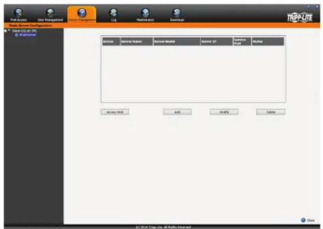
text_image
Path Access User Management Service Management Link Maintenance Delete TRAPLITE Data Source: C#Function 304.02.00 195 B- Recognition Access Back Add Modify Delete © 2014 Top site - All Rights ReservedTime Zone
- Select the Time Zone and City that most closely resembles where the KVM switch is in using the drop-down menu at the top of this section. - If your area uses Daylight Savings Time, check the Daylight Savings Time checkbox.
To manually set the date and time, do the following:
- In the Date section, select the current month using the drop-down menu.
- If needed, click the < or > buttons in the Date section to move backward or forward to the correct year.
- In the calendar in the Date section, click on the current day.
- In the Time section, enter in the current time using the 24 hour HH:MM:SS format.
- Click the Set button in the Time section to apply your changes.
Network Time
To have the time automatically synchronized to a network time server, do the following:
- Check the Enable Auto Adjustment checkbox.
- Select a time server from the Preferred Time Server drop-down list; or, check the Preferred Custom Server IP checkbox and enter in the IP of your preferred time server.
- If desired, repeat step two to enter an Alternate Time Server.
- Key in the desired number of days between synchronization in the Adjust Time Every _Days field.
- Click the Adjust Time Now button to synchronize immediately.
Adding a Blade Server
To configure a new blade server, do the following.
- Select its icon in the Sidebar tree, then click Add in the main panel. The Setup Blade Server dialog box appears, with the Step 1 tab displayed.
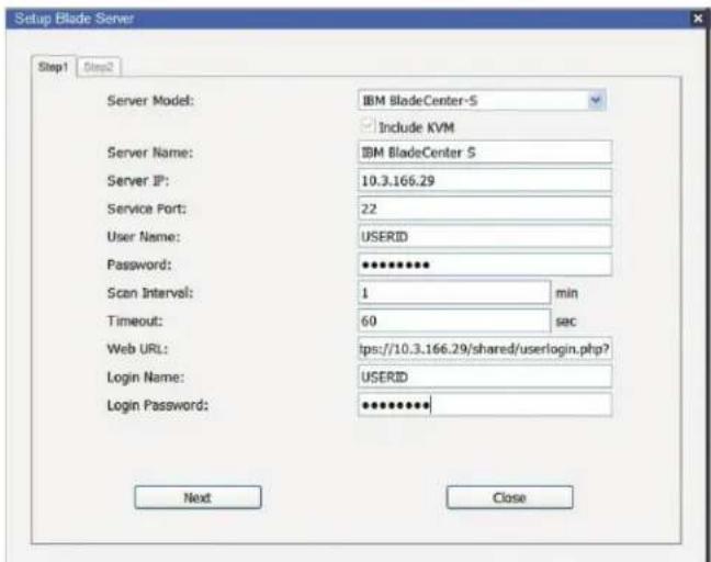
text_image
Setup Blade Server Step1 Step2 Server Model: IBM BladeCenter-S Include KVM Server Name: IBM BladeCenter S Server IP: 10.3.166.29 Service Port: 22 User Name: USERID Password: ********** Scan Interval: 1 min Timeout: 60 sec Web URL: tps://10.3.166.29/shared/userlogin.php? Login Name: USERID Login Password: ********** Next CloseOSD Operation (continued)
Blade Server Configuration (continued)
- Fill in the fields according to the information provided in the following table.
| Field Description | |
| Server Model Select your blade server model from this drop down list. | |
| Include KVM | This item is for information purposes and can't be edited. If the server supports a KVM function, this box is checked. Otherwise, it is unchecked. |
| Server Name Enter in a name for the blade server here. | |
| Server IP Enter in the IP address (IPv4, IPv6, or domain name) used to access the blade server via a serial connection (Telnet or SSH). | |
| Service Port Enter the port number used for serial access. | |
| User Name Enter in the username required for serial access authentication. | |
| Password Enter in the password required for serial access authentication. | |
| Scan Interval | Enter in the interval that determines how frequently the KVM switch scans the blade server for information. |
| Timeout | Enter in the amount of time that the KVM switch will wait for a response from the blade server before it stops scanning. |
| Web URL Enter in the IP address (IPv4, IPv6, or domain name) used to access the blade server via web browser. | |
| Login Name Enter in the username required for browser authentication. | |
| Login Password Enter in the password required for browser authentication. | |
- When you have finished configuring the fields, click Next to bring up the dialog box with the Step 2 tab displayed.
- The Step 2 dialog presents a summary of the blade server's configuration, including the number of blades installed. Click Save to add the blade server to the installation.
Modifying / Deleting a Blade Server
- To modify a blade server's configuration, first select it in the Sidebar tree, and then click Modify. Make your changes on the Setup Blade Server dialog box.
- To remove a blade server, first select it in the Sidebar tree, and then click Delete.
Web Access
To access the blade server's Web page, first select it in the Sidebar tree, and then click Access Web.
OSD Operation (continued)
Log
The B064-Series KVM switch logs all the events that take place and writes them to a log file. The Log section is split into two sub-sections; Log Information and Notification Settings.
Log Information
The Log Information sub-section is where you can view the contents of the built-in log file. When opened, a page similar to the one below appears.
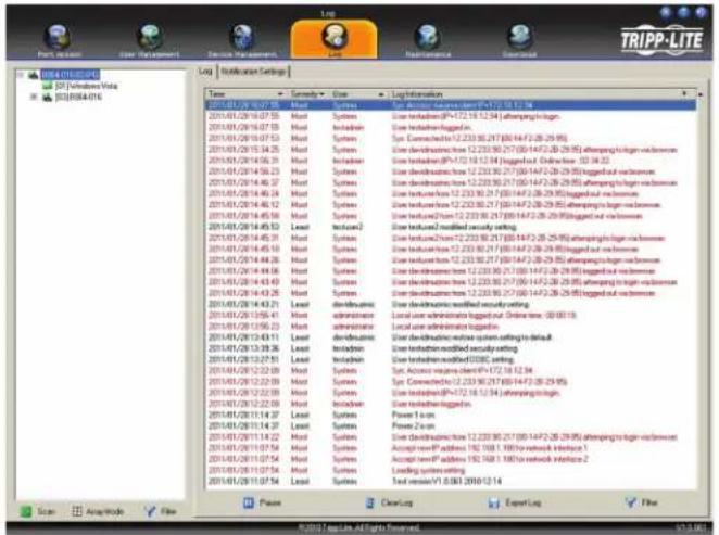
text_image
TRIPP-LITE Log Installation Settings Name Commodity Direct Liquid Information 01/01/03/26 07:05:55 Modl Systems User teduction (IP-172.18.12.94) attempting log-in. 01/01/03/26 07:05:55 Modl Systems User teduction logged-in. 01/01/03/26 07:05:53 Modl Systems Typ Connectors from 12.233.96.217 (80/14/26-28-995) attempting log-in via browsers 01/01/03/26 07:05:53 Modl Systems User teduction from 12.233.96.217 (80/14/26-28-995) attempting log-in via browsers 01/01/03/26 07:05:53 Modl Systems User teduction from 12.233.96.217 (80/14/26-28-995) being logged out via browsers 01/01/03/26 07:05:53 Modl Systems User teduction from 12.233.96.217 (80/14/26-28-995) being logged out via browsers 01/01/03/26 07:05:53 Modl Systems User teduction (IP-172.18.12.94) attempting log-in. 01/01/03/26 07:05:53 Modl Systems User teduction logged-in. 01/01/03/26 07:05:53 Modl Systems Typ Connectors from 12.233.96.217 (80/14/26-28-995) being logged out via browsers 01/01/03/26 07:05:53 Modl Systems User teduction from 12.233.96.217 (80/14/26-28-995) becoming log-in via browsers 01/01/03/26 07:05:53 Modl Systems User teduction from 12.233.96.217 (80/14/26-28-995) being logged out via browsers 01/01/03/26 07:05:53 Modl Systems User feduction from 12.233.96.217 (80/14/26-28-995) being logged out via browsers 01/01/03/26 07:05:53 Modl Systems User teduction from 12.233.96.217 (80/14/26-28-995) ached version set to default 01/01/03/26 07:05:53 Modl Systems User teduction installed security setting 01/01/03/26 07:05:53 Modl Systems Local user tabulated log-in, Online time: 08:08:19. 01/01/03/26 07:05:53 Modl Systems Local user tabulated log-in. 01/01/03/26 07:05:53 Modl Systems User teduction update system setting to default 01/01/03/26 07:05:53 Modl Systems User teduction installed security setting 01/01/03/26 07:05:53 Modl Systems User teduction installed ODBC setting 01/01/03/26 07:05:53 Modl Systems Typ Access request client from 172.18.12.94 01/01/03/26 07:05:53 Modl Systems Typ Connectors from 12.233.96.217 (80/14/26-28-995) 01/01/03/26 07:05:53 Modl Systems User teduction (IP-172.18.12.94) attempting log-in. 01/01/03/26 07:05:53 Modl Systems User teduction logged-in. 01/01/03/26 07:05:44 Modl Systems Power Test 01/01/03/26 07:05:44 Modl Systems Power Test 01/01/03/26 07:05:44 Modl Systems Power Test TRIPP-LITE SIC Windows Update SIC Windows Update SIC Windows Update SIC Windows Update SIC Windows Update SIC Windows Update SIC Windows Update SIC Windows Update SIC Windows Update SIC Windows Update SIC Windows Update SIC Windows Update SIC Windows Update SIC Windows Update SIC Windows Update SIC Windows Update SIC Windows Update SICThe Log Information page can store up to 512 events, at which time the oldest files are deleted and replaced with newer files. The records it displays show the Time, Severity, User and Log Information associated with the event. At the bottom of the screen are four icons, whose functionality is described below.
- Pause – Clicking the Pause button stops new events from being displayed in the Log Information page. When clicked, the icon changes to Resume. Click Resume to allow events to be displayed again.
- Clear Log – Clicking the Clear Log button will clear the records displayed in the Log Information page.
- Export Log – Clicking the Export Log button will allow you to export and save the log file to your computer.
- Filter – Clicking the Filter button opens the Filter settings, shown below, which allows you to display only records that match the filter settings entered. The filter settings are described in the table below.
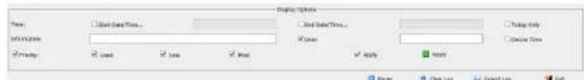
text_image
Display options Load Date/Time... Load Date/Time... Save Only Delete Time Use Load Use Load Use Apply OK| Field Example | |
| Time | The Time filter settings allow you to display only those records that occurred at a specific time. Below are the options.Today Only – Check the Today Only checkbox and click the Apply button to display only those events that occurred on today's date.Device Time – Shows the events according to the time configuration on the switch.Start Date/Time – Check the Start Date/Time checkbox and click in the field to the right of it to bring up a calendar that allows you to select a desired date and time. Click the Apply button to display all of the events that occurred between the date/time entered into the Start Date/Time field and the present date/time.End Date/Time – This setting works in conjunction with the Start Date/Time field. Check the Start Date/Time checkbox and click in the field to the right of it to bring up a calendar that allows you to select a desired date and time. Check the End Date/Time checkbox and click in the field to the right of it to bring up a calendar that allows you to select a desired date and time. Click the Apply button to display all of the events that occurred between the date/time entered into the Start Date/Time field and the date/time entered into the End Date/Time field. |
| Information | The Information field allows you to type in a key word or string, and display only those records that contain the search term. Simply type in a search term and click the Apply button. |
| User | The User field allows you to type in a user name, and display only those records that contain the text that you entered in the User field. To filter by User, you must check the User checkbox, type in a search term, and then click the Apply button. |
| Priority | The Priority fields allow you to filter by the Priority of the event being recorded; Least, Less or Most. To filter by Priority, check the Priority checkbox, then check the Priority level checkbox(es) that you wish to filter by, and then click the Apply button. |
| Reset | Click the Reset button at any time to clear any filter settings that were entered and display all events. |
| Exit Click the Exit button to close the Filter settings. | |
Notification Settings
The Notification Settings sub-section allows you to select which events are sent out to SNMP, SMTP and SysLog servers. Simply check the checkboxes in the rows of the events that you want notifications sent out for, and in the column(s) of the methods you want them to be sent to. When checked, the corresponding event notification will be sent using the corresponding method. Note: Notifications default with an "X", which means they are disabled. Click on a notification box to mark it with a check, enabling it. You can check multiple boxes at the same time using the [Shift] or [Ctrl] keys. To highlight a group of consecutive ports, start by highlighting the first port, hold down the [Shift] key, and then highlight the last port that you wish to highlight. All ports from the first one you highlighted to the last will be highlighted. You can then click on any of the permission checkboxes to change that permission for all of the highlighted ports. To highlight multiple non-consecutive ports, start by highlighting the first port, hold down the [Ctrl] key, and then highlight each additional port one by one while continuing to hold down the [Ctrl] key. When all of the desired ports are highlighted, click on any checkbox to change that permission for all of the highlighted ports.
OSD Operation (continued)
Maintenance
The Maintenance section is used to upgrade the B064-Series KVM Switch's firmware, as well as the firmware of the Server Interface Units (SIUs) used to connect its ports to the installed devices.
Note: Super Administrators are the only users who are guaranteed access to the Maintenance section of the KVM. Administrators and Users can only access this function if they are given permission.
The Main Screen
The Maintenance section can be used to upgrade the KVM and SIU firmware, backup/restore system configuration and account information, ping network devices, and restore the KVMs default values. When selected, the Maintenance section opens with the Upgrade Main Firmware subsection displayed.
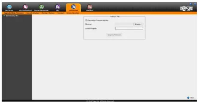
text_image
PTC-Scale Get Multiple Smart Management Lab Resources Download TAPOLATE SOPR-300 PC Other Files File Path Format File Name: Browse... Upload Progress: Upgrade Format OKUpgrade Main Firmware
The Upgrade Main Firmware sub-section is used to upgrade the firmware of the KVM switch. As firmware upgrades become available, they can be found on www.triplite.com/support. To upgrade the KVM firmware, follow the steps below.
- Go to www.tripplite.com/support to download the most current firmware and save it to a computer that is not connected to the KVM switch.
- Logon to the OSD, and navigate to the Maintenance section, which will open with the Upgrade Main Firmware sub-section page displayed.
- By default, the Check Main Firmware Version box is checked, which causes the KVM to check to see if the current firmware is newer than that of the firmware file you are using to upgrade the KVM. If the current version is newer, you will not be allowed to continue with the upgrade. If you wish to perform a firmware upgrade without checking to see if the current firmware version is newer than the upgrade file, simply uncheck this checkbox.
- Click the Browse button, and then navigate to and select the firmware upgrade file you downloaded from the Tripp Lite website. When selected, the Upgrade Firmware button becomes active.
- Click the Upgrade Firmware button to begin the firmware upgrade. As the upgrade proceeds, progress is shown in the Upload Progress bar.
- When the upload is complete, a pop-up appears stating System will reboot in a few seconds. The KVM switch will reboot (this may take a few minutes), and the upgrade will be complete. In the event of a firmware upgrade failure, see the Main Firmware Upgrade Recovery section below.
Main Firmware Upgrade Recovery
Should the KVM firmware upgrade procedure fail, and the switch becomes unusable, follow the steps below to restore the KVM.
- Power off the KVM.
- Press and hold the Reset switch on the front of the unit.
- Power on the KVM while holding down the Reset switch.
- The KVM will be restored to the originally installed firmware version. You will now be able to access the KVM switch and try upgrading the firmware again.
OSD Operation (continued)
Maintenance (continued)
Upgrade Adapters
In addition to upgrading the KVM firmware, the Maintenance section allows you to upgrade the firmware of the connected SIUs. The firmware upgrade file for the master KVM also contains the firmware for the SIUs, so you do not need separate files for each SIU. Once you have uploaded the most current KVM firmware, the most current SIU firmware is available via the Upgrade Adapters sub-section.
Note: Only those SIUs that are directly connected to the master KVM switch can be upgraded. SIUs that are connected to cascaded KVMs will not be upgradeable via the master KVMs Maintenance section.
To upgrade the firmware to the connected STUs, follow the steps below.
- Logon to the OSD, and navigate to the Maintenance section, which will open with the Upgrade Main Firmware sub-section page displayed. Select the Upgrade Adapters sub-section. The Upgrade Adapters page opens, with a list of KVM ports displayed, and the model number and firmware version number of the connected SIUs listed to the right of the port number.
- By default, the Check Adapter Firmware Version box is checked, which causes the KVM to check to see if the current firmware is newer than that of the firmware file you are using to upgrade the SIUs. If the current version is newer, you will not be allowed to continue with the upgrade. If you wish to perform a firmware upgrade without checking to see if the current firmware version is newer than the upgrade file, simply uncheck this checkbox.
- Click the Adapter Firmware Info button to display the most current SIU firmware versions available on the KVM switch. Compare this information with the firmware version numbers displayed in the Upgrade Adapters list. If the version number displayed next to the connected SIUs is older than that in the Adapter Firmware Info list, you should upgrade the firmware.
- Check the checkbox next to each SIU you wish to upgrade. Check the master KVM checkbox to automatically check all SIUs at once.
- Click the Upgrade Adapters button to begin the firmware upgrade. As the upgrade proceeds, progress is shown in the Status column.
- When the upgrade is finished, the Status column will display the text Upgrade Successful. In the event of a firmware upgrade failure, see the SIU Firmware Upgrade Recovery section below.
SIU Firmware Upgrade Recovery
Should the STU firmware upgrade procedure fail, and the STU becomes unusable, follow the steps below.
- Unplug the SIU from the computer/server it is connected to.
- Slide the Firmware Upgrade Recovery switch (located next to the Cat5 connector) to the Recover position.
- Plug the SIU back into the computer/server.
- Start the SIU firmware upgrade procedure again.
- After the SIU has been successfully upgraded, unplug it from the computer/server, slide the Firmware Upgrade Recovery switch to the Normal position, and plug it back in.
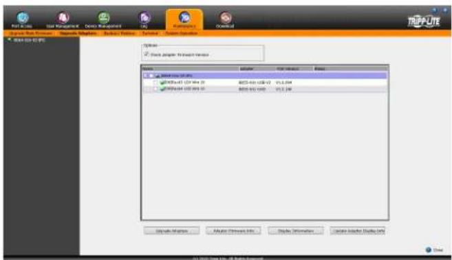
text_image
PostScript User Management Device Management Auto Automotive Download Options Options Search Adapter to Search Window Name: Imported Version: Microsoft Windows 2017-03-01 (C:\Users\Windows\2017-03-01) Microsoft Windows 2017-03-01 (C:\Users\Windows\2017-03-01) Microsoft Windows 2017-03-01 (C:\Users\Windows\2017-03-01) Browse... Browse... Browse... Browse... Browse... Browse... Browse... Browse... Browse... Browse... Browse... Browse... Browse... Browse... Browse... Browse... Browse... Browse... Browse... Browse... Browse... Browse... Browse... Browse... Browse... Browse... Browse... Browse... Browse... Browse... Browse... Browse... Browse... Browse... Browse... Browse... Browse... Browse... Browse... Browse... Browse... Browse... Browse... Browse... Browse... Browse... Browse... Browse... Browse... Browse... Browse...OSD Operation (continued)
Maintenance (continued)
Backup/Restore
The Backup/Restore subsection allows you to backup and restore the KVM switch configuration and user profile information.
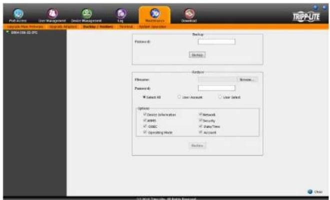
text_image
File Access User Management Device Management Log Resources Download Upgrade Mode Numbers Upgrade Amounts Backup / Numbers Services System Options TRIPP-LITE 0064-038-02-DPG Backup Location Password: Select All User Account User Select Options Device Information Access CODEC Operating Mode Network Security Data/Time Account Balance © 2014 Tripp-LITE. All rights reserved. ClearBackup
To create a backup of the KVM switch, follow the steps below.
- Key in a password in the Password field. Note: Setting a password is optional. If you do not wish to use a password, you can skip this step.
- Click the Backup button.
- A pop-up appears asking you to save the backup file. Browse to a desired location on your computer to save the file to.
Restore
To restore the KVM switch using a backup file, follow the steps below.
- Click on the Browse button to the right of the filename field, and then navigate to and select the backup file.
- If you set up a password when creating the backup file, enter it in the Password field.
- Select as many of the options that are presented as you wish to restore, and then click the Restore button. Once complete, a message appears to inform you that the procedure succeeded.
Terminal
Terminal provides a command line to execute options using a terminal interface. Type a command in the window and hit [Enter] to execute it.
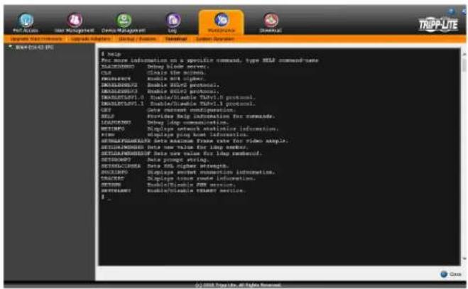
text_image
TRAP-LITE Log Active Management - Upgrade Active - Status / Status - Summary - Summary Description BRA-014-02.07ENew
For More Information on a specific command, type MEL command plane XIAA010000: Debug block server. CST: Clear static action. PHIACMCC: double bit register. KHA000000: Double GluO protocol. KHA000000: Double GluO protocol. KHA000000: Double/Disable Thy01.6 protocol. KHA000000: Double/Disable Thy01.5 protocol. SET: Get element configuration. SET: Provide help information for commands. TERRAMOS: Debug long communication. NETIMPO: Displays network statistics information. KIME: Update long link information. SHEMPLRPLMDATE Beta maximum frame rate for video audio. SHEMPLRMDATE Beta max value for long signal. SHEMPLRMDATE Beta max value for long parameters. SETICOMPT: Data prompt string. SETICOMPT: Data 96 higher values. ANOLVO: Displays smart connection information. CRACKER: Display touch remote information. SETMOS: Double/Disable key service. Settreatment: mobile/Disable key service. F_Available commands include:
Note: The B064-008-01-IPG & B064-016-01-IPG will not have the SETMAXFRAMERATE.
- BLADEDEBUG => Debug blade server.
- CLS => Clears the screen.
- ENABLERC4 => Enable RC4 cipher.
- ENABLESSLV2 => Enables SSLv2 protocol.
- ENABLESSLV3 => Enables SSLv3 protocol.
- ENABLETLSV1.0 => Enable/Disable TLSv1.0 protocol
- ENABLETLSV1.1 => Enable/Disable TLSv1.1 protocol
- GET => Gets current configuration.
- HELP => Provides Help information for commands.
- LDAPDEBUG => Debug s ldap communication.
• NETINFO => Displays network statistics information. - PING => Displays ping host information.
- SETMAXFRAMERATE => Sets maximum frame rate for video sample.
- SETLDAPMEMBER => Sets new value for ldap member.
- SETLDAPMEMBEROF => Sets new value for ldap memberof.
- SETPROMPT => Sets prompt string.
- SETSSLCIPHER => Sets SSL cipher strength.
- SOCKINFO => Displays socket connection information.
- TRACERT => Displays trace route information.
- SETSSH => Enable/Disable SSH service.
- SETTELNET => Enable/Disable TELNET service.
OSD Operation (continued)
Maintenance (continued)
System Operation
The System Operation sub-section allows you to clear port names, and reset the KVM configuration settings to their default values.
The functions available in the System Operation page are explained in the table below.
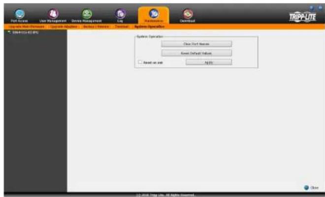
text_image
Port Access Use Management Service Management Log Maintenance Download TrIPP-LITE System Operation Clear Port Status Event Default Value Read on Web Apply Close © 2018 TrIPP-LITE, All rights reserved.| Field Example | |
| Clear Port Names | Click this button to clear all of the port names on the installation and restore them to their default values. Upon clicking this button, you will be prompted to confirm that you wish to clear all port names. Click Yes to proceed. |
| Reset Default Values | Click this button to undo all configuration changes that have been made to the KVM, and restore them to the factory default settings. This does not affect port names, account information or network information. Upon clicking this button, you will be prompted to confirm that you wish to proceed. Click Yes to proceed. |
| Reset on Exit | Check this box and click the Apply button to have the KVM switch reset itself and implement all new settings upon logging out. (Following the reset, allow approximately 30 to 60 seconds before logging back into the KVM.)If you change the IP address of the KVM, the Reset on Exit checkbox is automatically checked. To prevent the KVM from resetting and saving the new IP address, uncheck this box. Note: Un-selecting this checkbox will only cause the new network settings to be ignored for one logout. When you log back in, the changes you made still appear in the Network settings fields, and the Reset on Exit checkbox is once again checked. To ensure that these settings don't get changed to something you don't want, always make sure that you leave the Network settings page with the correct information entered in. |
Download
The Download icon is used to download non-browser AP versions of the Windows and Java Clients, as well as the Log Server. Selecting this tab will open a drop-down list of the programs that are available for download.
Note: If you have not been given access to one of these applications, you will not be able to download it.
Click on the Download icon and select the program you want to download. Save it to a convenient location on your hard disk and run it from there.
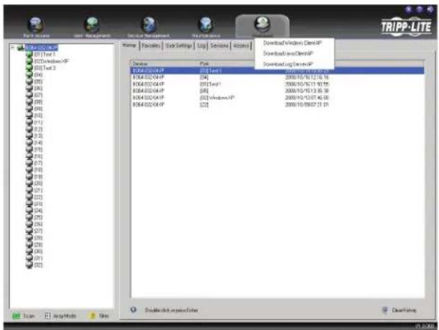
text_image
TRIPP-LITE File Access Get Management Service Management Performance Download Windows Open-HP Downloaded Open-HP Downloading Window Open-HP Storage File Settings Log Settings Access 1064.032.041.PF [04] 1064.032.041.PF [011]cmd1 1064.032.041.PF [08] 1064.032.041.PF [032]windows.PF 1064.032.041.PF [22] 2008/10/16/17:30:55 2008/10/16/17:30:55 2008/10/16/17:30:55 2008/10/16/17:30:55 2008/10/16/17:30:55 2008/10/16/17:30:55Remote Session Operation
After you have successfully logged in (see Logging Into the B064-Series KVM Switch section), the B064-Series KVM Switch OSD Main Page appears with the Port Access tab selected:
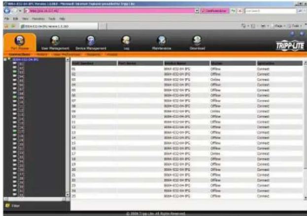
text_image
TRIPP-LITE User Management Device Management Log Performance Download File Edit View Tools Help 01 02 03 04 05 06 07 08 09 10 11 12 13 14 15 16 17 18 19 20 21 22 23 24 25 26 27 28 29 30 31 32 33 34 35 36 37 38 39 40 41 42 43 44 45 46 47 48 49 50 51 52 53 54 55 56 57 58 59 60 61 62 63 64 65 66 67 68 69 70 71 72 73 74 75 76 77 78 79 80 CTR-11-04-PC 01 02 03 04 05 06 07 08 09 10 11 12 13 14 15 16 17 18 19 20 21 22 23 24 25 © XRS Top Inc. All rights reserved.Note: The AP Client and Local Console versions feature a Control Panel in the top center of the screen that appears when scrolled over with the mouse. The web browser version's Control Panel is only available when a port has been accessed. (See Control Panel section for details.)
All the ports that a user is permitted to access are listed in the Port Selection panel at the left of the page. Ports to which users do not have access will not be displayed in their OSD. Double-click a port icon to access the device attached to it. Once you switch to a port, its screen displays on your monitor. Depending on whether you have Full Access or View Only access to the port, you may or may not be able to operate the remote computer using your keyboard and mouse.
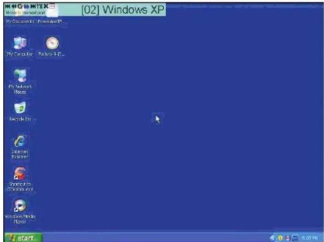
text_image
[02] Windows XP My Computer - Windows XP... My Network Blogs Recycle Bin Internet E3.0 port Shooting to C:\Users\nc Windows Media Fines... startControl Panel
The Control Panel is provided as a way for the user to optimize and control the remote session. Regardless of whether you initiated a remote session via the Windows or Java browser and non-browser clients, the control panel and its functionality remain the same. To display the Control Panel, hover your mouse pointer over the top-center of the remote screen.
The Control Panel consists of an icon bar at the top and two text bars at the bottom. When the mouse pointer is hovered over an icon, the description of the icon is displayed in the text bar. When the mouse pointer is not over an icon, the text bars display the video resolution of the selected computer and the IP address of the KVM switch. You can drag the control panel to any location on the remote screen by hovering over the text bar, and then clicking-and-dragging it. Each of the icons contained in the Control Panel and their functionality is explained in the sections that follow.
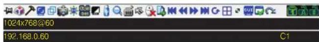
text_image
1024x768@60 192.168.0.60 C1
Always on Top / Auto Hide – Click this button to toggle between displaying the control panel all the time, or to allow it to disappear after a few seconds of inactivity.

Hotkeys / Macros – The Hotkeys / Macros page allows the user to use Hotkeys and Macros to manipulate the remote computers. The user can enable/disable hotkeys, and create/edit User Macros and System Macros. The sections that follow describe how these features work.
Remote Session Operation (continued)
Control Panel (continued)
Hotkeys
Various configuration actions related to the keyboard, video and mouse can be performed via hotkey combinations. The Hotkey setup utility is accessed by clicking on the Hotkey / Macros icon and then clicking on the Hotkeys button at the top of the screen. The Hotkeys screen displays the available hotkeys and their corresponding hotkey combinations.
By default, the only hotkeys that are enabled are the Exit Remote Location and Substitute Alt Key hotkeys. To enable/disable a hotkey, simply check/uncheck the box to the left of it. To change a hotkey's command sequence, follow the steps below.
- Highlight the desired hotkey and click on the Set Hotkey button.
- Key in the desired hotkey combination, one key at a time. The keys will be displayed in the hotkey column as they are entered. Note: Clicking the Cancel button will cancel the recording process. Clicking on the Clear button will delete any keys that you entered while keeping the recording process active.
- When finished entering the hotkey sequence, click on the Save button.
Note: Clicking the Reset button will restore all of the default hotkey command sequences, and enable/disable defaults. You can use the same function keys for more than one hotkey command sequence, as long as the first key is not the same. For example, you can use [F1, F2, F3] for one action and [F2, F1, F3] for another, but you cannot use [F1, F3, F2] once [F1, F2, F3] has been used.
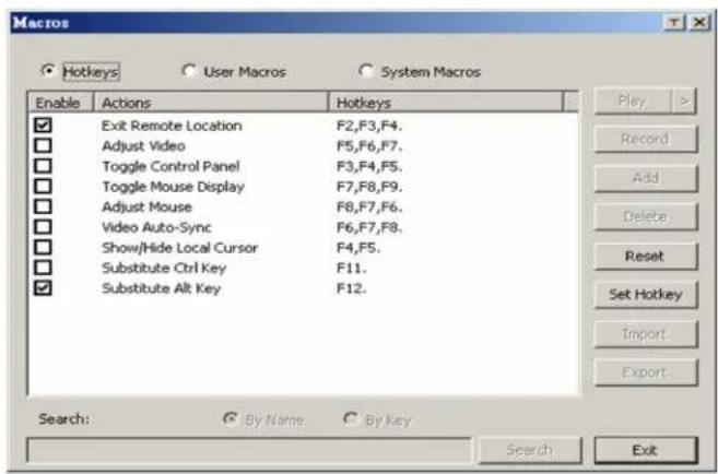
text_image
Macros Hotkeys User Macros System Macros Enable Actions Hotkeys ✓ Exit Remote Location F2,F3,F4. □ Adjust Video F5,F6,F7. □ Toggle Control Panel F3,F4,F5. □ Toggle Mouse Display F7,F8,F9. □ Adjust Mouse F8,F7,F6. □ Video Auto-Sync F6,F7,F8. □ Show/Hide Local Cursor F4,F5. □ Substitute Ctrl Key F11. ✓ Substitute Alt Key F12. Play > Record Add Delete Reset Set Hotkey Import Export Search: By Name By key Search ExitThe table below lists the default hotkeys, along with a description of their functions and their default command sequences.
| Hotkey Description Command Sequence | ||
| Exit Remote Location | Closes you out of a remote session. [F2, F3, F4] | |
| Adjust Video Opens | the Video Settings screen. [F5, F6, F7] | |
| Toggle Control Panel | Toggles the Control Panel off and on. When off, you will not be able to access the control panel. | [F3, F4, F5] |
| Toggle Mouse Display | Toggles the local mouse pointer between an arrow and a tiny circle. Note: This Hotkey appears when accessing the WIN Client only. | [F7, F8, F9] |
| Adjust Mouse | When the local and remote mouse pointers go out of sync, this command brings them back together again. | [F8, F7, F6] |
| Video Auto-Sync Performs a video auto-sync. [F6, F7, F8] | ||
| Show/Hide Local Cursor | Toggles the local mouse pointer on/off. [F4, F5] | |
| Substitute Ctrl Key | By default, hotkey combinations that use the Ctrl key, such as [Ctrl, Alt, Delete], get sent to the local computer. This hotkey allows you to set a substitute Ctrl key that can be used for the remote computer. | F11 |
| Substitute Alt Key | By default, hotkey combinations that use the Alt key, such as [Ctrl, Alt, Delete], get sent to the local computer. This hotkey allows you to set a substitute Alt key that can be used for the remote computer. | F12 |
Remote Session Operation (continued)
Control Panel (continued)
User Macros
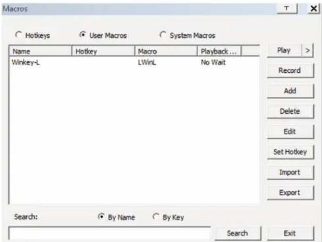
text_image
Macros Hotkeys User Macros System Macros Name Hotkey Macro Playback ... Winkey-L LWinL No Wait Play > Record Add Delete Edit Set Hotkey Import Export Search: By Name By Key Search ExitThe User Macros page allows you to add macros to the KVM switch that can be performed on any of the connected computers using the Macro List feature of the control panel. (See Macro List section under Control Panel in Remote Session Operation for details.) By default, the User Macros page is displayed when the Hotkeys / Macros icon is clicked on. To display the page when it isn't selected, click on the User Macros button at the top of the Hotkeys / Macros screen.
To create a macro, follow the steps below.
- Click the Add button on the right side of the screen.
- In the name field that appears, key in a name for the macro you are adding.
- With the new macro highlighted, click the Record button on the right side of the screen. Recording will begin and the following panel will be displayed in the upper-left corner of the remote screen.

text_image
Pause Done Cancel Show- Enter in the macro hotkey sequence and then click the Done button. You will be returned to the User Macros screen, with your macro name and hotkey combination added to the list. Repeat this procedure for any additional macros you wish to create. Note: Clicking the Pause button will pause/unpause the recording of the hotkey sequence. Clicking the Cancel button will cancel the recording of the hotkey sequence. Clicking the Show button will display the hotkeys as they are entered.
System Macros
The System Macros page allows you to add macros to the KVM switch that can be performed automatically upon closing a session. For example, you can create a macro that sends the Winkey-L combination, causing a computer's login page to come up the next time it is accessed. To display the System Macros page when it isn't selected, click on the System Macros button at the top of the Hotkeys / Macros screen.
To create a macro, follow the steps below.
- Click the Add button on the right side of the screen.
- In the name field that appears, key in a name for the macro you are adding.
- With the new macro highlighted, click the Record button on the right side of the screen. Recording will begin and the following panel will be displayed in the upper-left corner of the remote screen.

text_image
Pause Done Cancel Show- Enter in the macro hotkey sequence and then click the Done button. You will be returned to the System Macros screen, with your macro name and hotkey combination added to the list. Repeat this procedure for any additional macros you wish to create. Note: Clicking the Pause button will pause/unpause the recording of the hotkey sequence. Clicking the Cancel button will cancel the recording of the hotkey sequence. Clicking the Show button will display the hotkeys as they are entered.
Once system macros are created, they are available to be assigned to ports, with only one macro allowed per port. (See the Port Configuration section under OSD Operation for details on assigning system macros.)
Remote Session Operation (continued)
Control Panel (continued)
Video Settings – The Video Settings screen allows you to adjust the placement and picture quality of the remote screen. The quality of the image display has a direct affect on the keyboard and mouse response time. Higher quality video results in more information being transferred over the network, which can cause slow keyboard and mouse response time in slower networks. Click this icon to open the Video Settings screen.
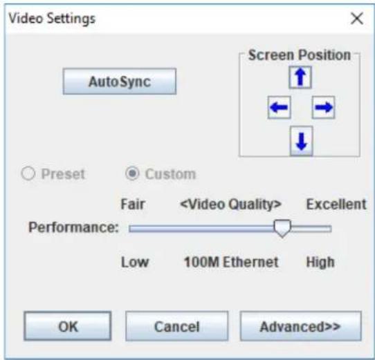
text_image
Video Settings AutoSync Screen Position ↑ ← → ↓ ○ Preset ● Custom FairThe table below describes the contents of the Video Settings screen:
| Setting Description | |
| Screen Position | Adjust the horizontal and vertical position of the screen using the Screen Position arrows. |
| Auto Sync | Click this button to automatically detect the vertical and horizontal position settings of the remote screen. If the local and remote mouse pointers are not synced, performing this function will normally bring them back into alignment. If Auto Sync fails to align the screen properly, use the Screen Position arrows to make manual adjustments. |
| RGB | Move the RGB (Red, Green, Blue) slider bars to adjust the corresponding color component of the video image. Check the Set to Grayscale checkbox to display the video of the remote computer in black and white. If the remote keyboard and mouse response time is slow or choppy, checking the Set to Grayscale option can speed them up. |
| Gamma | This section allows you to adjust the video display's gamma level. This function is discussed in detail in the Gamma Adjustment section following this table. |
| Performance | Use the slide bar to select the Internet connection type used by the local client computer. The switch will use that selection to automatically adjust the Video Quality settings to optimize the quality of the video display. Since network conditions vary, if none of the preset choices appear to work well, you can select Advanced and use the Video Quality slider bar to adjust the settings to suit your conditions. |
| Video Quality | Drag the slider bar to adjust the overall quality of the video of the remote computer. On slower networks, lowering the video quality can help improve keyboard and mouse response time. |
| Enable Refresh | The remote screen can be set to be redrawn every 1 to 99 seconds, eliminating unwanted artifacts that would otherwise remain on the screen. Click the Enable Refresh checkbox to activate this feature, and then enter in the desired refresh rate. |
| Transparency | Adjusts the transparency of the toolbars displayed by the Windows and Java clients. Move the slider bar until the transparency is set to the desired level. |
Remote Session Operation (continued)
Control Panel (continued)
Gamma Adjustment
If it is necessary to correct the gamma level for the remote computer, use the Gamma function in the Video Settings screen. Under the Basic configuration, the gamma drop-down list includes ten preset and four user defined gamma levels to choose from. Simply select the desired setting from the drop-down list. To set your own gamma levels, follow the instructions below.
- Click the Advanced button to bring up the gamma adjustment settings.
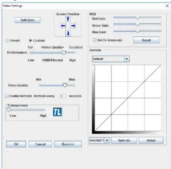
text_image
Video Settings Auto Sync Screen Position RGB Red Gain: Green Gain: Blue Gain: Set To Grayscale Reset Preset Custom Fair-
Click and drag the diagonal line at as many points as you wish to achieve the display output you desire. Click the Reset button at any time to abandon changes and return to the default gamma settings. Click the Cancel button to abandon changes and close the Video Settings screen.
-
To save the new gamma settings, select a user defined setting from the drop-down list and click the Save button. Your gamma settings will be saved to the selected user defined option.

Video Auto Sync – Click this icon to have the vertical and frontal offset values of the remote screen automatically detected synchronized with the local screen. Note: If the local and remote pointers are out of sync, performing a video auto sync will really bring them back into alignment. If the video auto sync fails to sign the screen properly, use the screen position arrows in the Settings screen to make manual adjustments.

Screen Mode – Click this icon to toggle Full Screen mode on/for those accessing the KVM via one of the Windows clients, clicking this icon will toggle Keep Screen Size on/off. When Screen Size is enabled, turning on Full Screen mode will not be the size of the remote screen. For example, remote screens are set to resolutions lower than that of the local monitor will be yed as a box inside of the local display. When both Keep Screen and Full Screen Mode are enabled, the remote screen will be yed as a box with a black background. If Keep Screen Size is set and Full Screen Mode is enabled, the screen will be stretched the entire local monitor. Note: Keep Screen Size can only be set on/off when using one of the Windows clients. When using of the Java clients, Keep Screen Size is always enabled.

Snapshot – Clicking this icon will take a screenshot of the computer and save it to the local computer. By default, shots are saved to the local computer's desktop. The file type, by and location can be changed via the Customize Control Panel

Message Board – The B064-Series KVM supports multiple logins, which can give rise to access conflicts. To alleviate this item, a message board feature has been provided that allows users communicate with each other.
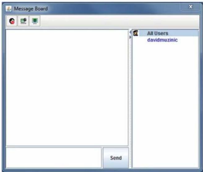
text_image
Message Board All Users davidmuzinic SendRemote Session Operation (continued)
Control Panel (continued)
The buttons on the button bar at the top of the message board are toggles. The actions for each of these buttons are described in the table below.
Button Function
 | Enable/Disable Chat – When disabled, this icon displays next to the disabled user's name in the User List panel of all users' message boards. Messages directed to the disabled user are not displayed on the message board. The button is shadowed when chat is disabled. |
 | Occupy/Release Keyboard/Video/Mouse – When you occupy the KVM, other users cannot see the video, and cannot input keyboard or mouse data. A prompt will come up on the locked out users' monitor stating which user has occupied the KVM. The button in the message board is shadowed and this icon displays next to the occupying user's name in the User List of all users' message boards. |
 | Occupy/Release Keyboard/Mouse – When you occupy the KVM, other users can see the video, but cannot input keyboard or mouse data. The button is shadowed and this icon displays next to the occupying user's name in the User List of all users' message boards. |
User List Panel
- To hide/unhide the User List panel, click on the arrows in the panel separator.
- The names of all the logged in users appear in the User List panel. Select the names of the users that you wish to communicate with before sending your message.
- If a user has disabled chat, its icon displays before that user's name.
- If a user has occupied the KVM or the KM, the corresponding icon displays before that user's name.
Compose Panel
Type your message into this panel and then click the Send button or press the [Enter] key to post the message to the message board. Note: You must select the user that you want to communicate with from the user list. To send a message to all users, simply click All Users in the user list.
Message Display Panel
Messages that users post to the board, as well as system messages, display in this panel. If you disable chat, messages that get posted do not appear.

Ctrl - Alt - Delete - Click this icon to send the [Ctrl, Alt,
Delete] command to the remote computer.

Set to Grayscale – Click this icon to display the remote video
in black and white. On slower networks, displaying the remote video in black and white can help improve keyboard and mouse response time.

Virtual Media – The Virtual Media function allows a drive,
folder, image file or removable disk on a user's system to be accessible on the remote server. The following media are supported via the KVMs Virtual Media functionality.
Browser and non-Browser Windows Client
- IDE CD-ROM/DVD-ROM Drives – Read Only
- IDE Hard Drives – Read Only
- USB CD-ROM/DVD-ROM Drives – Read Only
- USB Hard Drives – Read/Write*
- USB Flash Drives – Read/Write*
- USB Floppy Drives – Read/Write
- USB Card Readers
- USB Fingerprint Readers
• ISO Files – Read Only - Folders – Read/Write
* These drives can be mounted either as a Drive or as a Removable Disk. Mounting as a Removable Disk allows the user to boot the remote server if the disk contains a bootable OS. If the disk contains more than one partition, the remote server can access all of the partitions.
Browser and non-Browser Java Client
- ISO Files – Read Only
- Folders – Read/Write
USB Ports on Front Panel of KVM Switch
- IDE CD-ROM/DVD-ROM Drives – Read Only
- IDE Hard Drives – Read Only
- USB CD-ROM/DVD-ROM Drives – Read Only
- USB Hard Drives – Read/Write*
- USB Flash Drives – Read/Write*
• USB Floppy Drives – Read/Write - USB Card Readers
• USB Fingerprint Readers
* These drives can be mounted either as a Drive or as a Removable Disk. Mounting as a Removable Disk allows the user to boot the remote server if the disk contains a bootable OS. If the disk contains more than one partition, the remote server can access all of the partitions.
Note: The Virtual Media function is only active for computer/servers that are connected to the KVM switch using a B055-001-USB-V2 SIU. Computers connected to a cascaded B064-016 KVM will not be able to use virtual media.
Remote Session Operation (continued)
Control Panel (continued)
Virtual Media
Virtual Media via Remote Session
When accessing a connected computer remotely, you can use media from the computer you are accessing the KVM switch with on the remote computer. You are also able to access media connected to the USB ports on the front of the KVM switch; however, media connected to these ports needs to be mounted via the local console. (See Virtual Media via Local Console section under Control Panel in Remote Session Operation for details.) To access virtual media via remote session, follow the instructions below. Note: When accessing the KVM remotely with a Windows Vista or 7 computer, you must run Internet Explorer as an administrator for virtual media to function properly.
- Click the Virtual Media icon on the control panel to bring up the following screen.
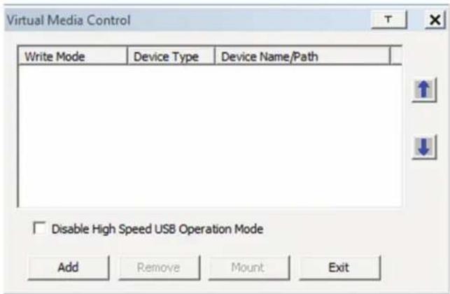
text_image
Virtual Media Control Write Mode Device Type Device Name/Path Disable High Speed USB Operation Mode Add Remove Mount ExitNote: The T button in the upper-right corner brings up a slider bar that allows you to adjust the transparency of the virtual media screen. When you're finished making an adjustment, simply click anywhere on the screen to close the slider bar.
- Click the Add button and then select the desired media from the list of media sources that appears. Each selected media source will allow you to choose the available drive, file, folder or removable disk.
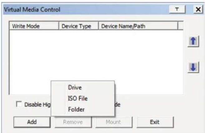
text_image
Virtual Media Control Write Mode Device Type Device Name/Path Drive ISO File Folder Disable Hig Add Remove Mount ExitNote: If your media source is USB 1.1, check the Disable High Speed USB Operation Mode checkbox.
-
Repeat this step to add as many media sources as you want to the Virtual Media screen. To remove a media source from the list, highlight it and click the Remove button. Note: Only 3 media sources can be used at any one time, with the top 3 sources in the list being the active devices. To rearrange the device order, highlight the desired device and use the arrow keys on the right of the screen to move the device up or down in the list.
-
Some media sources are Read Only, whereas others are Read/Write. Those that are Read/Write can be viewed on the remote computer, and can have data from the remote computer added to them. Those that are Read Only can only be viewed. Read Only media sources will be grayed out in the list, not allowing you to check the Enable Write checkbox to the left of the source. Read/Write sources will not be grayed out, and you will be able to decide whether data can be added to them or not. By default, Read/Write sources are displayed with the Enable Write checkbox unchecked, which means that data cannot be added to them. To allow data from the remote computer to be added to a media source, simply check the Enable Write checkbox to the left of it in the list.
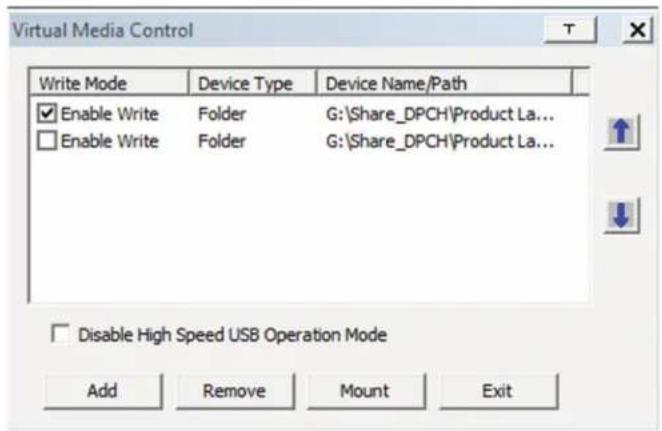
text_image
Virtual Media Control Write Mode Device Type Device Name/Path Enable Write Folder G:\Share_DPCH\Product La... Enable Write Folder G:\Share_DPCH\Product La... Disable High Speed USB Operation Mode Add Remove Mount Exit-
Once all media sources are added, and the desired 3 media sources are at the top of the list, click the Mount button to close the dialog box and open the media sources on the remote computer. Note: Depending on the speed of your network and the size of the media source, it may take 30 seconds or so for the dialog box to close and the media to open on the remote computer.
-
To disconnect the media sources from the remote computer, click on the Virtual Media icon in the control panel.
Remote Session Operation (continued)
Control Panel (continued)
Virtual Media via Local Console
When accessing the KVM via the local console, you can mount media connected to the additional USB ports on the front of the KVM, and access it on the connected computers. After connecting a USB device to one of the USB ports on the front of the KVM, follow the instructions below to mount it to a KVM port and access it via the connected computer.
- Open the OSD and highlight the desired port in the side bar. Right-click on it and select the Mount option.
- A Virtual Media Settings box appears, which is exactly the same as the one found when mounting virtual media remotely, except that it contains a Keep Alive check box. To add a device, click on the Add button to display the list of devices connected to the KVMs front panel, and select the desired device. If your device is USB 1.1, check the Disable High Speed USB Operation Mode checkbox. To keep the device mounted even after the local user logs out, check the Keep Alive checkbox.
- Once mounted, the media device will be accessible both locally and remotely. To unmount the device, right-click on the desired port in the OSD and select the Unmount option.
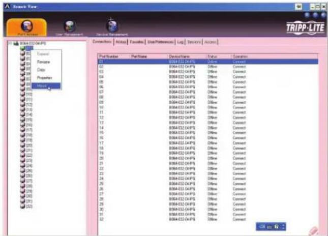
text_image
TRIPP-LITE File Edit View Insert Tools Help Connection: Altip Fashes Use Parameters Log Services Active Port Number Port Name Destination Date Operation 01 02 03 04 05 06 07 08 09 10 11 12 13 14 15 16 17 18 19 20 21 22 23 24 25 26 27 28 29 30 31 32 01 02 03 04 05 06 07 08 09 10 11 12 13 14 15 16 17 18 19 20 01 02 03 04 05 06 07 08 09 10 11 12 13 14 15 16 17 02 03 04 05 06 07 08 09 10 11 12 13 14 15 16 17 18 19 20 21 22 23 24 25 26 27 28 29 30 31 32
Zoom - Click this icon to zoom in on the remote display.
You can choose to display the screen at 100%, 75%, 50% or 25%. Checking the 1:1 checkbox will keep the screen contents sized in a 1:1 ratio, regardless of whether you choose to display the remote session at 100%, 75%, 50% or 25%.

On-Screen Keyboard - The B064-Series KVM switch
features an on-screen keyboard, available in multiple languages, with all of the standard keyboard keys for each language. Click this icon to display the on-screen keyboard.
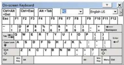
text_image
On-screen Keyboard Ctrl+Alt +Del Ctrl+Esc Alt +Tab English US Esc F1 F2 F3 F4 F5 F6 F7 F8 F9 F10 F11 F12 ~ ! @ # $ % ^ & * ( ) - + ←Backspace - 1 2 3 4 5 6 7 8 9 0 = = Tab Q W E R T Y U I O P { } Caps Lock A S D F G H J K L : * Shift Z X C V B N M < > ? Shift Ctrl Win Key Alt Alt Win Key Menu Ctrl- To switch to a different language keyboard, open the drop-down list in the upper-right of the on-screen keyboard and select the desired language.
- To expand the keyboard to include the number pad, click on the arrow icon to the right of the language drop-down menu.
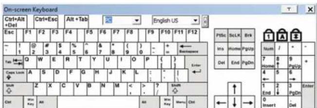
text_image
On-screen Keyboard Ctrl+Alt +Del Ctrl+Esc Alt+Tab English US Esc F1 F2 F3 F4 F5 F6 F7 F8 F9 F10 F11 F12 - 1 # $ % & * ( )+ + ← 1 2 3 4 5 6 7 8 9 0 - Tab Q W E R T Y U I O P { } Casp Locus A S D F G H J K L : " | ← Sum Z X C V B N M < > ? Width Ctrl power key All All power key menu Ctrl PISc Selx Brk Ins Homo PgUpp Home 8 9 Del End PgDm 7 Home ↑ 4 5 6 1 2 3 Enter End PgDm 0 Insert Del
Mouse Pointer - Click to choose how the local and remote pointers are displayed. You can choose to display Dual mouse pointers, Crosshairs mouse pointers, the local mouse pointer as a lot (not available via Java), or only the remote mouse pointer. Dual mouse pointers display both local and remote mice as arrows. Crosshairs mouse pointers display the local mouse as a cross, and the remote mouse pointer as an arrow. When displaying the local mouse pointer as a tiny dot, the remote mouse pointer will be displayed as an arrow.

Mouse Sync Mode – Click to toggle between automatic manual mouse sync modes. When set to automatic, a green mark appears on the icon. When set to manual, a red x appears the icon. Note: This icon is only active on computers that are set to the KVM using a USB SIU. The auto sync functionality supports Windows and Mac (G4 and higher), and the adapter rate OS setting must be set to Windows or Mac. (See Port Party section under Port Configuration in OSD Operation for its on the adapter attribute OS setting.)
Mac and Linux Considerations
A second Mac auto sync setting is available for Mac OS X 10.4.11 and higher. If you find that enabling automatic mouse sync per the instructions above does not provide satisfactory results, right-click the mouse in the black text area of the control panel, highlight the Mouse Sync Mode option and select Automatic for MAC 2.
Although Linux does not support automatic mouse sync mode, there is an additional setting in the Mouse Sync Mode drop-down menu for Redhat AS3.0 systems. If you are having difficulty synchronizing the local and remote mice, try right-clicking the mouse in the black text area of the control panel, highlight the Mouse Sync Mode option and select Automatic for Redhat AS3.0.
Remote Session Operation (continued)
Control Panel (continued)
Manual Mouse Synchronization
If the local mouse pointer goes out of sync with the remote system's mouse pointer, there are a number of methods to bring them back into sync.
Before trying any mouse synchronization procedures, it is always a good idea to ensure that you go to your Mouse Properties Settings and set them according to the instructions that follow. The Mouse Properties Settings should be set on the computers attached to the B064-Series KVM Switch, not the computer you are using to access it. Note: In order for the local and remote mice to synchronize, you must use the generic mouse driver supplied with the MS operating system. If you have a third party driver installed - such as one supplied by the mouse manufacturer - you must remove it.
Windows 2000:
- Open the Mouse Properties dialog box
- Click the Motion tab
- Set the mouse speed to the middle position (6 units in from the left)
- Set the mouse acceleration to None
Windows XP and later:
- Open the Mouse Properties dialog box
- Click the Pointer Options tab
- Set the mouse speed to the middle position (6 units in from the left)
- Disable Enhance Pointer Precision
Sun / Linux:
Open a terminal session and issue the following command:
Sun: xset m 1
Linux: xset m 0
Mouse Synchronization Procedures
If you are having syncing problems after adjusting the mouse properties, try the following methods to help synchronize the local and remote mouse pointers. Note: Mouse synchronization may require several seconds to take effect. Wait for 15 to 30 seconds to ensure that the mouse has had enough time to sync.
- When in a remote session, move the mouse pointer to the upper-center of the screen to open the control panel, and then move it back into the remote screen. The mouse pointers should align.
- Click the Video Auto Sync icon in the control panel. In most cases, the local and remote mouse pointers will sync following the video auto sync.
- Invoke the Adjust Mouse hotkey command (see Hotkeys section under Control Panel for details). This hotkey command defaults at F8, F7, F6.
- Adjust the video settings to decrease the amount of information being transferred over the network. The less data that is being sent, the faster the response time. In particular, the Quality and Detect Tolerance settings in the Video Settings screen (see Video Settings section under Control Panel for details) can help improve keyboard and mouse response time.
- Go to the Network page in the OSD and reduce the Network Transfer Rate setting. (See Network section under Device Management in OSD Operation for details.)
- Go to the display settings section of the remote computer and lower the video resolution, refresh rate and color settings.
- If the remote computer has a graphic desktop background, change it to a solid color background.
Remote Session Operation (continued)
Control Panel (continued)

Speaker - Click to toggle sound On and Off from the remote to be heard on the client computer's speakers.

Macro List – Click this icon to display a drop-down list of the User Macros (see User Macros section under Control Panel for details) that have been added to the KVM switch. Select a macro to run it on the selected computer.

First Port - Click this icon to skip to the first accessible port on stallation.

Previous Port – Click to skip to the first accessible port prior to currently selected port.

Next Port - Click to skip to the first accessible port after the only selected port.

Last Port - Click to skip to the last port on the installation.

Scan Ports – Click to initiate Auto Scan mode. (See Auto ing section for details.)

Array Mode – Click to initiate Panel Array mode. (See Panel Mode section under The OSD Toolbar for details.)

Cat5 Cable Length - As the length of Cat5 cable between the and connected computer can affect video quality, this setting is needed to compensate for shorter or longer lengths. Click to toggle through the Cat5 cable length options; Short (less than 32 ft. / 10 m), m (between 32 ft. / 10 m and 82 ft. / 25 m) and Long (over 82.5 m). Note: Only applies to the B064-008-01-IPG and B064-01-IPG KVMs.

Open GUI - Click to open the OSD.

Customize Control Panel – Click this icon to bring up the Customize Control Panel screen, which allows you to choose which icons are displayed in the control panel, as well as edit some of its features.
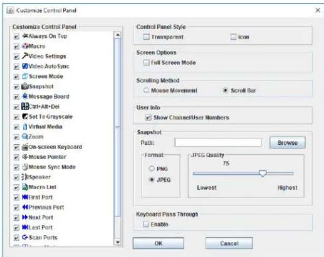
text_image
Customize Control Panel Customize Control Panel Always On Top Macro Video Settings Video AutoSync Screen Mode Snapshot Message Board Ctrl+Alt+Del Set To Grayscale Virtual Media Zoom On-screen Keyboard Mouse Pointer Mouse Sync Mode Speaker Macro List First Port Previous Port Next Port Last Port Scan Ports Control Panel Style Transparent Icon Screen Options Full Screen Mode Scrolling Method Mouse Movement Scroll Bar User Info Show Channel/User Numbers Snapshot Path: Browse Format JPEG Quality 75 Lowest Highest Keyboard Pass Through Enable OK CancelCustomize Control Panel – The box on the left side of the screen displays a list of the available control panel features, with a checkbox next to each one. Check/uncheck a checkbox to display or remove the corresponding features icon from the control panel. By default, all features are included in the control panel.
Control Panel Style – This section allows you to determine how the control panel is displayed when it is dragged out of the default position in the top-center of the screen. Note: There is a second default position for the control panel at the bottom-center of the screen.
- When the Transparent checkbox is checked, dragging the control panel away from one of the default locations will leave it displayed transparently in whatever location it was dragged to.
- When the Icon checkbox is checked, dragging the control panel away from one of the default locations will leave it displayed as an icon in whatever location it was dragged to.
- When both the Transparent and Icon checkboxes are checked, dragging the control panel away from one of the default locations will leave it displayed as a transparent icon in whatever location it was dragged to.
- When neither checkbox is checked, dragging the control panel away from one of the default locations will leave it displayed as normal in whatever location it was dragged to.
- If the control panel is located in either the top-center or bottom-center default locations, checking these checkboxes will have no effect.
Remote Session Operation (continued)
Control Panel (continued)
Screen Options – This section allows you to make Full Screen Mode and Keep Screen Size the default settings when a remote session is activated. Note: Keep Screen Size is not available when using the Java clients.
- Check the Full Screen Mode checkbox to display the remote screen in Full Screen Mode starting with the next time you login to a remote session.
- Check the Keep Screen Size checkbox to enable the Keep Screen Size feature starting with the next time you login to a remote session.
Bus Info – The B064-Series KVM Switch allows multiple users to access the connected computers simultaneously, with each user accessing one bus. In addition, multiple users can log onto the same bus at the same time, and share a remote session. The amount of buses is the same as the total number of simultaneous users. For example, a B064-032-02-IPG allows 3 users (2 remote, 1 local) to simultaneously access connected computers, and therefore has 3 buses. When 3 users are logged on at the same time, each would be accessing the KVM on a separate bus. When a fourth user logs on, they are logged onto the first bus, which they are sharing with the first logged on user.
When the Bus Info checkbox in the Customize Control Panel screen is checked, the bus (channel) being accessed and the number of users on that bus (channel) is displayed in the control panel text bar. For example, C1/2 would signify that you are accessing the connected computers on bus (channel) 1, and there are 2 users currently accessing bus (channel) 1 at the same time.
Snapshot – The Snapshot section allows you to determine where snapshots are sent to, what file type they are saved as; and, if saved as a JPEG, the quality of the JPEG image. Although the Snapshot section is available to both Windows and Java users, the two differ in the types of files that can be saved. The Windows clients allow you to choose between a BMP and a JPEG file, whereas the Java clients allow you to choose between PNG and JPEG.
- Path – To select a location for snapshots to be saved in, click on the Browse button next to the Path field. Navigate to the desired location and select it.
- Format – Check the button of the file type that you want the snapshot to be saved in.
- JPEG Quality – If you select to save snapshots as JPEGs, you can adjust the quality of the JPEG image here. The higher the quality of the image, the larger the file size.
Keyboard Pass Through - When selected, the [Alt, Tab] function will be sent to the remote computer. When it is not selected, the [Alt, Tab] function is sent to the local computer. It is deactivated by default.

Exit - Click this icon to exit the remote session.
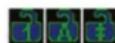
Lock LEDs – These icons display the status of the keyboard Num Lock, Caps Lock and Scroll Lock LEDs. You can click on them to corresponding lock function on/off. When first initiating a remote session, you may have to toggle these off/on to make sure they are with your keyboard.
Remote Session Operation (continued)
The OSD Toolbar
The OSD provides a toolbar to help you control the B064-Series KVM Switch from within the captured port. There are three hotkey combinations that can be used to pull up the OSD Toolbar and/or OSD when in a remote session:
- When in a remote session, hit the hotkey [Scroll Lock] twice to open the OSD Toolbar.
- When in a remote session, hit the hotkey [Scroll Lock] three times to open the OSD.
- When the OSD Toolbar is opened in a remote session, hit the hotkey [Scroll Lock] once to open the OSD.
The OSD Toolbar is shown below:

[01]
Depending on the settings that were selected for ID Display, the Port Number and/or the Port Name display at the right of the toolbar.
Note: When the toolbar displays, mouse input is confined to the toolbar area and keyboard input (other than the Scroll Lock/Control hotkey) has no effect.
The meanings of the toolbar icons are given in the table below:
| Icon Description | |
| Click to skip to the first accessible port on the entire installation without having to invoke the OSD. | |
| Click to skip to the first accessible port previous to the current one without having to invoke the OSD. | |
| Click to begin Auto Scan Mode. The B064-Series KVM Switch automatically switches among the ports that were selected for Auto Scanning in the Port Select and Filter functions. This allows you to monitor their activity without having to switch among them manually. | |
| Click to skip from the current port to the next accessible one without having to invoke the OSD. | |
| Click to skip from the current port to the last accessible port on the installation without having to invoke the OSD. | |
| Click to bring up the OSD. | |
| Click to close the OSD toolbar. | |
| Click to invoke Panel Array Mode. (See Panel Array Mode section under The OSD Toolbar for details.) | |
| As the length of Cat5 cable between the KVM and connected computer can affect video quality, this setting is designed to compensate for shorter or longer lengths. Click to toggle through the Cat5 cable length options; Short (Less than 32 ft. / 10 m), Medium (Between 32 ft. / 10 m and 82 ft. / 25 m) and Long (Over 82 ft. / 25 m). | |
Toolbar Hotkeys
When the Toolbar is displayed, hotkeys can be used to switch between ports. The table below describes what actions can be performed.
| Hotkey Action | |
| ← | Skips from the current port to the first accessible port previous to it. To gain control of the selected port, hit the [Esc] key or click on the X icon in the Toolbar |
| → | Skips from the current port to the first accessible port after it. To gain control of the selected port, hit the [Esc] key or click on the X icon in the Toolbar |
| ↑ | Skips from the current port to the first accessible port on the installation. To gain control of the selected port, hit the [Esc] key or click on the X icon in the Toolbar |
| ↓ | Skips from the current port to the last accessible port on the installation. To gain control of the selected port, hit the [Esc] key or click on the X icon in the Toolbar |
| A | Starts an Auto Scan. To exit Auto Scan and take control of the currently selected port, hit the [Esc] or [Spacebar] key, or click on the X icon in the Toolbar. |
| P | Pauses an Auto Scan. To resume scanning, hit any key other than the [Esc] or [Spacebar] |
Remote Session Operation (continued)
The OSD Toolbar (continued)
Panel Array Mode
Clicking the Panel Array icon on the OSD Toolbar or Control Panel invokes Panel Array Mode. Under this mode, the OSD divides your screen into a grid of panels:
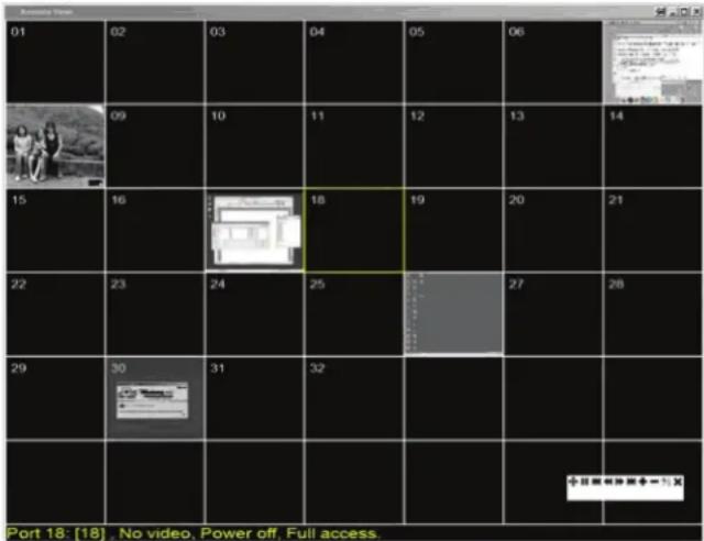
text_image
01 02 03 04 05 06 14 09 10 11 12 13 15 16 18 19 20 21 22 23 24 25 27 28 29 30 31 32 + + + + + + + + + + + + + + + + + + + + + + + + + + + + + + + + + + + + + + + + + + + + + + + + + + + + + + + + + + + + + + + + + + + + + + + + + + + + - 1. X Port 18: [18], No video, Power off, Full access.- Each panel represents one B064-Series KVM Switch's ports, beginning with Port 1 at the upper left and continuing from left to right and top to bottom.
- When the Array is first invoked, it scans through each of the ports that were selected for Auto Scanning in the Port Select and Filter functions, and displays information about the port (port name, resolution, online status, port access status), at the bottom of the panel.
Note: The Panel Array scans at one-second intervals. The scan interval is not user definable.
- The number of panels in the array can be increased or decreased by clicking the Show More Ports or Show Fewer Ports icons on the panel array toolbar.
- If the computer connected to a port is on line, its screen displays in the panel. If not, the panel remains blank.
- Only ports that are accessible to the currently logged in user are displayed. For ports that are not accessible, the panel is blank.
- If you move the mouse pointer over a panel, information about the port displays at the bottom of the panel.
- You can access a computer/server connected to a port by moving the mouse pointer over its panel and double-clicking. This will switch you to the computer exactly as if you had selected it from the OSD Main screen.
Panel Array Toolbar
The Panel Array Toolbar provides shortcut navigation and control of the panel array. The icons in the Panel Array Toolbar are described below:
| Icon Description | |
 | Click this icon to keep the Panel Array Toolbar visible at all times. Click it again to make the toolbar disappear after a few seconds. |
 | Click and drag any part of the toolbar that is not an icon to move the toolbar to another position on the screen. |
| [DH4Z] | Pause panel scanning, leaving the focus on the currently selected panel. |
| [C60Z] | Click to move the focus of the Panel Array scan back four panels. |
 | Click to move the focus of the Panel Array scan to the previous panel. |
| [BXYA] | Click to move the focus of the Panel Array scan to the next panel. |
| [84SS] | Click to move the focus of the Panel Array scan ahead four panels. |
 | Increase the number of panels in the array. |
| [ETTX] | Decrease the number of panels in the array. |
 | Toggle 4/3 aspect ratio. |
| [33ZA] | Exit Panel Array mode. |
Remote Session Operation (continued)
Multiuser Operation
B064-Series KVM Switches are designed to allow multiple users to access connected computers/servers simultaneously.
- The B064-032-02-IPG and B064-016-02-IPG are designed with 3 buses, which support 1 local user and 2 simultaneous remote users. When multiple users are logging on at the same time, the 1st, 3rd, 5th, etc. users to log in are all on the first bus. The 2nd, 4th, 6th, etc. users to log in are all on the second bus. The rules for multi-user operation in the table that follows this section apply to all users who are on the same bus.
- The B064-032-04-IPG and B064-016-04-IPG are designed with 5 buses, which support 1 local user and 4 simultaneous remote users. When multiple users are logged on at the same time, the 1st, 5th, 9th, etc. users are all on the first bus. The 2nd, 6th, 10th, etc. users are all on the second bus. The 3rd, 7th, 11th, etc. users are all on the third bus. The 4th, 8th, 12th, etc. users are all on the fourth bus. The rules for multi-user operation in the table that follows this section apply to all users who are on the same bus.
Operation Rules for Multi-Users on the Same Bus
| Auto Scan Mode | When Auto Scan mode is started, all users on that bus will go into Auto Scan mode. If a user on the same bus is in the OSD, they will not go into Auto Scan mode until they access one of the ports.Auto Scan mode can be stopped by any user by opening the OSD. When this occurs, all other users on the bus are switched to the port that last held the KVM's focus during Auto Scan mode. |
| Panel Array Mode | When Panel Array mode is invoked, all users on that bus will go into Panel Array mode. If a user on the same bus is in the OSD, they will not go into Panel Array mode until they access one of the ports. Panel Array mode can only be overridden by Super Administrators and Administrators.Only the user who starts Panel Array mode can use the skip icons in the Panel Array ToolbarOnly the user who starts Panel Array mode can switch ports. When switching to another port, all users on the bus are switched to the same port. If a user does not have access to the port, they will be unable to view it.Individual users can increase/decrease the number of panels they can see in Panel Array mode; however, the picture quality may get worse as the number of panels is decreased. For this reason, it is recommended that the user who starts Panel Array mode set it to display at least four panels. |
Auto Scanning
The Auto Scan function automatically switches among all accessible ports at regular intervals, so that the user can monitor their activity without having to manually switch between ports. The ports that are accessed in Auto Scan mode can be further filtered via the Filter section of the Port Access page. (See Filter section under Connections in OSD Operation for details.)
Setting the Scan Interval
The scan interval used during Auto Scan mode can be set in the User Settings menu. (See User Preferences section under OSD Operation for details.) The scan interval can be set from 1 to 255 seconds. The default is 5 seconds.
Invoking Auto Scan
Auto Scan Mode can be invoked when in the OSD or when in a remote session. When in the OSD, Auto Scan mode can be invoked by clicking on the Auto Scan button in the lower-left corner of the Port Access section. When in a remote session, Auto Scan Mode can be invoked by opening the OSD toolbar and tapping the A key. Once started, Auto Scan cycles through the ports in order, starting with the first accessible port on the installation. During Auto Scan Mode, an S appears in front of the Port ID Display to indicate that the port is being accessed under Auto Scan Mode.
Pausing Auto Scan
Auto Scan Mode can be paused in order to keep the focus on a particular computer by pressing P during an Auto Scan. When paused, the S that displays in front of the Port ID blinks On and Off. Pausing when you want to keep the focus on a particular computer can be more convenient than exiting Auto Scan Mode because when you resume scanning, you start from where you left off. If you were to exit and then restart Auto Scan Mode, the scanning would start over from the very first computer on the installation. To resume Auto Scan Mode after pausing, press any key except [Esc] or the [Spacebar], which will exit Auto Scan Mode completely.
Exiting Auto Scan
While Auto Scan Mode is in effect, ordinary keyboard functions are suspended. You must exit Auto Scan Mode in order to regain normal control of the keyboard. To exit Auto Scan Mode press [Esc] or the [Spacebar].
The Log Server
The Windows-based Log Server is an administrative utility that records all the events that take place on selected B064-Series KVM Switch units and writes them to a searchable database. This chapter describes how to install and configure the Log Server.
Installation
- From the computer that you want to use as the Log Server, open your browser and log into the B064-Series KVM Switch.
- Download the Log Server by clicking on the Download Icon at the top of the page and selecting it from the drop-down list.
- Navigate to where you saved the Log Server file and double-click on it to open it. If any security warning dialog boxes appear, ignore them and click Run or Open. The Log Server installation screen appears:
text_image
Welcome to the NetDirector Cat5 IP KVM Switch LogServer Setup This program will install the LogServer on your computer. We strongly recommend that you exit all Windows programs before running this program. Next Cancel- Click Next. Then follow the on-screen instructions to complete the installation and have the Log Server program icon placed on your desktop.
- Before starting up the Log Server, go to the Device Management section of the B064-Series KVM Switch OSD and open up the ANMS tab. In the corresponding fields, enter the MAC Address and Port Number for the computer/server that you have installed the Log Server on. (See Advanced Network Management Settings section under Device Management in OSD Operation for details)
Starting Up
To bring up the Log Server, either double click the program icon, or key in the full path to the program on the command line. The first time your run it, a screen similar to the one below appears:
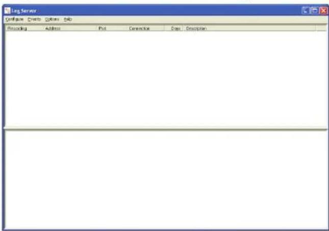
text_image
Leg Server Configure Events Settings Help Recording Address Plot Connection Data DescriptionNote: The Log Server requires the Microsoft Jet OLEDB 4.0 driver in order to access the database.
The screen is divided into three components:
• A Menu Bar at the top
- A panel that will contain a list of all B064-Series KVM Switch units in the middle
• A panel that will contain an Events List at the bottom
The Menu Bar
The Menu bar consists of four drop-down menus:
- Configure
- Events
- Options
- Help
Note: If the Menu Bar appears to be disabled, select one of the B064-Series KVM Switch units from the list window to enable it.
The Log Server (continued)
Configure
The Configure menu consists of three functions: Add, Edit and Delete.
Add
Select the Add function when you need to add a new B064-Series KVM Switch to the list of units that the Log Server records events for.
Note: You must first add a B064-Series KVM Switch via the Add function before the Log Server can start recording its events.
When you open the Add function the following dialog box will appear:
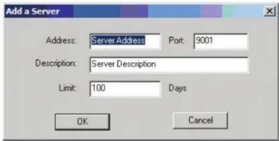
text_image
Add a Server Address: Server Address Port: 9001 Description: Server Description Limit: 100 Days OK CancelDescriptions of the fields in this dialog box are shown in the table below:
| Field Description | |
| Address | This can either be the IP address of the B064-Series KVM Switch or its DNS name (if the network administrator has assigned it a DNS name). This value must be entered into the ANMS tab of the OSD Device Management Notebook to communicate with the Log Server. (See Advanced Network Management Settings section for details.) |
| Port | Key in the port number that was specified in the ANMS tab of the OSD Device Management Notebook. If the port number differs between the B064-Series KVM Switch OSD and the Log Server, the two will not be able to communicate with each other. |
| Description | This field is provided so that you can enter in additional information that will help differentiate this B064-Series KVM Switch from the rest of the devices the Log Server is recording information for. |
| Limit | This specifies the number of days that an event is kept in the Log Server's database before it can be deleted. To remove all events that have passed the expiration date set in this field, use the Maintenance function in the Events menu. |
Edit
Select the Edit function to modify the information pertaining to an existing B064-Series KVM Switch. To edit an existing B064-Series KVM Switch, select it from the list and open the Edit function from the Configure drop-down menu. A dialog box will appear showing the exact information that was entered for the B064-Series KVM Switch when it was added using the Add function. Edit this information and click OK.
Delete
To delete a B064-Series KVM Switch, simply select it from the list and open the Delete function. A dialog box will appear which will display the B064-Series KVM Switch information and ask you to click OK to delete it. If you want to remove it from the Log Server, click OK.
The Log Server (continued)
Events
The Events Menu consists of two items: Search and Maintenance.
Search
Search allows you to search for events containing specific words or strings. When you access this function, a screen similar to the one below appears:
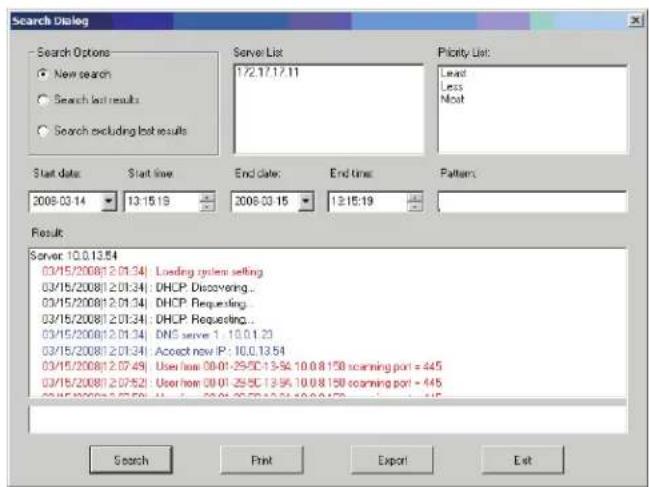
text_image
Search Dialog Search Options New search Search lost results Search excluding lost results Server List 1/2.17.17.11 Priority List: Lead Less Most Start date: 2008-03-14 Start time 13:15:19 End date: 2008-03-15 End time 13:15:19 Pattern: Result Server 10.0.13.54 03/15/2008/1 2.01.34: Loading system setting 03/15/2008/1 2.01.34: DHCP Discovering... 03/15/2008/1 2.01.34: DHCP Requesting... 03/15/2008/1 2.01.34: DHCP Requesting... 03/15/2008/1 2.01.34: DNS server 1: 10.0.1.23 03/15/2008/1 2.01.34: Accept now IP : 10.0.13.54 03/15/2008/1 2.07.49: User how 00:01-25-SC 13:56:10.0.8.15B scanning port = 445 03/15/2008/1 2.07.52: User how 00:01-25-SC 13:56:10.0.8.15B scanning port = 445 03/15/2008/1 2.07.53: User how 00:01-25-SC 13:56:10.0.8.15B scanning port = 445 Search Print Export ExitA description of the items from the Search screen is given in the table below:
| Item Description | |
| Search Options | New search: When selected, the search is performed on all the events in the database for the selected B064-Series KVM Switch.Search last results: This is a secondary search performed on the events that resulted from the last search.Search excluding last results: This is a secondary search performed on all the events in the database for the selected B064-Series KVM Switch excluding the events that resulted from the last search. |
| Server List | B064-Series KVM Switch units are listed according to their IP address. Select the unit that you want to perform the search on from this list. You can select more than one unit for the search. If no units are selected, the search is performed on all of them. |
| Priority List | Sets the level for how detailed the search results display should be. If nothing is selected, all results will display. If all results do display, entries highlighted in Red are of high or Most important to installations security. Entries highlighted in Blue are of medium or Less important to installations security. Entries highlighted in Black are of the least or Least important to installations security. |
| Start Date Select the date | that you want the search to start from. The format follows the MM/DD/YYYY convention. (e.g. 11/15/2009) |
| Start Time Select the time | that you want the search to start from. |
| End Date | Select the date that you want the search to end at. The format follows the MM/DD/YYYY convention. (e.g. 11/15/2009) |
| End Time Select the time | that you want the search to end at. |
| Pattern Key in text here that you want the search to filter the events by. | |
| Results The events that matched your search terms are listed here. | |
| Search After you have entered in all of your search terms, click this button to start the search. | |
| Print Click this button to print the search results. | |
| Export Click this button to export Log Server search results as a text file | |
| Exit | Click this button to exit the Search dialog box. |
Maintenance
This function allows the administrator to remove all records that have passed their expiration limit. (See Configure under The Log Server for limit details) In order to delete old files from the log server, the maintenance function must be performed.
The Log Server (continued)
Options
The Options menu consists of only one function: Network Retry.
Network Retry
Network Retry allows you to set the number of seconds that the Log Server should wait before attempting to connect if the previous connection attempt failed. When you click this item, a dialog box, similar to the one below appears:
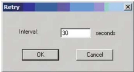
text_image
Retry Interval: 30 seconds OK CancelKey in the desired number of seconds and click OK to finish.
Help
The Help menu consists of two options; Contents and About Log Server.
Contents
Selecting the Contents function brings up an online Windows Help file. The Help file contains instructions on how to set up, operate and troubleshoot the Log Server.
About Log Server
Selecting the About Log Server option brings up a dialog box that displays the version number of the Log Server.
The Log Server Main Screen — Overview
The Log Server Main Screen is divided into two main panels: an upper (List) panel that displays all devices that have been added to the Log Server and a lower (Event) panel that displays the log events for the currently selected B064-Series KVM Switch. To select a B064-Series KVM Switch unit in the list, simply click on it.
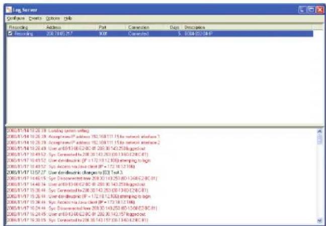
text_image
Log Server Configure Devices Options Help Recording Address Part Conversion Data Descriptions 208.714 10.26.19 Loading system setting 208.714 10.26.19 Accept newIP address 192.169/11.15 to network interface 1 208.714 10.26.19 Accept newIP address 192.169/11.15 to network interface 2 208.714 10.26.43 Use at 693.30/62.80 (P = 208.36/42.25/86/84) 208.714 10.49.52 Sys Connected to 208.30/42.263 (30/1340/28C/81) 208.714 10.49.52 Use diskable (IF = 172.19/12.80) attempting to begin 208.714 10.49.52 Sys Access via Java client (P = 172.19/12.86) 208.714 13.57.27 Use diskable changes to [D] Test 3 208.714 14.46.15 Sys Connected to 208.30/43.25/80/1340/28C/81 208.714 14.46.34 Use at 693.30/62.80 (P = 208.36/43.25/86/84) 208.714 15.36.44 Sys Connected to 208.30/43.25/80/1340/28C/81 208.714 15.36.44 Use diskable (IF = 172.19/12.80) attempting to begin 208.714 15.36.44 Sys Access via Java client (P = 172.19/12.86) 208.714 16.34.44 Sys Connected to 208.30/43.25/80/1340/28C/81 208.714 16.34.45 Use at 693.30/62.80 (P = 208.36/43.25/86/84) 208.714 16.34.45 Sys Connected to 208.30/43.25/80/1340/28C/81The Log Server (continued)
The Log Server Main Screen — Overview (continued)
The List Panel
The List panel contains the following fields:
| Field Description | |
| Recording | Determines whether the Log Server records log events for the corresponding B064-Series KVM Switch. If the Recording check box is checked, the field displays Recording, and log events are recorded. If the Recording check box is not checked, the field displays Paused, and log events are not recorded.Note: Even if a B064-Series KVM Switch is not currently selected, if its Recording check box is checked, the Log Server will still record its log events. |
| Address This is the IP Address or DNS name that was given to the B064-Series KVM Switch when it was added to the Log Server. | |
| Port | This is the port number that was assigned to the B064-Series KVM Switch when it was added to the Log Server. |
| Connection | If the Log Server is properly connected to the B064-Series KVM Switch, this field displays Connected. If it is not connected, this field displays Waiting. This means that the Log Server is not communicating with the B064-Series KVM Switch, and will not record its events. This occurs when the Log Server's MAC address and/or port number have not been set properly. The MAC Address and Port for the Log Server computer must be entered into the ANMS tab of the OSD Device Management Section. In addition, the B064-Series KVM Switch's IP Address and Port must be entered when adding it to the Log Server. If the Port numbers in the B064-Series KVM Switch and the Log Server do not match, they will not be able to communicate. |
| Days | This field displays the number of days that the B064-Series KVM Switch's log events are to be kept in the Log Server's database before it is eligible for deletion. |
| Description | This field displays the descriptive information given for the B064-Series KVM Switch when it was added to the Log Server. |
The Event Panel
The lower panel displays event information for the currently selected B064-Series KVM Switch.
Appendix
Keyboard Emulation
Mac Keyboard
The PC compatible (101/104 key) keyboard can emulate the functions of the Mac keyboard. The emulation mappings are listed in the table below.
| PC Keyboard Mac Keyboard | |
| [Shift] Shift | |
| [Ctrl] Ctrl | |
| H | |
| [Ctrl] [1] | |
| [Ctrl] [2] | |
| [Ctrl] [3] | |
| [Ctrl] [4] | |
| [Alt] Alt | |
| [Print Screen] F13 | |
| [Scroll Lock] F14 | |
| = | |
| [Enter] Return | |
| [Backspace] Delete | |
| [Insert] Help | |
| [Ctrl] | F15 |
Note: When using key combinations, press and release the first key (Ctrl), then press and release the activation key.
Sun Keyboard
The PC compatible (101/104 key) keyboard can emulate the functions of the Sun keyboard when the Control key [Ctrl] is used in conjunction with other keys. The corresponding functions are shown in the table below.
| PC Keyboard Sun Keyboard | |
| [Ctrl] [T] | Stop |
| [Ctrl] [F2] | Again |
| [Ctrl] [F3] | Props |
| [Ctrl] [F4] | Undo |
| [Ctrl] [F5] | Front |
| [Ctrl] [F6] | Copy |
| [Ctrl] [F7] | Open |
| [Ctrl] [F8] | Paste |
| [Ctrl] [F9] | Find |
| [Ctrl] [F10] | Cut |
| [Ctrl] [1] | |
| [Ctrl] [2] | |
| [Ctrl] [3] | |
| [Ctrl] [4] | |
| [Ctrl] [H] | Help |
| Compose | |
Note: When using key combinations, press and release the first key (Ctrl), then press and release the activation key.
Appendix (continued)
General Operation Troubleshooting
| Problem Action | |
| Erratic Operation. If a KVM switch is cascaded from it, the upper-level KVM must always be powered on before the lower-level KVM. If the cascaded switch was turned on first, resetting it may resolve the issue. If not, power off the installation and power everything on according to the installation instructions in this manual. Reset the unit by pressing and holding the Reset button on the front of the unit for longer than three seconds. | |
| I can't access the B064-Series KVM Switch, even though I have specified the IP address and port number correctly. | If the B064-Series KVM Switch is behind a router, the router's Port Forwarding (also referred to as Virtual Server) feature must be configured. |
| Mouse and/or Keyboard not responding. | If accessing the KVM via local console, unplug and replug the cable(s) from the console port(s).Turn the connected computer/server off and then back on. All connected devices need to be powered off when connecting to the KVM. |
| Sudden loss of network connection. | Close your B064-Series KVM Switch connection. Wait approximately 30 seconds, and log in again. |
| No video display on the remote console. | Make sure the resolution of the monitor being used to display the remote computer/server is higher than that of the remote computer/server.Make sure the OSD toolbar is closed. Sometimes mouse movement is required to bring the screen out of sleep mode. If the OSD toolbar is open, your mouse input is not being received by the remote computer/server.Check the firmware version number of the Server Interface Unit (SIU) you have connected to make sure it is the most current. (See Upgrade Main Firmware section under Maintenance in OSD Operation for details.) If not, upgrade the SIUs firmware.Press and release the left [Alt] key, then press and release the right [Alt] key. |
| When logging in from a browser, the following message appears: 404 Object Not Found. | If a login string has been set (see Login String section under Device Management in OSD Operation for details), make sure to include the forward slash and correct login string when you specify the B064-Series KVM Switch IP address. |
| When I log in, the browser generates a CA Root certificate is not trusted, or a Certificate Error response. | The certificate can be trusted; you can proceed. |
| There are two mouse pointers after the remote system is accessed. | The KVM automatically defaults to show both the local and remote mouse pointers. You can choose to display both mouse pointers at the same time or only the remote mouse pointer. (See Mouse Pointer section under OSD Main Page in OSD Operation for details.) |
| The display on the remote console is distorted and performing an Autosync doesn't resolve the problem. | Switch ports to a port with a different resolution and then switch back.Lower the resolution and refresh rate for the computer/server connected to the port. |
| I have been given an account, but I am unable to login | Make sure that you have correctly entered your username and password.Make sure that your System Administrator has given you proper access to the KVM switch. |
| The Lock LEDs on the Control Panel do not accurately portray my Lock status | Click the LEDs on the Control Panel until they match those on your keyboard. Once matched up, changing a Lock LED on the keyboard will also change it in the Control Panel and vice versa. |
| When I open a viewer, the web page does not display properly, and I receive an error message that says "Problems with this Web page might prevent it from being displayed properly..." | By default, IE6 and some versions of IE5 use the High security level for the Restricted Sites zone. Windows Server 2003 uses High security for both the Restricted Sites and Internet zones. You may need to enable Active Scripting, ActiveX Controls and Java Applets. To do this, follow these steps: 1) In Internet Explorer, open the Tools menu and select Internet Options. 2) In the Internet Options dialog box, click Security. 3) Click Default level, and click OK when prompted.Verify that Active Scripting, ActiveX Controls and Java Applets are not blocked. If some client computers work and others don't, verify the Internet Explorer or another program (e.g. Anti-Virus, Firewall, etc.) on your client computer are not configured to block Scripts, ActiveX Controls or Java Applets.Verify that your anti-virus program is not set to scan the Temporary Internet Files or Downloaded Program Files folders.Delete all temporary internet related files by following these steps: 1) Open the Tools menu in Internet Explorer and select Internet Options 2) Click on the General tab 3) Under Temporary Internet Files, click Settings 4) Click Delete Files and click OK when prompted 5) Click Delete Cookies and click OK when prompted 6) Under History, click on Clear History, Yes and click OK when prompted.Make sure that you have the latest version of Microsoft DirectX installed.Make sure that you have the latest version of Java installed. |
Administration Troubleshooting
| Problem Action | |
| After upgrading the firmware and logging back in, the B064-Series KVM Switch appears to still be using the old firmware version. | Clear your browser's cache. Delete all temporary internet files and cookies. Close the browser and reopen it to log in with a new session. |
Appendix (continued)
Mouse Troubleshooting
| Problem Action | |
| My mouse and/or keyboard is not responding. | Check the firmware version number of the Server Interface Unit (SIU) you have connected to make sure it is the most current. (See Upgrade Main Firmware section under Maintenance in OSD Operation for details.) If not, upgrade the SIUs firmware.Turn off the computer/server you are having trouble with. Unplug and re-plug the SIU from the computer/server. Turn the computer/server back on. |
| Mouse movement is extremely slow. There is too much data going through your connection.If the remote computer's wallpaper has a lot of graphics, switch it to a plain wallpaper.Adjust your video settings to reduce the amount of data per the instructions in the Video Settings section under OSD Main Page. | |
| There are two mouse pointers on my screen, how do I change this? | You can choose between 3 different pointer types. See Mouse Pointer section under OSD Main Page. |
| My mouse pointers don't sync. | See Mouse Pointer section under OSD Main Page. |
Virtual Media Troubleshooting
| Problem Action | |
| Virtual Media works on all of my computers except one. | The remote server's mainboard may not support USB. Check to see if there is a new firmware and BIOS version for the mainboard that does support USB. |
| There is no Virtual Media icon on my control panel. | • Virtual Media is only accessible on computers/servers that are connected to the KVM switch using a B055-001-USB-V2• Make sure that your System Administrator has given you access to the Virtual Media functionality. |
| I can't boot my remote server from my Virtual Media drive. | Your remote server's BIOS may not support booting from a USB drive. Check to see if there is a new firmware and BIOS version for the mainboard that does support USB. |
| If I connect a USB floppy drive to a remote server, it can boot the remote server; however, if I map it to the remote server as a Virtual Media drive, it cannot boot the remote server. | USB floppy drives have two types of format: UFI and CBI. Both can be used for OS level Virtual Media functions, but only UFI is currently supported for BIOS level, which includes boot functions. |
| I cannot mount a Folder as a Virtual Media device. | If the folder is formatted with the FAT16 file system, it must be less than 2Gb to be mounted. |
AP Windows Client Troubleshooting
| Problem Action | |
| Windows Client won't connect to the B064-Series KVM Switch. | DirectX 8.0 or higher must be installed on your computer. |
| Remote mouse pointer is out of sync. | Perform a Video Auto Sync. (See Video Settings section under OSD Main Page in OSD Operation for details.) This will usually sync the local and remote mouse pointers.Use the Adjust Mouse Hotkey command. (See Hotkeys section under OSD Main Page in OSD Operation for details.)If this does not work, see Mouse Pointer section under OSD Main Page. |
| Part of remote window is off my monitor. | If Keep Screen Size is not enabled (see Screen Mode section under OSD Main Page in OSD Operation for details), try performing a Video Auto Sync (see Video Settings section under OSD Main Page in OSD Operation) to sync the local and remote monitors. If this does not work, you may have to manually adjust the Screen Position in the Video Settings screen.If Keep Screen Size is enabled, areas that are off the screen can be accessed by positioning the mouse pointer on the far side of the area you want to scroll to. |
| The remote screen is rotated 90 degrees. | Enable Keep Screen Size. (See Control Panel section under OSD Main Page in OSD Operation.) |
| I cannot run Net Meeting when the Windows Client is running. | Enable Keep Screen Size. (See Control Panel section under OSD Main Page in OSD Operation.) |
| My B064-Series KVM switch is not showing up in the device list when I open the AP Windows Client. | The port number entered into the Program field of your KVMs Network page (see IP Installer section under NIC Settings in Super Administrator Setup for details) must match the port number entered into the AP Windows Client's Port field. Only KVMs that match the port number entered into this field will show up in the device list.The Enable Device List option must be checked on the Operating Mode page for your KVM switch to show up in the Device List. (See Working Mode section under Device Management in OSD Operation for details.) |
| After upgrading the firmware to my KVM switch, the AP Windows Client no longer works. | The old version of you .ocx file was not deleted. Open Explorer and search for WinClient.ocx. Delete all occurrences. |
Appendix (continued)
WinClient ActiveX Viewer Troubleshooting
| Problem Action | |
| The WinClient ActiveX Viewer will not connect to the KVM switch. | DirectX 8.0 or higher must be installed on your client computer. |
| After upgrading the firmware to my KVM switch, the WinClient ActiveX Viewer no longer works. | The old version of your .ocx file was not deleted. Open Internet Explorer > Tools > Manage Add-ons. Delete or disable all occurrences of WinClient. |
| Part of the remote window is off my monitor. | ·If Keep Screen Size is not enabled (see Control Panel section under Remote Session Operation), try performing a Video Auto Sync (see Video Settings section). If this does not work, you may have to manually adjust the video via the Video Settings page.·If Keep Screen Size is enabled, areas that are off the screen can be accessed by positioning the mouse pointer on the far side of the area you want to scroll to. |
| The remote screen is rotated 90 degrees. | Enable the Keep Screen Size function. (See Control Panel section under Remote Session Operation for details.) |
| I cannot run Net Meeting when the WinClient is running. | Enable the Keep Screen Size function. (See Control Panel section under Remote Session Operation for details.) |
| After logging in, I can’t open the WinClient ActiveX viewer. | ·You don’t have the authority to install the WinClient Control Add-on on your client computer. Have your system administrator run the program for you the first time.·Under Vista, you must also add the KVM switches URL to the list of trusted sites. Go to Tools > Internet Options > Security > Trusted Sites > Sites |
| When using Vista, I open the WinClient ActiveX Viewer and try to mount a driver or removable disk, but I am getting a message that says “Driver not ready.” | This is due to Vista’s User Account Control (UAC). If you are the computer’s administrator, open your browser by right-clicking on it and selecting Run as Administrator. If you are not the administrator, you will need to have the administrator disable UAC. |
Panel Array Mode Troubleshooting
| Problem Action | |
| The video resolution is of low quality. | This occasionally occurs when the screens are scaled down to fit into each panel. Decrease the number of panels that are displayed. |
| When multiple remote users are logged in, some of them only receive a partial image. | The first user to invoke Panel Array Mode should set it to display at least four panels. |
Java Applet & AP Java Client Troubleshooting
For mouse synchronization problems, see Manual Mouse Synchronization section under Control Panel in Remote Session Operation. For connection and operation problems, see the table below:
| Problem Action | |
| The AP Java Client won't connect to the B064-Series KVM Switch. | Java Runtime Environment 6, Update 3 or higher must be installed on your computer.If a login string has been set, make sure to include the forward slash and correct string (see Login String section under Device Management in OSD Operation for details) when you specify the B064-Series KVM Switch's IP address.Try closing the Java client and opening it again. |
| Pressing the Windows Menu key has no effect. | Java doesn't support the Windows Menu key. |
| Java Client performance deteriorates. Exi | the program and start again. |
| National language characters do not appear. | You must set the appropriate keyboard language in the Port Properties tab of the Port Access page.(See Port Properties section under Connections in OSD Operation for details.) |
| After upgrading the firmware of my KVM switch and logging into the OSD, my switch is still showing the old firmware version number. | You need to delete your Java temporary internet files. Open Control Panel > Java, and click on the Settings button in the Temporary Internet Files section. In the Disk Space section, click on Delete Files. When prompted, click OK. |
| When I try to add a folder to be mounted as a Virtual Media Drive, I am unable to select the folder. The only option I have is desktop. | In the folder selection entry field, enter the root directory of the folder you want to add. After that, the folders contained under the root directory will be displayed. |
Appendix (continued)
Log Server Troubleshooting
Problem Action
| The Log Server program does not run. | The Log Server requires the Microsoft Jet OLEDB 4.0 driver in order to access the database. This driver is automatically installed with Windows ME, 2000 and XP. For Windows 98 or NT, you will have to go to the Microsoft download site:http://www.microsoft.com/data/download.htm to retrieve the driver file: MDAC 2.7 RTM Refresh (2.70.9001.0).Since this driver is used in Windows Office Suite, an alternate method of obtaining it is to install Windows Office Suite. Once the driver file or Suite has been installed, the Log Server will run. |
Sun Systems Troubleshooting
Problem Action
| Video display problems with HD15 interface systems (e.g. Sun Blade 1000 servers).* | The display resolution should be set to 1024 x 768 @ 60Hz:Under Text Mode go to OK mode and issue the following commands:setenv output-device screen:r1024x768x60 reset-allUnder XWindow:Open a console and issue the following command: m64config -res 1024x768x60Log outLog in |
| Video display problems with 13W3 interface systems.(e.g. Sun Ultra servers)* | The display resolution should be set to 1024 x 768 @ 60Hz:Under Text Mode go to OK mode and issue the following commands:setenv output-device screen:r1024x768x60 reset-allUnder XWindow:Open a console and issue the following command: ffbconfig -res 1024x768x60Log outLog in |
| The local and remote mouse pointers do not sync. | See Manual Mouse Synchronization section. |
* These solutions work for most common Sun VGA cards. If using them fails to resolve the problem, consult the Sun VGA card's manual.
Specifications
| B064-008-01-IPG | B064-016-01-IPG | B064-016-02-IPG | B064-016-04-IPG | B064-032-01-IPG | B064-032-02-IPG | B064-032-04-IPG | B064-064-08-IPG | |
| Port Selection Methods Pushbutton | OSD and Hotkey | |||||||
| Local Console Ports HD18 Connector | on back panel connects to included USB/PS2 Combo Console Cable Kit | |||||||
| Computer/Server Ports | (x8) RJ45 F | (x16) RJ45 F | (x32) RJ45 F | (64) RJ45 F | ||||
| LAN Ports | (x2) RJ45 F | |||||||
| Dial-In Modem Port | RJ45 F | |||||||
| Multi-User Capability | 1 Local, 1 Remote | 1 Local, 1 Remote | 1 Local, 2 Remote | 1 Local, 4 Remote | 1 Local, 1 Remote | 1 Local, 2 Remote | 1 Local, 4 Remote | 1 Local, 8 Remote |
| Dual-Power Supplies | Yes | |||||||
| Power Input Connector | (x2) IEC-320-C6 | |||||||
| I/P Rating | 100-240V, 50/60Hz, 1A | |||||||
| Single Power Supply Consumption | 120V (15.8W)230V (14.7W) | 120V (18.0W)230V (16.7W) | 120V (36W)230V (33.8W) | 120V (42.78W)230V (41.5W) | 120V (27.9W)230V (27.7W) | 120V (44.87W)230V (43.7W) | 120V (48W)230V (46.6W) | 120V (85.9W)230V (80.5W) |
| Dual Power Supply Consumption | 120V (16.9W)230V (17.1W) | 120V (18.5W)230V (18.1W) | 120V (39.65W)230V (38.7W) | 120V (43.2W)230V (40W) | 120V (28.5W)230V (29.1W) | 120V (46.04W)230V (43W) | 120V (49.96W)230V (46.3W) | 120V (91.1W)230V (85.7W) |
| On/Off Power Switch | Yes | |||||||
| Additional USB Ports | (x3) USB A F | |||||||
| Reset Button | Yes | |||||||
| Port Selection Pushbuttons | 2 | |||||||
| Keyboard/Mouse Emulation | USB (PC, Mac, Sun), PS/2, Serial | |||||||
| Max Video Resolution | 1600 x 1200 @ 60Hz | |||||||
| Operating Temperature | 32°F to 122°F (0°C to 50°C) | |||||||
| Storage Temperature | -4°F to 140°F (-20°C to 60°C) | |||||||
| Humidity | 0 to 80%, RH, Noncondensing | |||||||
| Dimensions (H x W x D) | 1.75 x 17 x 10.75 in. / 4 x 43 x 27 cm | 1.75 x 17 x 10.75 in. / 4 x 43 x 27 cm | ||||||
Factory Default Settings
| Setting Default | |
| Language English | |
| OSD Hotkey [Scroll Lock], [Scroll Lock] | |
| Port ID Display Port Number + Name | |
| Port ID Display Duration 3 Seconds | |
| Scan/Skip Mode All | |
| Scan Duration 5 Seconds | |
| Screen Blanker 0 minutes (Disabled) | |
| Beeper On | |
| Viewer Auto Detect | |
| Welcome Message Hide | |
| Accessible Ports Super Administrators – Full Access for all portsAdministrators and Users – No Access for all ports | |
Specifications (continued)
Serial Adapter Pin Assignments
The table below shows the pin assignments for the RJ45 to DB9 Adapter (DTE to DCE) that comes with the unit.
| Switch (RJ45) Pins Modem (DB9) | ||
| RTS 1 7 | ||
| DTR 2 4 | ||
| TXD 3 3 | ||
| CTS 4 8 | ||
| GND 5 5 | ||
| RXD 6 2 | ||
| DCD 7 1 | ||
| DSR 8 6 | ||
| 9 NC Not Used | ||
Fan Location & Speed Information
The B064-Series KVM switch contains 6 fans, whose location is shown in the image below.
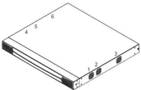
text_image
Diagram of a rectangular electronic device with numbered components, likely an optical or memory module.Fan Speed
Fan speed is automatically adjusted according to temperature. When the temperature reaches the levels mentioned below, the KVM switches temperature sensors adjust the fan speed accordingly.
- If any of the four sensors sense a temperature greater than 89^ (32^) , all of the fans will be set to spin at half speed
- When all four sensors sense the temperature is below 86°F (30°C), all of the fans will be turned off
- If any of the four sensors sense a temperature greater than 113°F (45°C), all of the fans will be set to spin at full speed
- When all four sensors sense the temperature is below 104^ (40^) , all of the fans will be set to spin at half speed
Temperature Sensor Location
The location of the KVM switches for temperature sensors is shown in the image below.
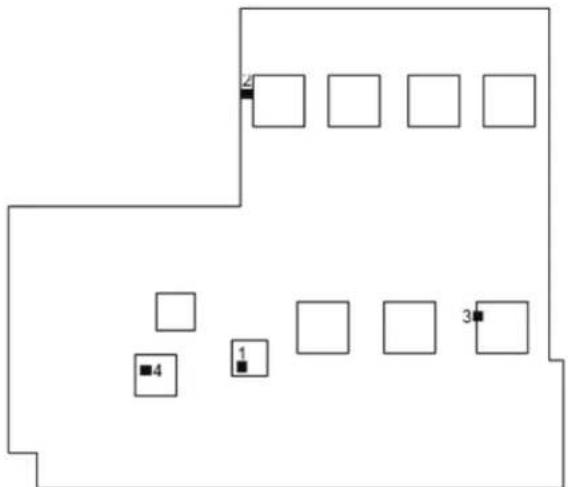
flowchart
graph TD
    A[" "] --> B[" "]
    C[" "] --> D[" "]
    E[" "] --> F[" "]
    G[" "] --> H[" "]
    I[" "] --> J[" "]
    K[" "] --> L[" "]
    M[" "] --> N[" "]
    O[" "] --> P[" "]
    Q[" "] --> R[" "]
    S[" "] --> T[" "]
    U[" "] --> V[" "]
    W[" "] --> X[" "]
    Y[" "] --> Z[" "]
Note: The temperature inside the case can be higher than the ambient operating temperature of the KVM switch (32°F to 122°F / 0°C to 50°C). However, if the temperature reading shown in the Device Information section surpasses 185°F (85°C), you should either cool down the room or shut down the switch until it cools.
PRODUCT REGISTRATION
Visit www.triplite.com/warranty today to register your new Tripp Lite product. You'll be automatically entered into a drawing for a chance to win a FREE Tripp Lite product!*
* No purchase necessary. Void where prohibited. Some restrictions apply. See website for details.
3-Year Limited Warranty
TRIPP LITE warrants its products to be free from defects in materials and workmanship for a period of three (3) years from the date of initial purchase. TRIPP LITE's obligation under this warranty is limited to repairing or replacing (at its sole option) any such defective products. To obtain service under this warranty, you must obtain a Returned Material Authorization (RMA) number from TRIPP LITE or an authorized TRIPP LITE service center. Products must be returned to TRIPP LITE or an authorized TRIPP LITE service center with transportation charges prepaid and must be accompanied by a brief description of the problem encountered and proof of date and place of purchase. This warranty does not apply to equipment which has been damaged by accident, negligence or misapplication or has been altered or modified in any way.
EXCEPT AS PROVIDED HEREIN, TRIPP LITE MAKES NO WARRANTIES, EXPRESS OR IMPLIED, INCLUDING WARRANTIES OF MERCHANTABILITY AND FITNESS FOR A PARTICULAR PURPOSE. Some states do not permit limitation or exclusion of implied warranties; therefore, the aforesaid limitation(s) or exclusion(s) may not apply to the purchaser.
EXCEPT AS PROVIDED ABOVE, IN NO EVENT WILL TRIPP LITE BE LIABLE FOR DIRECT, INDIRECT, SPECIAL, INCIDENTAL OR CONSEQUENTIAL DAMAGES ARISING OUT OF THE USE OF THIS PRODUCT, EVEN IF ADVISED OF THE POSSIBILITY OF SUCH DAMAGE. Specifically, TRIPP LITE is not liable for any costs, such as lost profits or revenue, loss of equipment, loss of use of equipment, loss of software, loss of data, costs of substitutes, claims by third parties, or otherwise.
FCC Notice, Class A
This device complies with part 15 of the FCC Rules. Operation is subject to the following two conditions: (1) This device may not cause harmful interference, and (2) this device must accept any interference received, including interference that may cause undesired operation.
Note: This equipment has been tested and found to comply with the limits for a Class A digital device, pursuant to part 15 of the FCC Rules. These limits are designed to provide reasonable protection against harmful interference when the equipment is operated in a commercial environment. This equipment generates, uses, and can radiate radio frequency energy and, if not installed and used in accordance with the instruction manual, may cause harmful interference to radio communications. Operation of this equipment in a residential area is likely to cause harmful interference in which case the user will be required to correct the interference at his own expense. The user must use shielded cables and connectors with this equipment. Any changes or modifications to this equipment not expressly approved by Tripp Lite could void the user's authority to operate this equipment.
WEEE Compliance Information for Tripp Lite Customers and Recyclers (European Union)

Under the Waste Electrical and Electronic Equipment (WEEE) Directive and implementing regulations, when customers buy new electrical and electronic equipment from Tripp Lite they are entitled to:
- Send old equipment for recycling on a one-for-one, like-for-like basis (this varies depending on the country)
- Send the new equipment back for recycling when this ultimately becomes waste
Tripp Lite has a policy of continuous improvement. Product specifications are subject to change without notice.

text_image
TRIPP·LITE
1111 W. 35th Street, Chicago, IL 60609 USA • www.tripplite.com/support