QCN8002 - Security Camera Q-See - Free user manual and instructions
Find the device manual for free QCN8002 Q-See in PDF.

User questions about QCN8002 Q-See
0 question about this device. Answer the ones you know or ask your own.
Ask a new question about this device
Download the instructions for your Security Camera in PDF format for free! Find your manual QCN8002 - Q-See and take your electronic device back in hand. On this page are published all the documents necessary for the use of your device. QCN8002 by Q-See.
USER MANUAL QCN8002 Q-See
natural_image
White QG-SE security camera with visible lens and sensor array (no text or symbols)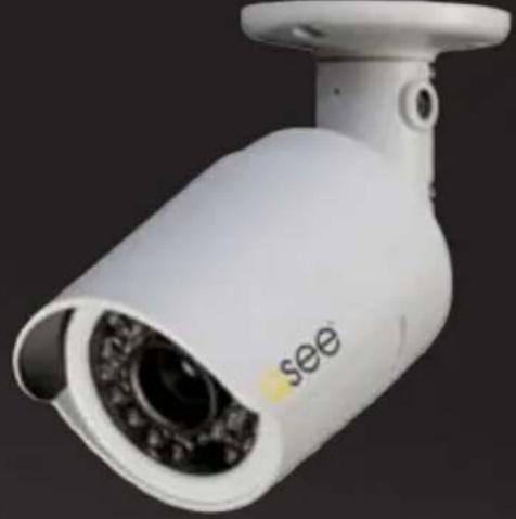
natural_image
White surveillance camera with 'see' label on lens (no other text or symbols visible)
text_image
QC SERIES
natural_image
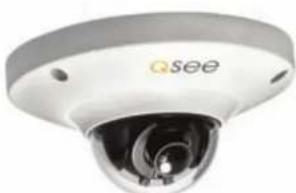
Close-up of a white spherical security camera with a lens and head, no visible text or symbols on the device itself.
Thank You for Choosing a Q-See Product!
All of our products are backed by a conditional service warranty covering all hardware for 12 months from the date of purchase. Additionally, our products also come with a free exchange policy that covers all manufacturing defects for one month from the date of purchase.
Permanent upgrading service is provided for the software and is available at www.Q-See.com.
Be certain to make the most of your warranty by completing the registration form online. In addition to warranty and technical support benefits, you'll receive notifications of product updates along with free downloadable firmware updates for your NVR. Register today at www.Q-See.com!
Please see the back of this manual for exclusions.

text_image
ONLINE PRODUCT REGISTRATION Register your product to receive important downloads and updates. www.q-see.com Qsee© 2011-2012 Q-See. Reproduction in whole or in part without written permission is prohibited. All rights reserved. This manual and software and hardware described herein, in whole or in part, may not be reproduced, translated, or reduced to any machine-readable form without prior written approval.
Trademarks: All brand names and products are trademarks or registered trademarks of their respective owners.
Q-See is a registered trademark of DPS, Inc.
Disclaimer: The information in this document is subject to change without notice. The manufacturer makes no representations or warranties, either express or implied, of any kind with respect to completeness of its contents.
Manufacturer shall not be liable for any damages whatsoever from misuse of this product.
About this Manual
This manual is written for the QCN7001B, QCN7002D, QCN8001B and QCN8002D IP Cameras and was accurate at the time it was completed. However, because of our ongoing effort to constantly improve our products, and the different capabilities of the three models additional features and functions may have been added since that time and on-screen displays may change. We encourage you to visit our website at www.Q-sec.com to check for the latest firmware updates and product announcements.
This manual covers the setup and local operation of the IP cameras whether used in conjunction with an NVR or as stand-alone devices. Instructions for use with an NVR is written specifically with Q-See's QC-Series NVRs. If you are using another brand, please consult your system's manual for configuration instructions. The QC-Series User Manual and Remote Monitoring Guide will both be useful in configuring your system. Both are included on the CD that accompanied your NVR and can likewise be found on www.Q-See.com/support.
Throughout the manual we have highlighted warnings and other important information that will assist you in operating your new system in a safe and trouble-free manner. Please take the time to read and follow all instructions and pay attention to alerts as shown below;

IMPORTANT! Red boxes with this icon indicate warnings. To prevent possible injury or damage to the product, read all warnings before use.

NOTE! Text in blue boxes with the Information icon offer additional guidance and explanations about how to make the most out of your system.
Version 1.0 8/8/12
TABLE OF CONTENTS
1. CAMERA SPECIFICATIONS 8
QCN7001B 8
QCN7002D 9
QCN8001B 10
Adjusting the lens 11
QCN8002D 14
2. CONNECTING IP CAMERAS 16
2.1 What are IP Cameras? 16
2.2 Connecting an IP Camera 17
Locally connecting to an NVR 17
Cameras connected through a network 18
2.2 Adding and Removing Cameras in Your System 20
Local cameras 20
Cameras on the same network 20
QC NVR Remote Device menu 21
2.3 Connecting Your Camera to a Remote Network 24
Before you get started 24
Obtaining IP Information using IPCONFIG in Windows 25
Testing the connection 27
Opened ports and Internet IP address 29
2.4 Troubleshooting Network Connections 30
Opening ports 30
Issues with DHCP 34
Multiple routers on the nNetwork 35
Configuring ActiveX 38
2.5 Additional Network Services 43
Entering the DNS information into the camera 45
2.6 Dynamic Domain Name Service (DDNS) 47
3. USING WEB SERVICE 48
3.1 Live View
Function Buttons (PC only) 49
3.2 Setup 50
Camera 50
Video 51
3.3 Network 52
TCP/IP 52
Static IP Address 52
PPPoE 53
DDNS 53
IP Filter 53
SMTP (E-Mail) 54
UPnP (Universal Plug 'n' Play) 54
Bonjour 54
3.4 Event 55
Motion Detection 55
Video Masking 56
Disconnection 56
IP Conflict 56
3.5 Record 57
Record shedule 57
Snapshot schedule 57
File destination path 58
Record control 58
3.6 System 59
General 59
Date & time 59
Account 60
Default 60
Import/export 60
Auto maintain 60
Upgrade 60
Information 61
Alarm 62
Logout 62
4. PRO SURVEILLANCE SOFTWARE 63
4.1 Installing PSS 63
Installing PSS on a PC 63
Installing PSS on a Mac 64
4.2 Using Pro Surveillance Software (PSS) 65
Connecting to the camera 67
Real-time monitor 69
Image view options 70
Window controls 71
Tool bar 72
Function buttons 75
(Contents continued on next page)
5. MOBILE SURVEILLANCE 78
5.1 iPhone and iPad 78
5.2 Android 83
5.3 BlackBerry 87
5.4 Symbian 90
5.5 Windows Mobile 93
Q-SEE PRODUCT WARRANTY 95
Questions or Comments? Contact Us 95
CAMERA SPECIFICATIONS
CHAPTER 1
QCN7001B
| System | Main Processor Texas Instruments DaVinci high-performance DSP |
| OS LINUX | |
| System Resources Supports simultaneous real-time network, local record, and remote operation | |
| User Interface Remote operation through Web Service and PSS | |
| Image Sensor 1/3" 1.3 Megapixel Aptina CMOS | |
| Lens 6mm | |
| IR LEDs / Range 30 LED / 100' | |
| Video | Pixel 1280 x 960 |
| Day/Night Mode Electrical Day/Night | |
| Signal/Noise Ratio >50dB | |
| Min. Illumination 0.1LUX/F1.2 (color) 0.05LUX/F1.2 (b/w) | |
| Gain Control Manual/Auto | |
| White Balance Manual/Auto | |
| Exposure Mode Manual/Auto NTSC: 1/3-1/10000 | |
| Comp. Standard H.264/JPEG/MJPG | |
| Image Resolution 1.3M (1280x960), 720p (1280x720), D1 (704x480) | |
| Encoding Speed NTSC: 1.3M @15fps + D1@15fps, 720p @30fps + D1@30fps | |
| Video Bit Rate H.264 128Kbps-8192Kbps | |
| Snapshot 1f/s snapshot. Files saved as JPG | |
| Network | Ethernet RJ-45 (10/100Base-T) |
| Network Functions HTTP, TCP/IP, IPv4/IPv6, ARP, IGMP, ICMP, RTSP, RTP, UDP, SMTP, FTP, DHCP, DNS, DDNS, PPPoE, UPNP, NTP, Bonjour, SNMP, Onvif | |
| Remote Operation Monitor, PTZ control, Playback, System setting, File download, Log information, Maintenance & Upgrade | |
| Operation | Power Supply DC12V, PoE |
| Consumption Max.1.5W | |
| Operating Environment 15°F to +120°F (-10°C to +50°C) Humidity 10%-90% |
QCN7002D
natural_image
Close-up of a white surveillance camera with a circular lens (no visible text or symbols)PICTURE 1-2
| System | Main Processor Texas Instruments DaVinci high-performance DSP | |
| OS LINUX | ||
| System Resources Supports simultaneous real-time network, local record, and remote operation | ||
| User Interface Remote operation through Web Service and PSS | ||
| Image Sensor 1/3" 1.3 Megapixel Aptina CMOS | ||
| Lens 3.6mm | ||
| Video | Pixel 1280 x 960 | |
| Day/Night Mode Electrical Day/Night | ||
| Signal/Noise Ratio >50dB | ||
| Min. Illumination 0.1LUX/F1.2 (color) 0.05LUX/F1.2 (b/w) | ||
| Gain Control Manual/Auto | ||
| White Balance | Manual/Auto | |
| Exposure Mode | Manual/Auto NTSC: 1/3-1/10000 | |
| Comp. Standard H.264/JPEG/MJPG | ||
| Image Resolution | 1.3M (1280x960), 720p (1280x720), D1 (704x480) | |
| Encoding Speed NTSC: 1.3M @15fps + D1@15fps, 720p @30fps + D1@30fps | ||
| Video Bit Rate | H.264 128Kbps-8192Kbps | |
| Snapshot | 1f/s snapshot. Files saved as JPG | |
| Network | Ethernet | RJ-45 (10/100Base-T) |
| Network Functions | HTTP, TCP/IP, IPv4/IPv6, ARP, IGMP, ICMP, RTSP, RTP, UDP, SMTP, FTP, DHCP, DNS, DDNS, PPPoE, UPNP, NTP, Bonjour, SNMP, Onvif | |
| Remote Operation | Monitor, PTZ control, Playback, System setting, File download, Log information, Maintenance & Upgrade | |
| Operation | Power Supply | DC12V, PoE |
| Consumption | Max.1.5W | |
| Operating Environment | 15°F to +120°F (-10°C to +50°C) Humidity 10%-90% | |
QCN8001B
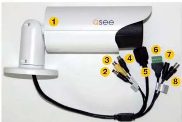
In addition to its video surveillance functions, the QCN8001B is able to accept input from other devices and either pass their signals back to an NVR, or utilize them to trigger recording or alert actions when it is being used in a stand-alone role. The camera has 32GB of internal memory allowing it to record video and still images without the need for an NVR.
By using the audio input and output to connect both a microphone and speaker - and with similar audio equipment on the user's end, two-way communication can take place. Two alarm sensors can be connected to the alarm block with a single output to an audible alarm, an external alarm input or to a DVR. When used with an NVR or on a network, the alarm signal can trigger recording and its signal can be transmitted via the Cat 5 cable to an NVR.
text_image
Qsee 1 2 3 4 5 6 7 8PICTURE 1-3
| # Item Function |
| 1 Storage Internal 32GB memory |
| 2 Reset Resets camera if user is locked out. |
| 3 Audio In Input for optional microphone |
| 4 Audio Out Connect to speaker |
| 5 RJ45 (Ethernet) Port For network connectivity, video output and power input (via POE). |
| 6 Alarm 2 Alarm Inputs 1 Output |
| 7 Power For use without POE |
| 8 Video Out BNC video output (for testing |
ADJUSTING THE LENS
The QCN8001B has a lens that can be manually adjusted between 3.3mm and 12mm. The 3.3mm setting provides a 67° field of view. The 12mm setting enlarges subjects by approximately three times compared to the 3.3mm configuration, with the field of view narrowing to 22°.
The camera is set at the factory to the 3.0mm position. To adjust the lens, you will have to first remove the black cover at the front of the camera by twisting it counter-clockwise. Take care not to damage the cover or the threads during this step.

natural_image
Close-up of a hand holding a black cylindrical device with a red downward arrow indicator (no text or symbols visible)PICTURE 1-4
Once the cover has been removed, you can adjust the zoom and focus using the two knobs located on the lens body behind the LED circuit board. You may need to loosen them by twisting the knob counter-clockwise before making the adjustments. Do not apply excessive force to the knobs as they can snap off, leaving your camera unable to be adjusted.
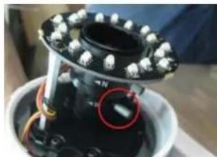
natural_image
Close-up of a mechanical device with white spherical components and a red circular annotation highlighting a specific area (no visible text or symbols)PICTURE 1-5
It is recommended that you have some way to view the camera's view while making the adjustments to ensure that the image is properly in focus and includes the entire area that you wish to monitor. This can be done using a camera tester connected to the BNC Video Out plug or by connecting it to an NVR where you can monitor it using the video display. A third method would be by connecting the camera to a network using the steps described in Chapter 2 and then accessing it remotely using a mobile device with a sufficiently large screen clarity. However, with this method it is important to keep in mind that mobile devices use the lower quality substream video so final adjustments may still need to be made.
QCN8001B Specifications
| System | Main Processor Texas Instruments DaVinci high-performance DSP | |
| OS LINUX | ||
| System Resources Supports simultaneous real-time network, local record, and remote operation | ||
| User Interface Remote operation through Web Service and PSS | ||
| System Status SD card status, bit stream stats, log, and software version. | ||
| Image Sensor 1/3" 2.0 Mp SONY progressive scan Exmor CMOS | ||
| IR LEDs 18 | ||
| Max IR range 65° | ||
| Min. Illumination 0.1LUX/F1.6 (color), 0.01LUX/F1.6 (b/w), 0LUX (w/IR) | ||
| Lens Auto-Iris 3.3-12mm@F1-6 | ||
| Video | Pixel 1920x1080 (1080p) | |
| Day/Night Mode Automatic | ||
| Auto Aperture DC drive | ||
| Gain Control Fixed/Auto | ||
| White Balance Manual/Auto | ||
| Exposure Mode | Manual/Auto NTSC: 1/4-1/10000 | |
| Video Comp.Standard | H.264/JPEG/MJPG | |
| Video Frame Rate | NTSC: Main stream 1080P @30fps, 1.3M @30fps, 720P @30fps; Substream 704x480@30fps | |
| Video Bit Rate | H.264 56Kbps-8192KbpsMJPG is adjustable along with bit rate | |
| Video Flip | Supported | |
| Snapshot | 1f/s snapshot. Files saved as JPG | |
| Privacy Mask Maximum 4 privacy zones supported | ||
| Video Adjustment | Brightness, contrast, hue, saturation and gain | |
| Video Info | Channel title, time, motion detection, masking | |
| Motion Detect | 396 (18x22) zones. Six sensitivity levels. Motion detection activation options: alarm, recording, snapshot, log and e-mail | |
| Audio | Audio Output 1-channel RCA | |
| Bidirectional Talk | Reuses first audio input channel | |
| Audio Bit Rate | 128/64/10.2 Kbps | |
| Audio Comp. | G.711a/G.711u/PCM | |
| Network | Network | 1-channel wire Ethernet port, 10/100 Base-T Ethernet |
| Network Protocols | Standard HTTP, TCP/IP, ARP, IGMP, ICMP, RTSP, RTP,UDP, RTCP, SMTP, FTP, DHCP, DNS, DDNS, PPPOE, UPNP, NTP, Bonjour, SNMP. | |
| Remote Operation | Monitor, PTZ control, system setup, file download, log information, maintenance and upgrade. | |
| Recording & Backup | Recording Priority | Manual>External alarm >Video detect>Schedule |
| Local Storage 32GB internal | ||
| Backup | Remote through PSS | |
| Auxiliary Connectors | Video Output | 1-channel BNC analog video out |
| Audio Input | 1-channel RCA | |
| Audio Output | 1-channel RCA | |
| Alarm | 2-channel input, 1-channel output | |
| Power | Power | Through RJ45 connector when connected to POE or 12v .5A through aux. power connector |
| Consumption <10W | ||
| Env. | Temperature | 15F to 140F |
| IP Rating | IP66 | |
| Humidity | 10-90% | |
QCN8002D
PICTURE 1-6

natural_image
Close-up of a white Qsee security camera with visible lens and control buttons (no text or symbols on the device itself)| System | Main Processor Texas Instruments DaVinci high-performance DSP |
| OS LINUX | |
| System Resources Supports simultaneous real-time network, local record, and remote operation | |
| User Interface Remote operation through Web Service and PSS | |
| System Status SD card status, bit stream stats, log, and software version. | |
| Image Sensor 1/3" 2.0 Mp SONY progressive scan Exmor CMOS | |
| Min. Illumination 0.1LUX/F1.6 (color), 0.01LUX/F1.6 (b/w), 0LUX (w/IR) | |
| Lens Auto-Iris 3.6@F1-6 | |
| Video | Pixel 1920x1080 (1080p) |
| Day/Night Mode Automatic | |
| Auto Aperture DC drive | |
| Gain Control Fixed/Auto | |
| White Balance Manual/Auto | |
| Exposure Mode Manual/Auto NTSC: 1/4-1/10000 | |
| Video Comp.Standard H.264/JPEG/MJPG | |
| Video Frame Rate NTSC: Main stream 1080P @30fps, 1.3M @30fps, 720P @30fps; Substream 704x480@30fps | |
| Video Bit Rate H.264 56Kbps-8192KbpsMJPG is adjustable along with bit rate | |
| Video Flip Supported | |
| Snapshot 1f/s snapshot. Files saved as JPG | |
| Privacy Mask Maximum 4 privacy zones supported | |
| Video Adjustment Brightness, contrast, hue, saturation and gain | |
| Video Info Channel title, time, motion detection, masking | |
| Motion Detect 396 (18x22) zones. Six sensitivity levels. Motion detection activation options: alarm, recording, snapshot, log and e-mail |
| Audio | Audio Output 1-channel RCA | |
| Bidirectional Talk | Reuses first audio input channel | |
| Audio Bit Rate | 128/64/10.2 Kbps | |
| Audio Comp. | G.711a/G.711u/PCM | |
| Network | Network | 1-channel wire Ethernet port, 10/100 Base-T Ethernet |
| Network Protocols | Standard HTTP, TCP/IP, ARP, IGMP, ICMP, RTSP, RTP,UDP, RTCP, SMTP, FTP, DHCP, DNS, DDNS, PPPOE, UPNP, NTP, Bonjour, SNMP. | |
| Remote Operation | Monitor, PTZ control, system setup, file download, log information, maintenance and upgrade. | |
| Recording & Backup | Recording Priority Manual>External alarm >Video detect>Schedule | |
| Local Storage 32GB internal | ||
| Backup | Remote through PSS | |
| Auxiliary Connectors | Video Output | 1-channel BNC analog video out |
| Audio Input | 1-channel RCA | |
| Audio Output | 1-channel RCA | |
| Alarm | 2-channel input, 1-channel output | |
| Power | Power | Through RJ45 connector when connected to POE or 12v .5A through aux. power connector |
| Consumption | <10W | |
| Env. | Temperature | 15F to 140F |
| IP Rating | IP66 | |
| Humidity | 10-90% | |
CONNECTING IP CAMERAS
CHAPTER 2
2.1 WHAT ARE IP CAMERAS?
Internet Protocol (IP) or Network cameras differ from conventional video cameras in that each is a stand-alone device with a built-in processor of its own. Rather than being processed and encoded on the recorder, the video is instead processed and encoded on the camera itself before being sent to the recorder. The onboard processor allows the camera to operate on its own with the video being available directly from the camera itself. The video can be recorded onto internal memory (depending on model), sent to an FTP drive, accessed by a computer or be streamed directly to a Digital Network Video Recorder (NVR) using standard network protocols.
When it is connected to the NVR - whether locally, through a network or over the Internet the NVR treats an IP camera as a peripheral device with the NVR serving as the control interface and recording system.
Q-See's QC-series NVRs feature an industry-exclusive built-in Power Over Ethernet (POE) block that allows you to connect up to four IP cameras directly to it up to 200 feet away using RJ-45 (Ethernet) cables without the need to purchase a separate power block or to locate the cameras near power outlets. The Ethernet cable will both power the camera and deliver the video signal to your system. Cameras beyond the number of POE ports, or those located away from the NVR will require a separate power source, such as from the powered port of a POE hub, or from a power supply. This power source must be located between the camera and the network. It is not possible to power a camera through a network or over the Internet using a POE port.
Cameras connecting to your system over a network (local or Internet) will also ultimately connect through your network's router and their signal will be received by the NVR through its Network port. Cameras located outside of the network, and those being used as stand-alone devices, will be accessed by using their web address - whether by entering it into the NVR, a web browser, or through a surveillance program.
2.2 CONNECTING AN IP CAMERA
Your IP camera delivers video through a standard Cat 5, 5A or 6 Ethernet cable connected to the RJ-45 socket at the end of the cable leading from the camera. Under most conditions, power is delivered to the camera through this cable when it is connected to a POE block. Regardless of how it is connected to the NVR, it is best to use a continuous length of cable, whenever possible, rather than multiple short segments as each intervening connection could result in a small loss of power and signal.
The following directions are for connecting your IP camera(s) to one of Q-See's QC-Series NVRs with a built-in POE block of powered Ethernet ports. If you are using another brand of NVR, please consult that system's user manual.
STEP 1. Connect one of the long Ethernet cables to the socket on the wire leading from the camera.

natural_image
Close-up of hands holding two blocks, one with a small label (no visible text or symbols)PICTURE 2-1
STEP 2. Plug the other end of the Ethernet cable into any of the Power over Ethernet (PoE) ports on the back of the NVR or into a stand-alone POE block.
In the latter cases, the camera will also need to be connected to a network.
STEP 3. Repeat for additional cameras.
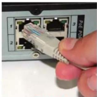
natural_image
Close-up of a hand inserting a PoE POP Ethernet cable into a network interface (no text or symbols visible)PICTURE 2-2
Using the Power Over Ethernet Block
Your NVR's POE block will power up to four cameras while receiving their video signals. This is the primary and preferred method to connect cameras to your NVR. This feature cannot be expanded through use of a network switch. These ports are also not to be used to connect the NVR to a network router. When an IP camera is connected to the NVR through the POE port, it will receive power immediately, but there may be a delay of up to a minute before the camera's signal appears on the screen as the system establishes connectivity.
If you are unsure, and if your camera has infrared LEDs, you may cup your hand over the lens area to activate the infrared night vision mode. You will see a faint red glow from the LEDs confirming that the camera has power.
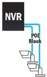
text_image
NVR POE BlockPICTURE 2-3
CAMERAS CONNECTED THROUGH A NETWORK
There are two types of networks – local (LAN or Intranet) and Internet (or WAN). Cameras can be accessed by the NVR over both types.
Local Networks
For cameras positioned too far away to reasonably run a network cable directly to the NVR, you can connect it to the same network as the NVR and the system will be able to access and use them.
Ultimately, each camera will have to connect to the same router that the NVR is connected to. They will need to be connected to a power source on their side of the network - preferably a POE - as the POE block on the NVR itself is unable to provide power through the network.

flowchart
graph TD
    A["NVR"] --> B["Network-Port"]
    B --> C["POE Block"]
    C --> D["Server"]
    B --> E["Router"]
    E --> F["POE"]
PICTURE 2-4
Alternatively, if your NVR was bundled with cameras, they may include a power input as additional power option. You will need to acquire a power adapter that matches the ratings listed on the camera itself if you are not connecting them to a POE.
The NVR will connect to these cameras through the same cable that it uses to communicate with the network.
Connections Over the Internet
A third connection option is via the Internet. This method is more complicated, but it allows the user to view cameras that are located in a completely different building – or region – from the NVR itself. In essence, your NVR will be remotely monitoring those cameras. As such, the user will need to forward ports using the IP Tool software included on the Manuals and Software
CD to obtain the IP address for any camera that will be accessed over the Internet. Full instructions are covered in Chapter 2.

flowchart
graph TD
    A["NVR"] --> B["Network Port"]
    B --> C["POE Block"]
    C --> D["Internet"]
    D --> E["Router/Modem"]
    E --> F["POE"]
    F --> G["Network Port"]
    G --> H["POE Block"]
    H --> I["Network Port"]
    I --> J["POE Block"]
    J --> K["Network Port"]
PICTURE 2-5
2.2 ADDING AND REMOVING CAMERAS IN YOUR SYSTEM
LOCAL CAMERAS
Once you have connected your cameras, you will need to add them to your system's display. For cameras connecting to one of Q-See's QC-Series NVRs, they will automatically appear on-screen shortly after being plugged in. Cameras will be assigned to the first available channel by the NVR in this case, regardless of which port in the block that they were connected to. These cameras can only be removed from your display by physically disconnecting the cameras from the NVR.
CAMERAS ON THE SAME NETWORK
Cameras sharing the network with the NVR will not automatically connect. There are three ways to connect them on a QC-Series NVR. The first two methods are by either using the Add Camera icon in the Live View window, or right-clicking within it. The third method uses the Remote Device window located in the Main Menu.
Add Camera
Moving the cursor to the center of any empty channel will reveal the Add Camera icon shown in Picture 2-6. Clicking on this will open a window listing available cameras.

natural_image
Simple gray circular background with a white plus sign in the center (no text or symbols)PICTURE 2-6
Clicking on IP Search will refresh this list. Simply click on the desired camera from the list and it will become the camera for that channel. Please note that it is possible to load a camera which is already in use by another channel. In which case, you will have two identical channels.

text_image
REMOTE DEVICE 2 IP Address Port Device ID Manufacturer Type 1 IP 1.06 1 YAC000896 Prove PCS4H0218 2 IP 1.06 2 YAC000897 Prove PCS4H021PICTURE 2-7
QC NVR REMÔTE DEVICE MENU
Use of remote IP cameras connected to a network - whether local or remote - requires your NVR to be connected to a router. It also requires that the cameras are connected to a router as well - even if it isn't the same one as the NVR. If you intend to connect to devices that are located outside of your local network, then this router must be able to access the Internet. Instructions for connecting your system to the Internet are presented in the Remote Monitoring Guide that also came on the CD with your system. It is also available from our online resource at www.Q-See.com/Support.
Similarly, the remote devices must be able to communicate with the local network or Internet. This will be covered in Section 2.3. You will need to follow the instructions in that chapter in order to obtain an IP address for any cameras that will be accessed over the Internet. Once you have connected your cameras to a router you can connect to them using the Remote Device window.
This window can be reached by clicking on the Remote Device icon in the Main menu...

text_image
MAIN MENU SEARCH INFO SETTING REMOTE DEVICE ADVANCED BACKUP SHUTDOWNPICTURE 2-8
...or through the Shortcut menu by right-clicking on the screen and selecting Remote Device.
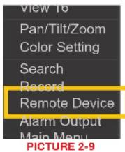
text_image
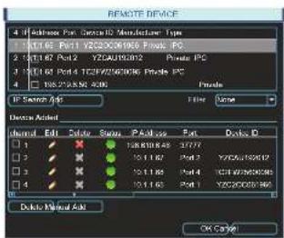
View 16 Pan/Tilt/Zoom Color Setting Search Record Remote Device Alarm Output Main Menu PICTURE 2-9When the window opens, you will be presented with a list of all connected devices in the lower portion. This section, marked Device Added, indicates the status of each device along with other information about it.
text_image
REMOTE DEVICE 4 IP Address For: Digital Modulator Type 1 101.16 Port1 YZCAU200200000000000000000000000000000000000000000000000000000000000000000000000000000 1 101.16 Port2 YZCAU200202 Private PC 1 101.16 Port3 YZCAU200206 Private PC 1 101.16 Port4 YZCAU200208 Private PC Private PC IP Service Add File Name Device Added Internal Edit Delete Status Paste Pack Delete ID 1 1 1 1 1 1 1 1 1 1 1 1 1 1 1 1 1 2 1 1 1 1 1 1 1 1 1 1 1 1 1 1 3 1 1 1 1 1 1 1 1 1 1 1 1 1 4 1 1 1 1 1 1 1 1 1 1 1 1 Delete Manual Add OK CancelPICTURE 2-10
| Icon Meaning | Description | |
| Editable | You may edit the settings on this device by double-clicking on it | |
| Cannot Delete | This device is connected directly to the NVR and must be physically unplugged to be removed from this list. | |
| Removable | This device may be deleted from the list by checking the box next to it and clicking on theDeletebutton below. | |
| Device Status OK | The connected device is operating normally. | |
| Device Error | There is an issue with the connected device that is preventing it from operating normally. | |
Clicking on IP Search under the upper portion of the window will generate a list of all devices that the NVR was able to locate - both directly connected as well as connected to the same network as your system. Items showing a short IP address beginning with "10" are cameras directly connected to the NVR and who's IP addresses were assigned by the NVR itself. Care should be taken that you do not attempt to connect a device that is already connected to the system as it will create a duplicate video feed and could cause connectivity issues.
Edit
Double-clicking on a device in the Device Added portion of the window will display information regarding the connected remote device. Making any changes within this window will not change anything on the camera or remote device itself. To make those changes, you will need to access the camera or other remote device (such as a DVR) directly, or through one of the remote methods described in the Remote Monitoring Guide.
Once you have made those changes, you will need to update the user name and password within the Edit window. Failing to change these in this window will result in an on-screen message about incorrect password and may lock you out of the IP camera for a period of 30 minutes in the case of QC-Series cameras - other brands may vary.
It is important that you do not remove the device you are making the changes upon from the list of connected devices before editing the information in the Edit window. If you later remove the device from the list and wish to reconnect, you will need to do so using the Manual Add feature as described below.
Similarly, if you already know the IP address and port of the camera, you can use the Manual Add feature.

text_image
REMOTE DEVICE 1. Hosts Port Device 2. Networker Type 2. Open Port: Any OS/OS/OS/OS/OS/OS/OS/OS/OS/OS/OS/OS/OS/OS/OS/OS/OS/OS/OS/OS/OS/OS/OS/OS/OS/OS/OS/OS/OS/OS/OS/OS/OS/OS/OS/OS/OS/OS/OS/OS/OS/OS/OS/OS/OS/OS/OS/OS/OS/OS/OS/OC PC PC Channel 1 Manufacturer Private IP Address: 80% via 500 MHz TCP Port 3265 User admin Password 000000000000000000000000000000000000000000000000000000000000000 2.2 2.4 3.1 4.1 5.1 6.1 7.1 8.1 9.1 10.1 11.1 12.1 13.1 14.1 15.1 16.1 17.1 18.1 19.1 20.1 21.1 22.1 23.1 24.1 25.1 26.1 27.1 28.1 29.1 30.1 31.1 32.1 33.1 34.1 35.1 36.1 37.1 38.1 39.1 40.1 41.1 42.1 43.1 44.1 45.1 46.1 47.1 48.1 49.1 50.1 51.1 52.1 53.1 54.1 55.1 56.1 57.1 58.1 59.1 60.1 61.1 62.1 63.1 64.1 65.1 66.1 67.1 68.1 69.1 70.1 71.1 72.1 73.1 74.1 75.1 76.1 77.1 78.1 79.1 80.1 81.1 82.1 83.1 84.1 85.1 86.1 87.1 88.1 89.1 90.1 91.1 92.1 93.1 94.1 95.1 96.1 97.1 98.1 99.1 100.1PICTURE 2-11

IMPORTANT! To avoid connection issues, you should not change the information within the Edit window unless you have first made those changes to the remote device itself.
The lower portion of the window shows all devices currently connected to your NVR. If all of your channels are occupied, you will need to delete one of the connected devices from this list by selecting the check box next to it and clicking delete. Items with a gray "X" are directly connected to your NVR and may only be removed by physically disconnecting them from your system.
Clicking on the IP Search button will create a list of all remote devices that the NVR was able to detect. You may limit this search to only IP cameras by selecting IPC in the Filter pull-down. Items being accessed by your NVR over the Internet will not appear in the list at the top of the window. They must be added manually (see below).
If you have an available channel, you may add a device by selecting the check box next to it and then clicking Add. Please note that if you changed the default user name and password for your camera(s) in the Web Service application as described in Chapter 3, you will need to use the the Manual Add feature instead.
2.3 CONNECTING YOUR CAMERA TO A REMOTE NETWORK
As was mentioned in the previous section, cameras connected to the same network router as the NVR can be discovered by that system and added. Cameras on a different network require additional steps to be connected to an NVR, and these same steps are needed if one is going to be accessing the camera only using a computer or mobile device.
First and foremost, you will need to physically connect your camera to a router. This router can be part of an existing network of computers, or it can be the router/modem supplied by your Internet Service Provider (ISP) to connect you to the Internet. This connection will be made by plugging the other end of the Ethernet cable that you connected to the camera into a router or into an Ethernet port that connects to a router.
You cannot connect the camera to the Internet through a modem because there is no method available to cause the modem to dial out to the ISP. Your camera will need to be directly connected to its own power supply - whether it is a power adapter or a Power Over Ethernet (POE) block. In the case of the latter, the POE block will then connect to the router or network.
Your camera is not designed to be connected wirelessly to a network. It is also recommended that the router that the camera is connected to should be connected directly to the Internet rather than to another router if Internet access is desired as multiple routers can create problems with connectivity. You will also need to have a computer connected to the same router - at least temporarily - to make certain settings. If, after following the instructions you are still not able to access your NVR, please see Section 2.4 Troubleshooting Network Connections later in this chapter.
In order to access your camera over the Internet, you will have to determine its IP address. Each device on a network - both a LAN or the Internet - has a specific IP address. This address is what allows different devices on the network to communicate with each other. You will also need to confirm that two ports, or openings, have been permitted by your router to allow communication to and from your camera.
BEFORE YOU GET STARTED
You will need to have:
- Your router's brand, model number and manual. The manual is also usually available on your router's manufacturer's website.
- The "Manuals and Software" CD that came with your camera. It contains necessary software and links to other important programs which are mentioned in this guide.
- Your router's password (the default password should be in your router's manual).
- Your router's Gateway address.
If your camera is able to automatically connect to your network, you will only need your router's Gateway address to connect to your camera from outside of the local network. However, if your camera is unable to connect automatically, you will need this information in order to make the connection.
OBTAINING IP INFORMATION USING IPCONFIG IN WINDOWS
You will need to get your router settings to not only create an IP address, but for the Default Gateway information as well.
To get the router settings:
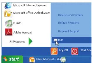
STEP 1. To access the router's settings you will need to enter the Command (CMD) panel on a computer also connected to the same router.
A. WINDOWS XP - Select Run from your Windows START menu (lower left of screen) and type "cmd" after the prompt.
text_image
Microsoft Internet Explorer Microsoft Office Outlook 2037 iTunes Adobe Acrobat All Programs Devices and Printers Default Programs Help and Support Run Log Off Shut Down start Irisus Microsoft...ITunesPICTURE 2-12
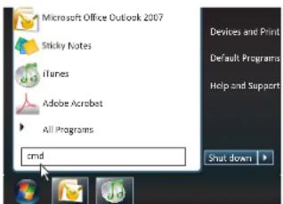
B. WINDOWS VISTA and WINDOWS
7 - Click on the START menu (Windows icon) in the lower left of your screen. Type "cmd" into the field that says, "Search programs and files" and hit ENTER or click on the magnifying glass icon.
text_image
Microsoft Office Outlook 2007 Sticky Notes iTunes Adobe Acrobat All Programs cmd Devices and Print Default Programs Help and Support Shut downPICTURE 2-13
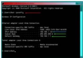
STEP 2. Type "ipconfig" at the prompt (Red arrow in Picture 2-14) to access router settings.
STEP 3. Write down the Default Gateway number (bottom green arrow).
text_image
Microsoft Windows [Version 6.9-8001] Copyright (c) 2006 Microsoft Corporation. 451 rights reserved. ©:\UsersHost\specify Windows IP Configuration Ethernet adapter Local Area Connection: Connection:specific DNS Suffix : Dps local Local Site (DNS) Address : Web: https://www.dsn.com/ Dsn Address : 103.108.1.131 Color: 201-205-206-5 Default setting : 103.108.1.1 Form) adapter Local Area Connection 6: Media Data : Media Occasionant Connection:specific DNS Suffix : Dps local ©:\UsersHost\PICTURE 2-14
OBTAINING IP INFORMATION USING A MAC
The easiest method for locating the router's Gateway address for Macintosh is through the computer's Network window.
STEP 1. Click on the System
Preferences icon at the bottom of the Macintosh's screen.

PICTURE 2-15
STEP 2. Click on the Network icon.
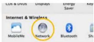
text_image
COS & DVUS Displays Energy Saver Key Internet & Wireless MobileMe Network Bluetooth ShuPICTURE 2-16
STEP 3. Make sure that your network connection is highlighted in the list of connections to the right of the main part of the Network window and that its status reads "Connected." The Router's IP address will be displayed.

text_image
Networks Location Automatics Status: Connected Show to any specific file and top file of (01.0123.25) Configure Web: Link-SPC IP Address: 81.918.623.289 Server Address: 703.774.303.9 Server: 81.918.623.28 USB Server: 81.918.623.28 Search Domain: 0.0000000000000000000000000000000000000000000000000000000000000000000000000000000000000000000000000 Advanced... Close by link to power for further changes. Add to...PICTURE 2-17
TESTING THE CONNECTION
Your camera features UPnP (Universal Plug 'n Play) connectivity. This allows network devices to be automatically added to the network and communicate with other devices within it without additional setup. If your Network router has this feature - and it is turned on - your camera may be accessible from the moment you connect it to the network.
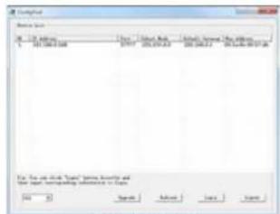
To test this, once you have connected the IP camera to a network, you will need to run the ConfigTool software on a computer connected to the same router.

PICTURE 2-18
This Windows software is located in the Software folder on the CD that came with your system. Macintosh computer users will need to use the Search Device function within the Device Manage window in PSS to locate the camera. PSS is covered in
Chapter 4
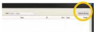
PICTURE 2-19
When ConfigTool launches, it will produce a list of all QC-Series IP cameras that are connected to the same network. This will confirm that your camera has been successfully added to your network.
To ensure that the camera and the connection are operating properly, right click on the camera's name in the list.
A pop up window saying, "Open Device Web" will open. Click on it to open a browser window.
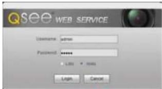
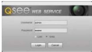
When the browser window has opened, you will be presented with a login screen for the Q-See Web Service. Since you're on the same network as the camera, you will want to select LAN from the options at the bottom of the screen.
text_image
File Set 01-24 April 2007 15:30:00:348 Date: 2015.09.23 File Path: 15.00.24 File Date: 2015.09.23 File Name: 15.00.24 File Type: Open Text File Status: Open Text Save As... Save As... Save As... For the end of this period, you have already been the year, or any other year is required.PICTURE 2-20
text_image
Qsee WEB SERVICE Unknown: admin Password: ****** • Login • Remove Login CancelPICTURE 2-21
The default username and password are admin and admin. It is recommended for security reasons that you change the password before you add the device to your NVR. See Section 3.6 for instructions on modifying the password on your camera.
Internet Explorer users may be asked to download an ActiveX plug-in from Q-See International, Ltd. Firefox and Chrome users may be asked to allow QuickTime to run. In these cases, you should allow the required plugins to operate. In some cases, you will be returned to the log in screen after the plugin has loaded. This is normal.
Although ConfigTool is Windows only, the Web Service browser program will operate on Macintosh computers as well. To access your camera without ConfigTool, simply enter the camera's local IP address into the browser window on a computer located on the same network.
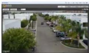
After you log in, you should see live video from your camera. This confirms that your connection and camera are operating optimally. You may also use the Web Service program to access your camera separately from your NVR. The camera can also be accessed through the PSS software included on the CD. These are both covered in the next chapters.
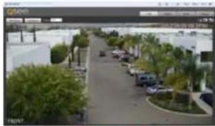
natural_image
Street view with parked cars and palm trees along a paved road (no visible text or signage)PICTURE 2-22
Once you have confirmed that you can access your camera on a local network - and if you wish to access it from over the Internet - you will need to confirm that the camera's ports have been opened as well as obtain the camera's Internet IP address
If you are unable to see video from your camera, you should check all connections and ensure that your computer software is operating properly. You may also wish to try to connect using a different browser or computer if the problem persists. Instructions for opening ports and troubleshooting connection issues are provided in the next section.
OPENED PORTS AND INTERNET IP ADDRESS
Just as with your NVR, you will need to confirm that your ports are open and that your camera is accessible from the Internet. You will also need to get the Internet IP address which you will use to connect to the camera outside of its local network.
Confirming that the ports have been opened
To confirm that your ports have been forwarded successfully, go to www.canyouseeme.org using a computer connected to the same router as the camera.
STEP 1. Enter "85" into the box labeled "What Port?"
STEP 2. Click on the Check button.
STEP 3. You should see a green "Success" message. If not, return to ConfigTool and double-click on the camera in the list. Change port 85 to 81 or 83 and click Apply to save your changes before checking using that new number on CanYouSeeMe.
STEP 4. Repeat for port 37777. If there is a problem with port 37777, then try 37000 in the same manner as above.

text_image
Browser - Windows Internet Explorer http://cityyouseeme.org/ Open Port Check Tool CanYouSeeMe.org - Open Port Check Tool This page will have a free utility for monthly screening, port is open on board, it is useful for users who will use a mask or a mask to be blocking their port. Your IP: 81.919.622.24 What Was? Close: Success: I can see your service on 81.919.622.24 on port (85) Your ISP is not blocking port 85PICTURE 2-23
Obtaining Internet IP address
This website will also display your Public IP address near the top of the page above the box where you entered your port number. This is the first part of the number which you will use to access the IP camera using your NVR, the PSS software, the Web Service browser app or your mobile device from outside of your local network (away from the building in which your NVR is located). The second part is the first port number that you confirmed was open. Using the number shown in the image above, you would enter http://81.919.622.24:85 with 85 being the opened port. If you used a number other than 85 for the first port, you will use that instead, placing it after the colon ( ^1-5 ) in the address.
Be sure to record this address for use at your NVR. If you had to use a different port than 37777 you will need to record that as well.
2.4 TROUBLESHOOTING NETWORK CONNECTIONS
OPENING PORTS
The most common factor causing network connection issues is for communication between the device and a device outside the network to be blocked. The router's built-in-firewall is designed to keep malicious users and software out of the network. At times, this can also block legitimate connections. To avoid this, routers can allow communication to pass through specific ports within the firewall. These "virtual tunnels" only allow access to specific devices within the network. Properly managed with passwords and other safeguards, these do not pose a threat to the security of the network.
If your network's router has the UPnP feature turned on, it and the camera should "discover" each other on the network in less than a minute. Ports 85 and 37777 will be "forwarded" to the camera's local network IP address, allowing it to communicate with the Internet. The former allows you to control the camera, while the latter port is used by the camera for the video stream.
However, some brands of routers, such as the 2Wire used by AT&T for it's Uverse service do not include this feature. In this case, the ports will need to be manually forwarded using one of the methods described on the next few pages. You will only need to use one of these methods - which are the same if you are using a Macintosh or Windows PC. If you are still unable to connect your NVR to the Internet using any of these procedures, the likely cause is the presence of multiple routers on your network. Solutions to overcome that situation are presented at the end of this section.
Regardless of the method you use, you will need to get your router's Public (Internet) IP and Gateway addresses in order to log into the router, and eventually connect to the camera.
Option 1: UPnP
Check your router's manual to confirm the presence of the UPnP feature. You may need to log into your router to turn it on. There are legitimate reasons to disable UPnP, but you may wish to enable it briefly in order to allow the camera to connect. Once you've confirmed that the camera's ports have been opened and you've set the camera to use a Static IP address as described later in this section, you can disable UPnP.
The location of the UPnP settings within your router vary by brand and model. Consult your router's manual to locate and enable this feature before continuing.
Option 2: Opening Ports Using DMZ
The exact location of DMZ within the router's settings vary by manufacturer so please consult your router's manual for the location of this feature. The method for accessing your router's settings, however, is pretty standard.

NOTE! If you are an AT&T Internet or Uverse customer, you should follow the instructions laid out in Option 3 as they specifically apply to the brand of router used by AT&T.
STEP 1. On a computer connected to the same router as your camera, open a web browser and enter the Gateway (Router's IP address) into the browser window's address bar to access your router.

PICTURE 2-24
STEP 2. Locate the DMZ settings in your router. Each manufacturer is different so please consult your router's manual for the location of this setting. Two examples are shown at right.
STEP 3. Enable DMZ.
STEP 4. Enter the NVR's IP address.
STEP 5. Click on Apply or Save to preserve your settings.
Leave your router control panel open as you will need to obtain DNS information from your router in Section 1.5 Domain Name System (DNS). You should now proceed to the section entitled Confirming that Ports are Opened.
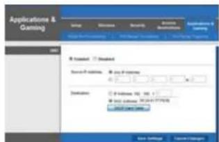
text_image
Applications & Gaming Default Remove Security Ordering Settings Forward Standard Service P Options Play P Options Destination Set Options: 100, 100, 100, 100, 100, 100, 100, 100, 100, 100, 100, 100, 100, 100, 100, 100, 100, 100, 100, 100, 100 Edit Settings Custom SettingsPICTURE 2-25

text_image
DOS POST DOS POST Settings The DOS (Downloaded DOS) option: This can use a single computer on your network via the DOS. If you can use a single computer, then call to an email address or a network user at the DOS. The DOS is available in this case.PICTURE 2-26
Option 3: Opening Ports Using DMZ on 2Wire Routers
2Wire brand routers are currently the exclusive router used for AT&T's Uverse and other Internet servers. Their configuration protocols are different enough that you should follow these instructions rather than the generic router instructions in Option 2 if you are an AT&T customer.
STEP 1. On a computer connected to the same router as the IP Camera, open a web browser and enter the Gateway (Router's IP address) into the browser window's address bar to access your router.
STEP 2. Click on the Settings tab and then Firewall. Once in Firewall, click on Applications, Pinholes and DMZ.
STEP 3. In the Select Your Computer area, locate your camera's IP address and click on it.
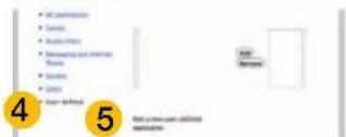
STEP 4. Scroll down to select User Defined.
STEP 5. Click on Add a new user-defined application.
STEP 6. In the box labeled Application Profile Name, enter "IP Camera".
STEP 7. Ensure that TCP is selected.
STEP 8. Enter 85 in the From and To boxes for Port (or Range).
STEP 9. Leave the next two boxes blank to use the default settings.
STEP 10. Click on Add to List. Your router will require you to log in to accept the settings. If you have not created your own password for your router, it is the 10-digit System Key printed on the label on your router between the square brackets "[]".

PICTURE 2-27


text_image
• Add parameters • Save • Active action • Newspaper and Internet Theme • Update • Gross • Save defined 4 5 Add your own functions maintains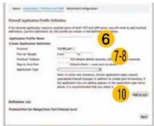
text_image
Formal Application Profile Definitions If the should applicable means to multiple parts of both TCP and TCP panels, we will need to add multiple definitions. Current definitions for this profile are shown in the following table: Application Profile Name Create Application Definition Project Form Project Part Project Timeout Run to Start Part Application Type 7-8 7-8 Description: Note: In some terms, certain application tables may be extracted from https://www.rsc.org/1000000000000000000000000000000000000000000000000000000000000000000000000000000000000000000000000 10 Definition List Processed Part (Ranged) Host Part Timeout (End) NextPICTURE 2-28
STEP 11. Once your settings have been confirmed, repeat Steps 8-10, this time entering 37777 for the From and To ports.
STEP 12. Click on Back and then select Ip Camera from the list of Applications. Clicking on Add and then Save.
Leave your router control panel open as you will need to obtain DNS information from your router in Section 2.5 Additional Network Services.
Confirming That Ports are Opened
To confirm that your ports have been forwarded successfully, go to www.canyouseeme.org using a computer connected to the same router as the camera.
STEP 1. Enter "85" into the box labeled "What Port?"
STEP 2. Click on the Check button.
STEP 3. You should see a green "Success" message. If not, return to the NVR's Network window and, in the Network tab, change port 85 to 81 or 83 and click Apply to save your changes before checking using that new number on CanYouSeeMe. Afterwards, you will need to forward that new port using Option 2 or 3.
STEP 4. Repeat for port 37777. If there is a problem with port 37777, then try 37000 in the same manner as above.

text_image
CanYouSeeMe.org - Open Port Check Tool This page will show as this entry in her own service via a port or closed. It is required to see your IP with access to use a server or ISP to blocking the port. Your ISP: 81.919.622.24 What's it? Check Success: I can see your service on 81.919.622.24 on port (85) Your ISP is not blocking port 85PICTURE 2-29
This website will also display your Public IP address near the top of the page above the box where you entered your port number. This is the number which you will use to access the IP camera using a web browser; the PSS program or your mobile device from outside of your local network (away from the building in which your camera is located).

NOTE! If you are successful after changing from port 85, then you will need to add that to the IP address when accessing the camera via the Internet. If, for example, you changed to port 81, the address would now read 64.245.112.90:81
ISSUES WITH DHCP
As long as you are connecting your camera to a router with DHCP enabled, you should not have an issue connecting to your camera. The majority of routers do have the DHCP feature, but some users disable this feature and manually assign IP addresses to the devices on their network. The first step in resolving a connectivity issue, is to ensure that DHCP is active on your router. You will need to consult your router's manual for information on where this feature is located.
If you have disabled DHCP and prefer to manually assign IP addresses to your network devices, you may do so using the ConfigTool software. If you do not know the correct IP information, you can use the Windows ICONFIG command shown in Section 2.3 to obtain the needed information.
Double-click on the desired device to open the camera's Login window within Config Tool to open the IP Address Modification window.
Enter the IP address, default gateway and subnet mask.
Click OK to save, and you will see the information update in the Device List.
Right-click on the camera to open it in the Web Service browser program and proceed as described in Section 4.2, above.
Alternately, you may wish to turn on DHCP in your router long enough to allow the camera to obtain an IP address, which you can then change to Static in the Web Service's Network TCP/IP window. Enter the information into the proper fields in ConfigTool's IP Address Modification window.
Click OK to save, and you will see the information update in the Device List.

text_image
Response jus File 1.0 Options Name: User Book Address/Service To Address 2 100.000.000 1749 253.253.25 186.000.00 186.000.00 File 1.0 is closed "Open" before directory and the label representing information in Table.PICTURE 2-30

Right click on the camera to open it in the Web Service browser program and proceed as described in the next chapter.
MULTIPLE ROUTERS ON THE NETWORK
If you have tried the previous methods and are still unable to connect to your camera from outside of the local network, it is possible that there may be more than one router between your camera and the Internet. Having more than one router between the camera and the Internet will block communication to and from your device. The simplest remedy is to connect the camera to the router that directly connects to the Internet.
To find out the number of routers on your network, you will need to download a FREE router detection program.
STEP 1. Go to http://www.pcwintech.com/shanes-toolbox
STEP 2. Click on Detect Multiple Routers to begin the download.

text_image
RemoteScan Guide Shane's Guide Shane's Guide Shane's Guide Shane's Guide Shane's Guide Shane's Guide Shane's Guide Shane's Guide Shane's Guide Shane's Guide Shane's Guide Shane's Guide Shane's Guide Shane's Guide Shane's Guide Shane's Guide Shane's Guide Shane's Guide Shane's Guide Shane's Guide Shane’s Guide Shane’s Guide Shane’s Guide Shane’s Guide Shane’s Guide Shane’s Guide Shane’s Guide Shane’s Guide Shane’s Guide Shane’s Guide Shane’s Guide Shane’s Guide Shane’s Guide Shane’s Guide Shane’s Guide Shane’s Guide Shane’s Guide Shane’s Guide Shane’s Guide Shane’s Guide Shane's Guide Shane's Guide Shane's Guide Shane's Guide Shane's Guide Shane's Guide Shane's Guide Shane's Guide Shane's Guide Shane's Guide Shane's Guide Shane's Guide Shane's Guide Shane's Guide Shane's Guide Shane's Guide Shane's Guide Shane's Guide Shane's Guide Shane' The Guide is made by a user to access the website at www.xhase.com or a website for your own platform. It is also available in the website (http://www.xhase.com/1982). These are not listed on the website or any other platform. The website is available in the website or any other platform.PICTURE 2-33
STEP 3. Unzip the application to install it.
STEP 4. Click on the detect raters application to run it.

PICTURE 2-34
STEP 5. Click on CHECK NOW to detect how many Routers are in the network.
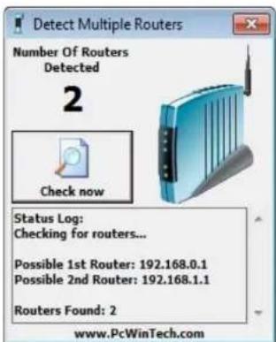
text_image
Detect Multiple Routers Number Of Routers Detected 2 Check now Status Log: Checking for routers... Possible 1st Router: 192.168.0.1 Possible 2nd Router: 192.168.1.1 Routers Found: 2 www.PcWinTech.comPICTURE 2-35
STEP 6. If there is only one router detected, and you are using UPnP, then you will need to turn off that setting and attempt to connect using DMZ as described in Section
1.2 Opening Ports.
If you are using DMZ, check to make sure that the UPnP option is turned off.
If Multiple Routers are Detected
If there are multiple routers, you will see a display similar to Picture 2-36.
If so, it may be preferable to connect your NVR and computer to the router that connects directly to the Internet. However, this is not always possible depending upon your particular situation.
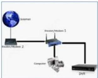
flowchart
graph LR
    A["Internet"] --> B["Router/Module 2"]
    B --> C["Router/Module 1"]
    C --> D["Computer"]
    D --> E["DVR"]
PICTURE 2-36
In this case, you will need to proceed with the next section and set up DMZ in the second router to allow communications to pass through it from the first. If only one router is detected you will need to consult your router's manual.
Setting Up DMZ in Router 2
STEP 1. Login into Router 1 by putting the IP of Router 1 into the Internet Explorer browser, as in the example shown in Picture 2-37 where the IP address of Router 1 is 192.168.0.1
STEP 2. Find the status page on the router settings that shows the WAN/Internet IP address and write it down this WAN IP address.
STEP 3. Log into the Router 2 by putting the IP of Router 2 into the Internet Explorer browser, as in example shown in Picture 2-37 where the IP address of Router 2 is 192.168.1.1
STEP 4. Find the DMZ page in the router settings.
STEP 5. Enter the WAN IP for Router 1 into the DMZ page and enable DMZ.

text_image
Detect Multiple Routers Number Of Routers Detected 2 Check now Status Log: Checking for routers... Possible 1st Router: 192.168.0.1 Possible 2nd Router: 192.168.1.1 Routers Found: 2 www.PcWinTech.comPICTURE 2-37

NOTE! If you do not have a DMZ setting in the router, check to see if there is a Bridge setting. If so, then use the Bridge setting instead of DMZ.
STEP 6. Save your changes.
You have forwarded the ports on the router to which the NVR is connected, to the IP address of the NVR, and set the second router to pass the connection to this router.
CONFIGURING ACTIVEX
Accessing your NVR using Internet Explorer is generally as simple as using an interactive website. Some users may need to configure Microsoft's built-in ActiveX controls prior to logging into their camera in order to ensure smooth operation. ActiveX is built into Internet Explorer to enable it use multimedia content. Sometimes, this can cause conflicts with security settings within the browser program itself.
Setting Up ActiveX Control
STEP 1. Open Internet Explorer
STEP 2. Click on Tools
STEP 3. Select Internet Options in the pull-down menu
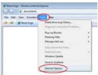
text_image
Bank Page - Windows Internet Options File Edit View Favorites Help Bank Page Delete Browsing History... Mis Tagging Connection Problems... Prop-up Director Winishing Filter Manage Add-on Subscribe to the Web... Host Discovery Windows Update Send to Onlink Internet OptionsPICTURE 2-38
STEP 4. Click on the Security Tab
STEP 5. Select Trusted Sites
STEP 6. Click on the Sites button

text_image
Internet Options General Security Privacy Content Connections Programs Advanced Select a zone to view or change web site settings. Internet Local Internet Restricted sites Trusted sites This zone contains websites that you trust not to manage your computer or your files. SinoPICTURE 2-39
STEP 7. Uncheck the "Require server verification (https:) for all sites in this zone" button.
STEP 8. Type the NVR's IP address (obtained during Network Setup) or DDNS domain name into the "Add this website to the zone:" box.
STEP 9. Click the Add button
STEP 10. Close the window.
STEP 11. Click the Custom level... button.
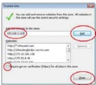
text_image
Trusted sites ✓ You can add and remove websites from this zone. All sites in the zone will use the zone's security settings. Add to website to the zone: 192.568.1.110 websites: https://m.nhouse.com https://s.broodingbirdp.mvnc.com https://173.15.156.138 https://173.52.8.46 http://173.52.8.46 Configure server verification (https) for all sites in the zone Add CancelPICTURE 2-40
text_image
Internet Options General Security Privacy Content Connections Programs Advanced Select a zone to view or change security settings. Internet Local Intranet Truited sites Annotated sites Trusted sites ✓ This zone contains websites that you trust not to damage your computer or your files. You have websites in this zone. Security level for the zone Custom Custom settings. - To change the settings, click Custom levels. - To use the recommended settings, click Default level. □ Enable (Protected Mode: http://www.123.com Internet Explorer) Custom level... Default level Event all zones to default level OK Cancel HelpPICTURE 2-41
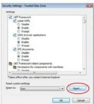
STEP 12. Pull down the "Reset to": menu button and select Low

text_image
Blank Page Security Settings - Trusted Site Zone Settings NET Framework Lower XML Disable Enable Prompt XML Browser applications Disable Enable Prompt MPS Documents Disable Enable Prompt NET Framework reliant components Permissions for components with manifests Enable * Takes effect after you restart Internet Explorer Reset custom settings Export to: Medium (default) Medium (default) None Reset... CancelPICTURE 2-42
STEP 13. Click the Reset button
STEP 14. Click "Yes" when asked, "Are you sure you want to change the setting for this zone?"
STEP 15. Click OK
STEP 16. Click Apply
STEP 17. Click OK
STEP 18. Close Internet Explorer
text_image
Security Settings - Trusted Sites Zone Settings XNET Framework Lower XAPS Disable Enable Prompt PAPS Browser applications Disable Enable Prompt APS documents Disable Enable Prompt XNET Framework-relevant components Permissions for components with Artifacts Options *Takes effect after you restart Internet Explorer Reset custom settings Event to: Low Reset...PICTURE 2-43
Open a browser window in Internet Explorer and enter the IP address or DDNS name (obtained in Section 1.1) into the address bar.
You will see a log in screen similar to that shown in Picture 2-44 or yellow alert bar at the top of the window asking for permission to open an ActiveX application. Allow it to install webrec.cab control to reach the sign-in screen.
Proceed to Chapter 3 for instructions on logging in and remote monitoring.
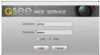
text_image
QSee WEB SERVICE User(s) admin Password ****** - Light CancelPICTURE 2-44
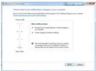
Troubleshooting: User Account Control for Windows Vista and Windows 7
Some users of computers using Windows Vista or Windows 7 operating systems may receive an error message informing of a codec that is missing or not installed. This conflict can be resolved by turning off User Account Control (UAC).
Windows Vista
STEP 1. Open the Control Panel (accessible by clicking on the Windows Icon in the lower left of your screen.
text_image
Microsoft Office Smart Devices [01] Dialysis of Speech Microsoft Office Smart (WIS) Smartset Smart Devices Smart Devices Smart Devices Smart Devices Smart Devices Smart Devices Smart Devices Smart Devices Smart Devices Smart Devices Smart Devices Smart Devices Smart Devices Smart Devices Smart Devices Smart Devices Smart Devices Smart Devices Smart Devices Smart Devices Smart Devices Smart Devices Smart Devices Smart Devices Smart Devices Smart Devices Smart Devices Smart Devices Smart Devices Smart Devices Smart Devices Smart Devices Smart Devices Smart DevicesPICTURE 2-45
STEP 2. Select User Accounts and Family Safety.
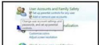
text_image
User Accounts and Family Safety Set up parental controls for any user Add or remove user accounts Change user account settings and passwords, and set up parental controls. Customize customers Adjust screen resolution Close to your own and versionPICTURE 2-46
STEP 3. Select "Add or Remove User Account."
text_image
Context Features Context Features Context Features Personal Controls Static Features Static Features Static Features Static Features Static Features Static Features Static Features Static Features Static Features Static Features Static Features Static Features Static Features Static Features Static Features Static Features Static Features Static Features Static Features Static Features Static Features Static Features Static Features Static Features Static Features Static Features Static Features Static Features Static Features Static Features Static Features Static Features Static Features Static FeaturesPICTURE 2-47
STEP 4. Select the desired user account.

text_image
Control Panel User Accounts and Family Safety User Account Choose the account you would Owner Administrator Password protectedPICTURE 2-48

text_image
Make Changes for your own account Create accounts Create accounts Create accounts Create accounts Create accounts Create accounts Create accounts Create accounts Create accounts Create accounts Create accounts Create accounts Create accounts Create accounts Create accounts Create accounts Create accounts Create accounts Create accounts Create accounts Create accounts Create accounts Create accounts Create accounts Create accounts Create accounts Create accounts Create accounts Create accounts Create accounts Create accounts Create accounts Create accounts Create accountsPICTURE 2-49
STEP 6. Uncheck the box next to "Use User Account Control (UAC) to help protect your computer."
STEP 7. You will then be asked to restart your computer for the change to take effect.
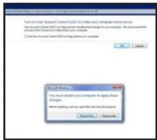
text_image
Windows 9.0.26 You must install your computer to apply these changes. Before adding, and any open file or cloud storage is needed.PICTURE 2-50
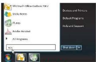
Windows 7
STEP 1. Open up the Start Menu (accessible by clicking on the Windows icon in the lower left of your screen.
STEP 2. Type "uac" into the search bar and hit ENTER. The User Account Control will open or you will be offered a link to click to open it.
STEP 3. Move slider to lowest setting and press OK.
text_image
Microsoft Office Outlook 2007 Sticky Notes ITunes Autumn Aircraft All Programs Add Edit Default Programs Help and Support Shut down +PICTURE 2-51
text_image
Select default rate Choose custom to be certified about: Changes to your computer Use default default rate partially, then change from default. It is not complete. Allow default rate to default default rate. Show default rate ■ Request the default rate to default default rate in the computer ■ Create default rate to default default rate. ■ Not applicable. Choose default and if you switch or replace default as we will choose default. ■ Include default rate to default default rate.PICTURE 2-52
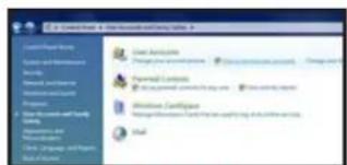
2.5 ADDITIONAL NETWORK SERVICES
Once you have connected the IP camera to a network and are able to access it from another network as well, you will need to obtain the Domain Name System (DNS) from your router and enter it into your camera to enable the camera to send out e-mail alerts. Optionally, you will also want to set up a Dynamic Domain Name Service (DDNS) to create an easy-to-use web address that you can use in place of the string of numbers making up the IP address when logging into the camera.
Entering these settings may be made within the Web Service or PSS software running on a computer connected to the same router as the camera. The method for obtaining the DNS is identical for either program. Both of these programs will be covered in full in their respective chapters following this one. However, it is generally easier to make the settings in Web Service, later accessing the camera using PSS since these settings must be made on a computer connected to the same router as the camera.
OBTAINING DNS INFO - MACINTOSH AND PC USERS
STEP 1. On a computer connected to the same router as your camera, open a web browser and enter the Gateway (Router's IP address) into the browser window's address bar to access your router.
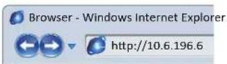
PICTURE 2-53
STEP 2. Locate your router's status window (may also be named "Information" or "Info", it will list the DNS number. You will only need to use the primary set of numbers - write it down for later use.
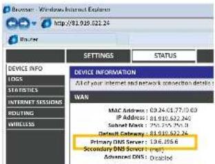
text_image
Browser - Windows Internet Explorer http://81.919.522.24 BLAYER SETTINGS STATUS DEVICE INFO LOGS STATISTICS INTERNET SESSIONS ROUTING WIRELESS DEVICE INFORMATION All of your internet network connection details WAR MAC Address: 09.24-01.77/03 IP Address: 81.919.522.240 Submit Next: 250.259.756.3 Default Gateway: 81.919.522.24 Primary DNS Server: 196.8066 Secondary DNS Server: empty Advanced DNS: DisabledPICTURE 2-54
MACINTOSH COMPUTERS
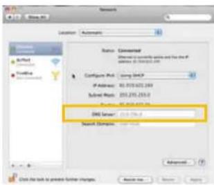
In addition to retrieving the DNS info from the router, Macintosh users can get it from the computer's Network window.
STEP 1. Click on the System Preferences icon at the bottom of the Macintosh's screen.

PICTURE 2-55
STEP 2. Click on the Network icon.

text_image
COS & DVUS Displays Energy Saver My Internet & Wireless MobileMe Network Bluetooth ShuPICTURE 2-56
STEP 3. Make sure that your network connection is highlighted in the list of connections to the right of the main part of the Network window and that its status reads "Connected."
The DNS server information will be shown. Write this down for use in the next section.
text_image
Network Location Automatics Status Elementary Address: 1000000000000000000000000000000000000000000000000000000000000000000000000000000000000000000000000 Configure IPv6: Using DHCP IPv6 Address: 85.973.622.2899 Submit IPv6: 255.275.255.2 DNS Server: 12.1.1.1.1 Search Elements: Advanced Click the link to protect further charges. Search No... Save... HelpPICTURE 2-57
ENTERING THE DNS INFORMATION INTO THE CAMERA
STEP 1. Open another browser window and enter the camera's Local IP address which you obtained in Section 2.3.
STEP 2. When the browser window has opened, you will be presented with a login screen for the Q-See Web Service. Since you're on the same network as the camera, you will want to select LAN from the options at the bottom of the screen.
text_image
QSEE® WEB SERVICE Username admin Password ****** Log 1 Log 2 Login CancelPICTURE 2-58
The default username and password are admin and admin. It is recommended for security reasons that you change the password once you have finished making your settings. Internet Explorer users may be asked to download an ActiveX plug-in from Q-See International, Ltd. Firefox and Chrome users may be asked to allow QuickTime to run. In these cases, you should allow the required plugins to operate. In some cases, you will be returned to the log in screen after the plugin has loaded. This is normal.
If you are able to log in with Internet Explorer, but are unable to view the video from the camera, please adjust the ActiveX settings as described at the end of Section 2.4.
STEP 3. Once the camera has opened. Click on the Network tab on the left and then on the TCP/IP option.
STEP 4. Enter the DNS number

text_image
Camera Network TCP/IP Connection PPPvE DDNS IP Filter SMTP(E-mail) UPnP Bonjour Event Record System Information TCP/IP Host Name IPC Ethernet Card Wire( DEFAULT ) Mode Static DHCP MAC Address 90 62 a9 08 s1 87 IP Version IPV4 IP Address 192 168 1 10 Subnet mask 255 255 255 0 Default Gateway 192 168 1 1 Preferred DNS Server 8 8 8 8 Alternate DNS Server 8 8 8 8 Enable ARP/IPing to set IP address service Default Refresh SavePICTURE 2-59
STEP 5. Click Save.
2.6 DYNAMIC DOMAIN NAME SERVICE (DDNS)
This is an optional step which allows you to take advantage of Dynamic Domain Name Service, or DDNS. Not to be confused with DNS above, DDNS allows you to enter a conventional web address when remotely logging into your Camera from outside of your network. It also allows you to avoid having to repeat Sections 2.3 when if your ISP reassigns IP addresses. Q-See offers DDNS service for free at www.MyQ-See.com and your IP camera is configured to accept account information from that site.
STEP 1. Open a browser window and go to www.MyQ-See.com
STEP 2. Register with the website and follow the instructions for creating a domain name. The website will display your pubic IP address and your domain name which will look like this: http://example.myq-See.com

text_image
NEW USER REGISTRATION EMAIL ADDRESS PASSWORD PASSWORD CONFIRM FIRST NAME LAST NAME SECURITY QUESTION. My first phone number ANSWER CONFIRM YOU'RE HUMAN 1241995 New Capsule Enter the text you see above Send ResetPICTURE 2-60
STEP 3. In your camera, click on the Network tab on the far left of the window.
STEP 4. Click on the DDNS option.
STEP 5. Check the Enable box and select MyQ-See.com in the DDNS server pull-down menu.
STEP 6. Enter your account information – including the user name and password that you used when creating your domain name.

text_image
Camera Network > E2MP > Commanden > PTPAC > DOS > IP Path > MSIPG (mat) > CFP > Bmpo Event DDHS Stainer Type: NO-IP-CCMS Server ID: dyspeta@msip.com Port: 50 (14-60538) Domain Name: none Universe: none Password: ****** Update Period: 5 (男性(1-500)) Default Network NonePICTURE 2-61
STEP 7. Click the Save button to preserve your settings.
USING WEB SERVICE
CHAPTER 3
The Web Service app allows you to access your camera with only a web browser. You connect with the camera by entering its address into the browser just like any other web page. As was explained in the previous chapter, if you are on the same network as the camera, then enter the local IP address shown in ConfigTool into a browser address window. When connecting to the camera from outside of its local network, you'll either use the Internet IP address obtained from CanYouSeeMe in Section 2.3 or the address you created using DDNS in Section 2.6. No matter whether you're accessing the camera locally or remotely, the operation will remain the same. You will not be able to access a camera directly connected to your NVR using the Web Service application.
Accessing the camera will bring up the login screen for the program. If you are connecting locally, the default video stream will be the larger Main Stream. Selecting WAN from the choices in the Login window will default to the lower-bandwidth Sub Stream. You can choose to switch between either stream once you have connected using the tabs above and to the left of the video display. The amount of activity on the network(s) can affect the streaming rate from the camera to your computer or mobile device.

text_image
QSee® WEB SERVICE Username: admin Password: ****** Login CancelPICTURE 3-1
3.1 LIVE VIEW
When you have logged in, you will see a live view from that camera. Live View is the default mode for the Web Service program. TCP is the default protocol. Use of the Multicast protocol for streaming requires it to be set up in your router.
natural_image
Exterior view of a modern office building (no signage)PICTURE 3-2
The main function of the Live View window is, of course, to display the video stream from the camera. There are additional settings available from the tabs located to the upper right of the video image. The operations of these will be covered on the following pages.
FUNCTION BUTTONS (PC ONLY)
PC users have three functions that can be performed while in Live View and the buttons for these are located immediately below the tabs in the upper right:
Digital Zoom - After clicking this button, click and drag on a section of the video image to enlarge it.
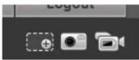
Digital Zoom
Snapshot Local
Record
PICTURE 3-3
Snapshot - Clicking this will take a still image of the current video feed.
Local Record - This will begin recording video to your computer's hard drive.
You will be able to set the location where video and still images are saved onto your computer's hard drive in the Camera option under the Setup tab.
3.2 SETUP
The options available in this tab are divided into several sections dedicated to the camera itself, the network connection, event monitoring, direct recording to an FTP server, system maintenance and history. Each of these sections will include one or more submenus to allow you complete control of your camera.
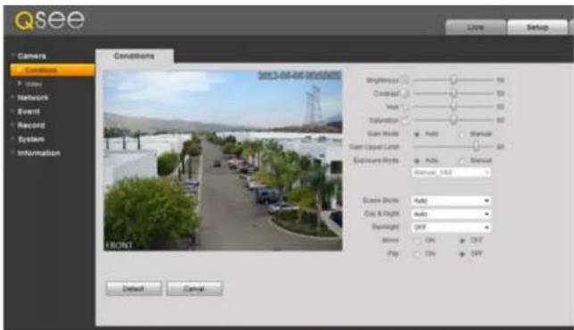
CAMERA
This is divided into two sub-menus - Conditions and Video. In Conditions, you can adjust the camera's settings to adjust for any lighting or environmental factors specific to its location for the best possible image.
text_image
Qsee Camera Conditions 2013-04-06 00:00:00:00 Brightness Sound Level Auto Stimulation Scan Mode Auto Manual Scan Level Label Auto Manual Exposure Mode Auto Manual Scope Mode Auto Clay & Flight Auto Drainlight OFF Mirror ON OUT Flip ON OFF Reset Cancel FinishPICTURE 3-4
The Brightness, Contrast, Hue and Saturation sliders can be moved to improve image clarity.
Gain - For cameras located in darker areas, Gain allows the camera to electronically compensate by making the image brighter. The trade off is a potential loss in image quality due to increased "noise" in the picture. You can allow the camera to adjust automatically or manually, with an adjustable upper limit to prevent the image from reaching a point where it is unusable due to excessive noise.
Exposure - this controls the amount of light reaching the camera's receptors. This allows the user to compensate for areas that are excessively lit resulting in overexposed images that have some detail areas "blown out." On a traditional camera, this feature would be controlled by opening or closing the camera's iris. On an IP camera, this is controlled electronically. You can "lock" the exposure level to a specific setting by selecting Manual and adjusting it from the pull-down menu.
Scene Mode - This allows the camera to compensate for sunlight versus moon light. This is done by adjusting the red and blue light levels. This can be done automatically, or is fully customizable by the user. The mode can also be disabled or set to permanently utilize only a single mode.
VIDEO
The Video sub-menu contains four tabs controlling how video is streamed from the NVR, the camera's built-in snapshot feature, on-screen displays and, on PCs the file path to save locally recorded video and snapshots.

text_image
Qsee Video Stragulink Overlay Paths Live Setup Camera Conditions Index Network Event Record System Information Wave Stream Rate Stream Code Stream Type: General Route Name: n20a Resolution: 120* (120*720) Frames label (FPS): 30 80 Rate Type: C964 Reference Settings: 2500-81444000 80 Rate: 4000 1 Frame Interval: 60 (25-195) ✓ Underwrite Settings Underwrite Character: DigitalCTV Rate Stream Route Stream Type: General Route Name: n20a Resolution: D1 (75*485) Frame label (FPS): 60 80 Rate Type: 1600 Speed: 4 Reference Bit Rate: 356 (356*47) 80 Rate: 640 1/8/8/8/8: 60 (50-100) Default Refresh SavePICTURE 3-5
The settings available within the Video tab are similar to the options available in the Record Setting menu which was covered in Section 2.2. However, these settings only apply to the camera and not the NVR. If the Internet connection is poor either at the camera's location or with the monitoring PC or device, then the settings can be lowered to improve the video transfer. For example: a bitrate of 4096 requires an upload speed of 4mbps.
The Snapshot tab allows you to set the resolution, quality and frequency of snapshots captured by the camera. These are separate from the snapshots captured by the NVR using this camera.
You can change the camera's name, create a privacy mask and enable/disable the on-screen display of the camera's name and time in the Overlay tab. Your NVR is configured not to display the channel title info on its screen, but you may change that setting in the Overlay setting within the
Record Setting menu (see Section 4.3 of the User Manual).
You may set up to four masked areas in the camera's display. These are separate from those made in your system and cannot be overridden by the masks made in the NVR.
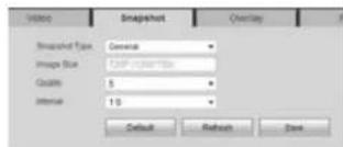
text_image
Video Snapshot Overlay Snapshot Type: General Image Size: 1200 x 100 mm Quality: 5 Interval: 1.5 Default Refresh SavePICTURE 3-6
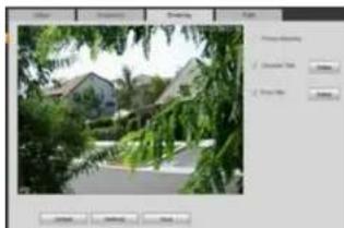
natural_image
Street view of residential buildings with greenery, no visible text or symbolsPICTURE 3-7
Path allows you to select the location on your PC's hard drive where video and snapshots will be saved when the appropriate icon is selected in Live View.
3.3 NETWORK
The settings available in this menu govern how the camera connects to the outside world. Many of these features are exactly like the same functions on the NVR.
TCP/IP
Like your NVR - and every other device connected to your network router - the IP camera has an Internet Protocol, or IP address. As a general rule, this should not be changed in order to avoid future connection problems. However, if you wish to establish a static IP address, it is done here.

text_image
Camera Network TCP/IP Connection PPPoE DDNS IP-Filter SMTP(E-mail) UPnP Bonjour Event Record System Information TCP/IP Host Name IPC Ethernet Card Wire( DEFAULT ) Mode Static DHCP MAC Address 90 02 x9 08 x1 87 IP Version IPV4 IP Address 192 168 1 10 Subnet mask 255 256 255 8 Default Gateway 192 168 1 1 Preferred DNS Server 8 8 8 8 Alternate DNS Server 8 8 8 8 Enable ARP/Ping to set IP address service Default Refresh SavePICTURE 3-8
STATIC IP ADDRESS
All routers currently on the market have DHCP functionality. This means that the router will assign a newly-connected network device a random IP address that is not currently in use by another device on your internal network. If this feature is enabled in the router as well as selected within this window, the camera will automatically receive an IP address.
The reason for converting to a static IP address is to ensure that the camera's IP address stays unchanged in case of a power loss by the router. With the exception of 2Wire brand routers, when a router or networked device raboots due to a power loss or other issue, the addresses will change and the port forwarding configuration will no longer work. For that reason, unless you have a 2Wire router, we recommend changing your NVR's network setting to a fixed, or "static" IP address which will not change.
To convert to a Static IP address, all you need to do is check that option and then click Save.
CONNECTION
The fields in this window allow you to set the maximum number of simultaneous user connections, as well as showing which TCP port was forwarded.
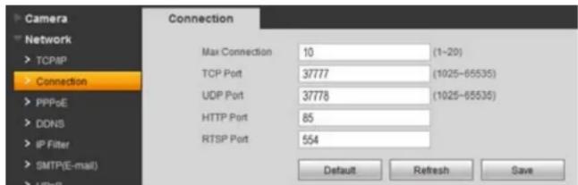
text_image
Camera Network TCP/IP Connection PPPoE DDNS IP Filter SMTP(E-mail) HTTP Max Connection 10 (1-20) TCP Port 37777 (1025-65535) UDP Port 37778 (1025-65535) HTTP Port 85 RTSP Port 554 Default Refresh SavePICTURE 3-9
PPPOE
If you are going to attach the NVR directly to a DSL or cable modem instead of to a router then select the PPPOE option in the Network options. Before you proceed, you will need to contact your ISP to obtain your User Name and Password. You will not have to worry about Static IP (previous section).
DDNS
This was covered in Section 2.6.
IP FILTER
Using this window, you can create a "white list" of trusted IP addresses for users who are allowed access to this camera. Any IP address that is not listed will not be allowed to access this camera. If you will only be accessing this camera through the NVR, then you should enter the NVR's IP address as an extra layer of security. However, it is important to add the IP address that you are currently accessing the camera from to ensure that you are able to continue to make your settings without getting "locked out" of the camera. This address can be removed once you have completed configuring the camera.
SMTP (E-MAIL)
The camera can send out its own e-mail alerts - with snapshot attachments. If the camera is connected remotely to an NVR, these e-mails will be in addition to those that the NVR creates. The camera's e-mail address should therefore be different than that used for the NVR to avoid confusion.

NOTE! Depending upon your settings, the system can generate a lot of e-mail alerts. For that reason, we recommend setting up a dedicated e-mail address specifically for the system to send alert notices. If you do not have your own e-mail system (such as a corporate mail server) you should consider using a free e-mail provider. However, because many free e-mail services allow only a part of e-mail traffic we specifically recommend using Google's Gmail service with it. Similarly, you will want the alert e-mails to go to a different account than the them. This will ease your management of these alerts.
SMTP Server – This the SMTP server IP name
Port – This is the port your mail provider uses
User Name and Password – These are for the sending e-mail address and were set up when you created the e-mail account.
Title – This is the subject line of e-mails generated by this NVR.
Receiver – This is the recipient e-mail account.
Attachment – This allows the e-mail to include one or more snapshots as attachments
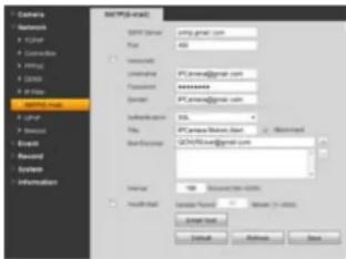
text_image
Ctemers Networks X2014 Connects X1954 X2006 X2007 X2008 X2009 X2010 X2011 X2012 X2013 X2014 X2015 X2016 X2017 X2018 X2019 X2020 X2021 X2022 X2023 X2024 X2025 X2026 X2027 X2028 X2029 X2030 X2031 X2032 X2033 X2034 X2035 X2036 X2037 X2038 X2039 X2040 X2041 X2042 X2043 X2044 X2045 X2046 X2047 X2048 X2049 X2050 X2051 X2052 X2053 X2054 X2055 X2056 X2057 X2058 X2059 X2060 X2061 X2062 X2063 X2064 X2065 X2066 X2067 X2068 X2069 X2070 X2071 X2072 X2073 X2074 X2075 X2076 X2077 X2078 X2079 X2080 X2081 X2082 X2083 X2084 X2085 X2086 X2087 X2088 X2089 X2090 X2091 X2092 X2093 X2094 X2095 X2096 X2097 X2098 X2099 X3000PICTURE 3-10
SSL Enable – The system supports SSL encryption when this is enabled.
Interval - This adjusts the amount of time that will pass before the NVR sends out another e-mail. The interval can be set from 0 seconds to ten hours (3600 seconds). If you are getting too many e-mails, you may wish to increase the length of the interval. Using this feature also helps prevent overloading your outgoing e-mail server.
UPNP (UNIVERSAL PLUG 'N' PLAY)
As described in Section 2.4, UPnP allows networked devices to communicate with each other. UPnP, like DHCP, allows the router to assign the camera an IP address on its network, and will automatically forward the ports for outside communication. In addition to the HTTP (port 85) and TCP (port 37777) communications protocols, UDP and RTSP allow the camera to stream data and communicate with other devices.
BONJOUR
Bonjour is Apple Inc.'s version of UPnP to enable easy network connectivity.
3.4 EVENT
Like your NVR, your IP camera can detect motion events and when it is being blocked or masked. You can configure these features on your camera in the same manner as on your NVR and alerts can be e-mailed and/or alarms triggered. Using these features on the IP Camera would not interfere with the operations on the NVR and some users prefer the duplication of event detection as a backup in case the NVR is affected.
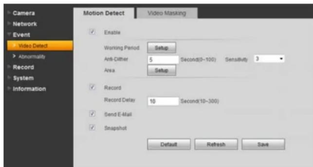
text_image
Camera Network Event Video Detect Abnormality Record System Information Motion Detect Video Masking Enable Working Period Setup Anti-Dither 5 Second(0~100) Sensitivity Area Setup Record Record Delay 10 Second(10~300) Send E-Mail Snapshot Default Refresh SavePICTURE 3-11
The operation and setup of these event monitoring is identical to that on the NVR itself. See Section 3.7 of the User Manual for full explanations.
MOTION DETECTION
Clicking on Setup next to Working Period will open up a schedule allowing you to set the periods when the camera will actively detect motion events. You can set six periods each day for the camera to be "on alert" using the start and stop times at the bottom. Click Save to preserve your changes and they will appear on the schedule when you next open the window.
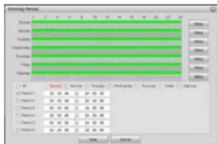
text_image
Recording Track Track Track Track Track Track Track Track Track Track Track Track Track Track Track Track Track Track Track Track Track Track Track Track Track Track Track Track Track Track Track Track Track Track Track Track Track Track Track Track Track Track Track Track Track Track Track Track Track Track Speed Speed Speed Speed Speed Speed Speed Speed Speed Speed Speed Speed Speed Speed Speed Speed Speed Speed Speed Speed Speed Speed Speed Speed Speed Speed Speed Speed Speed Speed Speed Speed Speed Speed Speed Speed Speed Speed Speed Speed Speed Speed Speed Speed Speed Speed Speed Speed Speed SpeedPICTURE 3-12
You can enable a motion alert to trigger several one or more events - video recording, e-mail alerts and snapshot images. Videos and snapshots are sent to an FTP site - which must be set up by the user. Some camera models allow the insertion of a Micro SD flash memory chip which can be used to store these images "onboard" the camera for retrieval using the PSS software. Video recording is controlled by the Recording Schedule (see following pages) which overrides the settings here. If the camera is set to record on motion detection, those recordings will only take place during the time period(s) configured in the Recording Schedule.
Anti-Dither - is the amount of time that the camera will delay before beginning the alarm response. If the motion isn't detected again during the delay period, the camera will not treat it as an event.
Sensitivity - You can adjust the camera's sensitivity to motion to minimize false alarms caused by environmental factors such as insects.
Record Delay - This is the amount of time beyond the event that the camera will continue to record.
In addition to triggering recording, you can also have the camera take a snapshot and send an alert e-mail.
Click on the Setup button next to Area to turn off motion detection in certain areas, such as roads, a flag or trees that move in the wind to avoid false alarms. Clicking on a square in the grid, or clicking and dragging across multiple areas will remove the blue mask and deactivate motion detection in that area.
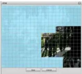
natural_image
Two small outdoor scenes on a grid background, one with trees and the other with buildings (no visible text or symbols)PICTURE 3-13
VIDEO MASKING
If the camera detects that it is being blocked or covered, it can be configured to record, send an e-mail and/or take a snapshot of what it sees. You can also set up a schedule so that it will not be active during a regularly scheduled period when it might be blocked by a door, for example.
DISCONNECTION
If the IP Camera detects that it no longer has a network connection, and if it has an SD flash memory chip installed, it can record video to the chip for later recovery through the PSS software.
IP CONFLICT
Whether in DHCP or UPnP, the router will automatically assign IP addresses to devices on its network. If someone on the network manually changes the IP address of a connected device to an address identical to that of the IP camera, this can cause difficulty in accessing the camera remotely. You can enable the camera to begin recording if this occurs.
3.5 RECORD
If you have enabled the record function for this camera elsewhere in the Web Service program, you will need to set when those recordings will occur using the Record Schedule tab. In addition, you will need to configure the destination for those files along with the duration and quality of the recorded files.
Videos will be recorded in the .day format and will require the use of the included video player software to review and convert to a different format.
RECORD SCHEDULE
The camera is configured to allow event recording all day and every day. To change these settings, click on the Setup button to the right of the date you wish to schedule.

text_image
Camera Network Event Record Schedule Destination Record Control System Information Record Schedule Annotated Schedule 8 2 4 6 8 10 12 14 16 18 20 22 24 Sunday Monday Tuesday Wednesday Thursday Friday Saturday Default Refresh Save Setup Setup Setup Setup Setup SetupPICTURE 3-14
The pop-up Setup window will open allowing you to set up to six periods within a day during which recording will be enabled.
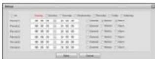
PICTURE 3-15
SNAPSHOT SCHEDULE
This is exactly like the Recording Schedule.
FILE DESTINATION PATH
Unlike an NVR, the camera does not contain a hard drive on which to record its files. The default method is to use an FTP (File Transfer Protocol) site to store the recorded files for later access. An FTP site is the equivalent of an Internet-accessible hard drive. There are both free and commercial sources for FTP hosting available through the web.
Some camera models allow the installation of a Micro SD card within the camera. Due to the nature of security cameras, these chips are not easily accessible once the camera has been installed, but the files may be retrieved using the PSS software. If you are using a camera with an installed Micro SD card, an extra tab (not shown) will appear allowing you to make additional configurations.

text_image
Camera Network Event Residual Systematic Information Photo Sensor Data Control System Information Event Type Motion-Dated Camera FIP C C C C C C C C CPICTURE 3-16
Both recorded video and snapshots can be saved to the FTP site. You can allow all types of events to be saved, or choose only Timer (scheduled recordings), Motion Detection or Alarm events to be saved to the FTP.
Use the FTP tab to direct the camera where to save the files. You will also need to enter the user name and password that you normally use when you log into the site yourself, or you can create a specific user account for this camera. The Remote Directory is the folder into which the files will be saved.

text_image
Path PTP Create Name: 196 208 18 65 Port: 49 (3-600/3F) UserName: User Password: ******** Remote Direction: CameraDocx Default Refresh SavePICTURE 3-17
RECORD CONTROL
This tab allows you to set the maximum length of the recorded video, along with amount of pre-event video is added to the file. Like the NVR, you can have the camera overwrite old files when the storage area is exceeded, or it can stop recording until the files are manually deleted.
Additionally, you may choose to record larger main stream of video, or the smaller - and lower quality - sub stream.
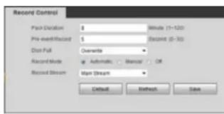
text_image
Record Control Pair Dislocation 0 Minutes (1-120) Pre-identification 5 Record (0-30) Dist Full Downtime Record Mode Automatic Baccal OR Record Stream Up/Down Default Refresh SavePICTURE 3-18
3.6 SYSTEM
This submenu is where the user can make changes to the camera itself, including setting local time, configuring user accounts, upgrade the firmware and reset all values to their default settings.
GENERAL
You can change the camera's device name here, which will make it easier to pick out in the Remote Device menu when adding it to your NVR.
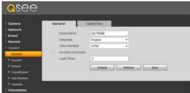
text_image
Qsee Camera Network Event Record System General Account Default ImportExport Auto Maintain Upgrade Information General Date&Time: Device Name QC7002B Language English Video Standard NTSC Account Lock Enable Login Times 3 Default Refresh SavePICTURE 3-19
English is the only language currently available and you can choose the video standard - NTSC (North America and most of South America) or PAL (Europe), but this won't generally make a difference when monitoring the camera through the Web Service program or the NVR.
Account Lock Enable is disabled by default. Enabling this feature will lock the camera from remote access - either by the NVR or through the Web Service - app if the wrong user names or passwords are entered the selected number of times. If the camera is locked out, it will need to be physically reset using the Reset button on or in the camera (depending on model).
DATE & TIME
The date and time can be set locally for the camera and it can synchronize with a time server and keep track of Daylight Savings Time just like the NVR.
The SyncPC button will set the time to that of the computer which you are using to access it. Keep in mind, that settings on the NVR can override this and synchronize the time with itself as described in Section 4.3 of the
User Manual.

text_image
General Date: 00 Dial-Formal Time Format Time Zone Current Time 2012 07 - 24 11 34 00 Dial Engine Dial Type Start Time Begin Time Sequence with VTP VTP Status: Port Update Period 26 (Month-NO) Default Refresh SavePICTURE 3-20
ACCOUNT
This window shows all the available user accounts. There are three pre-configured accounts available with different authority levels. The admin account has full privileges to view or change the camera's settings, while the 666666 user account can only view the camera's live feed. The Authority List at the bottom of the window shows what each account may do with the camera.
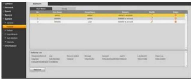
text_image
Users Name Status Gender Access Help Default User Name Name Gender Access Access Help Default User Name Name Gender Access Access Help Default User Name Name Gender Access Access Help Default User Name Name Gender Access Access Help Default User Name Name Gender Access Access Help Default User Name Name Gender Access Access Help Default User Name Name Gender Access Access Help Default User NamePICTURE 3-21
You may edit, add or delete accounts, with the exception of the admin account. It is strongly recommended that you change the passwords from their default settings. A malicious user would have to discover the camera's IP address in order to access it in the first place, but changing the password prevents unauthorized tampering.
DEFAULT
Clicking this button will reset everything to the factory default settings.
IMPORT/EXPORT
You can back up your camera's configuration settings onto a computer to later import back into the camera if needed.
AUTO MAINTAIN
This allows you to have the camera reboot on schedule to improve performance - much like a computer. You can set the time and day of the week when this reboot will take place.
UPGRADE
Q-See releases firmware updates from time to time to address known issues, to address specific issues or to add functionality. You can download the firmware update file to the computer you are using to access the camera and then use the Browse button to navigate to the file before clicking on Upgrade.
INFORMATION
This window shows both the current version of the software along with the camera's serial number in addition to an event log that the camera maintains.
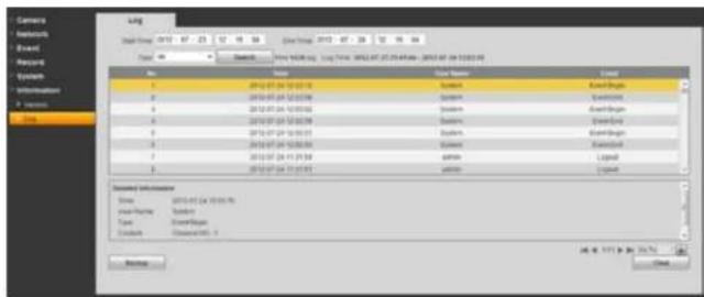
text_image
Camera Networks Rapid Forest Systems System10000000000000000000000000000000000000000000000000000000000000000000000000000000000000000000000000 Name: AutoCAD System: AutoCAD System1. AutoCAD System2. AutoCAD System3. AutoCAD System4. AutoCAD System5. AutoCAD System6. AutoCAD System7. AutoCAD System8. AutoCAD System9. AutoCAD System10. AutoCAD System11. AutoCAD System12. AutoCAD System13. AutoCAD System14. AutoCAD System15. AutoCAD System16. AutoCAD System17. AutoCAD System18. AutoCAD System19. AutoCAD System20. AutoCAD System21. AutoCAD System22. AutoCAD System23. AutoCAD System24. AutoCAD System25. AutoCAD System26. AutoCAD System27. AutoCAD System28. AutoCAD System29. AutoCAD System30. AutoCAD System31. AutoCAD System32. AutoCAD System33. AutoCAD System34. AutoCAD System35. AutoCAD System36. AutoCAD System37. AutoCAD System38. AutoCAD System39. AutoCAD System40. AutoCAD System41. AutoCAD System42. AutoCAD System43. AutoCAD System44. AutoCAD System45. AutoCAD System46. AutoCAD System47. AutoCAD System48. AutoCAD System49. AutoCAD System50. AutoCAD System51. AutoCAD System52. AutoCAD System53. AutoCAD System54. AutoCAD System55. AutoCAD System56. AutoCAD System57. AutoCAD System58. AutoCAD System59. AutoCAD System60. AutoCAD System61. AutoCAD System62. AutoCAD System63. AutoCAD System64. AutoCAD System65. AutoCAD System66. AutoCAD System67. AutoCAD System68. AutoCAD System69. AutoCAD System70. AutoCAD System71. AutoCAD System72. AutoCAD System73. AutoCAD System74. AutoCAD System75. AutoCAD System76. AutoCAD System77. AutoCAD System78. AutoCAD System79. AutoCAD System80. AutoCAD System81. AutoCAD System82. AutoCAD System83. AutoCAD System84. AutoCAD System85. AutoCAD System86. AutoCAD System87. AutoCAD System88. AutoCAD System89. AutoCAD System90. AutoCAD System91. AutoCAD System92. AutoCAD System93. AutoCAD System94. AutoCAD System95. AutoCAD System96. AutoCAD System97. AutoCAD System98. AutoCAD System99. AutoCADPICTURE 3-22
Clicking on an event will bring up detailed information in the bottom window, including the nature of the event.
You can back up the logs to your computer or clear the log file.
ALARM
The Alarm window contains a log of all events, which can be searched by selecting the Alarm Type of interest.

text_image
Qsee View Default Name Locks Name Type Show Case Show Options Show Type Show Case Show Options Show Type Show Case Show Options Show Type Show Case Show Options Show Type Show Case Show Options Show Type Show Case Show Options Show Type Show Case Show Options Show Type Show Case Show Options Show Type Show Case Show Options Show Type Show Case Show Options Show Type Show Case Show Options Show Type Show Case Show Options Show Types Show Case Show Options Show Type Show Case Show Options Show Type Show Case Show Options Show Type Show Case Show Options Show Type Show Case Show Options Show Type Show Case Show Options Show Type Show Case Show Options Show Type Show Case Show Options Show Type Show Case Show Options Show Type Show Case Show Options Show Type Show Case Show Options Show TypePICTURE 3-23
You can also have the camera alert you of any events that occur while you're monitoring it. Select an audio file from your computer to serve as the alarm tone.
LOGOUT
Clicking this tab will log you out of the camera and return you to the Login window.
PRO SURVEILLANCE SOFTWARE CHAPTER 4
4.1 INSTALLING PSS
Unlike Web Service, which is a self-installing application that runs in the web browser, Pro Surveillance Software is a stand-alone program that needs to be installed onto a computer. This software is included on the disk that comes with your camera. PC users can install the software directly from the interactive CD menu. Macintosh users will need to open the Software folder on the disk.
The file is also available for free download on Q-See.com, but you will need to download an extraction program to uncompress the file for installation. One such extraction program can be downloaded for free at at http://rarlabs.com/download.htm
INSTALLING PSS ON A PC
Please note that some PC users may find that they have to adjust their UAC and ActiveX settings as described in Section 2.4 in order to use PSS without errors.
STEP 1. Double click on the Pro Surveillance System icon in the PSS for Windows folder to extract and install the program.

text_image
Computer Linear (R) PSS for Windows Share with Burn New Folder Edit Faces Pro Surveillance System PSS Manual Setup EndsPICTURE 4-1
STEP 2. A shortcut icon for the PSS application should appear on the desktop. If you do not see it, the program can be found in the Programs folder.
STEP 3. Double click on the icon to run the program.

PSS
PICTURE 4-2
Please go to Section 3.2 for instructions on controlling your NVR using PSS.
INSTALLING PSS ON A MAC
Mac users will not have to turn off UAC or enable ActiveX to access their camera from their computer. However, you will need to install the latest version of the XQuartz application. It is available for free from CNet.com at:
http://download.cnet.com/XQuartz/3000-2094\_4-10912185.html
You will also need to install and run the PSS (Pro Surveillance Software) program included on the CD that was packaged along with your NVR. The file is also available for free download on Q-See.com, but you will need to download an extraction program, UnrarX to be able to use the application. It is available for free at http://www.unrarx.com
PSS will automatically launch and run inside of XQuartz and will show up as "X11" in the application bar at the top of the screen.
STEP 1. Double click on the PSSSetup. pkg icon in the PSS for Mac folder to extract and install the program.
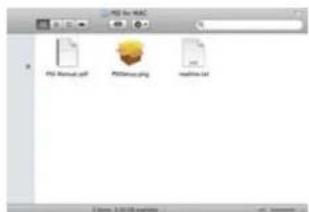
text_image
PDF for MABC PDF Manual.pdf PDFBox.png computer.txtPICTURE 4-3
STEP 2. A shortcut icon for the PSS application should appear on the desktop. If you do not see it, the program can be found in the Applications folder.
STEP 3. Double click on the icon to run the program.

PSS
PICTURE 4-4
4.2 USING PRO SURVEILLANCE SOFTWARE (PSS)
The included Pro Surveillance Software allows Mac and PC users a method to remotely monitor their NVR that is not browser-dependent. PSS is compatible with Windows XP, Vista and 7 as well as Mac OSX 10.6 and 10.7. The software interface is identical across computing platforms so both PC and Mac use is described. An expanded manual for the software is included on the CD that came with the camera and is also located in the same folder as the program on your computer.
After installing the software (covered in Section 3.1), double click on the PSS icon to launch the program.
Enter the User Name and Password in the appropriate fields. The default user name and password are admin and admin.

PICTURE 4-5
The areas of the PSS display screen each have their own functions:

text_image
PRO SURVEILLANCE SYSTEM User Name: ### Password: ****** Save Password Logit ExitPICTURE 4-6

IMPORTANT! We strongly recommend that you modify your password after you first log in for improved security.
For instructions on remotely controlling your NVR using PSS, please go to the next section.
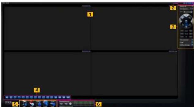
text_image
Screenshot of a video editing software interface with numbered UI elements and playback controlsPICTURE 4-7
| Item # Area Function | |
| 1 Real-Time Monitor Live viewing of selected channels plus playback of recorded video. | |
| 2 Window Controls Close, minimize, lock or switch the program's window. | |
| 3 Tool Bar Controls include: Device List, PTZ Direction, PTZ Advanced, Tool and Setting Manager. | |
| 4 Image View Options Controls for number of channels viewable at once plus other options | |
| 5 Function Buttons Controls and settings for various NVR functions. | |
| 6 NVR Status Shows the status of the NVR, the hard drive and the cameras |
| Item # Area Function | |
| 1 Real-Time Monitor Live viewing of selected channels plus playback of recorded video. | |
| 2 Window Controls Close, minimize, lock or switch the program's window. | |
| 3 Tool Bar Controls include: Device List, PTZ Direction, PTZ Advanced, Tool and Setting Manager. | |
| 4 Image View Options Controls for number of channels viewable at once plus other options | |
| 5 Function Buttons Controls and settings for various NVR functions. | |
| 6 NVR Status Shows the status of the NVR, the hard drive and the cameras. |
CONNECTING TO THE CAMERA
Before you can begin to monitor the camera, you must first connect to it.
STEP 1. Click on the blue Full Menu icon to the right of the Setting Manage button in the Tool Bar on the right side of the display.
STEP 2. Select Device Manage to open the Device Manage window.
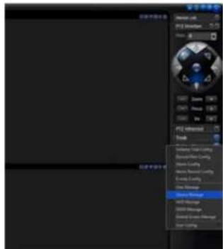
STEP 3. Click the Add button and enter the camera's IP address (Section
2.3) or DDNS address (obtained in Section 2.5), port number, your user name and password (which are the same that you use to log into the camera directly). You can also give the camera an identifying name and you can add a note in the Description field.
You can also add other types of devices such as a network backup storage drive using this window. Leave Login Type at its default Network Type TCP setting.

text_image
User Settings Parameters Name: 10000000000000000000000000000000000000000000000000000000000000000000000000000000000000000000000000000 Name: 12345678 Description: Name: 12345678 Description: Name: 12345678 Description: Name: 12345678 Description: Name: 12345678 Description: Name: 12345678 Description: Name: 12345678 Description: Name: 12345678 Description: Name: Name: Name: Name: Name: Name: Name: Name: Name: Name: Name: Name: Name: Name: Name: Name: Name: Name: Name: Name: Name: Name: Name: Name: Name: Name: Name: Name: Name: Name: Name: Name: Name: Name: Name: Name: Name: Name: Name: Name: Name: Name: Name: Name: Name: Name: Name: Name: Name: Name: NonePICTURE 4-9
You can return to this window to update your passwords, add or remove other devices and make network access changes if need be.
A prompt will pop up at the bottom right of the screen to indicate that the camera has been added to the program.

PICTURE 4-10
Step 4. The camera will now appear in the Device List at the top of the Tool Bar. Click on the device name to expand the listing and you can add cameras.

text_image
Device List DVR IP Camera 10.15.5.179 CAM 1 Alarm Or NVD SNVDPICTURE 4-11
STEP 5. Choose the screen view format you wish to use and then click on the segment of the screen where you want to place the first camera. Then, click on the camera number in the Device List to add that camera. Repeat by selecting a new area. The area highlighted in green is the current camera view. Clicking on a camera icon while a camera view is highlighted will replace that view with the channel you just selected.
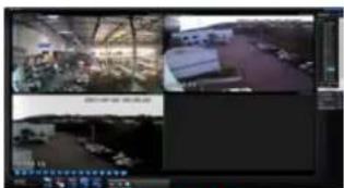
text_image
Screenshot of a surveillance camera interface with multiple video and image panels showing industrial equipment and dataPICTURE 4-12
REAL-TIME MONITOR
Live monitoring and recorded video playback takes place in the Real-Time Monitor section of the window. The number of screens being viewed at once is set with the Image View Options at the bottom of the screen (described below), but at any time, you can double-click on any channel in multi-view mode to make it a single-screen view. Double-clicking on the screen will return it to its place in the multi-view display.
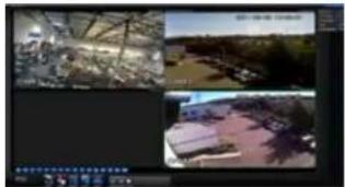
natural_image
Four-panel video editing interface showing outdoor scenes with trees, buildings, and a landscape (no visible text or symbols)PICTURE 4-13
At the top of each channel's video display, there is a set of data and a set of six function buttons.

PICTURE 4-14
The data in the upper left shows the NVR's name, the stream rate for that channel as well as its frame rate.
The function buttons allow you to perform operations with and within the display. Each button will only affect the channel it is attached to. Other channels will not be affected.
| Symbol Button Function | ||
| Digital Zoom | Select this button (it will highlight in white) and then click and drag within the video image to zoom in on that section. Clicking on the button again will return you to the original view. | |
| Multi-Screen/ Single Screen View | This will switch between a multi-screen or single screen view of that video. | |
| Local Record | When this button is selected, you will begin recording it to your computer | |
| Snapshot | This will take still images of the video which will be saved according to your settings in Pic Path | |
| Audio | Turns audio on or off if this channel has audio connected to it. This does not have any relationship to the computer's audio | |
| Close Video | Ends the video display for that channel | |
IMAGE VIEW OPTIONS
This row of buttons along the bottom of the Real-Time Monitor area allow you to set how you will view the video feeds in addition to how many screens will be displayed simultaneously. Some settings will display more channels than a single NVR can connect to, but if you are controlling multiple QC-Series NVRs and cameras using PSS you will be able to display the signals from multiple remote devices simultaneously. When you do not have as many cameras as channels displayed, the empty channels will remain grayed out and the area above each screen where the device name, stream and frame rate would be displayed will remain blank instead.
| HD | ||||||||||||||||||||||||||||||||||||||||||||||||||||||||||||||||||||||||||||||||||||||||||||||||||||
| 25 | 36 | 49 | 64 |
PICTURE 4-15
The first three buttons in the row deal with image quality and size, while the remaining buttons will configure the display to show 1-64 images.
| Symbol Button Function | ||
| Image Quality This raises or lowers the quality of the image | ||
| Latency/Fluency Allows you to prioritize image quality versus smoothness of the video | ||
| Full Screen Selecting this will expand the entire display to fill the full screen, hiding all the controls. | ||
In the case of the Image Quality and Latency/Fluency buttons, only the channel highlighted in green will be affected.
In multi-screen mode, a channel can be clicked and dragged to another location. This is useful in those modes where one or two screens are larger than the others. The channel being replaced will move to the old location of the one that was moved.
Double clicking on a channel will bring that to single screen mode. Double clicking on it again will return to the previous multi-channel format.
WINDOW CONTROLS
The buttons at the top right corner of the PSS display window allow you to lock the display, offer shortcuts to certain functions and let you toggle normal window operations such as full-screen, minimize and close the display.

PICTURE 4-16
| Symbol Button Function/Options | |
 | Lock Locks the application. You will have to re-enter your password to resume control of the program. |
 | Full Menu Access Password settings, Log Out and shortcuts to function and menu buttons. |
 | Minimize Hides the PSS display while keeping PSS running. This will also cause the PSS icon to disappear from your Windows application "fray" at the bottom of your screen in order to hide access to the program. It will be located in the "Hidden Icons" section of the tray until you select it at which time PSS will maximize. |
 | Switch Switch to and from full-screen display |
 | Close Closes PSS. You will have to confirm the closure by entering your password. |
For expanded descriptions on the operations and functions of these buttons, please see the PSS manual located on the installation disk or on your computer - located with the PSS software itself.
TOOL BAR
This section of the PSS display contains many of the controls for on-screen viewing.
Device List - This is where you access the camera's you wish to view and control from the software. This function was covered earlier in this section under "Connecting to the NVR."
This is also where you access the NVR itself to change settings.
Step 1. In Device List, right click on the NVR you wish to access.
Step 2. Click on Advanced in the menu.
Step 3. Click on Device Config in the submenu.
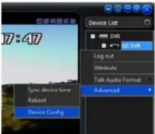
text_image
17:47 Sync device time Reboot Device Config Device List DVR Log out Attribute Talk Audio Format AdvancedPICTURE 4-17
The Device Configuration menu gives you access to the Setting and Advanced menus on the NVR. You can make changes or add new settings in the same manner as if you were at the NVR itself. These operations are covered in Chapters 3, 4 and 5 of the User Manual.

text_image
Device Config Control Panel Query System Info VERSION HDD INFO LOG System Config GENERAL ENCODE SCHEDULE NETWORK DETECT DEFAULT/BACKUP ADVANCED HDD MANAGEMENT ABNORMALITY Record ACCOUNT SNAPSHOT AUTO MAINTENANC ADDITIONAL FUNCTION ATMPOS Auto Register IP Filter Talk Encode Item Status S.N PA0FF0400056 Video In/Out 4/1 Audio In/Out 2/1 Alarm In/Out 0/5 Ethernet Post 1 RS232 0 Bao Version 2.60K Q530.0 Build 2011-1-27PICTURE 4-18
PTZ Direction - Your camera must have PTZ functionality to use. It operates in the same manner as the PTZ controls on the a NVR as shown in the User Manual.
By clicking on the padlock icon at the top of this menu, you can separate this control from the rest of the display and position it anywhere on the screen. Clicking on the padlock returns it to its position in the main display.
PTZ Advanced - Like the main PTZ controls, this control panel replicates the operations found on a NVR. The user can activate presets, tours and patterns plus other features that are dependent upon the model of PTZ camera in use.

text_image
PTZ Direction Step: 4 — Zoom + — Focus + — Ins +PICTURE 4-19

text_image
PTZ Advanced Flip Aux Auto scan Auto pan Light Viper Preset 1 Go preset Setup Auto tour 1 Run Setup Pattern 1 Run SetupPICTURE 4-20
Tool - This menu gives you access to several functions and features:
Begin Recording Plan - Activates a pre-defined local recording plan.
NVD Control - Opens a proprietary video playback and decoding window.
Health Report - Shows the status of all connected devices.
Log Query - Shows records of when PSS was accessed and by who as well as any system failures.
Alarm Video - Opens a pop-up window displaying selected channels when an alarm is activated.
Alarm Output - Open or close all alarm outputs.
Color Config - Adjust hue, balance, contrast and saturation.
Volume - Control for any connected microphones.
Setting Manage - Clicking on the blue icon on this lab reveals additional settings which parallel their counterparts on the camera itself. However, these settings only apply to local recording from the camera onto the computer and do not override the settings on the camera.
Of note are three additional features - E-map Configuration, User Management and User Configuration. The first allows you to upload an image of a map which you can use to mark the location of cameras. This is utilized in the E-Map tab at the bottom of the screen. User Management allows you to define what PSS-specific rights users have and you can import or export those settings for use on other computers running PSS through User Configuration.
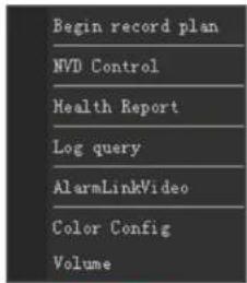
text_image
Begin record plan NVD Control Health Report Log query AlarmLinkVideo Color Config VolumePICTURE 4-21
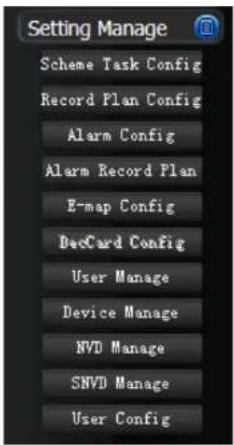
text_image
Setting Manage Scheme Task Config Record Plan Config Alarm Config Alarm Record Plan E-map Config DecCard Config User Manage Device Manage NVD Manage SNVD Manage User ConfigPICTURE 4-22
FUNCTION BUTTONS
The five function buttons: Task, Alarm, Playback, E-map and Configuration, are located at the bottom of the display.

text_image
Task Alarm Playback E-map ConfigPICTURE 4-23
Task
This allows you to run a pre-configured operation - set in the Scheme Task Configuration button under the Setting Management menu in the Tool Bar.
Alarm
This log shows all the events recorded by the NVR when motion is detected or an external alarm triggers recording.
| Gene Symbol | ||||||
| Gene name | Description | Position 1 | Position 2 | Position 3 | Sequence 1 | Sequence 2 |
| 10 | Tyr | Unknown | ||||
| 101 | 2009-11-18 16.47 | 57.17 | 27.17 | 27.17 | RinA | RinA |
| 102 | 2009-11-18 16.47 | 57.17 | 27.17 | 27.17 | RinA | RinA |
| 103 | 2009-11-18 16.47 | 57.17 | 27.17 | 27.17 | RinA | RinA |
| 104 | 2009-11-18 16.47 | 57.17 | 27.17 | 27.17 | RinA | RinA |
| 105 | 2009-11-18 16.47 | 57.17 | 27.17 | 27.17 | RinA | RinA |
| 106 | 2009-11-18 16.47 | 57.17 | 27.17 | 27.17 | RinA | RinA |
| 107 | 2009-11-18 16.47 | 57.17 | 27.17 | 27.17 | RinA | RinA |
| 108 | 2009-11-18 16.47 | 57.17 | 27.17 | 27.17 | RinA | RinA |
| 109 | 2009-11-18 16.47 | 57.17 | 27.17 | 27.17 | RinA | RinA |
| 110 | 2009-11-18 16.47 | 57.17 | 27.17 | 27.17 | RinA | RinA |
| 111 | 2009-11-18 16.47 | 57.17 | 27.17 | 27.17 | RinA | RinA |
| 112 | 2009-11-18 16.47 | 57.17 | 27.17 | 27.17 | RinA | RinA |
| 113 | 2009-11-18 16.47 | 57.17 | 27.17 | 27.17 | RinA | RinA |
| 106 | 2009-12-39 36.36 | 57.33 | 28.33 | 28.33 | RinA | RinA |
| 99 | 2009-12-39 36.36 | 57.33 | 28.33 | 28.33 | RinA | RinA |
| 99F | 2009-12-39 36.36 | 57.33 | 28.33 | 28.33 | RinA | RinA |
| 99F | 2009-12-39 36.36 | 57.33 | 28.33 | 28.33 | RinA | RinA |
| 99F | RinA - RinB - RinC - RinD - RinE - RinF - RinG - RinH - RinI - RinJ - RinK - RinL - RinM - RinN - RinO - RinP - RinQ - RinS - RinT - RinU - RinV - RinW - RinX - RinY - RinZ - RinA - RinB - RinC - RinD - RinE - RinF - RinG - RinH - RinI - RinJ - RinK - RinL - RinM - RinN - RinO - RinP - RInQ - RInL - RInM - RInN - RInO - RInP - RInQ - RInL - RInM - RInO - RInP - RInM - RInO - RInP - RInM - RInO - RInM - RInO - RInM - RInO - RInM - RInO - RInM - RInO - RInM - RInO - RInM - RInO - RInM - RInO - RInM - RInO - RInM - RInO - RInM - RInO - RInM - RInO - RInM - RInO - RInO - RInM - RInO - RInM - RInO - RInM - RInO - RInM - RInO - RInM - RInO - RInM - RInO - RInM - RInO - RInM - RInO - RInM - RInO - RInM - RInO - RInM - RInO - RInM - RInM - RInO - RInM - RInO - RInM - RInO - RInM - RInO - RInM - RInO - RInM - RInO - RInM - RInO - RInM - RInO - RInM - RInO - RInM - RInO - RInM - RInO - RInM - RInO - RInMO | |||||
PICTURE 4-24
Playback
This is where you access the recordings made on the NVR.
This window operates in the same manner as the Playback function on the NVR described
in Section 4.5 Search and Playback.
STEP 1. Enter the date and time range for the event you're searching for. You can also select the type of event as well as enable multi-channel playback.
STEP 2. Click on Search and the files that meet your criteria will be listed at the bottom of the window.
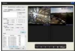
text_image
Screenshot of a video editing software interface showing timeline, preview window, and file properties panel with Chinese text.PICTURE 4-25
At this point, you can either play back or save the files. You can also export and save the files in the .avi format so they can be viewed by conventional video playback software. In addition to the normal playback buttons, the Playback Bar at the bottom of the window lets you view the play list of selected files or open a file saved onto your computer for playback.
E-Map
This brings up a map image - set in the E-Map tab under the Setting Management menu described above.
The map (a.jpg file) can show a building's layout, or in the case of multiple NVRs, a wider region. It is useful for determining where an event is taking place.
Right-clicking in the E-Map window will allow you to open the same configuration window found by using the tab.
Dragging the map in the big window will allow you to move between areas as shown in the larger scale map in the upper left corner.
Within the E-Map window itself, use the directional arrows to navigate around the map.
Double clicking on a camera's icon on the map will open the live video feed in the Real Time Viewer.
Right-clicking on a camera's icon will allow you to view a camera's name and the name of the device it is connected to. You can also open that camera's video food in a separate pop-up window.
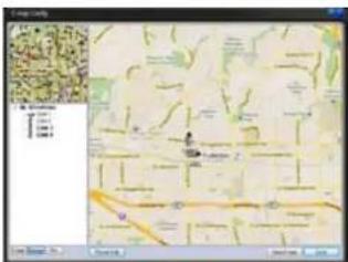
text_image
Screenshot of a mobile app interface displaying a map with location markers and a grid of icons, likely for geographic or data visualization purposes.PICTURE 4-26
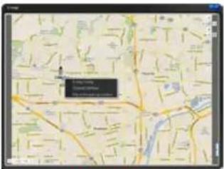
text_image
Map 100 Map 101PICTURE 4-27
Configuration - This last button has two features; Password Change and Options. Password Change allows you to change your user password. Clicking on Options opens a new window.
In this window you can set the save path for locally recorded files and images, rules for how they are named, and attributes for how PSS operates on your computer.
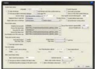
text_image
Scanned document form with multiple columns of text, tables, and checkboxes, likely a form or report.PICTURE 4-28
Device Health Status
This displays the status of connected devices, including NVRs and cameras, but also the NVR's hard drive. Double-clicking on this window will open the Alarm Record.
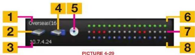
text_image
1 2 3 Overseas(16) 10.7.4.24 4 5 6 7 8 PICTURE 4-29Item Name Description
| 1 Name Shows the device name and number of channels. | |
| 2 Hard Drive Status Shows whether the hard drive is functioning normally, is damaged or missing. | |
| 3 IP NMR's IP address | |
| 4 Hard Drive Capacity Shows how full the hard drive is. | |
| 5 Encoder/Decoder Indicates problems with encoding/decoding of the audio stream (if any) | |
| 6 Camera Status Green Indicates camera is recording | |
| 7 Alarm Status Red indicates an alarm | |
| 8 External Alarm Blue indicates an external alarm | |
MOBILE SURVEILLANCE
CHAPTER 5
In addition to remotely monitoring your phone over the Internet or a local network, you can view live feeds and recorded events on your iPhone, iPad, Android mobile device, Symbian, Windows Mobile or BlackBerry smartphone using free software.
Before you can access your DVR via a smartphone, you must have completed Port Forwarding for ports 80 and 37777 as discussed in Section 2.3.
These mobile applications are designed to work with DVRs and NVRs as well as IP cameras operating in a stand-alone role. Therefore, there will be certain features and functions which are not available for use with your camera, simply because your camera does not have the same features found on a complete system. The primary purpose of accessing your camera using a mobile device is to view the live video. You will not be able to access the camera's internal memory (if available) but some of the programs, including the GC View app, will allow you to record video directly to your mobile device.
5.1 IPHONE AND IPAD
In order to monitor your camera using your iPhone or iPad, you will need to install either the Q-See QC View app for smartphones or Q-See QC View HD app if you're using a tablet. These are available for free through the Apple AppStore by searching for "Q-See." Install either one as you would any other AppStore application.
Both versions have identical functionality. The HD version for the iPad differs in that you can view 16 cameras simultaneously and the viewing resolution is greater to take advantage of the tablet's higher resolution screen.
For smartphones:

Q-See QC View
Utilities
Released Apr 28, 2012
INSTALL
For tablets:

Q-See QC View HD
Utilities
Released May 2, 2012
INSTALL
PICTURE 5-1
STEP 1. To launch QC View, simply tap on its icon in your app menu.
STEP 2. Upon launch, the program will display its main menu. To view your camera, you will need to add it using the Device Manager option.

text_image
Home Real-time Monitor Playback Device Manager Event List Channel Config Push Config Favorites Local Config HelpPICTURE 5-2
STEP 3. A connection to our Demonstration system is already pre-loaded on the application. You can remove this from your list at any time, but it offers an easy option to get the feel of how to use the program.
STEP 4. Click on Add to begin the process of configuring QC View to access your camera.
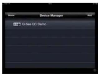
text_image
Device Manager Add Q-See QC DemoPICTURE 5-3
STEP 5. You will need to enter certain details in order to access your camera. You will most likely want to set up two methods to connect to your system - one for when you're on the same network (ie; within the same building as the camera and able to connect wirelessly to your network) as well as one for times when you're away and will be accessing using the Internet IP address.
DVR Title: This should be a descriptive name, such as "Camera Local" or "Camera Internet" to help you utilize the proper connection method.
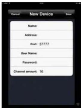
text_image
Cancel New Device Save Name: Address: Port: 37777 User Name: Password: Channel amount: 16PICTURE 5-4
Server: Enter the LAN or Internet IP address as appropriate. If you set up a domain name with MyQ-see.com, then you can enter that name for Internet connections.
Port: 37777.
User Name: admin (by default or use whatever user ID that you set in the camera)
Password: admin (by default or whatever password you set in the camera)
Channel amount: Since your camera offers only a single view, there will only be a single channel available.
OPERATION
Once you have selected the device you wish to monitor, you are able to view the live feed from your camera. You may capture still images from the video by pushing the Snapshot button. These images will be found in your device's Photos menu.
The Main menu gives you access to all of the functions of QC View. Touching the device's Return button - whether on screen, or on a keypad - while in one window will return you back to this menu.
Initially, you will need to turn on your camera's display individually from the Device List. You can bring up the device list by tapping on its icon on the right of the screen, or by double-tapping in an empty video display. Even though the application will show multiple channels available, there is only one channel from the camera. A green surround around your camera's video shows that this is the "active" channel and any actions performed using the buttons on the left of the screen will affect that channel.
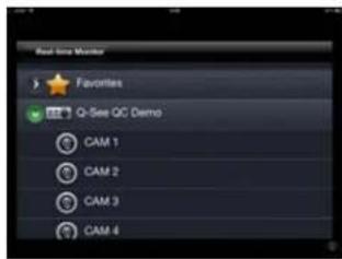
text_image
Real-time Monitor Favorites Q-See QC Demo CAM 1 CAM 2 CAM 3 CAM 4PICTURE 5-5
Real-time Monitor: This window is where you will view the feed from your camera.
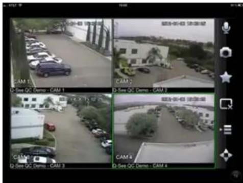
text_image
CAM 1 Q-See QC Demo - CAM 1 CAM 2 Q-See QC Demo - CAM 2 CAM 3 Q-See QC Demo - CAM 3 CAM 4 Q-See QC Demo - CAM 4PICTURE 5-6
Audio (requires audio-enabled camera)
Snapshot (saves to Local Files)
Favorites (groups of channels)
Close Channel
Device list
PTZ Controls
Playback: This is not available when monitoring a camera.
Event List: When you set up Push Config (below) to notify you of events such as motion detection, camera masking (video blind) or a local alarm triggered at the DVR itself, QC View will keep a log of these events which can be reviewed in this list.
Channel Config: You are able to adjust the configuration of each video channel to optimize the performance on your iPad or iPhone. These settings will not change those set on your DVR, but instead allow you to compensate for being in areas where with poor connectivity, for example.
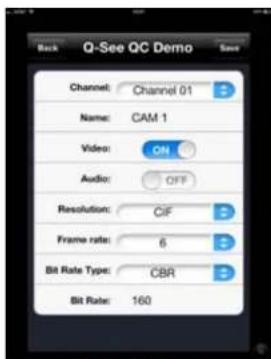
text_image
Back Q-See QC Demo Channel: Channel 01 Name: CAM 1 Video: ON Audio: OFF Resolution: CIF Frame rate: 6 Bit Rate Type: CBR Bit Rate: 160PICTURE 5-7
Push Config: This window provides you a check list allowing you to indicate which cameras will alert you based on motion detection, camera masking, or a local alarm triggered at the DVR itself. When Push is activated, you will receive alerts on your mobile device even when you're not currently in the program. You can click on an alert and it will take you directly to video playback of the incident that triggered the alert.
Favorites: This is not applicable for the camera as it only has a single channel.
Local Config: This is not applicable to your camera.
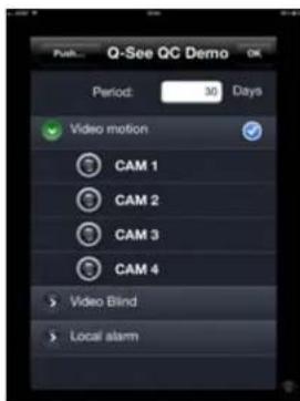
text_image
Q-See QC Demo Period: 30 Days Video motion CAM 1 CAM 2 CAM 3 CAM 4 Video Bind Local alarmPICTURE 5-8
Help: Opens the internal help documentation.

NOTE! If you like this application, please leave positive feedback in the App Store.
5.2 ANDROID
In order to monitor your camera using your Android smartphone or tablet, you will need to install either the Q-See QC View app for smartphones or Q-See QC View HD app if you're using a tablet. These are available for free through the Android market by searching for "Q-See." Install either one as you would any other Android application.
Both versions have identical functionality. The HD version for the Android tablet differs in that you can view 16 cameras simultaneously and the viewing resolution is greater to take advantage of the tablet's higher resolution screen.
For smartphones:

Q-See QC View
DPSI
Free
For tablets:

Q-See QC View HD
DPSI
Free
PICTURE 5-9
STEP 1. To launch QC View, simply tap on its icon in your app menu.
STEP 2. Upon launch, the program will display its main menu. To view your DVR, you will need to add it using the Device Manager option.

text_image
Q-See QC View Real-time Monitor Play Back Device Manager Alarm Push Favorites Local Files Config HelpPICTURE 5-10
STEP 3. A connection to our Demonstration system is already pre-loaded on the application. You can remove this from your list at any time, but it offers an easy option to get the feel of how to use the program.
STEP 4. Click on Add to begin the process of configuring QC View to access your camera.
STEP 5. You will need to enter certain details in order to access your camera. You will most likely want to set up two methods to connect to your system - one for when you're on the same network (ie; within the same building as the camera and able to connect wirelessly to your network) as well as one for times when you're away and will be accessing using the Internet IP address.
DVR Title: This should be a descriptive name, such as "Camera Local" or "Camera Internet" to help you utilize the proper connection method.
Server: Enter the LAN or Internet IP address as appropriate. If you set up a domain name with MyQ-see.com, then you can enter that name for Internet connections.

text_image
7:35 PM Back Device Manager Add Demo SitePICTURE 5-11

text_image
Back 7:35 PM Save DVR Title: Server: Port: 37777 User Name: Password: MaxChannel: 16PICTURE 5-12
Port: 37777.
User ID: admin (by default or use whatever user ID that you set in the camera)
Password: admin (by default or whatever password you set in the camera)
Max Channel: This will be 1.
OPERATION
Once you have selected the device you wish to monitor, you will be able to observe live video from the camera. You may capture still images from the video by pushing the Snapshot button.
The Main menu gives you access to all of the functions of QC View. Touching the device's Return button - whether on screen, or on a keypad - while in one window will return you back to this menu.
Initially, you will need to turn on your camera's display individually from the Device List. You can bring up the device list by tapping on its icon on the right of the screen, or by double-tapping in an empty video display. Even though a multi-channel display will have more than one space for video available, the camera can only provide one video stream.
The green surround around your camera's view indicates that it is the "active" channel and any actions performed using the buttons on the left of the screen will affect that channel.
Real-time Monitor: This window is where you will view the feeds from your cameras.
Play Back: You cannot use this function with a camera.

text_image
10.15.3.81-Camera DW480 10.15.3.81-Camera PW480 10.15.3.81 On S06579 10.15.3.81 Camera PW480PICTURE 5-13
Snapshot (saves to Local Files)
Device list
Favorites (groups of channels)
Close Channel
Audio (requires audio-enabled camera)
PTZ Controls
Alarm Push: This window provides you a check list allowing you to indicate which cameras will alert you based on motion detection, camera masking, or a local alarm triggered at the DVR itself. When Alarm Push is activated, you will receive alerts on your mobile device even when you're not currently in the program. You can click on an alert and it will take you directly to video playback of the incident that triggered the alert.
Favorites: This feature isn't applicable as there is only one possible channel configuration from your camera.
Local Files: Snapshots captured from the Real-time Monitor are stored here.
Config: This operation does not work while monitoring stand-alone cameras.
Help: Opens the internal help documentation.
5.3 BLACKBERRY
The QC-Series IP cameras support phones running Blackberry Version 5.0. You will need to install a program called DMSS in order to monitor your camera using your BlackBerry smartphone. This software is available both on the CD that accompanied your camera as well as via download from www.Q-See.com/Support. If you are downloading the software, begin with Step 1, below. Otherwise, copy the software from the CD to your computer's desktop and begin with Step 3.
STEP 1. Download the phone software from Q-See.com/Support by looking up your camera's model number and then selecting BlackBerry OS Smart Phone Software.
STEP 2. Extract the files from the software download. You will have two files; dmss.alx and dmss.cod. Save these files to your desktop.

text_image
Microsoft Windows 2003 Microsoft Windows 2004 Microsoft Windows 2005 Microsoft Windows 2006 Microsoft Windows 2007 Microsoft Windows 2008 Microsoft Windows 2009 Microsoft Windows 2010 Microsoft Windows 2011 Microsoft Windows 2012 Microsoft Windows 2013 Microsoft Windows 2014 Microsoft Windows 2015 Microsoft Windows 2016 Microsoft Windows 2017 Microsoft Windows 2018 Microsoft Windows 2019 Microsoft Windows 2020 Microsoft Windows 2021 Microsoft Windows 2022 Microsoft Windows 2023 Microsoft Windows 2024 Microsoft Windows 2025 Microsoft Windows 2026 Microsoft Windows 2027 Microsoft Windows 2028 Microsoft Windows 2029 Microsoft Windows 2030 Microsoft Windows 2031 Microsoft Windows 2032 Microsoft Windows 2033 Microsoft Windows 2034 Microsoft Windows 2035 Microsoft Windows 2036 Microsoft Windows 2037 Microsoft Windows 2038 Microsoft Windows 2039 Microsoft Windows 2040 Microsoft Windows 2041 Microsoft Windows 2042 Microsoft Windows 2043 Microsoft Windows 2044 Microsoft Windows 2045 Microsoft Windows 2046 Microsoft Windows 2047 Microsoft Windows 2048 Microsoft Windows 2049 Microsoft Windows 2050 Microsoft Windows 2051 Microsoft Windows 2052 Microsoft Windows 2053 Microsoft Windows 2054 Microsoft Windows 2055 Microsoft Windows 2056 Microsoft Windows 2057 Microsoft Windows 2058 Microsoft Windows 2059 Microsoft Windows 2060 Microsoft Windows 2061 Microsoft Windows 2062 Microsoft Windows 2063 Microsoft Windows 2064 Microsoft Windows 2065 Microsoft Windows 2066 Microsoft Windows 2067 Microsoft Windows 2068 Microsoft Windows 2069 Microsoft Windows 2070 Microsoft Windows 2071 Microsoft Windows 2072 Microsoft Windows 2073 Microsoft Windows 2074 Microsoft Windows 2075 Microsoft Windows 2076 Microsoft Windows 2077 Microsoft Windows 2078 Microsoft Windows 2079 Microsoft Windows 2080 Microsoft Windows 2081 Microsoft Windows 2082 Microsoft Windows 2083 Microsoft Windows 2084 Microsoft Windows 2085 Microsoft Windows 2086 Microsoft Windows 2087 Microsoft Windows 2088 Microsoft Windows 2089 Microsoft Windows 2090 Microsoft Windows 2091 Microsoft Windows 2092 Microsoft Windows 2093 Microsoft Windows 2094 Microsoft Windows 2095 Microsoft Windows 2096 Microsoft Windows 2097 Microsoft Windows 2098 Microsoft Windows 2099 Microsoft Windows 2100PICTURE 5-14

NOTE! The file you download will be a.rar formatted archive. We use this format to compress the file to the smallest possible size to speed up your downloading. If you need an extraction utility to open it, you can find free software at http://rarlabs.com/download.htm (PC) or http://www.unrarx.com (Mac)
STEP 3. Connect your Phone to the PC using a USB cable.
STEP 4. Run BlackBerry Desktop Manager and make sure it detects the application.
STEP 5. Click on Application Loader.
STEP 6. On Add/Remove Application, click on Start. Then click on Browse and Go to the Location where you have the dmss.alx file.
STEP 7. Once you finish uploading, you will see DMSS application in your blackberry (in the Download folder).
STEP 8. Click on the DMSS icon to launch the program. If this is your first time using this application on your phone, you will be presented with the login screen shown in Picture 5-16.
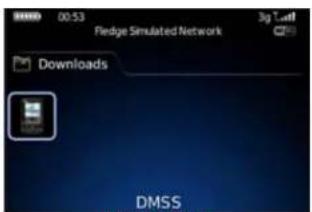
text_image
00:53 Fledge Simulated Network 3g Train Downloads DMSSPICTURE 5-15
STEP 9. Enter the following details:
Address: Enter the Server IP (your public IP)
Port: 37777.
User ID: admin (by default or use whatever user ID that you set in the camera)
Password: admin (by default or whatever password you set in the camera)
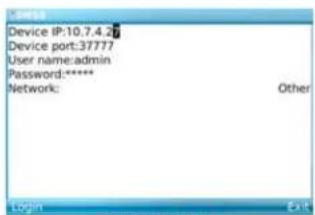
text_image
Device IP:10.7.4.2 Device port:37777 User name:admin Password:**** Network: Other Login ExitPICTURE 5-16
After you log in, you will be able to see your camera listed as a channel available to monitor.
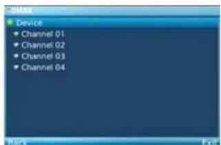
text_image
Device Channel 01 Channel 02 Channel 03 Channel 04 Back ExitPICTURE 5-17
Once you've selected your camera, it will display along with a list of selections.
Camera - Go back to the camera selection window. You only have one camera to choose from.
PTZ - Display/Hide PTZ controls. This is not functional with your camera.
Full - Switch to full-screen display (no controls). Clicking on the phone's scroll ball will return the display to normal.
Set - Go to Video Monitor Interface
Exit - Exit the software.

natural_image
Interior view of an office or service center with glass partitions and a desk (no visible text or symbols)PICTURE 5-18
Set
This returns you to the Login window where you can enter the information to connect to another DVR, NVR or camera or exit DMSS. You can also use the Exit button at the bottom of the screen.

text_image
Device IP:10.7.4.2# Device port:37777 User name:admin Password:**** Network: Other Login ExtPICTURE 5-19
5.4 SYMBIAN
QC-Series IP cameras can be configured to be remotely monitored by a phone running the 3rd and 5th editions of the Symbian OS through the use of the DMSS software included on the disk that came with your camera or available via download from www.Q-See.com/Support. If you are downloading the software, begin with Step 1, below. Otherwise, copy the software from the CD to your computer's desktop and begin with Step 3.
STEP 1. Download the phone software from Q-See.com/Support by looking up your camera's model number and then selecting Symbian OS Smart Phone Software.
STEP 2. Extract the DMSS.sis application from the archive and save it to your desktop.
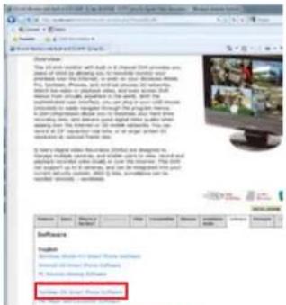
text_image
The Amazon Prime Video will be built in a digital CNT provides an app to create a new version of the Amazon Prime Video. It is also created by the Amazon Prime Video and then created by the Amazon Prime Video. The Amazon Prime Video will have been created by the Amazon Prime Video. The Amazon Prime Video will have been created by the Amazon Prime Video. The Amazon Prime Video will have been created by the Amazon Prime Video. The Amazon Prime Video will have been created by the Amazon Prime Video. The Amazon Prime Video will have been created by the Amazon Prime Video. The Amazon Prime Video will have been created by the Amazon Prime Video. The Amazon Prime Video will have been created by the Amazon Prime Video. The Amazon Prime Video will have been createdby the Amazon Prime Video. The Amazon Prime Video will have been created by the Amazon Prime Video. The Amazon Prime Video will have been created by the Amazon Prime Video. The Amazon Prime Video will have been created by the Amazon Prime Video. The Amazon Prime Video will have been created by the Amazon Prime Video. The Amazon Prime Video will have been created by the Amazon Prime Video. The Amazon Prime Video will have been created by the Amazon Prime Video. The Amazon Prime Video will have been created by the AMOS software. The Amazon Prime Video will have been created by the Amazon Prime Video. The Amazon Prime Video will have been created by the Amazon Prime Video. The Amazon Prime Video will have been created by the Amazon Prime Video. The Amazon Prime Video will have been created by the AMOS software. The Amazon Prime Video will have been created by the AMOS software.PICTURE 5-20

NOTE! The file you download will be a .rar formatted archive. We use this format to compress the file to the smallest possible size to speed up your downloading. If you need an extraction utility to open it, you can find free software at http://rarlabs.com/download.htm (PC) or http://www.unrarx.com (Mac)
STEP 3. Connect your phone to the computer using a wireless or infrared connection to send the software to your phone as a message. Or, you can use the Nokia PCSuite software with a local connection to transfer DMSS to your phone.
STEP 4. Double-click on the DMSS icon to launch it.

text_image
Installations 4:55 am App. mgr. AudioStream Debug Agent Bilingual Di... DMSS eshell MSS netsdktest nodilSocket testsocket testsocket WebClient Options Open BackPICTURE 5-21
STEP 5. Enter the following details:
Address: Enter the Server IP (your public IP)
Port: 37777.
User ID: admin (by default or use whatever user ID that you set in the camera)
Password: admin (by default or whatever password you set in the camera)
STEP 6. Once you've entered the information and then the Login button, you'll be connected to your camera and can chose which channel to view. Your camera will only display one channel as available.
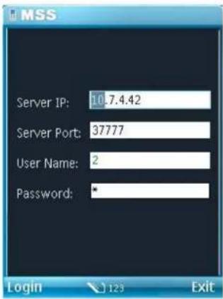
text_image
MSS Server IP: 10.7.4.42 Server Port: 37777 User Name: 2 Password: * Login 123 ExitPICTURE 5-22
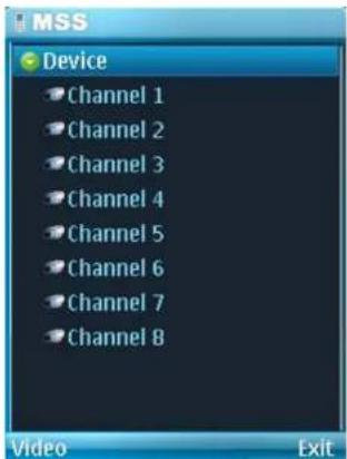
text_image
MSS Device Channel 1 Channel 2 Channel 3 Channel 4 Channel 5 Channel 6 Channel 7 Channel 8 Video ExitPICTURE 5-23
STEP 7. Once you've selected your camera, it will display along with a list of selections.
Camera - Go back to the camera selection window.
PTZ - Display/Hide PTZ controls. This is not functional with your camera.
Full - Switch to full-screen display (no controls). Clicking on the phone's scroll ball will return the display to normal.
Video - Go to Video Monitor Interface
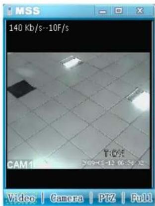
text_image
MSS 140 Kb/s--10F/s CAM1 T:64 2009-05-12 06:54:12 Video | Camera | PTZ | FullPICTURE 5-24
5.5 WINDOWS MOBILE
Your QC-Series IP camera can be configured to be remotely monitored by a phone running the Windows Mobile operating system through the use of the DMSS software included on the disk that came with your camera or available via download from www.Q-See.com/Support If you are downloading the software, begin with Step 1, below. Otherwise, copy the software from the CD to your computer's desktop and begin with Step 3.
STEP 1. Download the phone software from Q-See.com/Support by looking up your DVR's model number and then selecting Windows Mobile Pro Smart Phone Software.
STEP 2. Extract the DMSS.cab file from the archive and save it to your desktop.
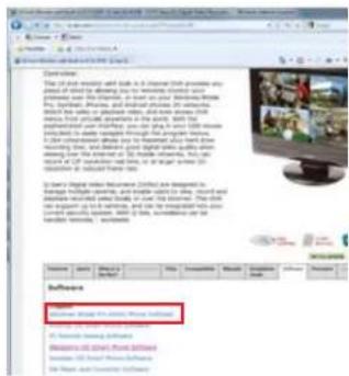
text_image
Software New York Times Software Software: New York Times Software Software: New York Times Software Software: New York Times SoftwarePICTURE 5-25

NOTE! The file you download will be a.rar formatted archive. We use this format to compress the file to the smallest possible size to speed up your downloading. If you need an extraction utility to open it, you can find free software at http://rarlabs.com/download.htm (PC) or http://www.unrarx.com (Mac)
STEP 3. Connect your phone to the computer and transfer the software to your phone in the usual manner. You will be asked whether you wish to install the software to your device or storage card.
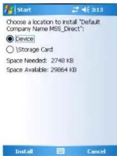
text_image
Choose a location to install "Default Company Name MSS_Direct": ● Device ○ \Storage Card Space Needed: 2748 KB Space Available: 29864 KBPICTURE 5-26
STEP 4. After the program is installed, you can launch it from the Programs menu.
text_image
Programs Games ActiveSync Calculator DMSS Download Agent Excel Mobile File Explorer Notes Pictures & Videos Pocket MSN PowerPoint Mobile SearchPICTURE 5-27
STEP 5. Upon launch, you will be presented with a login window. Enter the following details:
Address: Enter the Server IP (your public IP)
Port: 37777.
User ID: admin (by default or use whatever user ID that you set in the camera)
Password: admin (by default or whatever password you set in the camera)
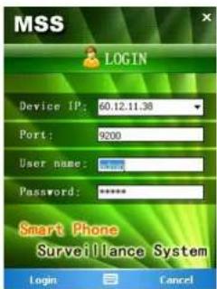
text_image
MSS LOGIN Device IP: 60.12.11.38 Port: 9200 User name: Password: ***** Smart Phone Surveillance System Login CancelPICTURE 5-28
STEP 7. Once you've logged in, select your camera by double-clicking on its name or by clicking on it once and then selecting the Video button. You will now be in the Video Monitor interface.
Camera - Go back to the camera selection window.
PTZ - Not functional with this camera.
Full - Switch to full-screen display (no controls). You can also click on the video itself, or use the maximize icon in the upper right of the screen.
Video - Go to Video Monitor Interface.
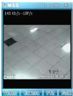
text_image
140 Kb/s--10F/s CAM: 1 Video | Camera | PIZ | FullPICTURE 5-29
To exit DMSS, click the X at the top right corner of the screen.
Q-SEE PRODUCT WARRANTY
Q-See is proud to back all of our products with a conditional service warranty covering all hardware for 12 months from the date of purchase. Additionally, our products also come with a free exchange policy that covers all manufacturing defects for one month from the date of purchase. Permanent upgrading service is provided for the software.
Liability Exclusions:
Any product malfunction or abnormalities in operation or damage caused by the following reasons are not within the free service scope of our company:
- Equipment damage caused by improper operation.
- Improper equipment operation environment and conditions (e.g., improper power, extreme environmental temperatures, humidity, lightning and sudden surges of electricity).
- Damage caused by acts of nature (e.g., earthquake, fire, etc).
- Equipment damage caused by the maintenance of personnel not authorized by Q-See.
- Product sold over 12 months ago.
In order to fulfill the terms of your warranty, you must complete the registration process after purchasing our product. To do this, simply fill out the User's Information Card on our website at www.Q-See.com

QUESTIONS OR COMMENTS? CONTACT US
PRODUCT SUPPORT, DOWNLOADS, FIRMWARE UPDATES & MANUALS
24/7 Technical Resources
Live Chat (M-F, 9-5 PST)
www.Q-See.com/Support
simplicity - quality - technology