
Enterprise HERC96T24S - Security Camera HONEYWELL - Free user manual and instructions
Find the device manual for free Enterprise HERC96T24S HONEYWELL in PDF.

| Product Type | RAID and JBOD Storage System |
| Model Number | Enterprise HERC96T24S |
| Available Configurations | 2U, 3U, 4U; RAID or JBOD |
| Voltage | 100-240 VAC auto-ranging |
| Power Consumption (12-bay) | Idle: 230 W, Busy: 245 W |
| Power Supply | Dual or triple hot-swap redundant with PFC, N+1 design |
| Operating Temperature | 32° to 104°F (0° to 40°C) |
| Relative Humidity | 5 to 95% non-condensing |
| Dimensions (2U model) | 3.5 x 17.5 x 20.2 in (8.8 x 44.6 x 51.4 cm) |
| Weight (2U without drives) | 39.9 lb (18.1 kg) |
| Drive Interface | SAS 3/6 Gbps |
| Number of Drive Bays | 12, 16, or 24 (depending on chassis) |
| Hot-Swappable Components | PSU, cooling modules, hard drives |
| RAID Controller | Embedded firmware, supports RAID levels via LCD or serial |
| Cache Backup Module | Optional BBU + flash module for data protection |
| Management | LCD keypad, serial port, Ethernet, firmware utility |
| Safety Compliance | UL/CSA 60950-1 |
| Emissions | FCC Class A |
Frequently Asked Questions - Enterprise HERC96T24S HONEYWELL
User questions about Enterprise HERC96T24S HONEYWELL
0 question about this device. Answer the ones you know or ask your own.
Ask a new question about this device
Download the instructions for your Security Camera in PDF format for free! Find your manual Enterprise HERC96T24S - HONEYWELL and take your electronic device back in hand. On this page are published all the documents necessary for the use of your device. Enterprise HERC96T24S by HONEYWELL.
USER MANUAL Enterprise HERC96T24S HONEYWELL
Enterprise NVR Series
RAID and JBOD Systems
User Guide
User Guide
Revisions
Issue Date Revisions
A 03/2014 New document.
Contents
Cautions and Warnings 7
Regulatory Statements 8
Safety Instructions 9
Warranty and Service. 11
About This Manual 13
Overview of Contents. 13
Related Documents 14
1 Introduction.... 15
Product Overview. 15
Main System Components 16
Rear Panel 17
Chassis 17
Front Panel Components. 20
Rear Panel Components 22
System Monitoring Features 26
Hot-swapping....27
2 Hardware Installation 29
Installation Procedures Overview 29
Installing Cache Backup Modules 30
Rack Mounting the Enclosure 31
Installing Hard Drives. 33
3 System Connection 37
System Connection Overview 37
SAS-Host RAID Connections. 41
JBOD Connections 43
Management Console Connections 46
Power Connections. 47
4 System Monitoring 51
System Monitoring Overview.... 51
Monitoring Front Panel Components 52
Monitoring Rear Panel Components 55
Alarms and I2C Bus 61
Restoring Default System Settings....62
5 System Maintenance 65
Replacing Controller Modules 65
Replacing Memory Modules 67
Replacing Cache Backup Modules 68
Replacing Power Supply Units 70
Replacing Cooling Modules 72
Replacing Hard Drives 74
Appendix A Technical Specifications. 77
Cautions and Warnings
 |  |  |  | THIS SYMBOL INDICATES THAT DANGEROUS VOLTAGE CONSTITUTING A RISK OF ELECTRIC SHOCK IS PRESENT WITHIN THE UNIT. |
| CAUTION: TO REDUCE THE RISK OF ELECTRIC SHOCK,DO NOT REMOVE COVER (OR BACK).NO USER SERVICEABLE PARTS INSIDE.REFER SERVICING TO QUALIFIED SERVICE PERSONNEL. |  | THIS SYMBOL INDICATES THAT IMPORTANT OPERATING AND MAINTENANCE INSTRUCTIONSACCOMPANY THIS UNIT. | ||
WARNING Install the enclosure in a restricted access location where access is only given to service persons and users who have been instructed about the reasons for the restrictions and any precautions that must be taken. The location should only be accessible by an authorized person through the use of a tool, a lock and key, or other secure means of entry. Access is controlled by the authority responsible for the location.
WARNING Risk of electric shock. Access to this equipment should only be granted to trained operators and service personnel who understand the possible hazardous consequences of accessing non-field-serviceable components, such as the system backplane or power supplies. Unplug the system before moving it or whenever it becomes damaged.
WARNING Risk of explosion if battery is replaced by an incorrect type. Dispose of used batteries according to local laws.
WARNING Check proper grounding before powering on the enclosure. The AC power cords provide the main earth connection. Ensure reliable earthing with power supply connections other than direct connections to the branch circuit (for example, when using power strips).
WARNING Install the enclosure according to the specifications on the enclosure label. Provide a suitable power source with electrical overload protection. Do not overload the AC supply branch circuit that provides power to the rack. The total rack load should not exceed 80 percent of the branch circuit rating.
Regulatory Statements
FCC Compliance Statement
Information to the User: This equipment has been tested and found to comply with the limits for a Class A digital device, pursuant to part 15 of the FCC Rules. These limits are designed to provide reasonable protection against harmful interference when the equipment is operated in a commercial environment. This equipment generates, uses, and can radiate radio frequency energy and, if not installed and used in accordance with the instruction manual, may cause harmful interference to radio communications. Operation of this equipment in a residential area is likely to cause harmful interference in which case the user will be required to correct the interference at his own expense.
Note Changes or modifications not expressly approved by the party responsible for compliance could void the user's authority to operate the equipment.
Canadian Compliance Statement
Manufacturer's Declaration of Conformance
North America The equipment supplied with this guide conforms to UL 60950-1 and CSA C22.2 No. 60950-1.
Europe The manufacturer declares that the equipment supplied is compliant with the essential protection requirements of the EMC directive 2004/108/EC and the Low Voltage Directive (LVD) 2006/95/EC, conforming to the requirements of standards EN 55022 for emissions, EN 50130-4 for immunity, and EN 60950 for electrical equipment safety.
Waste Electrical and Electronic Equipment (WEEE)
Correct Disposal of this Product (applicable in the European Union and other European countries with separate collection systems).
This product should be disposed of, at the end of its useful life, as per applicable local laws, regulations, and procedures.
Safety Instructions
Read these instructions carefully before you install, operate, or transport Honeywell Enterprise NVR RAID and JBOD hardware.
Installation and Operation
- Install the rack cabinet and the associated equipment at a site where the ambient temperature (special room cooling equipment may be required) stays lower than:
- 95^ F (35° C) if your system has a battery backup unit.
- 104^ F ( 40^ C) if your system does not have a battery backup unit.
• Install the power source socket outlet near the enclosure where it is easily accessible and ground the rack cabinet.
- Secure airflow clearance inside and around the rack cabinet. For proper ventilation, a minimum clearance of 1 inch (2.5 cm) is required between the front of the enclosure and the rack cover and a minimum of 7–8 inches (18–20 cm) is required on the rear side.
- The hard drives and drive trays should only be installed into the system after rack-mount installation is completed.
- All drive trays (even if they do not contain a hard drive) must be installed into the enclosure. Leaving a drive bay or module slot open will severely affect the airflow efficiency within the enclosure, and will consequently lead to system overheating.
- Do not cover the enclosure openings.
- Route the cables inside the rack cabinet.
- Do not leave drive bays empty as it will affect airflow efficiency.
- Secure each enclosure module using its retaining screws.
- Place power cords and other cables away from foot traffic. Do not place items on top of power cords and make sure they do not rest against data cables.
• Install all modules to the enclosure before powering on the system.
- Ensure that the correct power range is being used before powering on.
- Do not remove covers or replaceable modules if they are not faulty.
- If the system is not going to be used for a long period of time, disconnect it from the power mains to avoid transient over-voltage.
- For power source redundancy, please make sure that the two PSUs are plugged into two different power sources (with different circuit breakers).
Service and Maintenance
- Keep the faulty module in place until you have a replacement unit. An empty module greatly affects the airflow efficiency within the enclosure.
- During service operation, place the enclosure on a soft and clean surface to prevent exterior damage. Do not place tools or other items on top of the enclosure.
- When transporting the enclosure, repackage all disk drives separately in the original package foam blocks. Replaceable modules can stay in the enclosure if you are using the original package; if not, repackage them separately as well.
- Disconnect the power cords before servicing or cleaning the enclosure.
- Use a slightly moistened paper sheet or cloth for cleaning. Avoid using liquid or sprayed detergent.
- When replacing components, insert them as gently as possible while ensuring full engagement. Vibration and shock can easily damage hard drives.
- Only qualified service personnel should open the enclosure.
- Contact service personnel if any of the following situations occurs:
- The power cord or plug is damaged.
- The enclosure has been exposed to moisture.
- The system has not been working properly.
- The enclosure was dropped against a hard surface.
- The enclosure shows obvious signs of breakage.
- To move the enclosure, more than one person might be necessary due to its weight. Drives should be removed from the enclosure beforehand.
- The enclosure ears cannot support the weight of the system. Do not use these finger grips when relocating the system.
ESD Precautions
- Handle the modules by their retention screws, ejector levers, or the module's metal frame/faceplate only. Avoid touching the PCB boards or connector pins.
- Use a grounded wrist strap and an anti-static work pad to discharge static electricity when installing or operating the enclosure.
- Avoid dust, debris, carpets, plastic, vinyl, and styrofoam in your work area.
- Do not remove any module or component from its anti-static bag before installation takes place.
- Drives must not be stacked on top of each other without their protective drive trays. Even when drives are fixed in the drive trays, contacting the exposed PCB or rear-side interface may damage the drives.
Warranty and Service
Subject to the terms and conditions listed on the Product warranty, during the warranty period Honeywell will repair or replace, at its sole option, free of charge, any defective products returned prepaid.
In the event you have a problem with any Honeywell product, please call Customer Service at 1.800.323.4576 for assistance or to request a Return Merchandise Authorization (RMA) number.
Be sure to have the model number, serial number, and the nature of the problem available for the technical service representative.
Prior authorization must be obtained for all returns, exchanges, or credits. Items shipped to Honeywell without a clearly identified Return Merchandise Authorization (RMA) number may be refused.
About This Manual
This manual introduces hardware components of the Honeywell Enterprise NVR Series 2U, 3U, and 4U RAID and 2U and 3U JBOD systems and describes how to install, monitor, and maintain them. This manual is intended for system integrators, installers, and end-user operators.
Overview of Contents
This manual contains the following chapters and appendixes:
- Chapter 1, Introduction, briefly describes RAID and JBOD systems, and provides descriptions of the front and rear panels, main system components, and system monitoring features.
• Chapter 2, Hardware Installation, describes procedures for installing cache backup modules, rack mounting RAID and JBOD enclosures, and installing hard drives. - Chapter 3, System Connection, describes typical connection configurations for RAID and JBOD systems.
- Chapter 4, System Monitoring, provides information about monitoring the status of RAID and JBOD systems through the built-in firmware, the front and rear panel LED indicators, and audible alarms.
- Chapter 5, System Maintenance, describes procedures for replacing controller modules, memory modules, cache backup modules, power supply units, cooling modules, and hard drives.
- Appendix A, Technical Specifications, lists the physical, electrical, operational, and regulatory specifications of the Honeywell Enterprise NVR Series 2U, 3U, and 4U RAID and 2U and 3U JBOD systems.
Related Documents
For additional installation information, refer to the following documents:
• Enterprise JBOD Quick Installation Guide (800-16576)
• Enterprise RAID Quick Installation Guide (800-16577)
Visit http://www.honeywellvideo.com/products/video-systems/accessories/ip/324870.html to find the most up-to-date Enterprise NVR Series RAID and JBOD documentation
1
Introduction
This chapter contains the following sections:
• Product Overview, page 15
• Main System Components, page 16
- Rear Panel, page 17
- Chassis, page 17
• Front Panel Components, page 20
• Rear Panel Components, page 22
• System Monitoring Features, page 26
• Hot-swapping, page 27
Product Overview
Comprised of RAID and JBOD units, RAID systems store hard drives and control the entire storage system. JBOD systems connect to a master RAID system and can expand storage capacities by adding more hard drives.
The RAID and JBOD systems support 3/6 Gbps SAS drive interfaces. The 2U/3U/4U enclosures are designed to accommodate 3.5-inch hard drives. Drive capacity can be expanded by attaching expansion hard drive enclosures (JBODs).
Main System Components
RAID Controller and Interface
Each RAID controller contains a main circuit board and a pre-installed DIMM module.
A cache backup module is available as an optional accessory. It consists of a battery backup unit and flash backup module. Cached data is quickly distributed to a flash backup module with the support of a battery backup unit in the event of a power outage. Because of the shorter discharge time, battery backup unit life expectancy is extended, and data is safely kept in flash regardless of the traditional 72 hours limitation.
The controller's embedded firmware features power-saving modes, variable fan speeds, and exiled drive handling for reducing energy consumption.
JBOD Controller and Interface
The JBOD enclosure is managed by expander controllers that distribute data flow to individual disk drives and report operating status through a proprietary enclosure service via in-band protocols. The enclosure, together with other JBODs, connects to a RAID system and serves as a building block of a scalable configuration.
The firmware supports communications with enclosure devices, SAS disk drives, and a RAID system featuring 6 Gbps SAS expansion ports.
The SAS interface provides ease of cabling through Mini-SAS connectors. With a backplane supporting enterprise-class SAS hard drives, the system is ideal for adding large capacity to a storage pool.
Power Supply Unit and Cooling Modules
2U and 3U Systems
In 2U and 3U systems, two cooling modules are built into the power supply unit (PSU) to protect the system from overheating, while two hot-swappable PSUs provide constant power to the system. The modular nature of the system and the accessibility of all major components also makes the system easy to maintain.
4U Systems
In 4U systems, the cooling modules are located on both sides of the controller at the rear. The controller PSUs have built-in cooling modules that assist the main cooling modules in keeping the system ventilated.
Rear Panel
The secondary controller slot is filled with a dummy cage (D). Some models include an additional cooling module in the center-bottom position.
Chassis
The chassis (or simply "enclosure") is the rugged enclosure that protects the internal hard drives in a RAID or JBOD system. It is designed for installation in a rack or cabinet.
RAID Front Panel
The following illustration shows the front panel configuration of RAID models:
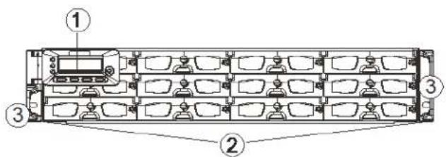
1 LCD Keypad Panel The LCD panel (16 characters × 2 rows) and function keys are used to display system events and configure the firmware.
2 Drive Trays The drive trays are hot-swappable and hold a 3.5-inch hard drive.
3 Handles The handles on either side of the enclosure are used to move the enclosure in and out of the cabinet.
JBOD Front Panel
The following illustration shows the front panel configuration of JBOD models:
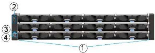
1 Drive Trays Each drive tray is hot-swappable and holds a 3.5-inch hard drive.
2 LED Panel The LED panel indicates the operating status through 5 LEDs.
3 Mute/Service Button The mute button can be used to silence an alarm or indicate to the administrator that the system requires service.
4 Rotary ID Switch The rotary ID switch is used to set a unique ID for each JBOD when connected in a multi-array environment.
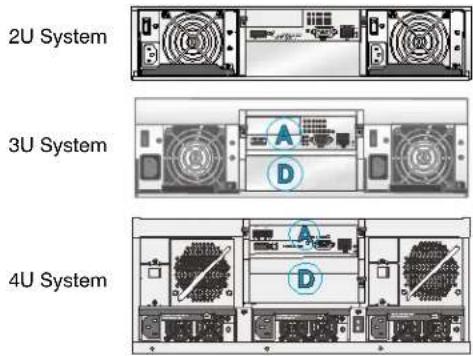
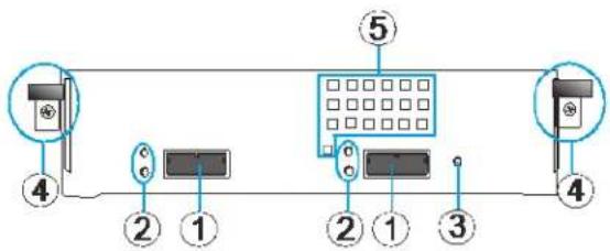
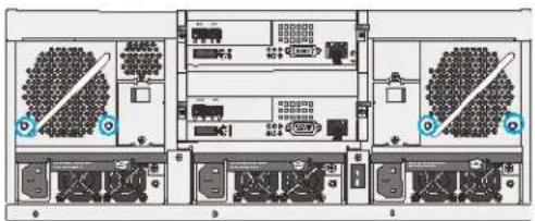
RAID Rear Panel
The following illustration shows the rear panel configurations of 2U, 3U, and 4U RAID models.
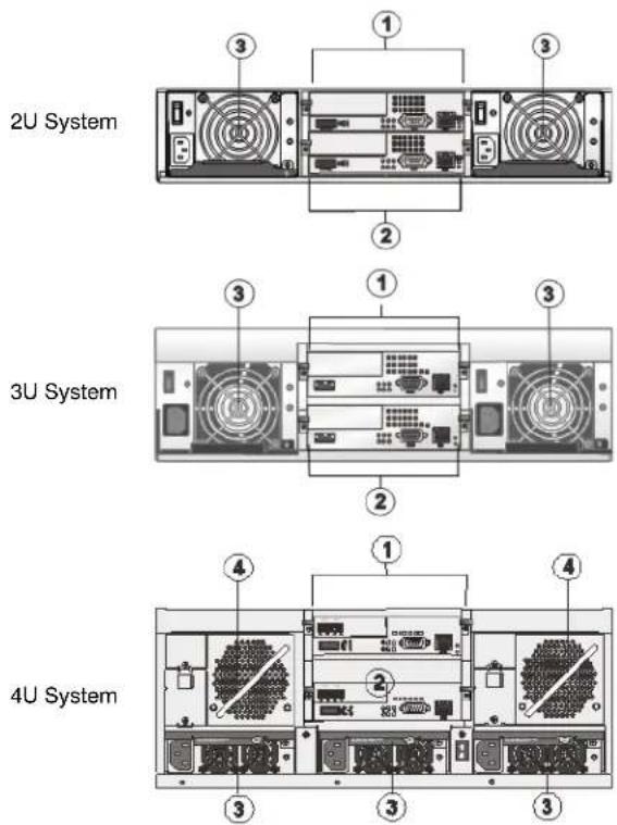
1 Controller A
2 Controller B
3 Power Supply Units and Cooling Modules
4 Cooling Module
CAUTION For single controllers, a dummy cage is placed in the second controller position. Do not remove the dummy cage as this will disrupt the internal airflow.
Hot-swappable power supply units (PSUs) provide power to the RAID system. In 2U and 3U systems, redundant cooling modules ventilate the system (some models have the cooling modules embedded in the PSUs). In 4U systems, the cooling modules are user-serviceable standalone units located on both sides of the controller.
JBOD Rear Panel
The following illustration shows the rear panel configuration of JBOD models.
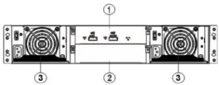
1 Controller A
2 Dummy Cage
3 Power Supply Unit and Cooling Module
CAUTION A dummy cage is placed in the bottom controller position. Do not remove the dummy cage as this will disrupt internal system airflow.
The controller module contains a SAS expander board, which distributes I/Os from and to the managing RAID system. The controller also reports component status through the SAS links to the RAID system.
Hot-swappable PSUs provide power to the JBOD system. A power switch is located on each PSU. Redundant cooling modules ventilate the system.
WARNING An integrated backplane separates the front and rear sections of the enclosure. This circuit board provides logic level signals and low voltage power paths. Thermal sensors and I2C devices are embedded to detect system temperatures and PSU/cooling module operating status. This board contains no user-serviceable components. Accessing the backplane board may cause fatal damage to the system. Also, physical contact with the backplane board may result in electric shock.
Front Panel Components
LCD/LED Panels
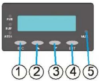
LCD Keypad Panel (RAID Models)
The LCD keypad panel provides full access to RAID configuration settings and system information. Initially, the LCD screen shows the system's model name and the name can be manually assigned for identification in a multi-array configuration.
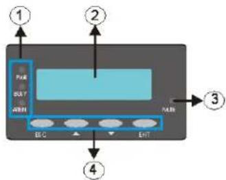
1 Status LEDs From top to bottom, the status LEDs are power (PWR), busy (BUSY), and attention (ATTN).
2 LCD Screen The 16×2-character LCD screen provides access to configuration settings and system information via the firmware-embedded utility.
3 Mute Button Press MUTE to silence an alarm.
4 Function Buttons Press the ENT button for two (2) seconds on the initial screen to enter the main menu. Press the ESC button to clear the current event. Press the UP and DOWN arrow keys to select viewing items.
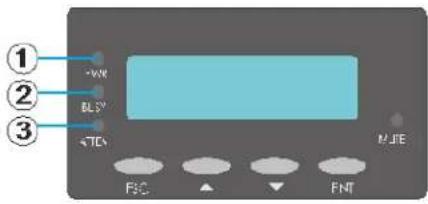
LED Panel (JBOD Models)
The LED panel on a JBOD is located on the chassis ear.
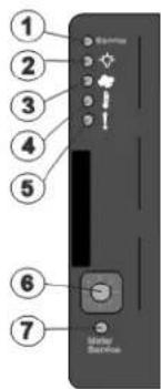
1 Service Status
2 Power Supply Status LED
3 Cooling Module Status LED
4 Temperature Sensor Status LED
5 System Fault Status LED
CAUTION If critical faults are indicated on the LED panel, verify the cause of the problem as soon as possible and contact your system vendor to arrange for a replacement module.
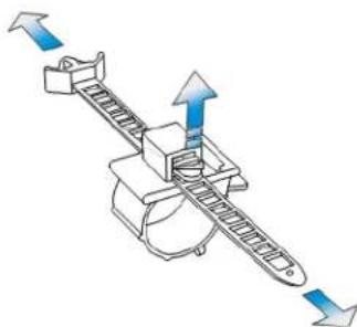
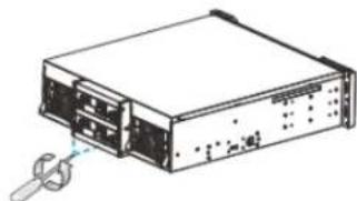
Chassis Ear
Each chassis ear features a finger grip and two holes for securing the enclosure to the front rack posts. In JBOD models, an LED panel is mounted on the left chassis ear. A plastic housing conceals the chassis ear.
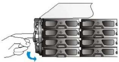
natural_image
Illustration of a hand inserting a device into a multi-chamber rack (no text or symbols visible)To access the finger grips, flip open the panel. You may then grasp the finger grip for retrieving the enclosure out of a rack.
CAUTION The chassis ears cannot support the weight of the system. Do not use these finger grips when re-locating the system.
Drive Tray
The drive tray is designed to accommodate separately purchased 3.5-inch SAS interface hard disk drives.
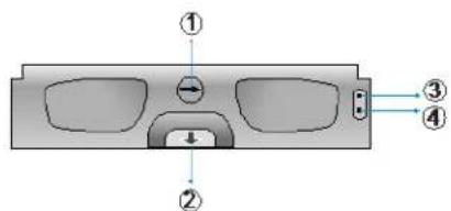
1 Rotary Bezel Lock
2 Release Button
3 Drive Busy LED
4 Power Status LED
CAUTION Be careful not to warp, twist, or contort the drive tray in any way (for example, by dropping it or resting heavy objects on it). If the drive bay superstructure is deformed or altered, the drive trays may not fit into the drive bay.
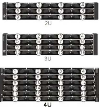
Drive bays are arranged as four bays wide by three, four, or six bays high. The drive bays are numbered from left to right and from top to bottom.
Rear Panel Components
RAID Controller Modules
The following illustration shows the rear panel components of RAID controller modules.
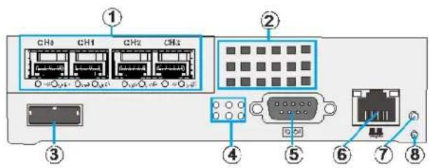
1 H o s t P o r 5 S e r i a l P o r t 2 C o n v e c t i6 Ethernet PortH o l e s
3 SAS Expansion Port
The following illustration shows the rear panel components of JBOD controller modules.
flowchart
graph LR
    A["Device 4"] --> B["Switch"]
    C["Device 2"] --> D["Switch"]
    E["Device 1"] --> F["Switch"]
    G["Device 2"] --> H["Switch"]
    I["Device 1"] --> J["Switch"]
    K["Device 3"] --> L["Switch"]
    M["Device 5"] --> N["Switch"]
    style A fill:#f9f,stroke:#333
    style C fill:#f9f,stroke:#333
    style E fill:#f9f,stroke:#333
    style G fill:#f9f,stroke:#333
    style M fill:#f9f,stroke:#333
    style N fill:#f9f,stroke:#333
1 SAS Expansion Ports
2 SAS Expansion Port LED
3 Controller Status LED
4 Extraction Levers and Retention Screws
5 Convection Holes
The JBOD storage expansion controller contains a circuit board within a metal canister, interfaced through hot-swap docking connectors at the back-end. Two SAS wide ports on the interface faceplate connect to a managing RAID system or to other JBODs.
CAUTION To avoid damaging sensitive components, only remove the JBOD controller module to replace a failed controller.
Cache Backup Module for RAID Models
The cache backup module is available as an optional accessory. The cache backup module consists of a battery backup unit and flash backup module. The cache backup module can sustain cache memory after a power failure. The use of a CBM is highly recommended in order to safeguard data integrity. If you are using a single controller model and would like to install a cache backup module, see Installing Cache Backup Modules, page 30.
1 Battery Backup Unit
2 Flash Backup Module
Note The battery backup unit can be serviced by the user but the flash backup module is not serviceable by the user.
Note
The battery backup unit is only partially charged when shipped. After powering on the system, the battery backup unit will start charging to its full capacity. It normally requires about twelve hours for the battery to be fully charged. If the battery will not fully charge, report the problem to your system vendor. You can also check the status of the battery module using the firmware.
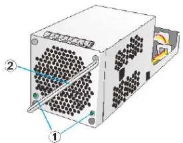
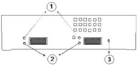
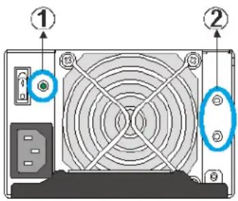
2U and 3U RAID Power Supply Unit and Cooling Module
The 2U and 3U RAID systems come with two redundant, hot-swappable power supply units. Each PSU has a power socket, power switch, PSU status LED, cooling module, cooling module status LEDs, retention screw, and an extraction handle.
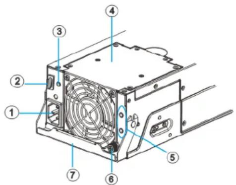
1 Power Socket
2 Power Switch
3 PSU Status LED
4 Cooling Module
5 Cooling Module Status LED
6 Retention Screw
7 Extraction Handle
The cooling modules can operate at three rotation speed settings. Under normal operating conditions, the cooling fans run at the low speed. Under the following conditions, cooling fans raise their rotation speed to increase the airflow:
- Component failure: if a cooling module, PSU, or a temperature sensor fails.
- Elevated temperature: if the temperature breaches the upper threshold set for any of the interior temperature sensors.
- During the system initialization stage, the cooling fans operate at high speed and return to low speed once the initialization process has completed and no erroneous condition detected.
Note
There are two upper temperature thresholds: one for event notification and the other for triggering higher fan rotation speed. The preset value for event notification can be changed using the firmware-embedded configuration utility, while the fan speed trigger cannot be changed.
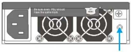
4U RAID Power Supply Unit
The 4U RAID systems are equipped with three redundant, hot-swappable, load-sharing power supply units at the rear of the enclosure. The PSU is housed in a 1U canister containing both the power supply and dedicated cooling modules.
Each PSU has an extraction handle, retention screw, PSU status LED, and a power socket.
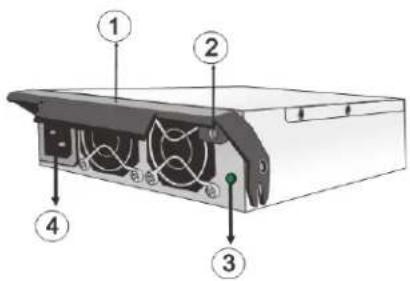
1 Extraction Handle
2 Retention Screw
3 PSU Status LED
4 Power Socket
4U RAID Cooling Module
4U RAID systems have two cooling modules at the rear of the enclosure that provide ventilation. The cooling fans operate at two fan speeds. When the system is operating normally, the cooling fans operate at the lower speed. If a system module fails, or when one of the temperature thresholds has been exceeded, the cooling fans automatically raise their rotation speeds to draw more airflow.
The cooling module has two cooling module fan status LEDs and an extraction handle.
natural_image
3D diagram of a computer power supply unit with labeled components (no text or symbols present)1 Fan Status LED
2 Extraction Handle
System Monitoring Features
RAID and JBOD systems are equipped with a wide range of monitoring functions. These are briefly described below.
Expansion Enclosure Support
Monitoring
A managing RAID system monitors the status of JBOD components:
- Expander controller (presence, voltage, and thermal readings)
- Power supply unit
- Cooling module
• Enclosure thermal sensor
• Service (the service signal to specify a specific enclosure) - Disk drives
JBOD Identifier
If more than one JBOD is connected to the managing RAID system, each JBOD needs a unique enclosure ID set by the rotary switch on the LED panel. The managing RAID system will produce an audible alarm and deliver warning messages if there is a conflict between JBOD IDs.
Note The IDs for JBODs are #1 to #15. For additional details, see JBOD Connections, page 43.
Cooling Module Speed Adjustment
If any of the detected temperature readings breaches the temperature threshold, the firmware running on the managing RAID system automatically increases the rotation speed of all cooling fans.
JBOD Status Monitoring
A RAID system, when connected with expansion JBODs, acquires the component status within other enclosures via a proprietary enclosure monitoring service using the in-band connectivity. No additional management connection is required.
I2C Bus
The detection circuitry and temperature sensors are interfaced through a non-user-serviceable I2C bus. When JBODs are attached to RAID controllers, JBOD component status is reported through in-band protocols over expansion links that are managed by a proprietary enclosure service.
Firmware
The system is configured using preloaded firmware. The firmware can be accessed either through the front LCD keypad panel or a terminal emulation program running on a management computer connected to the system's serial port.
Audible Alarms
The system comes with audible alarms that are triggered when certain active components fail or when certain controller or system thresholds are exceeded. When you hear an alarm, it is imperative that you determine the cause of the alarm and correct the problem immediately. Failure to do so can result in permanent damage to the system.
Event notification messages indicate the completion of array configuration tasks and are always accompanied by two or three successive prolonged beeps. The alarm can be turned off using the mute button on the front panel.
Hot-swapping
The system comes with a number of hot-swappable components that can be exchanged while the system is still online without affecting the operational integrity. These components should only be removed from the system when they are being replaced.
The following components can be user-maintained and hot-swappable:
• PSU (including cooling modules)
• Cooling modules (selected models)
- Hard drive
Normalized airflow ensures sufficient cooling of the system and is only attained when all components are properly installed. Therefore, a failed component should only be removed when a replacement is available. For instructions on how to replace these hot-swappable components, see Chapter 5, System Maintenance on page 65.
2
Hardware Installation
This chapter contains the following sections:
• Installation Procedures Overview, page 29
• Installing Cache Backup Modules, page 30
- Rack Mounting the Enclosure, page 31
• Installing Hard Drives, page 33
Installation Procedures Overview
This section provides an overview of the hardware installation process.
- Unpacking: Unpack the system and confirm that you have received all the required components using the packing list included in the package.
- Cache Backup Module Installation (Optional): If you purchased the cache backup module as an additional item, install it in the RAID controller before rack mounting the enclosure or installing the hard drives.
- Rack Installation (Optional): If you plan to rack mount the system, install the enclosure in the rack before installing the hard drives. This requires at least two people due to the weight of the enclosure.
- Hard Drive Installation: Remove the drive trays from the enclosure, install SAS hard drives (purchased separately) into the drive trays, and then replace the drive trays in the enclosure.
- Cable Connection: Use the supplied power cords to connect the system to the main power. It is recommended that you connect power cords to separate, independent power sources (with different circuit breakers) for redundancy.
- Initial Startup and Configuration: After all components have been properly installed and all cables properly connected, you can power on the system and configure the RAID array.
Installing Cache Backup Modules
The cache backup module (CBM) is an optional item and can be purchased from your system vendor. The CBM should be installed before rack mounting the system.
The following instructions describe how to install a battery backup unit. If you need to replace the flash backup module, contact your system vendor.
To install a backup battery unit
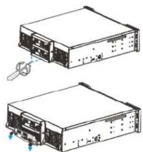
- Remove the RAID controller from the enclosure.
a. Loosen the screws under the two ejection levers.
b. Push the ejection levers downwards to release the controller from the module slot. The controller should slide out easily.
-
Place the controller on a clean, static-free surface. Take care to hold the controller only by its metal canister and avoid touching the circuit board or connector pins.
-
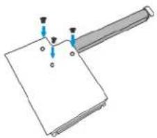
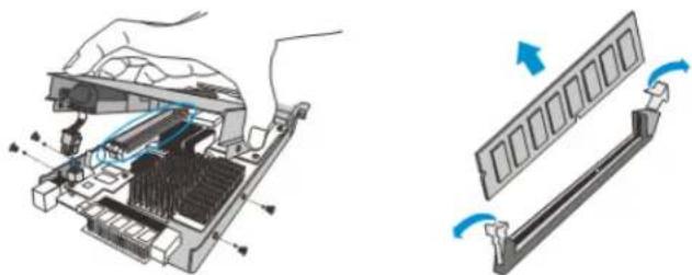
Remove the four screws located on the sides of the controller, and then remove the top cover.
-
Attach the backup battery unit to the underside of the top cover using three screws.
natural_image
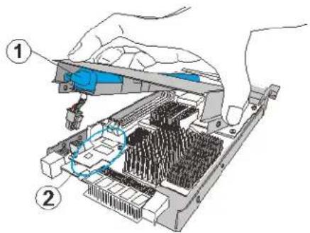
Pure diagram of a mechanical component with no text, numbers, or symbols-
Insert the back end of the battery backup unit into the controller (1), and then connect the backup battery unit power cable to the appropriate receptacle on the controller (2).
-
Secure the cover to the controller using the four screws removed previously (3).
-
Replace the controller in the enclosure.
a. Slide the controller into the empty module slot until you start to feel the contact resistance, use slightly more force and then push the two ejection levers upwards.
b. Tighten the retention screws under the ejection levers to secure the controller in place.
natural_image
Technical line drawing of two electronic device units with ports and connectors, no visible text or symbols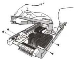
natural_image
Diagram of a computer RAM module with internal components and connectors (no text or labels)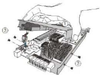
Note
A new or replaced battery backup unit takes at least 12 hours to charge to its full capacity. Follow the procedures in Replacing Cache Backup Modules on page 68 to replace a faulty battery backup unit with a new one in order to maintain fault-tolerant features.
Rack Mounting the Enclosure
If you plan to rack mount the system, you should do this before installing the hard drive(s).
To install a RAID or JBOD enclosure into a rack
- Determine where in the rack you want to install the enclosure. The rail location will vary depending on the size of the enclosure you are installing (2U, 3U, or 4U). The following illustration shows the correct positioning.
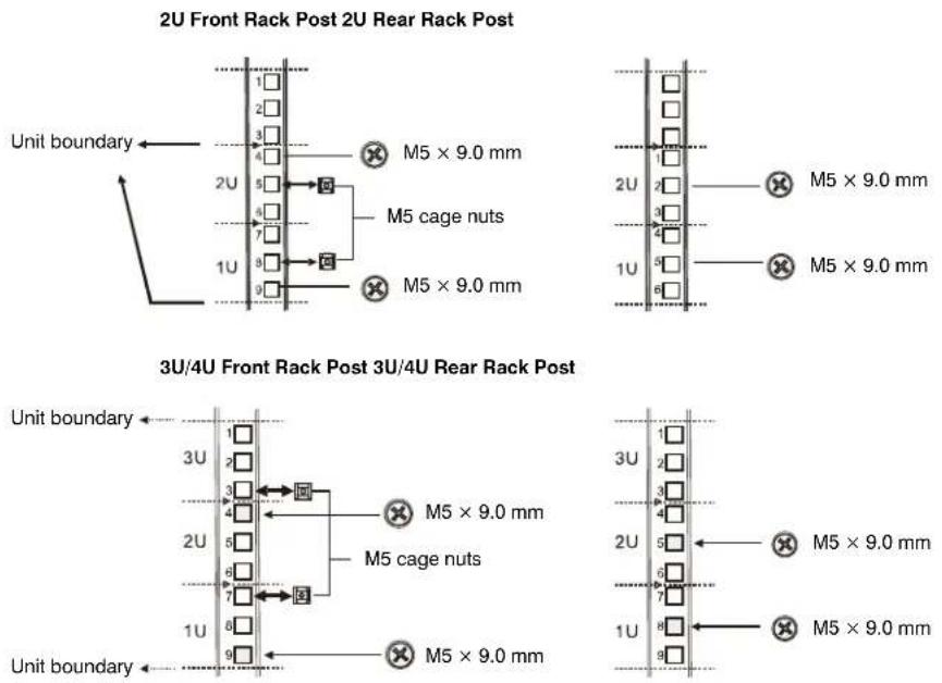
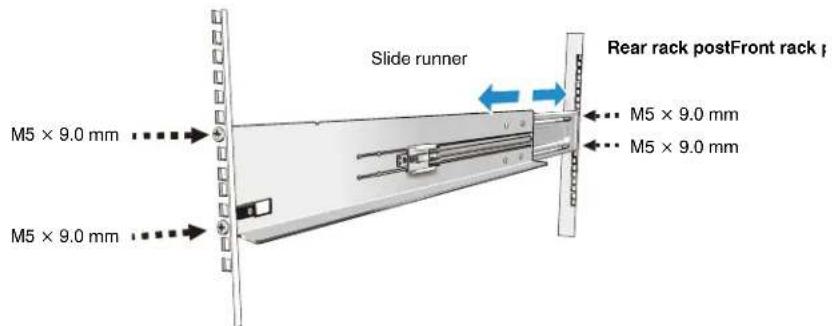
- For each rail, loosen the four retention screws securing the front and rear sections of the rail, and then adjust the rail length to match the distance between the front and rear rack posts.
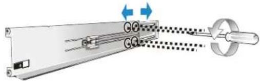
natural_image
Mechanical assembly diagram showing a rotating shaft connected to a circular component with directional arrows indicating motion (no text or symbols)- Attach the left and right rails to the front and rear rack posts using the supplied M5 truss head screws and nuts at the locations shown below.
-
Tighten the retention screws that were loosened in step 2.
-
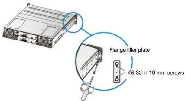
Attach the flange filler plates to the backs of the enclosure ears.
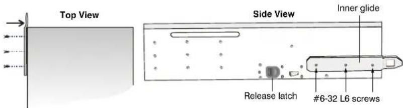
- Attach the inner glides to the sides of the enclosure using the supplied #6-32 L6 flat head screws. Ensure that the part of the glide that extends past the end of the enclosure bends inward (see top view below).
-
Slide the enclosure into the rack. To prevent injury, two people are required for this task.
-
Attach the enclosure to the front rack posts using the supplied M5, M6, or #10-32 screws.
Installing Hard Drives
Before you begin installing the hard drives, do the following:
• Purchase SAS hard drives. See Hard Drive Specifications for details.
- Purchase the necessary cabling to connect the system to the hosts. For sample topologies and configuration options, see Chapter 3, System Connection. For a list of compatible cables, contact your system vendor.
- Cables must be handled with care and must not be bent. To prevent emission interference within a rack system and accidental cable disconnection, the routing paths must be carefully planned.
- Ensure that you are aware of the related positions of each plug-in module and interface connector.
- If you want to change the pre-installed memory module, refer to the replacement procedures in Replacing Memory Modules, page 67.
Hard Drive Specifications
The system uses SAS (3 Gbps or 6 Gbps) 3.5-inch hard drives. Since the maximum capacity used in each drive for composing a RAID array is the maximum capacity of the smallest drive, large storage capacity hard drives are recommended.
You should try to use hard drives with the same capacity. Even hard drives by the same manufacturer, of the same model, and claiming the same rated capacity, may actually carry different block numbers meaning that their capacity may not be exactly the same.
Note When configuring hard drives into a RAID array, you may use a slightly smaller capacity as the "Maximum Disk Capacity" in each individual hard drive.
SAS Interfaces
The following illustration shows a dual-port SAS interface.
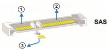
The SAS interface features dual-ported connectivity with pins on both sides of its connector. The SAS interface includes SAS primary links (1), a power link (2), and SAS secondary links (3).
Installing a Hard Drive
The hard drives and drive trays should only be installed after rack mounting is complete. If the hard drives are installed first, the system will be too heavy to handle and the possible impact during installation may damage the hard drives.
Handle hard drives with extreme care and observe all ESD precautions when installing the drives. Only use screws supplied with the system package as longer screws may damage the drive.
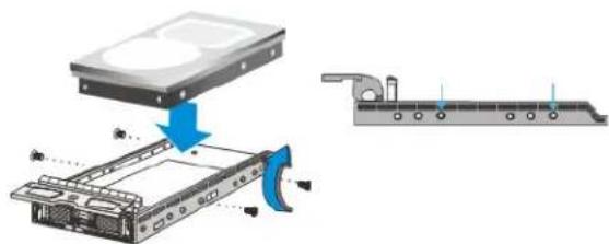
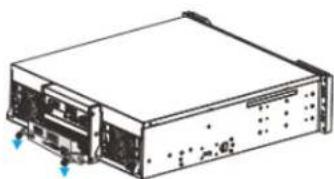
To install a hard drive
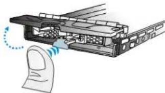
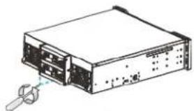
- Press the release button to open the bezel, and gently pull the drive tray out of the enclosure.
natural_image
Diagram of a device with a finger pressing a button, showing no text or symbols-
Place the hard drive in the drive tray with the label facing up, making sure that the interface connector is facing towards the back of the tray.
-
Adjust the location of the hard drive until the mounting holes on the hard drive are aligned with those on the drive tray, and then secure the hard drive to the drive tray with the four supplied screws.
-
Replace the drive tray in the enclosure.
natural_image
Diagram showing a device's internal structure and assembly, with no visible text or symbols.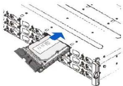
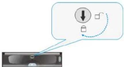
- When the drive tray is fully inserted, close the front bezel and use a small flat-blade screwdriver to turn the bezel lock from unlock to the lock position.
flowchart
graph TD
    A["Download Icon"] --> B["Feedback Loop"]
    B --> C["Device Icon"]
CAUTION Each drive bay must be populated with a tray even if it does not contain a hard drive. If a bay is left empty, ventilation will be disrupted and the system will overheat.
3
System Connection
This chapter contains the following sections:
• System Connection Overview, page 37
• SAS-Host RAID Connections, page 41
• JBOD Connections, page 43
• Management Console Connections, page 46
• Power Connections, page 47
System Connection Overview
This chapter outlines the general configuration rules you should follow when connecting a storage system and provides basic information about topologies. You can use these topologies or refer to them as a guide for developing your own unique topologies.
Preliminary Considerations
When selecting the number of hard drives to be included in a logical drive, the host channel bandwidth and the mechanical performance of individual disk drives should be considered.
It is a good practice to calculate performance against the host port bandwidth when designing an application topology. As an example, if eight members are included in a logical drive and this logical drive is associated with a host ID (LUN mapping), the combined performance of this logical drive should approximate the channel bandwidth. If, for example, two 6-drive logical arrays are associated with two IDs residing on a single host channel, there may be a trade off with performance.
Also consider the following:
- A spare drive carries no data stripes and will not contribute to disk-level performance. Refer to the documentation for your hard drives for performance data.
- When cabling, follow all the specifications. Pay attention to signal quality and avoid electronic noise from adjacent interfaces; for example, do not lay power cords on optical cables.
- The disk drives in the same logical array should have the same capacity, but it is preferred that all the drives within a chassis have the same capacity.
- Disk drives in the same logical drive should have the same capacity, but it is preferred that all the disk drives within a chassis have the same capacity.
- A spare drive should have a minimum capacity that is equivalent to the largest drive that it is expected to replace. If the capacity of the spare is less than the capacity of the drive it is expected to replace, the controller will not proceed with the failed drive rebuild.
- When rackmounting a system, leave enough slack in the cables so that they do not bend to a diameter of less than 3 inches (76 mm).
- Route the cables away from places where it can be damaged by other devices, foot traffic, or fan exhaust.
- Do not over-tighten or bend the cables.
Host-Side Topologies
The primary concern for configuring host-side topologies is to avoid points of failure. It is therefore recommended that the host ports be connected to at least two host bus adapters. It is also preferable to apply corresponding host port type switches (for example, use Fibre Channel switches for Fibre Channel host ports).
Note In order to manage the fault-tolerant data paths and to optimize data throughput on multiple data paths, it is necessary to apply multi-pathing software or utilities such as Linux Device Mapper.
Host-Side Parameters
It is strongly recommended that you use your system's default settings. Should you feel the need to adjust your host-side parameters, please consult on-site technical personnel or technical support.
Maximum Concurrent Host LUN Connection ("Nexus" in SCSI)
The "Max Number of Concurrent Host-LUN Connection" menu option is used to set the maximum number of concurrent host-LUN connections.
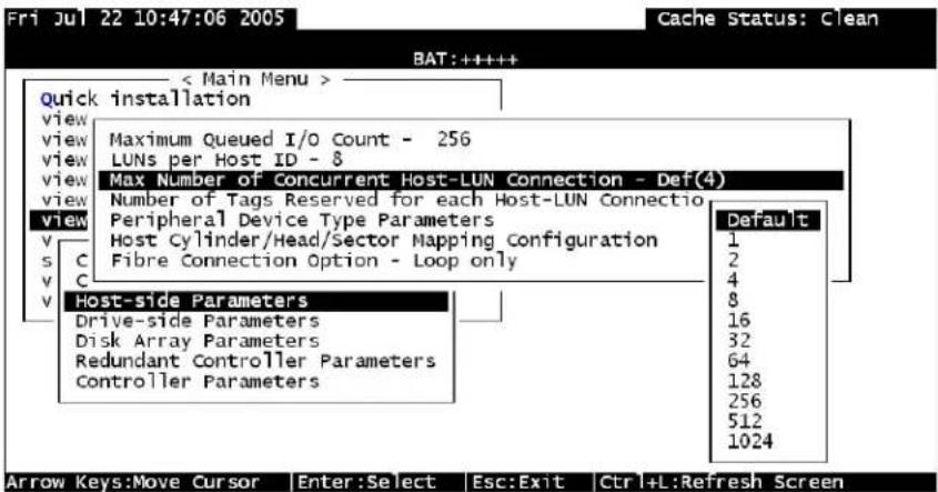
Maximum concurrent host LUN connection ("nexus" in SCSI) is the arrangement of the controller internal resources for use with a number of the current host nexus.
For example, you can have four hosts (A, B, C, and D) and four host IDs/LUNs (IDs 0, 1, 2, and 3) in a configuration where:
- Host A accesses ID 0 (one nexus).
- Host B accesses ID 1 (one nexus).
- Host C accesses ID 2 (one nexus).
- Host D accesses ID 3 (one nexus).
These connections are all queued in the cache and are called four nexus.
If there is I/O in the cache with four different nexuses, and another host I/O comes with a nexus different than the four in the cache (for example, host A accesses ID 3), the controller returns busy. This occurs with the concurrent active nexus. If the cache is cleared, it accepts four different nexuses again. Many I/O operations can be accessed via the same nexus.
Maximum Queued I/O Count
The "Maximum Queued I/O Count" menu option enables you to configure the maximum number of I/O operations per host channel that can be accepted from servers. The predefined range is from 1 to 1024 I/O operations per host channel, or you can choose the "Auto" (automatically configured) setting. The default value is 256 I/O operations.
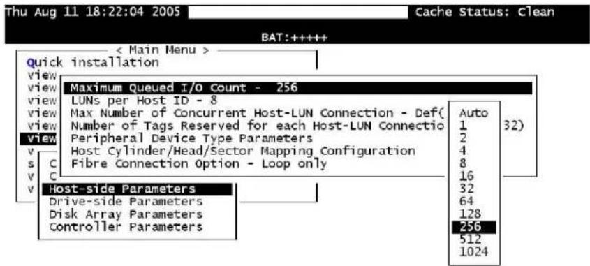
Arrow Keys:Move Cursor Enter:Select Esc:Exit Ctrl+L:Refresh Screen
The appropriate "Maximum Queued I/O Count" setting depends on how many I/O operations the attached servers are performing. This can vary according to the amount of host memory present as well as the number of drives and their size. But optimum performance usually results from using the "Auto" or "256" settings.
SAS-Host RAID Connections
One SFF-8088-to-SFF-8088 host link cable is included per controller. Contact your system vendor if you want to purchase additional cables.
The cables (28 AWG × 8 pairs) are 100-ohm, UL-approved, and lead-free, and come in 20 in. (50 cm), 47 in. (120 cm), or 67 in. (170 cm) cable lengths. Connectors can be secured to enclosure receptacle using thumb screws or a latching mechanism.
Note SAS cables are sensitive and must be handled with care. To prevent interference within a rack system, the cable routing path must be carefully planned and the cables must not be bent.
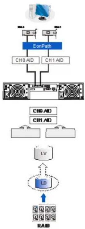
DAS (Direct-Attached Storage) Connection with Redundant Host Path
flowchart
graph TD
    A["Computer"] --> B["EonPath"]
    B --> C["CH0 AID"]
    B --> D["CH1 AID"]
    C --> E["Server"]
    D --> E
    E --> F["LV"]
    F --> G["LD"]
    G --> H["RAD"]
    style A fill:#f9f,stroke:#333
    style H fill:#bbf,stroke:#333
With more hard drives over the SAS expansion links, you can create more logical groups of drives. Multi-pathing software or Linux Device Mapper is necessary for controlling and optimizing the access to logical drives via multiple data paths.
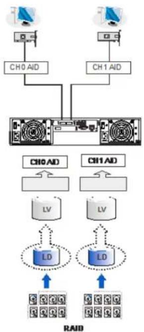
DAS (Direct-Attached Storage) Connection to Two Servers
flowchart
graph TD
    A["CH0 AID"] --> B["Server"]
    C["CH1 AID"] --> B
    B --> D["RD"]
    B --> E["LD"]
    D --> F["RAID"]
    E --> F
    style A fill:#f9f,stroke:#333
    style C fill:#f9f,stroke:#333
    style B fill:#ccf,stroke:#333
    style D fill:#cff,stroke:#333
    style E fill:#cff,stroke:#333
    style F fill:#ffc,stroke:#333
Note If you would like a LUN (a logical partition) to be accessed by multiple hosts, file locking or multi-pathing access control is required.
JBOD Connections
SAS host link cables are included with JBOD systems. If you need to purchase additional cables or if you need cables of a different length, contact your system vendor.
The cables (28 AWG × 8 pairs) are 100-ohm, UL-approved, and lead-free, and come in 20 in. (50 cm), 47 in. (120 cm), or 67 in. (170 cm) cable lengths. Connectors can be secured to enclosure receptacle using thumb screws or a latching mechanism.
Note SAS cables are sensitive and must be handled with care. To prevent interference within a rack system, the cable routing path must be carefully planned and the cables must not be bent.
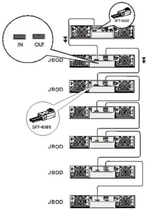
JBOD SAS Expansion Configuration
The SAS expansion port connects to expansion JBOD enclosures. Single controller RAIDs connect to single controller JBODs. A longer cable is required if connections to JBODs are made from two opposite directions. Routing through two different connections can avoid loss of data links if one enclosure fails in between.
There is a rotary ID switch on every expansion enclosure that can be manually configured using a flat blade screwdriver. The configurable IDs for JBODs are from 1 to 15. Numbering normally starts from the JBOD closest to the managing RAID enclosure. Make sure a unique ID is configured on each JBOD so that the SAS WWN addresses of disk drives can be properly assigned. RAID system firmware automatically manages these addresses.
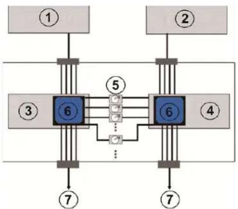
Configuration Rules
Follow these rules when connecting SAS interfaces across RAID and JBOD enclosures:
- With data paths through separate SAS domains, access to disk drives can be continued in the event of a cable link or SAS JBOD controller failure.
flowchart
graph TD
    A["①"] --> B["6"]
    C["②"] --> D["6"]
    E["③"] --> F["6"]
    G["④"] --> H["6"]
    I["⑦"] --> J["7"]
    B --> K["5"]
    D --> L["5"]
    F --> M["..."]
    H --> N["..."]
    J --> O["7"]
    style B fill:#4CAF50,stroke:#388E3C
    style D fill:#4CAF50,stroke:#388E3C
    style F fill:#4CAF50,stroke:#388E3C
    style H fill:#4CAF50,stroke:#388E3C
    style I fill:#4CAF50,stroke:#388E3C
    style J fill:#4CAF50,stroke:#388E3C
    style K fill:#FFA500,stroke:#388E3C
    style L fill:#FFA500,stroke:#388E3C
    style M fill:#FFA500,stroke:#388E3C
    style N fill:#FFA500,stroke:#388E3C
1 RAID Controller A
2 RAID Controller B
3 JBOD Controller A
4 JBOD Controller B
5 Dual-Ported SAS Drives
6 Expander
7 To other JBODs
- SAS expansion cables are available for JBODs. If many JBODs are connected, a longer SAS external cable may be necessary to connect a JBOD from the opposite direction offering high redundancy.
- One expansion link connects JBODs from RAID to the nearest JBOD, and then to the farthest JBOD. Another expansion link connects to the farthest JBOD from the opposite direction and then to the nearest JBOD.
- Each expander controller on the SAS JBOD controls a "SAS Domain" that connects one of the alternative interfaces on all of the disk drives in the enclosure. For example, one expander unit controls Domain A, and the other controls Domain B. In a fault-tolerant topology, the SAS external links always connect to the SAS ports on the same SAS domain.
- The SAS domains can be identified by the expanders' locations (for example, Controller A/Slot A, Controller B/Slot B).
- On the RAID system, each RAID controller can be considered as managing a separate SAS domain.
JBOD Expansion Connections
flowchart
graph TD
    A["IN"] --> B["JBOD"]
    C["OUT"] --> B
    B --> D["SFF-8038"]
    B --> E["SFF-8088"]
    D --> F["Output"]
    E --> F
    F --> G["Output"]
The maximum number of JBOD units that can be controlled by a single controller SAS RAID system through the SAS expansion port is 14.
| RAID System | Max. Number of Drives | Max. Number of 2U JBOD Units | Max. Number of 3U JBOD Units |
| 2U (12-Bay) 312 14 | |||
| 3U (16-Bay) 316 14 | |||
| 4U (24-Bay) 324 14 |
Management Console Connections
flowchart
graph TD
    A["1"] --> B["2"]
    B --> C["3"]
    C --> D["4"]
    D --> E["5"]
    style A fill:#f9f,stroke:#333
    style B fill:#ccf,stroke:#333
    style C fill:#cfc,stroke:#333
    style D fill:#fcc,stroke:#333
    style E fill:#cff,stroke:#333
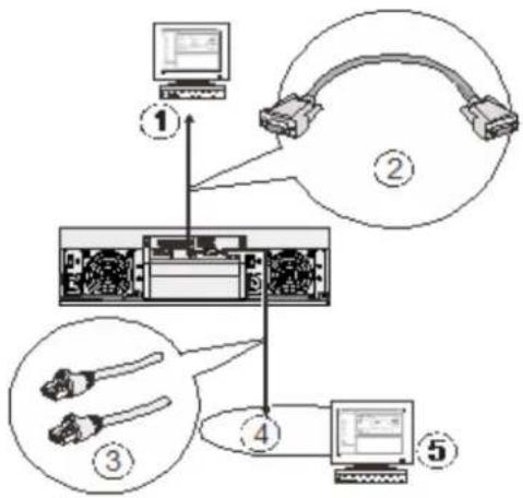
1 Serial Port (for Telnet Access)
4 Local Area Network
2 DB9 Serial
5 SANWatch/Telnet Console
3 CAT5e LAN Cable
When connecting the RAID system to external consoles, note the following:
- Serial port: A standard DB9 straight cable should be supplied by the user (null modem may be required if you are using a third-party cable).
• LAN port: A LAN cable should be supplied by the user.
The serial port's default settings are as follows:
Baud rate: 38400
Data bit: 8
Parity: None
Stop bit: 1
Flow control: Hardware
If your network environment is not running DHCP server protocols, a default IP (10.10.1.1) can be used to access for the first time.
Power Connections
After all of the hard drives have been properly installed and the I/O ports or management interfaces have been connected, the system can be powered on.
Before powering on the system, check that:
- The cache backup module has been properly installed.
• The hard drives are correctly installed in the drive trays. - All the drive trays, whether or not they contain a hard drive, have been installed into the system.
- The system has been correctly connected to host computer(s), management computers, or external networking devices.
- All system components have been acclimated to the surrounding temperature.
Connecting Power Cords
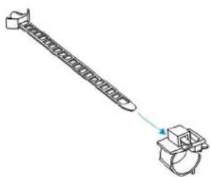
Make sure you that you use the power cables provided. DO NOT use extension cables. The power cables are designed to connect ONLY and DIRECTLY to relocatable power taps (RPTs) on the server cabinet. Use the included cable clamps to secure the power cord connection.
To connect a power cord
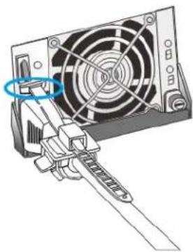
- Attach the cable strap to the cable clamp.
natural_image
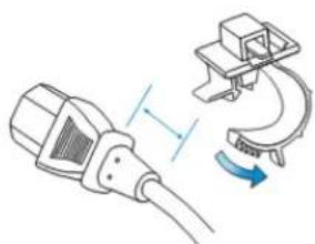
Diagram of a mechanical device with a spring and housing, no text or symbols present- Attach cable clamp to the power cord by opening the clamp and wrapping it around the base of power cord.
natural_image
Illustration of a cable connector with a separate clamp mechanism (no text or symbols)- Adjust the position of cable strap using the release tab.
natural_image
Mechanical assembly diagram showing a lever mechanism with directional arrows (no text or labels)- Position it so that when a power plug is connected to system power the barb anchor can be inserted into the anchor hole above the power socket.
natural_image
Diagram of a computer power adapter with fan and screwdriver (no text or symbols)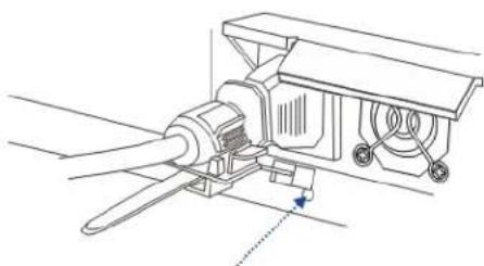
natural_image
Technical line drawing of a mechanical assembly with no visible text or symbols4U RAID Models
2U and 3U RAID Models
Powering On the System
Before you turn on the RAID system, turn on the expansion JBOD storage systems first if your network configuration has multiple arrays.
To power on the system
- Turn on the power switch for every power supply unit in the system, from left to right.
- Turn on the networking devices.
- Turn on the host computers. The host computers should be the last devices that are turned on.
Status Check
After turning on the RAID system, verify the system status by checking the LEDs on the front and rear panels. For more information, see Chapter 4, System Monitoring.
The LED on the LCD keypad panel should illuminate after a successful initialization process, indicating that system status is ready. System initialization and the power-on self-test may take up to five minutes, during which time the system fault LED may be lit. The system fault LED will turn off when the boot-up process is complete.
While powering on the RAID system, wait for the front panel LCD screen to show "READY" or "No Host LUN."
The LCD screen startup sequence is described below:
Initializing... This screen appears when the PSUs are turned on. Please Wait...
Power On Self Test System is performing a self-test. Please Wait...
Power On Init Completed System power on self-test is complete.
ENT RAID vX.XX System is accessing various interfaces.
ENT RAID vX.XX Verifying installed memory. xGB RAM, Wait...
ENT RAID vX.XX System is ready. You can begin configuring the system.
ENT RAID vX.XX System is ready for I/Os. Ready
Power Off the System
Before you turn off the RAID system, make sure no time-consuming processes (like "Regenerate Logical Drive Parity" or "Media Scan") are taking place.
To power off the system
- Close applications running on the host computers to stop all I/O access to the system.
- Flush the cache, if applicable.
a. Check the C_Dirty LED on the controller module. It will be lit amber if there is cached data in the DRAM.
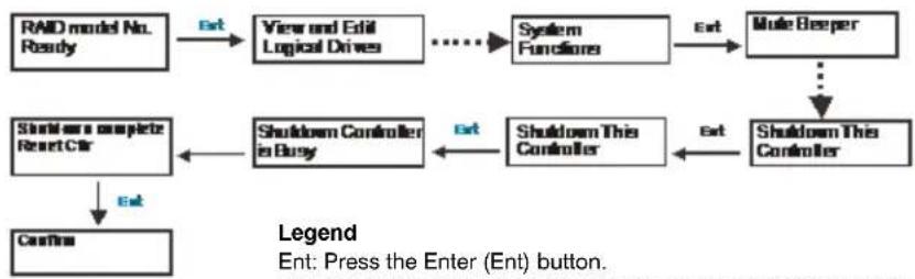
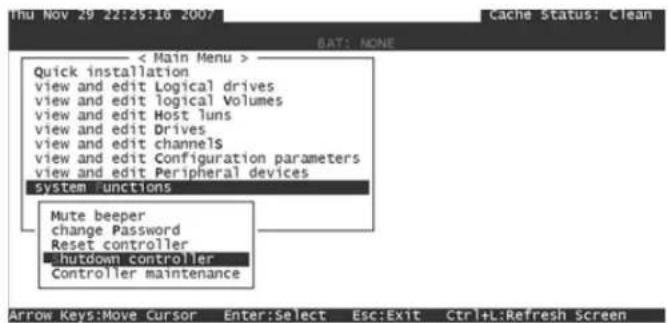
b. Use the Shutdown Controller function to flush all cached data. This prepares the RAID system to be safely powered down.
flowchart
graph TD
    A["RAID model No. Ready"] -->|Ext| B["View and Edit Logical Drives"]
    B --> C["..."]
    C --> D["System Functions"]
    D -->|Ext| E["Mute Beeper"]
    E --> F["..."]
    F --> G["Shutdown This Controller"]
    G -->|Ext| H["Shutdown This Controller"]
    H --> I["Shutdown This Controller"]
    I --> J["Shutdown Controller in Busy"]
    J --> K["Shutdown a complete Reset Ctr"]
    K --> L["Confirm"]
    style A fill:#f9f,stroke:#333
    style E fill:#ccf,stroke:#333
    style G fill:#cfc,stroke:#333
    style H fill:#fcc,stroke:#333
    style I fill:#cff,stroke:#333
    style J fill:#ffc,stroke:#333
    style K fill:#cfc,stroke:#333
    style L fill:#fcc,stroke:#333
---->: Press the up or down arrow to scroll to the desired menu.
- Turn off the power switch for every power supply unit in the system.
System Monitoring
This chapter contains the following sections:
• System Monitoring Overview, page 51
• Monitoring Front Panel Components, page 52
• Monitoring Rear Panel Components, page 55
• Alarms and I2C Bus, page 61
• Restoring Default System Settings, page 62
System Monitoring Overview
There are a three main ways a system manager can monitor the status of a RAID or JBOD system:
- Firmware: The RAID controller is managed by pre-installed firmware that is accessible in a terminal program via the serial port.
- LEDs: LED indicators notify users of system status, events, and failures. LEDs are located on both the front and rear panel of the enclosure.
- Audible alarms: An audible alarm is triggered in the case of system failures.
Monitoring Front Panel Components
LCD Keypad (RAID Models)
The LCD keypad on RAID systems consists of five buttons, three LEDs, and a 16×2-character LCD screen that provides access to the embedded firmware utility.
Name Description
- ESC Button Press ESC to skip the current event or return to the previous menu level.
- UP Button Press the up arrow to navigate through menu options.
- DOWN Button Press the down arrow to navigate through menu options.
- ENT Button Press ENT to browse events. To see a detailed description of each event, use the up or down buttons to select the event, then press and hold down ENT until a short beep is heard, then use the up or down buttons to browse through the description lines. To delete the event, tap ENT lightly.
- Mute Button Press MUTE to silence the alarm until the next event occurs.
LCD Panel LED Definitions (RAID Models)
LED Name Color Status
-
PWR (Power) Blue BLUE indicates that power has been turned on and the system status is normal. OFF indicates that no power is supplied to the system or the RAID system has failed.
-
BUSY White FLASHING WHITE indicates that there is active traffic on the host/drive channels. OFF indicates that there is no activity on the host/drive channels.
-
ATTEN (Attention) Red RED indicates that a component failure/ status event has occurred. OFF indicates that the system and all its components are in proper operation status.
Chassis Ear LED Definitions (JBOD Models)
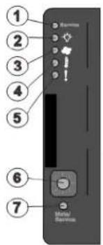
1 Service LED
2 Power Supply Status LED
3 Cooling Module Status LED
4 Temperature Sensor Status LED
5 System Fault Status LED
| LED Name Color Status | |
| 1. Service White WHITE indicates that the system is being serviced or is requiring services.OFF indicates that the system is not being serviced nor is requiring services. | |
| 2. Power Green/Amber GREEN indicates that the system is powered properly.AMBER indicates that there is a power failure in the system. | |
| 3. Cooling Fan Green/Amber GREEN indicates that the cooling fan is operating properly.AMBER indicates that there is a cooling fan failure in the system. | |
| 4. Thermal Green/Amber GREEN indicates that the internal temperature is within the safety threshold.AMBER indicates that the internal temperature has exceeded the safety threshold. | |
| 5. System Fault Green/Amber GREEN indicates that the system is operating normally.AMBER indicates that the system has encountered abnormal conditions. |
CAUTION If critical faults are indicated on the LED panel, verify the cause of the problem as soon as possible and contact your system vendor to arrange for a replacement module.
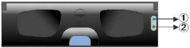
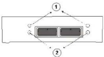
Drive Tray LED Definitions
Two LED indicators are located on the right side of each drive tray. When notified by a drive failure message, you should check the drive tray indicators to find the correct location of the failed drive.
natural_image
Diagram of a vehicle front view with two labeled components (① and ②), no readable text or symbols present.LED Name Color Status
-
Drive Busy Blue FLASHING BLUE indicates that the drive is busy (data is being written to or read from the drive). OFF indicates that there is no activity on the disk drive.
-
Power Green/Red GREEN indicates that the drive bay is populated and is working normally. RED indicates that the disk drive has failed or a connection problem has occurred.
Monitoring Rear Panel Components
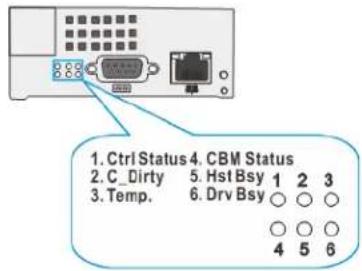
Controller LED Definitions (RAID Models)
LED Name Color Status
- Ctrl Status Green/Amber GREEN indicates that a RAID controller is operating healthily.
AMBER indicates that a component failure has occurred, or inappropriate RAID configurations have caused system faults. It is also lit during the initialization process.
-
C_Dirty Amber AMBER indicates the following:
-
Cache memory is dirty.
- Data in flash backup module is being flushed to cache.
- Errors occurred with cache memory (ECC error).
- Data is being flushed from flash backup module to drive (when power is restored).
- Battery voltage is lower than 2.5 V.
- Battery temperature reading is abnormal.
- Battery is not present.
FLASHING AMBER indicates cached data is being transferred to the flash module after a power outage. Once the transfer is done, all LEDs turn off.
OFF indicates that the cache is clean, and that the battery backup unit is capable of sustaining memory in case of power loss.
This signal is local to each controller.
- Temp. Amber AMBER indicates that the detected CPU/board/
enclosure temperature has exceeded the high temperature threshold.
OFF indicates that the detected temperature reading is within the safe range.
- CBM Status Green/Amber GREEN indicates the cache backup module is ready.
Both BBU and FBM are present.
AMBER indicates CBM failure, meaning either BBU or FBM has failed.
FLASHING AMBER indicates BBU being charged.
OFF means BBU is not installed in a single-controller "G" model.
-
Hst Bsy Green FLASHING GREEN indicates traffic on the host bus.
-
Drv Bsy Green FLASHING GREEN indicates traffic on the drive channels.
-
Restore Default Green GREEN indicates RAID configuration default successfully restored. The LED turns off after a few seconds.
Controller LED Definitions (JBOD Models)
flowchart
graph TD
    A["①"] --> B["②"]
    B --> C["③"]
    style A fill:#000,stroke:#000,color:#fff
    style B fill:#000,stroke:#000,color:#fff
    style C fill:#000,stroke:#000,color:#fff
LED Name Color Status
-
SAS Link Green SOLID GREEN indicates all 4 PHYs are validly linked to external devices. FLASHING GREEN indicates one of the 4 PHYs links has failed. OFF indicates all 4 PHYs are offline.
-
SAS Speed Green/Amber GREEN indicates 6 Gbps link speed. AMBER indicates 3 Gbps link speed. OFF indicates connection not established.
-
Ctrl Status Green/Amber GREEN indicates the controller is operating normally. AMBER indicates a component failure has occurred. It is also lit during the initialization process.
Ethernet Management Port LEDs
Type I
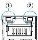
LED Name Color Status
-
Speed Green GREEN indicates 100 Mbps connection. OFF indicates 10 Mbps or slower connection established.
-
Link/Activity Green SOLID GREEN indicates connection established. FLASHING GREEN indicates data activity. OFF indicates connection not established.
Type II
LED Name Color Status
- Speed Green GREEN indicates 1 Gbps connection.
OFF indicates 10/100 Mbps or slower connection established. - Link/Activity Amber SOLID AMBER indicates connection established.
FLASHING AMBER indicates data input/output.
OFF indicates connection not established.
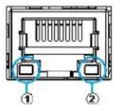
SAS-Host Port LEDs
flowchart
graph TD
    A["Component ①"] --> B["Component ②"]
    B --> A
    style A fill:#f9f,stroke:#333
    style B fill:#bbf,stroke:#333
LED Name Color Status
-
SAS Link Green SOLID GREEN indicates all 4 PHYs are validly
linked to external devices.
FLASHING GREEN indicates less than 4 PHY
links are connected.
OFF indicates that all 4 PHYs are offline. -
SAS Speed Green/Amber GREEN indicates a 6 Gbps connection.
AMBER indicates a 3 Gbps connection.
OFF indicates connection not established.
Power Supply Unit/Cooling Module LED Definitions
The power supply unit (PSU) contains the LEDs for the PSU and the cooling module statuses. When either of the unit fails, you need to replace the PSU as soon as possible. For details, please refer to Replacing Power Supply Units, page 70.
2U/3U Power Supply Unit/Cooling Module LEDs
1. Power Supply Unit LED
| LED State Color Description |
| Flashing Green The system is connected to the power sourcebut the power switch is not turned on. |
| Solid Green The PSU is operating normally. |
| Solid Red The PSU has failed and is unable to supplypower to the system. |
2. Cooling Fan LEDs
| LED State Color Description |
| Off N/A The cooling fan is operating normally. |
| Solid Red The cooling fan has failed. |
4U RAID Power Supply Unit LED
LED State Color Description
| Flashing Green The system is connected to the power sourcebut the power switch is not turned on. |
| Solid Green The PSU is operating normally. |
| Solid Red The PSU has failed and is unable to supplypower to the system. |
| Off N/A The PSU is not turned on and the power cord isdisconnected. |
4U RAID Cooling Module LED
LED State Color Description
| Off N/A The cooling fan is operating normally. |
| Solid Red The cooling fan has failed. |
Alarms and I²C Bus
Alarms
If any of the following components fails, an audible alarm is triggered:
- Cooling fan module
- Power supply unit
- Cache backup module
- Hard disk drives
- Sensors or presence detection circuitries
When you hear an alarm, read the error message on the terminal to determine what triggered the alarm, and then take appropriate action to correct the problem. The alarm can be turned off using the mute button on the front panel.
The operating status of the power supply unit and cooling fan modules are collected through an I^2C serial bus. If either of those modules fails, you will be notified by an audible alarm and an error message on the terminal.
Restoring Default System Settings
You may need to restore default system settings when the firmware update procedure requires it or when you need to reset the password to access the RAID system. Restoring default settings is a last-resort function as all configurations, such as parameters and host LUN mappings, will be erased.
To restore default settings
- Stop all host I/Os.
- Save the current configuration using the "Export NVRAM" function on the LCD panel.
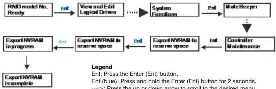
flowchart
graph TD
    A["RAID model No. Ready"] -->|Ent| B["View and Edit Logical Drives"]
    B --> C["...."]
    C --> D["System Functions"]
    D -->|Ent| E["Mute Beeper"]
    E --> F["..."]
    F --> G["Controller Maintenance"]
    G --> H["Export NVRAM to reserve space"]
    H --> I["Export NVRAM in progress"]
    I --> J["Export NVRAM is complete"]
    style A fill:#f9f,stroke:#333
    style B fill:#ccf,stroke:#333
    style C fill:#cfc,stroke:#333
    style D fill:#fcc,stroke:#333
    style E fill:#cff,stroke:#333
    style F fill:#ffc,stroke:#333
    style G fill:#cfc,stroke:#333
    style H fill:#fcc,stroke:#333
    style I fill:#cfc,stroke:#333
    style J fill:#fcc,stroke:#333
    style_K["Legend\nEnt: Press the Enter (Ent) button.\nEnt (blue): Press and hold the Enter (Ent) button for 2 seconds.\n---->: Press the up or down arrow to scroll to the desired menu."] --> L["End"]
- If you want, make a list of the existing ID/LUN mapping information as the default restoration will erase the ID/LUN mapping associations (for example, which logical drive is associated with which host ID/LUN).
- Remove Controller B from the enclosure.
- Power off the RAID system.
- Press and hold the Restore Default button on Controller A and, while pressing the button, power on the RAID system.
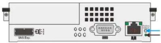
-
When the "Restore Def." LED (indicated by the black arrow) lights up and the "Default Restored" firmware event message appears, release the Restore Default button.
-
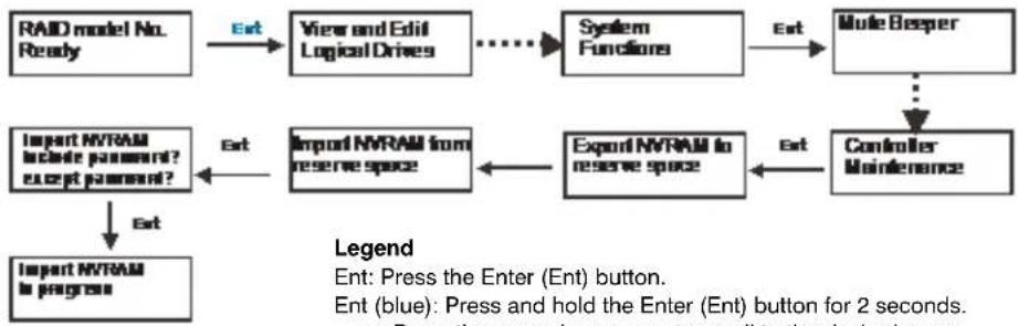
Restore previous settings using the "Import NVRAM from reserve space" or "Restore NVRAM from Files" in the firmware. ID/LUN mapping will be restored.
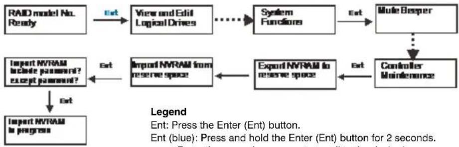
flowchart
graph TD
    A["RAID model No. Ready"] -->|Ext| B["View and Edit Logical Drives"]
    B --> C["System Functions"]
    C -->|Ext| D["Mule Besper"]
    D --> E["Controller Maintenance"]
    E -->|Ext| F["Export NVRAM to reserve space"]
    F --> G["Import NVRAM from reserve space"]
    G -->|Ext| H["Import NVRAM include password? except password?"]
    H --> I["Import NVRAM to progress"]
    style A fill:#f9f,stroke:#333
    style B fill:#ccf,stroke:#333
    style C fill:#cfc,stroke:#333
    style D fill:#fcc,stroke:#333
    style E fill:#cff,stroke:#333
    style F fill:#ffc,stroke:#333
    style G fill:#cfc,stroke:#333
    style H fill:#fcc,stroke:#333
    style I fill:#ffc,stroke:#333
---->: Press the up or down arrow to scroll to the desired menu.
5
System Maintenance
This chapter contains the following sections:
• Replacing Controller Modules, page 65
• Replacing Memory Modules, page 67
• Replacing Cache Backup Modules, page 68
• Replacing Power Supply Units, page 70
• Replacing Cooling Modules, page 72
• Replacing Hard Drives, page 74
Replacing Controller Modules
Use the following procedure to replace a RAID controller module.
Do not mix controller modules from different models. Each controller has a unique ID which is applied to host port names. As the result, you may encounter SAN problems with identical port names on multiple systems.
Before you replace the controller(s), export and save the NVRAM data using the LCD panel, follow the illustration below:
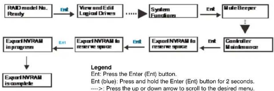
flowchart
graph TD
    A["RAID model No. Ready"] --> B["View and Edit Logical Drives"]
    B --> C["System Functions"]
    C --> D["Mole Beeper"]
    D --> E["Controller Maintenance"]
    E --> F["Export NVRAM to reserve space"]
    F --> G["Export NVRAM in progress"]
    G --> H["Export NVRAM is complete"]
    H --> I["Export NVRAM to reserve space"]
    I --> J["Export NVRAM in progress"]
    style A fill:#f9f,stroke:#333
    style D fill:#ccf,stroke:#333
    style E fill:#cfc,stroke:#333
    style F fill:#fcc,stroke:#333
    style G fill:#cff,stroke:#333
    style H fill:#ffc,stroke:#333
    style I fill:#fcf,stroke:#333
    style J fill:#cff,stroke:#333
To replace a controller
- Prepare a clean, static-free surface on which to place the controller.
- Shut down all system applications.
- Stop all I/O access to the system and make sure all cached writes have been distributed to disk drives using the firmware's Main Menu > System Functions > Shutdown controller function.
- Shut down the system and turn off the power switches and unplug the power cords from the power supply units.
- Disconnect all cables connected to the controller module.
- Loosen the retention screw that secures the controller module's election levers.
natural_image
Illustration of a server rack unit with a cable inserted, showing internal components and no text or symbols.- Push the ejection levers downward. The controller module will automatically ease out of the controller module bay.
natural_image
Diagram of a computer rack unit with ports and connectors (no text or labels)- Insert the new controller module into the module bay. Carefully push the controller until you feel the board edge connectors engage the backplane, and then push the ejection levers upward.
- Tighten the retention screw on the ejection levers.
- Reattach all the cables to the controller module.
- Turn on the system.
-
Check system message on the LCD screen or firmware menu-driven utility and check the Power LEDs. When the replacement controller is successfully brought online, the Power LEDs will appear solid green.
-
Restore the NVRAM data by doing one of the following:
- Use the "Restore NVRAM from Disks" or "Restore NVRAM from Files" function in the firmware to restore ID/LUN mapping. or
- Use the LCD panel to restore ID/LUN mapping settings (refer to the illustration below).
flowchart
graph TD
    A["RAID model No. Ready"] -->|Ext| B["View and Edit Logical Drives"]
    B --> C["System Functions"]
    C -->|Ext| D["Mule Besper"]
    D --> E["Controller Maintenance"]
    E -->|Ext| F["Export NVRAM to reserve space"]
    F --> G["Import NVRAM from reserve space"]
    G --> H["Import NVRAM include password? except password?"]
    H --> I["Import NVRAM to progress"]
    style A fill:#f9f,stroke:#333
    style D fill:#ccf,stroke:#333
    style E fill:#cfc,stroke:#333
    style F fill:#fcc,stroke:#333
    style G fill:#cff,stroke:#333
    style H fill:#ffc,stroke:#333
    style I fill:#cfc,stroke:#333
---->: Press the up or down arrow to scroll to the desired menu.
Replacing Memory Modules
The RAID controller comes with pre-installed dynamic random access memory (DRAM) modules. You can upgrade the memory modules or replace them as necessary. Contact your system vendor for a list of compatible DRAM modules.
Note Reusing a DRAM module removed from a failed controller is not recommended unless you have a similar RAID system to test its integrity.
To replace a dual in-line memory module (DIMM)
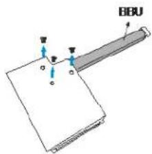
- Remove the controller module (see Replacing Controller Modules, page 65).
- Remove the BBU module (see Replacing Cache Backup Modules, page 68).
natural_image
Diagram showing a computer motherboard with internal components and a memory card slot, no text or symbols present.Removing BBU Module Removing DIMM from Socket
- Wait for one minute for the remaining electricity on the main board to dissipate.
- Push down on the clips on either side of the DIMM socket to eject the DIMM.
- Install the replacement DIMM into the DIMM socket.
a. Make sure the side clips are in the open positions.
b. Align the DIMM with the socket, and then firmly push the DIMM into the socket. The side clips will close automatically and secure the DIMM in the socket.
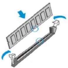
natural_image
Diagram of a mechanical component with rotating arrows indicating motion (no text or symbols)- Reinstall the BBU module (see Replacing Cache Backup Modules, page 68).
- Reinstall the controller module (see Replacing Controller Modules, page 65).
Replacing Cache Backup Modules
The cache backup module (CBM) consists of a battery backup unit (BBU) and a flash backup module (FBM). The CBM can sustain and transfer cached data to a flash backup module in the event of a power outage or in the unlikely event of both PSUs failing. A CBM (BBU+FBM) is optional for single controller systems.
The following components can be upgraded or replaced:
- Battery backup unit: In the event of a power failure, the BBU can help store/save cached data in the DRAM module for up to 72 hours.
- Battery backup unit + flash backup module: In the event of a power failure, the combination of BBU+FBM (non-volatile flash storage) can store data indefinitely.
Note The flash backup module is not user serviceable.
Battery Backup Unit Fault Conditions and Precautions
If a battery backup unit leaks, gives off a bad odor, generates heat, becomes discolored or deformed, or in any way appears abnormal during use, recharging, or storage, immediately remove it from the system and stop using it.
Conditions that could trigger a BBU fault include the following:
- The temperature sensor on the system's charger circuit reports a temperature reading exceeding the pre-set threshold. The charger circuits will enter a low power and self-protection state.
- A BBU module has been charged for over 12 hours. A timer is embedded with the charger. When this occurs, the charger will enter a timer fault state. Charging will resume automatically after you remove/reinstall the BBU module or reset the system.
Follow these precautions when you install a BBU:
- Use the replacement BBU supplied by your distributor. Use of other battery cells will void your warranty.
- Dispose of used BBUs at an authorized battery disposal site only.
- Do not place a BBU near a heat source.
- Do not immerse the BBU in water or expose it to liquids.
- Do not disassemble or modify the BBU.
- Do not pierce the BBU with a sharp object, strike it with a hammer, exert pressure on it, or throw it.
Replacing a Battery Backup Unit
To replace a backup battery unit
- Remove the RAID controller from the enclosure.
a. Loosen the screws under the two ejection levers.
b. Push the ejection levers downwards to release the controller from the module slot. The controller should slide out easily.
-
Place the controller on a clean, static-free surface. Take care to hold the controller only by its metal canister and avoid touching the circuit board or connector pins.
-
Remove the four screws located on the sides of the controller (1), and then remove the top cover.
-
Remove the BBU (2). For type II controller models, unplug the BBU power connector, and then remove the screws securing the BBU to the top cover.
natural_image
Diagram of a server rack unit with a cable inserted, showing internal components and no text or labels.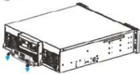
natural_image
Line drawing of a server rack unit with ports and connectors (no text or symbols)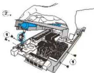
-
Install the replacement BBU. For type II controller models, attach the new backup battery unit to the underside of the top cover using the screws removed in step 4.
-
Insert the back end of the battery backup unit into the controller (1), and then, if applicable, connect the backup battery unit power cable to the controller (2).
- Secure the cover to the controller using the four screws removed previously (3).
- Replace the controller in the enclosure.
a. Slide the controller into the empty module slot until you start to feel the contact resistance, use slightly more force and then push the two ejection levers upwards.
b. Tighten the retention screws under the ejection levers to secure the controller in place.
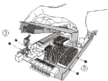
Note
A new or replaced battery backup unit takes at least 12 hours to charge to its full capacity. If the cause of a failure cannot be determined even after the battery backup unit is replaced, contact your system vendor. The life expectancy of a battery backup unit is 3 years.
Replacing Power Supply Units
The power supply units (PSUs) are configured in a redundant configuration with each PSU housed in a robust steel canister.
A problem with a PSU is indicated when the PSU status LEDs change to solid red, an alarm sounds, and a notification message appears in the firmware utility. Although the system can operate with a failed PSU, it is not recommended to run the system with a failed PSU for an extended period of time. The failed redundant PSU should be replaced as soon as possible.
Use the following procedures to replace a failed PSU.
To replace a 2U or 3U power supply unit
- Shut down the system, turn off the PSU/cooling module, and disconnect the power cord.
- Loosen the retention screw that secures the extraction handle to the enclosure (see illustration).
- Remove the PSU/cooling module from the enclosure.
a. Grasp the extraction handle and pull it upwards to disconnect the PSU/cooling module from the backplane connectors.
b. Using your other hand to support its weight, gently pull the PSU/cooling module out of the enclosure.
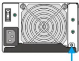
natural_image
Back view of a computer drive with fan and buttons (no text or symbols visible)- Install the replacement PSU/cooling module.
a. Make sure the extraction handle (1) is held at its highest position so that the saddle notches on the sides of the handle can snap onto the metal anchor pins (2) on the interior walls of the PSU slot.
b. Push the PSU/cooling module into the enclosure (3). When you feel the contact resistance, use slightly more t
c. Push the handle downwards to secure the module.
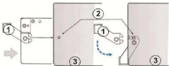
flowchart
graph TD
    A["Step 1"] --> B["Step 2"]
    B --> C["Step 3"]
    C --> D["Step 3"]
    style A fill:#f9f,stroke:#333
    style B fill:#ccf,stroke:#333
    style C fill:#cfc,stroke:#333
    style D fill:#fcc,stroke:#333
-
Tighten the retention screw that secures the extraction handle to the enclosure.
-
Reconnect the power cord and turn on the PSU/cooling module.
To replace a 4U RAID system PSU
- Disconnect the power cord from the failed PSU.
- Loosen the retention screw(s) that secures the extraction handle to the enclosure.
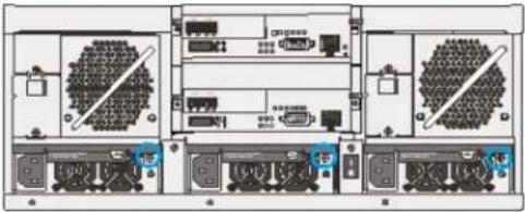
natural_image
Front view diagram of a server rack with multiple ports and connectors (no visible text or labels)- Remove the PSU from the enclosure.
a. Push the extraction handle (1) downwards. The extraction handle should gracefully disconnect the PSU from the backplane connectors.
b. Using your other hand to support its weight, gently pull the PSU out of the enclosure.
- Install the replacement PSU.
a. Make sure the extraction handle (1) is held at its lowest position so that the saddle notches on the sides of the handle can snap onto the metal anchor pins (2) on the interior walls of the PSU slot.
b. Push the PSU into the enclosure.
c. When you feel the contact resistance, pull the handle upwards to secure the PSU.
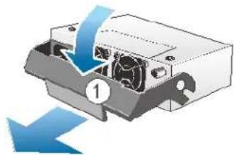
natural_image
Diagram of a computer drive with blue arrows indicating motion, no text or symbols present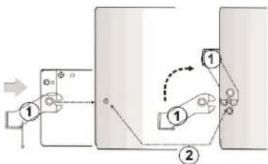
flowchart
graph TD
    A["Step 1"] --> B["Step 2"]
    B --> C["Step 3"]
    C --> D["Step 4"]
    D --> E["Step 5"]
    E --> F["Step 6"]
    F --> G["Step 7"]
    G --> H["Step 8"]
    H --> I["Step 9"]
    I --> J["Step 10"]
    style A fill:#f9f,stroke:#333
    style B fill:#f9f,stroke:#333
    style C fill:#f9f,stroke:#333
    style D fill:#f9f,stroke:#333
    style E fill:#f9f,stroke:#333
    style F fill:#f9f,stroke:#333
    style G fill:#f9f,stroke:#333
    style H fill:#f9f,stroke:#333
    style I fill:#f9f,stroke:#333
    style J fill:#f9f,stroke:#333
- Tighten the retention screw that secures the extraction handle to the enclosure.
- Connect the power cord to the PSU and secure the connection using the supplied cable clamp.
Replacing Cooling Modules
In 2U and 3U RAID systems, the cooling modules are built into the power supply unit (PSU). In 4U systems, the cooling modules may be standalone or built into the PSU.
A problem with the cooling module is indicated when the cooling module status LEDs (located on the module itself) change to solid red, an alarm sounds, and a notification message appears in the firmware utility.
Use the following procedures to replace a faulty cooling module. To prevent prolonged disruption to the system airflow, it is recommended that you complete the cooling module replacement within 5 minutes.
To replace a 2U or 3U cooling module
- Shut down the system, turn off the PSU/cooling module, and disconnect the power cord.
- Loosen the retention screw that secures the extraction handle to the enclosure (see illustration).
- Remove the PSU/cooling module from the enclosure.
a. Grasp the extraction handle and pull it upwards to disconnect the PSU/cooling module from the backplane connectors.
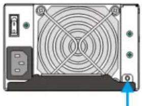
natural_image
Front view of a computer drive with fan and buttons (no text or symbols visible)b. Using your other hand to support its weight, gently pull the PSU/cooling module out of the enclosure.
- Insert the replacement PSU/cooling module.
a. Make sure the extraction handle (1) is held at its highest position so that the saddle notches on the sides of the handle can snap onto the metal anchor pins (2) on the interior walls of the PSU slot.
b. Push the PSU/cooling module into the enclosure (3). When you feel the contact resistance, use slightly more
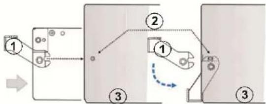
flowchart
graph TD
    A["Step 1"] --> B["Step 2"]
    B --> C["Step 3"]
    C --> D["Step 3"]
    style A fill:#f9f,stroke:#333
    style B fill:#ccf,stroke:#333
    style C fill:#cfc,stroke:#333
    style D fill:#fcc,stroke:#333
c. Push the handle downwards to secure the module.
-
Tighten the retention screw that secures the extraction handle to the enclosure.
-
Reconnect the power cord and turn on the PSU/cooling module.
To replace a 4U RAID system cooling module
- Grasp the cooling module's extraction handle, and then, while pushing the retention latch to the side, pull the module out of the enclosure.
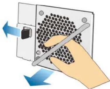
natural_image
Illustration of a hand using a tool to adjust a component with arrows indicating direction (no text or symbols)- Install the replacement module by pushing it gently into the module bay. You may need to push the retention latch sideways (just as when you were removing it) while installing the replacement module. When fully inserted, the retention latch will hold the module in place.
Replacing Hard Drives
Ensure that you have a replacement hard drive on hand before removing a faulty hard drive. Do not leave the drive tray open for an extended period of time or the internal airflow will be disrupted and the system may overheat. Handle hard drives with extreme care. Carry them only by the edges and avoid touching their interface connectors. Observe ESD precautions when replacing hard drives.
To replace a hard drive
- Identify the drive bay you want to access. Use the firmware utility or the LED on the drive tray to identify faulty hard drive(s). The drive bays are numbered from left to right and from top to bottom.
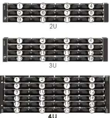
- Unlock the drive tray bezel. Use a small flat-blade screwdriver to turn the bezel lock from lock to the unlock position.
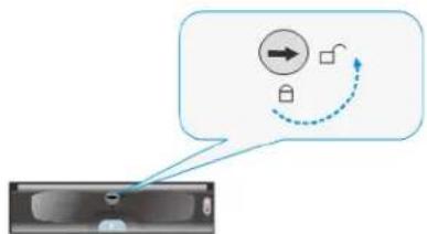
flowchart
graph TD
    A["Input"] --> B{Processing}
    B -->|Yes| C["Output"]
    B -->|No| D["Feedback Loop"]
    D --> E["Output"]
    style A fill:#f9f,stroke:#333
    style E fill:#bbf,stroke:#333
- Press the release button to open the bezel. The spring handle pops out.
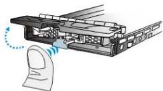
natural_image
Diagram of a mechanical assembly with a finger and a paper clip, showing motion direction (no text or symbols)-
Pull the drive tray out of the enclosure about 1 inch. Wait at least 30 seconds for the disk drive to spin down, and then gently remove the drive tray from the enclosure.
-
Remove the four retention screws securing the hard drive to the drive tray and remove the hard drive.
-
Place the new hard drive in the drive tray and replace the four retention screws.
-
Replace the drive tray in the enclosure.
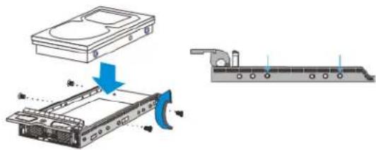
natural_image
Technical illustration of a hard disk drive assembly with a blue arrow indicating motion (no text or symbols present)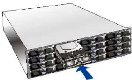
natural_image
3D rendering of a server rack with multiple ports and an arrow pointing to a component (no text or symbols visible)- When the drive tray is fully inserted, close the front bezel and use a small flat-blade screwdriver to turn the bezel lock from unlock to lock position. Do not push the bezel lock when turning the screwdriver or the spring handle will pop out again.
CAUTION Never leave the bezel lock unlocked or the RAID controller may treat it as a faulty drive.
- Ensure that no drive errors are still being reported.
Technical Specifications
| Specification | 12-Bay Subsystems | 16-Bay Subsystems | 24-Bay Subsystems |
| Available Configurations RAID and JBOD - 2U RAID and JBOD - 3U RAID only - 4U | |||
| Voltage | 100-240 VAC auto-ranging | 100-240 VAC auto-ranging | 100-240 VAC auto-ranging |
| Current (maximum, each supply) | 10 A @ 100 VAC or 5 A @ 240 VAC | 10 A @ 100 VAC or 5 A @ 240 VAC | 8 A @ 100 VAC or 4 A @ 240 VAC |
| Power Consumption | Idle: 230 WBusy: 245 W | Idle: 345 WBusy: 367 W | Idle: 409 WBusy: 434 W |
| Power Supply | Dual 530 W, 100-240 VAC auto-ranging, 47-63 Hz, dual hot swap and redundant with PFC, N+1 design | Dual 530 W, 100-240 VAC auto-ranging, 47-63 Hz, dual hot swap and redundant with PFC, N+1 design | Triple 405 W, 100-240 VAC auto-ranging, 50-60 Hz, triple hot swap and redundant with PFC, N+1 design |
| Temperature | 32° to 104°F (0° to 40°C) operational-40° to 140°F (-40° to 60°C) non-operational | ||
| Relative Humidity | 5 to 95% (non-condensing, operating and non-operating) | ||
| Vibration | (Random)Operating: 5 to 500 Hz, 0.25 Grms, X/Y/Z, 30 minNon-operating: 5 to 500 Hz, 1.0 Grms, X/Y/Z, 30 min(Sine)Operating: 5 to 500 Hz, 0.2 Grms, X/Y/Z Sine, 1hr/sweepNon-operating: 5 to 500 Hz, 1.0 Grms, X/Y/Z Sine, 1hr/sweep | ||
| Dimensions (H×W×D) | 3.5 × 17.5 × 20.2 in.(8.8 × 44.6 × 51.4 cm) | 5.1 × 17.5 × 20.2 in.(13.0 × 44.5 × 51.4 cm) | 6.8 × 18.9 × 21.4 in.(17.4 × 48.1 × 54.4 cm) |
| Net Weight | 39.9 lb (18.1 kg) without drives, 53.1 lb (24.1 kg) with 12 drives, assuming 1.1 lb (0.5 kg) per drive | 47.75 lb (21.66 kg) without drives, 65.39 lb (29.66 kg) with 16 drives, assuming 1.1 lb (0.5 kg) per drive | 60.49 lb (27.44 kg) without drives, 86.95 lb (39.44 kg) with 24 drives, assuming 1.1 lb (0.5 kg) per drive |
| Gross Weight (incl. carton) | 66 lb (30 kg) without drives | 82.7 lb (37.5 kg) without drives | 99.2 lb (45 kg) without drives |
| Emissions FCC Subpart 15B, Class A | |||
| Safety | UL/CSA 60950-1 | ||
Honeywell Security Products Americas (Head Office)
2700 Blankenbaker Pkwy, Suite 150
Louisville, KY 40299, USA
www.honeywell.com/security
+1 800 323 4576
Honeywell Security Northern Europe
Ampèrestraat 41
1446 TR Purmerend, The Netherlands
www.honeywell.com/security/nl
+31 (0) 299 410 200
Honeywell Security Europe/South Africa
Aston Fields Road, Whitehouse Industrial Estate
Runcorn, WA7 3DL, United Kingdom
www.honeywell.com/security/uk
+44 (0) 1928 754 028
72458 Albstadt, Germany
www.honeywell.com/security/de
+49 (0) 7431 801-0
Honeywell Security Products Americas Caribbean/Latin America
9315 NW 112th Ave.
Miami, FL 33178, USA
www.honeywell.com/security/clar
+1 305 805 8188
Honeywell Security France
Immeuble Lavoisier
92160 Antony, France
www.honeywell.com/security/fr
+33 (0) 1 40 96 20 50
Honeywell Security Asia Pacific
35F Tower A, City Center, 100 Zun Yi Road
Shanghai 200051, China
www.asia.security.honeywell.com
+86 21 2219 6888
Honeywell Security Italia SpA
www.honeywell.com/security/it
+39 (0) 2 4888 051
Honeywell Security Middle East/N. Africa
Emaar Business Park, Sheikh Zayed Road
Building No. 2, Office No. 301
Post Office Box 232362
Dubai, United Arab Emirates
www.honeywell.com/security/me
+971 (0) 4 450 5800
Honeywell Security España
www.honeywell.com/security
+1 800 323 4576 (North America only)
https://www.honeywellsystems.com/ss/techsupp/index.html
Document 800-16981 - Rev A - 03/2014
© 2014 Honeywell International Inc. All rights reserved. No part of this publication may be reproduced by any means without written permission from Honeywell. The information in this publication is believed to be accurate in all respects. However, Honeywell cannot assume responsibility for any consequences resulting from the use thereof. The information contained herein is subject to change without notice. Revisions or new editions to this publication may be issued to incorporate such changes.
- Enterprise NVR Series
- User Guide
- Revisions
- Contents
- Cautions and Warnings
- Regulatory Statements
- FCC Compliance Statement
- Canadian Compliance Statement
- Manufacturer's Declaration of Conformance
- Waste Electrical and Electronic Equipment (WEEE)
- Safety Instructions
- Installation and Operation
- Service and Maintenance
- ESD Precautions
- Warranty and Service
- About This Manual
- Overview of Contents
- Related Documents
- 1
- Introduction
- Product Overview
- Main System Components
- RAID Controller and Interface
- JBOD Controller and Interface
- Power Supply Unit and Cooling Modules
- 2U and 3U Systems
- 4U Systems
- Rear Panel
- Chassis
- RAID Front Panel
- JBOD Front Panel
- RAID Rear Panel
- JBOD Rear Panel
- Front Panel Components
- LCD/LED Panels
- LCD Keypad Panel (RAID Models)
- LED Panel (JBOD Models)
- Chassis Ear
- Drive Tray
- Rear Panel Components
- RAID Controller Modules
- Cache Backup Module for RAID Models
- Note
- 2U and 3U RAID Power Supply Unit and Cooling Module
- 4U RAID Power Supply Unit
- 4U RAID Cooling Module
- System Monitoring Features
- Expansion Enclosure Support
- Monitoring
- JBOD Identifier
- Cooling Module Speed Adjustment
- JBOD Status Monitoring
- I2C Bus
- Firmware
- Audible Alarms
- Hot-swapping
- 2
- Hardware Installation
- Installation Procedures Overview
- Installing Cache Backup Modules
- To install a backup battery unit
- Rack Mounting the Enclosure
- To install a RAID or JBOD enclosure into a rack
- Installing Hard Drives
- Hard Drive Specifications
- SAS Interfaces
- Installing a Hard Drive
- To install a hard drive
- 3
- System Connection
- System Connection Overview
- Preliminary Considerations
- Host-Side Topologies
- Host-Side Parameters
- Maximum Concurrent Host LUN Connection ("Nexus" in SCSI)
- Maximum Queued I/O Count
- SAS-Host RAID Connections
- DAS (Direct-Attached Storage) Connection with Redundant Host Path
- DAS (Direct-Attached Storage) Connection to Two Servers
- JBOD Connections
- JBOD SAS Expansion Configuration
- Configuration Rules
- JBOD Expansion Connections
- Management Console Connections
- Power Connections
- Connecting Power Cords
- To connect a power cord
- Powering On the System
- To power on the system
- Status Check
- Power Off the System
- To power off the system
- System Monitoring
- System Monitoring Overview
- Monitoring Front Panel Components
- LCD Keypad (RAID Models)
- Name Description
- LCD Panel LED Definitions (RAID Models)
- LED Name Color Status
- Chassis Ear LED Definitions (JBOD Models)
- Drive Tray LED Definitions
- Monitoring Rear Panel Components
- Controller LED Definitions (RAID Models)
- Controller LED Definitions (JBOD Models)
- Ethernet Management Port LEDs
- Type I
- Type II
- SAS-Host Port LEDs
- Power Supply Unit/Cooling Module LED Definitions
- 2U/3U Power Supply Unit/Cooling Module LEDs
- Power Supply Unit LED
- Cooling Fan LEDs
- 4U RAID Power Supply Unit LED
- 4U RAID Cooling Module LED
- Alarms and I²C Bus
- Alarms
- Restoring Default System Settings
- To restore default settings
- 5
- System Maintenance
- Replacing Controller Modules
- To replace a controller
- Replacing Memory Modules
- To replace a dual in-line memory module (DIMM)
- Replacing Cache Backup Modules
- Battery Backup Unit Fault Conditions and Precautions
- Replacing a Battery Backup Unit
- To replace a backup battery unit
- Replacing Power Supply Units
- To replace a 2U or 3U power supply unit
- To replace a 4U RAID system PSU
- Replacing Cooling Modules
- To replace a 2U or 3U cooling module
- To replace a 4U RAID system cooling module
- Replacing Hard Drives
- To replace a hard drive
- Technical Specifications
- Honeywell Security Products Americas (Head Office)
- Honeywell Security Northern Europe
- Honeywell Security Europe/South Africa
- Honeywell Security Products Americas Caribbean/Latin America
- Honeywell Security France
- Honeywell Security Asia Pacific
- Honeywell Security Italia SpA
- Honeywell Security Middle East/N. Africa
- Honeywell Security España
Brand : HONEYWELL
Model : Enterprise HERC96T24S
Category : Security Camera