
Acuix HDV1NSFC - Security Camera HONEYWELL - Free user manual and instructions
Find the device manual for free Acuix HDV1NSFC HONEYWELL in PDF.

| Product Type | Indoor fixed dome security camera |
| Model | Acuix HDV1NSFC (NTSC, surface mount, clear dome) |
| Image Sensor | 1/3" Interline Transfer CCD |
| Number of Pixels | 768 x 494 (NTSC) |
| Horizontal Resolution | 540 TVL |
| Video Output | 1.0 Vp-p @ 75 Ohms |
| Minimum Illumination | 0.6 lux (clear dome), 2 lux (smoked dome) @ F1.3, AGC on, 50 IRE |
| Lens | 2.8–10 mm vari-focal auto iris, F1.3 |
| Electronic Shutter | 1/60 – 1/100,000 sec (NTSC) |
| Signal-to-Noise Ratio | 50 dB (AGC off) |
| Sync System | Internal (12 VDC) or line lock (24 VAC) |
| Power Input | 12 VDC or 24 VAC |
| Power Consumption | 3.5 W max |
| Weight | 1.9 lb (0.84 kg) |
| Dimensions (Surface Mount) | 5.0" H x 7.6" dia. tapering to 6.0" dia. (128 mm H x 194 mm dia. tapering to 152 mm dia.) |
| Dimensions (Lower Dome) | 5.7" (146 mm) diameter |
| Construction Material | Polycarbonate housing and lower dome (surface/pendant); metal in-ceiling housing |
| Operating Temperature | -14°F to 122°F (-10°C to 50°C) |
| Storage Temperature | -4°F to 140°F (-20°C to 60°C) |
| Relative Humidity | 0% to 90%, non-condensing |
| Mounting Options | Surface mount, indoor pendant, in-ceiling |
| Regulatory Compliance | FCC Part 15 Class B, CE (EN55022, EN50130-4), UL60065, LVD 2006/95/EC |
Frequently Asked Questions - Acuix HDV1NSFC HONEYWELL
User questions about Acuix HDV1NSFC HONEYWELL
0 question about this device. Answer the ones you know or ask your own.
Ask a new question about this device
Download the instructions for your Security Camera in PDF format for free! Find your manual Acuix HDV1NSFC - HONEYWELL and take your electronic device back in hand. On this page are published all the documents necessary for the use of your device. Acuix HDV1NSFC by HONEYWELL.
USER MANUAL Acuix HDV1NSFC HONEYWELL
Issue Date Revisions
| A Jan 2009 New document | ||
| B | Feb 2009 | Addition of installation instructions as step 4 regarding the PCB cover; changed table and figure references to be sequential without a chapter number; note about the in-ceiling housing template being separate in the box |
| C | Mar 2009 | (1) Reorganized sections to improve flow (2) Table 4: 12VDC maximum cable length values changed (3) smoked lower dome installations: added step and caution regarding instructions to properly orient the dome correctly over the lens to ensure maximum illumination (4) Tables 6 and 7; Figure 9: corrections to DIP switch default settings for white balance and line lock (5) Added figure to step 2 and updated Figure 10 (6) Table 7: smoke dome minimum illumination - added smoked dome details |
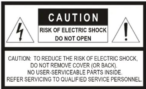
Explanation of Symbols
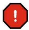
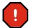
WARNING! The exclamation point in a red octagon is a WARNING. Failure to take or avoid a specific action could result in physical harm to a person or irreparable damage to equipment.

Caution The lightning flash with arrowhead symbol within an equilateral triangle alerts the user to the presence of uninsulated dangerous voltage within the enclosure of the product that may be of sufficient magnitude to constitute a risk of electric shock to the person.
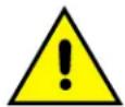
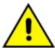
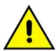
Caution The exclamation point in a yellow equilateral triangle is a Caution. Failure to take or avoid a specified action could result in loss of data or damage to equipment and may contain important operating and maintenance servicing information.
FCC Compliance Statement
Information to the User: This equipment has been tested and found to comply with the limits for a Class B digital device. Pursuant to Part 15 of the FCC Rules, these limits are designed to provide reasonable protection against harmful interference in a residential installation. This equipment generates, uses, and can radiate radio frequency energy and, if not installed and used in accordance with the instruction manual, may cause harmful interference to radio communications. However, there is no guarantee that interference will not occur in a particular installation.
If this equipment does cause harmful interference to radio or television reception, which can be determined by turning the equipment off and on, the user is encouraged to try to correct the interference. For example, try orienting or relocating the receiving antenna, increasing the separation between the equipment and receiver, or connecting the equipment to an outlet on a different circuit.
- Changes or modifications not expressly approved by the party responsible for compliance could void the user's authority to operate the equipment.
- Users of the product are responsible for checking and complying with all federal, state and local laws and statutes concerning the monitoring and recording of video and audio signals. Honeywell Video Systems shall not be held responsible for the use of this product in violation of current laws and statutes.
Canadian Compliance Statement
Manufacturer's Declaration of Conformance
North America
The equipment supplied with this guide conforms to UL60065, CAN/CSA C22.2 No. 60065-03.
Europe
The manufacturer declares that the equipment supplied with this guide is compliant with the essential protection requirements of the EMC directive 2004/108/EC and the Low Voltage Directive LVD 2006/95/EC, conforming to the requirements of standards EN 55022 for emissions, EN 50130-4 for immunity, and EN 60065 for Electrical Equipment safety.
Warnings and Cautions
- All installations and servicing must be performed by qualified technical personnel and must be in accordance with all national and local mechanical and electrical codes.
- To prevent injury, this apparatus must be securely attached to the wall/ceiling in accordance with the installation instructions.
- Ensure the mounting surface and installation hardware can hold the combined weight of the gimbal, housing, lower dome and mount.
- To prevent damage to the camera, follow standard industry precautions for electrostatic discharge-sensitive devices.
- Consider using a UPS source to ensure satisfactory performance.
- Using replacement parts or accessories other than the original manufacturers may invalidate the warranty.
- To make good wire contact and ensure the wire does not short to adjacent wires, fully insert the wire in the hole on the terminal strip.
- Ensure there are no bare wires touching or faulty operation may occur.
Important Safety Instructions
BEFORE OPERATING OR INSTALLING THE UNIT, READ AND FOLLOW ALL INSTRUCTIONS. AFTER INSTALLATION, retain the safety and operating instructions for future reference.
- HEED WARNINGS - Adhere to all warnings on the unit and in the operating instructions.
-
INSTALLATION
-
Do not install in any extremely humid, dusty, hot/cold environments (where the operating temperature is outside the recommended range of 14^ to 122^ [-10^ to +50^] ).
- Any wall or ceiling mounting of the product should follow the instructions for the mount used and use best installation practice appropriate for the structure and material the mount is being attached to.
-
Avoid installing operating or storing the unit close to sources of powerful electromagnetic radiation, such as radio or TV transmitters or close to fluorescent lamps or objects reflecting light, or under unstable light sources, which may cause flickering.
-
POWER SOURCES - This product should be operated only from the type of power source indicated on the marking label. If you are not sure of the type of power supplied to your facility, consult your product dealer or local power company.
- HEAT - Situate away from items that produce heat or are heat sources such as radiators, heat registers, stoves, or other products (including amplifiers).
- WATER AND MOISTURE - This product is designed for indoor use only. Do not use this unit near water or in an unprotected outdoor installation, or any area classified as a wet location.
-
MOUNTING SYSTEM - Use only with a mounting system recommended by the manufacturer, or sold with the product.
-
ATTACHMENTS - Do not use attachments not recommended as they may result in the risk of fire, electric shock, or injury to persons.
- ACCESSORIES - Only use accessories specified by the manufacturer.
- CLEANING - Do not use liquid cleaners or aerosol cleaners. Use a damp cloth for cleaning.
- SERVICING - Do not attempt to service this unit yourself as opening or removing covers may expose you to dangerous voltage or other hazards. Refer all servicing to qualified service personnel.
- REPLACEMENT PARTS - When replacement parts are required, be sure the service technician has used replacement parts specified by the manufacturer or have the same characteristics as the original part. Unauthorized substitutions may result in fire, electric shock or other hazards.
Warranty and Service

The Use of CSA Certified/UL Listed Class 2 power adapters is required to ensure compliance with electrical safety standards.
Subject to the terms and conditions listed on the Product Warranty Card, during the warranty period Honeywell will repair or replace, at its sole option, free of charge, any defective products returned prepaid.
In the event you have a problem with any Honeywell Systems Group product, please call Customer Service for assistance or to request a Return Merchandise Authorization (RMA) number. Be sure to have the model number, serial number, and the nature of the problem available for the technical service representative. Prior authorization must be obtained for all returns, exchanges, or credits. Items shipped to Honeywell without a clearly identified Return Merchandise Authorization (RMA) number may be refused.
See the back cover for contact details.
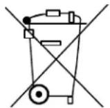
WEEE (Waste Electrical and Electronic Equipment). Correct disposal of this product (applicable in the European Union and other European countries with separate collection systems). This product should be disposed of, at the end of its useful life, as per applicable local laws, regulations, and procedures.
Contents
ACUIX ES Fixed Camera Overview. 9
Housing and Mount Options 9
Surface Mount or Indoor Pendant Housing and Gimbal Layout. 10
In-Ceiling Housing and Gimbal Layout. 12
Cable Requirements and Guidelines. 13
Installing the ACUIX ES Fixed Camera. 14
Step 1: Install the Housing ..... 14
Step 2: Connect Video and Power and Adjust Camera Position .....17
Step 3: Set the DIP Switches for Optional Camera Settings ..... 18
Step 4: Install the PCB Board Cover ..... 19
Step 5: Install the Trim Ring or Cover and the Lower Dome ..... 20
Camera Specifications . . . . . . . . . . . . . . . . . . . . . . . . . . . . . . . . . . . . . . . . . . . . . . . . . . . . . . . . . . 21
Pendant Mount Specifications 22
Installing the ACUIX ^TM ES Fixed Camera
Note
Refer to the on-line product library to access up-to-date electronic documents in PDF format including data sheets, quick references, installation and user guides, specifications, and product notices.
http://www.honeywellvideo.com/support/literature/index.html
ACUIX ES Fixed Camera Overview
Housing and Mount Options
Note PAL and NTSC video formats are based on camera model.
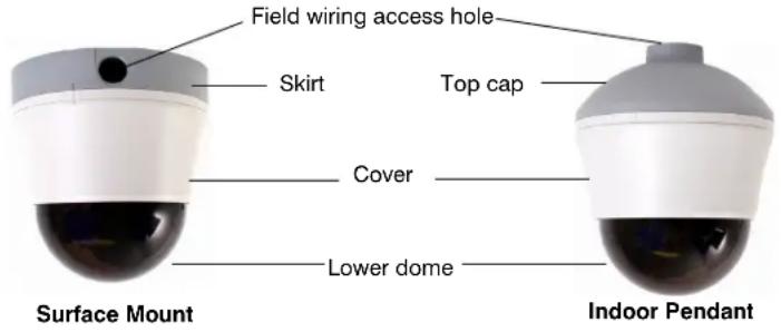
Figure 1 ACUIX ES Fixed Camera Housing and Mount Options

Table 1 ACUIX ES Fixed Dome Models
| Housing Camera and Communication Lower dome* NTSC Model PAL Model | |||
| Surface mount/indoor pendant | 2.8 - 10mm VFAI camera, video over coax | smoked lower dome HDV1NSFS HDV1PSFS | |
| 2.8 - 10mm VFAI camera, video over coax | clear lower dome HDV1NSFC HDV1PSFC | ||
| In-ceiling 2.8 - 10mm VFAI camera, video over coax | smoked lower dome with white trim ring | HDV1NDFSW HDV1PDFSW | |
| clear lower dome with white trim ring | HDV1NDFCW HDV1PDFCW | ||
| * Only the in-ceiling model has a trim ring | |||
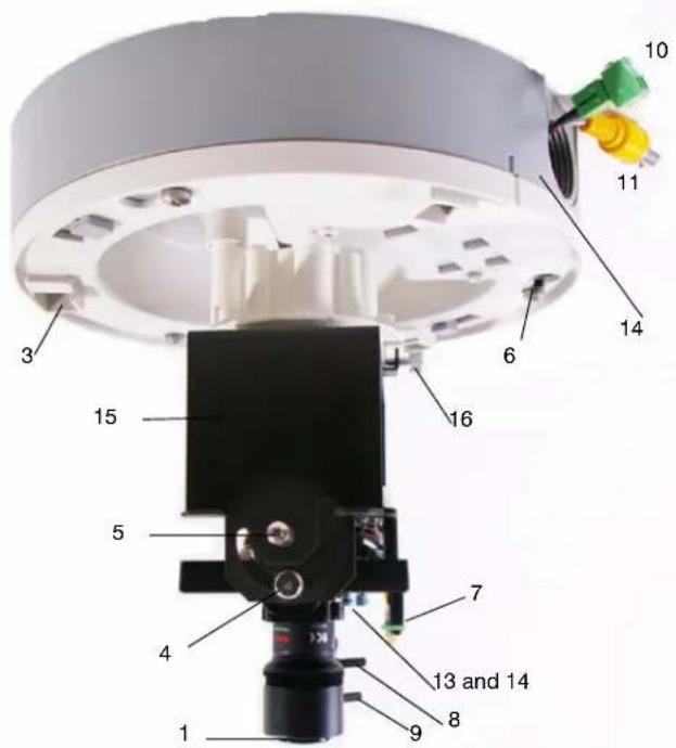
Surface Mount or Indoor Pendant Housing and Gimbal Layout
Figure 2 Surface or Pendant Mount Layout (Top View)
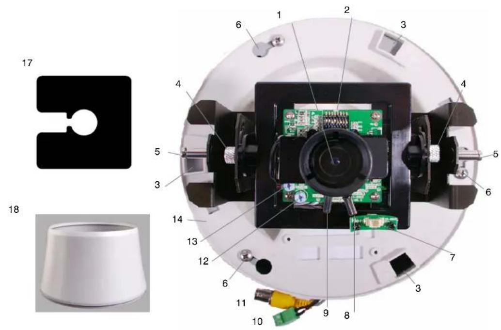
Table 2 Legend for Surface/Pendant Mount Figures 2 and 3
| 1 Camera lens 10 24 VAC / 12 VDC power input connector | |
| 2 Mode setting DIP switches 11 Video output connector | |
| 3 Holes to insert cover 12 Level adjustment pot (Iris level) | |
| 4 Tilt screw (x2) 13 VPH (V Phase) adjustment pot (24 VAC only) | |
| 5 Lower dome screw (x2) 14 Surface mount skirt | |
| 6 Pan screws (x3) for surface or pendant 15 Fixed camera bracket/gimbal | |
| 7 Monitor out (second video) 16 Bracket/gimbal pivot and locking screw | |
| 8 Focus lever to set focus | 17 PCB cover. Also see Figure 10. |
| 9 Zoom lever to set focal length (lever closest to camera lens) | 18 Cover |
Figure 3 Surface Mount Installed on Ceiling
In-Ceiling Housing and Gimbal Layout
Figure 4 In-ceiling Housing Layout
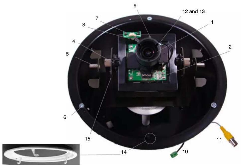
Table 3 Legend for In-ceiling Housing Figure4
| 1 Camera lens 9 Zoom lever to set focal length (lever closest to camera lens) | |
| 2 Mode setting DIP switches 10 24 VAC / 12 VDC power input connector | |
| 3 not applicable 11 Video output connector | |
| 4 Tilt screw (x2) 12 Level adjustment pot (Iris level) | |
| 5 Lower dome screw (x2) 13 VPH (V Phase) adjustment pot (24 VAC only) | |
| 6 Turning screws attached to wing tabs (x3) 14 Tabs to hook trim ring under (x3) and trim ring | |
| 7 Monitor out (second video) 15 Fixed camera bracket/gimbal | |
| 8 Focus lever to set focus 16 Bracket/gimbal pivot and locking screw(not shown see Figure 3) | |
| 17 PCB cover. Not shown. See Figure 10. |
Cable Requirements and Guidelines
Calculations are based on an unregulated linear power supply. Using a regulated or switching power supply can increase the cable distance. Honeywell recommends using a CSA Certified/UL listed Class 2 power adapter to ensure compliance with electrical safety standards.
Table 4 Maximum Power Supply Cable Length for 24 VAC or 12 VDC
| Power Supply | Wire Gauge (AWG) | mm^2 | Feet Meters |
| 24 VAC | 24 0.21 991 302 | ||
| 22 0.33 1601 488 | |||
| 18 0.82 4061 1238 | |||
| 16 1.30 6462 1970 | |||
| 12 VDC | 24 0.21 50 15 | ||
| 22 0.33 100 30 | |||
| 18 0.82 200 60 | |||
| 16 1.30 360 108 | |||
Table 5 Maximum Video Coaxial Cable Length
| Cable Type RG-59 RG-6 RG-11 | |||
| Wire gauge 23 AWG* 18 AWG* 14 AWG* | |||
| Maximum length | 750 feet | 1500 feet | 2000 feet |
| 229 meters | 457 meters | 610 meters | |
| *Copper clad steel core, 95% braided shield | |||
Installing the ACUIX ES Fixed Camera
Step 1: Install the Housing
Installing the Surface Mount or Indoor Pendant Housing
Note All ACUIX ES pendant/surface mount shipments include both the skirt and top cap. Use the part appropriate to the installation; the other is a spare part.
Figure 5 Surface Mount and Indoor Pendant Layout
Surface Mount
- Select a location to install the surface mount and housing.
- Pull all the field wiring and power and video connectors through the skirt wiring access holes.
- Mount the skirt on the ceiling using the appropriate hardware.
- Finish pulling field wiring through the skirt and cut the cable length to 6 inches (152 mm).
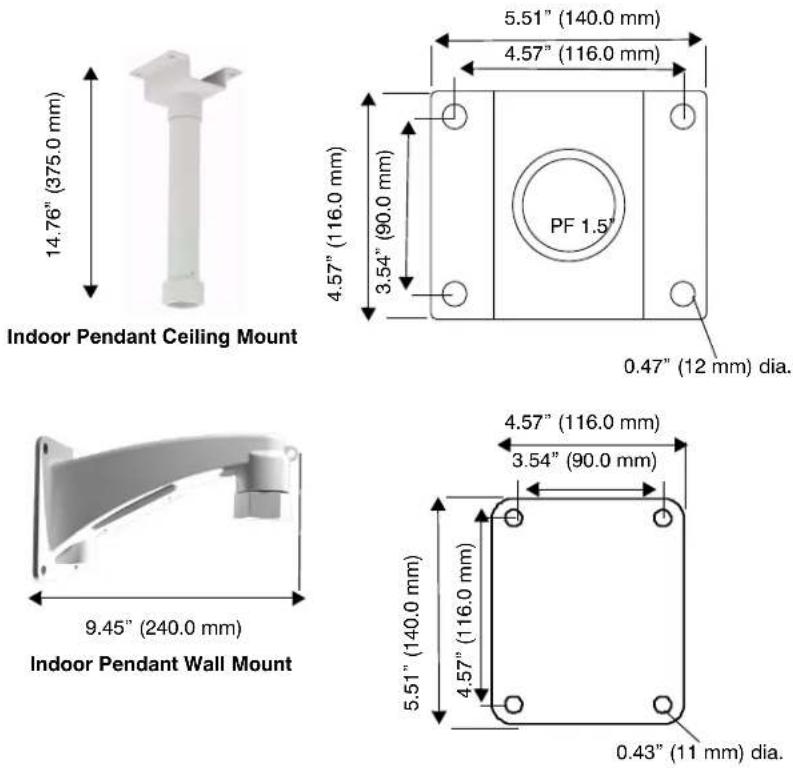
Indoor Pendant with a Ceiling or Wall Mount
- Select a location to install the components and applicable mount.
- Drill the mount hole size into the ceiling or wall. For ceiling and wall mount hole dimensions see Table 8 and Figure 6.
- Before securing the mount to the wall or ceiling, pull the field wiring through the mount, ensuring that it extends at least 12 inches (305 mm) past the end of the pipe.
- Screw the housing top cap into the wall or ceiling pipe.
- Finish pulling the field wiring from the mount through the top cap and cut the cable length to 6 inches (152 mm).
Figure 6 Indoor Pendant Ceiling and Wall Mount Dimensions
Installing the In-Ceiling Housing
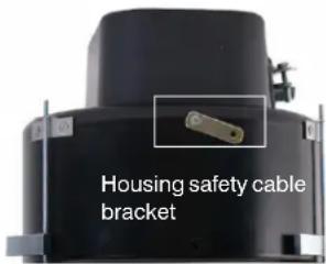
You can install the in-ceiling housing in a dropped (false) ceiling or a hard ceiling. For dropped ceiling installations, use a separately ordered ceiling plate (Honeywell part number 517082-7130). In addition to the other items normally supplied by the installer, the following may also be required:
- Tape or plastic channel to prevent dust and material from falling from the ceiling.
- Safety cable - a 3/32" (approximately 2.4 mm) plastic coated aircraft cable with a looping sleeve is recommended.
Figure 7 In-ceiling Dome Layout and Wing Tab Spacing
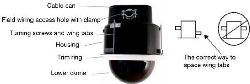
Note The mounting template for hard ceiling installations is included separately.
- Select a location to install the housing and prepare the ceiling and/or ceiling tile:
Hard Ceiling
- Using the mounting template, cut a 7 5/8" (194 mm) diameter hole in the ceiling. If the ceiling is drywall or plaster, it is recommended to seal the entire perimeter of the hole with tape or plastic channel to prevent dust and material from contaminating the camera.
Dropped (False) Ceiling
a. Remove the ceiling panel at the installation location.
b. Place the ceiling tile on the dropped ceiling plate (Honeywell part number 517082-7130).
c. Trim the ceiling tile and press it into the dropped ceiling plate.
d. Using the supplied mounting template, cut a 7 5/8" (194 mm) diameter hole in the ceiling tile flush with the hole in the center of the plate.
- If required, secure a safety cable to a building support structure. Attach the safety cable (from the building support structure) to the outside of the housing by:
a. Threading the safety cable through a looping sleeve,
b. Attach to the safety cable bracket on the housing,
c. Back through the looping sleeve, and then
d. Crimp the looping sleeve to secure the safety cable.
- Unsnap/remove the cable can and pull all the wiring through the cable can wiring hole. Ensure the wiring extends at least 12 inches (305 mm) past the end of the hole and cut the cable length to 6 inches (152 mm). See Figures 4 and 7.
- Tighten the wire clamp to hold the wires in place.
- Snap the cable can back into place by inserting the two tabs on the cable can into the two holes on the housing to secure it.
- Insert the cable can and housing through the hole in the ceiling.
a. Turn the wing tab turning screws to make sure the space between the wing tabs on the housing and the housing flange is greater than the thickness of the ceiling.
- To increase the space, turn the screw clockwise.
- To decrease the space, turn the screw counterclockwise.
b. Make sure the wing tabs on the housing are staggered so the tabs are not at the same height. See Figure 7.
c. Position the wing tabs flat against the housing.
d. Using a Phillips screwdriver, turn the three screws in the housing clockwise to rotate the tabs out and tighten the tabs against the ceiling.
- The recommended maximum torque is 1–1.25 N·m (Newton meters) or 0.74–0.92 lbf·ft (pound-force-foot) or 8.85–11.06 lbf·in (pound-force-inch).
Step 2: Connect Video and Power and Adjust Camera Position
Be careful while adjusting the camera position and rotating the gimbal. Do not over rotate the gimbal or bracket or it will damage the cables.
-
See Figure 2 (surface and pendant) and Figure 4 (in-ceiling) and for the location of the 24 VAC/12 VDC power connector, video output connector and monitor out (second video) plug.
-
Make the connections to the power and video. If required, connect to the monitor out plug during the installation process and while setting the parameters in Step 3: Set the DIP Switches for Optional Camera Settings.
-
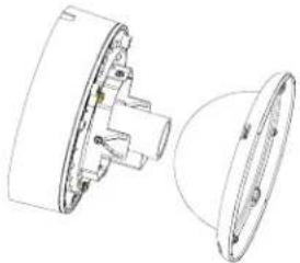
While monitoring the video signal, adjust the camera position as required for the site. See Figure 8 for each option below. Note that the surface mount housing is shown.
a. Loosen the gimbal pivot and locking screw to rotate the camera bracket/gimbal left or right.
b. Loosen the tilt screws to angle the camera gimbal/bracket up or down.
c. If required for focusing, place the lower dome in front of the lens as shown to the right. Turn the focus lever left or right to set focus using the bottom locking screw (closest to the camera board). Turn the zoom lever left or right to set focal length.
- Tighten both the tilt screws and the gimbal pivot and locking screw to lock the gimbal assembly and the camera position in place.
natural_image
Technical line drawing of a mechanical component with cross-sectional view (no text or symbols)Figure 8 Adjust the Camera and Gimbal Position
natural_image
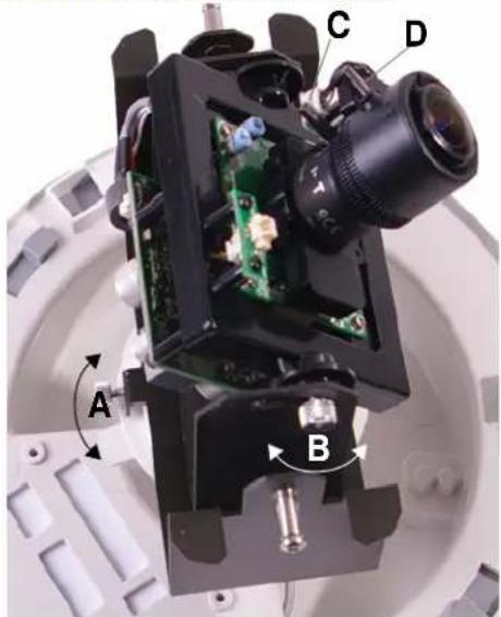
Close-up of a mechanical optical device with labeled components (A, B, C, D) and internal circuit board (no readable text or symbols beyond labels)Step 3: Set the DIP Switches for Optional Camera Settings
If the defaults need changing see Figure 9 and Table 6 to set DC/AES, white balance, BLC (backlight compensation), AGC (automatic gain control), flickerless, and line lock (24 VAC only).
Figure 9 ACUIX ES Fixed DIP Switch Default Settings
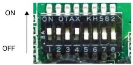
Table 6 ACUIX ES Fixed Camera DIP Switch Options
| Switch Default Description | ||
| 1 ON (DC) DC/AES selection: Leave ON | ||
| 2 ON (AWB) White balance - Set ON for AWB or OFF for ATW | ||
| 3 | OFF (BLC OFF) | BLC (backlight compensation). Set to ON to have the camera adjust the exposure to compensate for situations where the subject is lit from behind. |
| 4 | ON (AGC ON) | AGC (automatic gain control): Set to ON to have the camera adjust the picture for low light conditions. |
| 5 OFF Not used | ||
| 6 | OFF (FLK OFF) | Flickerless: Set the FL switch to ON to remove the flicker in a picture.The shutter speed is 1/100 second for PAL and 1/120 second for NTSC. |
| 7 | OFF (LL OFF) | LL (line lock): Set the camera synchronization to ON (internal) or OFF (line lock, only available with 24 VAC). |
| 8 OFF | Not used | |
Adjusting the Brightness Level
- While monitoring the video signal, use a screwdriver to rotate the LEVEL adjustment pot to compensate for the iris level. L (low) makes the picture darker and H (high) makes the picture brighter.
Adjusting the V Phase and Line Lock Function
- Set DIP switch position 7 ON to activate line lock (24 VAC only). See Figure 9.
- While monitoring the video signal, use a screwdriver to rotate the V PH (V phase) adjustment pot to adjust the phase difference between cameras.
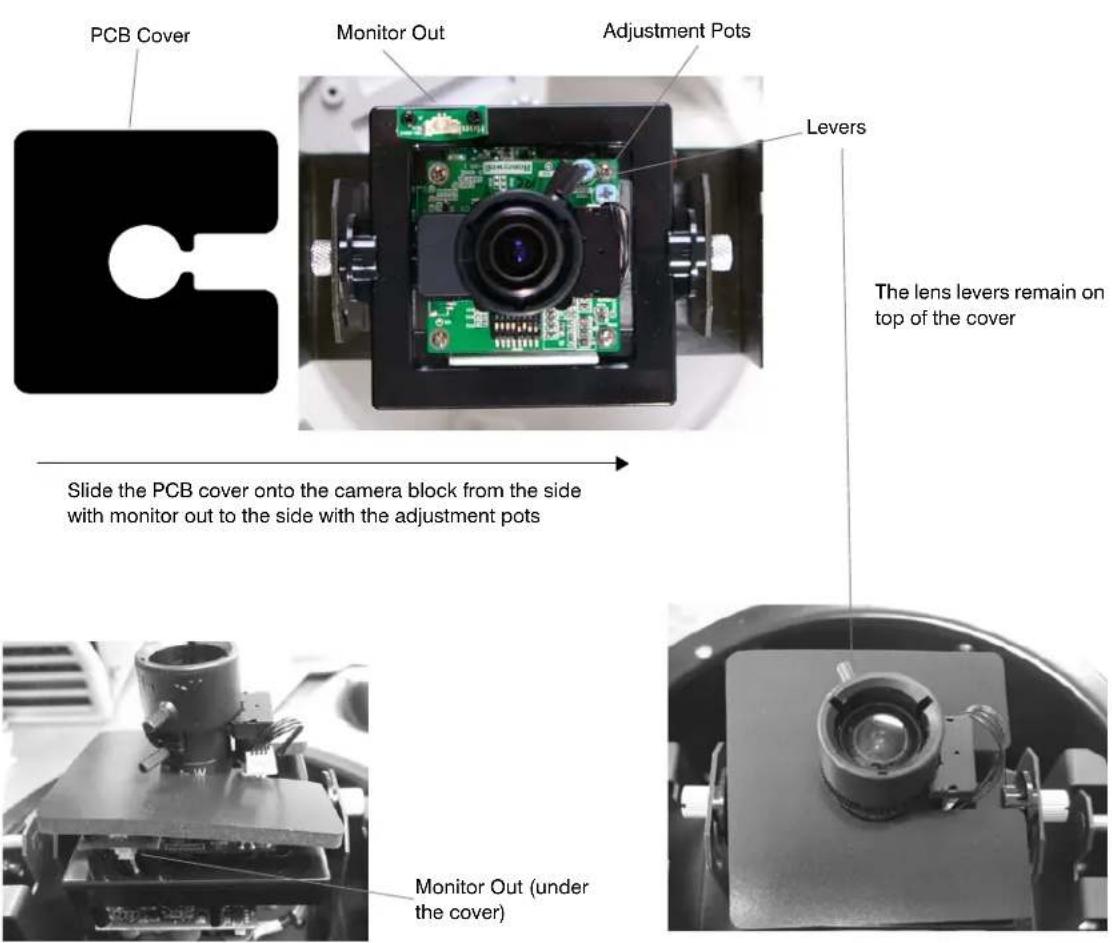
Step 4: Install the PCB Board Cover
Note The purpose of the PCB board cover is to prevent anyone from seeing the inside of the camera from the ground. It is used for all installations.
- Align the open side of the PCB cover with the camera block (which includes the lens and green PCB board) using Figure 10 as a guide.
- Start at the monitor out side of the camera block and slide the PCB cover towards the two adjustment pots.
- Adjust the PCB cover to be under the lens levers and on top of the monitor out.
Figure 10 PCB Board Cover Installation
Step 5: Install the Trim Ring or Cover and the Lower Dome
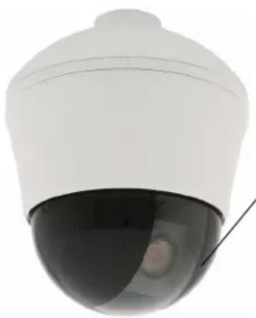
Smoked lower domes only: In order to ensure maximum illumination, the light colored area through the center of the lower dome must be oriented correctly over the lens as in Figure 11.
Installing the Lower Dome on Surface Mount or Indoor Pendant
- For both pendant and surface mount installations, align the three hooks on the housing cover with the three holes on the inside of the top cap or skirt. Rotate the housing cover until it is secure inside the top cap or skirt. See Figure 2.
- Smoked domes only: Rotate the lower dome so that the clear slot that runs down the center faces the front of the camera and is aligned with the camera lens. See Figure 11.
- Align the two holes on the lower dome with the two screw holes on either side of the gimbal. Use the two screws provided to secure the lower dome to the gimbal.
Figure 11 Smoked Lower Dome Orientation Over the Lens
natural_image
Close-up of a white security camera with a black dome and cable (no text or symbols visible)Align the clear center strip in front of the lens to maximize illumination when installing a smoked lower dome
Installing the Lower Dome on an In-Ceiling
- Insert the trim ring into the inside of the housing and rotate it until the three hooks on the trim ring are aligned and secure underneath the three round tabs. See Figure 4.
- Smoked domes only: Rotate the lower dome so that the clear slot that runs down the center faces the front of the camera and is aligned with the camera lens. See Figure 11.
- Align the two holes on the lower dome with the two holes on either side of the gimbal.
- Use the screws provided to secure the lower dome to the gimbal.
Camera Specifications
Table 7 ACUIX ES Fixed Camera Specifications
| Item Specification | |
| Video Signal Specifications | |
| Video Standard Based on camera model | NTSC or PAL High Resolution |
| Scanning System 525 lines, 2:1 Interlace | |
| Image Sensor 1/3" Interline Transfer CCD | |
| Number of Pixels (H x V) 768 x 494 (NTSC) 752 x 582 (PAL) | |
| Minimum Illumination Clear dome: 0.6 lux @ F1.3 (AGC on, 50 IRE) Smoked dome: 2 lux @ F1.3 (AGC on, 50 IRE) | |
| Horizontal Resolution 540 TVL | |
| Video Output 1.0 Vp-p @ 75 Ohms | |
| Sync System 12 VDC: Internal, 24 VAC: Line lock | |
| S/N Ratio 50 dB (AGC Off) | |
| Auto Electronic Shutter 1/60 - 1/100,000 sec (NTSC) 1/50 - 1/100,000 sec (PAL) | |
| Lens Iris Control Direct drive (DC) AI | |
| Lens Type 2.8 mm to 10.0 mm Vari-focal auto iris, F1.3 | |
| Focal Length f = 2.8 mm to 10 mm | |
| Gamma 0.45 | |
| Video Signal Specifications - DIP Switch Available Settings | |
| AGC (automatic gain control) | ON (default)/OFF |
| BLC (backlight compensation) | ON/OFF (default) |
| AES Selection | ON for DC or OFF for AES |
| Flickerless | ON/OFF (default) |
| Line Lock (only available with 24 VAC) | ON / OFF (default) |
| White balance | ON (default) for AWB or OFF for ATW |
| Electrical Specifications | |
| Input Voltage 12 VDC/24 VAC | |
| Input Tolerance | 11 - 16 VDC, 17 - 28 VAC |
| Power Consumption | 3.5 W (max) |
Table 7 ACUIX ES Fixed Camera Specifications
| Item Specification |
| Mechanical |
| Dimensions (WxH) • In-ceiling housing: 6.0" H x 8.13" dia. (152 mm H x 206.4 mm dia.)Surface mount housing: 5.0" H x 7.6" dia. tapering to 6.0" dia. (128 mm H x 194 mm dia. tapering to 152 mm dia.)Pendant housing: 6.6" H x 7.6" dia. tapering to 6.0" dia. (167.64 mm H x 194 mm dia. tapering to 152 mm dia.) Lower dome: 5.7" (146 mm) dia.Lower dome: 5.7" (146 mm.) dia. |
| Weight • 1.9 lb (0.84 kg) |
| Construction • Surface mount/outdoor pendant housing: PolycarbonateIn-ceiling housing: metalLower dome all models: Polycarbonate |
| Environmental |
| Temperature • Operating: -14°F to 122°F (-10°C to 50°C)Storage: -4°F to 140°F (-20°C to 60°C) |
| Relative Humidity 0% to 90%, non-condensing |
| Regulatory |
| Emissions FCC, CE (EN55022) |
| Immunity CE (EN50130-4) |
| Safety UL60065, EU: 73/23/EEC LVD |
Pendant Mount Specifications
Table 8 ACUIX ES Pendant Ceiling and Wall Mount Specifications
| Specification Ceiling Mount Wall Mount | ||
| Dimensions 14.76" (375 mm) (H) x 5.51" (140 mm) (W) x 4.57" (116 mm) (L) | 5.51" (140 mm) (H) x 4.57" (116 mm) (W) x 9.45" (240 mm) (L) | |
| Pipe specification 1.5" NPT | 1.5" PT TAP | |
| Weight | 4 lbs (1.8 kg) | 8.6 lbs (3.9 kg) |
| Maximum Load | Up to 25 lbs (11.7 kg) | Up to 22 lbs (10 kg) |
| Material | Aluminum | Aluminum |
ACUIX™ ES Fixed Camera Installation Guide
Honeywell Systems Group (Head Office)
2700 Blankenbaker Pkwy, Suite 150
Louisville, KY 40299, USA
www.honeywellvideo.com
+1.800.796.2288
Honeywell Systems Group Europe/South Africa
Aston Fields Road, Whitehouse Industrial Estate
Runcorn, Cheshire, WA7 3DL, UK
www.honeywell.com/security/uk
+44.01928.754028
Honeywell Systems Group Pacific
Unit 5, Riverside Center, 24-28 River Road West
Parramatta, NSW 2150, Australia
www.honeywellsecurity.com.au
+61.2.8837.9300
Honeywell Systems Group Asia
35F Tower A, City Center, 100 Zun Yi Road
Shanghai 200051, China
www.asia.security.honeywell.com
+86 21.5257.4568
Honeywell Systems Group Middle East/N. Africa
Post Office Box 18530
LOB Building 08, Office 199
Jebel Ali, Dubai, United Arab Emirates
www.honeywell.com/security/me
+971.04.881.5506
Honeywell Systems Group Northern Europe
Ampèrestraat 41
1446 TR Purmerend, The Netherlands
www.honeywell.com/security/nl
+31.299.410.200
D-72458 Albstadt, Germany
www.honeywell.com/security/de
+49.74 31.8 01.0
Honeywell Systems Group France
Immeuble Lavoisier
92160 Antony, France
www.honeywell.com/security/fr
+33.(0).1.40.96.20.50
Honeywell Systems Group Italia SpA
www.honeywell.com/security/it
+39.02.4888.051
Honeywell Systems Group España
www.honeywellvideo.com
+1.800.796.CCTV (North America only)
HVSsupport@honeywell.com
Document 800-02848 - Rev C - 03/2009
© 2009 Honeywell International Inc. All rights reserved. No part of this publication may be reproduced by any means without written permission from Honeywell. The information in this publication is believed to be accurate in all respects. However, Honeywell cannot assume responsibility for any consequences resulting from the use thereof. The information contained herein is subject to change without notice. Revisions or new editions to this publication may be issued to incorporate such changes.
- Explanation of Symbols
- FCC Compliance Statement
- Canadian Compliance Statement
- Manufacturer's Declaration of Conformance
- North America
- Europe
- Warnings and Cautions
- Important Safety Instructions
- BEFORE OPERATING OR INSTALLING THE UNIT, READ AND FOLLOW ALL INSTRUCTIONS. AFTER INSTALLATION, retain the safety and operating instructions for future reference.
- Warranty and Service
- Contents
- Installing the ACUIX TM ES Fixed Camera
- Note
- ACUIX ES Fixed Camera Overview
- Housing and Mount Options
- Surface Mount or Indoor Pendant Housing and Gimbal Layout
- In-Ceiling Housing and Gimbal Layout
- Cable Requirements and Guidelines
- Installing the ACUIX ES Fixed Camera
- Step 1: Install the Housing
- Installing the Surface Mount or Indoor Pendant Housing
- Surface Mount
- Indoor Pendant with a Ceiling or Wall Mount
- Installing the In-Ceiling Housing
- Hard Ceiling
- Dropped (False) Ceiling
- Step 2: Connect Video and Power and Adjust Camera Position
- Step 3: Set the DIP Switches for Optional Camera Settings
- Adjusting the Brightness Level
- Adjusting the V Phase and Line Lock Function
- Step 4: Install the PCB Board Cover
- Step 5: Install the Trim Ring or Cover and the Lower Dome
- Installing the Lower Dome on Surface Mount or Indoor Pendant
- Installing the Lower Dome on an In-Ceiling
- Camera Specifications
- Pendant Mount Specifications
- Honeywell Systems Group (Head Office)
- Honeywell Systems Group Europe/South Africa
- Honeywell Systems Group Pacific
- Honeywell Systems Group Asia
- Honeywell Systems Group Middle East/N. Africa
- Honeywell Systems Group Northern Europe
- Honeywell Systems Group France
- Honeywell Systems Group Italia SpA
- Honeywell Systems Group España
Brand : HONEYWELL
Model : Acuix HDV1NSFC
Category : Security Camera