
Acuix HDVFNWBC - Security Camera HONEYWELL - Free user manual and instructions
Find the device manual for free Acuix HDVFNWBC HONEYWELL in PDF.

| Product Type | PTZ High Speed Analog Dome Security Camera |
| Image Sensor | 1/4-inch CCD (specific model dependent) |
| Effective Pixels | NTSC: 768 x 494; PAL: 752 x 582 |
| Minimum Illumination | 0.001 lux (color) / 0.0001 lux (B&W) typical |
| Lens | Optical zoom up to 35x (model dependent) |
| Digital Zoom | Up to 12x (programmable limit) |
| Pan Range | 360° continuous |
| Tilt Range | 0° to -90° (with -5° tilt limit option) |
| Pan Speed | 0.1° to 480° per second |
| Tilt Speed | 0.1° to 200° per second |
| Presets | Up to 150 (protocol dependent) |
| Preset Tours | Up to 16 tours, each with up to 64 presets |
| Privacy Zones | Up to 32 programmable zones with mask color selection |
| Video Output | 1 Vp-p composite, 75 ohms (coax or UTP) |
| Control Protocols | Honeywell MAXPRO, Diamond, IntelliBus, VCL, Pelco P/D |
| Communication | RS485 (twisted pair) or coax control (VCL UTC) |
| Power Requirements | 24 VAC ±10%, 1.9 A (indoor) / 2.5 A (outdoor) |
| Operating Temperature | Indoor: 0°C to 40°C; Outdoor: -40°C to 60°C (with heater) |
| Dimensions (Dome) | Approx. 7.6 in (193 mm) diameter, variable height |
| Weight (Dome complete) | Approx. 5.5 lb (2.5 kg) depending on housing |
| Mounting Options | In-ceiling, pendant, wall, corner, pole, parapet |
| Cleaning | Use damp cloth; avoid liquid cleaners; clean lens with alcohol |
| Certifications | FCC Class B, CE, UL, CSA |
| Warranty | Standard Honeywell warranty (see product card) |
Frequently Asked Questions - Acuix HDVFNWBC HONEYWELL
User questions about Acuix HDVFNWBC HONEYWELL
0 question about this device. Answer the ones you know or ask your own.
Ask a new question about this device
Download the instructions for your Security Camera in PDF format for free! Find your manual Acuix HDVFNWBC - HONEYWELL and take your electronic device back in hand. On this page are published all the documents necessary for the use of your device. Acuix HDVFNWBC by HONEYWELL.
USER MANUAL Acuix HDVFNWBC HONEYWELL
PTZ High Speed Analog Dome
Installation and Configuration Guide
Revisions
Rev Date Revisions
A 12/08 New document to replace 800-01023
Explanation of Symbols

WARNING! The exclamation point in a red octagon is a WARNING. Failure to take or avoid a specific action could result in physical harm to a person or irreparable damage to equipment.

Caution The lightning flash with arrowhead symbol within an equilateral triangle alerts the user to the presence of uninsulated dangerous voltage within the enclosure of the product that may be of sufficient magnitude to constitute a risk of electric shock to the person

Caution The exclamation point in a yellow equilateral triangle is a Caution. Failure to take or avoid a specified action could result in loss of data or damage to equipment and may contain important operating and maintenance servicing information.
FCC Compliance Statement
Information to the User: This equipment has been tested and found to comply with the limits for a Class B digital device. Pursuant to Part 15 of the FCC Rules, these limits are designed to provide reasonable protection against harmful interference in a residential installation. This equipment generates, uses, and can radiate radio frequency energy and, if not installed and used in accordance with the instruction manual, may cause harmful interference to radio communications. However, there is no guarantee that interference will not occur in a particular installation.
If this equipment does cause harmful interference to radio or television reception, which can be determined by turning the equipment off and on, the user is encouraged to try to correct the interference. For example, try orienting or relocating the receiving antenna, increasing the separation between the equipment and receiver, or connecting the equipment to an outlet on a different circuit.

Changes or modifications not expressly approved by the party responsible for compliance could void the user's authority to operate the equipment.
Users of the product are responsible for checking and complying with all federal, state and local laws and statutes concerning the monitoring and recording of video and audio signals. Honeywell Systems Group shall not be held responsible for the use of this product in violation of current laws and statutes.
Canadian Compliance Statement
This Class B digital apparatus complies with Canadian ICES-003.
Manufacturer's Declaration of Conformance
North America
The equipment supplied with this guide conforms to UL60065, CAN/CSA C22.2 No. 60065:03.
Europe
The manufacturer declares that the equipment supplied with this guide is compliant with the essential protection requirements of the EMC directive 2004/108/EC and the Low Voltage Directive LVD 2006/95/EC, conforming to the requirements of standards EN 55022 for emissions, EN 50130-4 for immunity, and EN 60065 for Electrical Equipment safety.
Warnings and Cautions
Read the following cautions and warnings prior to installation and use of this product.

Installation and servicing must be performed by qualified personnel in accordance with local codes and regulations.
To prevent injury, this apparatus must be securely attached to the wall/ceiling in accordance with the installation instructions.

Consider using a UPS source to ensure satisfactory performance.
Using replacement parts or accessories other than the original manufacturers may invalidate the warranty.

Important Safety Instructions
BEFORE OPERATING OR INSTALLING THE UNIT, READ AND FOLLOW ALL INSTRUCTIONS. AFTER INSTALLATION, retain the safety and operating instructions for future reference
- HEED WARNINGS - Adhere to all warnings on the unit and in the operating instructions.
-
INSTALLATION
-
Install in accordance with the manufacturer's instructions.
• Installation and servicing should be performed only by qualified and experienced technicians to conform to all local codes and to maintain your warranty. - Do not install the unit in an extremely hot or humid location, or in a place subject to dust or mechanical vibration. The unit is not designed to be waterproof. Exposure to rain or water may damage the unit.
-
Any wall or ceiling mounting of the product should follow the manufacturer's instructions and use a mounting kit approved or recommended by the manufacturer.
-
POWER SOURCES - This product should be operated only from the type of power source indicated on the marking label. If you are not sure of the type of power supplied to your facility, consult your product dealer or local power company.
- HEAT - Situate away from items that produce heat or are heat sources such as radiators, heat registers, stoves, or other products (including amplifiers).
- WATER AND MOISTURE - Do not use this unit near water or in an unprotected outdoor installation, or any area classified as a wet location.
- MOUNTING SYSTEM - Use only with a mounting system recommended by the manufacturer, or sold with the product.
- ATTACHMENTS - Do not use attachments not recommended by the product manufacturer as they may result in the risk of fire, electric shock, or injury to persons.
- ACCESSORIES - Only use accessories specified by the manufacturer.
-
CLEANING - Do not use liquid cleaners or aerosol cleaners. Use a damp cloth for cleaning.
-
SERVICING - Do not attempt to service this unit yourself as opening or removing covers may expose you to dangerous voltage or other hazards. Refer all servicing to qualified service personnel.
- REPLACEMENT PARTS - When replacement parts are required, be sure the service technician has used replacement parts specified by the manufacturer or have the same characteristics as the original part. Unauthorized substitutions may result in fire, electric shock or other hazards.
Warranty and Service
Subject to the terms and conditions listed on the Product Warranty Card, during the warranty period Honeywell will repair or replace, at its sole option, free of charge, any defective products returned prepaid.
In the event you have a problem with any Honeywell product, please call Customer Service for assistance or to request a Return Merchandise Authorization (RMA) number. Be sure to have the model number, serial number, and the nature of the problem available for the technical service representative.
In the U.S.A. and Canada, call 1.800.796.2288.
Prior authorization must be obtained for all returns, exchanges, or credits. Items shipped to Honeywell without a clearly identified Return Merchandise Authorization (RMA) number may be refused.
WEEE (Waste Electrical and Electronic Equipment). Correct disposal of this product (applicable in the European Union and other European countries with separate collection systems). This product should be disposed of, at the end of its useful life, as per applicable local laws, regulations, and procedures
Contents
1 Introduction to the ACUIX PTZ Dome 15
About Using This Guide 15
Installation and Configuration Overview ..... 15
Finding More Information on the Honeywell Website 16
Typographical Conventions 16
About the ACUIX Analog PTZ Dome 16
ACUIX Hardware Terminology 17
Configuration Options 18
About the On-Screen Display (OSD) Menus. 18
About Rapid Eye Installations 19
ACUIX Feature Descriptions 19
Contacts 19
Flashback. 20
Mimic Tours. 20
Presets 20
Preset Tours 21
Privacy Zones. 21
Sectors 21
Still Shot (Freeze)....22
Camera Model Dependent Features: EIS, TDN and WDR. 22
Electronic Image Stabilization (EIS) 22
True-Day/Night (TDN). 23
Wide Dynamic Range (WDR)....23
2 Preparing to Install the ACUIX Dome 25
Cabling Recommendations and Cautions .....25
About the RJ45 Ethernet Connection 25
General Cautions and Notes for All Cable Installations .....26
Maximum Cabling Distances. 26
Power Distances and Supplies. 27
Video CAT5 or Coaxial Cables . . . . . . . . . . . . . . . . . . . . . . . . . . . . . . . . . . . . . . . . . . . . . . . . . . . . . . . . . . . . . . . . . . . . 28
Video Coaxial Cable 28
Video CAT5 Cable (UTP Transmission) 29
Coax Control 29
RS485 Twisted-Pair Telemetry . . . . . . . . . . . . . . . . . . . . . . . . . . . . . . . . . . . . . . . . . . . . . . . . . . . . . . . . . . 30
3 Installing the ACUIX Dome 31
Installation Warnings and Cautions 31
DIP Switch Default Settings and Locations 32
Step 1: Set the Switches on the Housing Interface Board. . . . . . . . . . . . . . . . . . . . . . . . . . . . . . . . . . . . . . . . . . . . . . . . . . . . . . . . . . . . . . . . . . . 34
Setting the RS485 Control Data Termination (SW1) 35
Selecting Video Over Coaxial Cable or Unshielded Twisted Pair (SW2) ..... 36
Step 2: Set the Switches on the Scan Assembly Circuit Board .....38
Setting the Baud Rate, Parity and Protocol (SW5 and SW6) 39
Setting the Dome Address (SW1 to SW4) 40
Step 3: Install the Mount, Adapter or Bracket .....41
In-Ceiling Housing 41
Installing Indoor or Outdoor Pendant Mounts and Adapters 42
Installing the Rugged Dome Bracket and Adapters 45
Step 4: Install the Housing . . . . . . . . . . . . . . . . . . . . . . . . . . . . . . . . . . . . . . . . . . . . . . . . . . . . . . . . . . . . . . . . . . . . . . . . . . 47
ACUIX Power Requirements 47
Installing the In-Ceiling Housing (Hard or Dropped Ceiling). 48
Installing the Indoor and Outdoor Pendant Housing. 50
Installing the Rugged Housing . . . . . . . . . . . . . . . . . . . . . . . . . . . . . . . . . . . . . . . . . . . . . . . . . . . . . . . . . 50
Step 5: Connect the Field and Terminal Block Wiring . . . . . . . . . . . . . . . . . . . . . . . . . . . . . . . . . . . . . . . . . . . . . . . . . . . . . . . . . . . . . . . . . . . . . . . . 51
Terminal Block and PIN Connections 51
Connecting the Wiring . . . . . . . . . . . . . . . . . . . . . . . . . . . . . . . . . . . . . . . . . . . . . . . . . . . . . . . . . . . . . 53
Step 6: Install the Scan Assembly into the Housing .....55
Step 7: Install the Lower Dome onto the Housing . . . . . . . . . . . . . . . . . . . . . . . . . . . . . . . . . . . . . . . . . . . . . . . . . . . . . . . . . . . . . . . . . . . . . . . . . . 56
Installing the In-Ceiling Lower Dome. 56
Installing the Indoor or Outdoor Pendant Lower Dome . . . . . . . . . . . . . . . . . . . . . . . . . . . . . . . . . . . . . . . . . . . 56
Installing the Rugged Lower Dome. 57
Step 8: Configure the Dome . . . . . . . . . . . . . . . . . . . . . . . . . . . . . . . . . . . . . . . . . . . . . . . . . . . . . . . . . . . . . . . . . . . . . . . . . . . . . . . . 57
4 Before You Begin Configuring 59
Important Information about Controllers and Protocols ..... 59
Step 1: Prepare the Controller and Monitor for Use . . . . . . . . . . . . . . . . . . . . . . . . . . . . . . . . . . . . . . . . . . . . . . . . . . . . . . . . . . . . . . . . . . . . . . 60
Step 2: Turn on the Dome and Find the Mechanical Home . . . . . . . . . . . . . . . . . . . . . . . . . . . . . . . . . . . . . . . . . . . . . . . . . . . . . . . . . . . . . . . . . . . . 60
Step 3: (Optional) Learn about the HJZTP Joystick Controller . . . . . . . . . . . . . . . . . . . . . . . . . . . . . . . . . . . . . . . . . . . . . . . . . . . . . . . . . . . . . . . . . . . . . . 61
Step 4: Learn How to Use the Special Presets. . . . . . . . . . . . . . . . . . . . . . . . . . . . . . . . . . . . . . . . . . . . . . . . . . . . . . . . . . . . . . . . . . . . . . . . . . . . . . . . . . 63
Accessing Special Presets 65
Step 5: Open the OSD Menu and Start Configuring. . . . . . . . . . . . . . . . . . . . . . . . . . . . . . . . . . . . . . . . . . . . . . . . . . . . . . . . . . . . . . . . . . . . . . . . . . . . . . . . . . . . . . . 65
Opening the OSD with Special Preset 90 . . . . . . . . . . . . . . . . . . . . . . . . . . . . . . . . . . . . . . . . . . . . . . . . . . . . . . . . . . . . . . . . . . . . . . . . . . . . . . . . . . . 65
Opening a Submenu or Selecting a Menu . . . . . . . . . . . . . . . . . . . . . . . . . . . . . . . . . . . . . . . . . . . . . . . . . . . . . . . . . . . 66
Exiting or Escaping from a Menu . . . . . . . . . . . . . . . . . . . . . . . . . . . . . . . . . . . . . . . . . . . . . . . . . . . . . . . . . . . . . . 66
5 Configuring the ACUIX Dome. 67
Opening and Displaying the OSD Camera Menu . . . . . . . . . . . . . . . . . . . . . . . . . . . . . . . . . . . . . . . . . . . . . . . . . . . . . . . . . . . . . 67
Configuring Display Settings....69
Changing the On-screen Language 69
Displaying Crosshairs 70
Setting a Dome Name 70
Displaying a Dome Name 70
Changing Dome Name Location 70
Displaying the Time. 70
Displaying the Date....70
Setting the Time Format to Display....71
Setting the Time 71
Setting the Date....71
Configuring the Pan, Tilt and Zoom (PTZ) Dome Settings . . . . . . . . . . . . . . . . . . . . . . . . . . . . . . . . . . . . . . . . . . . . . . . . . 72
Turning the Pan and Tilt Speed Range (PASS) ON and OFF . . . . . . . . . . . . . . . . . . . . . . . . . . . . . . . . . . 72
Turning the Auto Pivot ON or OFF 72
Changing the Manual Pan and Tilt Speed 72
Turning the -5° Tilt Limit ON or OFF 73
Finding the Mechanical Home on Startup . . . . . . . . . . . . . . . . . . . . . . . . . . . . . . . . . . . . . . . . . . . . . . . . . . . . . . . . . 73
Turning the Pan Offset ON or OFF 73
Setting the Pan Offset. 73
Turning the Start Up State Restore ON or OFF 74
Displaying Pan and Tilt Coordinates . . . . . . . . . . . . . . . . . . . . . . . . . . . . . . . . . . . . . . . . . . . . . . . . . . . . . 74
Configuring the Image Quality and Video Display Settings . . . . . . . . . . . . . . . . . . . . . . . . . . . . . . . . . . . . . . . . . . . 74
Changing the Auto Focus Mode . . . . . . . . . . . . . . . . . . . . . . . . . . . . . . . . . . . . . . . . . . . . . . . . . . . . . . . . . . . . . 75
Setting the Maximum Digital Zoom Magnification Level . . . . . . . . . . . . . . . . . . . . . . . . . . . . . . . . . . . . . . . . . . . . 75
Setting the Manual Zoom Speed 75
Setting the Exposure Level . . . . . . . . . . . . . . . . . . . . . . . . . . . . . . . . . . . . . . . . . . . . . . . . . . . . . . . . . . . . . . . 76
Turning Auto Exposure ON or OFF. 76
Turning Backlight Compensation ON or OFF 76
Setting NightShot Control (TDN) to Manual or Auto . . . . . . . . . . . . . . . . . . . . . . . . . . . . . . . . . . . . . . . . . . . 76
Turning NightShot (TDN) ON or OFF. 76
Activating NightShot (TDN)....77
Deactivating NightShot (TDN) 77
Selecting the High or Low Light WB Mode. . . . . . . . . . . . . . . . . . . . . . . . . . . . . . . . . . . . . . . . . . . . . . . . . . . . . . . . . . . . . . . . 78
Selecting a Gain Setting/Shutter Speed for High or Low Light 28 dB . . . . . . . . . . . . . . . . . . . . . . . . . . . . . . . . . . . . . . . . . . . . . . . . . . . . . . . . . . . . . 78
Turning the Manual White Balance ON or OFF 78
Setting the Red and Blue Gain 79
Enabling or Disabling Vertical Phase Edge (Line Lock) 79
Setting the Vertical Phase Edge (Line Lock) .....79
Turning Motion Detection ON or OFF 79
HDXG Cameras: Configuring Camera Settings . . . . . . . . . . . . . . . . . . . . . . . . . . . . . . . . . . . . . . . . . . . . . . . . . . . . . . . . . 80
Setting the Auto AE Mode 80
Setting the Manual AE Mode . . . . . . . . . . . . . . . . . . . . . . . . . . . . . . . . . . . . . . . . . . . . . . . . . . . . . . . . . . . . . . . . . . . . . 81
Changing the Exposure Level . . . . . . . . . . . . . . . . . . . . . . . . . . . . . . . . . . . . . . . . . . . . . . . . . . . . . . . . . . . . . . . . 81
Changing the Max AGC Level 81
Changing the Chroma Level . . . . . . . . . . . . . . . . . . . . . . . . . . . . . . . . . . . . . . . . . . . . . . . . . . . . . . . . . . 81
Turning Backlight Comp ON or OFF 81
Setting the Auto Slow Shutter Limit 82
Turning Wide Dynamic Range (WDR) ON or OFF 82
Turning Interlace Scanning ON or OFF 82
Turning Image Stabilization (EIS) ON or OFF 82
Configuring Contacts/Alarms. 83
Programming Contacts....84
Setting a Contact Condition .84
Acknowledging a Contact 84
Configuring the Controller Settings - Pan and Tilt Reverse . . . . . . . . . . . . . . . . . . . . . . . . . . . . . . . . . . . . . . . . . . . . . . . . . . . 85
Turning the Pan Reverse ON or OFF. 85
Turning the Tilt Reverse ON or OFF 85
Configuring the Lift and Gain Settings and PWM 86
Turning the Video Gain/PWM ON or OFF 86
Adjusting the Lift and Gain PWM (Pulse Width Modulation) Levels 86
Adjusting the Char White PWM (Pulse Width Modulation) Level .....87
Configuring Mimic Tours . . . . . . . . . . . . . . . . . . . . . . . . . . . . . . . . . . . . . . . . . . . . . . . . . . . . . . . . . . . . . . . . 87
Programming a Mimic Tour. 87
Running a Mimic Tour 88
Stopping a Mimic Tour . . . . . . . . . . . . . . . . . . . . . . . . . . . . . . . . . . . . . . . . . . . . . . . . . . . . . . . . . . . . . . . . . . 88
Deleting a Mimic Tour 88
Configuring Default Functions: Presets and Tours 89
Setting the Default Function Values 89
Enabling or Disabling the Default Function 89
Configuring Presets and Preset Tours . . . . . . . . . . . . . . . . . . . . . . . . . . . . . . . . . . . . . . . . . . . . . . . . . . . . . . . . . . . 90
Programming Preset Tours . . . . . . . . . . . . . . . . . . . . . . . . . . . . . . . . . . . . . . . . . . . . . . . . . . . . . . . . . . . . . . . 91
Turning Preset Tour Auto Focus ON or OFF. . . . . . . . . . . . . . . . . . . . . . . . . . . . . . . . . . . . . . . . . . . . . . . . . . . . . . . . . . . . . . . . . . 91
Running Preset Tours Using Special Presets 87-89....91
Stopping a Preset Tour . . . . . . . . . . . . . . . . . . . . . . . . . . . . . . . . . . . . . . . . . . . . . . . . . . . . . . . . . . . . . 91
Viewing a List of Presets (PS) or Preset Tours (PT) 92
Deleting a Preset or Preset Tour . . . . . . . . . . . . . . . . . . . . . . . . . . . . . . . . . . . . . . . . . . . . . . . . . . . . . . . . . . . . 92
Turning Preset Titles (Names) ON or OFF .92
Turning Still Preset ON or OFF. 92
Configuring Privacy Zones . . . . . . . . . . . . . . . . . . . . . . . . . . . . . . . . . . . . . . . . . . . . . . . . . . . . . . . . . . . . . . 93
Programming a Privacy Zone. 94
Changing the Privacy Zone Mask Color . . . . . . . . . . . . . . . . . . . . . . . . . . . . . . . . . . . . . . . . . . . . . . . . . . . . . . . . . . . . 94
Assigning or Editing Privacy Zone Priority Order .94
Enabling or Disabling Privacy Zones (PZ) 95
Deleting Privacy Zones One at a Time . . . . . . . . . . . . . . . . . . . . . . . . . . . . . . . . . . . . . . . . . . . . . . . . . . . . . . . . . . . . 95
Deleting all Privacy Zones 95
Configuring Sectors 96
Programming a Sector 96
Changing a Sector Name Location on the Monitor 96
Turning Sector ID Titles ON or OFF .96
Viewing a List of Sectors . . . . . . . . . . . . . . . . . . . . . . . . . . . . . . . . . . . . . . . . . . . . . . . . . . . . . . . . . . . . . . . . . 97
Deleting a Sector . . . . . . . . . . . . . . . . . . . . . . . . . . . . . . . . . . . . . . . . . . . . . . . . . . . . . . . . . . . 97
6 System Administration and Equipment Handling 99
Working with Passwords and PINs. 99
Enabling the User or Privacy Zone Login PIN . . . . . . . . . . . . . . . . . . . . . . . . . . . . . . . . . . . . . . . . . . . . . . . . . . 99
Changing a 4-Digit User or Privacy Zone Login PIN . . . . . . . . . . . . . . . . . . . . . . . . . . . . . . . . . . . . . . . . . . . . . 100
Recovering an Encrypted User or Privacy Zone Login PIN 100
Resetting a Privacy Zone Password (Diamond or IntelliBus Only) ..... 100
Restoring Default Settings or Resetting the Dome or Lens 101
Restoring Defaults Using the OSD 101
Restoring to Factory Defaults Using a Switch 101
Resetting the Scan, Dome or Camera 102
Resetting the Scan and Dome 102
Resetting the Camera Lens. 102
Changing Dome Address, Protocol, Parity or Baud Rate . . . . . . . . . . . . . . . . . . . . . . . . . . . . . . . 102
Changing the Address Using a DIP Switch 102
Changing the Address, Protocol, Parity or Baud Rate Using the OSD 103
Sending Common Commands to all Domes 103
Enabling and Disabling the Broadcast Command Receive Mode. 104
Handling and Cleaning Equipment 104
Handling the Housing Interface Board . . . . . . . . . . . . . . . . . . . . . . . . . . . . . . . . . . . . . . . . . . . . . 104
Handling and Cleaning the Scan Assembly and Lens 105
Handling and Cleaning the Lower Dome. 105
Appendix A ACUIX Specifications and Model Numbers .....107
ACUIX Dome Regulatory and Operating Specifications....107
Housing Model Numbers and Specifications 108
Scan Assembly Model Numbers and Camera Specifications. 110
Lower Dome Model Numbers and Specifications 112
Mount Specifications 113
Factory Defaults 114
Appendix B Troubleshooting 117
General Troubleshooting....118
The Video Zooms for No Reason 118
The Lens is Out of Optical Focus 119
Video Is Inverted or of Poor Quality (Video over UTP Only) 119
There is Video, but No Control of the Dome. 119
Checking the DVR Protocol Matches the Dome Protocol . . . . . . . . . . . . . . . . . . . . . . . . . . . . . . . . 120
Using Diagnostic Options to Troubleshoot 122
Figures
Figure 1-1 Pendant Components ..... 17
Figure 3-1 Typical DIP Switch Settings by Protocol 33
Figure 3-2 Pendant, In-ceiling, and Rugged Housing Interface Boards . . . . . . . . . . . . . . . . . . . . . . . . . . 34
Figure 3-3 Housing Interface Board Layout. 34
Figure 3-4 RS485 Daisychain Wiring: Controller at One End. 35
Figure 3-5 RS485 Daisychain Wiring: Controller in the Middle . . . . . . . . . . . . . . . . . . . . . . . . . . . . . . . . . . . . . . . . 36
Figure 3-6 (1) Circuit Board and Switch Locations (2) DIP Switch Example . . . . . . . . . . . . . . . . . . . 38
Figure 3-7 Circuit Board Address Switches SW1 to SW4. 41
Figure 3-8 Wall Mount Dimensions 42
Figure 3-9 Pole Mount Adapter Dimensions 43
Figure 3-10 Corner Adapter Dimensions....43
Figure 3-11 Parapet and Roof Mount Parts and Dimensions 44
Figure 3-12 Ceiling Mount Dimensions 45
Figure 3-13 Rugged Housing Bracket Adjustment. 46
Figure 3-14 Rugged Bracket Dimensions 47
Figure 3-15 In-ceiling Housing with Wing Tab Spacing 48
Figure 3-16 Dropped Ceiling Housing with Ceiling Plate 49
Figure 3-17 Indoor Pendant Housing. 50
Figure 3-18 Rugged Housing and Bracket. 50
Figure 3-19 Terminal Block J1 (Power). 51
Figure 3-20 Terminal Blocks J6 (Data) and J7 (Video). 52
Figure 3-21 Terminal Block J4 (Contacts) 52
Figure 3-22 Installing the Scan Assembly into the Housing . . . . . . . . . . . . . . . . . . . . . . . . . . . . . . . . . . . . . . . . . . . 55
Figure 3-23 In-ceiling Housing Lanyard Bracket . . . . . . . . . . . . . . . . . . . . . . . . . . . . . . . . . . . . . . . . . . . . . . . . . . . . . . . . . . . 56
Figure 3-24 Lower Dome with Lanyard Attached to Pendant Housing 56
Figure 3-25 Lower Dome with Lanyard Attached to Rugged Housing. 57
Figure 4-1 HJZTP Controller Layout 62
Figure 5-1 On Screen Display (OSD) Menu Tree 68
Figure B-1 HRXD Embedded DVR with an HJZTP Controller. 121
Figure B-2 RapidEye or Fusion PC based DVR. 121
Tables
Table 1-1 ACUIX Series Terminology ..... 18
Table 2-1 Recommended Cables and Maximum Distances . . . . . . . . . . . . . . . . . . . . . . . . . . . . . . . . . . . . . . . . . . . 27
Table 2-2 Wire Gauge Required for Maximum Distances in a 24 VAC Dome . . . . . . . . . . . . . . . . . . 27
Table 2-3 Recommended Power Supplies 28
Table 2-4 Typical 75 Ohm Coaxial Cable Specifications . . . . . . . . . . . . . . . . . . . . . . . . . . . . . . . . . . . . . . . . . . . . . . 28
Table 3-1 Default DIP Switch Settings. 32
Table 3-2 Recommended Lift Settings for Cable Lengths 37
Table 3-3 Recommended Gain Settings for Cable Lengths 37
Table 3-4 DIP Switch SW5 Protocol Settings 39
Table 3-5 DIP Switch SW6 Baud Rate and Parity Settings . . . . . . . . . . . . . . . . . . . . . . . . . . . . . . . . . . . . . . . . . . . . . 40
Table 3-6 Address Switch Assignments. 41
Table 3-7 Terminal Strip Pins and Functions (J1, J4, J6 and J7)....52
Table 4-1 Display Options at Dome Power Up 61
Table 4-2 HJZTP Controller Functions 62
Table 4-3 Special Presets Based on Protocol. 64
Table 5-1 HDXG 35X Camera Feature Dependencies 80
Table 5-2 Auto Exposure Control Mode Settings 80
Table 5-3 Program Contact Submenu: Contact States. 83
Table 5-4 Recommended Lift and Gain Settings for Cable Lengths . . . . . . . . . . . . . . . . . . . . . . . . . . . . . . . . . . . . . . . . 86
Table 5-5 Preset Title Operation. 90
Table 5-6 Privacy Zone Functions. 94
Table A-1 Regulatory Specifications. 107
Table A-2 ACUIX Analog Features. 107
Table A-3 Housing Model Numbers....108
Table A-4 Housing Specifications 109
Table A-5 Scan Assembly Model Numbers with Camera Type 110
Table A-6 Pan and Tilt Specifications 110
Table A-7 Camera Specifications 110
Table A-8 Lower Dome Model Numbers 112
Table A-9 Lower Dome Light Loss Specifications. 112
Table A-10 Pendant Ceiling, Parapet and Wall Mount Specifications 113
Table A-11 ACUIX Factory Defaults. 114
Table B-1 DVR Protocol Settings 120
Table B-2 OSD System Information Examples 122
Introduction to the ACUIX PTZ Dome
In this section:
• About Using This Guide, page 15
• About the ACUIX Analog PTZ Dome, page 16
• ACUIX Hardware Terminology, page 17
- Configuration Options, page 18
• ACUIX Feature Descriptions, page 19
• Camera Model Dependent Features: EIS, TDN and WDR, page 22
About Using This Guide
Installation and Configuration Overview
A complete ACUIX system installation is a multi-step process and depends on individual hardware configurations.
A typical installation has these steps:
- Set the switches on the housing interface board.
- Set the switches on the scan assembly circuit board.
- Install the mount, adapter and/or bracket.
- Install the housing.
- Connect the wiring to the housing interface board.
- Install the scan assembly.
-
Install the lower dome.
-
Configure the dome. If applicable, continue setting up and configuring other custom settings including privacy zones and preset tours. If required or applicable, proceed to user configurations based on other hardware, for example, a DVR.
Finding More Information on the Honeywell Website
Refer to the on-line literature library to access electronic documents in PDF format including data sheets, quick references, installation and user guides, specifications, and product notices. http://www.honeywellvideo.com/support/literature/index.html
Typographical Conventions
This document uses the following typographical conventions:
| Font What it represents Example | |||
| Lucida | • Text strings displayed on the OSD menu | • The message (object) entered displays | Unauthoriz |
| Swiss721 BT Bold | • Words or characters that are typed. • Pressing a key on the controller or keyboard. • Selecting a menu item from the OSD | • Enter the password • Press and hold CTRL • Select 2 Control Options ▶ 1 PASS | |
| Italic | • Cross-reference to external source. • Cross-reference within document. | • Refer to the Honeywell Video website http://www.honeywellvideo.com/ • See Introduction to the HDX-LT PTZ Dome on page 13 | |
About the ACUIX Analog PTZ Dome
The ACUIX Series domes include analog, fixed, IP/digital and ES versions. This guide describes the ACUIX analog PTZ dome. Depending on your particular requirements, there are also configuration options available to program and work with your ACUIX series domes including on-screen displays or RapidEye™ DVRs.
The ACUIX analog PTZ dome features include:
- Housing options for both indoor and outdoor applications. Each housing contains an interface board that provides wiring for video on coax or unshielded twisted pair, and control data on shielded or unshielded twisted pair (RS485) or over coax.
- Camera options, including true-day night (TDN), wide dynamic range (WDR), and electronic image stabilization (EIS).
- A choice of lower dome colors (gold, clear, or smoke) and trim rings (white or black).
- Remote upload of firmware to all domes.
- Secure storage of all dome settings such as sector labels, presets, tours, and privacy zones.
- Dynamic privacy zones allow a user to mask up to 32 regions to ensure absolute privacy for sensitive areas.
- Password protection to prevent unauthorized users from changing the system settings.
- Other features include Flashback for quick review of two scenes and Still Shot ^TM to freeze a scene and save storage space during tours.
- Multi-language configuration menus in English, French, German, Dutch, Italian, Polish, Czech and Spanish.
ACUIX Hardware Terminology
Figure 1-1 Pendant Components
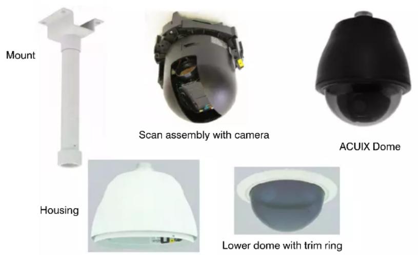
Table 1-1 ACUIX Series Terminology
| Term Definition |
| dome The complete installed product including the housing, mount, bracket or adapter, lower dome, and the scan assembly. |
| scan assembly The combination of firmware, electrical and mechanical components including the camera and lens. The scan assembly is installed into the housing and enclosed by a lower dome. The scan assembly is a component of a dome. |
| camera The particular model camera purchased. The camera is a component of the scan assembly. |
| housing The in-ceiling, indoor or outdoor pendant and surface mount, or rugged upper enclosure. The housing contains the interface board that determines the type of ACUIX installed (analog, digital or fixed). Housing is a hardware component of the dome. |
| mount The hardware used to mount the housing to the applicable surface (for example, a ceiling or wall). The mount is a hardware component used with a specific type of housing. It may be included with the housing (for example, the rugged or in-ceiling domes), or purchased separately (for example, the indoor or outdoor pendant domes). |
| lower dome The clear or colored enclosure that covers the scan assembly and attaches to the housing. It also includes the trim ring. The lower dome is a hardware component of the dome. |
Configuration Options
About the On-Screen Display (OSD) Menus
All ACUIX Series domes provide access to on-screen display (OSD) menus to set various display, control, diagnostic and camera parameters based on user requirements. The OSD is also where mimic tours, privacy zones, sectors, presets and preset tours are programmed. To access the OSD with the ACUIX analog PTZ dome requires a monitor and controller.
About Rapid Eye Installations
When an ACUIX dome is network connected to a PC-based DVR (such as the Honeywell Rapid Eye™) and set to the IntelliBus™ protocol, you can:
Download a dome configuration to a PC for later use: After completing the user programming of the ACUIX unit (presets, mimic tours, preset tours, and privacy zones), you can upload the configuration data to a PC for safekeeping.
Upload a configuration to another dome of the same camera model: The configuration can be saved on a PC and uploaded to a replacement dome if required. The ACUIX configuration has camera model specific parameters so the configuration uploads (retrieving data from a faulty dome) and downloads (sending data to a new dome) must be between two ACUIX units with the same camera model.
Upgrade the firmware to one or more domes in your network.
For detailed information about these options using the IntelliBus protocol, refer to the Rapid Eye System Administrator's Guide.
ACUIX Feature Descriptions
See Configuring the ACUIX Dome on page 67 and the index for instructions related to each of these features.
Contacts
Note
The terms contact and alarm are used interchangeably to mean the same thing. Alarm is currently displayed on the OSD, although contact is a more accurate description as it is not an audible alarm but a change in electrical state to the contacts, which results in a programmed response.
Contacts can detect a door opening or window breakage, for example. Using the on-screen display (OSD), you can program up to four normally open or closed conditions to activate a preset, preset tour, or mimic tour.
Flashback
Use the Flashback feature to toggle between two saved positions and quickly return to a scene of interest.
Flashback is available using a controller. When you press Flashback, it saves the scene (Scene A) as a Flashback. When you move to the next scene (Scene B) and press Flashback again, it saves Scene B and returns the dome to Scene A. If the operator presses Flashback a third time (without manually moving to a new scene), the dome returns to Scene B. The dome only saves and toggles between two scenes at a time, except when Flashback is used during a preset tour.
Mimic Tours
A mimic tour saves the pan, tilt, and zoom commands performed by a user. When a mimic tour is started, the dome replays the saved commands. A mimic tour is useful when operators are interested in scanning slowly to a particular area on a regular basis. You can program up to 16 mimic tours up to 120 seconds (two minutes) each.
Presets
Note Presets are called PreShots on some controllers.
The ACUIX supports up to 150 custom presets when using IntelliBus™ or Diamond protocols; 132 with MAXPRO-mode, or 99 with VCL protocol. There are two types of presets: (1) A special preset or shortcut to a function, for example, opening the OSD menus and (2) an operator created/programmed set of commands (pan, tilt, zoom, focus, and iris setting). The programmed preset is recalled in response to a contact or set as the default function when the dome is idle for a specified time. Other facts about presets include:
- Individual presets can also be part of preset tours.
• Each preset can have a 24-character alphanumeric name. - With the ACUIX analog domes, presets are dependent on the protocol being used.
- By default, the preset name/number for configured presets displays in the top left corner of the screen.
Preset Tours
With preset tours the dome moves from one preset position to another. During the tour, the dome moves between presets at a set velocity (between 1 to 480 degrees per second) and stays for a specified time interval (the dwell) before moving to the next preset. The dwell time can be set between 1 to 99 seconds.
Up to 16 preset tours, each with up to 64 presets, can be programmed for every dome. Preset tours can be started by an operator, in response to a contact, or programmed as a default function when the dome is idle for a specified amount of time. The preset tours are useful for looking at specific locations like doors and windows or to do a scan of each location for a few seconds before moving on. Operators can run the preset tour once or continuously.
Privacy Zones
Privacy zones enable operators to restrict the view in a specific area, for example private property, windows visible across alleyways, swimming pools, or dressing rooms. Up to 32 privacy zones can be configured per dome. Another application is if an automated teller machine (ATM) is being monitored. The view of the ATM screen can be restricted by configuring it as a privacy zone.
A mask (a dark colored box) covers the video display when the dome registers a privacy zone. If there is a preset name, it displays over the video display when privacy zones are hidden. Privacy zone data is stored in nonvolatile memory, which saves the data when the dome is not powered. The privacy zones can be password protected.
The use of a privacy zone password or PIN is available depending on the protocol:
- For MAXPRO-mode, VCL, VCL UTC, Pelco P and Pelco D protocols, privacy zone programming is protected by a four digit numeric PIN. The default PIN is 1000.
- Diamond/IntelliBus: Up to 24-alphanumeric characters can be programmed as a password. The default password is a blank line.
Sectors
Sectors are used for labeling up to 16 areas monitored by a dome. For example, when you are monitoring an exit door, you can add a label in the video display as ExitDoor. After labeling, whenever the dome is positioned to monitor the exit door, the label ExitDoor displays on the monitor.
The sectors can also overlap. If the operator positions the dome where one or more programmed sectors overlap, the dome sequences between the sector titles on the video display for 1.5 seconds per sector.
Still Shot (Freeze)
There are two uses for the Still Shot feature.
- A freeze-frame of video can be made between the presets in a tour. This freezes the video while the ACUIX dome is moving. This results in an effect similar to a video switcher switching between different cameras.
- The operator can freeze the video manually and it remains frozen until the operator unfreezes it.
When the video is frozen, an asterisk displays on the same line as the dome ID, and the video remains frozen on the current scene until the operator unfreezes the video. If the dome ID display is turned off, the asterisk displays by itself.
Camera Model Dependent Features: EIS, TDN and WDR
The camera model (see Scan Assembly Model Numbers and Camera Specifications on page 110) installed with the ACUIX dome changes how various items are configured or set up using the OSD.
Electronic Image Stabilization (EIS)
Electronic image stabilization (EIS) reduces blurring of the camera image caused by vibration from external sources such as wind and roadway traffic. This reduction is done by digitally moving the image to counteract the actual physical movement of the camera.
When EIS is enabled, the camera reduces the area of the CCD that is scanned. This causes the video displayed on the monitor to appear to have zoomed in. When the dome undergoes a pan or tilt operation, EIS is disabled while the dome moves, and then re-enables after the dome stops moving for a five second period.
This is available with the HDXG camera.
True-Day/Night (TDN)
When the light level drops too low for a camera to accurately catch objects in color, the True Day/Night (TDN) feature automatically moves the IR cut filter out of the optical path and switches to black and white mode. A TDN camera captures more detail in low light by using ambient infrared light or external IR sources. On the OSD the term NightShot means the same as TDN and this type of camera is required to make configuration changes.
Note
The focus changes when the IR cut filter is removed. Therefore, when a preset is programmed during the day it may be out of focus at night when the IR cut filter is removed. The only way around this is to have day presets and night presets.
Available with the HDXJ, HDXF and HDXG cameras.
Wide Dynamic Range (WDR)
Wide dynamic range (WDR) allows for proper exposure of an entire scene, even one which has very bright and very dark areas or one in which a portion of the scene is brightly backlit. WDR is perfect for lobbies, loading docks, and ATMs. WDR scans the video and sets the exposure level so it is balanced between the bright areas and dark areas.
The ACUIX domes with WDR scan each frame twice - once very quickly with a short shutter time for the bright areas and again at near normal speed with a slower shutter time for the dark areas. The two scans are then combined to yield a frame where the bright areas come from the fast scan and the dark areas come from the slower scan.
Available with the HDXJ, HDXF and HDXG cameras.
Introduction to the ACUIX PTZ Dome
Preparing to Install the ACUIX Dome
In this section:
• Cabling Recommendations and Cautions, page 25
• About the RJ45 Ethernet Connection, page 25
• General Cautions and Notes for All Cable Installations, page 26
• Maximum Cabling Distances, page 26
• Power Distances and Supplies, page 27
• Video CAT5 or Coaxial Cables, page 28
• Coax Control, page 29
• RS485 Twisted-Pair Telemetry, page 30
Cabling Recommendations and Cautions
Cable preparation should be completed prior to the installation. Each dome requires 24V AC at 1 A. The power supply should be located as close to the dome as possible for service and electrical isolation purposes.
If required, refer to other hardware installation guides to determine cabling requirements based on the individual configuration.
For all types, see Step 5: Connect the Field and Terminal Block Wiring, page 51.
About the RJ45 Ethernet Connection
The RJ45 connector located on the housing interface board is for production use and permits the firmware updates using a crossover cable and a PC. Honeywell Systems Group recommends you DO NOT connect your network to the RJ45 connector. It does not damage the dome, but may negatively affect the network.
General Cautions and Notes for All Cable Installations

- Faulty cable or wiring can cause all domes to fail or malfunction.
- If several domes are powered from a single power source (multiple tap) and noise is experienced on the UTP video output or coax video, then an isolated power supply should be used to correct the problem.
- Never run the cables close to potential sources of electromagnetic interference such as motors, dimmers, and high-speed data trunk cables.
- For CE compliance, the power supply must be connected to a CE-approved 240V UPS (uninterruptible power supply). See below for a list of the power supplies which must be used to meet FCC and UL requirements.
Note For all cables:
- The quality and specification of any cable used has a direct effect on the quality of the video signal at the control equipment end of the system. Compromising the cable quality and specification can lead to poor video quality and system performance.
- When other cables cannot be avoided, run cables perpendicular to each other, not alongside, and keep this distance as short as possible.
Maximum Cabling Distances
Note The terms shielded and unshielded are interchangeable with screened and unscreened, respectively.
Note Unshielded Twisted Pair (UTP) is a general term for all cabling systems used for transmission of data and providing connectivity on a network via a UTP cable. A UTP cable can contain multiple pairs of twisted cables. Commonly used for telephone cabling and 10BaseT and 100BaseT networks using CAT5, CAT5E, CAT6 cables.
See Table 2-1 for the recommended cables and maximum distances for proper operation of the dome. Where applicable, use Category 5 (CAT5) cables or higher.
Table 2-1 Recommended Cables and Maximum Distances
| Type Recommended Cable Maximum Distance | ||
| Power 18 AWG 2-conductor See gauge chart for each unit | ||
| Video Coaxial cable - RG59/U | 1000 feet (305 meters) | |
| Connector - BNC crimp on for RG59/U | ||
| Unshielded | CAT5 or better | 1200 feet (366 meters) |
| Twisted Pair | 1 twisted pair for data | |
| (UTP) Video | 1 twisted pair for video | |
| Data One shielded twisted pair, RS485 cable, can also be UTP CAT5 or better | 4000 feet (1219 meters) | |
| Contact (Alarm) | 20 gauge unshielded twisted pair 10,000 feet (3048 meters) | |
Power Distances and Supplies
The indoor ACUIX requires a 24 VAC power supply at 1.9A, measured at the dome. The outdoor ACUIX requires a 24 VAC power supply at 2.5A, also measured at the dome.
See the following tables to determine the wire sizes and maximum distances for one power source for one ACUIX and the required power supplies for CE compliance.
Table 2-2 Wire Gauge Required for Maximum Distances in a 24 VAC Dome
| AWG 24 VAC Dome (1.9A) 24 VAC Dome with Heater and Blower (2.5A) | |
| 22 39 feet (11.8 meters) 30 feet (9.1 meters) | |
| 20 62 feet (18.9 meters) 47 feet (14.3 meters) | |
| 18 99 feet (30.2 meters) 75 feet (22.9 meters) | |
| 16 157 feet (47.9 meters) | 120 feet (36.6 meters) |
| 14 250 feet (76.2 meters) | 190 feet (58 meters) |
| 12 328 feet (100.0 meters) | 302 feet (92 meters) |
Table 2-3 Recommended Power Supplies
| Description |
| 16 output, 24 VAC, 8 A, SmartFused |
| 8 output, 24 VAC, 4 A, SmartFused |
| 4 output, 24 VAC, 4 A, SmartFused |
| Single output, video, data and power protection, NEMA 4 enclosure |
| Single output, video, data and power protection, indoor enclosure |
| 2" pole mounting kit for HPTV2401WPZ |
| 3" pole mounting kit for HPTV2401WPZ |
| 4" pole mounting kit for HPTV2401WPZ |
Video CAT5 or Coaxial Cables

- Always keep coaxial cables away from all other cables and run them in complete isolation wherever possible.
- If running a separate CAT5 cable specifically for CCTV, ensure it is clearly identified to prevent confusion with network and other structured cabling.
- Use Krone type junction boxes where CAT5 joints are necessary. These boxes are supplied with labeling for all terminals. A special tool is required to insert cables into Krone junction terminals.
Video Coaxial Cable
Table 2-4 Typical 75 Ohm Coaxial Cable Specifications
| Type Conductor Outer Diameter | Application |
| North America | |
| RG11 1/1.63 mm 10.3 mm Used for long drops and underground, also available in versions for plenum use | |
| RG59 1/0.58mm 6.2 mm Main internal cable runs. May also be used externally in containments or when damage is unlikely. Not very flexible. | |
| RG179 7/0.10 mm 2.54 mm Used for shorter drops, higher attenuation but is flexible | |
Table 2-4 Typical 75 Ohm Coaxial Cable Specifications
| Type Conductor Outer Diameter | Application |
| Europe | |
| RG59 1/0.58mm 6.2 mm Main internal cable runs. May also be used externally in containments or when damage is unlikely. Not very flexible. | |
| URM70 7/0.19mm 5.8 mm Patch cables from main runs to equipment. Equipment interconnection. Flexible and useful for tight bends. | |
| CT125 1/1.2mm 7.8 mm Duct/containment rated cable for external main cable runs. Some grades are suited for direct burial. | |
Video CAT5 Cable (UTP Transmission)
CAT5 cabling for video transmission allows multiple domes to be transmitted down the same multicore CAT5 cable without dome video interference or crosstalk. Requires one wire pair per dome. It can support up to four domes on a single CAT5 cable.
Adhere as closely as possible to the following recommendations when installing with CAT5 cable and UTP receiving equipment.
- A UTP receiver module must be used at the control end of the system for every dome that is transmitting video via CAT5. A UTP hub can be used to receive up to 16 domes using CAT5 cable.
- PTZ telemetry is possible when a passive UTP receiver module or hub is used at the control end of the system. If an active receiver is used at the control end of the system, then RS485 telemetry must be used. This requires another single twisted pair per dome.
- When wiring via twisted pair, always ensure that you are actually using a twisted pair by examining the cable. Failure to use wires from the same pair leads to noise introduction and subsequent video and telemetry problems.
- The twisted pair cable used must not be shielded/screened in any way, either by foil, braided shield, or any other means. The use of any cable other than unshielded twisted pair (CAT5 or better) may lead to a reduction in performance and is solely the responsibility of the installer.
Coax Control
The ACUIX domes support telemetry control over coaxial cable. The dome must be set to VCL UTC for coaxial telemetry.
Up-the-coax operation of up to 1000 feet (300 meters) is possible with the appropriate coaxial cable.
RS485 Twisted-Pair Telemetry

- Star wiring configurations are acceptable with the use of a code distribution unit such as Honeywell HDCD8TP.
- Always keep RS485 data cables away from all other cables and run them in complete isolation whenever possible.
- Couple all data cable shields to data ground at the control point end only. The cable shields should not be connected at any other point.
- Connect the cable shield at the controller and connect the cable shield through any junction boxes installed, but do not connect the cable shield to the dome.
When using RS485 twisted-pair telemetry, the video signal is transmitted via a coaxial or CAT5 twisted pair cable and the control data (telemetry) information is a twisted-pair cable.
RS485 twisted-pair telemetry cabling is installed and wired as a network that consists of one or more daisychains. When more than one daisychain is installed, an RS485 telemetry distribution unit must be installed to broadcast telemetry data across the entire RS485 network. Multiple distribution units can be installed on the RS485 network to allow for complex wiring arrangements.
Most RS485 cable is 24 AWG—a 20-gauge unshielded twisted pair (UTP) cable is recommended. The UTP cable is a single twisted-pair with an overall shield and can be used in a daisychain up to a maximum of 4000 feet (1219 meters). These cables are available in a series of overall outer sheaths from standard internal usage finishes to external containment and direct burial types and must have less than 20 pF/ft (picorfarads per foot) of mutual pair capacitance (capacitance between the two conductors in one pair). The mutual pair capacitance should be uniform throughout the length of the cable.
Installing the ACUIX Dome
Note Review Preparing to Install the ACUIX Dome, page 25 before continuing.
In this section:
• Installation Warnings and Cautions, page 31
• DIP Switch Default Settings and Locations, page 32
• Step 1: Set the Switches on the Housing Interface Board, page 34
• Step 2: Set the Switches on the Scan Assembly Circuit Board, page 38
• Step 3: Install the Mount, Adapter or Bracket, page 41
• Step 4: Install the Housing, page 47
• Step 5: Connect the Field and Terminal Block Wiring, page 51
• Step 6: Install the Scan Assembly into the Housing, page 55
• Step 7: Install the Lower Dome onto the Housing, page 56
• Step 8: Configure the Dome, page 57
Installation Warnings and Cautions

All installations must be performed by qualified technical personnel and must be in accordance with all national and local mechanical and electrical codes.
Ensure the mounting surface and installation hardware can hold the combined weight of the scan assembly, housing, lower dome and mount.
To prevent damage to the interface board, follow standard industry precautions for electrostatic discharge-sensitive devices.

- To make good wire contact and ensure the wire does not short to adjacent wires, fully insert the wire in the hole on the terminal strip.
- A good earth ground must be connected at J1, pin 2. Surge suppression is not provided if the unit is not connected to a good earth ground.
- Ensure there are no bare wires touching or faulty operation may occur.
- Ensure the cabling does not interfere with the rotation of the scan assembly.
- To maintain 24 VAC ± 10% at each dome, the proper wire size for the distance and the number of domes must be determined.
- For CE compliance, the power supply must be connected to a CE approved 240V UPS (uninterruptible power supply). See Preparing for Installation for a list of the power supplies which must be used to meet FCC and UL requirements.
DIP Switch Default Settings and Locations
Table 3-1 Default DIP Switch Settings
| Setting Default Switch and Available | Positions | Switch Location | |
| RS485 Termination Not terminated SW1 Housing Interface | Board | ||
| Video Selection Switch OFF SW2 Housing Interface | Board | ||
| Baud rate 9600 SW6, positions 1 to 4 Circuit Board | |||
| Parity Even SW6, positions 5 and 6 Circuit Board | |||
| Protocol MAXPRO-mode | SW5, positions 1 to 5 Circuit Board | ||
| Address | 1 | SW1, SW2, SW3 and SW4 | Circuit Board |
| Miscellaneous Defaults* | |||
| Reserved | OFF SW6-8 | Circuit Board | |
| Restore Factory Defaults | OFF SW5-7 | Circuit Board | |
| Overriding the Logical Address | ON | SW5-8 | Circuit Board |
| Debugging/boot control | OFF SW6-7 | Circuit Board | |
* These are advanced switch settings and it is not recommended to make changes to these defaults. See the System Administration section for more information.
Figure 3-1 Typical DIP Switch Settings by Protocol
| Protocol | Baud and Parity Description | SW6 - Baud and Parity Settings | SW5 – Protocol Setting | ||||||||||||||
| 1 | 2 | 3 | 4 | 5 | 6 | 7 | 8 | 1 | 2 | 3 | 4 | 5 | 6 | 7 | 8 | ||
| IntelliBus 3840 | 0 baud, no parity OFF ON | ON | OFF | OFF | OFF | OFF | OFF | OFF | OFF | OFF | OFF | OFF | ON | ||||
| MAXPRO* 960 | 0 baud, even parity* OFF O | FF | ON | OFF | ON | OFF | OFF | OFF | ON | OFF | OFF | OFF | ON | ||||
| VCL - RS485 | 9600 baud, no parity | OFF | OFF | ON | OFF | OFF | OFF | OFF | OFF | ON | ON | OFF | OFF | OFF | OFF | OFF | ON |
| VCL UTC | 9600 baud, no parity | OFF | OFF | ON | OFF | OFF | OFF | OFF | OFF | OFF | OFF | ON | OFF | OFF | OFF | OFF | ON |
| Diamond | 9600 baud, even parity | OFF | OFF | ON | OFF | ON | OFF | OFF | OFF | ON | OFF | OFF | OFF | OFF | OFF | OFF | ON |
| Pelco P | 4800 baud, no parity (default for P-type control) | ON | ON | OFF | OFF | OFF | OFF | OFF | OFF | ON | OFF | ON | OFF | OFF | OFF | OFF | ON |
| Pelco D | 2400 baud, no parity (default for D-type control) | OFF | ON | OFF | OFF | OFF | OFF | OFF | OFF | OFF | ON | ON | OFF | OFF | OFF | OFF | ON |
* defaults
Step 1: Set the Switches on the Housing Interface Board
Figure 3-2 Pendant, In-ceiling, and Rugged Housing Interface Boards
Rugged HousingPendant Housing In-ceiling H
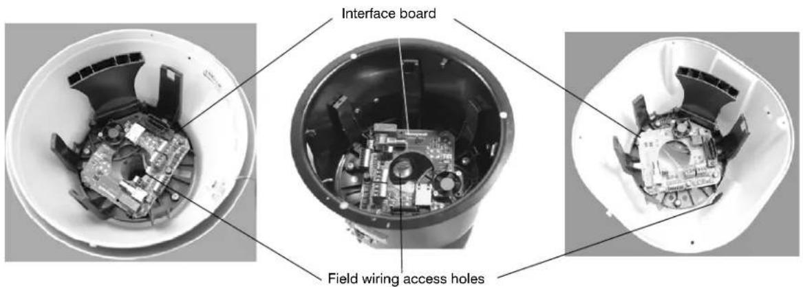
Figure 3-3 Housing Interface Board Layout
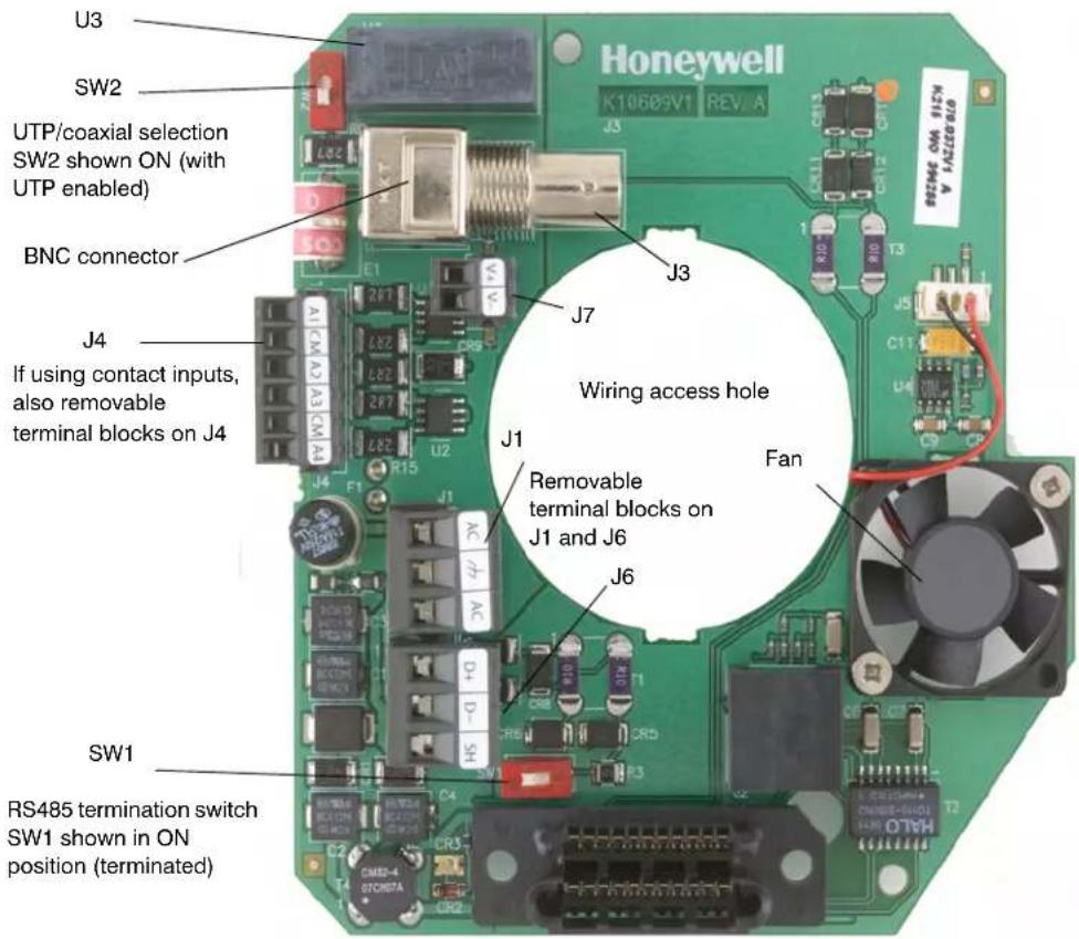
Setting the RS485 Control Data Termination (SW1)
About RS485 Termination

For the RS485 daisychain wiring, the data cable shield should be carried through all units by connecting the cable shields together. Connect the cable shield at the control unit.
RS485 communication is terminated using switch SW1, located near terminal strip J1, pin 3.
One pair of shielded twisted pair RS485 wire or one pair of unshielded twisted pair wire can be used for RS485 data.
- Two domes can be home run connected to each control output with both domes terminated. This is a daisychain with two domes and on control output in the middle.
- The data lines can be daisychain wired (see Figure 3-4 and Figure 3-5) from the control output. Daisychain wiring consists of up to 32 domes per data run with the control output at one end of the run or in the middle of the run.
- If the control output is at the end of the data run, the last dome on the end of the data run must be terminated and all intermediate domes unterminated.
- If the control output is in the middle of the data run, the last dome on both ends must be terminated, and all intermediate domes unterminated.
Note
Each RS485 port on the HDCC8TP must be treated individually as if each one is on a separate piece of equipment.
Figure 3-4 RS485 Daisychain Wiring: Controller at One End
Figure 3-5 RS485 Daisychain Wiring: Controller in the Middle
flowchart
graph TD
    A["SW5 ON"] --> B["Dome 1 Terminated"]
    C["SW5 OFF"] --> D["Dome 2 Not terminated"]
    E["SW5 ON"] --> F["Last dome Terminated"]
    G["Domes 3 to 31 Not terminated"] --> H["Control equipment"]
How to Set the RS485 Control Data Termination
- Locate SW1 on the housing interface board.
-
Carefully place the switch in the required termination position:
-
(Default) To keep the setting as not terminated, place switch away from ON.
• To terminate in 120 Ohm, place switch ON.
Selecting Video Over Coaxial Cable or Unshielded Twisted Pair (SW2)
Control Over Coaxial Cable

For control over coaxial cable, the dome must be set to VCL video telemetry (control over coax) protocol and must be controlled using an HMAX082 or HMAX162 control unit and HKJMMTP joystick controller.
The control equipment adds the data signal to the video coaxial cable. In this case, there are no connections made at data+ and data- on the terminal strip J1.
Video Over Coaxial Cable: Coax Video Enabled
The video must be terminated in 75 Ohm at the last video device. If the video is not terminated or is double terminated, the resulting picture is poor and ghosting is displayed.
Video Over Unshielded Twisted Pair: UTP Video Enabled

The video on the UTP wire cannot be daisychained.
If the UTP option is selected, the video is run on UTP wire and the BNC connector is not used. The video is connected at terminal strip J7, pins 1 and 2. A UTP-compatible receiver is required at the monitor to view and/or record the images.
The video lift and gain settings can be adjusted through the OSD menus to compensate for cable distances over UTP wiring. See Table 3-2 and Table 3-3 for lift and gain settings for cable lengths.
Table 3-2 Recommended Lift Settings for Cable Lengths
| Cable Length Lift Setting |
| 1200+ ft (365+ m) 100 |
| 900 ft (275 m) 80 |
| 600 ft (183 m) 40 |
| 300 ft (91 m) 25 |
Table 3-3 Recommended Gain Settings for Cable Lengths
| Cable Length Gain Setting |
| 1200+ ft (365+ m) 55 |
| 900 ft (275 m) 42 |
| 600 ft (183 m) 35 |
| 300 ft (91 m) 25 |
How to Select Video Over Coaxial Cable or UTP
-
Locate SW2 on the housing interface board.
-
If required, change from the OFF default by carefully placing the switch in the required video selection position:
-
(Default) To keep the Coax Video Enabled, keep switch OFF (away from ON). Unshielded twisted pair (UTP) video balun disabled, to be used with normal 75 Ohm coax video operation.
- To enable UTP Video, place switch ON. UTP video balun enabled, to be used with 120 Ohm UTP video operation.
Step 2: Set the Switches on the Scan Assembly Circuit Board
Figure 3-6 (1) Circuit Board and Switch Locations (2) DIP Switch Example
Setting the Baud Rate, Parity and Protocol (SW5 and SW6)

Leave SW5-8 ON. Setting the DIP switch SW5-8 to OFF enables a user to change the address, protocol, baud rate and parity from the OSD menu (which is not recommended with most installations).
Note
If there are invalid protocol or baud settings on SW5 or SW6 the system defaults to MAXPRO-mode at 9600 baud rate.
- Set the protocol on switch SW5 in the required positions using Table 3-4. MAXPRO-mode is the default.
- Set the baud rate and parity on switch SW6 in the required positions using Table 3-5. 9600 baud and even parity are the defaults.
Table 3-4 DIP Switch SW5 Protocol Settings
| Protocol Name Switch Position | ||||||||
| 1 | 2 | 3 | 4 | 5 | 6 | 7 | 8 | |
| IntelliBusTM OFF OFF OFF OFF OFF ON | ||||||||
| MAXPRO-mode | OFF | ON | OFF | OFF | OFF | OFF | OFF | ON |
| VCL - RS485 ON ON OFF OFF OFF ON | ||||||||
| VCL Video Telemetry (Control over Coax) | OFF OFF ON OFF OFF OFF ON | |||||||
| Diamond | ON | OFF | OFF | OFF | OFF | OFF | OFF | ON |
| Pelco P | ON | OFF | ON | OFF | OFF | OFF | OFF | ON |
| Pelco D | OFF | ON | ON | OFF | OFF | OFF | OFF | ON |
Table 3-5 DIP Switch SW6 Baud Rate and Parity Settings
| Baud Rate and Parity Values | Baud Rate Switch Position Parity Switch Position | Other* | ||||||
| 1 | 2 | 3 | 4 | 5 | 6 | 7 | 8 | |
| 600 OFF OFF OFF | ||||||||
| 1200 | ON OFF OFF OFF | |||||||
| 2400 OFF ON OFF OFF | ||||||||
| 4800 ON ON OFF OFF | ||||||||
| 9600 OFF OFF ON OFF | ||||||||
| 19200 ON OFF ON OFF | ||||||||
| 38400 OFF ON ON OFF | ||||||||
| 57600 ON ON ON OFF | ||||||||
| 115200 OFF OFF ON | ||||||||
| None OFF OFF OFF OFF | ||||||||
| Even ON OFF OFF OFF | ||||||||
| Odd OFF ON OFF OFF | ||||||||
| * The defaults for SW6-7 and SW6-8 are OFF. | ||||||||
Setting the Dome Address (SW1 to SW4)

Each dome requires a unique address between 0000 and 9999. The addressing scheme may be restricted due to the limitations of the controller. For example, the HEGS5000/HEGS5001 controllers control dome addresses 1 to 256 whereas the HJZTP control dome addresses 1 to 128.
-
Turn the arrows on rotary switches SW1, SW2, SW3 and SW4 to the number required using Table 3-6 and Figure 3-7 for reference. For example:
-
To set the dome address to CAM 0001, set SW1 = 1, SW2 = 0, SW3 = 0, SW4 = 0.
- To set the dome address to CAM 0125, set SW1 = 5, SW2 = 2, SW3 = 1, SW4 = 0.
Note
If the dome is set to address 0000, it responds to control commands for any address. For example, if an operator sends control commands to address 0002, the dome that has the address 0000 performs the same commands.
Figure 3-7 Circuit Board Address Switches SW1 to SW4
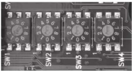
natural_image
Close-up of a printed circuit board with four labeled switches (SW1, SW2, SW3, SW4) and numbered terminals (1–7), no readable text or symbols beyond component markings.Table 3-6 Address Switch Assignments
| Address Value |
| SW1 Units digit |
| SW2 Tens digit |
| SW3 Hundreds digit |
| SW4 Thousands digit |
Step 3: Install the Mount, Adapter or Bracket
Note All the mounting hardware and field wiring is supplied by the installer.
In-Ceiling Housing
This step is part of Step 4: Install the Housing, page 47.
Installing Indoor or Outdoor Pendant Mounts and Adapters
The indoor and outdoor pendant housing has optional mounts and adapters available.
• Wall mount (HDXWM1)
- Pole mount adapter (HDXPMA1)
• Corner adapter (HDXCMA1)
- Parapet or roof mount (HDPRM2)
• Ceiling mount: (HDCM1)
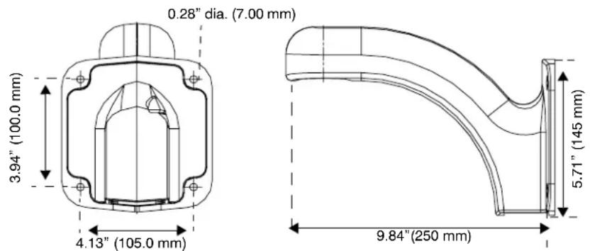
Installing a Wall Mount and Optional Pole or Corner Adapters
The wall mount is designed specifically for the ACUIX dome and can be mounted directly to a vertical load-bearing surface. It supports up to 25 pounds (11.7 kg). The optional corner and pole adapters can be used with the wall mount or with the rugged bracket.
Figure 3-8 Wall Mount Dimensions
- Route field wiring as required through the wall, pendant housing wiring access hole, and then through the wall mount.
Approximately one foot (0.3 m) of cable must extend past the mount for all installations.
- If installing with a corner or pole adapter also route the field wiring through the corner or pole adapter hole.
- (Optional) If you are installing the wall mount with a corner adapter (HDXCMA1) or pole mount adapter (HDXPMA1) then:
Pole Adapter
- Secure the pole mounting bracket to the pole using hardware specifically designed for the surface/material. There are four cutouts (two on each side), 0.24" x 0.75" (6 mm x 19 mm), to accommodate straps to secure the pole mounting bracket to a pole. See Figure 3-9.
Corner Adapter
- Secure the corner bracket using hardware specifically designed for the surface/material. The bracket has eight 0.39" (10.0 mm) holes; four on each side. See Figure 3-10.
-
(Optional): If you are installing with a corner or pole adapter, line up the hole pattern on the wall mount with the hole pattern on the corner or pole adapters.
-
Secure the wall mount to the wall using hardware specifically designed for the surface. There are four 0.28" (7.00 mm) diameter mounting holes for securing the mount.
Figure 3-9 Pole Mount Adapter Dimensions
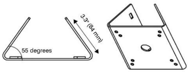
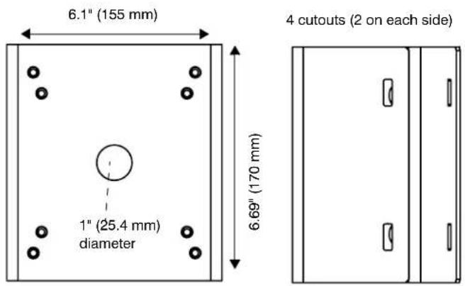
Figure 3-10 Corner Adapter Dimensions
Installing a Parapet or Roof Mount
Note
The parapet and roof mount is designed for installing a dome on the inside of a roof parapet or onto a flat roof surface. The mount has a maximum load rating of 20 pounds (9 kg).
- Route the field wiring through the dome wiring access hole and through the center of the parapet mount.
Approximately one foot (0.3 m) of cable must extend past the mount. - Secure the mount to the parapet or roof using as many of the mounting holes as possible. The minimum recommended is five fasteners on each side of the mounting plate. See Figure 3-11.
Figure 3-11 Parapet and Roof Mount Parts and Dimensions
| 1 Nut and socket | |||
| 2 Mounting arm (2 pc) | |||
| 3 | C | o | u |
| 4 Base plate (x1) | |||
| 5 Support angle (x2) | |||
| 6 Bracket angle (x1) | |||
| 7 | Hexagon head bolt, nuts and spring washers M10 (x12 | ||
| Not shown | Panhead screw M4 x 8 (x2)Set screw M5 x 6 (x3)Wrench head bolt M6 x 30 (x3)Pipe fastener (x1)Hexagon nut M6 (x3)HEX Allen wrench, 2.5 mm (x1)HEX Allen wrench, 5 mm (x1)Flat washer M10 (x12)Teflon seal tape (x1) | ||
Installing a Ceiling Mount
For both indoor and outdoor pendant housings, the ceiling mount is installed directly to a horizontal load-bearing surface and supports up to 25 pounds (11.7 kg).
- Route field wiring as required into the dome wiring access hole and through the center of the ceiling mount.
Approximately one foot (0.3 m) of cable must extend past the mount. - Secure the ceiling mount to the ceiling using hardware specifically designed for the surface.
There are four 0.47" (12.00 mm) diameter mounting holes for securing the mount. See Figure 3-12.
Figure 3-12 Ceiling Mount Dimensions
Installing the Rugged Dome Bracket and Adapters
Note If you are using the optional pole or corner adapters, also see Figures 3-9 and 3-10 respectively.
- Use the hole pattern on the bracket to drill holes in the wall, ceiling or roof. Use the appropriate hardware for the mounting surface.
- (Optional) If you are installing the rugged bracket with a corner adapter (HDXCMA1) or pole mount adapter (HDXPMA1) then:
Pole Adapter
- Secure the pole mounting bracket to the pole using hardware specifically designed for the surface/material. There are four cutouts (two on each side), 0.24" x 0.75" (6 mm x 19 mm), to accommodate straps to secure the pole mounting bracket to a pole.
Corner Adapter
- Secure the corner bracket using hardware specifically designed for the surface/material. The bracket has eight 0.39" (10.0 mm) holes; four on each side.
- (Optional): If you are installing with a corner or pole adapter, line up the hole pattern on the rugged bracket holes as indicated in Figure 3-14 with the hole pattern on the corner or pole adapters.
- Adjust the mounting bracket to any angle from 0^ to 90^ with respect to the housing. The housing must be positioned horizontally and parallel to the floor. See Figure 3-13.
Note To change the bracket orientation, loosen and remove the two bolts that secure the bracket to the housing and slide the bracket along the slot to remove it from the housing.
- If required, secure an installer supplied safety cable to a building support structure. Attach the safety cable (from the building support structure) to the mounting bracket by:
a. Routing the safety around the mounting bracket, then
b. Through a hole in the side of the mounting bracket and then
c. Through the other side of the looping sleeve, and
d. Crimp the looping sleeve to secure the safety cable.
Figure 3-13 Rugged Housing Bracket Adjustment
natural_image
Close-up of a white plastic mechanical component with a magnified inset showing a detail (no text or symbols visible)Figure 3-14 Rugged Bracket Dimensions
Step 4: Install the Housing
ACUIX Power Requirements
• Each ACUIX requires a 24 VAC ± 10% power source measured at the housing.
- For outdoor installations, ensure a 24 VAC at 2.5A power source is available.
• For indoor installations, ensure a 24 VAC at 1.9 A power source is available.
Installing the In-Ceiling Housing (Hard or Dropped Ceiling)
Note The in-ceiling housing field wiring access hole is 1.039 in (26.4 mm) in diameter and accepts 34 in electrical fittings.
The following explains how to install into a dropped (false) ceiling or a hard ceiling. For dropped ceiling installations, use a separately ordered ceiling plate (Honeywell part number 517082-7130). In addition to the other items normally supplied by the installer, the following may be required:
- Tape or plastic channel to prevent dust and material from dropping from the ceiling.
- Safety cable - a 3/32" (approximately 2.4 mm) plastic coated aircraft cable is recommended and a looping sleeve.
Figure 3-15 In-ceiling Housing with Wing Tab Spacing
![Field wiring access hole [1.04" (26.44 mm) diameter] Attach safety cable to bracket Turning screws on wing tabs Wing tabs (x 3) The correct way to space wing tabs](/content/2026/06/1202748/images/1a34accf0efc36f15a3a3cbf3e50c4f45d92d5e8e8e6145ded4e510317c09ba0.jpg)
Figure 3-16 Dropped Ceiling Housing with Ceiling Plate
-
Select the location for the housing.
-
Using the supplied template, cut a 7 5/8" (193.8 mm) diameter hole in the ceiling. If the ceiling is drywall or plaster, it is recommended to seal the entire perimeter of the hole with tape or plastic channel to prevent dust and debris from falling into the dome.
-
If required, secure a safety cable to a building support structure. Attach the safety cable (from the building support structure) to the housing by:
a. Threading the safety cable through a looping sleeve,
b. Attach to the bracket outside the housing.
c. Back through the looping sleeve, and then
d. Crimp the looping sleeve to secure the safety cable.
e. Rotate the safety cable tab as required for ceiling clearance.
- Insert the housing through the hole in the ceiling.
a. Turn the wing tab screws to make sure the space between the wing tabs on the housing and the housing flange is greater than the thickness of the ceiling.
• To increase the space, turn the screw clockwise.
• To decrease the space, turn the screw counterclockwise.
b. Make sure the housing wing tabs are staggered so the tabs are not at the same height and position the wing tabs flat against the housing.
c. Using a Phillips screwdriver, turn the two housing screws clockwise to rotate the tabs out and tighten against the ceiling.
- The recommended maximum torque is 1–1.25 N·m (Newton meters) or 0.74–0.92 lbf·ft (pound-force-foot) or 8.85–11.06 lbf·in (pound-force-inch).
d. Place the ceiling tile, including the dropped ceiling plate (where applicable) and the installed housing on the ceiling grid supports.
Installing the Indoor and Outdoor Pendant Housing
Figure 3-17 Indoor Pendant Housing
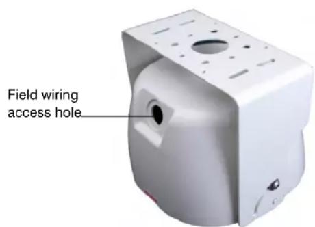
- If not already done, route the field wiring:
• Through the housing mount, then
- Through the field wiring access hole in the housing, and then
- Through the access hole in the interface board installed in the housing.
Note The wiring must extend at least one foot (0.3 m) past the mount for wiring purposes.
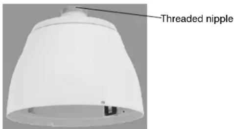
- Install the housing on the mount. Make sure there is Teflon ^® tape on the threaded nipple part of the housing.
Installing the Rugged Housing
Figure 3-18 Rugged Housing and Bracket
- Complete the bracket installation as described previously.
- If not already done, route the field wiring:
a. Through the field wiring access hole in the housing, and
b. Through the access hole in the interface board installed in the housing.
-
Install a 0.75"(19 mm) conduit fitting in the hole on the housing.
-
Place the supplied gasket between the hole in the housing and the conduit fitting to prevent leakage. Tighten the conduit nut to ensure it is water tight.
- Secure the housing to the mounting bracket, previously installed to a ceiling support structure or wall support structure using the appropriate hardware for the mounting surface.
Note The mounting bracket can be at any angle from 0^ to 90^ with respect to the housing. The housing must be positioned horizontally and parallel to the floor.
- To change the orientation of the bracket:
a. Loosen and remove the two bolts that secure the bracket to the housing.
b. Slide the bracket along the slot to remove it from the housing.
Step 5: Connect the Field and Terminal Block Wiring
Terminal Block and PIN Connections

A good earth ground must be connected at the J1 terminal strip, pin 2. Surge, ESD and EMC performance will be compromised if the unit is not connected to a good earth ground.
Figure 3-19 Terminal Block J1 (Power)
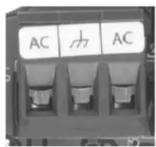
Figure 3-20 Terminal Blocks J6 (Data) and J7 (Video)
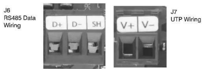
Figure 3-21 Terminal Block J4 (Contacts)
Table 3-7 Terminal Strip Pins and Functions (J1, J4, J6 and J7)
| Terminal Strip J1 Function |
| Pin 1 24 VAC input A |
| Pin 2 ESD (electrostatic discharge) grounding |
| Pin 3 24 VAC input B |
| Terminal Strip J4 Function |
| Pin 1 Contact 1 (A1) |
| Pin 2 Contact common (CM) |
| Pin 3 Contact 2 (A2) |
| Pin 4 Contact 3 (A3) |
| Pin 5 Contact common (CM) |
| Pin 6 Contact 4 (A4) |
| Terminal Strip J6 Function |
| Pin 1 RS485 data (+) communication signal |
| Pin 2 RS485 data (-) communication signal |
| Pin 3 Shield (SH) |
| Terminal Strip J7 Function |
| Pin 1 Video + (V+) (UTP wiring) |
| Pin 2 Video - (V-) (UTP wiring) |
Connecting the Wiring
Note Use the above tables and figures as references during installation.
- Route the field wiring ((data, power, video, contact):
a. Through the field wiring access hole in the housing, and
b. Through the access hole in the interface board installed in the housing.
Note At the appropriate time during the installation, ensure the field wiring access hole is sealed to prevent anything from getting inside the housing.
- Remove the plug-in terminal blocks on terminal strips J1 (24 VAC) and J6.
- (Optional): If required, set up the contact (alarm) input terminal block:

All contact input connections MUST be passive contacts.
Note The terms contact and alarm are used interchangeably to mean the same thing. Alarm is currently displayed on the OSD, although contact is a better description since it is not an audible alarm but a change in electrical state to the contacts resulting in a programmed response.
a. Remove the plug-in terminal block on terminal strip J4.
b. Connect a twisted-pair cable from each peripheral contact to each input at the number terminal and the common terminal on terminal strip J4. The contact is a dry contact between the terminal and the common terminal. The contacts can be configured as normally open (NO) or normally closed (NC).
Note The common terminals are doubled up.
Note The contact cabling should not be terminated until standard operation of the dome is tested.
c. Configure the contacts as required.
- Loosen the screws on the terminal strip and insert the 24 VAC power wires, data wires, video wires (if UTP is selected) and contact wires in the correct positions on terminal strips J1, J4, J6, and J7. See Terminal Block and PIN Connections, page 51.
- Ensure the yellow labeled terminal strip is plugged into the yellow labeled connector and the white labeled terminal strip is plugged into the white labeled connector.
Note Both terminal strips J1 and J6 accept 26–12 AWG wire. If larger or smaller field-run wire is required, a 26–12 AWG wire must be spliced onto the field wire for insertion into the terminal strip.
Note Ensure the correct connections are made with terminal strip J6 - RS485 data (-) and data (+) otherwise polarity can be an issue.
Note You can connect the data cable shield to Pin 3 (SH) on terminal strip J1. Use this connection for looping the shield through to the next dome in the daisychain. It is not connected to the housing interface board.
-
Tighten the screw on the terminal strip to secure the wires.
-
Connect incoming coaxial cable to coaxial pigtail on the housing interface board. Tighten the screw on the terminal strip to secure the wiring.
-
Plug the terminal strips into the respective connectors on the interface board. If you are using a coaxial cable for video, connect the field run coaxial cable to J3.
Note When connecting field wiring, connect to either J3 or J7, not to both at the same time.
-
If applicable, secure the wires from the terminal strip and BNC connector together with a wire tire to ensure the cabling does not prevent the secure closure of the housing and lower dome.
-
Feed extra wire and cable up through the hole in the housing and route it so that it doesn't interfere with the scan assembly when it is inserted.
Step 6: Install the Scan Assembly into the Housing
Note Scan assembly installation is the same with all housing types.
- Carefully remove the plastic lens cap from the scan assembly. Do not touch the lens.
- Rotate and line up the scan assembly yellow label to the mounted housing yellow label.
- Gently push the scan assembly into the housing until the two guides on the scan assembly lock/snap into the holes on the housing guides.
- Gently pull down on the assembly to ensure it has properly latched into place.
Figure 3-22 Installing the Scan Assembly into the Housing
Step 7: Install the Lower Dome onto the Housing
Installing the In-Ceiling Lower Dome
- Clip the lanyard to the mounting post inside the housing.
- Align the lower dome tab hooks with the three mounting posts on the housing.
- Twist to lock the lower dome into the housing.
- If applicable, continue the next steps to configure the dome.
Figure 3-23 In-ceiling Housing Lanyard Bracket
natural_image
Close-up of a mechanical component with visible parts and mounting holes (no text or symbols)Clip the lanyard from the lower dome to the bracket inside the housing
Installing the Indoor or Outdoor Pendant Lower Dome
- Clip the lower dome lanyard to the housing bracket.
- Confirm that the o-ring is in place around the lower dome and press the lower dome into the housing
- Tighten the screws to secure the lower dome to the housing.
- If applicable, continue the next steps to configure the dome.
Figure 3-24 Lower Dome with Lanyard Attached to Pendant Housing
Installing the Rugged Lower Dome
- Clip the lanyard on the housing to the mounting post on the lower dome.
- Align the four screw holes on the lower dome with the four holes on the housing.
- Press the lower dome into the housing and turn the security screws using the special hex key provided.
- If applicable, continue the next steps to configure the dome.
Figure 3-25 Lower Dome with Lanyard Attached to Rugged Housing
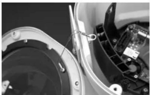
natural_image
Close-up of a mechanical device with internal components and wiring (no visible text or symbols)Step 8: Configure the Dome
Complete these steps:
- Review Before You Begin Configuring on page 59.
- If applicable, continue setting up and configuring other custom settings including camera specific configurations, mimic tours, presets, privacy zones and preset tours using the on-screen display (OSD) and controller. See Configuring the ACUIX Dome on page 67.
- If required or applicable, proceed to user configurations based on other hardware, for example, RapidEye.
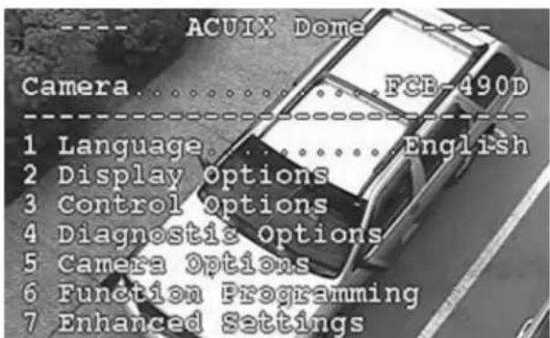
Installing the ACUIX Dome
Before You Begin Configuring
Complete the following before configuring your ACUIX dome:
• Important Information about Controllers and Protocols, page 59
• Step 1: Prepare the Controller and Monitor for Use, page 60
• Step 2: Turn on the Dome and Find the Mechanical Home, page 60
• Step 3: (Optional) Learn about the HJZTP Joystick Controller, page 61
• Step 4: Learn How to Use the Special Presets, page 63
• Step 5: Open the OSD Menu and Start Configuring, page 65
Important Information about Controllers and Protocols
The ACUIX is compatible with the following controllers and protocols:
- HJZTP controller using the VCL, MAXPRO-mode or Diamond protocols
- HMAX082/HMAX162 Matrix Switcher and HKJMMTP controller using VCL UTP / coax control protocol
- Pelco P and Pelco D third party protocols and controllers
- HEGS5000/5001 controller with Diamond protocol
- IntelliBus protocol
In general, protocols allow cross compatibility between products and manufacturers. Because the ACUIX dome is designed to work with a variety of controllers, DVRs and other hardware, deciding what protocol to use when setting up a system is challenging. It is also not possible to describe all the tasks using all combinations of protocols and hardware. Therefore, this guide is a supplement to the hardware users guides and are based on the use of the Honeywell HJZTP joystick controller.
Note
The current HJZTP Controller User Guide indicates it can be set to either VCL or Diamond protocols. The ACUIX default protocol is MAXPRO-mode. For the HJZTP controller ONLY, MAXPRO-mode can be considered exactly the same as Diamond protocol. From the user's perspective, the MAXPRO-mode allows access to the same special presets as with the VCL protocol.
If other controllers, DVRs or protocols are used, MAXPRO-mode, Pelco P or Pelco D protocols also operate in a similar way as described for the VCL protocol. That is to say, how you access the special presets and on-screen display (OSD) is approximately the same.
Step 1: Prepare the Controller and Monitor for Use
Before making configuration changes with any controller, you need to:
- Ensure the dome is assigned to the controller being used. Refer to the applicable controller user guide for instructions.
- Confirm video is displaying on the monitor.
- Confirm there is manual control of the dome using the controller. To manually control an ACUIX and pan, tilt, zoom, focus, and iris, the address must be selected as the control dome. If the dome ID is turned on in the Display Options menu, the letter M is displayed on the monitor.
Step 2: Turn on the Dome and Find the Mechanical Home
The dome locates other referenced positions (such as presets) using a mechanical home (or index) position as a reference point. The dome also needs to locate the mechanical home/index position before responding to the first pan, tilt, and zoom command. For all protocols the operator can send any command to the dome, but what happens when the dome is first turned on depends on options as listed in Table 4-1.
Table 4-1 Display Options at Dome Power Up
| When the dome first powers up | If Then | |
| Start up screen text The startup screen msg is ON | the protocol, baud rate, parity, data bits, camera model, and firmware release dates and versions display on the monitor. | |
| Finding home The dome is set to find home on startup | the message Finding Home... displays on the monitor followed by Home Found... | |
How to Find Home (MAXPRO-mode or Diamond Protocols)
- On the controller, press and hold the Fn key, then press F1.
Note For protocols VCL, VCL UTC, Pelco P and Pelco D there is no command to find home during regular operation.
Step 3: (Optional) Learn about the HJZTP Joystick Controller
The joystick on any controller is used to control the pan and tilt functions. The speed of pan and tilt is relative to the amount of movement applied to the joystick. The following is a brief overview of the operation of the HJZTP controller (Diamond, MAXPRO-mode or VCL protocols available).
For the HJZTP controller:
• the maximum pan speed can be between 120^ , 240^ , or 480^ per second.
- the maximum tilt speed is one-half the maximum pan speed.
- if the maximum pan speed is set to 240^ per second, the maximum tilt speed is set to 120^ per second.
Figure 4-1 HJZTP Controller Layout
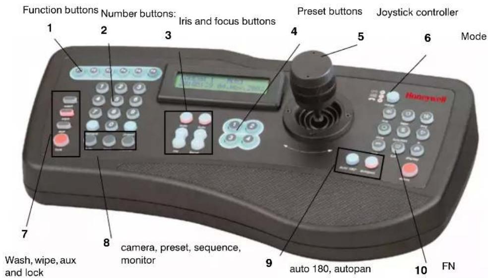
Table 4-2 HJZTP Controller Functions
| No. Button Use | ||
| 1 F1, F2, F3,F4F5 (enter)F6 (menu) | • Move up (F1), down (F2), left (F3)and right (F4)• Press F5 to enter a menu or item.• Press F6 to enter or exit the current menu; In MAXPRO-mode/Diamond mode, it sends the ESC command to the dome. | |
| 2 0 – 9 Press the number corresponding to the submenu or list selection. | ||
| 3 i auto iris | i • Press + (Open) or -/(Close)-to manually change the camera's iris. The camera auto-exposure must be off.• Press auto above the iris control buttons to put the camera in auto-iris mode. | |
| focus + / -auto focus | • Press + (Far) or - (Near) on the controller to manually focus the camera when you zoom in and out.• Use the OSD menus to set auto focus. The auto focus can be set to come on when the camera is zoomed or when the dome undertakes a pan, tilt or zoom action. When the zoom is changed it must automatically focus; optionally when pan, tilt or zoom is changed it must also auto focus. | |
| 4 presets 1–4 Press 1 to 4 preset number to go to a programmed location. | ||
| 5 moveup/down,left/right | Tilt the joystick up or down.Move the joystick left and right to pan.Note If the pan and/or tilt functions of the ACUIX are reversed through the on-screen setup menus (Pan Reverse or Tilt Reverse is enabled), joystick up performs tilt down, joystick down performs tilt up, joystick left performs pan right and joystick right performs pan left. | |
| zoom in/out | Rotate the top of the joystick clockwise to zoom in and counter-clockwise to zoom out. | |
Table 4-2 HJZTP Controller Functions
| No. Button Use | ||
| 6 | mode | Press to toggle between DVR and MUX modes. To toggle between PTZ mode ON and OFF, press and hold Fn, then press the mode button to select PTZ.Note The PTZ domes can be controlled while the controller is in any mode (for example, MUX, DVR, or PTZ). |
| 7 | w a wipe aux lock | •s Press and hold wash to toggle ON and OFF and insert a line.• Press wipe to toggle ON and OFF and delete a line.• Press aux as part of the sequence to open the OSD or while in list menus, to display the next page of items.• Press lock to exit OSD and LCD menus and return the dome and controller to normal operation. |
| 8 | c a preset sequence monitor | mPress a:dom number a ▶camera to select that dome to display on the monitor.• Press preset ▶[preset number] to access presets and tours.• Press sequence to send 'S' to the dome and save settings.• Pressing a number (1 to 4) followed by monitor selects that auxiliary monitor for control by the controller (the spot monitor number is displayed on the LCD). If you press monitor without first entering a number, the controller goes back to the main monitor (MAIN displays on the LCD). |
| 9 auto 180° autopan | • Press auto 180° to view a person walking underneath the dome; pan the dome 180° at the maximum speed.• Autopan is used with presets and tours. | |
| 10 | Fn | • To return to manual control, press and hold Fn, then press F6 (menu). The 'return to manual' command is used to cancel automatic dome actions.• To return to mechanical home, press and hold Fn, then press F1, to send the dome to its mechanical home position. |
Step 4: Learn How to Use the Special Presets
There are several special presets reserved for controlling and programming the dome. Depending on the protocol, approximately 150 presets are available for custom programming. Presets 72–99 are reserved for the available special presets listed in Table 4-3 and described in this guide.
Note
The text displayed on the OSD with MAXPRO-mode is a shortened version of the descriptions in Table 4-3.
Various presets are available for programming with all protocols with exceptions as noted.
Table 4-3 Special Presets Based on Protocol
| Preset Function Protocol | |
| 72 Recover encrypted user login PIN and GUID All | |
| 73 Enable broadcast command receive mode | MAXPRO-mode, VCL, VCL UTC, Diamond, Pelco D or P |
| 74 Disable broadcast command receive mode | |
| 75 Administrator / password/PIN settings• 1. User Login PIN• 2. Change PIN• 5. System Info• 6. Change Address, Protocol | All |
| 76 Run Mimic Tour 1–16 | MAXPRO-mode, VCL, VCL UTC, Pelco D or P |
| 77 Program Mimic Tour | |
| 78 Run Preset Tour 1–16 | |
| 80, 81, 82 Run mimic tours 1, 2 and 3 | |
| 83, 84, 85 Program mimic tours 1, 2 and 3 | |
| 86 Stop or end mimic tour programming sequence | |
| 87, 88, 89 Start/run preset tours 1, 2 and 3 | |
| 90 Setup menu (on-screen display/OSD) | MAXPRO-mode, VCL, VCL UTC, Diamond, Pelco D or P |
| 91, 97 and 99 Reserved | |
| 92 Toggles auto exposure or iris ON and OFF(factory default is ON) | |
| 93 Toggles backlight compensation ON and OFF(preset 92 /auto exposure must be ON) | |
| 94 Toggles between standard operation andNightShot mode (camera dependent) | MAXPRO-mode, VCL, VCL UTC, Pelco D or P |
| 95 Toggles between freezing and unfreezing the video (camera dependent)• P r e► Preset to toggle between freezing and unfreezing the current video scene. | |
| 96 Run the Flashback function• P r e► Preset to toggle between two saved positions and quickly return to a scene of interest. | |
| 98 Camera lens reset or cycles the power (camera dependent) | All |
Accessing Special Presets
- Press [preset number] ▶ Preset button on the controller.
Step 5: Open the OSD Menu and Start Configuring
Note The availability of an OSD menu item is based on both the protocol and the camera model.
Note If the password feature is enabled the Login screen displays first and a password is required to access the OSD.
Opening the OSD with Special Preset 90
Note To access any preset (special or programmed) press [preset number] ▶ Preset button on the controller.
- Enter a password or skip to step 2.
a. If prompted, enter the 4-digit PIN (the default is 1000) to log in as User Level 1. Move the joystick up or down to select numbers for each digit. Move the joystick left or right to move between digits.
b. Press F5 (enter).
- Press 90 ▶ Preset.
The OSD display opens on the monitor.
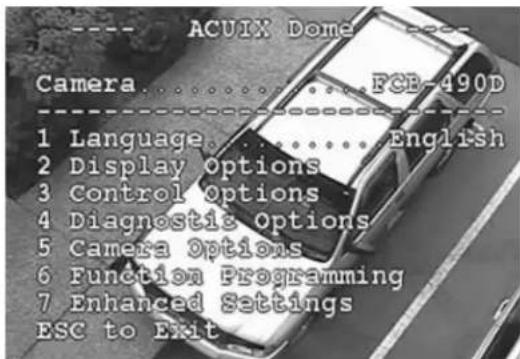
Opening a Submenu or Selecting a Menu
- Press a number beside the menu option. The numbers either toggle between the available choices or opens another menu.
- Move the joystick up or down the menu and press F5 (enter).
Exiting or Escaping from a Menu
Note
Depending on the protocol used, for example with the HJZTP controller, the monitor displays different exit instructions.
To exit or escape from a menu (VCL):
• The monitor displays press Iris Close. Press Iris (-).
In VCL protocol, press Iris (+) to open a menu and Iris (-) to close a menu. The OSD uses the terms Iris Open and Iris Close to mean the same thing respectively. In some menus, you can also use these keys to toggle between values.
Iris open
Iris close
To exit or escape from a menu (MAXPRO-mode or Diamond):
• The monitor displays press Esc. When using an HJZTP controller, press lock.
Configuring the ACUIX Dome
In this section:
- Opening and Displaying the OSD Camera Menu, page 67
- Configuring Display Settings, page 69
- Configuring the Pan, Tilt and Zoom (PTZ) Dome Settings, page 72
- Configuring the Image Quality and Video Display Settings, page 74
• HDXG Cameras: Configuring Camera Settings, page 80
• Configuring Contacts/Alarms, page 83 - Configuring the Controller Settings - Pan and Tilt Reverse, page 85
- Configuring the Lift and Gain Settings and PWM, page 86
• Configuring Mimic Tours, page 87 - Configuring Default Functions: Presets and Tours, page 89
- Configuring Presets and Preset Tours, page 90
• Configuring Privacy Zones, page 93
• Configuring Sectors, page 96
Opening and Displaying the OSD Camera Menu
- Open the OSD by pressing 90 ▶ Preset.
After each step it is assumed that you exit and save after each task using the applicable method based on the protocol and controller.
Figure 5-1 On Screen Display (OSD) Menu Tree
ACUIX On-Screen Display (OSD) Menus
| 1. Language | English (default); Spanish (Espanol); Polish (Polski); German (Deutsch); Italian (Italiano); French (Francais); Dutch (Nederlands); Czech | ||||
| 2. Display Options 3. Control Options | 4. Diagnostic Options ^1 | 5. Camera Options ^1 | 6. Function Programming 7. Enhanced Features | ||
| 1. Camera Msg 1. PASS 1. Coordinates 1. Zoom and Focus 1. PTZ Mimic Tour Menu 1. Video Gain/PWM Settings(1) Max Digital Zoom Mag (1) Run a Mimic Tour (1) Video Gain (UTP)(2) Manual Zoom Speed (2) Program a Mimic Tour (2) Lift PWM Level 0-100Available all cameras(3) Delete a Mimic Tour (3) Gain PWM Level 0-100(4) Char White Level 0-100 | |||||
| 2. Sectors | 2. Auto-Pivot | 2. N/A | 2. Exposure Control(1 or 2) Auto Exposure Level(2 or 8) Backlight Comp | 2. Program a Preset Tour | 2. N/A |
| 3. Preset Names | 3. Program Alarms(1) Program Alarms(2) Set Alarm Condition | 3. Clear the Memory | 3. NightShot Control(1) NightShot Mode(2) NightShot(3) Activate(4) Deactivate | 3. Privacy Zone Options ^1 (1) Change PrivZone Priority(2) Enable/Disable PrivacyZone(3) Privacy Zone Color | 3. N/A |
| 4. Digital Zoom Mag | 4. Set Pan and Tilt Options(1) Manual Speed (deg/s)(2) Pan Reverse(3) Tilt Reverse(4) - 5 deg Tilt Limit(5) Find Home on Startup(6) Pan OffsetOffsetSet Pan Offset(7) Startup State Restore | 4. N/A | 4. White Balance(1) High Light WB Mode(2) Low Light WB Mode(3) Enter High Light 28dB(4) Enter Low Light 28dB(5) Manual White Balance | 4. List PS/PT/Sectors(1) Presets(2) Preset Tours(3) Sectors | 4. N/A |
| 5. Start up Screen Msg | 5. Set Default Function | 5. N/As | 5. Still Preset | 5. Program Sector* | 5. Time and Date Settings(1) Display Time(2) Display Date(3) Time Format(4) Change Time(5) Change Date |
| 6. Change Camera Name Loc | 6. Auto Focus | 6. Restore Default Settings | 6. Vert Phase Edge | 6. Program Privacy Zone* | 6. Display Supply Voltages |
| 7. Change Sector Name Loc | 7. Preset Tour Auto Focus | 7. Scan and Camera Reset | 7. Vert Phase | 7. Delete PS/PT/PZ/Sectors | |
| 8. Crosshairs | 8. Electronic Image Stabilization ^2 | ||||
| 9. Dome Name Settings(1) Set Dome Name(2) Display Dome Name(3) Change Dome Name Location | 9. WDR/Motion Detection(1) Wide Dynamic Range(2) Motion Detection | ||||
1 Feature and menu availability is camera dependent
2 HDXG only
3 MAXPRO-mode, VCL: UTC and Pelco P and D protocols only
Configuring Display Settings
Note This section also includes Enhanced Features menu options.
Note Remember you access the OSD by pressing 90 ▶ Preset.
Task/Action with Default Notes
Changing the On-screen Language
- Scroll to select 1 Language ▶ English (default), French (Francais), German (Deutsch), Italian (Italiano), Spanish (Espanol), Dutch (Nederlands), Polish (Polski).
- Select 2 Display Options ▶4 Digital Zoom Mag ▶ON or OFF (default). Displays the magnification level on the right side beside the dome ID. If the location changes based on dome name, this text also moves.
Task/Action with Default Notes
Changing the Start up Screen Msg
- Select 2 Display Options ▶5 Start up Screen Msg ▶ ON (default) or OFF.
Changing Dome (Camera) Name/Msg Loc (Location)
- Select 2 Display Options ▶6 Change Camera Name Loc ▶ Depending on the protocol, use either arrows or the joystick to move the text up or down the monitor to position as required.
See Note 1 page 71.
Displaying Crosshairs
- Select 2 Display Options ▶8 Crosshairs ▶ON or OFF (default).
Useful with pan offset.
Setting a Dome Name
- Select 2 Display Options ▶ 9 Dome Name Settings ▶ 1 Set Dome Name ▶ enter a 24-alphanumeric name for the dome. Depending on the protocol, use either arrows or the joystick to scroll the number and letter choices.
See Note 2 page 71.
Displaying a Dome Name
- Select 2 Display Options ▶9 Dome Name Settings ▶2 Display Dome Name ▶ON or OFF (default).
See Note 2 page 71.
Changing Dome Name Location
- Select 2 Display Options ▶9 Dome Name Settings ▶3 Change Dome Name Location ▶ Depending on the protocol, use either arrows or the joystick to move the text up or down the monitor to position as required. The default is top left.
See Note 2 page 71.
Displaying the Time
-
Select 7 Enhanced Features ▶ 5 Time and Date Settings ▶ 1 Display Time ▶
-
Select ON to display the time at the lower left center of the monitor in HH:MM:SS (24 hour format) or AM/PM (12-hour format) or OFF (default).
Displaying the Date
-
Select 7 Enhanced Features ▶ 5 Time and Date Settings ▶ 2 Display Date ▶
-
Select ON to display the time at the lower right center of the monitor in DD-MMM-YYYY format or OFF (default).
Task/Action with Default Notes
Setting the Time Format to Display
- Select 7 Enhanced Features ▶ 5 Time and Date Settings ▶ 3 Time Format ▶
- Select 24 hours (default) to display the time as HH:MM:SS or 12 Hours to display the time with AM or PM.
Setting the Time
- Select 7 Enhanced Features ▶ 5 Time and Date Settings ▶ 4 Change Time ▶
- Enter the new time in HH:MM:SS (hours:minutes:seconds) format. The time must be entered in 24-hour format.
- Press Enter to change to the new time or press ESC to leave the time as originally displayed.
Setting the Date
- Select 7 Enhanced Features ▶ 5 Time and Date Settings ▶ 4 Change Date ▶
- Enter the new date in YYYY-MM-DD (year-month-day) format.
- Press Enter to change to the new date or press ESC to leave the date as originally displayed.
Display Options Notes
(1) Applies to the numerical number assigned to each dome (displays on the monitor as CAM) during installation using the address switches on the scan assembly. To name and position the text on the display see Changing Dome Name Location on page 70.
(2) Applies to the user assigned alpha-numeric name you can assign to each dome. The dome may also have a number assigned during installation when the address switch settings are assigned.
Configuring the Pan, Tilt and Zoom (PTZ) Dome Settings
Note
Remember you access the OSD by pressing 90 ▶ Preset.
Task/Action with Default Notes
Turning the Pan and Tilt Speed Range (PASS) ON and OFF
- Select 3 Control Options ▶1 PASS ▶ ON (default) or OFF.
PASS is a function of the lens zoom angle. The maximum pan and tilt speeds are reduced when the lens zooms in. For example, the pan and tilt functions are slow when the camera is set at 12X zoom. The higher the zoom magnification, the slower the speed.
Turning the Auto Pivot ON or OFF
- Select 3 Control Options ▶ 2 Auto Pivot ▶ ON or OFF (default).
Track people passing directly underneath the dome. The dome automatically turns 180^ when it reaches its lower limit. It continues to tilt up as long as the control tilt function remains in the down position. When the dome reaches its tilt up limit, it returns to normal operation.
Changing the Manual Pan and Tilt Speed
- Select 3 Control Options ▶4 Set Pan and Tilt Options ▶1 Manual Speed ▶120°/sec, 240°/sec, or 480°/sec (default).
The maximum tilt speed is half of the maximum pan speed.
Task/Action with Default Notes
| Turning the -5° Tilt Limit ON or OFF | |
| 1. Select 3 Control Options ▶ 4 Set Pan and Tilt Options ▶ 4-5° Tilt Limit ▶2. Select ON to position the unit tilt to 5° above horizontal or OFF (default). | Allows the camera to tilt 5 degrees above horizontal. |
| Finding the Mechanical Home on Startup | |
| 1. Select 3 Control Options ▶ 4 Set Pan and Tilt Options ▶ 5 Find Home on Startup ▶2. Select:OFF (default) to set the unit to find home when powered up and the dome performs a control command.ON to set the dome to find the mechanical home (or index) position after an initial startup delay of 15 seconds.If you selected ON, the message Extreme Caution: This will cause the scan to move immediately on startup... displays.Select Y (yes) to continue or N (no) to cancel. | When a privacy zone is enabled, no video is shown during the finding home process and privacy zones are not recognized until the dome reaches home. Once the dome finds home, a picture can be viewed on the monitor unless a privacy zone overlaps with this home setting. |
| Turning the Pan Offset ON or OFF | |
| Select 3 Control Options ▶ 4 Set Pan and Tilt Options ▶ 6 Pan Offset ▶ 1 Pan Offset ▶ ON or OFF (default). | Pelco P and D protocols only: The pan offset feature is not available due to the preset index starting at 1 instead of 0. |
| Setting the Pan Offset | |
| Select 3 Control Options ▶ 4 Set Pan and Tilt Options ▶ 6 Pan Offset ▶ 1 Pan Offset ▶ ON.Press 0 ▶ Preset.Position the dome where preset 0 is expected to be. If it does not go to the previously known position for preset 0, the offset function cannot be used.Select 3 Control Options ▶ 4 Set Pan and Tilt Options ▶ 6 Pan Offset ▶ 2 Set Pan Offset.Test the setting. Reposition the unit, and select 0 ▶ Preset to confirm it returns to the position programmed. | Pelco P and D protocols only: The pan offset feature is not available due to the preset index starting at 1 instead of 0.For all other protocols, preset 0 is used to define the location of the pan setting; you must know the original positioning of preset 0 to complete these steps.The pan offset feature is useful when a new scan assembly is installed in a dome and you want to transfer programming from the previous scan assembly to the new dome using the upload/download feature. |
Task/Action with Default Notes
Turning the Start Up State Restore ON or OFF
-
Select 3 Control Options ▶4 Set Pan and Tilt Options ▶6 Pan Offset ▶7 Startup State Restore ▶
-
Select
-
OFF (default).
-
ON to set the dome to return to the state of operation at the last loss of power.
-
If you selected ON, the message Extreme Caution: This will move the dome to previous shutdown position on startup... displays.
• Select Y (yes) to continue or N (no) to cancel.
Displaying Pan and Tilt Coordinates
- Select 4 Diagnostic Options ▶1 Coordinates ▶
- Select ON to display the pan (azimuth) and tilt (elevation/declination) along the bottom of the monitor or OFF (default).
Configuring the Image Quality and Video Display Settings
Note The Camera Options menu is highly variable and camera model dependent.

Only qualified technical personnel should use the Camera Options menu to change configurations as these changes can make the recorded images unusable.
Note Remember you access the OSD by pressing 90 ▶ Preset.
Task/Action with Default Notes
Changing the Auto Focus Mode
-
Select 3 Control Options ▶ 6 Auto Focus ▶
-
Select:
-
Z (default) to auto focus the lens when the zoom setting changes.
• OFF to manually focus the lens. - PTZ to auto focus the lens when the pan, tilt, or zoom positions change.
Minimum focus distance is set at 3.3 ft (1.0 meter) from the camera lens in both manual and automatic focus mode. When the zoom is changed it must automatically focus; optionally when pan, tilt or zoom is changed it must also auto focus.
Setting the Maximum Digital Zoom Magnification Level
- Select 5 Camera Options ▶ 1 Zoom ▶ 1 Max Digital Zoom
▶ 1x or 2x or 4x or 12x (default). - For HDXG, if image stabilization is enabled, the digital zoom is restricted to 2x.
Available with all camera models.
Setting the Manual Zoom Speed
-
Select 5 Camera Options ▶ 1 Zoom ▶ 2 Manual Zoom Speed.
-
Select a number to set the speed the joystick moves the zoom lens based on the angle of the joystick is positioned:
-
6 (default)
- 0 is the slowest
- 7 is the fastest
- 8 makes the zoom speed proportional to the angular position of the joystick control.
Available with camera models HDXA, HDXJ and HDXF (NOT HDXG).
Task/Action with Default Notes
Setting the Exposure Level
-
Select 5 Camera Options ▶ 2 Exposure Control ▶ 2 Exposure Level.
-
Select a number, where:
-
0 is for a dark/outdoor application
• 14 is for a bright/indoor application - 7 (default)
Available with all camera models. This explains the steps for HDXA, HDXJ and HDXF. For HDXG cameras, go to the next section.
Turning Auto Exposure ON or OFF
- Press 92 ▶ Preset.
Turning Backlight Compensation ON or OFF
-
Press 92 ▶ Preset to turn auto exposure ON.
-
Press 93 ▶ Preset.
- OR-
Select 5 Camera Options ▶ 2 Exposure Control ▶ 8 Backlight Compensation ▶ ON or OFF (default).
Available with all camera models. This explains the steps for HDXA, HDXJ and HDXF. For HDXG cameras, go to the next section.
Setting NightShot Control (TDN) to Manual or Auto
-
Press 92 ▶ Preset to turn auto exposure ON.
-
Select 5 Camera Options ▶ 3 NightShot Control ▶ 1 NightShot Mode ▶ MAN (default) or AUTO.
Available with camera models HDXJ, HDXF and HDXG (NOT HDXA).
Turning NightShot (TDN) ON or OFF
-
Set NightShot to MAN mode.
-
Select 5 Camera Options ▶ 3 NightShot Control ▶ 2 NightShot ▶ ON to manually moves the IR block filter in and out or OFF.
Available with camera models HDXJ, HDXF and HDXG (NOT HDXA).
Task/Action with Default Notes
Activating NightShot (TDN)
-
Set NightShot mode to Auto.
-
Select 5 Camera Options ▶ 3 NightShot Control ▶ 3 Activate NightShot.
-
Toggle between the available gain and shutter speed values.
a. Gain Settings
- 0dB, 2dB, 4dB, 6dB, 8dB, 10dB, 12dB, 14dB, 16dB, 18dB, 20dB, 22dB, 24dB, 26dB, 28dB.
b. Shutter Speed Settings
- PAL = 1/3 sec, 1/6 sec, 1/12 sec, 1/25 sec, or 1/50 sec.
- NTSC = 1/4 sec, 1/8 sec, 1/15 sec, 1/30 sec, or 1/60 sec.
Available with camera models HDXJ, HDXF and HDXG (NOT HDXA).
Keep the activation and deactivation settings slightly apart to ensure that there is always some deadband between the activate and deactivate levels. The amount of deadband can be adjusted to prevent the dome from oscillating between the NightShot activated and deactivated modes.
Deactivating NightShot (TDN)
- Select 5 Camera Options ▶ 3 NightShot Control ▶ 4 Deactivate NightShot.
- Toggle between the available gain and shutter speed values.
a. Gain Settings
- 0dB, 2dB, 4dB, 6dB, 8dB, 10dB, 12dB, 14dB, 16dB, 18dB, 20dB, 22dB, 24dB, 26dB, 28dB.
b. Shutter Speed Settings
- PAL = 1/3 sec, 1/6 sec, 1/12 sec, 1/25 sec, or 1/50 sec.
- NTSC = 1/4 sec, 1/8 sec, 1/15 sec, 1/30 sec, or 1/60 sec.
Available with camera models HDXJ, HDXF and HDXG (NOT HDXA).
Task/Action with Default Notes
Selecting the High or Low Light WB Mode
1. Select 5 Camera Options ▶4 White Balance ▶
• 1 High Light W B Mode HDXJ and HDXF (NOT HDXG).
• 2 Low Light WB Mode
2. Select:
- AUTO (default) to avoid fixing single color scenes as white. Auto Tracing White Balance with limitations on R and B gain (3,200°K to 6,000°K).
- ATW to turn the dominant color within the temperature color range to white. Auto Tracing White Balance (2,000°K to 10,000K°).
- Indoor to set the white balance to 3200^ .
• Outdoor to sets the white balance to 5800°K.
Selecting a Gain Setting/Shutter Speed for High or Low Light 28 dB
1. Select 5 Camera Options ▶4 White Balance ▶
• 3 Enter High Light 28dB
• 4 Enter Low Light 28dB
- Select a Gain Setting between 0 and 28 dB.
3. Select a Shutter Speed :
PAL cameras (high light default is 1/50 sec; low light default is 1/25 sec)
• 1/3 sec, 1/6 sec, 1/12 sec, 1/25 sec, or 1/50 sec
NTSC cameras (high light default is 1/60s; low light default is 1/30 s):
• 1/4 sec, 1/8 sec, 1/15 sec, 1/30 sec, or 1/60 sec
Available with camera models HDXA, HDXJ and HDXF. (NOT HDXG)
The high light level mode cannot be set lower than the low light level mode and conversely, the low light level mode cannot be set higher than the high light level mode.
Turning the Manual White Balance ON or OFF
1. Select 5 Camera Options ▶4 White Balance ▶ [1 or 5] Manual White Balance ▶
2. Select ON or OFF (default).
- For model HDXG, if set to ON, the red and blue gain settings can be changed. If set to OFF, the red and blue gain settings can be changed but the settings do not take affect until the manual white balance is set back to ON.
Available with all camera models.
For models HDXJ and HDXF, the menu selection is 5 Manual White Balance.
For HDXG, menu selection is 1 Manual White Balance.
Task/Action with Default Notes
| Setting the Red and Blue Gain | |
| 1. Turn Manual White Balance ON.2. Select 5 Camera Options ▶4 White Balance ▶• [2 or 6] Red Gain• [3 or 7] Blue Gain3. Toggle to select a value based on camera model:• For models HDXA, HDXJ and HDXF, select from a range between 0 (low) and 255 (high). The default is 200.• For model HDXG, select from a range between 0 (low) and 511 (high). The default is 128. | Available with all camera models.For models HDXA, HDXJ and HDXF, the menu selection is 6 Red Gain and 7 Blue Gain.For HDXG, the menu selection is 2 Red Gain and 3 Blue Gain. |
| Enabling or Disabling Vertical Phase Edge (Line Lock) | |
| Caution Requires an AC power supply.• Select 5 Camera Options ▶6 Vert Phase Edge ▶ Enabled or Disabled (default). | Available with all camera models.If you enable the Vertical Phase Edge, you can set the Vertical Phase from 0 to 359.9. |
| Setting the Vertical Phase Edge (Line Lock) | |
| Caution Requires an AC power supply.1. Enable the Vertical Phase Edge.2. Select 5 Camera Options ▶7 Vert Phase ▶ enter a number between 0 (default) and 359.9. | Available with all camera models. |
| Turning Motion Detection ON or OFF | |
| 1. Select 5 Camera Options ▶9 Motion Detection.The message This will Disable Motion Detection.Are you sure that you want to do this? displays.2. Select Y (yes) to disable motion detection or N (no) to cancel.3. Select ON or OFF.• If set to ON, interlace scanning, EIS and the default functions are all automatically disabled.• If set to ON and an operator sends a command to the dome, then motion detection is automatically set to OFF and disabled. The operator must access the setup menu to re-enable it.• If set to ON and manual operation is in progress, the feature is disabled for 30 seconds and returns to normal operation after the PTZ operation concludes. | Available with camera models HDXJ, HDXF and HDXG (NOT HDXA).When motion is detected, the message Motion Detected is displayed on the monitor and remains on the video until the dome receives a pan, tilt, or zoom command.Motion detection is automatically disabled as soon as motion is detected to avoid multiple triggers from the same event. The feature is turned on again after a one minute delay of any event.If the dome is in IntelliBus protocol, for each Motion Detect Event an IntelliBus Motion Detect message is sent to the IntelliBus master. |
HDXG Cameras: Configuring Camera Settings
Note The following tasks are applicable only to the HDXG camera models.
Table 5-1 HDXG 35X Camera Feature Dependencies
| If: Then: | |
| Motion detection is enabled Interlace scanning and image stabilization are disabled. | |
| Image stabilization is enabled Motion detection is disabled. | |
| Interlace scanning is enabled Wide Dynamic Range (WDR) and motion detection are disabled. | |
| Wide Dynamic Range (WDR) is enabled | Interlace scanning must be disabled and the ACUIX must be in auto iris mode. |
Task/Action with Default (HDXG Camera Models Only) Notes
Setting the Auto AE Mode
- Select 5 Camera Options ▶ 2 Exposure Control ▶ 1 Auto AE Mode.
- Select from the available settings (see Table 5-2) displayed below the menu options. The default mode is AE.
The controller and the camera must be in auto iris mode.
Table 5-2 Auto Exposure Control Mode Settings
| Setting NightShot | Control | AutoNightShotSensitivity | Digital SlowShutter |
| Auto AE Mode MAN NA OFF | |||
| Auto AER1 Mode AUTO | HIGH | OFF | |
| Auto AER1 Mode AUTO | MID | OFF | |
| Auto AE+ Mode | MAN NA AUTO | ||
| Auto AE+ 1 Mode | AUTO | HIGH | AUTO |
| Auto AER-5 Mode | AUTO | MID | AUTO |
| Auto AER +3 Mode | AUTO | LOW | AUTO |
Task/Action with Default (HDXG Camera Models Only) Notes
| Setting the Manual AE Mode | |
| 1. Select 5 Camera Options ▶ 2 Exposure Control ▶ 2 Manual AE Mode. | The controller must be set to manual iris mode. |
| 2. Select:Iris (default): to control the iris manually where the camera controls the gain and shutter automatically.Gain: to manually control the gain where the camera controls the iris and shutter automatically.Shutter: to control the shutter manually where the camera controls the iris and gain automatically. | HDXG cameras only. |
Changing the Exposure Level
| 1. Select 5 Camera Options ▶3 Video Setup ▶1 Exposure Level. | HDXG cameras only. |
| 2. Enter a number between 0 and 255 where: | |
| • 91 (default) | |
| • 0 = dark | |
| • 255 = bright | |
Changing the Max AGC Level
| 1. | Select 5 Camera Options ▶ 3 Video Setup ▶ 2 Max AGC Level. | HDXG cameras only. |
| 2. | Enter a number between 0 and 255 where: | |
| • 216 (default) | ||
| • 0 = picture is dim with no noise | ||
| • 255 = picture is bright with noise |
Changing the Chroma Level
| 1. Select 5 Camera Options ▶ 3 Video Setup ▶ 3 Chroma Level. | HDXG cameras only. |
| 2. Enter a number between 0 and 255 where: | |
| • 140 (default) | |
| • 0 = n o c o l o r | |
| • 255 = color is saturated | |
Turning Backlight Comp ON or OFF
| 1. Ensure Auto Exposure mode is ON (Press 92 ▶ Preset). | HDXG cameras only. |
| 2. Ensure wide dynamic range (WDR) is OFF (default). | |
| 3. Select 5 Camera Options ▶3 Video Setup ▶4 Backlight Comp ▶ON or OFF (default). |
Task/Action with Default (HDXG Camera Models Only) Notes
Setting the Auto Slow Shutter Limit
| 1. | Select 5 Camera Options ▶3 Video Setup ▶5 Auto Slow Shutter Lim. | HDXG cameras only. |
| 2. | Select NTSC options: 1/60, 1/30, 1/15, 1/8, 1/4 (default), 1/2 |
Turning Wide Dynamic Range (WDR) ON or OFF
| 1. Ensure Auto Iris Mode is ON. | HDXG cameras only. |
| 2. Select 5 Camera Options ▶3 Video Setup ▶6 Wide Dynamic Range ▶ON or OFF (default). |
Turning Interlace Scanning ON or OFF
| 1. | Select 5 Camera Options ▶ 3 Video Setup ▶ 7 Interlace Scanning.The message This will Disable WDR & Motion Detection. Are you sure that you want to do this? displays. | HDXG cameras only. |
| 2. | Select Y (yes) to continue and N (no) to cancel. | |
| 3. | Select ON to disable the WDR and motion detection features or OFF (default) to keep these features enabled. |
Turning Image Stabilization (EIS) ON or OFF
| 1. Select 5 Camera Options ▶ 8 Image Stabilization.The message This will Disable Interlace Scanning and Image Stabilization. Are you sure that you want to do this? displays. | When EIS is enabled, the digital zoom is limited to 2x.HDXG cameras only. |
| 2. Select Y (yes) to continue or N (no) to cancel. | |
| 3. Select ON or OFF (default). If set to ON, the motion detection feature is disabled. |
Configuring Contacts/Alarms
Note
The terms contact and alarm are used interchangeably to mean the same thing. Alarm is currently displayed on the OSD, although contact is a better description since it is not an audible alarm but a change in electrical state to the contacts resulting in a programmed response.
Note
Remember you access the OSD by pressing 90 ▶ Preset.
Up to four contacts (called alarms on the display) can be programmed. The contacts are sampled 16 times per second. See Table 5-3 for a list of possible contact states.
Table 5-3 Program Contact Submenu: Contact States
If: Then:
| Contact is disabled The dome ignores a change of state in the contact input. | |
| Contact is enabled and not programmed | The dome ignores a change of state in the contact input. |
| Contact is enabled and programmed | The dome performs the action programmed for the contact input when a change of state occurs. |
| More than one contact occurs | The dome performs the action for the first contact followed by any others in numerical order.After a contact is triggered, the system confirms that the contact is both enabled and programmed. As long as no other contact is active, the newly triggered contact performs as programmed.The dome stays in the contact state until the contact is acknowledged. Any further triggered contacts are not serviced until after the first one is acknowledged, and then the subsequent contacts are activated in numerical order, starting at the lowest number.A contact cannot be reactivated until it has been both acknowledged and returned to its normal position. After acknowledgment and the contact change of state, the cycle can begin again. |
| If any contacts are active | AL displays on the monitor near to the dome's ID and lists all active contacts in numerical order. You cannot tell which contact is currently active except by viewing the function occurring on the monitor. AL remains on the monitor until all contacts are acknowledged. |
Task/Action with Default Notes
Programming Contacts
- Select 3 Control Options ▶ 3 Program Alarms ▶ 1 Program Alarms.
- Locate and select the contact number (e.g. 1) to set.
- In the FUN (function) column, select P, V, or T.
- In the NUM (number) column, enter the applicable preset (P), preset tour (V) or mimic tour (T) number.
-
In the ENA (enabled) column, select
-
Y to enable the contact.
-
N to disable. If a contact is disabled, the dome does not respond to a change of state nor does it perform the programmed preset, preset tour, or mimic tour.
-
Repeat as required for all contacts.
If preset 1 is entered, but not pre programmed, PS = Does Not Exist displays. If a preset is reserved for a special function; PS = PS Reserved displays.
Setting a Contact Condition
- Select 3 Control Options ▶ 3 Program Alarms ▶ 2 Set Alarm Condition.
- Locate and select the contact number between 1 and 4 to set from the Alarm # column.
- In the Condition column, select OPEN to trigger an contact when the contact opens or CLOSE to trigger an contact when the contact closes. See Table 5-3 to help determine how to set as open or closed.
Acknowledging a Contact
- S e n d a Return to Manual command using the controller.
• Take manual control of the dome to acknowledge ALL the contacts present—even those waiting to be serviced. - To acknowledge contacts sequentially: press any button to acknowledge the first contact, then press another button to acknowledge the second contact, and so on.
- Use the default function.
Configuring the Controller Settings - Pan and Tilt Reverse
Note Remember you access the OSD by pressing 90 ▶ Preset.
Task/Action with Default Notes
Turning the Pan Reverse ON or OFF
-
Select 3 Control Options ▶4 Set Pan and Tilt Options ▶2 Pan Reverse.
-
Select:
-
OFF (default).
- ON so that a left pan command causes the dome to pan right and vice versa.
Turning the Tilt Reverse ON or OFF
-
Select 3 Control Options ▶ 4 Set Pan and Tilt Options ▶ 3 Tilt Reverse.
-
Select:
-
OFF (default).
- ON so that a tilt up command causes the dome to tilt down and vice versa.
Configuring the Lift and Gain Settings and PWM
Also see Step 1: Set the Switches on the Housing Interface Board on page 34.
Note
Remember you access the OSD by pressing 90 ▶ Preset.
Task/Action with Default Notes
Turning the Video Gain/PWM ON or OFF
- Select 7 Enhanced Features ▶ 1 Video Gain (UTP) ▶
- Select ON to adjust the lift and gain levels of the video when running the video on unshielded twisted pair (UTP) wiring and based on cabling distances or OFF (default).
Adjusting the Lift and Gain PWM (Pulse Width Modulation) Levels
- Turn the Video Gain ON.
-
Select 7 Enhanced Features ▶
-
2 Lift PWM
-
3 Gain PWM
-
Enter the required setting between 0–100. See the table below for recommended lift and gain settings based on cable length.
The lift setting boosts the high frequency in the video to compensate for high frequency losses caused by capacitive roll-off of the cable distance. The longer the distance of UTP wiring, the higher the setting.
Table 5-4 Recommended Lift and Gain Settings for Cable Lengths
| Cable Length Lift Setting | Gain Setting | |
| 1200+ ft (365+ m) | 100 55 | |
| 900 ft (275 m) | 80 42 | |
| 600 ft (183 m) | 40 35 | |
| 300 ft (91 m) | 25 25 | |
Task/Action with Default Notes
Adjusting the Char White PWM (Pulse Width Modulation) Level
- Turn the Video Gain ON.
- Select 7 Enhanced Features ▶ 4 Char White.
- Enter a value between 0–100, where:
- 0 is dark
- 100 is bright
- 50 is the default
Caution This setting is used to brighten or darken the characters in the OSD. Selecting values greater than 50 can
cause the phosphor in some monitors to burn the character images into the monitor.
Configuring Mimic Tours

Continuous mimic tour operation (no times with zero motion and auto focus set on pan, tilt, and zoom) is not recommended. Continuous operation results in increased zoom lens wear and maintenance expense. Similarly, avoid setting auto focus to continuous.
Note Remember you access the OSD by pressing 90 ▶ Preset.
Task/Action with Default Notes
Programming a Mimic Tour
- Select 6 Function Programming ▶ 1 PTZ Mimic Tour Menu ▶ 2 Program a Tour, or
• 83 ▶ Preset to create mimic tour 1.
• 84 ▶ Preset to create mimic tour 2.
• 85 ▶ Preset to create mimic tour 3.
-
During the 120 second countdown, pan and tilt the dome and adjust the lens zoom setting as required.
-
To end the programming mode, either wait for the countdown to reach 0 or send a 86 ▶ Preset.
The dome stores the commands in the order performed during the 120 second tour (two minutes).
Task/Action with Default Notes
Running a Mimic Tour
- Select the applicable preset number or use the function programming menu:
• 76 ▶ Preset to run a mimic tour between 1 and 16
• 80 ▶ Preset to run mimic tour 1.
• 81 ▶ Preset to run mimic tour 2.
• 82 ▶ Preset to run mimic tour 3.
- Select 6 Function Programming ▶ 1 PTZ Mimic Tour
Menu ▶ 1 Run a Tour.
Pelco protocols only: You can run mimic tours 1 to 3 although the Pelco keyboard has a key labeled Pattern that sends out a command to perform Pattern tour 0. The ACUIX mimic tours numbered 1, 2, and 3 are mapped to Pelco's Pattern tours numbered 0, 1, and 2, respectively.
Stopping a Mimic Tour
Stop any mimic tour by manually controlling the dome or by sending the dome to a preset, preset tour, or another mimic tour command.
Deleting a Mimic Tour
- Select 6 Function Programming ▶ 1 PTZ Mimic Tour Menu ▶ 3 Delete Mimic Tour ▶ Enter the pre programmed tour number to delete.
Existing programming does not have to be deleted to be reprogrammed. You can edit the coordinates for an existing mimic tour by following the programming procedures.
Configuring Default Functions: Presets and Tours
Note Remember you access the OSD by pressing 90 ▶ Preset.
Task/Action with Default Notes
Setting the Default Function Values
- Select 3 Control Options ▶ 5 Set Default Function ▶ enter values into each field as required:
a. From the FUN column, select P, V, or T.
This is the function that performs after being idle for the specified delay time. The function displays on the screen as PS=preset, PT=preset tour, or MT=mimic tour.
b. In the NUM column, enter the preset or preset tour number.
- If a preset is reserved for a special function; PS = PS Reserved displays.
- If preset 1 is entered, but not pre programmed, PS = Does Not Exist displays.
c. In the DLY column, enter the MIN:SEC (minutes:seconds) of delay before the function is performed.
The maximum delay is 99 minutes and 59 seconds.
d. In the ENA column, select Y to enable or N to disable the default function.
If the function is programmed, the text displays. For example, if P (preset) 1 is entered pre programmed and named, PS = Entrance Door displays.
Enabling or Disabling the Default Function
- Select 3 Control Options ▶5 Set Default Function ▶
-
Select Enable or Disable as required.
-
IF enabled, and the dome is idle for the programmed DLY (delay) setting, THEN the dome performs the function (preset, preset tour, or mimic tour) programmed in the default function setup menu after the programmed delay with no activity.
- IF disabled, THEN the unit remains at its present position until a control command is received.
If contacts are present then the dome automatically acknowledges the current contact, resets its delay timer, and processes the next contact in numerical order. All contacts are processed before performing the default function.
If motion detection is enabled, then the default function is automatically disabled.
Configuring Presets and Preset Tours

Continuous preset tour operation for extended periods of time (more than eight hours) is not recommended. Continuous operation results in increased zoom lens wear and maintenance expense. Similarly, avoid setting auto focus to continuous.
Note Presets are also called PreShots on some controllers.
Note Remember you access the OSD by pressing 90 ▶ Preset.
- If an operator runs a preset tour continuously, the dome goes from the last preset to the first preset. The amount of time the ACUIX takes to go to each preset depends on the programmed velocity and the distance to the next preset's pan and tilt coordinates. The velocity is programmable from 1^ to 480^ per second.
- The preset tour repeats continuously until an operator manually controls the dome (pan, tilt, zoom, focus, or iris) or the dome receives a preset, preset tour, mimic tour, or find home command.
Note If you are using a TDN camera, the focus changes when the IR cut filter is removed. Therefore, when a preset is programmed during the day it may be out of focus at night when the IR cut filter is removed. The only way around this is to have day presets and night presets.
Table 5-5 Preset Title Operation
| If: Then: | |
| Preset title is ON The preset title displays on the monitor. | |
| Camera MSG is ON The Camera ID and the letter A are displayed on the monitor. | |
| An operator sends the dome to an unprogrammed preset | The message DOES NOT EXIST displays on the monitor. |
Task/Action with Default Notes
Programming Preset Tours
- Select 6 Function Programming ▶ 2 Program a Preset Tour.
- Select a preset tour NUM (number) to program.
- Select each Preset already programmed to use in the preset tour.
- Select a Velocity between each preset (1 to 480/s). The default is 360°/second.
- Select a Dwell time for how long the dome waits before it goes to the next preset in the list. Select from 1 to 99 seconds.
- Select S to save, E to exit or D to delete.
Inserting presets: To insert a preset between presets, position the cursor on the second preset and press Focus (+) to insert a line.
Deleting presets: To delete a preset, place the cursor on the preset line and press Focus (-). The entire preset line is deleted.
Program Preset Tour
NUM PRESET VELOCITY DWELL
1 -- --- --
2 -- --- --
3 -- --- --
4 -- --- --
5 -- --- --
6 -- --- --
7 -- --- --
D = Delete E = Exit S = Save
Turning Preset Tour Auto Focus ON or OFF
-
Select 3 Control Options ▶ 7 Preset Tour Auto Focus.
-
Select:
-
OFF (default) to prevent auto focusing during preset tours and allows the lens to focus based on the stored position.
- ON to auto focus the lens while running a preset tour.
Running Preset Tours Using Special Presets 87-89
- Select the applicable special preset number:
• 87 ▶ Preset to run preset tour 1.
• 88 ▶ Preset to run preset tour 2.
• 89 ▶ Preset to run preset tour 3.
- IF the dome is sent to an unprogrammed preset, DOES NOT EXIST displays on the monitor, otherwise the preset tour starts.
Stopping a Preset Tour
• Take manual control (pan, tilt, zoom, or focus) of the dome.
- Send the dome to a preset.
- Start a mimic tour, a different preset tour, or any other command addressed to that dome.
Task/Action with Default Notes
Viewing a List of Presets (PS) or Preset Tours (PT)
-
Select 6 Function Programming ▶ 4 List PS/PT/Sectors ▶
-
1 Presets
-
2 Preset Tours
-
A list is displayed on the monitor.
Deleting a Preset or Preset Tour
- Select 6 Function Programming ▶7 Delete PS/PT/MT/Sectors.
- Locate and select the applicable preset (PS), or preset tour (PT).
The message Delete Success displays or if the selected function and number is not programmed, the message Does Not Exist displays instead.
Existing programming does not have to be deleted to be reprogrammed. You can edit the coordinates for an existing preset by following the applicable programming procedures.
Turning Preset Titles (Names) ON or OFF
- Select 2 Display Options ▶3 Preset Names ▶ON (default at top of monitor) or OFF.
Turning Still Preset ON or OFF
- Select 5 Camera Options ▶5 Still Preset ▶
Available with all camera models.
-
Select:
-
OFF (default) (where the scene is unfrozen) then the dome returns to normal operation.
- ON. If set to ON and the scene is frozen, then it is also frozen between presets. The scene remains at the current preset until arrival at the next preset, at which point it changes on screen. When the dome is moving between presets, an asterisk displays to the left of the camera ID. If an operator manually controls the dome, the still preset function is disabled until the dome is sent to another preset.
Configuring Privacy Zones
Note Remember you access the OSD by pressing 90 ▶ Preset.
Note Note the following when configuring privacy zones:
- When a dome is powered up, it automatically starts to find home. When a privacy zone is enabled, no video is shown during this process and privacy zones are not recognized until the dome reaches home. Once the dome finds home, a picture can be viewed on the monitor unless a privacy zone overlaps with this home setting.
- If a dome is sent to a preset and any portion of a privacy zone would be visible while traveling to the preset, the video is masked with the box where any portion of a privacy zone is visible.
- To prevent any privacy zones being visible if the dome loses power, the video is blanked upon power-up until the unit finds home.
Table 5-6 Privacy Zone Functions
| Task/Action with Default Notes | |
| Programming a Privacy Zone | |
| 1. Position the dome so the area to be covered by the privacy zone is on the monitor.2. Select 6 Function Programming ▶ 6 Program Privacy Zone.3. Enter the 4 digit PIN. The default is 1000.4. Select a privacy zone number between 1 and 24 to assign the area. Privacy zones are assigned a priority between 1 and 24 in the order programmed. For example, if user programs Zone 24 before Zone15, Zone 24 is a Priority 1 and Zone 15 is a Priority 2.If a privacy zone is disabled, it does not display on the PTZ Priority Menu.When a privacy zone is enabled, it is assigned the highest unused priority available.5. Press Focus Far (-) to switch to PTZ mode to gain control over the joystick. Adjust the coordinates of the privacy zone as required using the joystick and moving it up or right to create a mask/box.The tilt cannot be greater than 70^ and the zoom cannot be more than 1x.6. Press Focus Near (+) to switch to menu mode to access the controller keyboard. Press Iris Open (+) to save the coordinates.7. Program another privacy zone or exit. | This menu is available only when using MAXPRO-mode, VCL, UTP and Pelco P or D protocols. |
Changing the Privacy Zone Mask Color
| 1. Select 6 Function Programming ▶ 3 Privacy Zone Options ▶ 3 Privacy Zone Color. | This menu is available only when using MAXPRO-mode, VCL, UTP and Pelco P or D protocols. |
| 2. Select the color of the mask, Black, Blur or White. |
Assigning or Editing Privacy Zone Priority Order
| 1. Select 6 Function Programming ▶ 3 Privacy Zone Options ▶ 1 Change Priv Zone Priority. | The priority order is useful if privacy zones overlap. |
| 2. From the Zone Name or Zone ID columns, select a privacy zone to edit and assign a different priority number. | This menu is only available in MAXPRO-mode, VCL, UTP and Pelco P or D protocols. |
| • Priority 1 has the highest priority and Priority 24 the lowest no matter the privacy zone number assigned. That is to say, there is no relation between zone id and zone priority. | |
| 3. In the From field, enter the current priority number, for example, 4. | CHANGE PRIV ZONE PRIORITY |
| PRIORITY PZ_NAME ZONE -ID | |
| 1 Privacy 1 1 | |
| 2 Privacy 2 2 | |
| 3 Privacy 3 3 | |
| 4. In the To field, enter the new priority number, for example, 1. | Change Priority -- to -- |
Table 5-6 Privacy Zone Functions
| Task/Action with Default Notes | ||
| Enabling or Disabling Privacy Zones (PZ) | ||
| 1. Select 6 Function Programming ▶ 3 Privacy Zone Options ▶ 2 Enable/Disable PZ ▶ | This menu is available only when using MAXPRO-mode, VCL, UTP and Pelco P or D protocols.To move between the rows on the same page, move the joystick up or down (MAXPRO-mode, VCL, VCL-UTC, Pelco P or D).To move between pages (if there are more than six privacy zones) move the joystick left or right (MAXPRO-mode, VCL, VCL-UTC, Pelco P or D). | |
| 2. Navigate to the Enabled column and select Y (yes) for enable (default) or N (no) for disable.When a privacy zone is enabled, it is assigned the highest unused priority available.If a privacy zone is disabled, the programming is saved, but the video is not masked when the dome moves into the programmed privacy zone area. | ||
| ENABLE/DISABLE PZONE MENUZONE_ID ZONE _NAME ENABLED1 PRIVACY 1 Y2 PRIVACY 2 Y3 PRIVACY 3 Y | ||
| Deleting Privacy Zones One at a Time | ||
| 1. Select 6 Function Programming ▶ 3 Privacy Zone Options ▶ 4 Delete Privacy Zones. | Existing programming does not have to be deleted to be reprogrammed. You can edit the coordinates for an existing mimic tour, privacy zone, preset, or Sector by following the applicable programming proceduresThis menu is only available with MAXPRO-mode, VCL, UTP and Pelco P or D protocols. | |
| 2. Locate and select the applicable privacy zone to delete.The message Delete Success displays or, if the selected privacy zone number is not programmed, Does Not Exist displays. | ||
| Deleting all Privacy Zones | ||
| 1. Press 75 ▶ Preset.The Administrator Login Screen opens. | This menu is only available with MAXPRO-mode, VCL, UTP and Pelco P or D protocols. | |
| 2. Enter the 4-digit PIN. The default is 1000.The Password Settings window opens. | ||
| 3. Select 4 Delete all Privacy Zones. | ||
Configuring Sectors
Note
Remember you access the OSD by pressing 90 ▶ Preset.
Task/Action with Default Notes
Programming a Sector
- Select 2 Display Options ▶ 2 Sectors ▶ ON to turn on the Sector title display.
- Select 6 Function Programming ▶ 5 Program Sector.
- Select a Sector ID number to program. Press Iris Open (+).
- Using the joystick to scroll through the list of numbers and letters, enter a 24-alphanumeric name for the sector. Press Iris Open (+).
The instructions Go to lower left corner and press Iris Open when done display.
- Press Focus Far (-) to switch to PTZ mode to gain control over the joystick and position the picture to the lower left corner of the sector.
- Press Focus Near (+) to switch to menu mode to access the controller keyboard. Press Iris Open (+).
The instructions Go to upper right corner and press Iris Open when done display.
- Press Focus Far (-) to switch to PTZ mode to gain control over the joystick and position the picture to the upper right corner of the sector.
-
Press Focus Near (+) to switch to menu mode to access the controller keyboard.
-
Press Iris Open (+) ▶ Focus Far (-) ▶ Iris Close (-) to save the sector, program another sector or exit.
This menu is available only when using MAXPRO-mode, VCL, UTP and Pelco P and D protocols
Changing a Sector Name Location on the Monitor
- Select 2 Display Options ▶ 7 Change Sector Name Loc ▶ Use either arrows or the joystick to move the text up or down the monitor to position as required.
If the dome has overlapping sectors displaying at the same time, the two titles alternate at 1.5 second intervals.
Turning Sector ID Titles ON or OFF
- Select 2 Display Options ▶2 Sectors ▶ ON or OFF (default).
Task/Action with Default Notes
| Viewing a List of Sectors | ||
| Select 6 Function Programming ▶ 4 List PS/PT/Sectors ▶ 3 Sectors. | The list is generated on screen of all programmed sectors | |
| Deleting a Sector | ||
| 1. Select 6 Function Programming ▶ 7 Delete PS/PT/MT/Sectors.2. Locate and select the applicable sector number.The message Delete Success displays or if the selected function and number is not programmed, the message Does Not Exist displays instead. | Existing programming does not have to be deleted to be reprogrammed. You can edit the coordinates for an existing sector by following the programming procedure | |
Configuring the ACUIX Dome
System Administration and Equipment Handling
In this section:
• Working with Passwords and PINs, page 99
• Restoring Default Settings or Resetting the Dome or Lens, page 101
• Resetting the Scan, Dome or Camera, page 102
• Changing Dome Address, Protocol, Parity or Baud Rate, page 102
- Sending Common Commands to all Domes, page 103
• Handling and Cleaning Equipment, page 104
Working with Passwords and PINs
Enabling the User or Privacy Zone Login PIN
Note
Even if the user or privacy zone login PIN is disabled, a password is still required to enter the Admin Login/Password Settings menu.
- Ensure you have manual control of the dome.
- Press 75 ▶ Preset.
- Enter the 4-digit PIN. The default is 1000.
- Select 1 User Login PIN ▶ Enabled or Disabled (default).
Changing a 4-Digit User or Privacy Zone Login PIN
- Press 75 ▶ Preset.
- Enter the 4-digit PIN. The default is 1000.
- Select 2 Change PIN.
-
Enter a new PIN.
-
Re-enter the PIN to verify as above.
-
If you enter the wrong 4-digit number, Invalid PIN, try again displays and the dome returns to the Enter PIN screen.
- If you entered the correct PIN, PIN changed displays and the Password Settings menu opens.
Recovering an Encrypted User or Privacy Zone Login PIN
- Press 75 ▶ Preset. An encrypted PIN number displays on the monitor.
- Write down the number.
- Contact Honeywell Technical Support to recover the actual PIN.
Resetting a Privacy Zone Password (Diamond or IntelliBus Only)
Note Up to a 24-alphanumeric characters can be programmed as a password. The default password is a blank line.
- Press 75 ▶ Preset ▶ enter the current alphanumeric password.
- Select 3 Reset Privacyzone Password. The password is reset to the factory default password, which is blank. To enter a blank password, press Enter at the password prompt.
Restoring Default Settings or Resetting the Dome or Lens
There are two types of factory defaults that can be restored either directly on the dome via the OSD Diagnostic Options menu or using a DIP switch. There is an important distinction between the two.
- Using the OSD menu restores all of the camera and dome configuration settings to the factory defaults, but DOES NOT delete user programmed configurations (presets, preset tours, mimic tours, sectors and privacy zones).
- Using DIP switch SW5-7 restores all the settings to defaults and DOES delete user programmed configurations (presets, preset tours, mimic tours, sectors and privacy zones).
Restoring Defaults Using the OSD
- Select 4 Diagnostic Options ▶ 6 Restore Default Settings.
-
Select:
-
N to cancel.
- Y to continue.
This will restore all user default settings to their default values displays.
Restoring to Factory Defaults Using a Switch
Note The switch is read only at power up.
- Locate switch SW5-7.
-
Carefully place the switch in the required position.
-
(Default) Select OFF to keep normal operation.
-
Select ON to restore factory default settings and delete any user programmed configurations (presets, preset tours, mimic tours, sectors and privacy zones).
-
After the factory default is restored, set switch back to OFF position to prevent unwanted deletion of user programmed configurations.
Resetting the Scan, Dome or Camera
Resetting the Scan and Dome
Note Resetting the dome is the same as cycling the power to the dome. It does not restore the factory defaults but preserves all of the dome setup information. Once you select this menu option, there is no warning before the reset begins.
- Select 4 Diagnostics Options ▶ 7 Scan and Dome Reset.
Resetting the Camera Lens
- Select 98 ▶ Preset.
Changing Dome Address, Protocol, Parity or Baud Rate
Changing the Address Using a DIP Switch
Note It is recommended for most installations that SW5–8 is kept ON during normal operation so that the logical address cannot be changed from the on-screen setup menus.
- Locate switch SW5 position 8.
- Carefully place the switch in the required position to set the dome address from memory.
- (Default) Select ON to force the dome to read the information from the switches.
- Select OFF to allow changes to settings using the OSD.
Changing the Address, Protocol, Parity or Baud Rate Using the OSD

Changing these settings can cause loss of communication between the controller and the dome. Do not go above the limit of the controller as this may result in you losing control of the dome.
Access to the OSD Is determined by the DIP switch SW5-8 setting. If this switch is set to OFF, the current address and protocol settings can be viewed but not changed.
1. Select 75 ▶ Preset ▶
• 1 Change Dome (Camera) address
• 2 Change Protocol
• 3 Change Baud Rate
• 4 Change Parity
2. Select the applicable settings:
- Enter a numerical dome address.
- Select a protocol: Diamond, MAXPRO-mode, VCL-485, VCL UTC, Pelco P, Pelco D, IntelliBus.
- Select a baud rate: 600, 1200, 2400, 4800, 9600, 19200, 38400, 57600, or 115200.
• Select a parity: Even, Odd, or None.
Sending Common Commands to all Domes

Only enable the Broadcast Command mode when common settings require changing and these common settings are for the same value across the network. Otherwise the dome performs all the commands even if not required or sent to that dome.
Special presets 73 and 74 enable and disable the broadcast command receive mode. When enabled, all domes receive all the commands sent from the controller to any dome address. For example, an operator might want to standardize the on-screen display (OSD) language displayed on the monitors for all the domes in the system.
Note
This option is not applicable to IntelliBus protocol as this protocol uses a different addressing mechanism to communicate with domes.
Enabling and Disabling the Broadcast Command Receive Mode
- To enable the Broadcast Command Receive Mode, select 73 ▶ Preset.
The message BROADCAST RX MODE ON displays on the monitor for a few seconds.
Also, the letter B is displayed at the end of the dome label (e.g. CAM-0001 M B). - Complete the required commands to all the enabled domes.
- When the command is complete for all the domes, it is recommended you disable the feature across the network for these same domes.
- To disable the Broadcast Command Receive Mode, select 74 ▶ Preset.
The message BROADCAST RX MODE OFF displays on the monitor for a few seconds.
The letter B is now not displayed at the end of the dome label.
Handling and Cleaning Equipment
Following a preventive maintenance schedule allows detection and correction of minor faults before they become serious and cause equipment failure. It also extends the life of the equipment.
- Inspect all connecting cables for deterioration or other damage.
- Wipe the housing with a clean damp cloth.
- Verify all mounting hardware is secure.
Handling the Housing Interface Board

To prevent damage to the interface and scan assembly circuit boards, follow standard industry precautions for electrostatic discharge sensitive devices.
Handling and Cleaning the Scan Assembly and Lens

To avoid damage to the static sensitive receiver and power supply boards, leave the scan assembly inside the pink, static dissipating bag it was shipped in until the time of installation.
- If the unit is shipped anywhere at a later date, it must be shipped in the pink bag or an equivalent static dissipating enclosure

Do not remove the camera from the scan assembly.
Do not touch the lens surface; handle the camera lens with extreme care so you do not scratch the optical surfaces.
A dirty lens surface due to dust, oil or fingerprints causes harmful flare that can result in degenerating lens property. To clean the lens:
- Remove dust—Brush with an oil-free soft brush or a blower-brush (for photography use).
- Remove water or oil—Wipe and dry the lens surface with a clean soft cloth. Prepare a washed-out cotton cloth or lens cleaning paper with alcohol or lens cleaning liquid. Clean by moving spirally from the lens center towards its rim. Repeat until completely clean.
Handling and Cleaning the Lower Dome
It is extremely important to treat the surface of all domes with the same care as you would a fine camera lens.
- Always handle the dome from the outer surface. Both the inside and outside can be irreparably damaged if dropped or scratched.
- To prevent scratching, carefully remove particles by hand (such as sand or grit) prior to wiping or cleaning with a soft cloth.
- After larger particles (such as the sand or grit) are removed by hand, use tepid water and a cloth to wash units.
System Administration and Equipment Handling
ACUIX Specifications and Model Numbers
In this section:
• ACUIX Dome Regulatory and Operating Specifications, page 107
• Housing Model Numbers and Specifications, page 108
• Scan Assembly Model Numbers and Camera Specifications, page 110
• Lower Dome Model Numbers and Specifications, page 112
• Mount Specifications, page 113
• Factory Defaults, page 114
ACUIX Dome Regulatory and Operating Specifications
Table A-1 Regulatory Specifications
Emissions FCC: Part 15 Class B
CE: EN50081-1
Immunity CE: EN50082-1
Safety ETL listed
IEC 600065:2001
ANSI/UL 60065-1
CAN/CSA C22.2 No. 60065-03
Table A-2 ACUIX Analog Features
| Feature Description |
| Remote firmware download Requires the IntelliBus protocol using RapidEye hardware. |
| Save dome configurations Requires the IntelliBus protocol using RapidEye hardware. Upload preset and tour information to new or replacement domes. |
| Number of presets supports up to 150 custom presets when using IntelliBus ^TM or Diamond protocols; 132 with MAXPRO-mode, or 99 with VCL protocol. |
| Preset title 24-character label for each preset. |
Table A-2 ACUIX Analog Features
| Feature | Description |
| Still Shot (freeze) between presets Freeze the frame between presets. | |
| Preset tour 16 preset tours of up to 64 presets each. | |
| Mimic tour 16 mimic tours, up to 2 minutes each, for a total of 32 minutes of mimic tours. | |
| Flashback Flashback allows for quick recall of the previous set scene. | |
| Privacy Zone 32 total privacy zones; 8 can be simultaneously active. | |
| Sectors 16 zones (programmable in size) can be labeled with up to 24 characters each. | |
| On screen text location and display options | Programmable locations of labels and on-screen displays; Camera title overlay, 24 user-definable characters, On-screen pan/tilt/zoom coordinate display. |
| Password protection Control access to changing the PINs, privacy zone passwords, and logging in to use the ACUIX. | |
| Contacts Four contact (alarm) inputs. | |
| PASS function Continually alters pan and tilt speeds in proportion to the depth of the zoom. | |
| Auto 180 degrees Auto flip rotates the dome 180^ at the bottom of tilt travel. | |
| Protocols Supports all Honeywell protocols: IntelliBusTM , Diamond, VCL protocols and MAXPRO mode and emulates Pelco P and D protocols. | |
| Three programmable actions after a user-defined period of non-activity | Dome goes to a preset location chosen by the user.Dome recalls a preset tour chosen by the user.Dome recalls a mimic tour chosen by the user. |
| Data line polarity detection For Honeywell Diamond protocol. | |
Housing Model Numbers and Specifications
Table A-3 Housing Model Numbers
| Housing Model | Description |
| HDH00DA00 | In-ceiling |
| HDH00PA00 | Indoor Pendant, White |
| HDH00BA00 | Indoor Pendant, Black |
| HDH00WA00 | Outdoor Pendant, White |
| HDH00RA00 | Rugged, White |
Table A-4 Housing Specifications
| Specification Indoor Pendant Housing | Outdoor Pendant Housing | In-ceiling Housing | Rugged | |
| Housing Height 7.5 in. (190.5 mm) 7.5 in. (190.5 mm) 6.7 in. (170.21 mm) | 6.95 in (176.5 mm) | |||
| Housing Diameter 9.25 in. (235 mm) 10.0 in. (254 mm) 8.13 in. (206.45 mm) | 10.52 in. (267.2 mm) | |||
| Housing Flange Diameter 9.25 in. (235 mm) 9.25 in. (235 mm) 8.0 in. (203.2 mm) 8.0 in. (203.2 mm) | ||||
| Housing Material Aluminum Aluminum Aluminum Aluminum | ||||
| Lower Dome Diameter 7.5 in. (191 mm) 7.5 in. (191 mm) 6.60 in. (168 mm) 7.5 in (191 mm) | ||||
| Lower Dome Material Polycarbonate Polycarbonate Polycarbonate Polycarbonate | ||||
| Mounting Method 1.5" NPT 1.5" NPT Three retractable | tabs recessed into the housing flange | Mounting bracket | ||
| IP Rating -- | IP66 | -- | IP66 | |
| NEMA Rating | -- | NEMA 4X -- | NEMA 4X | |
| Operating Voltage | 24 VAC ± 10% | 24 VAC ± 10% | 24 VAC ± 10% | 24 VAC ± 10% |
| Operating Current | 1.9A | 2.5A | 1.9A | 2.5A |
| Operating Temperature | -10° to 55°C(14° to 131°F) | -40° to 55°C(-40° to 131°F) | -10° to 55°C(14° to 131°F) | -40° to 55°C(-40° to 131°F) |
| Operating Humidity | 0 to 95%, non-condensing | 0 to 95%, non-condensing | 0 to 95%, non-condensing | 0 to 95%, non-condensing |
| Storage Temperature | -40° to +60°C(-40° to +140°F) | -40° to +60°C(-40° to +140°F) | -40° to +60°C(-40° to +140°F) | -40° to +60°C(-40° to +140°F) |
Scan Assembly Model Numbers and Camera Specifications
Table A-5 Scan Assembly Model Numbers with Camera Type
| Camera Type Scan Assembly Model Camera Description Camera Model | |
| NTSC | HDCAN0000 18X Color, 470 TVL HDXA |
| HDCJN0000 18X WDR/TDN, 530 TVL HDXJ | |
| HDFN0000 26X WDR/TDN, 530 TVL HDXF | |
| HDCGN0000 35X WDR/TDN w/ EIS, 540 TVL HDXG | |
| PAL | HDCAP0000 18X Color, 460 TVL HDXA |
| HDCJP0000 18X WDR/TDN, 520 TVL HDXJ | |
| HDCFP0000 26X WDR/TDN, 520 TVL HDXF | |
| HDCGP0000 35X WDR/TDN w/ EIS, 530 TVL HDXG | |
Table A-6 Pan and Tilt Specifications
| Pan Speed Variable Pan speed can be programmable between 1–480°/sec. | |
| Tilt Speed | Variable Tilt speed can be programmable between 1–240°/sec. |
| Preset Speed | < 0.5 seconds to any Preset |
| Preset Accuracy ± 0.1° | |
Table A-7 Camera Specifications
| Camera Model | HDXA | HDXJ | HDXF | HDXG |
| Image sensor | 1/4" type EX-view HAD CCD | 1/4" type EX-view HAD CCD | 1/4" type EX-view HAD CCD | 1/4" type Progressive scan CCD |
| Lens | 18X optical zoom, f = 4.1 mm (wide) to 73.8 mm (tele), F1.4 to F3.0 | 18X optical zoom, f = 4.1 mm (wide) to 73.8 mm (tele), F1.4 to F3.0 | 26X optical zoom, f = 3.5 (wide) to 91 mm (tele), F1.6 to F3.8 | 35X optical zoom, f = 3.4 (wide) to 119 mm (tele), F1.4 to F4.2 |
| Horizontal resolution | > 470 TVL (NTSC) | > 530 TVL (NTSC) > 520 TVL (PAL) | >530 TVL (NTSC) > 540 TVL (NTSC) | |
| Movable IR Filter (True Day Night - TDN/NightShot) | No | Yes | Yes | Yes |
| Wide Dynamic Range (WDR) | No | Yes, 128X | Yes, 128X | Yes, 128X |
Table A-7 Camera Specifications (cont'd)
| Camera Model | HDXA | HDXJ | HDXF | HDXG |
| Digital zoom 12X | 216X total zoom | 12X216X total zoom | 12X312X total zoom | 12X420X total zoomNoteLimited to 2x when in the EIS mode |
| Angle of view 48° (wide end) to 2.8°(tele end) | 48° (wide end) to 2.8°(tele end) | 54° (wide end) to 2.2°(tele end) | 55.8° (wide end) to 1.7° (tele end) | |
| Sync system | Internal AC line lock | Internal AC line lock | Internal AC line lock | Internal AC line lock |
| Minimum illumination | 0.7 lux 0.7 lux, 0.01 lux | (IR filter removed) | 1.0 lux, 0.09 lux (IR filter removed) | 0.5 lux, 0.05 lux (IR filter removed) |
| S/N ratio > 50 dB > 50 dB > 50 dB | ||||
| Electronic shutter 1/1 to 1/10,000 sec 1/1 to 1/10,000 sec 1/4 to 1/10000 sec (NTSC)1/3 to 1/10000 sec (PAL) | 1/2 to 1/30,000 sec | |||
| White balance (WB) | Auto, ATW, Indoor, Outdoor, Manual | Auto, ATW, Indoor, Outdoor, Manual | Auto, ATW, Indoor, Outdoor, Manual | Auto, Indoor, Outdoor, Manual |
| Red blue gain Auto/Manual. when in manual, can be set between 0 (low) and 255 (high) | Auto/Manual. when in manual, can be set between 0 (low) and 255 (high) | Auto/Manual. when in manual, can be set between 0 (low) and 255 (high) | Auto/Manual. when in manual, can be set between 0 (low) and 511 (high) | |
| Backlight compensation (BLC) | On/Off/Auto On/Off/Auto On/Off/Auto On/Off/Auto | |||
| Focusing system | Auto/Manual | Auto/Manual | Auto/Manual | Auto/Manual |
| Electronic Image Stabilization (EIS) | No | No | No | Yes, up to 12 dB suppressionNoteDigital zoom limited to 2x when in EIS mode |
| AE control | Auto, Manual, Exposure Level, Backlight Compensation | Auto, Manual, Exposure Level, Backlight Compensation | Auto, Manual, Wide Dynamic Range (WDR), Exposure Level, Backlight Compensation | Auto, Manual, Exposure Level, Backlight Compensation |
| Color encoding | NTSC or PAL models available | NTSC or PAL models available | NTSC or PAL models available | NTSC or PAL models available |
| Motion detection | No | Four default motion detection zones | Four default motion detection zones | Four default motion detection zones |
Lower Dome Model Numbers and Specifications
Table A-8 Lower Dome Model Numbers
| Housing Lower Dome Model | Lower Dome and Trim Ring | |
| Pendant (indoor or outdoor) | HDB00P0SW Smoked Lower Dome, White Trim Ring | |
| HDB00P0SB Smoked Lower Dome, Black Trim Ring | ||
| HDB00P0CW Clear Lower Dome, White Trim Ring | ||
| HDB00P0CB Clear Lower Dome, Black Trim Ring | ||
| In-ceiling | HDB00D0CW Clear Lower Dome, White Trim Ring | |
| HDB00D0SW Smoked Lower Dome, White Trim Ring | ||
| HDB00D0CB Clear Lower Dome, Black Trim Ring | ||
| HDB00D0SB Smoked Lower Dome, Black Trim Ring | ||
| HDB00D0GW Gold Lower Dome, White Trim Ring | ||
| HDB00D0GB Gold Lower Dome, Black Trim Ring | ||
| Rugged | HDB00R0CW Clear Lower Dome, White Trim Ring | |
| HDB00R0SW Smoked Lower Dome, White Trim Ring | ||
Table A-9 Lower Dome Light Loss Specifications
| Dome Color Light Loss |
| Clear None |
| Smoked Approximately 1/2 f-stop |
| Chrome Mirrored Approximately 2 f-stop |
| Gold Mirrored Approximately 2 f-stop |
Mount Specifications
Table A-10 Pendant Ceiling, Parapet and Wall Mount Specifications
| Specification Ceiling MountHDCM1 | Parapet MountHDPRM2 | Wall MountHDXWM1 |
| Material: Aluminum Aluminum, steel,and stainlesshardware | Aluminum | |
| Maximum Load: 25 lb. (11.34 kg) 20 lb. (9 kg) 25 lb. (11.34 kg) | ||
| Finish: Epoxy Powder CoatTextured Pantonecool grey (427C) | Polyester PowderCoat Pantone LightGrey | Epoxy Powder CoatTextured Pantonecool grey (427C) |
| Unit Weight: 4 lbs (1.8 kg) 22.5 lb. (10.2 kg) 4 lbs (1.8 kg) | ||
| Environment indoor and outdoor Indoor and outdoor Indoor and outdoor | ||
Factory Defaults
Where applicable, the following lists the configuration and installation factory defaults. For the different camera models (HDXA, HDXJ, HDXF and HDXG) it is noted where it is different. Some OSD menu items do not have factory defaults and these are not listed.
Table A-11 ACUIX Factory Defaults
| Menu/Feature Factory Default | |
| OSD Menu | |
| -5 degree tilt limit OFF | |
| Auto focus mode Z | |
| Auto pivot OFF | |
| Backlight compensation (BLC) OFF | |
| Camera msg display ON | |
| Digital zoom mag OFF | |
| Date display OFF | |
| Dome name location Top left | |
| Display crosshairs OFF | |
| Display dome pressure OFF | |
| Display dome temperature OFF | |
| Display error display tables OFF | |
| Display pan and tilt coordinates | OFF |
| Display preset titles | ON, top of monitor |
| Display run time counter | OFF |
| Display sector ID titles | OFF |
| Display temperature in Fahrenheit or Celsius | Fahrenheit |
| Exposure level 7 | |
| Find mechanical home on startup | OFF |
| Gain, red or blue | HDXA/HDXJ/HDXF: 200HDXG: 128 |
| Shutter speed for high light 28 db | HDXA/HDXJ/HDXF:NTSC 1/60s;PAL: 1/50 sHDXG: not available |
Table A-11 ACUIX Factory Defaults
| Menu/Feature | Factory Default |
| Shutter speed for low light 28 db HDXA/HDXJ/HDXF:NTSC 1/30s;PAL: 1/25 sHDXG: not available | |
| HDXG Cameras Only • Manual AE mode: Iris | • Exposure level: 91• Max AGC level: 216• Chroma level: 140• Backlight compensation: OFF• Auto slow shutter limit: 1/4• Wide dynamic range (WDR): OFF• EIS/interlace scanning: OFF• Image stabilization: OFF |
| High or low light WB mode HDXA/HDXJ/HDXF: autoHDXG: not available | |
| Language (OSD only) English | |
| Manual pan and tilt speed 480°/sec | |
| Manual white balance OFF | |
| Manual zoom speed HDXA/HDXJ/HDXF: 6HDXG: not available | |
| Max digital zoom magnification level 12XNote For HDXG if image stabilization is enabled then this is 2X | |
| Motion detection HDXJ/HDXF/HDXG: OFFHDXA: not available | |
| NightShot control HDXJ/HDXF/HDXG: manualHDXA: not available | |
| Pan offset OFF | |
| PASS ON | |
| Preset tour auto focus | OFF |
| Start up screen msg | ON |
| Startup state restore | OFF |
| Still preset | OFF |
Table A-11 ACUIX Factory Defaults
| Menu/Feature Factory Default | |
| Time display OFF | |
| Time format 24 hour | |
| Vertical phase edge disabled | |
| Passwords | |
| PIN (user or privacy zone) | 1000 |
| Administrator login screen | |
| Password blank line, press enter | |
| DIP Switch Settings | |
| Protocol MAXPRO-mode | |
| Baud rate 9600 | |
| Parity even | |
| RS485 termination not terminated | |
| Video selection OFF | |
| Address 1 | |
Troubleshooting
Prior to calling Honeywell technical support, refer to the following for possible solutions to troubleshoot your installation and configuration. See the back cover of this guide to contact the Honeywell Video Systems technical support team in your area.
Note
Any equipment returned to Honeywell Systems Group for warranty or service repair must have a Return Material Authorization (RMA) number. The RMA number must be clearly marked on all return packages and internal paperwork.
In this section:
• General Troubleshooting, page 118
• The Video Zooms for No Reason, page 118
• The Lens is Out of Optical Focus, page 119
• Video Is Inverted or of Poor Quality (Video over UTP Only), page 119
• There is Video, but No Control of the Dome, page 119
• Checking the DVR Protocol Matches the Dome Protocol, page 120
• Using Diagnostic Options to Troubleshoot, page 122
Also see System Administration and Equipment Handling on page 99.
General Troubleshooting
No Video
☐ Check that the power supply voltage is within the operating specifications for your camera model
☐Connect a video monitor directly to the dome video output cable to eliminate video problems that could be caused by other equipment such as video switches.
☐Check the video connections to the monitor or CCTV system.
☐Check for a loose connection at the video dome.
☐ Ensure that lens cap has been removed.
Fuzzy Video
☐ Check the video ground connections.
□Check for ground loops.
□Check camera focus.
Cannot Find Home or Does Not Go to a Preset
☐ Verify that the pan and tilt rotates freely with no interference from wiring.
☐ Verify the pan and tilt belts are on their associated sprockets and are not loose.
Pan and Tilt is Jerky
☐ Verify that the pan and tilt rotates freely with no interference from wiring.
☐Verify both data lines are connected.
☐ A motor may be defective or the wiring to the motor may be broken.
The Video Zooms for No Reason
When you are using the HXDG camera and Electronic Image Stabilization (EIS) is enabled, the dome reduces the area of the CCD scanned. This causes the video displayed on the monitor to appear to have zoomed in. When the dome undergoes a pan or tilt operation, EIS is disabled while the dome moves, and then re-enables after the dome stops moving for a five second period. This is the normal function of the HXDG camera with EIS enabled and this cannot be changed.
The Lens is Out of Optical Focus

Use extreme caution when cleaning the lens and dome so you do not scratch the optical surfaces.
- Verify the lens cap is not on the camera. A translucent cap may be in place and could blur the video if not removed.
- Send the dome to Preset 98. This special preset resets the camera lens.
- This can also be caused by dirt, oil, grease, fingerprints, and so on, that have accumulated on the lens or lower dome. Check the lens and dome and clean them, if needed.
a. Prepare a washed-out cotton cloth or lens cleaning paper with alcohol or lens cleaning liquid.
b. Clean by moving spirally from the lens center towards its rim.
c. Repeat until completely clean.
Video Is Inverted or of Poor Quality (Video over UTP Only)
- Swap the video + and video - wires of the UTP cabling on the video connections at one end only; either the dome terminations or the monitor terminations.
- Adjust the video Lift and Gain PWM settings using the OSD. The lift setting boosts the high frequency in the video to compensate for high frequency losses caused by capacitive roll-off of the cable distance. The gain setting amplifies the video to compensate for the resistance of the cable.
There is Video, but No Control of the Dome

If a camera model is physically changed in a dome, the configurations stored in the camera memory revert to the default settings. In order to load the previous configurations to the new dome requires two domes with the exact same camera model, for example configurations can only be transferred between one HDXA to another HDXA and not an HDXJ.
-
Ensure DIP switches SW5 and SW6 are set for the correct protocol, baud rate, and parity. The dome must be set the same as the control equipment.
-
Ensure the controller is matched to the correct dome address. Each dome has a unique address used for controlling it. Check the rotary switches on the scan assembly board.
-
Power down all system components for 15 seconds and then re-apply power to reset the dome. Manually control the dome and verify that the dome finds home.
-
For the wiring, make sure that:
-
the data wiring is connected at the terminal strip in the housing.
- any bare wires are not touching each other.
-
the wire insulation is stripped back far enough for a good connection.
-
If there are multiple domes in the system, exchange the scan assembly in question with one from another housing. Set the address of the exchanged scan assembly to the existing unit. Call up the dome at the controller and if control returns, the problem is isolated to that scan assembly.
Checking the DVR Protocol Matches the Dome Protocol
Honeywell DVRs must be configured to use the protocols in the following table to ensure the dome functions correctly. Use the following table and figures to troubleshoot these types of installations.
Table B-1 DVR Protocol Settings
| DVR DVR Protocol Scan Assembly | Controller |
| Protocol | |
| HRXD Diamond, VCL protocol Diamond/VCL protocol HJZTP | |
| Fusion HD6 protocol MAXPRO-mode – | |
| Rapid EyeTM KD6 protocol MAXPRO-mode – | |
Figure B-1 HRXD Embedded DVR with an HJZTP Controller
flowchart
graph TD
    A["MAXPRO-mode, VCL or Diamond Protocol"] -->|Data| B["Data"]
    B --> C["HJZTP Controller"]
    C --> D["VR"]
    D --> E["Computer"]
    F["Coax"] --> A
Figure B-2 RapidEye or Fusion PC based DVR
flowchart
graph TD
    A["MAXPRO-mode"] -->|Data| B["DVR"]
    C["Coax"] -->|Data| B["DVR"]
    B["DVR"] --> D["RapidEye"]
    B["DVR"] --> E["Fusion"]
    B["DVR"] --> F["Honeywell HD6 Protocol"]
    B["DVR"] --> G["VGA"]
    D["Ultrak KD6 Protocol"]
    E["Fusion"]
    F["Honeywell HD6 Protocol"]
Using Diagnostic Options to Troubleshoot
Task/Action with Default Notes
Displaying Voltages
- Select 7 Enhanced Features ▶ 6 Display Supply Voltages. The supply versus actual levels of the monitored power supplies are displayed.
The dome monitors the 15V supply used to operate the camera and the 3.3V supply used to operate the PC boards. - Select 4 Diagnostic Options ▶3 Clear the Memory ▶Y or N to cancel. If you select Y, the message Extreme Caution: This will delete all of the alarms, Presets, Preset Tours and Sectors that are stored in memory displays. Clearing the memory does not clear the language selection or programmed privacy zones.
Clearing the Memory
Displaying the Run Time Counter
- Select 4 Diagnostics Options ▶ 2 Show Run Time Counter ▶ ON or OFF (default).
Displaying System Information
-
Press 75 ▶Preset ▶ enter the password (1000 = default). This is generally only used by technicians or for troubleshooting. The Password Settings screen opens.
-
Select 5 System Info. Various diagnostic information displays on the monitor as in the table below.
Table B-2 OSD System Information Examples
| Description Example on Screen |
| Application Version: A:1.73Sep 10 2008 16:17:40 |
| Boot Code Version B:1.8/Aug 16 2008/14:53:10 |
| UTC(8051) Code Version C:1.1: 28-JULY-2000 |
| Dome Configuration Version Config Version: 02 |
| Camera Model Code and Type Camera Model Code: 45 NTSC |
| Contact Input Status in HEX Contact Inputs:00 |
| DIP switches status in HEX DIP 2-3-4: 14 32 01 |
| SONY camera privacy zone status HEX CamPzStatus: 00 00 00 00 |
Index
Numerics
10BaseT / 100BaseT network cables 26
24 VAC power supply 27, 32, 47
-5 degree tilt limit 73
75 Ohm coaxial cable 28
A
AC power supply, vertical phase edge and 79
accessing, special presets 65
acknowledging, contacts 83, 84
activating, NightShot 77
address, dome 32, 40
switch SW5-8 and 103
adjusting, rugged bracket 47
AE mode 80, 81
AGC levels 81
angle of view 111
angle, bracket, adjusting 47, 50
auto
AE mode 80
exposure, special preset 64
focus 75, 91
focus/iris 62
pivot 72
tracing white balance (ATW) 78
B
backlight compensation level. see BLC
baud rate 32, 38, 39
switch SW5-8 and 103
BLC 76, 81
special preset 64
blue gain 79
BNC connector 27, 34, 37, 54
bracket, rugged 47
broadcast command 64, 103
C
cable
75 Ohm coaxial cable 28
coax control 29
coaxial 36, 54
installation, preparing 25–30
quality 26
RS485 30
shields 30
video CAT5 29
video coaxial 28
camera
definition 18
msg 69
name 70
options menu 74–82
specifications 110
capacitance, RS485 cables 30
CAT cables
CAT5 28–29
CAT5, CAT5E and CAT6 26
CE compliance 32
ceiling mount 45
changing
auto focus mode 75
camera name/msg location 70
digital zoom mag 69
HDXG cameras
chroma level 81
exposure level 81
max AGC level 81
OSD language 69
pan and tilt speed 72
PINs 100
privacy zone parameters 94
sector name location 96
start up screen msg 70
chroma levels 81
circuit board 38
address switches 40
switch settings 32
cleaning equipment 104
clearing, memory 122
coax video 26, 36
coaxial cable 28–29, 36, 54
RG59/U 27
code distribution unit 30
color, privacy zone masks 94
conduit fitting 50
configuring
contacts 83–84
mimic tours 87
presets and preset tours 90–92
privacy zones 93
sectors 96
connecting, wiring 53–54
contacts
cables 27
configuring 83–84
description 19
wiring 53
control options menu 72–75
control over coaxial cable 36
controllers
compatibility and limitations 59
HJZTP, using 61
preparing for use 60
corner adapter 42, 43, 45
crosshairs 70
CT125 coaxial cables 28
D
daisychain 35, 37
data
cables 27
line polarity detection 108
RS485 termination 35
data, wiring 53
date 70
deactivating, NightShot 77
default
factory settings 114–116
function, setting 89
deleting
mimic tours 88
presets or preset tours 92
privacy zones 95
sectors 97
diagnostic options menu 122
Diamond protocol
controller menu, exiting 66
controllers and 60
data line polarity detection 108
DIP switch setting 39
DVR protocols and 120
finding home 60
HJZTP controller and 61
OSD menu availability 65
password 21
presets 20
privacy zone password 100
special presets 63–64
typical switch settings 33
digital zoom 111
digital zoom magnification 69, 75
DIP switches
circuit board location 38
default and typical settings 32
defaults, restoring 101
logical address, overriding 103
setting 38, 39
troubleshooting 120, 122
disabling
broadcast command 104
privacy zones 95
display options menu 60, 69–70
displaying
crosshairs 70
dome number 69
OSD menu 67
pan and tilt coordinates 74
preset titles 92
run time counter 122
sector name 96
system information 122
time and date 70
voltage 122
dropped ceiling 48
DVR, protocols and 120
dwell time 21, 91
E
earth ground 32
editing
mimic tour coordinates 88
preset tours 91
priority order, privacy zones 94
EIS 22, 79, 82, 111
electromagnetic interference 26
electronic image stabilization. see EIS
electronic shutter 111
electrostatic discharge 31, 52
enabling
broadcast command 104
default function 89
PINs 99
privacy zones 95
encrypted PIN, recovering 100
enhanced features menu 70–71
equipment handling and cleaning 104
exposure 76, 81
auto, special preset 64
F
factory defaults 101, 114–116
finding home 73, 93
Flashback 20, 64
focus 75
freeze 22, 80, 92
function programming menu
mimic tours 87–88
preset tours 91–92
privacy zones 93–95
sectors 97
Fusion 120
fuzzy video 118
G
gain setting 77, 78, 81
H
hard ceiling 48
HDCC8TP 35
HDXA camera menu 74–79
BLC 76
digital zoom magnification and speed 75
exposure level 76
gain setting/shutter speed 78
NightShot 76
red/blue gain 79
vertical phase edge 79
WB 78
zoom speed 75
HDXF camera menu 74–79
BLC 76
digital zoom magnification and speed 75
exposure level 76
gain setting/shutter speed 78
motion detection 79
NightShot 76, 77
red/blue gain 79
vertical phase edge 79
WB 78
zoom speed 75
HDXG camera menu 74–82
AE mode 80
BLC 81
chroma level 81
digital zoom magnification 75
EIS 80, 82, 118
exposure level 81
interlace scanning 82
max AGC level 81
motion detection 79
NightShot 76, 77
red/blue gain 79
shutter limit 82
vertical phase edge 79
WB 78
WDR 80, 82
HDXJ camera menu 74–79
BLC 76
digital zoom magnification and speed 75
exposure level 76
gain setting/shutter speed 78
HDXF camera menu
NightShot 76
motion detection 79
NightShot 76, 77
red/blue gain 79
vertical phase edge 79
WB 78
zoom speed 75
HEGS5000/5001 controller 59
HJZTP controller
compatibility 59
DVR installation 120
overview 61
HKJMMTP controller 36
HMAX082 or HMAX162 control unit 36
horizontal resolution 110
housing interface board layout 34
housing, seal field wiring access hole 53
HRXD DVR 120
humidity 109
I
illumination 111
image sensor 110
image stabilization 80, 82
in-ceiling
housing, installing 48–49
lower dome, installing 56
index, home position 60
installing
cable preparation and recommendations 25–30
corner or pole adapter with rugged bracket 45
in-ceiling housing 48–49
lower dome 56–57
pendant housing 50
pendant mounts 42–45
rugged dome bracket 47
rugged housing 50
scan assembly 55
wiring 53–54
IntelliBus protocol
broadcast command and 103
controller compatibility 60
DIP switch setting 39
motion detection and 79
password 21
presets 20
privacy zone password 100
Rapid Eye and 19
special presets 63–64
typical switch settings 33
interface board
layout 34
switch settings 32
interlace scanning 79, 80, 82
IP rating 109
IR filter 23, 76, 90, 110
iris 81
isolated power supply 26
J
joystick, using 61
L
language, OSD 69
lanyard 56–57
lens 105, 110
light loss, lower dome 112
line lock. see vertical phase edge
listing
presets or tours 92
sectors 97
M
maintenance, equipment 104
mask, privacy zones 94
matrix switcher 59
maximum distances, cables 27
MAXPRO-mode
controller menu, exiting 66
controllers and 60
default protocol 32
DIP switch setting 39
DVR protocols and 120
finding home 60
HJZTP controller and 61
OSD menu availability 65
PIN 21
presets 20
privacy zones and 94–95
sectors and 96
special presets 63–64
typical switch settings 33
mechanical home 60, 73
also see home position
memory, clearing 122
mimic tours 20, 87–88
special presets 64
motion detection 79, 80
mounts, pendant 42–45, 113
N
navigating, OSD menu 66
NEMA 109
NightShot 76
AE mode exposure control 80
camera models 110
parameters, setting 76–77
special preset 64
TDN and 90
NTSC
NightShot 77
scan assembly models 110
shutter speed 78
slow shutter limit 82
O
on-screen display. see OSD
opening, OSD menu 65, 67
optical focus 119
o-ring, lower dome 56
OSD
camera options menu 18, 74–79
control options menu 72–75
diagnostic options menu 122
display options menu 69–70
enhanced features menu 70–71
menu tree 68
navigating 66
opening 67
protocols and 65
restoring factory defaults 101
output, RS485 termination 35
overlapping, privacy zones 94
P
PAL
NightShot 77
scan assembly models 110
shutter speed 78
pan and tilt
coordinates 74
speed, changing 72
troubleshooting 118
pan offset
crosshairs 70
setting 73
pan speed 110
parapet mount 44
parity 32, 38, 39
switch SW5-8 and 103
PASS, lens zoom angle 72
passive contacts 53
password
privacy zone, resetting 100
privacy zones and protocols 21
Pelco protocol
controllers and 60
DIP switch setting 39
mimic tours and 88
OSD menu availability 65
PIN 21
privacy zones and 94–95
sectors and 96
special presets 63–64
typical switch settings 33
pendant
housing, installing 50
lower dome, installing 56
mounts, installing 42–45
picture noise 81
PIN
privacy zone or user 99
privacy zones and protocols 21
recovering 100
pivot, auto 72
polarity, wiring and 54
pole adapter 42, 43, 45
power
cables 27
isolated supply 26
supplies 28
wiring 53
preparing for cable installations 25–30
preset
accuracy 73, 110
speed 110
preset tours 21, 90–92
default functions 89
special presets 64
presets 20, 90–92
default functions 89
opening OSD 65
special, accessing 65
special, by protocol 63
titles, displaying 92
PreShots. see presets
priority order, privacy zones 94
privacy zone
description 21
password, resetting 100
PIN, recovering 100
privacy zones
configuring 93–95
programming
contacts 84
mimic tours 87
preset tours 91
privacy zones 94
sectors 96
protocol 32, 38, 39
controllers and 59
DVR 120
OSD availability 65
special presets and 63
switch SW5-8 and 103
pulse width modulation (PWM) 87
Q
quality of cables 26
R
Rapid Eye 19, 120
red gain 79
regulatory specifications 107
resetting, scan, dome or camera 102
restoring, factory defaults 101
RG11 / RG59 / RG179 coaxial cables 28
roof mount 44
RS485
data communication 52
data wiring 54
termination 32, 35
twisted pair telemetry 30
rugged
bracket, installing 47
housing, installing 50
lower dome, installing 57
run time counter 122
running
mimic tours 88
preset tours 91
S
S/N ratio 111
safety cable 47, 48
saturated color, and chroma levels 81
scan assembly 18, 55, 105, 110
scan/dome, resetting 102
screened 26
sectors 21, 96–97
selecting
gain setting/shutter speed 78
OSD menus 66
video over coaxial cable or UTP 37
WB mode, high or low light 78
setting
address switches 40
baud rate, parity and protocol 39
contact conditions 84
control over coaxial cable 36
default DIP switch settings 32
default function 89
DIP switches 38
exposure level 76
HDXG cameras
auto AE mode 80
manual AE mode 81
slow shutter limit 82
manual zoom speed 75
pan offset 73
red and blue gain 79
RS485 termination swtich 35
switches 34
video gain and lift 37, 86
shielded 26
shutter
limit 82
setting 81
speed 78
speed, NightShot 77
SmartFused 28
special presets 63
broadcast command 103
speed, manual zoom 75
star wiring 30
start up screen msg 70
start up state restore 74
still preset 92
StillShot 22, 80, 92
stopping
mimic tours 88
preset tours 91
surge suppression 32
switches
address 40
location 34, 38
setting 39
termination 35
video over coaxial cable or UTP, setting 37
sync system 111
system information, displaying 122
T
TDN 23, 90, 110
also see NightShot
telemetry control 29
temperature 109
template, in-ceiling 49
terminal blocks 34
termination
RS485 35
video over UTP 37
tilt speed 110
time 70
titles, preset 90
tours
mimic 87–88
preset 90–92
tracking, under the dome 72
triggering, contacts 83
true-day/night. see TDN
twisted pair, RS485 30
twisted pair, video cabling and 29
U
unscreened 26
unshielded 26
unshielded twisted pair. see UTP
UPS power supply 26
up-the-coax 29
URM70 coaxial cables 28
user PIN 99
using special presets 65
UTP
cables 27, 29
definition 26
video enabled 36
video gain and lift 37, 86
video inverted 119
video output 26
wiring 54
V
VCL protocol
control over coxial cable and 36
controller menu, exiting 66
controllers and 60
DIP switch setting 39
DVR protocols and 120
HJZTP controller and 61
OSD menu availability 65
PIN 21
presets 20
privacy zones and 94–95
sectors and 96
special presets 63–64
typical switch settings 33
VCL UTP protocol
controller compatibility 60
DIP switch setting 39
privacy zones and 94–95
sectors and 96
special presets 63–64
typical switch settings 33
velocity 21, 91
vertical phase edge 79
video
cable specifications 28
cables 27
coax 36
freezing and unfreezing 80
gain 77–79
gain and lift 37, 86
selection switch 32
troubleshooting 118, 119
UTP 36
wiring 53
voltage 109, 122
W
wall mount 42
WB 78
WDR 23, 80
HDXG cameras 82
white balance. see WB
wing tabs 48
wire gauge, cables 27, 30, 32
wiring
installing 53–54
RS485 54
seal field access hole 53
UTP 54
Z
zoom speed 75
Honeywell Systems Group (Head Office)
2700 Blankenbaker Pkwy, Suite 150
Louisville, KY 40299, USA
www.honeywellvideo.com
+1.800.796.2288
Honeywell Security Australia Pty Ltd.
Units 4+5, Riverside Center, 24-28 River Road West
Parramatta, NSW 2150, Australia
www.honeywellsecurity.com.au
+61.2.8837.9300
Honeywell Security Asia Pacific
35F Tower A, City Center, 100 Zun Yi Road
Shanghai 200051, China
www.asia.security.honeywell.com
+86 21.5257.4568
Honeywell Security Asia
Flat A, 16/F, CDW Building, 388 Castle Peak Road
Tsuen Wan, N.T., Hong Kong
www.asia.security.honeywell.com
+852.2405.2323
Honeywell Security South Africa
Honeywell House, Bekker Street
Truer Close, Waterfall Park
Midrand 1685, South Africa
www.honeywell.com/security/za
+27.11.695.8000
Honeywell Security Middle East
Post Office Box 18530
LOB Building 08, Office 199
Jebel Ali, Dubai, United Arab Emirates
www.honeywell.com/security/me
+971.04.881.5506
Honeywell Security UK
Aston Fields Road, Whitehouse Ind Est
Runcorn, Cheshire, WA7 3DL, UK
www.honeywell.com/security/uk
+08448.000.235
Honeywell Video Systems Northern Europe
Netwerk 121
1446 WV Purmerend, The Netherlands
www.honeywell.com/security/nl
+31.299.410.200
D-72458 Albstadt, Germany
www.honeywell.com/security/de
+49.74 31.8 01.0
Honeywell Security France
Parc Gutenberg, 8, Voie La Cardon
91120, Palaiseau, France
www.honeywell.com/security/fr
+33.01.64.53.80.40
Honeywell Security Italia SpA
www.honeywell.com/security/it
+39.02.4888.051
Honeywell Security España
www.honeywellvideo.com
+1.800.796.CCTV (North America only)
HVSsupport@honeywell.com
Document 800-03140 - Rev A - 12/08
© 2008 Honeywell International Inc. All rights reserved. No part of this publication may be reproduced by any means without written permission from Honeywell. The information in this publication is believed to be accurate in all respects. However, Honeywell cannot assume responsibility for any consequences resulting from the use thereof. The information contained herein is subject to change without notice. Revisions or new editions to this publication may be issued to incorporate such changes.
- Installation and Configuration Guide
- Revisions
- Rev Date Revisions
- Explanation of Symbols
- FCC Compliance Statement
- Canadian Compliance Statement
- Manufacturer's Declaration of Conformance
- North America
- Europe
- Warnings and Cautions
- Important Safety Instructions
- BEFORE OPERATING OR INSTALLING THE UNIT, READ AND FOLLOW ALL INSTRUCTIONS. AFTER INSTALLATION, retain the safety and operating instructions for future reference
- Warranty and Service
- Contents
- Introduction to the ACUIX PTZ Dome 15
- Preparing to Install the ACUIX Dome 25
- Installing the ACUIX Dome 31
- Before You Begin Configuring 59
- Configuring the ACUIX Dome. 67
- System Administration and Equipment Handling 99
- Appendix A ACUIX Specifications and Model Numbers .....107
- Appendix B Troubleshooting 117
- Figures
- Tables
- Introduction to the ACUIX PTZ Dome
- In this section:
- About Using This Guide
- Installation and Configuration Overview
- Finding More Information on the Honeywell Website
- Typographical Conventions
- About the ACUIX Analog PTZ Dome
- ACUIX Hardware Terminology
- Configuration Options
- About the On-Screen Display (OSD) Menus
- About Rapid Eye Installations
- ACUIX Feature Descriptions
- Contacts
- Note
- Flashback
- Mimic Tours
- Presets
- Preset Tours
- Privacy Zones
- Sectors
- Still Shot (Freeze)
- Camera Model Dependent Features: EIS, TDN and WDR
- Electronic Image Stabilization (EIS)
- True-Day/Night (TDN)
- Wide Dynamic Range (WDR)
- Preparing to Install the ACUIX Dome
- Cabling Recommendations and Cautions
- About the RJ45 Ethernet Connection
- General Cautions and Notes for All Cable Installations
- Note For all cables:
- Maximum Cabling Distances
- Power Distances and Supplies
- Video CAT5 or Coaxial Cables
- Video Coaxial Cable
- Video CAT5 Cable (UTP Transmission)
- Coax Control
- RS485 Twisted-Pair Telemetry
- Installing the ACUIX Dome
- Installation Warnings and Cautions
- DIP Switch Default Settings and Locations
- Step 1: Set the Switches on the Housing Interface Board
- Setting the RS485 Control Data Termination (SW1)
- About RS485 Termination
- How to Set the RS485 Control Data Termination
- Selecting Video Over Coaxial Cable or Unshielded Twisted Pair (SW2)
- Control Over Coaxial Cable
- Video Over Coaxial Cable: Coax Video Enabled
- Video Over Unshielded Twisted Pair: UTP Video Enabled
- How to Select Video Over Coaxial Cable or UTP
- Step 2: Set the Switches on the Scan Assembly Circuit Board
- Setting the Baud Rate, Parity and Protocol (SW5 and SW6)
- Setting the Dome Address (SW1 to SW4)
- Step 3: Install the Mount, Adapter or Bracket
- In-Ceiling Housing
- Installing Indoor or Outdoor Pendant Mounts and Adapters
- Installing a Wall Mount and Optional Pole or Corner Adapters
- Pole Adapter
- Corner Adapter
- Installing a Parapet or Roof Mount
- Installing a Ceiling Mount
- Installing the Rugged Dome Bracket and Adapters
- Step 4: Install the Housing
- ACUIX Power Requirements
- Installing the In-Ceiling Housing (Hard or Dropped Ceiling)
- Installing the Indoor and Outdoor Pendant Housing
- Installing the Rugged Housing
- Step 5: Connect the Field and Terminal Block Wiring
- Terminal Block and PIN Connections
- Connecting the Wiring
- Step 6: Install the Scan Assembly into the Housing
- Step 7: Install the Lower Dome onto the Housing
- Installing the In-Ceiling Lower Dome
- Installing the Indoor or Outdoor Pendant Lower Dome
- Installing the Rugged Lower Dome
- Step 8: Configure the Dome
- Before You Begin Configuring
- Important Information about Controllers and Protocols
- Step 1: Prepare the Controller and Monitor for Use
- Step 2: Turn on the Dome and Find the Mechanical Home
- How to Find Home (MAXPRO-mode or Diamond Protocols)
- Step 3: (Optional) Learn about the HJZTP Joystick Controller
- Step 4: Learn How to Use the Special Presets
- Accessing Special Presets
- Step 5: Open the OSD Menu and Start Configuring
- Opening the OSD with Special Preset 90
- Opening a Submenu or Selecting a Menu
- Exiting or Escaping from a Menu
- To exit or escape from a menu (VCL):
- To exit or escape from a menu (MAXPRO-mode or Diamond):
- Configuring the ACUIX Dome
- Opening and Displaying the OSD Camera Menu
- Configuring Display Settings
- Task/Action with Default Notes
- Changing the On-screen Language
- Changing the Start up Screen Msg
- Changing Dome (Camera) Name/Msg Loc (Location)
- Displaying Crosshairs
- Setting a Dome Name
- Displaying a Dome Name
- Changing Dome Name Location
- Displaying the Time
- Displaying the Date
- Setting the Time Format to Display
- Setting the Time
- Setting the Date
- Display Options Notes
- Configuring the Pan, Tilt and Zoom (PTZ) Dome Settings
- Turning the Pan and Tilt Speed Range (PASS) ON and OFF
- Turning the Auto Pivot ON or OFF
- Changing the Manual Pan and Tilt Speed
- Turning the Start Up State Restore ON or OFF
- Displaying Pan and Tilt Coordinates
- Configuring the Image Quality and Video Display Settings
- Changing the Auto Focus Mode
- Setting the Maximum Digital Zoom Magnification Level
- Setting the Manual Zoom Speed
- Setting the Exposure Level
- Turning Auto Exposure ON or OFF
- Turning Backlight Compensation ON or OFF
- Setting NightShot Control (TDN) to Manual or Auto
- Turning NightShot (TDN) ON or OFF
- Activating NightShot (TDN)
- a. Gain Settings
- b. Shutter Speed Settings
- Deactivating NightShot (TDN)
- Selecting the High or Low Light WB Mode
- Select 5 Camera Options ▶4 White Balance ▶
- Select:
- Selecting a Gain Setting/Shutter Speed for High or Low Light 28 dB
- Select a Shutter Speed :
- Turning the Manual White Balance ON or OFF
- Select 5 Camera Options ▶4 White Balance ▶ [1 or 5] Manual White Balance ▶
- Select ON or OFF (default).
- HDXG Cameras: Configuring Camera Settings
- Task/Action with Default (HDXG Camera Models Only) Notes
- Setting the Auto AE Mode
- Configuring Contacts/Alarms
- Programming Contacts
- Setting a Contact Condition
- Acknowledging a Contact
- Configuring the Controller Settings - Pan and Tilt Reverse
- Turning the Pan Reverse ON or OFF
- Turning the Tilt Reverse ON or OFF
- Configuring the Lift and Gain Settings and PWM
- Turning the Video Gain/PWM ON or OFF
- Adjusting the Lift and Gain PWM (Pulse Width Modulation) Levels
- Adjusting the Char White PWM (Pulse Width Modulation) Level
- Configuring Mimic Tours
- Programming a Mimic Tour
- Running a Mimic Tour
- Stopping a Mimic Tour
- Deleting a Mimic Tour
- Configuring Default Functions: Presets and Tours
- Setting the Default Function Values
- Enabling or Disabling the Default Function
- Configuring Presets and Preset Tours
- Programming Preset Tours
- Turning Preset Tour Auto Focus ON or OFF
- Running Preset Tours Using Special Presets 87-89
- Stopping a Preset Tour
- Viewing a List of Presets (PS) or Preset Tours (PT)
- Deleting a Preset or Preset Tour
- Turning Preset Titles (Names) ON or OFF
- Turning Still Preset ON or OFF
- Configuring Privacy Zones
- Configuring Sectors
- Programming a Sector
- Changing a Sector Name Location on the Monitor
- Turning Sector ID Titles ON or OFF
- System Administration and Equipment Handling
- Working with Passwords and PINs
- Enabling the User or Privacy Zone Login PIN
- Changing a 4-Digit User or Privacy Zone Login PIN
- Recovering an Encrypted User or Privacy Zone Login PIN
- Resetting a Privacy Zone Password (Diamond or IntelliBus Only)
- Restoring Default Settings or Resetting the Dome or Lens
- Restoring Defaults Using the OSD
- Restoring to Factory Defaults Using a Switch
- Resetting the Scan, Dome or Camera
- Resetting the Scan and Dome
- Resetting the Camera Lens
- Changing Dome Address, Protocol, Parity or Baud Rate
- Changing the Address Using a DIP Switch
- Changing the Address, Protocol, Parity or Baud Rate Using the OSD
- Select 75 ▶ Preset ▶
- Select the applicable settings:
- Sending Common Commands to all Domes
- Enabling and Disabling the Broadcast Command Receive Mode
- Handling and Cleaning Equipment
- Handling the Housing Interface Board
- Handling and Cleaning the Scan Assembly and Lens
- Handling and Cleaning the Lower Dome
- ACUIX Specifications and Model Numbers
- ACUIX Dome Regulatory and Operating Specifications
- Housing Model Numbers and Specifications
- Scan Assembly Model Numbers and Camera Specifications
- Lower Dome Model Numbers and Specifications
- Mount Specifications
- Factory Defaults
- Troubleshooting
- General Troubleshooting
- No Video
- Fuzzy Video
- Cannot Find Home or Does Not Go to a Preset
- Pan and Tilt is Jerky
- The Video Zooms for No Reason
- The Lens is Out of Optical Focus
- Video Is Inverted or of Poor Quality (Video over UTP Only)
- There is Video, but No Control of the Dome
- Checking the DVR Protocol Matches the Dome Protocol
- Using Diagnostic Options to Troubleshoot
- Displaying Voltages
- Clearing the Memory
- Displaying the Run Time Counter
- Displaying System Information
- Index
- Numerics
- A
- B
- C
- D
- E
- F
- G
- H
- I
- installing
- IntelliBus protocol
- interface board
- J
- L
- language, OSD 69
- listing
- M
- maintenance, equipment 104
- MAXPRO-mode
- N
- NTSC
- O
- OSD
- P
- PAL
- Q
- R
- S
- T
- U
- V
- W
- Z
Brand : HONEYWELL
Model : Acuix HDVFNWBC
Category : Security Camera