
HCD95534 - Security Camera HONEYWELL - Free user manual and instructions
Find the device manual for free HCD95534 HONEYWELL in PDF.

| Product Type | Security Camera |
| Image Sensor | 1/3" CCD |
| Horizontal Resolution | Greater than 530 TVL |
| Lens | 5-50 mm Vari-focal, F1.6, IR corrected |
| IR LEDs | 26 LEDs, 850 nm, illumination up to 150 ft (47 m) |
| Day/Night | Automatic switching with adjustable threshold |
| Digital Noise Reduction (DNR) | Off/Low/Middle/High |
| Digital Slow Shutter (DSS) | Auto (2x-128x) |
| Video Output | 1 Vp-p @ 75 Ohms, BNC connector |
| Sync System | Internal (12 VDC) / Line Lock (24 VAC) |
| Power Supply | 12 VDC or 24 VAC, 15 W max |
| Weight | 2.8 lb (1.27 kg) |
| Operating Temperature | -13°F to 122°F (-25°C to 50°C) |
| Weather Rating | IP66 |
| Included Accessories | Mounting screws, video test cable, allen wrench, adapter plate for 4S box |
| Maintenance | Clean with dry cloth; do not use abrasive detergents |
| Safety | Use CSA/UL listed Class 2 power adapter; no user-serviceable parts |
| Spare Parts & Reparability | No user-serviceable parts; refer to qualified personnel |
Frequently Asked Questions - HCD95534 HONEYWELL
User questions about HCD95534 HONEYWELL
0 question about this device. Answer the ones you know or ask your own.
Ask a new question about this device
Download the instructions for your Security Camera in PDF format for free! Find your manual HCD95534 - HONEYWELL and take your electronic device back in hand. On this page are published all the documents necessary for the use of your device. HCD95534 by HONEYWELL.
USER MANUAL HCD95534 HONEYWELL
HCD95534 True Day/Night IR Camera
NTSC PAL
HCD95534 HCD95534X
User Guide
Revisions
Issue Date Revisions
A 11/08 New document
B 02/09 Corrected illumination length to 125-150
ft (40 - 46 m).
Warnings
Installation and servicing should be performed only by qualified and experienced personnel to conform to all local codes and to maintain your warranty.
WARNING! 12 VDC/24 VAC models require the use of CSA Certified/UL Listed Class 2 power adapters to ensure compliance with electrical safety standards.
Changes or modifications not expressly approved by the manufacturer could void the user's authority to operate the equipment.
Caution To prevent electric shock and risk of fire hazards do not use power sources other than that specified.
Explanation of Graphical Symbols
 | CAUTIONRISK OF ELECTRICSHOCKDO NOT OPEN |  |  | THIS SYMBOL INDICATES THAT DANGEROUS VOLTAGE CONSTITUTING A RISK OF ELECTRIC SHOCK IS PRESENT WITHIN THE UNIT. |
| CAUTION: TO REDUCE THE RISK OF ELECTRIC SHOCK, DO NOT REMOVE THE COVER.NO USER-SERVICEABLE PARTS INSIDE REFER SERVICING TO QUALIFIED SERVICE PERSONNEL |  | THIS SYMBOL INDICATES THAT IMPORTANT OPERATING AND MAINTENANCE INSTRUCTIONS ACCOMPANY THIS UNIT. | ||
FCC Compliance Statement
Information to the User: This equipment has been tested and found to comply with the limits for a Class A digital device. Pursuant to Part 15 of the FCC Rules, these limits are designed to provide reasonable protection against harmful interference when the equipment is operated in a commercial environment. This equipment generates, uses, and can radiate radio frequency energy and, if not installed and used in accordance with the instruction manual, may cause harmful interference to radio communications. Operation of this equipment in a residential area is likely to cause harmful interference in which case the user will be required to correct the interference at his own expense.
Caution
Changes or modifications not expressly approved by the party responsible for compliance could void the user's authority to operate the equipment.
Manufacturer's Declaration of Conformance
The manufacturer declares that the equipment supplied with this guide is compliant with the essential protection requirements of the EMC directive 2004/108/EC and the Low Voltage Directive LVD 2006/95/EC, conforming to the requirements of standards EN 55022 for emissions, EN50130-4 for immunity, and EN 60950 for Electrical Equipment safety.
Important Safety Information
- Read and keep these instructions.
- Heed all warnings.
- Follow all instructions.
- Do not use this apparatus near water.
- Clean only with dry cloth.
- Do not block any ventilation openings. Install in accordance with the manufacturer's instructions.
- Do not install near any heat sources such as radiators, heat registers, stoves, or other apparatus (including amplifiers) that produce heat.
- Use only with the cart, stand, tripod, bracket, or table specified by the manufacturer, or sold with the apparatus.
Precautions
- Please ensure that your installation area can support the weight of the camera.
- Do not install the camera in extreme temperature conditions. Only use the camera where temperatures are between -13°F and 122°F (-25°C and 50°C). Be especially careful to provide ventilation when operating under high temperatures.
- Do not aim the camera towards an extreme light source to prevent damaging the CCD.
- Do not touch the camera bezel (front glass plate).
- Do not drop the camera or subject it to physical shock.
- Do not expose the camera to radioactivity.
- Do not use a strong or abrasive detergent when cleaning the camera.
Caution The light emitted from the near-infrared light emitting diodes (LEDs) provides illumination over a wide area. This light is not considered a risk to the unshielded human eye. However, as with any light source, it is recommended that normal precautions be taken to avoid unnecessary exposure. For example, avoid staring into the beam or viewing directly with optical instruments at close range.
Note IR LEDs could be warm after prolonged use.
Contents
Introduction 6
Features. 7
Before You Begin 7
Unpack Everything 7
Installation....8
Attaching the Camera 8
Positioning the Camera. 8
Lens Setup 9
Adjusting the Zoom and Focus of the Lens 9
Camera Settings....9
Camera Functions....9
Connecting the Camera 10
Programming 11
Setup Menu 11
SETUP Menu Functions 12
SPECIAL Menu 14
SPECIAL Menu Functions.... 14
Adding a Camera Title Display 15
Configuring Sync Control/Line-lock 16
Setting Up Motion Detection.... 17
Configuring Privacy Zones 18
Warranty and Service....19
Specifications....20
Dimensions 22
Mounting Template 23
Introduction
The Honeywell HCD95534 Color IR camera is designed for exceptional value and performance and is ideally suited for use in day-to-day surveillance applications. The off-the-shelf feature set is designed for high picture quality in standard applications and the HCD95534 requires little to no adjustment after installation.
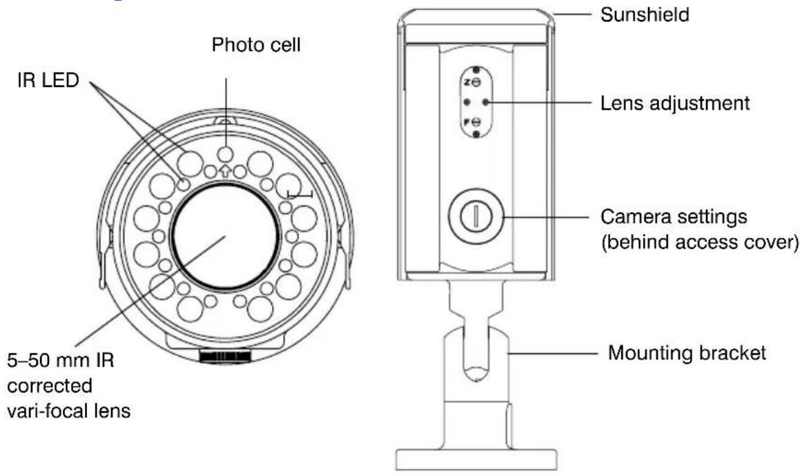
Figure 1 Camera Overview
Features
- High resolution 530 TVL 1/3" CCD provides a high-quality picture in low-light conditions
- 26 IR LEDs for illumination up to 125\~150 ft. (40\~47 m) depending on scene reflectivity, DSS on
- 5–50 mm F1.6 IR corrected Vari-focal lens with external controls for zoom and focus
- External access for camera On-screen Display (OSD) menu and day night threshold controls
• Digital Noise Reduction (DNR) minimizes video noise in low light - Digital Slow Shutter (DSS) for improved light sensitivity to extend the range of the light that the camera can detect in low-light conditions
• Automatic day/night switching with adjustable threshold level control
• 12 VDC or 24 VAC operation
Before You Begin
Unpack Everything
Check that the items received match those listed on the order form and packing slip. The HCD95534 packing box should include, in addition to this User Guide:
• One HCD95534 camera
- Four mounting screws
- One video test cable
- One allen wrench
- One adapter plate for 4S mounting box
If any parts are missing or damaged, contact the dealer you purchased the camera from or call Honeywell Customer Service (see the back of this manual).
Note A Phillips screwdriver and a flathead screwdriver may assist your installation.
Installation
The HCD95534 camera is designed for installation on a wall or ceiling. The HCD95534 is weather sealed for indoor or outdoor locations.
Attaching the Camera
- Position the camera to the desired mounting location on a wall or ceiling. Be sure the location is solid on a flat, smooth surface (for example, a crossbeam).
- Using the supplied mounting template, mark the four screw holes for installation.
- Using four screws appropriate to your installation, mount the camera at the marked holes.
The mounting bracket can be separated from the camera housing for easier installation. This is done by unscrewing and removing the thumb screw on the bracket. Replace and tighten the thumb screw after installation is complete.
Note To ensure a waterproof installation, the notch in the camera base that the power and video connections exit through should be facing down.
If the power and video connections exit the top of the base (wall mounted only), water may pool in the camera base. To minimize moisture entering the base, apply appropriate sealant around the notches and any other gaps between the camera base and the mounting surface.
Positioning the Camera
Caution Do not swivel and position the camera without the mounting bracket firmly in place.
Loosen the thumb screws and move the camera into position. Swivel the camera to capture the desired field of view. Tighten the thumb screws to set the position.
Lens Setup
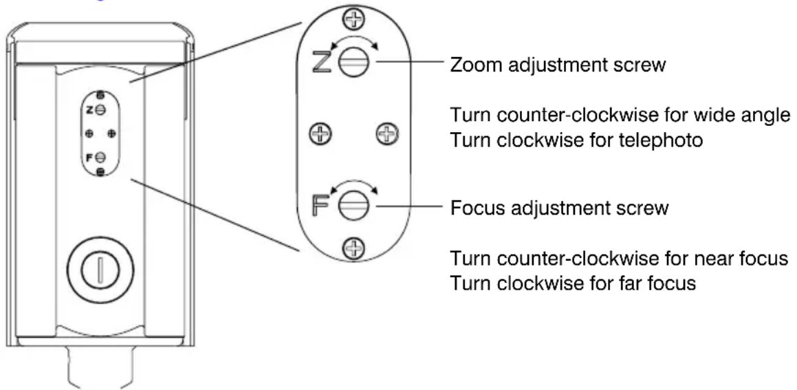
Adjusting the Zoom and Focus of the Lens
The zoom and focus adjustment is located on the underside front end of the camera housing. Use a flathead screwdriver to adjust the zoom and/or focus.
Figure 2 Lens Controller
Document 800-01802 Rev B 9 02/09
Camera Settings
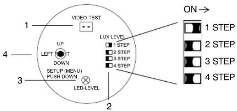
Camera Functions
Figure 3 Camera Controller
Legend
# Description
1 Video-test monitor output connector
2 LUX-level adjustment DIP switches. Only one switch should be on at a time. They modify the point at which the lux threshold (level of light) changes the mode of operation (color or B/W).
STEP Color to B/W (LED on) B/W to Color (LED off)
| 1 | 11–12 lux 12–13 lux |
| 2 | 8–9 lux 10–11 lux |
| 3 | 6–7 lux 7–8 lux |
| 4 | 1–3 lux 3–5 lux |
3 LED-level adjustment screw. Increase (turn clockwise) or lower (turn counter-clockwise) the IR LED brightness in night (B/W) mode.
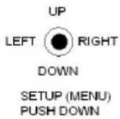
4 Camera OSD control (four position plus center push)
Legend
# Description
Press this control To do this ...
UP, DOWN Select a new item LEFT, RIGHT Select a menu item SETUP (MENU) Access a submenu
Connecting the Camera
- Connect the BNC video output connector to the video-in connector on your monitor or video recorder.
- Connect the camera to a power supply appropriate for your installation (12 VDC or 24 VAC).
Figure 4 Camera Connection
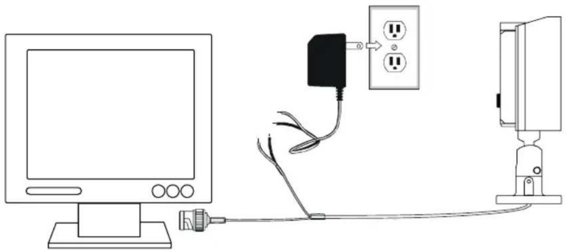
natural_image
Line drawing of a computer monitor connected to a power outlet and a wall-mounted device (no text or symbols)Setup Menu
The HCD95534 menu system consists of one main Setup menu (see Figure 5) for easy camera programming.
Press down on the SETUP (MENU) control (see Figure 3) to display the Setup menu.
Figure 5 Setup Menu
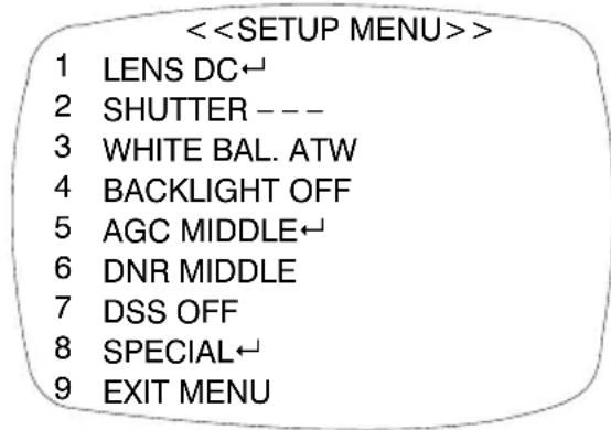
LENS — DC←, VIDEO, MANUAL
SHUTTER — FLK, ESC←, MANUAL
WHITE BAL. — ATW, MANUAL←, AWC←
BACKLIGHT — OFF, LOW, MIDDLE, HIGH
AGC — OFF, LOW←, MIDDLE←, HIGH←
DNR — OFF, LOW, MIDDLE, HIGH
DSS — OFF, AUTO←
SPECIAL←
EXIT MENU
← indicates submenus
SETUP Menu Functions
| Menu Item Option Description | ||
| 1 LENS DC | ↓ | Selects Lens type (the HCD95534 only supports DC mode at this time; choosing any other mode may cause incorrect/unpredictable camera operation). |
| VIDEO | ||
| MANUAL | ||
Menu Item Option Description
| 2 SHUTTER FLKESC↓MANUAL | Adjusts shutter settings.FLK = Flickerless mode reduces on-screen flickering. This is the only option available when the camera lens is set to DC mode (recommended).ESC = Electronic Shutter Control adjusts brightness level on screen.MANUAL = Allows you to adjust the shutter speed from 1/60-1/120,000 of a second (NTSC), or 1/50-1/120,000 (PAL). | |
| 3 WHITE BAL.(White Balance) | ATWMANUAL↓AWC↓ | Controls color on the screen.ATW = Select Auto Tracing White Balance when the color temp is 2400°K-12000°K (for example, under fluorescent light, or outdoors).MANUAL = Allows you to increase or decrease the red or blue factor on screen.AWC = Auto White Balance Control automatically adjusts the white balance to your specific environment. |
| 4 BACKLIGHT OFFLOWMIDDLEHIGH | Provides light level control to overcome severe backlighting conditions. | |
| 5 AGC(Automatic Gain Control) | OFFLOW↓MIDDLE↓HIGH↓ | Adjusts value of AGC gain.Increase the GAIN level to brighten the picture.Caution Noise or distortion may develop. |
| 6 DNR(Digital Noise Reduction) | OFFLOWMIDDLEHIGH | Reduces noise/distortion on the screen.Increasing the DNR level reduces noise but may introduce video artifacts. DNR is deactivated if AGC is turned off. |
Menu Item Option Description
| 7 DSS(Digital Slow Shutter) | OFF AUTO | Automatically provides a clear image under low-light conditions. You can control the maximum low-light magnification from 2x to 128x (increasing magnification may cause noise/distortion). DSS is deactivated when SHUTTER is set to FLK mode. |
| 8 SPECIAL -Opens the SPECIAL menu (see next section). | ||
| 9 EXIT Exits the SETUP menu and returns to video monitoring. | ||
SPECIAL Menu
- On the Setup menu, press the menu control UP or DOWN and then select SPECIAL.
- Press the SETUP (MENU) control to access the Special menu.
Figure 6 SPECIAL Menu
| <<SPECIAL MENU>> | ||
| 1 | CAMERA ID OFF | CAMERA ID —— OFF, ON← |
| 2 | COLOR AUTO | COLOR —— AUTO, ON |
| 3 | SYNC INT | SYNC —— INT (L/L) |
| 4 | MOTION DET OFF | MOTION DET —— OFF, ON← |
| 5 | PRIVACY OFF | PRIVACY —— OFF,ON← |
| 6 | MIRROR OFF | MIRROR —— OFF, ON |
| 7 | SHARPNESS ON← | SHARPNESS —— ON←, OFF |
| 8 | RESET | RESET |
| 9 | RETURN← | RETURN← |
← indicates submenus
SPECIAL Menu Functions
| Menu Item Option Description | ||
| 1 CAMERA ID | OFF ON | Sets a name to be displayed on the monitor.See Adding a Camera Title Display. |
| 2 COLOR AUTO ON | Sets the camera to either automatic color/black and white or full-time color mode. | |
| 3 SYNC INT | L/L | Synchronizes the vertical interval sync pulse of your camera with other equipment to reduce the effect of picture roll on the monitor.In Line Lock (L/L) mode you can adjust the phase from 0~359°. |
| 4 MOTION DET | OFF ON | Detects moving objects on screen, and displays MOTION DETECTED along with the number of movements counted.Allows you to select the area on screen you want to observe. See Setting Up Motion Detection. |
| 5 PRIVACY OFF ON | Allows you to mask certain areas of the screen from observation. | |
| 6 MIRROR OFF ON | Produces a horizontal mirror image on screen. | |
| 7 SHARP-NESS | ON OFF | Sharpens the image on screen. You can adjust the sharpness level from 0~31.Caution Excessive sharpening may cause picture noise. |
| 8 RESET Restores all factory default settings. | ||
| 9 RETURN -Returns to the main Setup menu. | ||
Adding a Camera Title Display
To add a camera title:
- On the Special menu, select CAMERA ID and then press SETUP (MENU).
Figure 7 Adding Camera Title
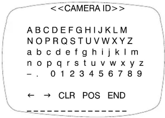
- Press the menu control UP, DOWN, LEFT, or RIGHT to select a character, then press SETUP (MENU) to accept it. The character is saved and the title cursor at the bottom of the screen moves to the next position. You can use the symbols to go back or forward in the title name to make changes, and you can also select CLR to delete the entire title and start again.
- Repeat step 2 until your camera title is complete.
- Select POS to position where you would like the camera title to be located on screen. Select the position using the menu control, then press (SETUP) MENU to confirm the position.
- Select END when you are finished.
Configuring Sync Control/Line-lock
Use this screen to synchronize the vertical interval sync pulse of your camera with other equipment to reduce the effect of picture roll on the monitor.
Note Line-lock mode is only available when using 24 VAC power.
Figure 8 Sync Control Setup
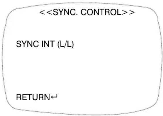
Menu Item Description
INTERNAL When line-lock is not required.
LINELOCK Adjusts the vertical phase (VPH):
VPH: 000\~359 (factory default is 0)
RETURN Press MENU to return to the Setup menu.
Setting Up Motion Detection
Use this screen to set up to four areas of the screen to detect moving objects. The screen displays MOTION DETECTED along with the number of movements counted.
Figure 9 Motion Detection Setup
<
AREA SEL AREA 1
AREA STATE ON
TOP |..|....| 10
DOWN |......|......| 25
LEFT |...|.....| 20
RIGHT |......|......| 40
Press SET to Return
| Menu Item | Option Description | |
| AREA SEL | AREA 1 | Selects which of the four motion detection grids top left, top right, bottom left, bottom right) you would like to modify. |
| AREA 2 | ||
| AREA 3 | ||
| AREA 4 | ||
| AREA STATE | ON | Activates or deactivates the selected grid. |
| OFF | ||
| TOP DOWN LEFT RIGHT | Press LEFT or RIGHT menu control to alter the dimensions of the selected grid. | |
Configuring Privacy Zones
Use this screen to set up to four areas of the screen for privacy mode; that is, the camera does not record video in these areas.
Figure 10 Privacy Mode Setup
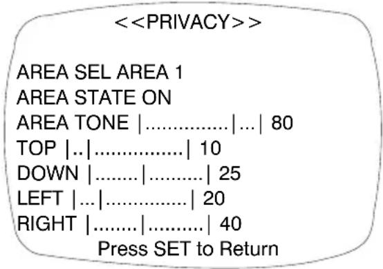
Menu Item Description
| AREA SEL AREA 1AREA 2AREA 3AREA 4 | Selects which of the four masking grids (top left, top right, bottom left, bottom right) you would like to modify. | |
| AREA STATE | ONOFF | Activates or deactivates the selected grid. |
| AREATONE | Changes the shade of the masking grids, by pressing the LEFT or RIGHT menu control. | |
| TOPDOWNLEFTRIGHT | Alters the dimensions of the selected grid by pressing the LEFT or RIGHT menu control. | |
Warranty and Service
Subject to the terms and conditions listed on the Product warranty, during the warranty period Honeywell will repair or replace, at its sole option, free of charge, any defective product returned prepaid.
In the event you have a problem with any Honeywell product, please call Customer Service at 1.800.796.CCTV (North America only) for assistance or to request a Return Merchandise Authorization (RMA) number. For Europe and the United Kingdom, please contact your Honeywell dealer. Be sure to have the model number, serial number, and the nature of the problem available for the technical service representative.
Prior authorization must be obtained for all returns, exchanges, or credits. Items shipped to Honeywell without a clearly identified Return Merchandise Authorization (RMA) number may be refused.
Specifications
HCD95534 (NTSC) HCD95534X (PAL)
| Operational | ||
| Image Sensor: 1/3” CCD | ||
| Video Standard: NTSC PAL | ||
| Scanning System: 525/60 lines 625/50 lines | ||
| Number of Pixels (H x V): | 768 x 494 | 752 x 582 |
| Minimum Illumination: 0 lux, operates in complete darkness | ||
| Horizontal Resolution: | Greater than 530 TVL | |
| Video Output: 1 Vp-p @ 75 Ohms | ||
| Sync System: 12 VDC: Internal 24 VAC: Internal/Line lock | ||
| S/N Ratio: 50 dB or more (AGC off) | ||
| Auto Gain Control: Off/On, selectable | ||
| ALC: Adjustable level control | ||
| Automatic Electronic Shutter: | 1/60–1/120,000 sec | 1/50–1/120,000 sec |
HCD95534 (NTSC)
HCD95534X (PAL)
Lens Type: 5-50 mm Vari-focal Auto Iris, IR corrected, F1.6
Horizontal Field of 51.3°–5.5°
View:
White Balance: ATW/AWC/Manual
BLC: Off/On, selectable
Gamma: 0.45
Line Lock Phase Adjustable Line lock vertical phase
Adjustment:
IR LEDs: 850 nm, 26 LEDs
IR Illumination 125 ft (40 m)–150 ft (47 m), depending on scene
Distance: reflectivity, DSS on
Digital Noise Off/Low/Middle/High
Reduction:
Digital Slow Shutter: x2-x128
Electrical
Input Voltage: 12 VDC/24 VAC
Input Range: 11–16 VDC, 17–28 VAC
Surge Suppression: 1.5 kW transient
Power Consumption: 15 W (max) with IR LEDs on
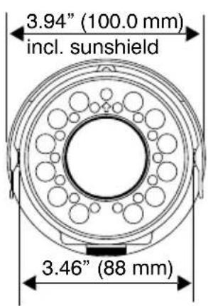
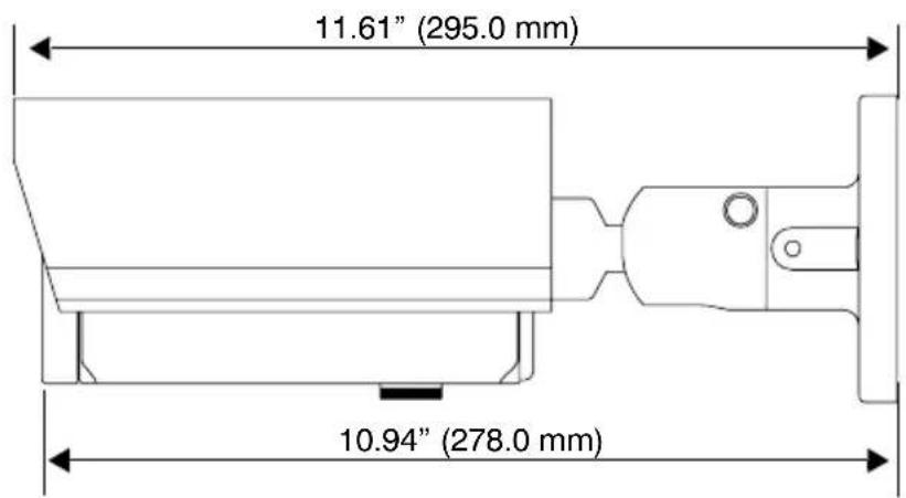
Mechanical
Dimensions: See diagram below
Weight: 2.8 lb (1.27 kg)
Construction: Housing: brushed and anodized aluminum with sunhood
Finish: brushed and anodized aluminum
Connector: Main Video Output: BNC connector
Aux Video Output: 2-pin connector for video test cable
Power Input: Tinned leads
Environmental
Temperature: Operating: -13°F to 122°F (-25°C to 50°C)
Storage: -35^ F to 140^ F ( -35^ C to 60^ C)
Relative Humidity: 0% to 85%, non-condensing
Rating: IP66
Regulatory
Emissions: FCC, CE (EN 55022)
Immunity: CE (EN 50130-4)
Safety: EU: 2006/95/EC LVD
Dimensions
Mounting Template
Figure 11 Mounting Template
Scale 1:1
Mounting screw holes (8/32 inch diameter)
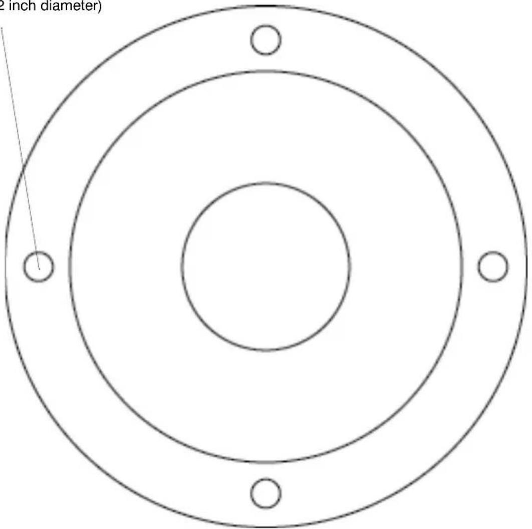
See “Attaching the Camera” on page 8 for information on using the mounting template.
Note The camera enclosure should be mounted on a flat, smooth surface.
Honeywell Systems Group (Head Office)
2700 Blankenbaker Pkwy, Suite 150
Louisville, KY 40299, USA
www.honeywellvideo.com
+1.800.796.2288
Honeywell Systems Group
Northern Europe
Ampérestraat 41
1446 TR Purmerend
The Netherlands
www.honeywell.com/security/nl
+31.299.410.200
Honeywell Systems Group Europe/South Africa
Aston Fields Road
Whitehouse Industrial Estate
Runcorn, Cheshire, WA7 3DL, UK
www.honeywell.com/security/uk
+44.01928.754028
D-72458 Albstadt, Germany
www.honeywell.com/security/de
+49.74 31.8 01.0
Honeywell Systems Group Pacific
Unit 5, Riverside Center
24-28 River Road West
Parramatta, NSW 2150, Australia
www.honeywellsecurity.com.au
+61.2.8837.9300
Honeywell Systems Group France
Immeuble Lavoisier
92160 Antony, France
www.honeywell.com/security/fr
+33.(0).1.40.96.20.50
Honeywell Systems Group Asia
35F Tower A, City Center
100 Zun Yi Road
Shanghai 200051, China
www.asia.security.honeywell.com
+86021.5257.4568
Honeywell Systems Group Italia SpA
www.honeywell.com/security/it
+39.02.4888.051
Honeywell Systems Group Middle East/N. Africa
Post Office Box 18530
LOB Building 08, Office 199
Jebel Ali, Dubai, United Arab Emirates
www.honeywell.com/security/me
+971.04.881.5506
Honeywell Systems Group España
www.honeywellvideo.com
+1.800.796.CCTV (North America only)
HVSsupport@honeywell.com
Document 800-01802 – Rev B – 02/09
© 2009 Honeywell International Inc. All rights reserved. No part of this publication may be reproduced by any means without written permission from Honeywell. The information in this publication is believed to be accurate in all respects. However, Honeywell cannot assume responsibility for any consequences resulting from the use thereof. The information contained herein is subject to change without notice. Revisions or new editions to this publication may be issued to incorporate such changes.
- HCD95534 True Day/Night IR Camera
- Revisions
- Issue Date Revisions
- Warnings
- Explanation of Graphical Symbols
- FCC Compliance Statement
- Caution
- Manufacturer's Declaration of Conformance
- Important Safety Information
- Precautions
- Contents
- Introduction 6
- Installation....8
- Lens Setup 9
- Camera Settings....9
- Programming 11
- Warranty and Service....19
- Specifications....20
- Mounting Template 23
- Introduction
- Features
- Before You Begin
- Unpack Everything
- Installation
- Attaching the Camera
- Positioning the Camera
- Lens Setup
- Adjusting the Zoom and Focus of the Lens
- Camera Settings
- Camera Functions
- Legend
- # Description
- Press this control To do this ...
- Connecting the Camera
- Setup Menu
- SPECIAL Menu
- Adding a Camera Title Display
- Configuring Sync Control/Line-lock
- Menu Item Description
- Setting Up Motion Detection
- Configuring Privacy Zones
- Warranty and Service
- Specifications
- HCD95534 (NTSC)
- HCD95534X (PAL)
- Electrical
- Mechanical
- Environmental
- Regulatory
- Dimensions
- Mounting Template
- Honeywell Systems Group (Head Office)
- Honeywell Systems Group
- Honeywell Systems Group Europe/South Africa
- Honeywell Systems Group Pacific
- Honeywell Systems Group France
- Honeywell Systems Group Asia
- Honeywell Systems Group Italia SpA
- Honeywell Systems Group Middle East/N. Africa
- Honeywell Systems Group España
Brand : HONEYWELL
Model : HCD95534
Category : Security Camera