EPA6220 - Security Camera EverFocus - Free user manual and instructions
Find the device manual for free EPA6220 EverFocus in PDF.


| Product Type | AHD 1080p IR Speed Dome Security Camera |
| Model | EPA6220 |
| Image Sensor | Sony CMOS, 1920 x 1080 pixels |
| Lens | 20x optical zoom, 4.7 - 94 mm |
| Video Output | AHD / TVI / CVI / CVBS switchable, 1Vp-p 75Ω |
| Day/Night | True Day/Night with IR-cut filter (auto/manual) |
| Minimum Illumination | Color: 0.01 Lux; B/W: 0.001 Lux |
| IR LEDs | 8 units, range up to 150 m (492 ft) |
| Pan/Tilt Range | Pan: 0° - 360°; Tilt: 0° - 93° |
| Pan/Tilt Speed | Pan: up to 480°/s; Tilt: up to 240°/s |
| Preset Points | 220 |
| Tours | 8 tours, up to 16 presets each |
| Patterns | 4 patterns (max. 15 min each) |
| Communication | RS-485 (Pelco-D/P) and coaxial UTC |
| Power Supply | 12 VDC / 4 A or 24 VAC~ / 3 A (dual) |
| Power Consumption | ≤ 25 W |
| Weather Resistance | IP66 |
| Operating Temperature | -40°C to 60°C (-40°F to 140°F) |
| Dimensions (Package) | 310 x 310 x 440 mm (12.2 x 12.2 x 17.3 in) |
| Weight | 6.1 kg (13.45 lb) with 12 VDC; 7.15 kg (15.76 lb) with 24 VAC |
| Mounting | Wall, corner, pole, ceiling (optional brackets) |
| Cleaning | Use lens tissue or cotton swab with ethanol for lens; damp cloth for body; avoid solvents |
| Safety | Keep away from water, oil, gas; use proper mounting and fused/Class 2 power supply |
| Certifications | CE, FCC Part 15 Class A |
Frequently Asked Questions - EPA6220 EverFocus
User questions about EPA6220 EverFocus
0 question about this device. Answer the ones you know or ask your own.
Ask a new question about this device
Download the instructions for your Security Camera in PDF format for free! Find your manual EPA6220 - EverFocus and take your electronic device back in hand. On this page are published all the documents necessary for the use of your device. EPA6220 by EverFocus.
USER MANUAL EPA6220 EverFocus
AHD 1080p IR / IP66 Outdoor Speed Dome
True Day/Night and WDR (20x / 36x Optical Zoom)
eZ.HD
User's Manual
natural_image
Exterior view of a white surveillance camera with 'EverFocus' branding (no additional text or symbols visible)EverFocus
Copyright © EverFocus Electronics Corp.
Release Date: February, 2019
EverFocus
Copyright © 1995 - 2019 EverFocus Electronics Corp.
Disclaimer
All the images including product pictures or screen shots in this document are for example only. The images may vary depending on the product and software version. Information contained in this document is subject to change without notice.
Copyright
All rights reserved. No part of the contents of this manual may be reproduced or transmitted in any form or by any means without written permission of the EverFocus Electronics Corporation.
EverFocus
2F., No.12, Ln. 270, Sec. 3, Beishen Rd.,
Shenkeng Dist., New Taipei City 222, Taiwan
TEL: +886 2 2662 2338
FAX: +886 2 2662 3632
www.everfocus.com.tw
February, 2019
About this document
All the safety and operating instructions should be read and followed before the unit is operated. This manual should be retained for future reference. The information in this manual was current when published. The manufacturer reserves the right to revise and improve its products. All specifications are therefore subject to change without notice.
Regulatory Notices
FCC Notice "Declaration of Conformity Information"
This equipment has been tested and found to comply with the limits for a Class A digital device, pursuant to part 15 of the FCC Rules. These limits are designed to provide reasonable protection against harmful interference in a residential installation. This equipment generates, uses and can radiate radio frequency energy and, if not installed and used in accordance with the instructions, may cause harmful interference to radio communications. However, there is no guarantee that interference will not occur in a particular installation. If this equipment does cause harmful interference to radio or television reception, which can be determined by turning the equipment off and on, the user is encouraged to try to correct the interference by one or more of the following measures:
- Reorient or relocate the receiving antenna.
- Increase the separation between the equipment and receiver.
- Connect the equipment into an outlet on a circuit different from that to which the receiver is connected.
- Consult the dealer or an experienced radio/TV technician for help.
Warning: Changes or modifications made to this equipment, not expressly approved by EverFocus or parties authorized by EverFocus could void the user's authority to operate the equipment.
This device complies with part 15 of the FCC Rules. Operation is subject to the following two conditions:
(1) This device may not cause harmful interference, and
(2) This device must accept any interference received, including interference that may cause undesired operation.
EPTZ cameras comply with CE and FCC.
Precautions
- Do not install the camera near electric or magnetic fields.
Install the camera away from TV/radio transmitters, magnets, electric motors, transformers and audio speakers since the electromagnetic fields generated from these devices may distort the video image or otherwise interfere with camera operation.
- Never disassemble the camera beyond the recommendations in this manual nor introduce materials other than those recommended herein.
Improper disassembly or introduction of corrosive materials may result in equipment failure or other damage.
- Try to avoid facing the camera toward the sun.
In some circumstances, direct sunlight may cause permanent damage to the sensor and/or internal circuits, as well as creating unbalanced illumination beyond the capability of the camera to compensate.
- Keep the power cord away from water and other liquids and never touch the power cord with wet hands.
Touching a wet power cord with your hands or touching the power cord with wet hands may result in electric shock.
- Never install the camera in areas exposed to oil, gas or solvents.
Oil, gas or solvents may result in equipment failure, electric shock or, in extreme cases, fire.
- Cleaning
For cameras with interchangeable lenses, do not touch the surface of the sensor directly with the hands. Use lens tissue or a cotton tipped applicator and ethanol to clean the sensor and the camera lens. Use a damp soft cloth to remove any dirt from the camera body. Please do not use complex solvents, corrosive or abrasive agents for cleaning of any part of the camera.
- Do not operate the camera beyond the specified temperature, humidity or power source ratings.
Use the outdoor camera at temperatures within -40^ +60^ ≤ 95% / -40^ +140^ ≤ 95% ; this device is not rated as submersible. The input power source is 12VDC or 24VAC\~. Be sure to connect the proper + / - polarity and voltage, as incorrect polarity or too high a voltage will likely cause the camera to fail, and such damage is not covered by the warranty. The use of properly fused or Class 2 power limited type supplies is highly recommended.
- Mounting
Use care in selecting a solid mounting surface which will support the weight of the camera plus any wind, snow, ice or other loading, and securely attach the camera to the mounting surface using screws and anchors which will properly support the camera. If necessary (e.g. when mounting to drop ceilings) use a safety wire to provide additional support for the camera.
CONTENTS
1. Introduction....1
1.1 Features....1
1.2 Dimensions....1
1.3 Packing List....2
1.4 Optional Accessories....2
2. Installation....3
2.1 Wall Mounting....3
2.2 Corner Mounting....4
2.3 Pole Mounting....5
2.4 Ceiling Mounting....6
2.5 Cable Connection ....7
2.5.1 Coaxial and RS-485 Cables....7
2.5.2 Power Cable 7
3. OSD Menu Tree....8
4. OSD Menu 10
4.1 System....10
4.2 Dome 11
4.2.1 COMM....11
4.2.2 IR DISPLAY....11
4.2.3 GUARD TOUR....12
4.2.4 A-B SCAN....13
4.2.5 PAN SCAN....13
4.2.6 PATTERN 14
4.2.7 PARK ACTION 14
4.2.8 PRIVACY ZONE....15
4.2.9 ADVANCED....15
4.3 Camera 16
4.4 Display....16
4.5 Language 17
4.6 Timing Task....17
4.6.1 TIME SETTING....17
4.6.2 TIME TASK....17
4.7 Alarm....18
4.8 Reset....18
5. Specifications 19
Appendix....21
A.Shortcut Commands....21
B.Troubleshooting....22
1. Introduction
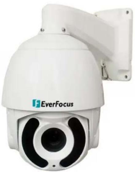
The EPA6220 / EPA6236 1080p speed dome cameras come with 20x / 36x optical zoom lens respectively. Equipped with a weather-resistant (IP66) housing, the models meet a wide variety of needs for outdoor surveillance. The speed dome cameras support AHD, TVI, CVI and CVBS video formats, which are switchable via shortcut commends (please refer to Appendix A Shortcut Commands).
EPA6220 / EPA6236 provides variable pan / tilt speeds for fast and accurate monitoring. A maximum of 220 preset points can be configured for precise location of target areas. Features like A-B scan, 4 patterns, 8 tours are all provided. The speed dome cameras also feature IR-Cut Filter, which can be removed or attached manually or automatically switched based on the detected light levels. A built-in fan and heater are also equipped in the speed dome camera.
1.1 Features
• AHD 1080p Sony CMOS sensor
• Supports UTC & RS-485 communication
• True Day and Night (IR-cut filter removable)
• Supports D-WDR
• Supports 220 preset positions
• Supports 8 tours (16 positions each tour)
• IP66-rated with metal housing
• Supports OSD menu
• 20x optical zoom lens (for EPA6220) / 36x optical zoom lens (for EPA6236)
1.2 Dimensions
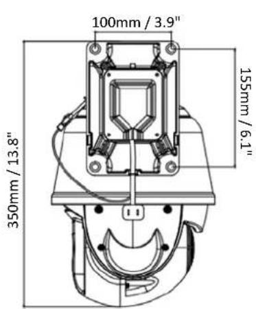
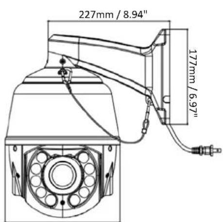
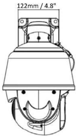
1.3 Packing List
- Speed Dome Camera x 1
- Wall Mount Bracket x 1
- Power Supply (12VDC, 4A) x 1
- Screw Kit x 1
- Quick Installation Guide x 1
Note:
- Equipment configurations and supplied accessories vary by country. Please consult your local EverFocus office or agents for more information. Please also keep the shipping carton for possible future use.
- Contact the shipper if any items appear to have been damaged in the shipping process.
1.4 Optional Accessories
- Pole Mount Bracket
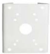
• Corner Mount Bracket
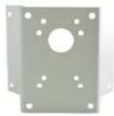
- Pendant Mount Bracket
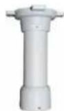
• EKB700 Keyboard (RS-485)
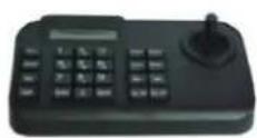
2. Installation
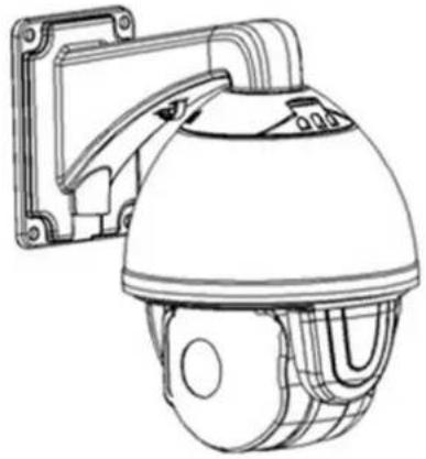
2.1 Wall Mounting
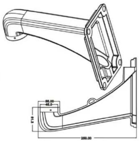
You can use the supplied Wall Mount Bracket to install the speed dome camera to the concrete wall. Note that the wall should be withstood at least 4 times the weight of the speed dome camera.
Wall Mount Bracket
natural_image
Line drawing of a security camera with mounted frame and dome (no text or symbols)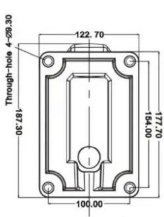
- Mark the 4 screw holes on the wall based on the Wall Mount Bracket and then drill 4 screw-depth holes on the wall.
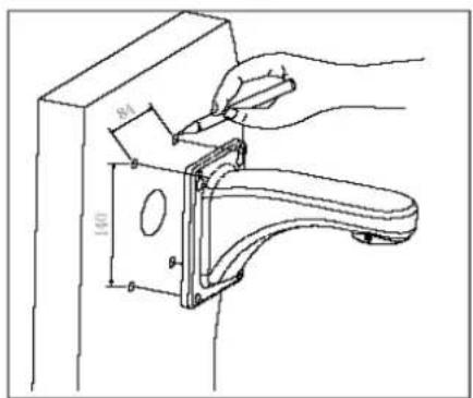
- Run the cables through the Wall Mount Bracket and then screw the Wall Mount Bracket to the wall with M8 screws.
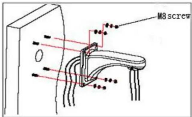
- Screw the speed dome camera to the Wall Mount Bracket.
2.2 Corner Mounting
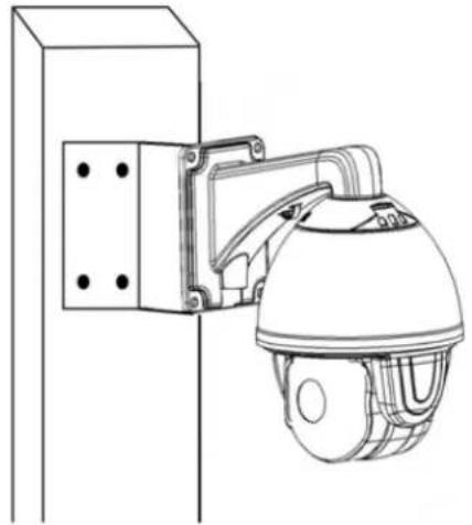
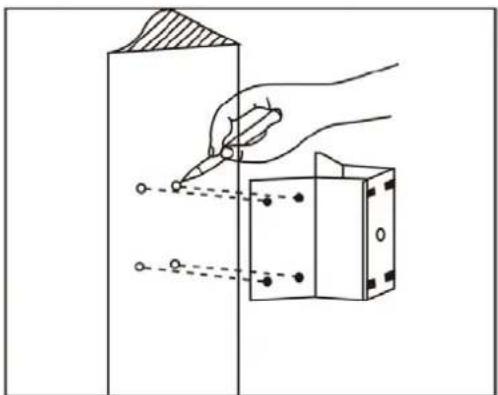
You can purchase the Corner Mount Bracket (please refer to 1.4 Optional Accessories) to install the speed dome camera to the concrete corner wall with 90° angle. Note that the wall should be withstood at least 4 times the weight of the speed dome camera.
Corner Mount Bracket
natural_image
Line drawing of a security camera mounted on a vertical panel (no text or symbols)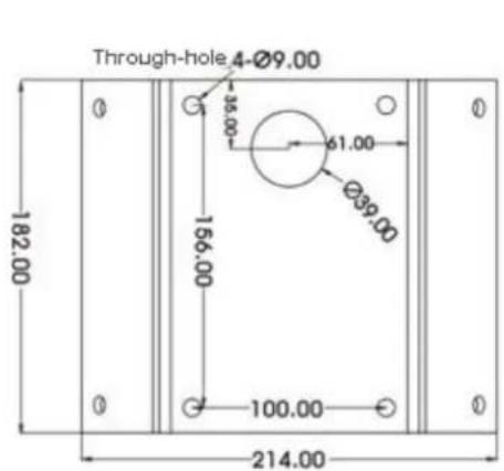
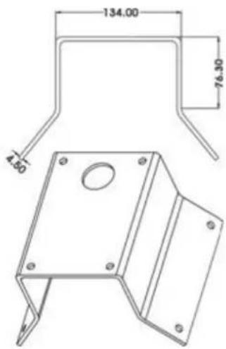
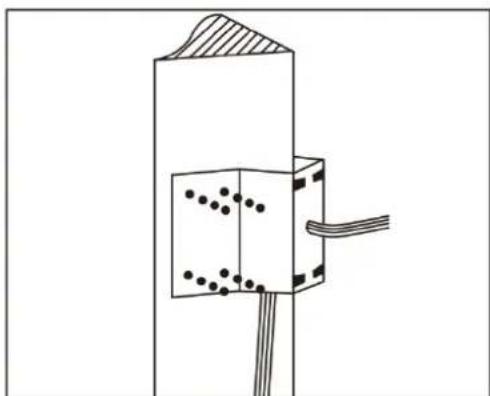
- Mark the screw holes on the wall based on the Corner Mount Bracket, drill the screw-depth holes and then screw the Corner Mount Bracket to the wall with M8 screws and screw nuts.
natural_image
Diagram showing a hand using a tool to mark points on a vertical surface next to a rectangular block (no text or symbols present)- Run the cables through the Wall Mount Bracket and Corner Mount Bracket, and then screw the Wall Mount Bracket to the Corner Mount Bracket.
natural_image
Pure technical diagram of a mechanical or electrical component with no visible text, numbers, or symbols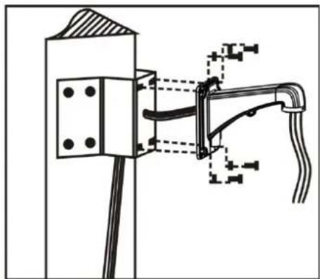
natural_image
Technical diagram of a mechanical assembly with no visible text or symbols- Screw the speed dome camera to the Wall Mount Bracket.
2.3 Pole Mounting
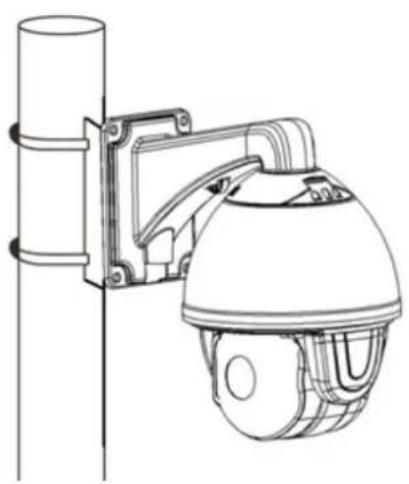
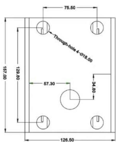
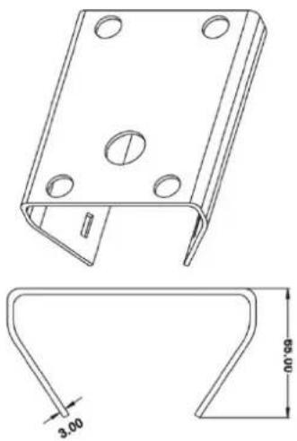
You can purchase the Pole Mount Bracket (please refer to 1.4 Optional Accessories) to install the speed dome camera to a pole structure with diameter between 130-152mm (max. 6 inches). Note that the pole structure should be withstood at least 4 times the weight of the speed dome camera.
natural_image
Line drawing of a security camera mounted on a vertical pole, showing no text or symbols.Pole Mount Bracket
natural_image
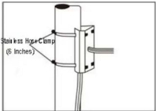
Technical drawing of a metal bracket with mounting holes and a side profile detail (no text or symbols)- Fix the Pole Mount Bracket to the pole structure using the Stainless Hose Clamps ( 130-152mm).
- Run the cables through the Wall Mount Bracket and Pole Mount Bracket, and then screw the Wall Mount Bracket to the Pole Mount Bracket.
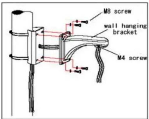
- Screw the speed dome camera to the Wall Mount Bracket.
2.4 Ceiling Mounting
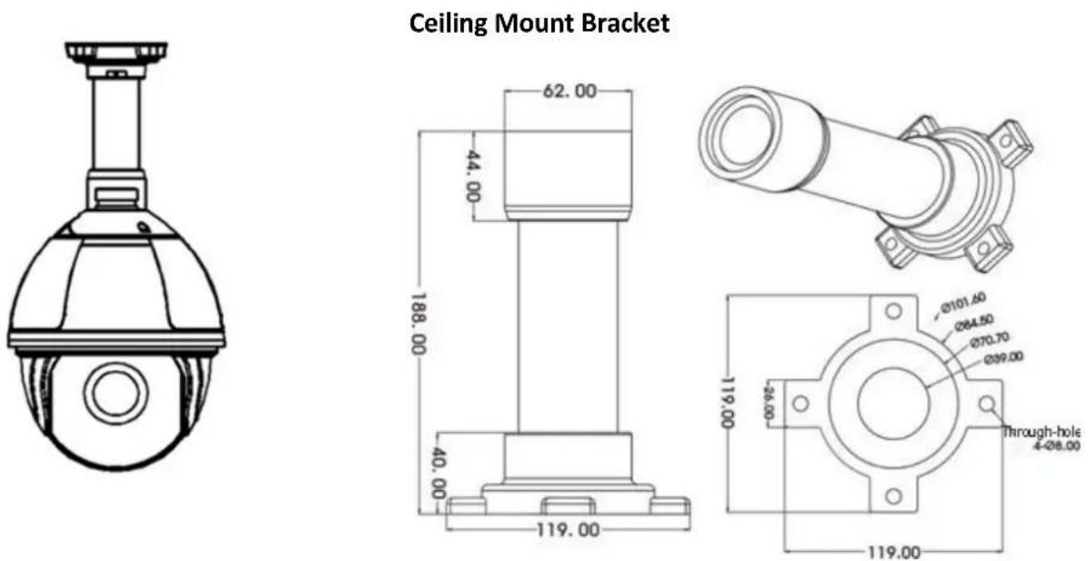
You can purchase the Ceiling Mount Bracket (please refer to 1.4 Optional Accessories) to install the speed dome camera to the ceiling. Note that the ceiling should be withstood at least 4 times the weight of the speed dome camera.
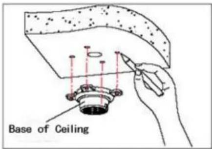
- Unscrew the M4 screws to remove the Bracket Base from the Ceiling Mount Bracket. Mark the screw holes on the ceiling based on the Bracket Base, drill the screw-depth holes and then screw the Bracket Base to the ceiling with M6 screws. You can optionally apply the silica gel to the faying surface between the Bracket Base and ceiling for water proofing.
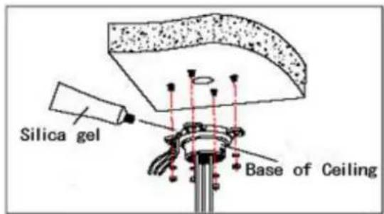
- Run the cables through the Ceiling Mount Bracket, and then screw the Ceiling Mount Bracket to the Bracket Base. You can optionally apply the silica gel to the joint sleeve for water proofing.
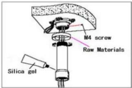
- Screw the speed dome camera to the Ceiling Mount Bracket.
2.5 Cable Connection
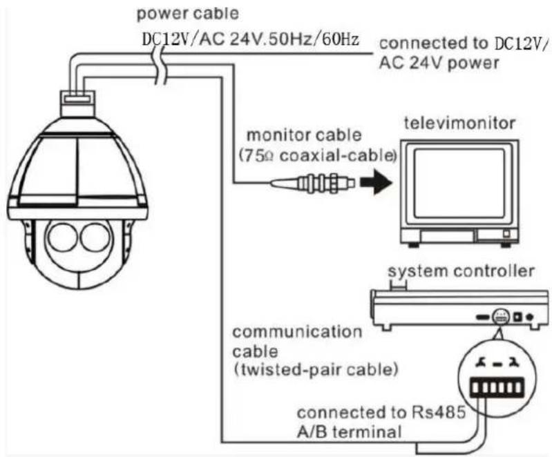
flowchart
graph TD
    A["Power Cable"] -->|DC12V/AC 24V.50Hz/60Hz| B["monitor Cable (75Ω coaxial-cable)"]
    B --> C["Television Monitor"]
    C --> D["System Controller"]
    D --> E["Connected to Rs485 A/B terminal"]
    E --> F["communication Cable (twisted-pair cable)"]
    F --> G["Power Cable"]
    style A fill:#f9f,stroke:#333
    style B fill:#ccf,stroke:#333
    style C fill:#cfc,stroke:#333
    style D fill:#fcc,stroke:#333
    style E fill:#cff,stroke:#333
2.5.1 Coaxial and RS-485 Cables
The speed dome cameras support UTC function and RS-485 communication. You can control the speed dome cameras either through UTC (over coaxial cable) or RS-485 (RS-485 wires).
2.5.2 Power Cable
The speed dome cameras support dual power, 12VDC/4A and 24VAC\~/3A.
In general, the power cable has resistance, there are internal losses when transmitting the voltage, the longer of the cable used, the smaller the wire diameter, the worse loss will suffer. In order to avoid losses of cable causing low voltage and keep the dome work properly, when processing wiring please refer to the requirement below:
| Cable Diameter | 0.5mm ^2 (20#) | 1.0mm ^2 (18#) | 1.5mm ^2 (16#) | 2.5mm ^2 (14#) |
| Dome Distance | 11m(37ft) | 18m(60ft) | 29m(95ft) | 46m(152ft) |
For example, if a dome is 35 meters away from the power supply, power cable used must be more than 2.5mm^2 , otherwise, the dome may suffer insufficient power supply and could not work properly.
Remark: The dome with 12VDC should be less than 3 meters away from power supply.
- OSD Menu Tree
| No. | Main Menu | 1^st Layer | 2^nd Layer | 3^rd Layer |
| 1 System | MFG | |||
| Protocol | ||||
| Dome ID | ||||
| Comm | ||||
| Temperature | ||||
| Version | ||||
| Exit | ||||
| 2 Dome | Comm | Device ID | ||
| Check ID | ||||
| Target ID | 1-250 | |||
| Soft Protocol | Auto | |||
| Baud Rate | 1200, 2400, 4800, 9600 | |||
| Comm Reset | ||||
| Save | ||||
| Exit | ||||
| IR Display | Working Mode | Auto, Off, On | ||
| Testing Time | 2-15 sec. | |||
| Output Power | 40%, 60%, 80%, 100% | |||
| Illumination On | 1-15 | |||
| Ambient Light | 0-50 | |||
| IR Switch Zoom | 1-10 | |||
| Exit | ||||
| Guard Tours | Guard Tour | 1-8 | ||
| Setting | ID (1-16), Point, Time, Speed | |||
| Init | ||||
| Running | ||||
| Delete | ||||
| Exit | ||||
| A-B Scan | Preset A | 0-64 | ||
| Preset B | 0-64 | |||
| Scan Speed | 1-64 | |||
| Dwell Time | 2-60 sec. | |||
| Running | ||||
| Delete | ||||
| Exit | ||||
| PAN Scan | PAN Scan Speed | 1-64 | ||
| Init | ||||
| Running | ||||
| Exit | ||||
| Pattern | Pattern No | 1-4 | ||
| Setting | ||||
| Running | ||||
| Delete | ||||
| Exit | ||||
| Park Action | Park Mode | Off, AB Scan, 360, Home, Tour1, Pattern1 | ||
| Park Time | 1-60 min. | |||
| Setting | ||||
| Call | ||||
| Delete | ||||
| Exit | ||||
| Privacy Zone | N/A | |||
| Advanced | PWR On Act | Action (memory), Off, AB Scan, 360, Home, Tour1, Pattern1 | ||
| Ratio Speed | On, Off | |||
| Auto Flip | On, Off | |||
| Others | N/A | |||
| Exit | ||||
| 3 | Camera | Cam | Auto, CNB, LG, Samsung, Hitachi, Yoko, XF, WX, Sony | |
| Zoom Speed | Quick, Slow | |||
| Digital Zoom | On, Off | |||
| Focus | Auto, Manual | |||
| Iris | Auto, Manual | |||
| BLC | On, Off | |||
| Freeze | On, Off | |||
| Exit | ||||
| 4 | Display | P and T | On, Off | |
| Zoom | On, Off | |||
| Action | On, Off | |||
| Dome ID | On, Off | |||
| Comm | On, Off | |||
| Time | On, Off | |||
| Exit | ||||
| 5 | Language | Language | English, Spanish, French, Portuguese, Polish, German, Italian | |
| Exit | ||||
| 6 | Timing Task | Time Setting | Time-Year | |
| Time-Month | ||||
| Time-Date | ||||
| Time-Hour | ||||
| Time-Min | ||||
| Time-Sec | ||||
| Save | ||||
| Exit | ||||
| Timing Task | Off, AB Scan, 360, Tour1, Tour2, Tour3, Tour4, Pattern1, Pattern2, | |||
| Exit | ||||
| 7 | Alarm | Alarm | On, Off | |
| Patrol Time | 2-60 sec. | |||
| Alarm Linkage | On, Off | |||
| Alarm 1 | 1-64 | |||
| Alarm 2 | 1-64 | |||
| Alarm 3 | 1-64 | |||
| Alarm 4 | 1-64 | |||
| Release Time | Off, 2-60 sec. | |||
| Exit | ||||
| 8 | Reset | Dome Restart | ||
| Sys Data | ||||
| Cam Data | ||||
| Preset | ||||
| Exit | ||||
| 9 | Exit | |||
4. OSD Menu
| MAIN MENU |
4.1 System
| MAIN MENU | SYSTEM |
| < SYSTEM > | MFG |
| < DOME > | PROTOCOL AUTO |
| < CAMERA > | DOME ID 001 |
| < DISPLAY > | COMM 9600-N-8-1 |
| < LANGUAGE > | TEMPERATURE 33 |
| < TIMING TASK > | VERSION A123456 |
| < ALARM > | EXIT |
| < RESET > | |
| EXIT |
MFG: Max 15 characters displayed on the screen.
PROTOCOL: Displays the protocol of the dome. To configure the value, go to DOME > COMM.
DOME ID: Displays the dome address. To configure the value, go to DOME > COMM.
COMM: Displays the baud rate, check bit, data bit, start bit. To configure the value, go to DOME > COMM.
TEMPERATURE: Displays the temperature of the dome.
VERSION: Displays the version of the dome.
EXIT: Exit the current menu.
4.2 Dome
4.2.1 COMM
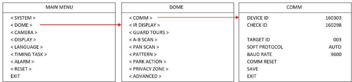
flowchart
graph LR
    A["MAIN MENU"] --> B["DOME"]
    B --> C["COMM"]

    A1["< SYSTEM >"] --> A2["< COMM >"]
    A3["< DOME >"] --> A4["< IR DISPLAY >"]
    A5["< CAMERA >"] --> A6["< GUARD TOURS >"]
    A7["< DISPLAY >"] --> A8["< A-B SCAN >"]
    A9["< LANGUAGE >"] --> A10["< PAN SCAN >"]
    A11["< TIMING TASK >"] --> A12["< PATTERN >"]
    A13["< ALARM >"] --> A14["< PARK ACTION >"]
    A15["< RESET >"] --> A16["< PRIVACY ZONE >"]
    A17["EXIT"] --> A18["< ADVANCED >"]

    B1["< COMM >"] --> B2["DEVICE ID 160303"]
    B3["< IR DISPLAY >"] --> B4["CHECK ID 160298"]
    B5["< GUARD TOURS >"] --> B6["TARGET ID 003"]
    B7["< A-B SCAN >"] --> B8["SOFT PROTOCOL AUTO"]
    B9["< PATTERN >"] --> B10["BAUD RATE 9600"]
    B11["< PARK ACTION >"] --> B12["COMM RESET"]
    B13["< PRIVACY ZONE >"] --> B14["SAVE"]
    B15["< ADVANCED >"] --> B16["EXIT"]
DEVICE ID: The device ID is auto generated by the system.
CHECK ID: To change the TARGET ID, please input the CHECK ID exactly same as the DEVICE ID displays on the screen.
TARGET ID: Target ID is available from 001 to 250, which can be used to distinguish several domes with the same ID.
SOFT PROTOCOL: Select a protocol for the dome.
BAUD RATE: Select a baud rate for the dome. Options include 1200BPS, 2400BPS, 4800BPS and 9600BPS.
COMM RESET: Enter to restore the COMM settings to factory default and then automatically restart the dome.
SAVE: Enter to save all the configurations. The dome will reboot.
EXIT: Exit the current menu.
4.2.2 IR DISPLAY
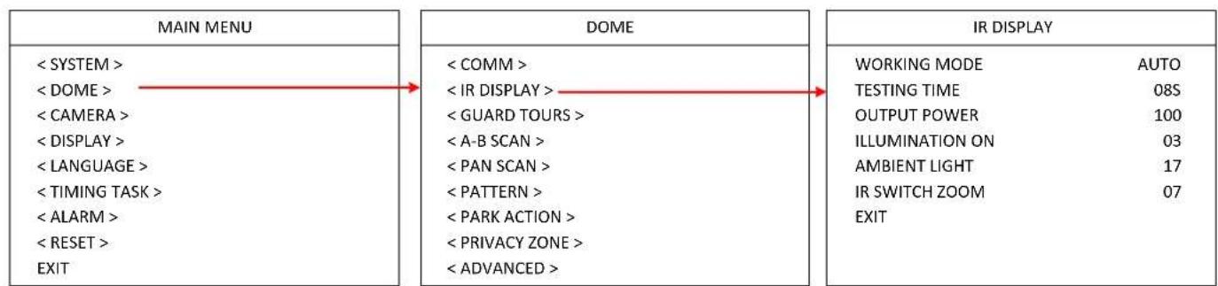
flowchart
graph LR
    A["MAIN MENU"] --> B["DOME"]
    B --> C["IR DISPLAY"]
    A --> A1["< SYSTEM >"]
    A --> A2["< DOME >"]
    A --> A3["< CAMERA >"]
    A --> A4["< DISPLAY >"]
    A --> A5["< LANGUAGE >"]
    A --> A6["< TIMING TASK >"]
    A --> A7["< ALARM >"]
    A --> A8["< RESET >"]
    A --> A9["EXIT"]
    B --> B1["< COMM >"]
    B --> B2["< IR DISPLAY >"]
    B --> B3["< GUARD TOURS >"]
    B --> B4["< A-B SCAN >"]
    B --> B5["< PAN SCAN >"]
    B --> B6["< PATTERN >"]
    B --> B7["< PARK ACTION >"]
    B --> B8["< PRIVACY ZONE >"]
    B --> B9["< ADVANCED >"]
    C --> C1["WORKING MODE AUTO"]
    C --> C2["TESTING TIME 08S"]
    C --> C3["OUTPUT POWER 100"]
    C --> C4["ILLUMINATION ON 03"]
    C --> C5["AMBIENT LIGHT 17"]
    C --> C6["IR SWITCH ZOOM 07"]
    C --> C7["EXIT"]
WORKING MODE: Select an IR working mode for Day/Night switch. Options include Auto, Off (black & white) and On (color). If Auto is selected, the dome will automatically switch from day to night mode when the illumination level is low; or automatically switch from night to day mode when the illumination level is high.
TESTING TIME: If Auto is selected from the IR working mode, you can set up a switch time (switch from day to night or night to day) to activate the switch action.
OUTPUT POWER: Select an output power. Options include 40%, 60%, 80% and 100%.
ILLUMINATION ON: Illumination on is 1 to 15 grade selectable and default is 3. If Auto IR working mode is selected, when the Illumination On level is lower than the ambient light, the picture will change to color, the IR illumination will turn off automatically. When the Illumination On level is higher than the ambient light, the picture will change to black and white, the IR illumination will turn on automatically.
AMBIENT LIGHT: Ambient light is a system data. User cannot change it manually. The Ambient Light changes according to the environment all the time. The data will refresh every time when user enter the OSD.
IR SWITCH ZOOM: When zoom value reaches the demanded setting, the IR LEDs with auto switch from near illumination to far illumination.
EXIT: Exit the current menu.
4.2.3 GUARD TOUR
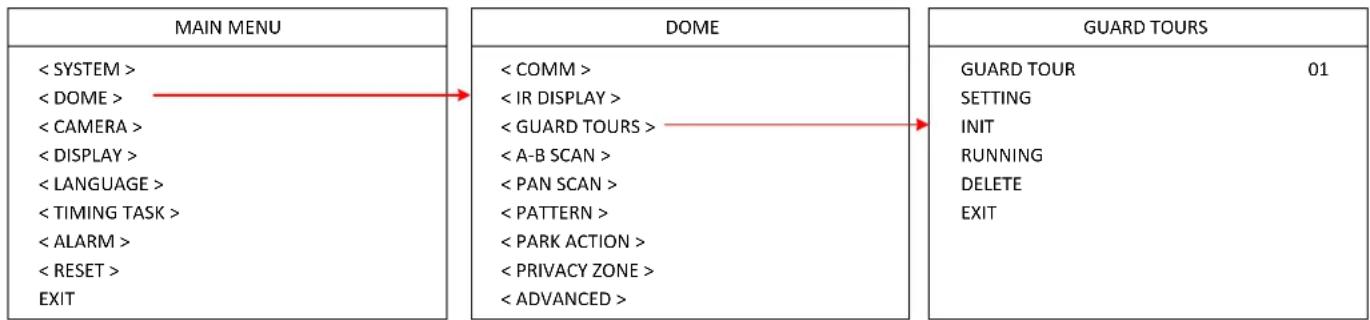
flowchart
graph LR
    A["MAIN MENU"] --> B["DOME"]
    B --> C["GUARD TOURS"]

    A1["< SYSTEM >"] --> A2["< COMM >"]
    A3["< DOME >"] --> A4["< IR DISPLAY >"]
    A5["< CAMERA >"] --> A6["< GUARD TOURS >"]
    A7["< DISPLAY >"] --> A8["< A-B SCAN >"]
    A9["< LANGUAGE >"] --> A10["< PAN SCAN >"]
    A11["< TIMING TASK >"] --> A12["< PATTERN >"]
    A13["< ALARM >"] --> A14["< PARK ACTION >"]
    A15["< RESET >"] --> A16["< PRIVACY ZONE >"]
    A17["EXIT"] --> A18["< ADVANCED >"]

    B1["< COMM >"] --> B2["< IR DISPLAY >"]
    B3["< GUARD TOURS >"] --> B4["< A-B SCAN >"]
    B5["< PATTERN >"] --> B6["< PARK ACTION >"]
    B7["< PRIVACY ZONE >"] --> B8["< ADVANCED >"]

    C1["GUARD TOUR 01"] --> C2["SETTING"]
    C3["INIT"] --> C4["RUNNING"]
    C5["DELETE"] --> C6["EXIT"]
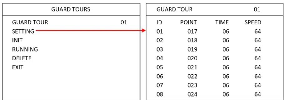
GUARD TOUR: Select a number to start setting the Tour function. Up to 8 tours can be set up.
SETTING: You can set-up up to 16 presets to each guard tour. Preset point is from 0-64 (0 is invalid). Dwell time is from 1 to 60s. Speed value is from 1 to 64.
other
| GUARD TOURS | 01 | |---|---| | ID | POINT TIME SPEED | | 01 | 017 06 64 | | 02 | 018 06 64 | | 03 | 019 06 64 | | 04 | 020 06 64 | | 05 | 021 06 64 | | 06 | 022 06 64 | | 07 | 023 06 64 | | 08 | 024 06 64 |INIT: Enter to initialize the preset point, dwell time and speed to default value.
RUNNING: Enter to activate this tour function.
DELETE: Enter to delete the setting of this tour. The preset points will display as 0.
EXIT: Exit the current menu.
4.2.4 A-B SCAN
flowchart
graph LR
    A["MAIN MENU"] --> B["DOME"]
    B --> C["A-B SCAN"]

    A1["< SYSTEM >"] --> A2["< COMM >"]
    A2 --> A3["< IR DISPLAY >"]
    A3 --> A4["< GUARD TOURS >"]
    A4 --> A5["< A-B SCAN >"]
    A5 --> A6["< PAN SCAN >"]
    A6 --> A7["< PATTERN >"]
    A7 --> A8["< PARK ACTION >"]
    A8 --> A9["< PRIVACY ZONE >"]
    A9 --> A10["< ADVANCED >"]

    B1["< COMM >"] --> B2["< IR DISPLAY >"]
    B2 --> B3["< GUARD TOURS >"]
    B3 --> B4["< A-B SCAN >"]
    B4 --> B5["< PAN SCAN >"]
    B5 --> B6["< PATTERN >"]
    B6 --> B7["< PARK ACTION >"]
    B7 --> B8["< PRIVACY ZONE >"]
    B8 --> B9["< ADVANCED >"]

    C1["PRESET A"] --> C2["PRESET B"]
    C2 --> C3["SCAN SPEED 03"]
    C3 --> C4["DWELL TIME 06s"]
    C4 --> C5["RUNNING"]
    C5 --> C6["DELETE"]
    C6 --> C7["EXIT"]

    style A fill:#f9f,stroke:#333
    style B fill:#ccf,stroke:#333
    style C fill:#cfc,stroke:#333
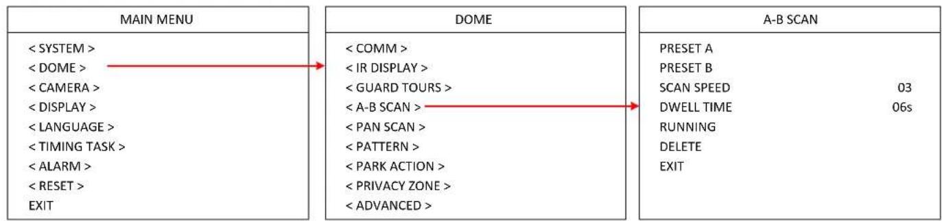
PRESET A: Set up A point from preset 0 to 64. To save the position, activate preset 1.
PRESET B: Set up B point from preset 0 to 64. To save the position, activate preset 1.
SCAN SPEED: A-B scan speed can be set up from 1 to 64.
DWELL TIME: Dwell time can be set up from 2s to 60s.
RUNNING: Enter to activate the A-B scan function.
DELETE: Enter to delete the setting of A-B scan. The preset points will display as 0.
EXIT: Exit the current menu.
4.2.5 PAN SCAN
flowchart
graph LR
    A["MAIN MENU"] --> B["DOME"]
    B --> C["PAN SCAN"]

    A1["< SYSTEM >"] --> A2["< COMM >"]
    A3["< DOME >"] --> A4["< IR DISPLAY >"]
    A5["< CAMERA >"] --> A6["< GUARD TOURS >"]
    A7["< DISPLAY >"] --> A8["< A-B SCAN >"]
    A9["< LANGUAGE >"] --> A10["< PAN SCAN >"]
    A11["< TIMING TASK >"] --> A12["< PATTERN >"]
    A13["< ALARM >"] --> A14["< PARK ACTION >"]
    A15["< RESET >"] --> A16["< PRIVACY ZONE >"]
    A17["EXIT"] --> A18["< ADVANCED >"]

    B1["< COMM >"] --> B2["< PATTERN >"]
    B3["< PARK ACTION >"] --> B4["< PRIVACY ZONE >"]
    B5["< PATTERN >"] --> B6["< PARK ACTION >"]
    B7["< PATTERN >"] --> B8["< PARK ACTION >"]
    B9["< PATTERN >"] --> B10["< PARK ACTION >"]
    B11["< PARK ACTION >"] --> B12["< PARK ACTION >"]
    B13["< PARK ACTION >"] --> B14["< PARK ACTION >"]
    B15["< PARK ACTION >"] --> B16["< PARK ACTION >"]
    B17["< PARK ACTION >"] --> B18["< PARK ACTION >"]
    B19["< PARK ACTION >"] --> B20["< PARK ACTION >"]
    B21["< PARK ACTION >"] --> B22["< PARK ACTION >"]
    B23["< PARK ACTION >"] --> B24["< PARK ACTION >"]
    B25["< PARK ACTION >"] --> B26["< PARK ACTION >"]
    B27["< PARK ACTION >"] --> B28["< PARK ACTION >"]
    B29["< PARK ACTION >"] --> B30["< PARK ACTION >"]
    B31["< PARK ACTION >"] --> B32["< PARK ACTION >"]
    B33["< PARK ACTION >"] --> B34["< PARK ACTION >"]
    B35["< PARK ACTION >"] --> B36["< PARK ACTION >"]
    B37["< PARK ACTION >"] --> B38["< PARK ACTION >"]
    B39["< PARK ACTION >"] --> B40["< PARK ACTION >"]
    B41["< PARK ACTION >"] --> B42["< PARK ACTION >"]
    B43["< PARK ACTION >"] --> B44["< PARK ACTION >"]
    B45["< PARK ACTION >"] --> B46["< PARK ACTION >"]
    B47["< PARK ACTION >"] --> B48["< PARK ACTION >"]
    B49["< PARK ACTION >"] --> B50["< PARK ACTION >"]
    B51["< PARK ACTION >"] --> B52["< PARK ACTION >"]
    B53["< PARK ACTION >"] --> B54["< PARK ACTION >"]
    B55["< PARK ACTION >"] --> B56["< PARK ACTION >"]
    B57["< PARK ACTION >"] --> B58["< PARK ACTION >"]
    B59["< PARK ACTION >"] --> B60["< PARK ACTION >"]
    B61["< PARK ACTION >"] --> B62["< PARK ACTION >"]
    B63["< PARK ACTION >"] --> B64["< PARK ACTION >"]
    B65["< PARK ACTION >"] --> B66["< PARK ACTION >"]
    B67["< PARK ACTION >"] --> B68["< PARK ACTION >"]
    B69["< PARK ACTION >"] --> B70["< PARK ACTION >"]
    B71["< PARK ACTION >"] --> B72["< PARK ACTION >"]
    B73["< PARK ACTION >"] --> B74["< PARK ACTION >"]
    B75["< PARK ACTION >"] --> B76["< PARK ACTION >"]
    B77["< PARK ACTION >"] --> B78["< PARK ACTION >"]
    B79["< PARK ACTION >"] --> B80["< PARK ACTION >"]
    B81["< PARK ACTION >"] --> B82["< PARK ACTION >"]
    B83["< PARK ACTION >"] --> B84["< PARK ACTION >"]
    B85["< PARK ACTION >"] --> B86["< PARK ACTION >"]
    B87["< PARK ACTION >"] --> B88["< PARK ACTION >"]
    B89["< PARK ACTION >"] --> B90["< PARK ACTION >"]
    style A fill:#f9f,stroke:#333
    style C fill:#ccf,stroke:#333
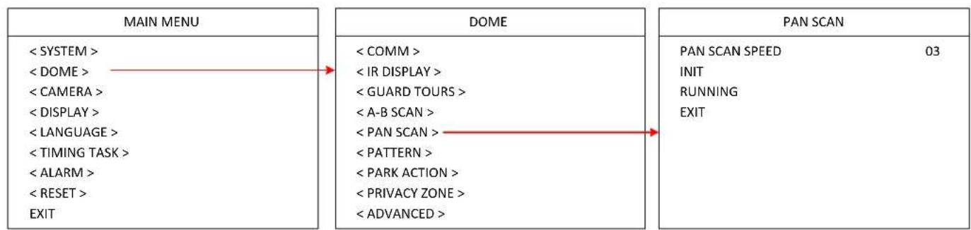
PAN SCAN SPEED: Set up the PAN scan speed from 1 to 64. PAN Scan supports 360°clockwise continuous scan.
INIT: Enter to initialize the PAN Scan speed to default value.
RUNNING: Enter to activate the PAN scan function.
EXIT: Exit the current menu.
4.2.6 PATTERN
flowchart
graph LR
    A["MAIN MENU"] --> B["DOME"]
    B --> C["PATTERN"]

    A1["< SYSTEM >"] --> A2["< COMM >"]
    A3["< DOME >"] --> A4["< IR DISPLAY >"]
    A5["< CAMERA >"] --> A6["< GUARD TOURS >"]
    A7["< DISPLAY >"] --> A8["< A-B SCAN >"]
    A9["< LANGUAGE >"] --> A10["< PAN SCAN >"]
    A11["< TIMING TASK >"] --> A12["< PATTERN >"]
    A13["< ALARM >"] --> A14["< PARK ACTION >"]
    A15["< RESET >"] --> A16["< PRIVACY ZONE >"]
    A17["EXIT"] --> A18["< ADVANCED >"]

    B1["< COMM >"] --> B2["< PATTERN NO 01 SETTING RUNNING DELETE EXIT"]
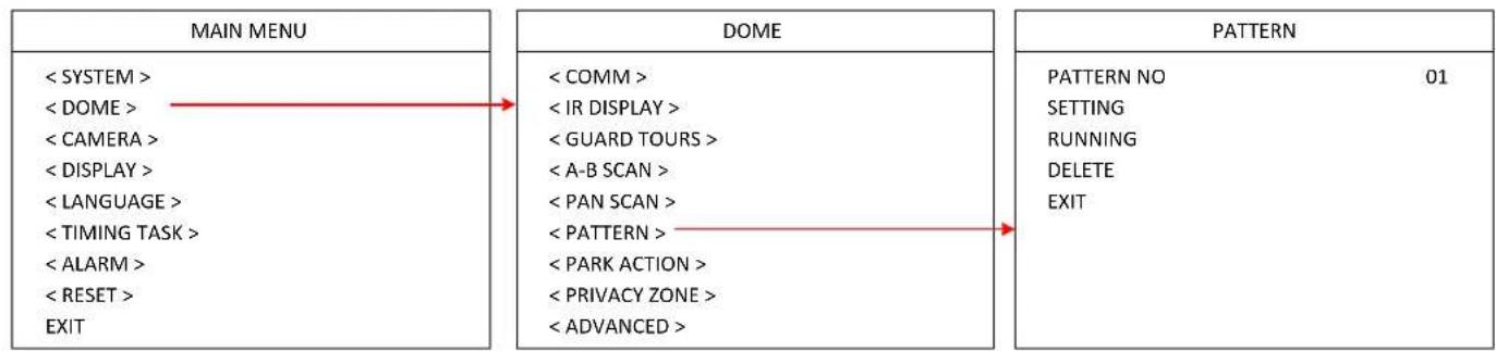
PATTERN NO: Select a number to start setting the Pattern function. Up to 4 patterns can be set up.
SETTING: Enter to set up the pattern function.
RUNNING: Enter to activate the pattern function.
DELETE: Enter to delete the setting of this pattern.
EXIT: Exit the current menu.
4.2.7 PARK ACTION
flowchart
graph LR
    A["MAIN MENU"] --> B["DOME"]
    B --> C["PARK ACTION"]

    A1["< SYSTEM >"] --> A2["< DOME >"]
    A2 --> A3["< CAMERA >"]
    A3 --> A4["< DISPLAY >"]
    A4 --> A5["< LANGUAGE >"]
    A5 --> A6["< TIMING TASK >"]
    A6 --> A7["< ALARM >"]
    A7 --> A8["< RESET >"]
    A8 --> A9["EXIT"]

    B1["< COMM >"] --> B2["< IR DISPLAY >"]
    B2 --> B3["< GUARD TOURS >"]
    B3 --> B4["< A-B SCAN >"]
    B4 --> B5["< PAN SCAN >"]
    B5 --> B6["< PATTERN >"]
    B6 --> B7["< PARK ACTION >"]
    B7 --> B8["< PRIVACY ZONE >"]
    B8 --> B9["< ADVANCED >"]

    C1["PARK MODE OFF"] --> C2["PARK TIME 01M"]
    C2 --> C3["SETTING"]
    C3 --> C4["CALL"]
    C4 --> C5["DELETE"]
    C5 --> C6["EXIT"]
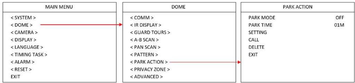
PARK MODE: Select a park mode. Options include Off, A-B Scan, 360, Home, Tour1 and Pattern1.
PARK TIME: Select a park time from 1\~60 mins.
SETTING: Move to the desired position and save the settings.
CALL: Enter to activate the park function.
DELETE: Delete the settings.
EXIT: Exit the current menu.
4.2.8 PRIVACY ZONE
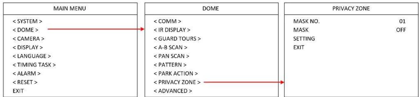
This speed dome camera does not support the Privacy Zone function.
flowchart
graph LR
    A["MAIN MENU"] --> B["DOME"]
    B --> C["PRIVACY ZONE"]

    A1["< SYSTEM >"] --> A2["< DOME >"]
    A2 --> A3["< CAMERA >"]
    A3 --> A4["< DISPLAY >"]
    A4 --> A5["< LANGUAGE >"]
    A5 --> A6["< TIMING TASK >"]
    A6 --> A7["< ALARM >"]
    A7 --> A8["< RESET >"]
    A8 --> A9["EXIT"]

    B1["< COMM >"] --> B2["< IR DISPLAY >"]
    B2 --> B3["< GUARD TOURS >"]
    B3 --> B4["< A-B SCAN >"]
    B4 --> B5["< PAN SCAN >"]
    B5 --> B6["< PATTERN >"]
    B6 --> B7["< PARK ACTION >"]
    B7 --> B8["< PRIVACY ZONE >"]
    B8 --> B9["< ADVANCED >"]

    C1["MASK NO. 01"] --> C2["MASK OFF"]
    C3["SETTING"] --> C4["EXIT"]
4.2.9 ADVANCED
flowchart
graph LR
    A["MAIN MENU"] --> B["DOME"]
    A --> C["ADVANCED"]

    subgraph MAIN MENU
        A1["< SYSTEM >"]
        A2["< DOME >"]
        A3["< CAMERA >"]
        A4["< DISPLAY >"]
        A5["< LANGUAGE >"]
        A6["< TIMING TASK >"]
        A7["< ALARM >"]
        A8["< RESET >"]
        A9["EXIT"]
    end

    subgraph DOME
        B1["< COMM >"]
        B2["< IR DISPLAY >"]
        B3["< GUARD TOURS >"]
        B4["< A-B SCAN >"]
        B5["< PAN SCAN >"]
        B6["< PATTERN >"]
        B7["< PARK ACTION >"]
        B8["< PRIVACY ZONE >"]
        B9["< ADVANCED >"]
    end

    subgraph ADVANCED
        C1["PWR ON ACT ACTION"]
        C2["RATIO SPEED ON"]
        C3["AUTO FLIP ON"]
        C4["OTHERS EXIT"]
    end
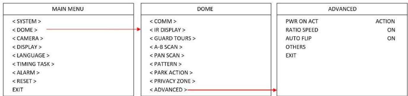
PWR ON ACTION: Power on action can be set as Action (memory), Off, A-B Scan, 360, Home, Tour1 and Pattern1. When power-on the dome, the dome will activate the selected action.
RATIO SPEED: Ratio speed can be set up as ON or OFF. Intelligent pan and tilt speed is variable based on the zoom factor. When zooming in, the speed will become slower and when zooming out, the speed will become faster.
AUTO FLIP: Auto flip can be set up as ON or OFF status.
OTHERS: This speed dome camera does not support this function.
EXIT: Exit the current menu.
4.3 Camera
| MAIN MENU | CAMERA | ||
| < SYSTEM > | CAM | AUTO | |
| < DOME > | ZOOM SPEED | QUICK | |
| < CAMERA > | DIGITAL ZOOM | OFF | |
| < DISPLAY > | FOCUS | AUTO | |
| < LANGUAGE > | IRIS | AUTO | |
| < TIMING TASK > | BLC | OFF | |
| < ALARM > | FREEZE | OFF | |
| < RESET > | EXIT | ||
| EXIT | |||
CAM: Optionally select a brand of the speed dome camera to be displayed.
ZOOM SPEED: Select a zoom speed for the speed dome camera.
DIGITAL ZOOM: Turn on or turn off the Digital Zoom function for the speed dome camera.
FOCUS: Select Auto or Manual for the focus mode.
IRIS: Select Auto or Manual for the IRIS. Auto IRIS is recommended.
BLC: Turn on or turn off the BLC function.
FREEZE: Turn on or turn off the Video Freeze function.
EXIT: Exit the current menu.
4.4 Display
| MAIN MENU | DISPLAY | |
| < SYSTEM > | P AND T | OFF |
| < DOME > | ZOOM | OFF |
| < CAMERA > | ACTION | ON |
| < DISPLAY > | DOME ID | ON |
| < LANGUAGE > | COMM | ON |
| < TIMING TASK > | TIME | OFF |
| < ALARM > | EXIT | |
| < RESET > | ||
| EXIT | ||
P AND T: Turn on or off to display the pan and tilt degree on the screen.
ZOOM: Turn on or off to display the zoom information.
ACTION: Turn on or off to display the current action, such as A-B Scan, Call Preset, Save preset, Call Park Action, Pan Scan and etc.
DOME ID: Turn on or off to display the dome ID on the top-left corner of the screen.
COMM: Turn on or off to display the communication speed on the top-left corner of the screen.
TIME: Turn on or off to display the system time on the screen.
EXIT: Exit the current menu.
4.5 Language
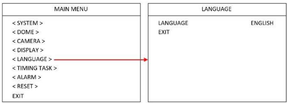
You can select a language for the dome.
flowchart
graph LR
    A["MAIN MENU"] --> B["LANGUAGE"]
    A --> C["LANGUAGE"]
    A --> D["LANGUAGE"]
    B --> E["LANGUAGE"]
    B --> F["LANGUAGE"]
    B --> G["LANGUAGE"]
    C --> H["LANGUAGE"]
    C --> I["LANGUAGE"]
    C --> J["LANGUAGE"]
    D --> K["LANGUAGE"]
    D --> L["LANGUAGE"]
    D --> M["LANGUAGE"]
    style A fill:#f9f,stroke:#333
    style B fill:#ccf,stroke:#333
    style C fill:#cfc,stroke:#333
    style D fill:#fcc,stroke:#333
4.6 Timing Task
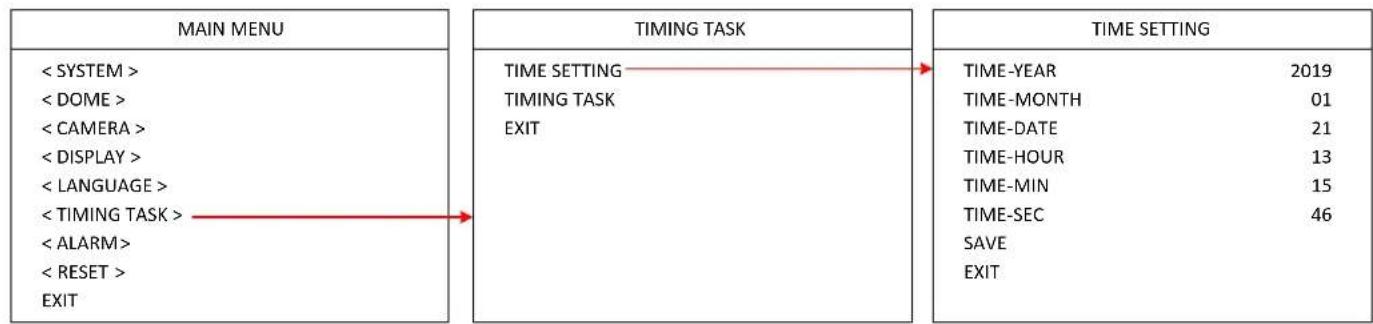
4.6.1 TIME SETTING
You can set up the system date and time in this menu.
flowchart
graph LR
    A["MAIN MENU"] --> B["TIMING TASK"]
    B --> C["TIME SETTING"]
    C --> D["TIME-YEAR 2019"]
    C --> E["TIME-MONTH 01"]
    C --> F["TIME-DATE 21"]
    C --> G["TIME-HOUR 13"]
    C --> H["TIME-MIN 15"]
    C --> I["TIME-SEC 46"]
    C --> J["SAVE"]
    C --> K["EXIT"]
    A --> L["< SYSTEM >"]
    A --> M["< DOME >"]
    A --> N["< CAMERA >"]
    A --> O["< DISPLAY >"]
    A --> P["< LANGUAGE >"]
    A --> Q["< TIMING TASK >"]
    A --> R["< ALARM >"]
    A --> S["< RESET >"]
    A --> T["EXIT"]
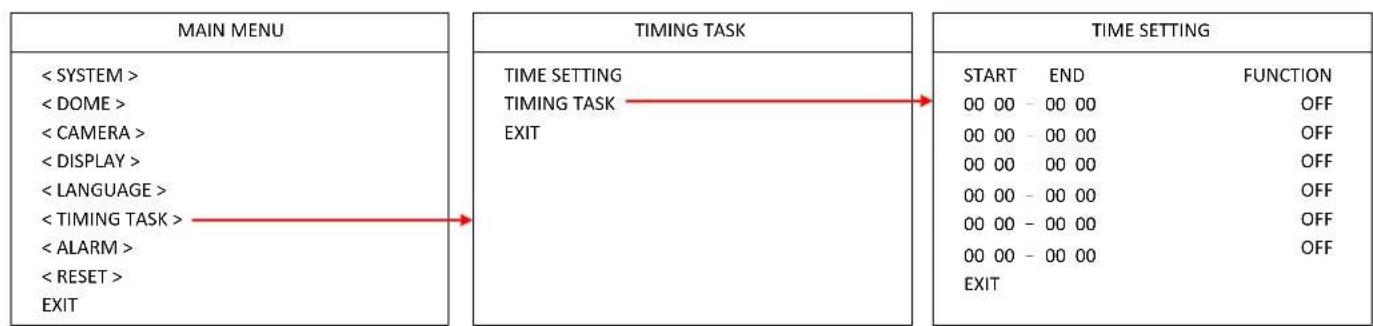
4.6.2 TIME TASK
You can set up time task in this menu. Up to 6 time schedules can be set up for functions including A-B Scan, 360 Pan, Tour1, Tour2, Tour3, Tour4, Pattern1, Pattern2, Pattern3 and Pattern4.
flowchart
graph LR
    A["MAIN MENU"] --> B["TIMING TASK"]
    B --> C["TIME SETTING"]
    C --> D["TIME SETTING"]
    D --> E["START END FUNCTION"]
    E --> F["00 00 - 00 00 OFF"]
    E --> G["00 00 - 00 00 OFF"]
    E --> H["00 00 - 00 00 OFF"]
    E --> I["00 00 - 00 00 OFF"]
    E --> J["00 00 - 00 00 OFF"]
    E --> K["EXIT"]
    A --> L["< SYSTEM >"]
    A --> M["< DOME >"]
    A --> N["< CAMERA >"]
    A --> O["< DISPLAY >"]
    A --> P["< LANGUAGE >"]
    A --> Q["< TIMING TASK >"]
    A --> R["< ALARM >"]
    A --> S["< RESET >"]
    A --> T["EXIT"]
4.7 Alarm
| MAIN MENU | ALARM |
| < SYSTEM > | ALARM OFF |
| < DOME > | PATROL TIME 06S |
| < CAMERA > | ALARM LINKAGE OFF |
| < DISPLAY > | ALARM 1 01 |
| < LANGUAGE > | ALARM 2 02 |
| < TIMING TASK > | ALARM 3 03 |
| < ALARM > | ALARM 4 04 |
| < RESET > | RELEASE TIME OFF |
| EXIT | EXIT |
ALARM: Turn on or off the Alarm function.
PATROL TIME: Patrol time can be set up from 2\~60s.
ALARM LINKAGE: Turn on or off the Alarm Linkage function. If On is selected, you can further set up an alarm linkage preset point in the below field.
ALARM 1: To run alarm 1, presets 1-64 are available.
ALARM 2: To run alarm 2, presets 1-64 are available.
ALARM 3: To run alarm 3, presets 1-64 are available.
ALARM 4: To run alarm 4, presets 1-64 are available.
RELEASE TIME: You can set up the alarming release time from 2-60s; or select Off to turn off the release time.
EXIT: Exit the current menu.
4.8 Reset
| MAIN MENU | RESET |
| < SYSTEM > | DOME RESTART |
| < DOME > | SYS DATA |
| < CAMERA > | CAM DATA |
| < DISPLAY > | PRESET |
| < LANGUAGE > | EXIT |
| < TIMING TASK > | |
| < ALARM > | |
| < RESET > | |
| EXIT |
DOME RESTART: Enter to restart the speed dome camera.
SYS DATA: Enter to restore the system data to factory default.
CAM DATA: Enter to restore the dome data to factory default.
PRESET: Enter to delete the setup preset points.
EXIT: Exit the current menu.
- Specifications
| Product Model | EPA6220 | EPA6236 |
| Pickup Device | Sony CMOS sensor | |
| Output Pixels (H x V) | 1920 x 1080 (30 / 25 FPS) | |
| Lens | 20x optical zoom, 4.7~94mm | 36x optical zoom, 4.6~165mm |
| Video Format | AHD / TVI / CVI / CVBS switchable | |
| System Format | NTSC / PAL switchable | |
| Min. Illumination | Color: 0.01Lux ; B/W: 0.001Lux | |
| S/N Ratio ≥50dB | ||
| Zoom Ratio | Max. 20x (optical) | Max. 36x (optical) |
| True Day / Night | Supported | |
| BLC | On / Off | |
| WDR | D-WDR (auto) | |
| AGC | Auto | |
| WB | Auto | |
| Motion Detection | Not supported | |
| Defog | Not supported | |
| Privacy Mask | Not supported | |
| Alarm | Not supported | |
| Focus Control | Auto / Manual | |
| OSD Menu | Supported | |
| Video Output | 1Vp-p, 75Ω | |
| IR LED | 8 units | |
| IR Range | 150m / 492ft. | |
| Auto Flip | Horizontal 180°, Vertical 93° | |
| Preset Points | 220 preset points (dwell time 01-60s) | |
| A-B Scan | User programmable (scan speed 1-64) | |
| Tour | 8 tours (max.16 preset points each tour) | |
| PWR on Action | Action (Memory), Off, AB Scan, 360, Home, Tour1, Pattern1 | |
| Park Mode | Off, AB Scan, 360, Home, Tour1, Pattern1 (park time 1-60m) | |
| Pattern Scan | 4 patterns (max.15 minutes, max.512 commands) | |
| Time Scheduling | 6 tasks (AB Scan, 360 Pan, Tour 1-4, Pattern 1-4) | |
| Rotation Range | Pan: 0°~360°, Tilt: 0°~93° | |
| Rotation Speed | Pan: 0~480°/s, Tilt:0~240°/s | |
| Communication | RS-485, Coaxial | |
| Communication Speed | 1200 / 2400 / 4800 / 9600bps | |
| Built-in Protocols | Pelco-P / Pelco-D (auto) | |
| Address Editable | Supported (OSD switch) | |
| ID Address 0 ~ 255 | ||
| Power Source | 12VDC, 4A / 24VAC~, 3A | |
| Power Consumption ≤ 25W | ||
| Weather Resistance | IP66 | |
| Operating Temperature | -40°C ~ 60°C ≤ 95% / -40°F ~ 140°F ≤ 95% | |
| Package Size (W x D x H) | 310 x 310 x 440mm / 12.2" x 12.2" x 17.32" | |
| Weight | 12VDC: 6.1kg / 13.45lb24VAC~: 7.15kg / 15.76lb | |
| Certificates CE, FCC | ||
Appendix
A. Shortcut Commands
The speed dome camera supports AHD, TVI, CVI and CVBS video formats, which are switchable via shortcut commends. The shortcut commends are only compliant with Pelco-D and its extended protocol. Users can use the shortcut commend to enable the functions described as below:
| Preset No. | Function | Preset No. | Function |
| 81 (41) | Auto day/night | 97 | Call tour 2 |
| 82 (42) | Switch to night | 98 (38) | Call tour 1 |
| 83 | Switch to day | 99 (39) | Pan scan |
| 84 | Force on far light | Twice 137 | Switch to AHD |
| 85 | Force on near light | Twice 138 | Switch to TVI |
| 92 | A-B Scan | Twice 139 | Switch to CVI |
| 94 | OSD off | Twice 140 | Switch to CVBS |
| 95 | OSD on | Twice 115 | Switch to NTSC |
| 96 | Call tour 3 | Twice 116 | Switch to PAL |
Note: If there is no video or the video is displaying black and white, please check whether the video signal output (NTSC / PAL) is compliant with the system format of your region.
B. Troubleshooting
| Issue Possible Reason | Solution | |
| After power is applied, there is no motion (self-test) and no video image | Cable harness is improperly connected | Verify that the orientation of the connector input |
| Input power voltage is too low | Verify the voltage of the input power | |
| Power supply is not working | Change a new power supply | |
| Self-test is normal, but cannot control dome | Wrong communication settings | Set the correct protocol, baud rate and address of dome |
| Improper connection of control cable (polarity) | Verify the polarity of the RS485 connection as per the instruction manual | |
| Noise after self-testing | Mechanical obstruction Verify and correct it | |
| Camera module is not installed correctly | Check the module installation | |
| Low power | Change the correct power supply | |
| Image is not stable | Low power | Check the power supply or make sure the power input |
| Video cable is improperly contacted | Verify the contact of the video cable | |
| Image is blurring | Camera is on manual focus | Change to auto focus |
| The lens is dusted Clean the lens | ||
| Control to the dome is not smooth | Power is too low | Change the DC 12V Power supply |
| Communication distance is too far | Make sure the distance is in the allowed range | |
| RS485 cable is not properly connected | Make sure the RS485 is properly connected | |
| Too many domes connected | Make sure the quantity of the connected domes are allowed | |
EverFocus Electronics Corp.
EverFocus Taiwan:
2F., No.12, Ln. 270, Sec. 3, Beishen Rd., Shenkeng
Dist., New Taipei City 222, Taiwan
TEL: +886 2 2662 2338
FAX: +886 2 2662 3632
www.everfocus.com.tw
marketing@everfocus.com.tw
EverFocus China - Beijing:
Room 609, Technology Trade Building,
Shangdi Information Industry Base,
Haidian District, Beijing 100085, China
TEL: +86 10 6297 3336\~39
FAX: +86 10 6297 1423
www.everfocus.com.cn
marketing@everfocus.com.cn
EverFocus USA - California:
1801 Highland Avenue, Unit A, Duarte, CA 91010, USA
TEL: +1 626 844 8888
FAX: +1 626 844 8838
www.everfocus.com
sales@everfocus.com
EverFocus China - Shenzhen:
4F, No. 2, D4 Building, Wan Yelong
Industrial Park, Tangtou Road, Shiyan,
Baoan, Shenzhen, Guangdong 518101, China
TEL: +86 755 2765 1313
FAX: +86 755 2765 0337
www.everfocus.com.cn
marketing@everfocus.com.cn
EverFocus Japan:
3F, Kuramochi, Building II
2-2-3 Koto-Bashi, Sumida-Ku,
Tokyo, 130-0022, Japan
TEL: +81-3-5625-8188
FAX: +81 3 5625 8189
www.everfocus.co.jp
info@everfocus.co.jp
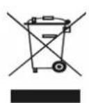
Your EverFocus product is designed and manufactured with high quality materials and components which can be recycled and reused.
This symbol means that electrical and electronic equipment, at their end-of-life, should be disposed of separately from your household waste.
Please, dispose of this equipment at your local community waste collection/sampling process
In the European Union there are separate collection systems for used electrical and electronic product. Please, help us to conserve the environment we live in!
- EverFocus
- Disclaimer
- Copyright
- About this document
- Regulatory Notices
- FCC Notice "Declaration of Conformity Information"
- Precautions
- CONTENTS
- Introduction....1
- Installation....3
- OSD Menu Tree....8
- OSD Menu 10
- Specifications 19
- Appendix....21
- Introduction
- Features
- Dimensions
- Packing List
- Note:
- Optional Accessories
- Installation
- Wall Mounting
- Corner Mounting
- Pole Mounting
- Ceiling Mounting
- Cable Connection
- Coaxial and RS-485 Cables
- Power Cable
- OSD Menu
- System
- Dome
- COMM
- IR DISPLAY
- GUARD TOUR
- A-B SCAN
- PAN SCAN
- PATTERN
- PARK ACTION
- PRIVACY ZONE
- ADVANCED
- Camera
- Display
- Language
- Timing Task
- TIME SETTING
- TIME TASK
- Alarm
- Reset
- Appendix
- Shortcut Commands
- Troubleshooting
- EverFocus Electronics Corp.
- EverFocus Taiwan:
- EverFocus China - Beijing:
- EverFocus USA - California:
- EverFocus China - Shenzhen:
- EverFocus Japan:
Brand : EverFocus
Model : EPA6220
Category : Security Camera