EPTZ500 - Security Camera EverFocus - Free user manual and instructions
Find the device manual for free EPTZ500 EverFocus in PDF.


| Product Type | Indoor PTZ Speed Dome Security Camera |
| Brand | EverFocus |
| Model | EPTZ500 |
| Image Sensor | 1/4" Sony Super HAD CCD |
| Video Format | NTSC or PAL (switchable) |
| Effective Pixels | 768 (H) × 494 (V) (NTSC) / 752 (H) × 582 (V) (PAL) |
| Horizontal Resolution | 480 TVL |
| Minimum Illumination | 1.0 lux |
| Signal-to-Noise Ratio | ≥ 50 dB (AGC Off) |
| Lens | 18x optical zoom, f=4.1–73.8 mm, F1.4–F3.0 |
| Digital Zoom | 12x (total 216x) |
| Pan Range | 360° continuous |
| Pan Speed | 0.1°/s to 360°/s (1–239 grades) |
| Tilt Range | 0° to 90° (pendulum) |
| Tilt Speed | 0.1°/s to 180°/s (manual), 0.1°/s to 360°/s (to preset) |
| Preset Positions | 192 |
| Cruise Tours | 16 tours, each with up to 16 preset positions |
| Alarm Inputs/Outputs | 4 inputs, 1 output (N.O./N.C. configurable) |
| Communication | RS-485, up to 256 cameras daisy-chained |
| Built-in Protocols | EVF, Pelco-D, Pelco-P, Type-A, Plus-D, Auto |
| Power Supply | 24 VAC, 18 W (without heater) |
| Operating Temperature | 0°C to 50°C (32°F to 122°F) |
| Dimensions (W×H) | 208.5 mm × 221.6 mm (8.2" × 8.7") |
| Weight | 2.15 kg (4.8 lbs) |
| Included Accessories | Wall mount bracket, power adapter, installation kit, gloves |
| Certifications | CE, FCC |
Frequently Asked Questions - EPTZ500 EverFocus
User questions about EPTZ500 EverFocus
0 question about this device. Answer the ones you know or ask your own.
Ask a new question about this device
Download the instructions for your Security Camera in PDF format for free! Find your manual EPTZ500 - EverFocus and take your electronic device back in hand. On this page are published all the documents necessary for the use of your device. EPTZ500 by EverFocus.
USER MANUAL EPTZ500 EverFocus
natural_image
White spherical security camera with 'EverFocus' logo on dome (no additional text or symbols visible)Table of Contents
1. EPTZ900/500 OVERVIEW....1-3
1.1. Introduction 1-3
1.2. Specifications....1-5
1.3. Feature 1-7
1.3.1. Profile of EPTZ900/500....1-7
1.3.2. Base Board 1-8
1.3.3. EPTZ900/500 Control Board....1-9
1.4. EPTZ900/500 Connection....1-10
1.5. EPTZ900/500 Quick Operation Guide (Work with EKB500) ...... 1-11
2. EPTZ900/500 INSTALLATION 2-12
2.1. Packing List 2-12
2.2. Cable Needed....2-12
Power Cable....2-12
Video Cable....2-13
Control Cable....2-13
Alarm Cable 2-13
2.3. Initial Setup....2-13
2.3.1. Address Setting....2-14
2.3.2. Communication Protocol Setting....2-17
2.3.3. Transmission Speed Setting (Baud Rate Setting) 2-17
2.3.4. Video Format Setting 2-18
2.3.5. RS-485 Bus Terminator Resistance 2-18
2.4. Rack and Speed Dome Installation 2-20
2.4.1. Installation Requirements....2-20
2.4.2. EPTZ900 Dome Camera Wall Mount Installation 2-20
2.4.3. EPTZ500 Dome Camera Installation 2-24
2.5. Separately Sold Accessories....2-27
2.5.1. Pole mount....2-27
2.5.2. Pole adapter....2-27
2.5.3. Corner mount 2-27
2.5.4. Multi-Function Keyboard Controller 2-27
3. EPTZ900/500 CAMERA SETUP MENU....3-28
3.1. Structure of the Setup Menu 3-28
3.1.1. Camera Setup Menu....3-29
4. EPTZ900/500 FUNCTION SETUP AND OPERATION...4-33
4.1. Manual Control Mode 4-33
4.2. Auto Pan Mode 4-33
4.3. Position Setting 4-33
4.4. Tour Mode 4-34
4.5. Alarm Link to a Position/Tour....4-35
4.6. Other operations 4-35
APPENDIX B: Protocol 4-37
1. EPTZ900/500 OVERVIEW
1.1. Introduction
EPTZ900/500, an intelligent high-speed dome camera is ready to secure your property with its omni-directional and exact monitoring. An 18X optical and 12X digital zoom combining with a high-performance chip makes captured images clear and vivid. The other powerful camera functions this type of speed dome equips with:
➢ PAL / NTSC image format suppose.
➢ Auto and fast focus increases the searching speed and precision.
➢ Auto Iris adjusts the monitoring image to the best brightness.
White Balance function makes the shades of color more natural in different light conditions.
BLC (Backlight Compensation) function makes objects clear in a high illumination background.
Color / B&W images auto switching to enhance the sensitivity in a low light condition or at night.
Furthermore, the micro control unit enables camera a nimble and exact movement from minimal 0.01^/sec to maximal 360^/sec . It can go to every preset position in 1 second. It also has other advantages such as:
➢ 192 preset positions are available.
➢ 16 cruise tours can be set, and each tour contains up to 16 positions.
Up to256 speed domes can be supported on a RS485 bus when all speed domes are controlled by multi-function keyboard controller.
➢ Auto heater and fan to fit all kinds of temperature.
➢ Provide 4 alarm inputs and 1 alarm output.
All of the features make the intelligent high-speed dome camera works for a wide range and demanding application such as banks, airports, stations, casinos, streets of cities, intelligent buildings, and etc.
1.2. Specifications
| Model | EPTZ900 | EPTZ500 |
| Pickup Device 1/4" type Sony Super HAD CCD | ||
| Video Format NTSC or PAL | ||
| Scanning System NTSC: 525 TV lines, 60 fields/secPAL: 625 TV lines, 50 fields/sec | ||
| Picture Elements 768 x 494 (NTSC), 752 x 582 (PAL) | ||
| Horizontal Resolution 480 TVL | ||
| Sensitivity | 1.0 | |
| S/N Ratio (AGC OFF) Over 50dB | ||
| Electronic Shutter 1/50~1/10,000 (s) | ||
| Digital Slow Shutter No | ||
| Shutter Selection No | ||
| Lens Type 18x optical zoom, f=4. | mm (wide) to 73.8mm (tele), F1.4 to F3.0 | |
| Zoom Ratio 216x max (18x Optical and 12x Digital Zoom) | ||
| Auto ICR No | ||
| Black Light Comp. | ON/OFF | |
| Auto Gain Control | Auto | |
| White Balance | Auto/Indoor/Outdoor | |
| Video Output | BNC 1.0Vp-p, 75ohm | |
| Sync. Mode | Line Lock/Internal Sync | |
| Power Source | 24VAC | |
| Power Consumption | 18W; 70W with heater | 18W |
| Operating Temperature | -40°C~50°C; -40°F~122°F | 0°C~50°C; 32°F~122°F |
| Operating Moisture | ≤95% | |
| Communication | RS-485 | |
| Communication Speed | 1200/2400/4800/9600bps | |
| Horizontal Rotation Speed | 0.1°/s-360°/s (1-239 grade shift gears) | |
| Horizontal Rotation Range | 360° unlimited rotation | |
| Tilt Rotation Range | 90° pendulum motion | |
| Auto Flip | Rotates 180° when camera tilts to the vertical position | |
| Auto Zoom Speed Control | Control speed auto-adjusted according to zoom length changing | |
| Auto Pan, 2 Points Scanning | Can set freely | |
| Auto Pan Speed | 1-239 grade available | |
| Dwell Time (2 points) | 1-239 second available | |
| Preset Positions | 192 positions | |
| Running To Position Speed | 1-239 grade available,0.1°/s - 360°/s | |
| Dwell Time At Preset Position | 1-239 second available | |
| Tour | 16 | |
| Tour Point Per Group 16 preset positions | ||
| Fan, Heater (EPTZ900) Fan & Heater auto starts No | ||
| Position Accuracy ±0.1° | ||
| Alarm 4 in 1 out with tour/position | auto triggering | |
| Proportional Pan Speed Yes | ||
| Built-in menu for functions Yes | ||
| Built-in Protocols Auto, EVF, Plus-D, A-Type, Pelco-D, Pelco-P | ||
| Communication | RS485 | |
| Address editable through DIP switch | Yes | |
| Speed Dome Address 0-255 | ||
| Manual Pan/tilt speed Pan: 0.1° ~ 180°/s Tilt: 0.1° ~ 180°/s | ||
| Weatherproof Ratings | IP66 | Indoor |
| Dimensions | 218.5mm (W) x 267.5mm (H) / 8.6" (W) x 10.5" (H) | 208.5mm (W) x 221.6mm (H) / 8.2" (W) x 8.7" (H) |
| Weight | 4.2kg/9.25lbs | 2.15kg/4.8lbs |
| Certifications | CE; FCC | |
1.3. Feature
1.3.1. Profile of EPTZ900/500
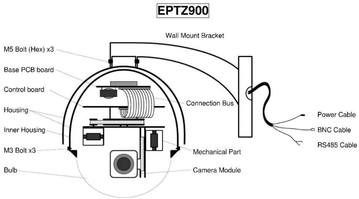
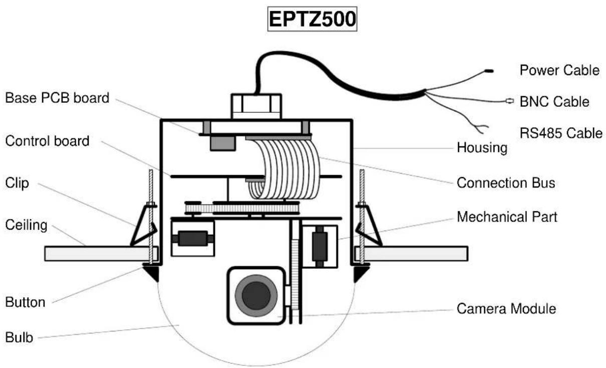
1.3.2. Base Board
The base board that is on the bottom of the housing connects to power cable, video cable, control cable, alarm cable, fan and heater (fan and heater are for EPTZ900 only). In order to connect to cables, the board needs to be taken off, and put back after finishing connecting to all cables. The connectors of cable names are marked on the board in white text. The details of the alarm connector (JP5) are shown on the APPENDIX A.
For EPTZ900, JP1, JP3 and JP6 that are two-pin connectors on the base board need to be taken off during installation. JP1 and JP3 are connectors for heater, and they can be switched. JP6 is a fan controller connector that turns on/off of the fan. The 3 cables are too short to be connected to a wrong connector when putting them back.
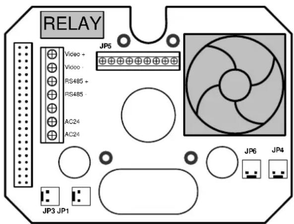
EPTZ900 Baseboard
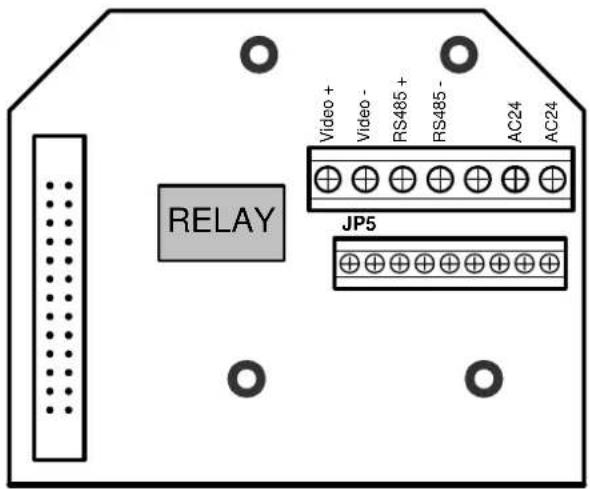
EPTZ500 Baseboard
1.3.3. EPTZ900/500 Control Board
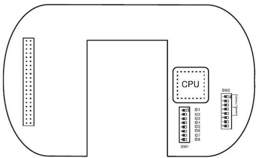
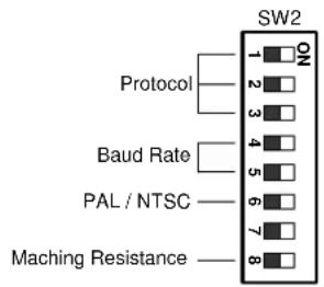
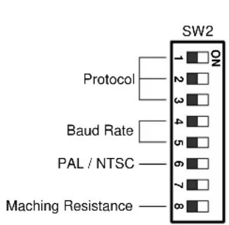
The PCB board with two dipswitches is the control board of speed dome. The two switches are used to set address, protocol, Baud Rate, video format and terminator resistance.
1.4. EPTZ900/500 Connection
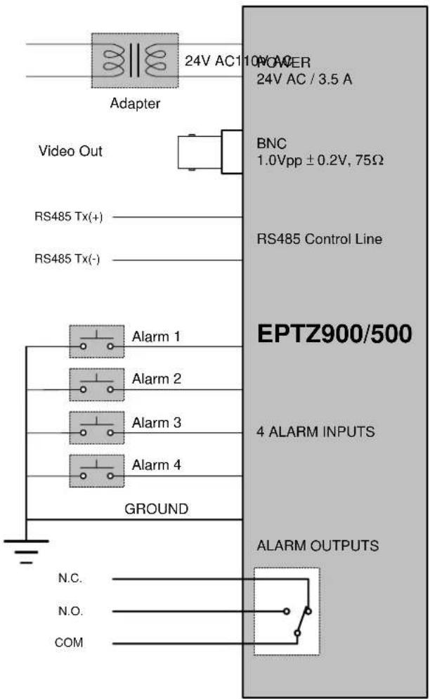
1.5. EPTZ900/500 Quick Operation Guide (Work with EKB500)
EPTZ900/500 and EKB500 (Keyboard) can work together by using factory default setting. You just need to connect cables by following the steps:
- Connect the RS485 cable to EPTZ900/500 and a Keyboard (EKB500).
- Connect a video cable from EPTZ900/500 to a monitor.
- Connect the power to the EPTZ900/500 and a Keyboard (EKB500).
After the speed dome finishes the self-test mode, you can start to operate the speed dome via the keyboard.
To operate the EPTZ900/500:
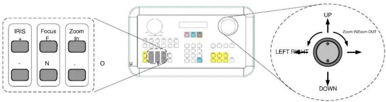
- Shift the Joystick up/down or right/left to view from camera.
- Turn the top of the Joystick to zoom in/out.
- Press Zoom In/Out, Focus F. /N. and IRIS +/- function keys to operate the EPTZ900/500.
2. EPTZ900/500 INSTALLATION
2.1. Packing List
There are 3 boxes that are housing, bulb and mechanical part with a camera module, one wall mount bracket, one power adapter and one accessory packet in the package.
The detail accessories list below:
Housing x1
Bulb x1
Mechanical part with a camera module x1
▶ Wall mount bracket x1
Adapter x1
▶ Accessory packet
✨ Glove x2
✿ M5 Hex Allen wrench x1
✨ Pin connector x1
✿ M5 screw (Hex) x3 for wall mount bracket fixing
✨ M3 screw x3 for bulb fixing
✨ Anchor nut and wall mount screw x4
2.2. Cable Needed
- Power Cable
An adapter with 24V AC/3.5A output provides the power to the speed dome. An extension power line may be needed.
Note: The input AC voltage range of an adapter depends on different area.
Please make sure the voltage range before installing.
- Video Cable
A BNC cable is used for connecting a speed dome to a DVR or a monitor. An amplifier may be needed if the video cable is too long.
- Control Cable
Basically, EPTZ900/500 uses a differential pair to connect to other devices by cascading. A cable that has low signal decline can be used as a control cable.
- Alarm Cable
An alarm cable is not included in the packing list. A suitable wire can be used as an alarm cable.
2.3. Initial Setup
Initial setup includes dome address, communication protocol, transmission speed, video format, and terminator resistance settings. All of the settings should be confirmed before the dome is installed. The control-related setting that is address, communication protocol and transmission speed have to be set consistently with the control device such as a keyboard or a DVR.
Notice: Please make sure the power is off before setting, and restart the speed dome to enable a new value after changing.
2.3.1. Address Setting
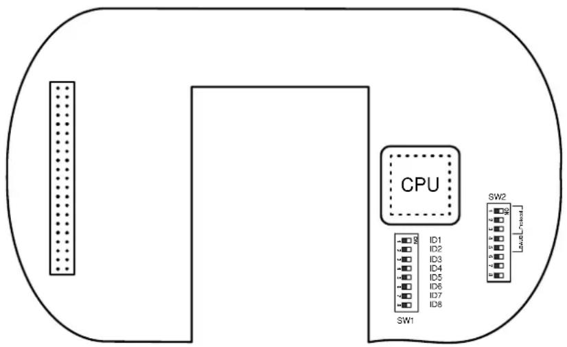
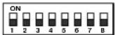
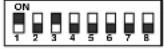
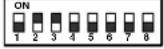
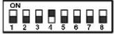
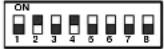
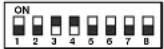
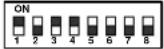
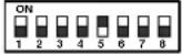
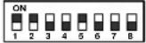
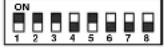
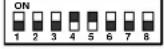
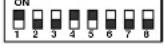
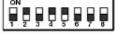
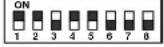
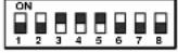
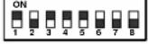
The address code of the EPTZ900/500 should be set to correspond properly with a control device to control multiple dome cameras. The address codes are made up by the dipswitch SW1 (8 bits) on the PCB board. The 8 bits dipswitch indicates the binary coded of the address, and there are 256 addresses can be selected (0 \~ 255, 2^8 = 256 ). It also means that there up to 256 dome cameras can cascade on the RS485 bus. The dipswitch setting and the indicated address are represented in the following chart.
Note: The factory default address is 1.
Notice: Please make sure the power is off before setting, and restart the speed dome to enable a new value after changing.
| Switch Address | Switch Address | Switch Address | Switch Address | ||||
 | 0 | 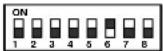 | 32 | 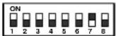 | 64 | 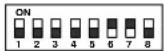 | 96 |
| 1 | 33 | 65 | 97 | ||||
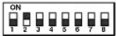 | 2 | 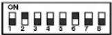 | 34 | 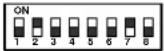 | 66 | 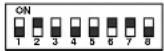 | 98 |
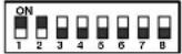 | 3 | 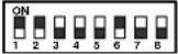 | 35 | 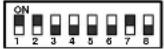 | 67 | 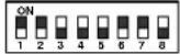 | 99 |
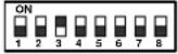 | 4 | 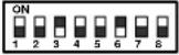 | 36 | 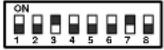 | 68 | 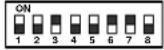 | 100 |
 | 5 | 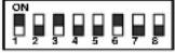 | 37 | 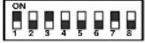 | 69 | 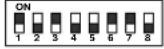 | 101 |
 | 6 | 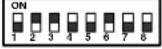 | 38 | 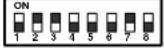 | 70 | 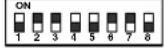 | 102 |
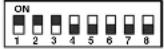 | 7 | 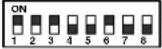 | 39 | 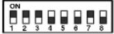 | 71 | 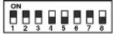 | 103 |
 | 8 | 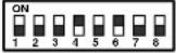 | 40 | 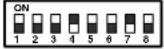 | 72 | 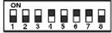 | 104 |
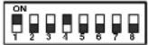 | 9 | 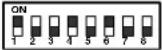 | 41 | 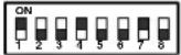 | 73 | 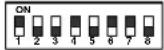 | 105 |
 | 10 | 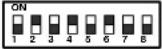 | 42 | 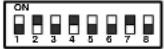 | 74 | 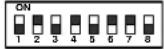 | 106 |
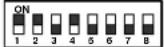 | 11 | 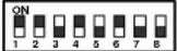 | 43 | 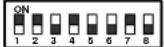 | 75 | 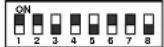 | 107 |
 | 12 | 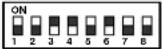 | 44 | 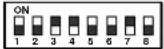 | 76 | 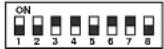 | 108 |
 | 13 | 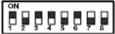 | 45 | 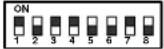 | 77 | 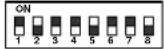 | 109 |
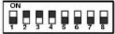 | 14 | 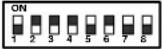 | 46 | 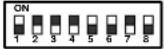 | 78 | 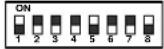 | 110 |
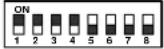 | 15 | 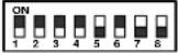 | 47 | 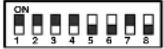 | 79 | 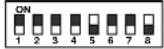 | 111 |
 | 16 | 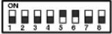 | 48 | 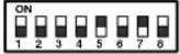 | 80 | 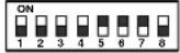 | 112 |
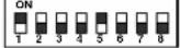 | 17 | 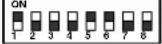 | 49 | 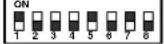 | 81 | 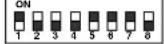 | 113 |
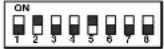 | 18 | 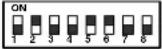 | 50 | 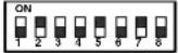 | 82 | 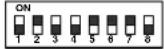 | 114 |
 | 19 | 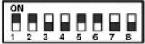 | 51 | 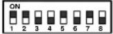 | 83 | 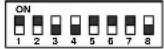 | 115 |
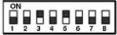 | 20 | 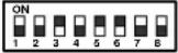 | 52 | 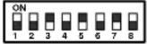 | 84 | 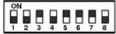 | 116 |
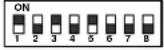 | 21 | 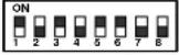 | 53 | 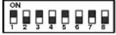 | 85 | 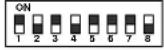 | 117 |
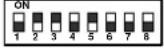 | 22 | 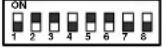 | 54 | 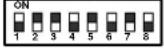 | 86 | 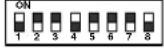 | 118 |
 | 23 | 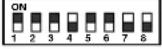 | 55 | 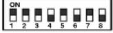 | 87 | 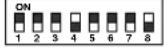 | 119 |
 | 24 | 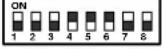 | 56 | 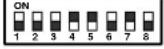 | 88 | 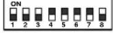 | 120 |
 | 25 | 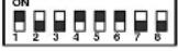 | 57 | 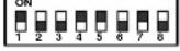 | 89 | 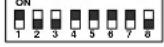 | 121 |
 | 26 | 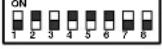 | 58 | 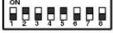 | 90 | 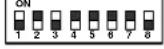 | 122 |
 | 27 | 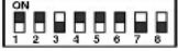 | 59 | 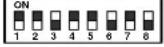 | 91 | 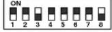 | 123 |
 | 28 | 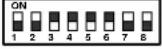 | 60 | 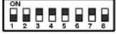 | 92 | 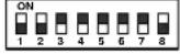 | 124 |
 | 29 | 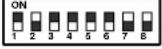 | 61 | 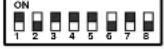 | 93 | 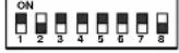 | 125 |
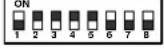 | 30 | 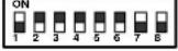 | 62 | 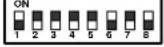 | 94 | 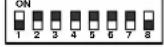 | 126 |
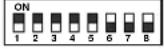 | 31 | 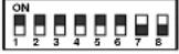 | 63 | 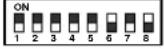 | 95 | 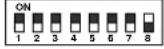 | 127 |
Switch Address
| ON1 2 3 4 5 6 7 8 | 128 |
| ON1 2 3 4 5 6 7 8 | 129 |
| ON1 2 3 4 5 6 7 8 | 130 |
| ON1 2 3 4 5 6 7 8 | 131 |
| ON1 2 3 4 5 6 7 8 | 132 |
| ON1 2 3 4 5 6 7 8 | 133 |
| ON1 2 3 4 5 6 7 8 | 134 |
| ON1 2 3 4 5 6 7 8 | 135 |
| ON1 2 3 4 5 6 7 8 | 136 |
| ON1 2 3 4 5 6 7 8 | 137 |
| ON1 2 3 4 5 6 7 8 | 138 |
| ON1 2 3 4 5 6 7 8 | 139 |
| ON1 2 3 4 5 6 7 8 | 140 |
| ON1 2 3 4 5 6 7 8 | 141 |
| ON1 2 3 4 5 6 7 8 | 142 |
| ON1 2 3 4 5 6 7 8 | 143 |
| ON1 2 3 4 5 6 7 8 | 144 |
| ON1 2 3 4 5 6 7 8 | 145 |
| ON1 2 3 4 5 6 7 8 | 146 |
| ON1 2 3 4 5 6 7 8 | 147 |
| ON1 2 3 4 5 6 7 8 | 148 |
| ON1 2 3 4 5 6 7 8 | 149 |
| ON1 2 3 4 5 6 7 8 | 150 |
| ON1 2 3 4 5 6 7 8 | 151 |
| ON1 2 3 4 5 6 7 8 | 152 |
| ON1 2 3 4 5 6 7 8 | 153 |
| ON1 2 3 4 5 6 7 8 | 154 |
| ON1 2 3 4 5 6 7 8 | 155 |
| ON1 2 3 4 5 6 7 8 | 156 |
| ON1 2 3 4 5 6 7 8 | 157 |
| ON1 2 3 4 5 6 7 8 | 158 |
| ON1 2 3 4 5 6 7 8 | 159 |
Switch Address
| ON1 2 3 4 5 6 7 8 | 160 |
| ON1 2 3 4 5 6 7 8 | 161 |
| ON1 2 3 4 5 6 7 8 | 162 |
| ON1 2 3 4 5 6 7 8 | 163 |
| ON1 2 3 4 5 6 7 8 | 164 |
| ON1 2 3 4 5 6 7 8 | 165 |
| ON1 2 3 4 5 6 7 8 | 166 |
| ON1 2 3 4 5 6 7 8 | 167 |
| ON1 2 3 4 5 6 7 8 | 168 |
| ON1 2 3 4 5 6 7 8 | 169 |
| ON1 2 3 4 5 6 7 8 | 170 |
| ON1 2 3 4 5 6 7 8 | 171 |
| ON1 2 3 4 5 6 7 8 | 172 |
| ON1 2 3 4 5 6 7 8 | 173 |
| ON1 2 3 4 5 6 7 8 | 174 |
| ON1 2 3 4 5 6 7 8 | 175 |
| ON1 2 3 4 5 6 7 8 | 176 |
| ON1 2 3 4 5 6 7 8 | 177 |
| ON1 2 3 4 5 6 7 8 | 178 |
| ON1 2 3 4 5 6 7 8 | 179 |
| ON1 2 3 4 5 6 7 8 | 180 |
| ON1 2 3 4 5 6 7 8 | 181 |
| ON1 2 3 4 5 6 7 8 | 182 |
| ON1 2 3 4 5 6 7 8 | 183 |
| ON1 2 3 4 5 6 7 8 | 184 |
| ON1 2 3 4 5 6 7 8 | 185 |
| ON1 2 3 4 5 6 7 8 | 186 |
| ON1 2 3 4 5 6 7 8 | 187 |
| ON1 2 3 4 5 6 7 8 | 188 |
| ON1 2 3 4 5 6 7 8 | 189 |
| ON1 2 3 4 5 6 7 8 | 190 |
| ON1 2 3 4 5 6 7 8 | 191 |
Switch Address
| ON1 2 3 4 5 6 7 8 | 192 |
| ON2 3 4 5 6 7 8 | 193 |
| ON1 2 3 4 5 6 7 8 | 194 |
| ON1 2 3 4 5 6 7 8 | 195 |
| ON1 2 3 4 5 6 7 8 | 196 |
| ON1 2 3 4 5 6 7 8 | 197 |
| ON1 2 3 4 5 6 7 8 | 198 |
| ON1 2 3 4 5 6 7 8 | 199 |
| ON1 2 3 4 5 6 7 8 | 200 |
| ON1 2 3 4 5 6 7 8 | 201 |
| ON1 2 3 4 5 6 7 8 | 202 |
| ON1 2 3 4 5 6 7 8 | 203 |
| ON1 2 3 4 5 6 7 8 | 204 |
| ON1 2 3 4 5 6 7 8 | 205 |
| ON1 2 3 4 5 6 7 8 | 206 |
| ON1 2 3 4 5 6 7 8 | 207 |
| ON1 2 3 4 5 6 7 8 | 208 |
| ON1 2 3 4 5 6 7 8 | 209 |
| ON1 2 3 4 5 6 7 8 | 210 |
| ON1 2 3 4 5 6 7 8 | 211 |
| ON1 2 3 4 5 6 7 8 | 212 |
| ON1 2 3 4 5 6 7 8 | 213 |
| ON1 2 3 4 5 6 7 8 | 214 |
| ON1 2 3 4 5 6 7 8 | 215 |
| ON1 2 3 4 5 6 7 8 | 216 |
| ON1 2 3 4 5 6 7 8 | 217 |
| ON1 2 3 4 5 6 7 8 | 218 |
| ON1 2 3 4 5 6 7 8 | 219 |
| ON1 2 3 4 5 6 7 8 | 220 |
| ON1 2 3 4 5 6 7 8 | 221 |
| ON1 2 3 4 5 6 7 8 | 222 |
| ON1 2 3 4 5 6 7 8 | 223 |
Switch Address
| ON1 2 3 4 5 6 7 8 | 224 |
| ON1 2 3 4 5 6 7 8 | 225 |
| ON1 2 3 4 5 6 7 8 | 226 |
| ON1 2 3 4 5 6 7 8 | 227 |
| ON1 2 3 4 5 6 7 8 | 228 |
| ON1 2 3 4 5 6 7 8 | 229 |
| ON1 2 3 4 5 6 7 8 | 230 |
| ON1 2 3 4 5 6 7 8 | 231 |
| ON1 2 3 4 5 6 7 8 | 232 |
| ON1 2 3 4 5 6 7 8 | 233 |
| ON1 2 3 4 5 6 7 8 | 234 |
| ON1 2 3 4 5 6 7 8 | 235 |
| ON1 2 3 4 5 6 7 8 | 236 |
| ON1 2 3 4 5 6 7 8 | 237 |
| ON1 2 3 4 5 6 7 8 | 238 |
| ON1 2 3 4 5 6 7 8 | 239 |
| ON1 2 3 4 5 6 7 8 | 240 |
| ON1 2 3 4 5 6 7 8 | 241 |
| ON1 2 3 4 5 6 7 8 | 242 |
| ON1 2 3 4 5 6 7 8 | 243 |
| ON1 2 3 4 5 6 7 8 | 244 |
| ON1 2 3 4 5 6 7 8 | 245 |
| ON1 2 3 4 5 6 7 8 | 246 |
| ON1 2 3 4 5 6 7 8 | 247 |
| ON1 2 3 4 5 6 7 8 | 248 |
| ON1 2 3 4 5 6 7 8 | 249 |
| ON1 2 3 4 5 6 7 8 | 250 |
| ON1 2 3 4 5 6 7 8 | 251 |
| ON1 2 3 4 5 6 7 8 | 252 |
| ON1 2 3 4 5 6 7 8 | 253 |
| ON1 2 3 4 5 6 7 8 | 254 |
| ON1 2 3 4 5 6 7 8 | 255 |
2.3.2. Communication Protocol Setting
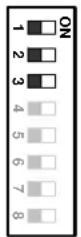
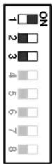
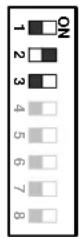
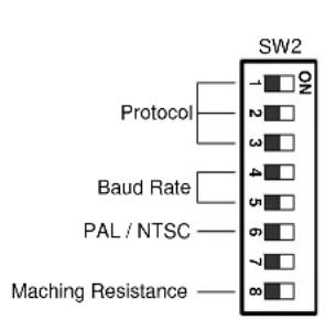
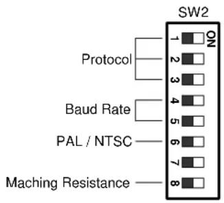
The 1^st , 2^nd and 3^rd bits of the SW2 are used to set communication protocol. The factory default protocol is EVF.
EVF - 1
PELCO-D
PELCO-P
TYPE-A
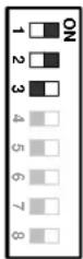
Notice: Please make sure the power is off before setting, and restart the speed dome to enable a new value after changing.
Set all of protocol switches to ON; the EPTZ900/500 will enter a self-test mode.
2.3.3. Transmission Speed Setting (Baud Rate Setting)
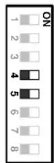
The 4^th and 5^th bits of the SW2 on the PCB board are used to set the Baud Rate. The default baud rate setting is 9600.
9600 BPS 4800 BPS 2400 BPS
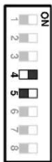
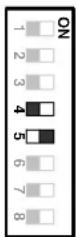
1200 BPS
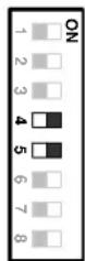
Notice: Please make sure the power is off before setting, and restart the speed dome to enable a new value after changing.
2.3.4. Video Format Setting
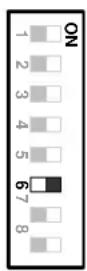
The 6^th bits of the SW2 on the PCB board are used to set the video format. The default video format depends on the factory setting. Please do not change it.
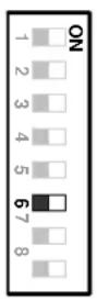
PALNTSC
Notice: Please make sure the power is off before setting, and restart the speed dome to enable a new value after changing.
2.3.5. RS-485 Bus Terminator Resistance
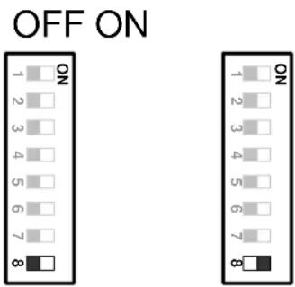
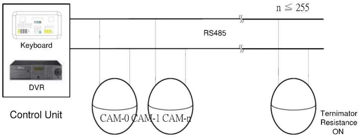
For central controlling, the terminator resistance should be set for the device that is the furthest one away from the controller. The 8^th bit on the SW2 is a switch to enable or disable the terminator resistance. When it is switched ON, the BUS terminator resistance is connected.
flowchart
graph TD
    A["Control Unit"] --> B["Keyboard"]
    A --> C["DVR"]
    B --> D["RS485"]
    C --> D
    D --> E["Ternimator Resistance ON"]
    style A fill:#f9f,stroke:#333
    style B fill:#ccf,stroke:#333
    style C fill:#ccf,stroke:#333
    style D fill:#cfc,stroke:#333
    style E fill:#fcc,stroke:#333
Note: When the dome is out of control, or does not work under control well, try to switch the terminator resistance ON.
Notice: Please make sure the power is off before setting, and restart the speed dome to enable a new value after changing.
2.4. Rack and Speed Dome Installation
2.4.1. Installation Requirements
- Installation should be handled by a qualified service agent and should comply with all local regulations. Service personnel should expect potential problems such as surface strength, surface material, falling objects, outer breaches, building vibration or other similar conditions.
- Check for all necessary materials, and ensure if the selected installation location is suitable for the speed dome.
2.4.2. EPTZ900 Dome Camera Wall Mount Installation
Notice: Installation location that is a wall, a pole or a ceiling needs to support above five times the total weight of the camera assembly (about 16 kg) to avoid shaken images, and dropping.
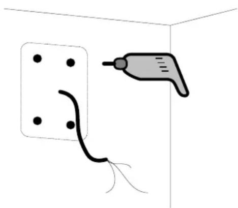
- Set wall mount bracket on the wall. Mark the center of the holes on the wall against the bracket holes. Use a drill to make 4 holes that can be nailed 4 0.25" X 1.25" screws at the marks.
natural_image
Simple line drawing of a tool inserting into a wall socket (no text or symbols)Notice: The length of the screws depends on the surface material. The mentioned screws are used in the normal concrete surface.
- Thread the cable through the hole in the wall mount bracket, and screw in 4 M8 nuts for mounting the bracket.
- Take off the housing from the packing, and take off the baseboard (4 bolts on it.) inside the housing. Thread the cable through the top of the housing. Fix the housing on the wall mount bracket, and screw in 3 M5 bolts (Hex) on the top of the bracket with the attached Hex Allen wrench to fix the housing.
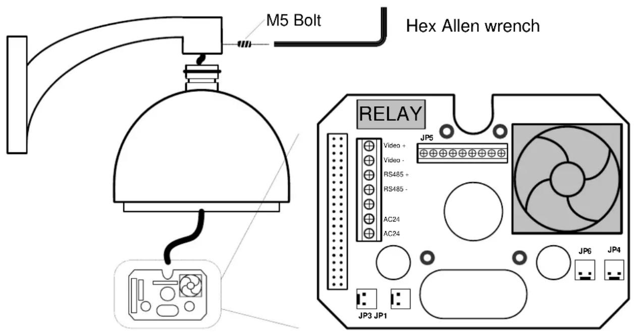
- Connect the cable connectors to the nodes on the baseboard, and then fix the baseboard in the housing by screwing 4 bolts on it.
Notice: Please notice the polarity of control line. The EPTZ900 will not work if the polarity of control line is mis-connected.
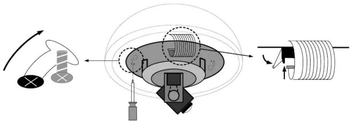
- Align the two screw holes on the bottom of mechanical part to the two bolts on the base of the housing, and twist the mechanical part clockwise a little bit in order to engage it with the base. Screw the two bolts on the base, and then connect and fix the connection bus to the PCB board on the mechanical part.
flowchart
graph TD
    A["Motor"] --> B["Cool"]
    B --> C["Battery"]
    C --> D["Capacitor"]
    D --> E["Coiled Coil"]
    style A fill:#f9f,stroke:#333
    style B fill:#ccf,stroke:#333
    style C fill:#cfc,stroke:#333
    style D fill:#fcc,stroke:#333
    style E fill:#ffc,stroke:#333
Notice: The camera module on the mechanical part is very sensitive. Please be careful when installing this part.
- Remove the lens protection cover before installing the bulb. Align the 3 bolt holes into the 3 housing bolt holes, and screw thee M3 bolts with the attached small screw driver to fix the bulb.
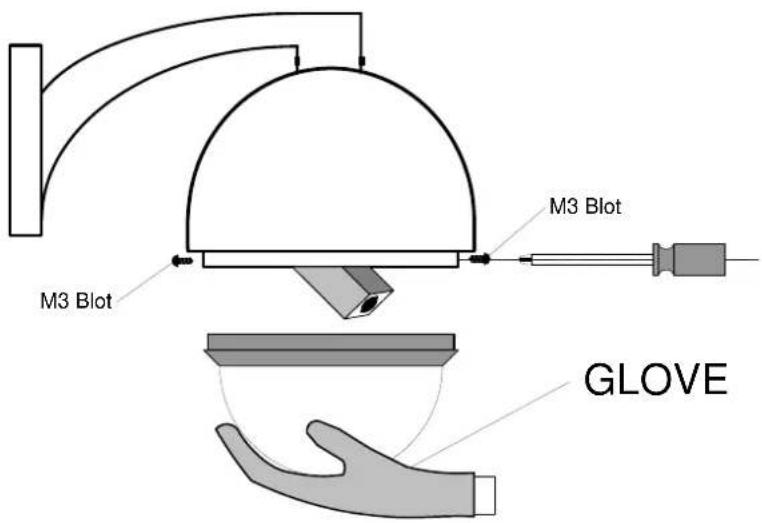
Notice: In order to protect the bulb from dirt and scrape, please put on the gloves before installing the bulb.
- Turn on the power, and start to operate the EPTZ900.
Note: When turning on the power, the EPTZ900 will enter self-inspection mode, and carry out a self-testing program. After finishing self-inspection, you can start to operate the EPTZ900.
2.4.3. EPTZ500 Dome Camera Installation
- Take off the housing from the packing, and take off the PCB board (4 bolts on it) inside the housing.
- Cut the ceiling against the housing's shape with a saw.
- Thread the cable through the screw and the hole on the top of the housing, and tighten up the screw to fix the cable
- Place the housing into the hole that you just made. Fix the housing on the ceiling with two clips, adjust the screws of clips to make the housing perfectly fit to the ceiling.
- Connect the cable connectors to the nodes on the base board, and then fix the base board in the housing by screwing 4 bolts on it.
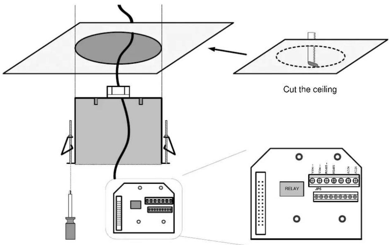
Notice: Please notice the polarity of control line. The EPTZ500 will not work if the polarity of control line is mis-connected.
- Align the two screw holes on the bottom of mechanical part to the two bolts on the base of the housing, and twist the mechanical part clockwise a little bit in order to engage it with the base. Screw the two bolts on the base, and then connect and fix the connection bus to the PCB board on the mechanical part.
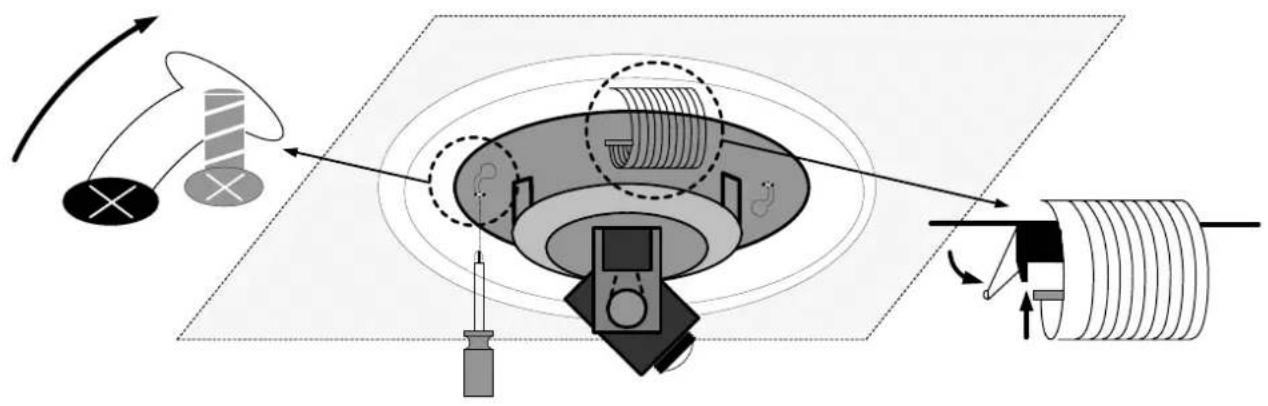
flowchart
graph TD
    A["Central Device"] --> B["Rotating Component"]
    B --> C["Circulating Coil"]
    style A fill:#f9f,stroke:#333
    style C fill:#bbf,stroke:#333
Notice: The camera module on the mechanical part is very sensitive. Please be careful when installing this part.
- Remove the lens protection cover before installing the bulb. Screw the connection wire to the housing in order to prevent the bulb from being drop down. Align the 2 buttons on the bulb base with the 2 buttons on the housing, and push bulb base to clip the housing.
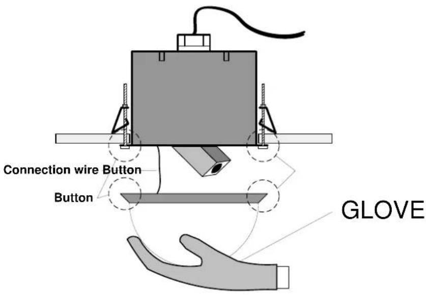
Notice: In order to protect the bulb from dirt and scrape, please put on the gloves before installing the bulb.
- Turn on the power, and start to operate the EPTZ500.
2.5. Separately Sold Accessories
2.5.1. Pole mount
natural_image
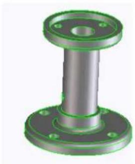
3D rendered image of a mechanical flange component with green and gray sections (no text or symbols)The pole mount is used for installing a speed dome on the ceiling indoors or outdoors.
The extension poles are available for the pole mount.
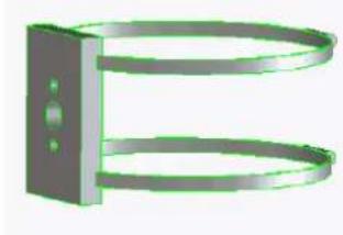
2.5.2. Pole adapter
natural_image
3D rendering of a metallic mechanical clamp or bracket with two circular ends and a central vertical bar (no text or symbols)The pole adapter is used for installing a wall mount bracket to a pole indoors or outdoors.
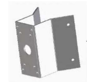
2.5.3. Corner mount
natural_image
3D rendering of a rectangular metal bracket with mounting holes and a central hole (no text or symbols)The corner mounts are used for installing a wall mount bracket to a 270^ corner of walls indoors or outdoors.
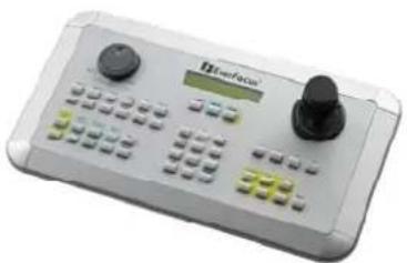
2.5.4. Multi-Function Keyboard Controller
natural_image
Front view of a medical or laboratory device with control buttons and a display (no visible text or symbols)Multi-Function System Controller
Capable of controlling PTZ, DVR and Monitor
3D Joystick control of PTZ function
3. EPTZ900/500 CAMERA SETUP MENU
In this section, setup and operation guide of EPTZ900/500 will be introduced. There are 22 items of the setting menu. However, there is only one line on the line display, so using some combination keys to operate is necessary.
3.1. Structure of the Setup Menu
Press MENU to enter camera setup menu.
Press Shift + Joystick up/down to change subentries, and right/left to change the setting.
OptionItems
| CAM ID | ---- |
| DZOOM | OFF / ON |
| FOCUS | AUTO / MAN / ONE PUSH |
| NEGATIVE | OFF / ON |
| COLOR | OFF / ON |
| DISPLAY | OFF / ON |
| BACKLIGHT | OFF / ON |
| WBC MODE | AUTO / INDOOR / OUTDOOR / MAN |
| TITLE DISPLAY | OFF / ON |
| AUTO FLIP | OFF / ON |
| ALM-IN1 SET | N.O. / N.C. / OFF |
| ALM-IN2 SET | N.O. / N.C. / OFF |
| ALM-IN3 SET | N.O. / N.C. / OFF |
| ALM-IN4 SET | N.O. / N.C. / OFF |
| ALM-IN PRIO | 1234 / 2341 / 3421 / 4123 |
| OFF / ONALM-OUT | |
| LOAD DEFAULT | ---- |
| EXIT MENU | ---- |
3.1.1. Camera Setup Menu
Press MENU to enter camera setup menu.
Press Shift + Joystick up/down to change subentries, and right/left to change the setting.
- CAM ID : The name assigned to the camera.
- DZOOM : Digital zoom enable or disable.
ON: Enable a digital zoom.
OFF: Disable a digital zoom.
- FOCUS : Focus type, auto focus and manual focus are available.
AUTO: Auto focus is enabled.
MAN: Manual focus is enabled.
ONE PUSH: Enable the one push trigger focus mode. The focus lens holds the same position until the next trigger command is received. This function prevents the wrong focus in dark.
- NEGATIVE : Negative image.
ON: Enable a negative image.
OFF: Disable a negative image.
- COLOR : Color display.
ON: Enable a color display.
OFF: Disable a color display, and show a B&W display.
- DISPLAY : Display system information and status.
ON: To display the system information and status on the screen.
OFF: Not to display the system information and status on the screen.
- BACKLIGHT : Backlight compensation.
ON: Enable backlight compensation.
OFF: Disable backlight compensation.
- WBC MODE : White balance mode.
AUTO: Auto white balance mode.
INDOOR: Indoor white balance mode.
OUTDOOR: Outdoor white balance mode.
MAN: Manual white balance mode.
- TITLE DISPLAY : Display the title.
ON: Enable title display.
OFF: Disable title display.
- AUTO FLIP : Flip the camera when it tilts to the 90° end.
ON: Enable auto flip.
OFF: Disable auto flip.
- ALM-IN1 SET : The status of input alarm 1.
N.O.: Enable a normal open alarm input.
N.C.: Enable a normal close alarm input.
OFF: Disable alarm input.
- ALM-IN2 SET : The status of input alarm 2.
N.O.: Enable a normal open alarm input.
N.C.: Enable a normal close alarm input.
OFF: Disable alarm input.
- ALM-IN3 SET : The status of input alarm 3.
N.O.: Enable a normal open alarm input.
N.C.: Enable a normal close alarm input.
OFF: Disable alarm input.
- ALM-IN4 SET : The status of input alarm 4.
N.O.: Enable a normal open alarm input.
N.C.: Enable a normal close alarm input.
OFF: Disable alarm input.
- ALM-IN PRIO : The priority of alarms.
1234: The alarm priority is 1>2>3>4.
2341: The alarm priority is 2>3>4>1.
3412: The alarm priority is 3>4>1>2.
4123: The alarm priority is 4>1>2>3.
- ALM-OUT : Alarm output. There is a built-in relay to offer an alarm output.
ON: Enable alarm output.
OFF: Disable alarm output.
- LOAD DEFAULT : Load default setting.
Select this item, and then press "Enter" to load default setting.
Press “Clr” + “Menu” whenever you want to quit menu setting.
- EXIT : To exit
Select this item, and then press "Enter" to quit setting.
Press “Clr” + “Menu” whenever you want to quit menu setting.
4. EPTZ900/500 FUNCTION SETUP AND OPERATION
4.1. Manual Control Mode
Manual control: Shift Joystick Up/Down/Left/Right, and turn it
Clockwise/Counterclockwise to control speed dome.
Use the control keys which are Zoom, Focus and IRIS function keys on the keyboard to zoom In/Out, focus N (near)/F (Far), or IRIS +/-
HOME Mode: The camera view will go back to the home position when there is no keyboard operation in a specific time. The home position and the specific time can be set by press Set + Home.
4.2. Auto Pan Mode
Two point auto pan: Press A.Pan to enter the auto pan mode, and then the system will ask you to enter the auto pan speed (1\~239). Press Enter to start auto pan. In order to set the two points, press Set + A.Pan, and then enter the dwell time (1\~239 seconds) of each point.
360° auto pan: Press Shift + A.Pan to enter the 360° auto pan. The camera will turn 360° automatically, but not tilt.
4.3. Position Setting
Focus on a preset position: Press the number key, and then press Position to focus on the number of preset position; or you can press Position, then enter the preset position number, and then press Enter to focus on the number of preset position.
➢ Preset a position: Shift the Joystick to the position you would like to preset, and then press Shift + Position. The system will ask you to enter the preset position number (1\~239), and then press Enter to save the position. There are up to 192 positions can be preset.
Set the parameter of a preset position: Press Set + Position to set the parameter of a preset position. You can set the going-to speed (1\~239), dwell time (1\~239 seconds), and the title of the position. Shift the joystick Right/Left to change bits, and shift the Joystick Up/Down to change the alphanumeric characteristic. The available alphanumeric characteristics are 0\~9, A\~Z, &, ?, !, :, ', ,, , /, -, and a space.
Delete a preset position: Press Clr + Position to delete a preset position. The system will ask you to enter the position number that you would like to delete, and then press Enter.
4.4. Tour Mode
In the tour mode, you can set a tour for viewing. There are 16 tours can be set, and 16 preset positions in a tour.
One-way tour Mode: Press Tour to enter the tour mode. The system will ask you to enter the tour number you would like to run, and starts the tour after pressing Enter. To preset a tour before running it is necessary.
Preset a one-way tour: Press Set + Tour to preset a one-way tour. The system will ask you to enter preset position numbers (The positions need to be preset). After finish entering all positions, press Stop to quit, and then press Enter to save the tour.
To-and-fro tour mode: Press Shift + Tour to run a to-and-fro tour. The system will
ask you to enter the tour number you would like to run, and starts the tour after pressing Enter. To preset a tour before running it is necessary.
Note: The difference between the One-way tour mode and To-and-fro tour mode is their return modes. For example: There is a tour with 3 preset positions 1, 2 and 3. The camera runs 1 2 3 1 2 3 in the One-way tour mode, and 1 2 3 2 1 in the To-and-fro tour mode.
4.5. Alarm Link to a Position/Tour
The EPTZ900/500 has 4 alarm inputs that can be set to link to a position or a tour when an alarm is triggered.
Set an alarm link:
Press F1 to set an alarm link. Enter the alarm number, and then press Enter.
Switch the Joystick up/down to select a position or a tour, enter a position or tour number, and then press Enter to confirm the alarm link setting.
➢ Delete an alarm link:
Press +1 to delete a link of alarm to position/tour.
4.6. Other operations
The EPTZ900/500 can work with a DVR that has PTZ control functions, and a matching protocol. The available control functions depend on different DVRs.
The EPTZ900/500 can work with a keyboard that has PTZ control functions, and a matching protocol. The available control functions depend on different keyboards.
APPENDIX A: The Alarm I/O Connection
There are 4 alarm inputs and 1 alarm output available. The alarm I/O connector that is marked as JP5 is a nine-pin connector. It is located on the PCB board of the housing.
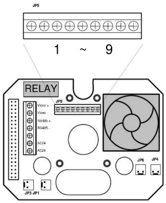
EPTZ900 base board
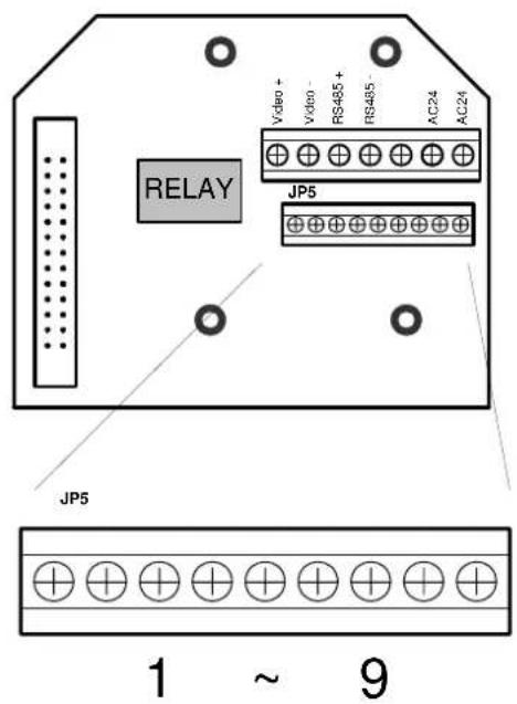
EPTZ500 base board
| Pin # Function | |
| 1 Alarm Input 4 | |
| 2 | Ground |
| 3 Alarm Input 3 | |
| 4 Alarm Input 2 | |
| 5 | Ground |
| 6 Alarm Input 1 | |
| 7 Normal Open (N.O.) | |
| 8 | Common |
| 9 Normal Close (N.C.) | |
Speed Dome Control Protocol
1-1. Format
A. Fixed 7 bytes packet
Byte1 (cmd1 = 0xFA)
Byte2 (cmd2)
Byte3 (ID high byte)
Byte4 (ID low byte)
Byte5 (data1)
Byte6 (Kcyboard-ID)
Byte7 (checksum)
B. Fixed 8 bytes packet
Byte1 (cmd1 = 0xFC)
Byte2 (cmd2)
Byte3 (ID high byte)
Byte4 (ID low byte)
Byte5 (data1)
Byte6 (Keyboard-ID)
Byte7 (data2)
Byte8 (checksum)
1-2. checksum calculation
- Address = IDH*32 + IDL
- Movement Speed: 01-EI => begin speed value (01:Slow, EI:Fast)
- checksum => B7=(B1+B2+B3+B4+B5+B6)&0x7f
00 => stop
| FUNCTION | (B1) | (B2) | (B3) | (B4) | (B5) | (B6) | (B7) | |
| CMD1 | CMD2 | IDH | IDL | DATA1 | KB-ID | CSUM | DESCRIPTION | |
| Up | FA | 01 | 00-1F | 00-1F | speed | 00-5F | cs | speed=00-EFh |
| Down | FA | 02 | . | . | speed | . | cs | |
| Left | FA | 03 | . | . | speed | . | cs | |
| Right | FA | 04 | . | . | speed | . | cs | |
| Left-up | FA | 05 | . | . | speed | . | cs | |
| Left-down | FA | 06 | . | . | speed | . | cs | |
| Broadcast | FA | 09-0E | 20 | 00 | grade | . | cs | |
| Location A | FA | 0F | . | . | WaitT | . | cs | WaitT=0-EFh (second) |
| Location B | FA | 13 | . | . | WaitT | . | cs | |
| Line Scanning Startup | FA | 10 | . | . | speed | . | cs | speed =01-EFh |
| Right-up | FA | 07 | . | . | speed | . | cs | |
| Right-down | FA | 08 | . | . | speed | . | cs | |
| Broadcast | FA | 01-08 | 20 | 00 | speed | . | cs | |
| Iris Open | FA | 09 | . | . | grade | . | cs | grade=00-EFh |
| Iris Close | FA | 0A | . | . | grade | . | cs | |
| Zoom Tele | FA | 0B | . | . | grade | . | cs | |
| Zoom Wide | FA | 0C | . | . | grade | . | cs | |
| Focus Far | FA | 0D | . | . | grade | . | cs | |
| Focus Near | FA | 0E | . | . | grade | . | cs | |
| Surface scan Startup | FA | 11 | . | . | speed | . | cs | |
| startup cruise group | FA | 71 | . | . | group | . | cs | group=1-16 |
| startup intercruiseScan | FA | 72 | . | . | group | . | cs | |
| Set Preset pos | FA | 75 | . | . | pp | . | cs | pp=1-192 (position) |
| To Preset pos | FA | 76 | . | . | pp | . | cs | |
| cruise set start | FA | 77 | . | . | group | . | cs | group=1-16 |
| adding cruise point | FA | 78 | . | . | pp | . | cs | pp=1-192 (position) |
| cruise set close | FA | 79 | . | . | AA | . | cs | |
| Set Single Point Alarm Linkage | FA | 7A-7D | . | . | pp | . | cs | | pp=1-192 (position) |
| Clr Single Point Alarm Linkage | FA | 7E-81 | . | . | AA | . | cs | | |
| Cruise Alarm Linkage Set | | FA | 82-85 | . | . | group | . | cs | | group=1-16 |
| Cruise Alarm Linkage Cancel | | FA | 86-89 | . | . | AA | . | cs | | |
| set preset position parameter | | FA | A0 | . | . | pp | . | cs | | pp=1-192 (position) |
| speed to preset position | | FA | A1 | . | . | speed | . | cs | | speed=1-EFh |
| Dwell time at preset position | | FA | A2 | . | . | dwell | . | cs | | dwell=1-EFh (seconds) |
| Set PresetPosition Param Closel | FA | A3 | . | . | AA | . | cs | | |
| Home Position Set | | FA | A4 | . | . | AA | . | cs | | |
| Wait time at Home Position | | FA | A5 | . | . | WaitT | . | cs | | WaitT=0-EFh (minutes) |
| Enable Home position On/Close | | FA | A6 | . | . | on-off | . | cs | | on-off=0/1 (0=off, 1=on) |
| Clear Preset Position | | FA | A7 | . | . | pp | . | cs | | pp=1-192 (position) |
| Speed Dome Setup Menu | | FA | 90 | . | . | operate | . | cs | | operate=01 Enter menu mode |
| | | | =02 Exit menu mode | |||||||
| | | | =03 menu cursor up | |||||||
| | | | =04 mcnu cursor down | |||||||
| | | | =05 menu cursor left | |||||||
| | | | =06 menu cursor right | |||||||
| | | | =07 select option | |||||||
| | | | =08 confirm |
2-2. Part-11 (Enhance part)
| | (B1) | (B2) | (B3) | (B4) | (B5) | (B6) | (B7) | (B8) | | | |
| FUNCTION | | CMD1 | CMD2 | ID11 | IDL | DATA1 | KB-ID | DATA2 | CSUM | DESCRIPTION |
| enhance move | +---- | ---- | ---- | ---- | ---- | ---- | ---- | ---- | +---- |
| | FC | OP | . | . | x-spd | . | y-spd | cs | | OP: (0-3) | |
| | | | bit0: (0=right, l=left) | ||||||||
| | | | bit1: (0=up, l=down) | ||||||||
| | | | | ||||||||
| | | | x-spd=0-EFh | ||||||||
| | | | y-spd=0-EFh | ||||||||
| set preset position title | | FC | 05 | . | . | x-coor | . | char | cs | | x-coor=0-19 |
| | | | char=ASCII code | ||||||||
| | | | notice: | ||||||||
| | | | make sure you already send | ||||||||
| | | | "FA A0" command, before send | ||||||||
| | | | this command. | ||||||||
| | | | | ||||||||
| clean preset position title | | FC | OA | . | . | PP | . | 00 | cs | | PP=1-192 |
| Remote reboot | | FC | OC | . | . | 55 | . | AA | 08 | | |
| | | | |
EverFocus Electronics Corp.
Head Office:
12F, No.79 Sec. 1 Shin-Tai Wu Road,
Hsi-Chih, Taipei, Taiwan
TEL: +886-2-26982334
FAX: +886-2-26982380
www.everfocus.com.tw
China Office:
Room 609, Technology Trade Building,
Shandgdi Information Industry Base,
Haidian District, Beijing, China
TEL: +86-10-62971096
FAX: +86-10-62971432
www.everfocus.com.cn
USA Office:
1801 Highland Ave. Unit A
Duarte, CA 91010, U.S.A.
TEL: +1-626-844-8888
FAX: +1-626-844-8838
www.everfocus.com
Japan Office:
1809 WBG MARIBU East 18F,
2-6 Nakase.Mihama-ku.
Chiba city 261-7118, Japan
D-46446 Emmerich, Germany
TEL: 49-2822-9394-0
FAX: 49-2822939495
www.everfocus.de

- Table of Contents
- EPTZ900/500 OVERVIEW....1-3
- EPTZ900/500 INSTALLATION 2-12
- Separately Sold Accessories....2-27
- EPTZ900/500 CAMERA SETUP MENU....3-28
- Structure of the Setup Menu 3-28
- EPTZ900/500 FUNCTION SETUP AND OPERATION...4-33
- APPENDIX B: Protocol 4-37
- EPTZ900/500 OVERVIEW
- Introduction
- Feature
- Profile of EPTZ900/500
- Base Board
- EPTZ900/500 Control Board
- EPTZ900/500 Connection
- EPTZ900/500 Quick Operation Guide (Work with EKB500)
- To operate the EPTZ900/500:
- EPTZ900/500 INSTALLATION
- Packing List
- Cable Needed
- - Power Cable
- - Video Cable
- - Control Cable
- - Alarm Cable
- Initial Setup
- Address Setting
- Communication Protocol Setting
- Transmission Speed Setting (Baud Rate Setting)
- Video Format Setting
- RS-485 Bus Terminator Resistance
- Rack and Speed Dome Installation
- Installation Requirements
- EPTZ900 Dome Camera Wall Mount Installation
- EPTZ500 Dome Camera Installation
- Separately Sold Accessories
- Pole mount
- Pole adapter
- Corner mount
- Multi-Function Keyboard Controller
- EPTZ900/500 CAMERA SETUP MENU
- Structure of the Setup Menu
- Camera Setup Menu
- EPTZ900/500 FUNCTION SETUP AND OPERATION
- Manual Control Mode
- Auto Pan Mode
- Position Setting
- Tour Mode
- Alarm Link to a Position/Tour
- Set an alarm link:
- ➢ Delete an alarm link:
- Other operations
- APPENDIX A: The Alarm I/O Connection
- 1-1. Format
- 1-2. checksum calculation
- EverFocus Electronics Corp.
- Head Office:
- China Office:
- USA Office:
- Japan Office:
Brand : EverFocus
Model : EPTZ500
Category : Security Camera