EDH5240 - Security Camera EverFocus - Free user manual and instructions
Find the device manual for free EDH5240 EverFocus in PDF.


| Product Type | 2 Megapixel Full HDcctv Indoor IR Dome Camera |
| Brand | EverFocus |
| Model | EDH5240 |
| Image Sensor | 1/2.7" 2 megapixel progressive scan CMOS |
| Resolution | 1920x1080 (1080p) or 1280x720 (720p) |
| Lens | Vari-focal 3.3~12mm, F1.4, auto iris |
| IR Distance | Up to 20m / 65 feet |
| IR LEDs | 34 high output LEDs, 850nm, lifespan 20,000 hours |
| Video Output | HDcctv (BNC), test output (BNC) |
| Power Source | 12VDC / 24VAC auto polarity detect |
| Power Consumption | 24VAC: 7.2W IR off, 11.3W max; 12VDC: 4.7W IR off, 7.4W max |
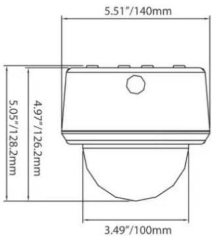
| Dimensions (Surface Mount) | 140mm x 128mm (5.5" x 5.1") |
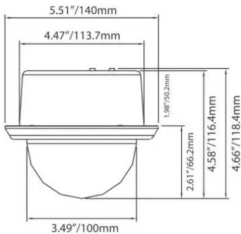
| Dimensions (Flush Mount) | 140mm x 68mm (5.5" x 2.8") |
| Weight | 660g / 1.45 lbs |
| Operating Temperature | 0°C to 40°C (32°F to 104°F) |
| Mounting Options | Surface mount or flush mount (in-ceiling) |
| Day/Night | True day/night with automatic ICR removal |
| OSD Menu | Yes, via 5-axis joystick |
| Back Light Compensation | On/Off selectable |
| Auto Gain Control | High/Middle/Low/Off selectable |
| White Balance | AWB, One Push WB, Manual, Indoor, Outdoor |
| Package Contents | Camera unit, manual, accessory pack (screws, anchors, hex key, etc.), mounting template |
| Cleaning | Use damp soft cloth for body; lens tissue and ethanol for lens |
Frequently Asked Questions - EDH5240 EverFocus
User questions about EDH5240 EverFocus
0 question about this device. Answer the ones you know or ask your own.
Ask a new question about this device
Download the instructions for your Security Camera in PDF format for free! Find your manual EDH5240 - EverFocus and take your electronic device back in hand. On this page are published all the documents necessary for the use of your device. EDH5240 by EverFocus.
USER MANUAL EDH5240 EverFocus
natural_image
Exterior view of a surveillance camera (no visible text or symbols on body)EverFocus®
2 Megapixel Full HDcctv Indoor IR Dome Camera
Operation Instructions
Model No. EDH5240
Please read this manual first for correct installation and operation. This manual should be retained for future reference. The information in this manual was current when published. The manufacturer reserves the right to revise and improve its products. All specifications are therefore subject to change without notice.
PRECAUTIONS
- Do not install the camera near electric or magnetic fields.
Install the camera away from TV/radio transmitters, magnets, electric motors, transformers and audio speakers since the electromagnetic fields generated from these devices may distort the video image.
- Never disassemble the camera beyond the recommendations in this manual nor introduce materials other than those recommended herein.
Improper disassembly or introduction of corrosive materials may result in equipment failure or other damage.
- Try and avoid facing the camera toward the sun.
In some circumstances, direct sunlight may cause permanent damage to the sensor and/or internal circuits.
- Keep the power cord away from water and other liquids and never touch the power cord with wet hands.
Touching a wet power cord with hands or touching the power cord with wet hands may result in electric shock.
- Never install the camera in areas exposed to water, oil or gas.
Water, oil or gas may result in equipment failure, electric shock or, in extreme cases, fire.
- Cleaning
Do not touch the surface of the sensor directly with the hands. Use a damp soft cloth to remove any dirt from the camera body. Use lens tissue or a cotton tipped applicator and ethanol to clean the sensor and the camera lens. Please do not use complex solvents, corrosive or abrasive agents for cleaning.
- Do not operate the camera beyond the specified temperature, humidity or power source ratings.
Use the camera at temperatures within 0☐ \~ 40☐ (32 °F\~104°F) and humidity between 20\~80%. The input power source is 12VDC/24VAC.
TABLE OF CONTENTS
- PRODUCT OVERVIEW....2
1.1 Main Features 2
1.2 Package Contents.... 2
1.3 Specifications....3
1.4 Dimensions .... 4 - MAJOR PARTS: NAMES AND FUNCTIONS .... 4
- 3-AXIS GIMBAL BRACKET ....7
- INSTALLATION 8
- OSD Menu & Configuration.... 15
4.1 Exposure ...... 17
4.1.1 Lens 17
4.1.2 Shutter 18
4.1.3 AGC (Auto Gain Control - basic low light signal amplification) 18
4.1.4 BLC 18
4.1.5 Anti-Flicker 18
4.2 White Balance Control.... 18
4.3 Day/Night 19
4.4 Special....19
4.4.1 Resolution 19
4.4.2 Camera Title 19
4.4.3 D-Effect....20
4.4.4 TV standard....20
4.4.5 Language 20
4.4.6 Default 21
4.5 Image Adjust 21
4.5.1 Sharpness....21
4.5.2 Brightness 21
4.5.3 Contrast....21
1. PRODUCT OVERVIEW
The EDH5240 is an HDcctv 3-axis indoor dome camera with true Day/Night capability plus IR illumination, in a housing which can be surface or flush mounted. Based on a 2 megapixel progressive scan sensor for your choice of 1080 or 720 resolution HD 100% digital images, it delivers vastly superior video quality compared to traditional CCTV images. This superior resolution not only captures more critical evidentiary information, but the inherent ability for megapixel video to zoom with clarity to 4X or more improves and extends the area of coverage, expedites completion of investigations, resolves complaints and reduces both capital and operational costs.
No major upgrade to the IT network is required to deploy this powerful technology; HDcctv cameras communicate at digital speeds up to 1.5Gb/s over existing or new coaxial cable (RG59 or other types for longer distances), using industry standard BNC connectors. With a vari-focal 3.3\~10mm megapixel auto iris lens, combined with high output IR LEDs to produce detailed images under low or no light conditions out to a range of 20m/65 feet or more, the EDH5240 easily accommodates a wide range of indoor applications while delivering stunning image quality.
1.1 Main Features
● HDcctv 2 Megapixel real time 1920x1080 (or 1280x720) HD video over coax
● 2 megapixel progressive scan CMOS sensor
● Supports video outputs of 1080i, 1080p and 720p (field select)
● True day/night operation with automatic ICR module
● 3-axis positioning for flexible mounting and aiming
● 3.3\~10mm AI VF megapixel lens captures the desired field of view
● Field select choice of wall or ceiling, surface or flush mounting
● Easy to use OSD setup menu
● Dual Video Outputs: Megapixel HDcctv (BNC)
● SD TV Out (BNC) for aim and focus using a standard hand held test monitor
● Dual Power Source 12VDC/24VAC dual voltage auto polarity detect
● IR distance up to 65 feet/20m or more; High output IR LEDs, lifespan of 20,000 hours
1.2 Package Contents

Please be careful when you unpack the box and the electronic devices inside. Check and make sure that you have all the items listed below inside the original box:
- Camera Unit x 1, including dome/cover, camera unit and outer (surface mount) base as an assembly
● This Operation Manual x 1
Accessory pack #1 containing:
● 4 long mounting screws
- 4 washers
- 4 plastic anchors
● Hex key for cover screws
● 4 short screws to attach flush-mounting clips
● Rubber plug for side hole in outer base.
- Mounting template
● Power supply pigtail
- Video test cable
Accessory pack #2 containing two flush mounting clips
Please Note: If an item appears to have been damaged in shipment, replace it properly in its carton and notify the shipper. If any items are missing, notify your EverFocus Electronics Corp. Sales Representative or Customer Service. The shipping carton is the safest container in which the unit may be transported. Save it for possible future use.
1.3 Specifications
| Pickup Device 1/2.7" 2 megapixel CMOS sensorImage area for FOV 1080 mode: 6.61 mm diagonal; 5.76 mm H x 3.24 mm VImage area for FOV 720 mode: 4.41 mm diagonal; 3.84 mm H x 2.16 mm V | |
| Sensitivity 0.5lux/F=1.4 ; 0 lux IR ON | |
| S/N Ratio 45dB | |
| Video Format Main Output HDcctv | |
| Resolution Main Output 1920x1080 or 1280x720 | |
| Video Mode Main Output Field select 1080i60, 1080p30 or 720p60 for 60Hz systems1080i50, 1080p25 or 720p50 for 50Hz systems | |
| Main Output Connector BNC-F | |
| Video Format Test Output | NTSC/PAL selectable 1V p-p |
| Test Output Connector | Pin header; adapter cable to BNC-F supplied |
| Electronic Shutter Auto, 1/60(1/50)~1/8000 | |
| Lens Type | Megapixel Vari-focal lens, Auto Iris, f=3.3~12mm, F=1.4 |
| True Day/Night Control | Yes (Auto IR cut filter removal) |
| Back Light Compensation | On/Off selectable |
| Auto Gain Control | High/Middle/Low/Off selectable |
| Auto White Balance | AWB/One Push WB/Manual WB/Indoor/Outdoor selectable |
| Gamma Correction | PC/TV selectable |
| OSD Menu | Yes (operated from 5-axis joystick control) |
| Mirror | H_MIR/V_MIR/Rotate |
| IR Distance | 20m/65 feet |
| IR Wavelength | 850nm |
| IR Emitters | 34 high output LEDs |
| IR LED Lifespan | 20,000 hours operating |
| Power Source | 12VDC/24VAC auto polarity detect |
| Power Consumption | 24VAC: 7.2W IR off, 11.3W max (300mA/471mA)12VDC: 4.7W IR off, 7.4W max (300mA/471mA) |
| Dimensions (φ x H) | Surface Type: 140mm x 128mm / 5.5" x 5.1"Flush Type : 140mm x 68mm / 5.5" x 2.8" |
| Weight | 660kg /1.45 lbs |
| Operating Temperature | 0°C~40°C ; 32°F~104°F (20%~80% Humidity) |
1.4 Dimensions
Surface mount
Flush (In-Ceiling) mount
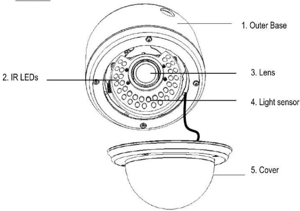
2. MAJOR PARTS: NAMES AND FUNCTIONS
Front View
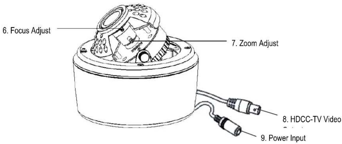
Side View
Back View
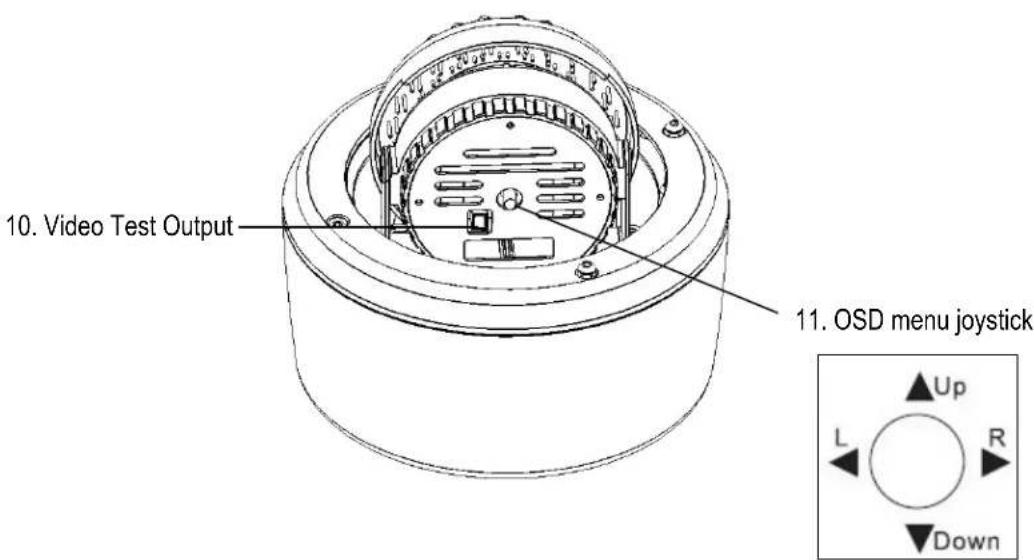
1. Base
The camera unit sets in the dome base, when it is shipped from the factory. This base is used for surface mounting, and is discarded for flush mounting.
2. IR LEDs
3. Lens
The included vari-focal, DC iris lens allows manual adjustment of the field of view (zoom & focus).
4. Light Sensor
Light sensor is used to detect the lighting level the environment. (The light sensor is "down" when the internal camera module is properly positioned).
5. Camera Cover
This cover will protect the camera from dust and damage.
6. Focus Ring
To set the focus, and loosen the focus ring knob, and turn the ring toward
7. Zoom Ring
To adjust the viewing angle, loosen the zoom ring knob. Turn the ring toward
8. HDcctv Video Output
Please connect to the BNC connector of the cable from the HD DVR or HDcctv monitor.
9. Power Input
Please connect this connector to a 12VDC or 24VAC power source.
10. Test Video Output Connector
When installing the camera, you can use this video connector to connect a portable monitor. This will allow you to easily adjust camera's field of view and focus.
11. OSD Menu joystick:
Use the joystick to move the cursor Upwards/Downwards. This is used to select the item to be set.
Tilt the stick to the right or left. This is used to select or adjust the parameters of the selected item.
Press in on the stick to enter the setup menu. If the item has its own setting menu (sign ←), press the stick again to display the sub-menu.
3. 3-AXIS GIMBAL BRACKET
The 3-axis gimbal enables installers to easily mount the camera on a wall or ceiling and then using the built in tilt and dual axis 180° twist, to adjust the viewing angle to the desired direction. With this unique 3-axis positioning system, installers can capture images from virtually any angle, without compromising performance.
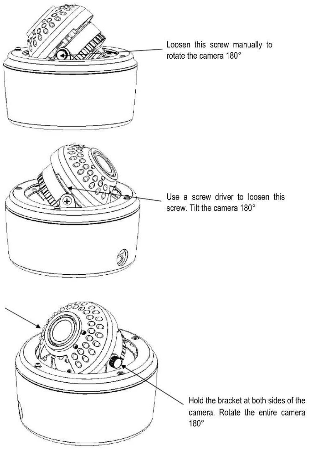
4. INSTALLATION
An EDH5240 camera may be mounted in two ways: surface mount and flush mount. Select the one that meets your needs.
Installation - Surface Mount
- Paste the drilling template on the ceiling or wall. Please refer to the drilling template below.
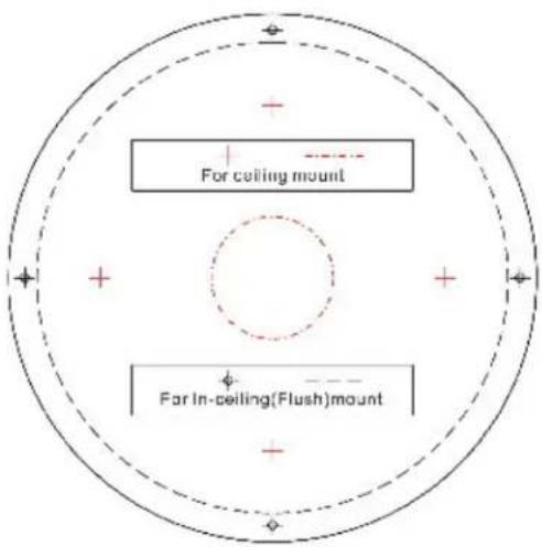
- Use the appropriate tool to drill the INNER holes, and a clearance hole for the power and video wires.
Note: The minimum recommended material thickness is 1 cm.
- Use the plastic anchors and push them into the 4 small holes, to fix the outer ring into ceiling or wall.

natural_image
Simple diagram of a horizontal beam supported by four identical mechanical components (no text or symbols)-
Remove dome cover (4 captive hex head screws); remove inner base from outer base (4 Phillips head screws – retain these for later re-assembly).
-
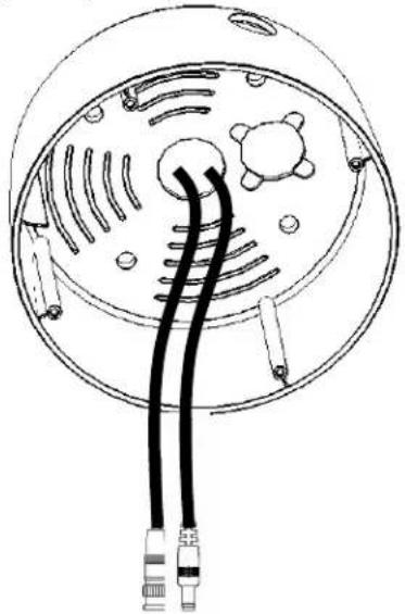
Pull the cables to be connected to power and video cables into the outer base from the ceiling or wall. Attach power supply pigtail adapter to power wire if needed.
natural_image
Technical line drawing of a mechanical component with two black cables and mounting holes (no text or symbols)- Take a long Phillips pan head screw with a washer and tighten it into a plastic anchor. Repeat the same step until all the 4 screws are fixed to the wall.
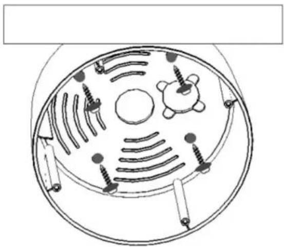
natural_image
Diagram of a circular mechanical or biological structure with internal components and screw-like elements (no text or labels)-
Attach power and video cables from source to cables from camera and push excess wire back into hole.
-
Insert inner base into outer base and secure using the 4 Phillips removed in the earlier step. Preposition camera so it is facing approximately in the desired direction.
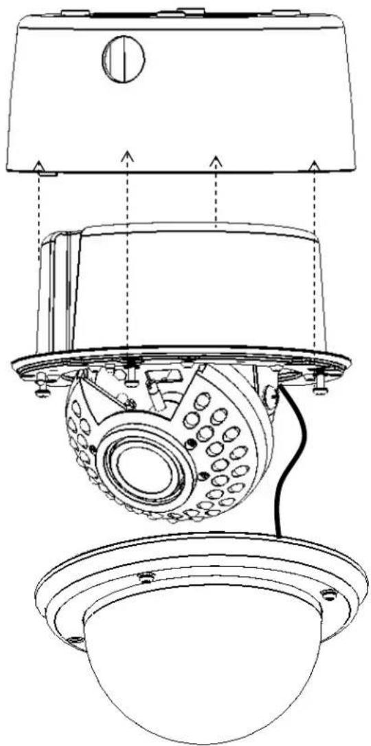
natural_image
Technical line drawing of a security camera module with no visible text or symbols-
Attach video test cable to test point on rear of camera module. Aim and focus the camera. Remove test cable.
-
Once the camera view is as desired, attach the cover to outer base with the captive hex head screws.
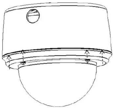
natural_image
Technical line drawing of a mechanical component with a circular top and flange (no text or symbols)Installation - Flush Mount
- Paste the drilling template on the ceiling or wall. Please refer to the drilling template below.
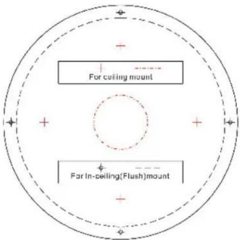
- Use the appropriate tool to drill the OUTER holes; carefully cut along the dashed circle to create a clearance hole for the inner base unit.
Note: The minimum recommended material thickness is 1 cm.
- Pull the cables to be connected to power and video cables from ceiling. Attach the power pigtail adapter if necessary.
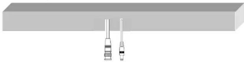
natural_image
Diagram of two mechanical components with shafts, no text or symbols present-
Remove dome cover (hex, captive screws)
-
Unscrew the 4 Philips screws (retain for future use) to detach the inner base from the outer base. Set aside the outer base.
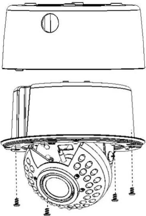
natural_image
Technical line drawing of a mechanical device with internal components and mounting holes (no text or symbols)- Screw the 2 spring tabs in the orientation shown to the slots at both sides of the inner base using the 4 Philips head screws provided. Attach the screws to the places marked "Fix".
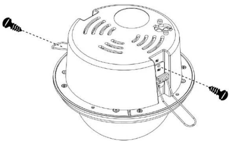
natural_image
Technical line drawing of a mechanical component with mounting flanges and a handle (no text or symbols)- Attach power and video cables from source to cables from camera and push excess wire back into hole. Fold the spring tabs up.
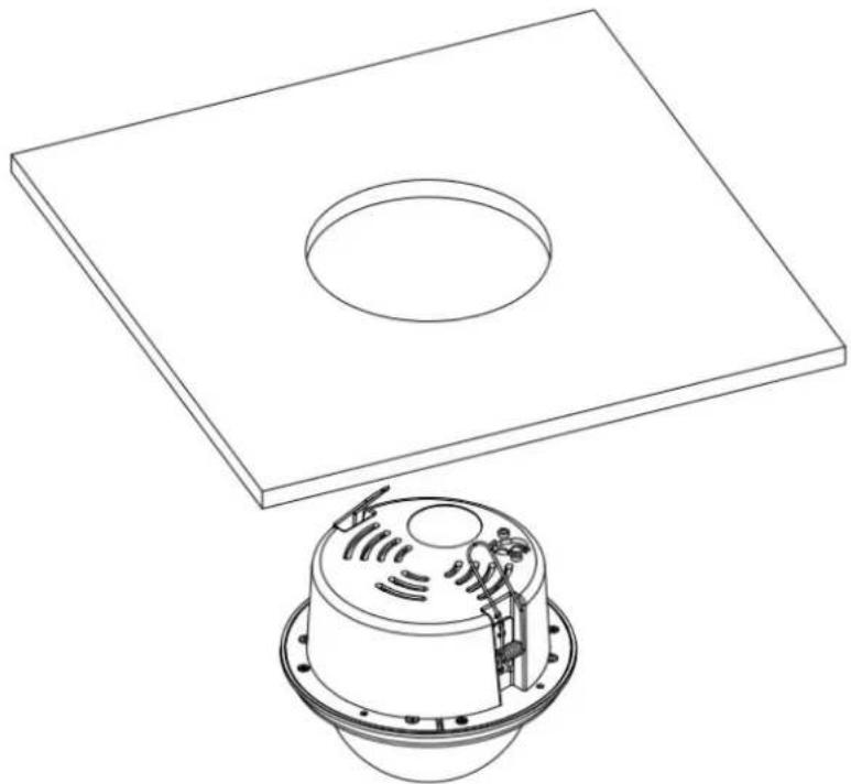
natural_image
Technical line drawing of a square plate with a circular recess and a small cylindrical component with internal components (no text or symbols)- Preposition camera so it is facing approximately in the desired direction.
- Push the entire inner base into ceiling while holding the spring tabs with both hands.
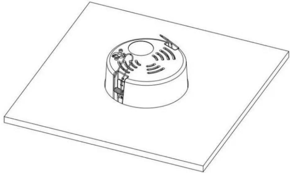
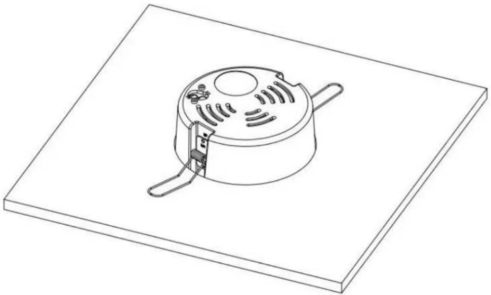
natural_image
Isometric line drawing of a mechanical component with a circular base and internal structure (no text or symbols)- The spring tabs will open automatically to support the camera against the ceiling.
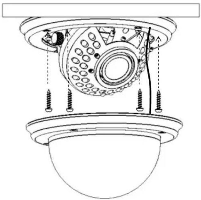
natural_image
Isometric line drawing of a pot with cooling fins and a handle, placed on a rectangular base (no text or symbols)- Use the long Phillips pan head screws (x4) provided to screw the base to the ceiling. Do NOT use washers.
natural_image
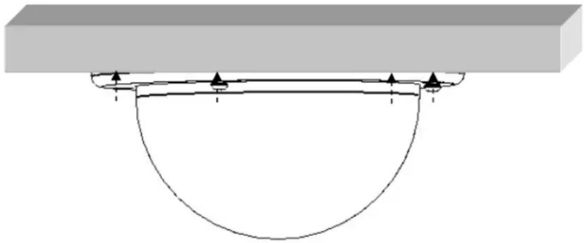
Technical line drawing of a mechanical assembly with screw fasteners and a central circular component (no text or symbols)- Attach video test cable to test point on rear of camera module. Aim and focus the camera. Remove test cable.
- Screw the cover back to the base with captive hex head screws.
natural_image
Pure diagram of a beam supported by a curved support, without any text, numbers, or symbols4. OSD Menu & Configuration
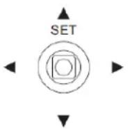
Access the user setup menu screen:
I. Press inward on the end of the joystick
The menu screen will appear on the monitor.
II. Navigating with the joystick
Angle the joystick ▲ or ▼ to move the cursor up or down. Angle the joystick ◀ or ▶ to adjust the mode or value of a setting.
III. Switching to sub-menu screens
When an item with sub-menu is selected, press inward on the end of the joystick to switch to the sub-menu for further settings.
IV. Return to previous page
Press the SET button to return to previous page if the choice displayed is Return.
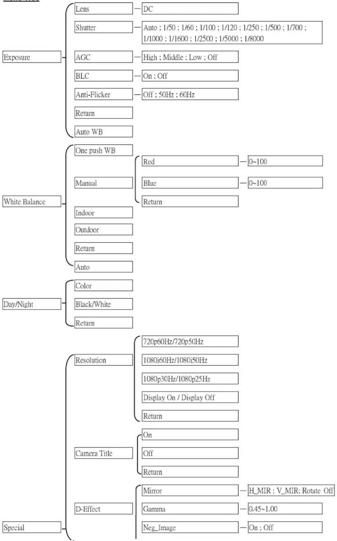
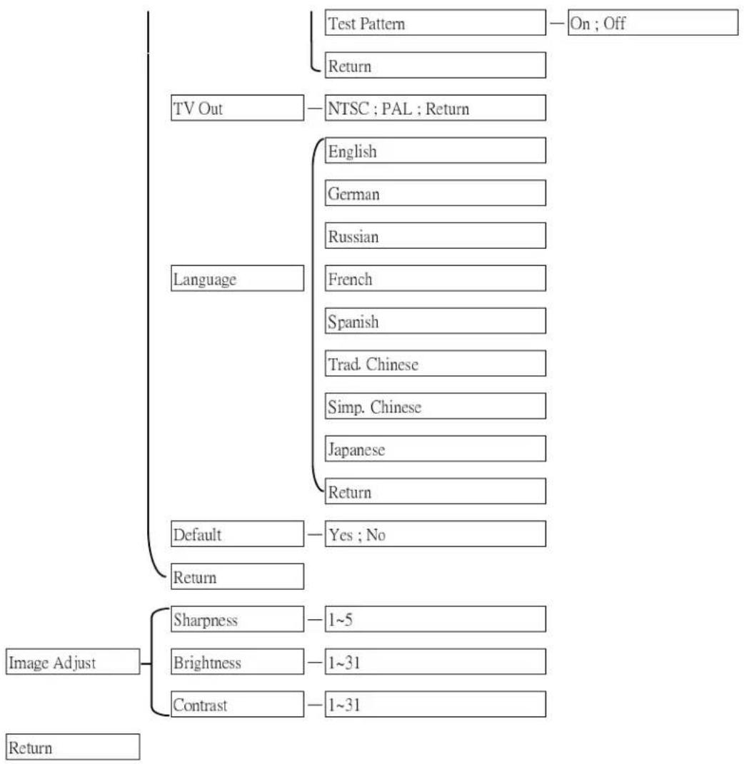
Menu Tree
flowchart
graph TD
    A["Exposure"] --> B["Lens"]
    A --> C["Shutter"]
    A --> D["AGC"]
    A --> E["BLC"]
    A --> F["Anti-Flicker"]
    A --> G["Return"]
    A --> H["Auto WB"]

    I["White Balance"] --> J["One push WB"]
    I --> K["Manual"]
    I --> L["Indoor"]
    I --> M["Outdoor"]
    I --> N["Return"]
    I --> O["Auto"]

    P["Day/Night"] --> Q["Color"]
    P --> R["Black/White"]
    P --> S["Return"]

    T["Special"] --> U["Resolution"]
    T --> V["Camera Title"]
    T --> W["D-Effect"]

    B --> X["DC"]
    C --> Y["Auto ; 1/50 ; 1/60 ; 1/100 ; 1/120 ; 1/250 ; 1/500 ; 1/700 ; 1/1000 ; 1/1600 ; 1/2500 ; 1/5000 ; 1/8000"]

    D --> Y
    E --> Z["High ; Middle ; Low ; Off"]
    F --> AA["On ; Off"]
    G --> AB["Off ; 50Hz ; 60Hz"]

    J --> AC["Red"]
    J --> AD["Blue"]
    J --> AE["Return"]

    U --> AF["720p60Hz/720p50Hz"]
    U --> AG["1080i60Hz/1080i50Hz"]
    U --> AH["1080p30Hz/1080p25Hz"]
    U --> AI["Display On / Display Off"]
    U --> AJ["Return"]

    V --> AK["On"]
    V --> AL["Off"]
    V --> AM["Return"]

    W --> AN["Mirror"]
    W --> AO["Gamma"]
    W --> AP["Neg_Image"]

    AF --> AQ["H_MIR ; V_MIR; Rotate Off"]
    AG --> AR["0~100"]
    AH --> AS["0~100"]

    AC --> AT["On; Off"]
flowchart
graph TD
    A["TV Out"] --> B["Test Pattern"]
    A --> C["Return"]
    B --> D["On ; Off"]
    C --> E["NTSC ; PAL ; Return"]
    F["Language"] --> G["English"]
    F --> H["German"]
    F --> I["Russian"]
    F --> J["French"]
    F --> K["Spanish"]
    F --> L["Trad. Chinese"]
    F --> M["Simp. Chinese"]
    F --> N["Japanese"]
    F --> O["Return"]
    P["Default"] --> Q["Yes ; No"]
    R["Return"] --> S["1~5"]
    T["Image Adjust"] --> U["Sharpness"]
    T --> V["Brightness"]
    T --> W["Contrast"]
    X["Return"] --> Y["1~31"]
Press Set button to enter SETUP Menu. In SETUP menu, use the joystick to make settings User can do camera settings including Exposure, White balance, Day/Night, Special and Image adjust. Please select the item by moving the joystick UP or DOWN then press SET to enter these settings. Move the joystick to the last option which is "Return" to return to live view.
4.1 Exposure
In this section, user can do camera settings including Lens, Shutter, Iris, AGC, BLC and Anti-flicker. Please select the item by moving the joystick UP or DOWN. Select "Return" to return to the previous menu.
4.1.1 Lens
DC mode is fixed in Lens level for EDH5240 camera.
4.1.2 Shutter
Select the shutter mode by moving the joystick LEFT or RIGHT.
Select from Auto,1/50,1/60,1/100,1/120,1/250,1/500,1/700,1/1000,1/1600,1/2500,1/5000 and 1/8000.
4.1.3 AGC (Auto Gain Control – basic low light signal amplification)
Select the level you would like to choose by moving the joystick LEFT or RIGHT. The more the level of gain increases, the brighter the screen, but the level of noise increases as well. Please select from High, Middle, Low and Off.
4.1.4 BLC
Select "On" or "Off" by moving the joystick LEFT or RIGHT. Video gain can be adjusted automatically to correct the exposure of subjects that are in front of a bright light source.
4.1.5 Anti-Flicker
Selections are Off, 50Hz and 60Hz. Camera will adjust the shutter to reduce the flicker caused by fluorescent light when manual lens is used.
4.2 White Balance Control
The screen color can be adjusted by using the White Balance function.
Please select one of the 5 modes below by moving the joystick UP or DOWN then press "Set" button to save the setting:
AWB
This mode can be used within the color temperature range from 2,500°K to 10,000°K.
One Push WB
Enable one push trigger for white balance mode. This holds the white balance at a specific color temperature until the next command trigger is given.
Manual
The manual adjustment mode enables a more precise adjustment. Set the suitable color temperature, and increase or decrease the red and blue color values at the same time while checking the color changes of the objects in view.
Return: Select "Return" to saves all settings in this menu and returns to the previous menu.
Indoor
Select this option when the color temperature is 4,000^ K.
Outdoor
Select this option when the color temperature is 5,000\~6,500°K.
Select "Return" to return to the previous menu.
4.3 Day/Night
These settings control the operation of the camera when the illumination level changes. Choices are Color at all times; B/W at all times; or color when illumination is bright, switching to B/W in low light.
Please select one of the 3 modes below by moving the joystick UP or DOWN then press "Set" button to save the setting:
- AUTO: The picture switches to color in a normal (bright) environment and switches to B/W when the ambient illumination is low. The switching point is determined by the AGC level.
• COLOR: The picture is always displayed in color, even at low light levels.
• B/W: The picture is always displayed in B/W.
Select "Return" to return to the previous menu.
NOTE:
AGC selection must be set as middle or high in order to employ the auto switching function.
4.4 Special
In this section, user can do special settings including Resolution, Camera Title, D-Effect, TV-Out, Language and Default. Please select the item by moving the joystick UP or DOWN then press SET to enter the settings. Select "Return" to return to the previous menu.
4.4.1 Resolution
-
Select camera resolution from 720p60Hz; 1080i60Hz or 1080p30Hz when TV output format is NTSC, 720p50Hz; 1080i50Hz or 1080p25Hz when TV output format is PAL by moving the joystick UP or DOWN then press "Set" button to save the setting
-
Display On: Press "Set" to switch between On/Off, whether to show current resolution.
Select "Return" to return to the previous menu.
4.4.2 Camera Title
Select "On" by moving the joystick UP or DOWN then press "Set" to enter the setting. Input a camera title by moving the joystick UP and Down, cursor will navigate among characters and numbers. The available letters are A-Z and 0-9. Press "Set" key to confirm. Move the joystick Left and Right to move the cursor among the same level.
Select "Off" by moving the joystick UP or DOWN then press "Set" to disable the camera title display.
Select "Return" to return to the previous menu.
4.4.3 D-Effect
In this section, user can do camera settings including Mirror, Gamma and Neg_Image. Please select the item by moving the joystick UP or DOWN. Select "Return" to return to the previous menu.
4.4.3.1 Mirror
Select one of the 4 modes below by moving the joystick LEFT or RIGHT.
-Off: Disable the effects.
-H-MIR: Sets a horizontal image inversion.
-V-MIR: Set a vertical image inversion.
- Rotate: Rotate the image 180°.
4.4.3.2 Gamma
Select the Gamma level by moving the joystick LEFT or RIGHT. Adjustable based on TV or PC's specification.
4.4.3.3 NEG\_IMAGE
Select Neg_Image On or Off by moving the joystick LEFT or RIGHT. Allows user to create a negative of the original image. A negative image is a tonal inversion of a positive image, in which light areas appear dark and vice versa. A negative color image is additionally color reversed, with red areas appearing cyan, greens appearing magenta and blues appearing yellow.
4.4.3.3 Test Pattern
Select Test Pattern On or Off by moving the joystick LEFT or RIGHT. Allows user to test the image and make any adjustment if necessary. (Test video output connector has to be connected properly to a portable monitor).
4.4.4 TV standard
Select video format of TV standard by moving the joystick UP or DOWN then press "Set" button to save the setting. Selectable from NTSC and PAL format.
Select "Return" to return to the previous menu.
4.4.5 Language
Select OSD language. EDH5240 camera supports multiple languages including English, German, Russian, French, Spanish, Traditional Chinese, Simplified Chinese and Japanese. Move the joystick UP or DOWN to select a language then press "Set" button to save the setting.
Select "Return" to return to the previous menu.
4.4.6 Default
Select "Yes" to load system settings to default factory values. Or select "No" to disregard this option.
4.5 Image Adjust
In this section, user can adjust Sharpness, Brightness and Contrast of the image. Please select the item by moving the joystick UP or DOWN. Select "Return" to return to the previous menu.
4.5.1 Sharpness
Select the sharpness level by moving the joystick LEFT or RIGHT. The contour of the video image becomes cleaner and more easily distinguished as the level of Sharpness increases. If the level is set too high, it may affect the video image and cause noise. The available range of level is 1\~5.
4.5.2 Brightness
Select the brightness level by moving the joystick LEFT or RIGHT. To increase or decrease object brightness of images. It is adjustable from 1\~31.
4.5.3 Contrast
Select the contrast level by moving the joystick LEFT or RIGHT. To increase or decrease object contrast of images. It is adjustable from 1\~31.
EverFocus Electronics Corp.
EverFocus Taiwan:
12F, No.79, Sec. 1, Shin-Tai Wu Road,
Hsi-Chih, Taipei, Taiwan
TEL: +886 2 2698 2334
FAX: +886 2 2698 2380
www.everfocus.com.tw
marketing@everfocus.com.tw
EverFocus China - Beijing:
Room 609, Technology Trade Building,
Shangdi Information Industry Base,
Haidian District, Beijing 100085, China
TEL: +86 10 6297 3336\~39
FAX: +86 10 6297 1423
www.everfocus.com.cn
marketing@everfocus.com.cn
EverFocus USA - California:
1801 Highland Avenue, Unit A, Duarte, CA 91010, USA
TEL: +1 626 844 8888
FAX: +1 626 844 8838
www.everfocus.com
sales@everfocus.com
EverFocus Japan:
5F, Kinshicho City Building, 2-13-4
Koto-Bashi, Sumida-Ku, Tokyo, 130-0022, Japan
TEL: +81 3 5625 8188
FAX: +81 3 5625 8189
www.everfocus.co.jp
info@everfocus.co.jp
EverFocus India:
Suite 803, Housefin Bhavan, C-21, Bandra Kurla
Complex, Bandra (East), Mumbai 400051, India
TEL: +91 22 6128 8700
FAX: +91 22 6128 8705
www.everfocus.in
sales@everfocus.in
Your EverFocus product is designed and manufactured with high quality materials and components which can be recycled and reused.
This symbol means that electrical and electronic equipment, at their end-of-life, should be disposed of separately from your household waste. Please, dispose of this equipment at your local community waste collection/gathering water.
In the European Union there are separate collection systems for used electrical and electronic product. Please, help us to conserve the environment we live in!
EverFocus Europe - Germany:
Albert-Einstein-Strasse 1, D-46446
Emmerich, Germany
TEL: +49 2822 93940
FAX: +49 2822 939495
www.everfocus.de
info@everfocus.de
EverFocus China - Shenzhen:
4F, No. 2, D4 Building, Wan Yelong
Industrial Park, Tangtou Road, Shiyan,
Baoan, Shenzhen, Guangdong 518101, China
TEL: +86 755 2765 1313
FAX: +86 755 2765 0337
www.everfocus.com.cn
marketing@everfocus.com.cn
EverFocus USA - New York:
415 Oser Avenue, Unit S, Hauppauge, NY 11788, USA
TEL: +1 631 436 5070
FAX: +1 631 436 5027
www.everfocus.com
sales@everfocus.com
EverFocus Europe - UK:
Unit 12, Spitfire Business Park,
Hawker Road, Croydon Surrey, CR0 4WD, UK
TEL: +44 20 8649 9757 / +44 845 430 9999
FAX: +44 20 8649 9907
www.everfocusuk.co.uk
salesuk@everfocus.com

EverFocus®
P/N: 4605PD5240B010A
- EverFocus®
- Megapixel Full HDcctv Indoor IR Dome Camera
- PRECAUTIONS
- TABLE OF CONTENTS
- PRODUCT OVERVIEW
- Main Features
- Package Contents
- Specifications
- Dimensions
- MAJOR PARTS: NAMES AND FUNCTIONS
- Base
- IR LEDs
- Lens
- Light Sensor
- Camera Cover
- Focus Ring
- Zoom Ring
- HDcctv Video Output
- Power Input
- Test Video Output Connector
- OSD Menu joystick:
- 3-AXIS GIMBAL BRACKET
- INSTALLATION
- Installation - Surface Mount
- Installation - Flush Mount
- OSD Menu & Configuration
- Press inward on the end of the joystick
- Navigating with the joystick
- Switching to sub-menu screens
- Return to previous page
- Exposure
- Lens
- Shutter
- AGC (Auto Gain Control – basic low light signal amplification)
- BLC
- Anti-Flicker
- White Balance Control
- AWB
- One Push WB
- Manual
- Indoor
- Outdoor
- Day/Night
- NOTE:
- Special
- Resolution
- Camera Title
- D-Effect
- Mirror
- Gamma
- NEG\_IMAGE
- Test Pattern
- TV standard
- Language
- Default
- Image Adjust
- Sharpness
- Brightness
- Contrast
- EverFocus Electronics Corp.
- EverFocus Taiwan:
- EverFocus China - Beijing:
- EverFocus USA - California:
- EverFocus Japan:
- EverFocus India:
- EverFocus Europe - Germany:
- EverFocus China - Shenzhen:
- EverFocus USA - New York:
- EverFocus Europe - UK:
Brand : EverFocus
Model : EDH5240
Category : Security Camera