EHD650 - Security Camera EverFocus - Free user manual and instructions
Find the device manual for free EHD650 EverFocus in PDF.


| Product Type | Vandal-Resistant Rugged Dome Camera |
| Image Sensor | 1/3" Color Digital Pixel System (DPS) sensor |
| Horizontal Resolution | Over 480 TVL |
| Wide Dynamic Range | 95 dB typical, 120 dB max |
| Day/Night Function | True Day/Night (moving OLPF and glass) |
| Minimum Illumination | 0.08 Lux (F=1.2, DSS x32) |
| Video Output | BNC 1.0Vp-p, 75 Ohm |
| Lens | Vari-focal, auto iris, f=2.9~10 mm or f=9~22 mm |
| Electronic Shutter | 1/50(1/60)~1/100,000 |
| Sync Mode | Line Lock / Internal |
| Weatherproof Rating | IP66 |
| Vandal Resistance | Yes, withstands 10 lb sledgehammer blow |
| Heater | Built-in, activated below 10°C (50°F) |
| Power Source | 24VAC |
| Power Consumption | 6 VA (heater off), 20.5 W (heater on) |
| Operating Temperature | -40°C to 50°C (-40°F to 122°F) |
| Humidity | 20% to 80% |
| Dimensions (W x H x D) | 130 mm x 98.9 mm x 130 mm (5.1" x 3.9" x 5.1") |
| Weight | 1 kg (2.2 lbs) |
| Housing Material | Polycarbonate shell with aluminum die-cast base |
| Security Screws | Unique security screw lock |
| Cleaning | Use soft cloth for body; lens tissue/ethanol for sensor and lens |
| OSD Menu | Yes, via mini-joystick controller |
| Package Contents | Camera, mounting accessories, wrench, weather-proof conduit, cables, desiccant pack, manual |
| Certifications | FCC, CE |
Frequently Asked Questions - EHD650 EverFocus
User questions about EHD650 EverFocus
0 question about this device. Answer the ones you know or ask your own.
Ask a new question about this device
Download the instructions for your Security Camera in PDF format for free! Find your manual EHD650 - EverFocus and take your electronic device back in hand. On this page are published all the documents necessary for the use of your device. EHD650 by EverFocus.
USER MANUAL EHD650 EverFocus
natural_image
Close-up of a metallic camera lens with visible lens and mounting holes (no text or symbols)EVERFOCUS
1/3" Wide-Dynamic
True D/N Rugged Dome Color Camera
Operation Instructions
Model No. EHD650
Please read this manual first for correct installation and operation. This manual should be retained for future reference. The information in this manual was current when published. The manufacturer reserves the right to revise and improve its products. All specifications are therefore subject to change without notice.
PRECAUTIONS
- Do not install the camera near electric or magnetic fields.
Install the camera away from TV, radio transmitter, magnet, electric motor, transformer, audio speakers since the magnetic fields generate from above devices will distort the video image.
- Never disassemble the camera nor put impurities in it.
Disassembly or impurities may result in trouble or fire.
- Never face the camera toward the sun.
Direct sunlight or severe ray may cause fatal damage to sensor and internal circuit.
- Keep the power cord away from wet and never touch the power cord with wet hands.
Touching the wet power cord with hands or touching the power cord with wet hands may result in electric shock.
- Never install the camera in areas exposed to water, oil or gas.
Water, oil or gas may result in failure, electric shock or file.
- Cleaning
Do not touch the surface of sensor by hand directly. Use a soft cloth to remove the dirt from the camera body. Use lens tissue or a cotton tipped applicator and ethanol to clean the sensor and the camera lens.
- Do not operate the camera beyond the specified temperature, humidity or power source ratings.
Use the camera at temperatures within -40^ 50^ ( -40^ 122^ ) and humidity between 20%\~80%. The input power source is 24VAC.
TABLE OF CONTENTS
1. PRODUCT OVERVIEW....3
1.1 MAIN FEATURES....3
1.2 PACKAGE CONTENTS....4
1.3 SPECIFICATIONS .... 5
1.4 DIMENSIONS....6
1.5 HARDWARE OVERVIEW....7
2. INSTALLATION....8
2.1 INSTRUCTION FOR ROTATING THE CAMERA MOUNTING....9
2.2 MOUNTING CAMERAS ON THE CEILING/WALL 10
2.3 CONDUIT CABLE AND CONNECT POWER AND VIDEO ....11
2.4 ADJUST LENS ZOOM AND FOCUS AND VIEW 14
3. HOW TO CONTROL OSD MENU....15
3.1 WHERE IS OSD CONTROLLER.... 15
3.2 GENERAL OPERATION INSTRUCTION....15
4. MAIN MENU 17
4.1 SETUP ID 17
4.2 LENS 18
4.3 WDR (WIDE DYNAMIC RANGE)....19
4.4 WB CONTROL....19
4.5 AGC 20
4.6 LOW LIGHT....21
4.7 SYNC 22
4.8 DAY/NIGHT 23
4.9 EXIT MENU 23
1. PRODUCT OVERVIEW
The most technically advanced EHD650 is the newest vandal-resistant Color Rugged Dome Camera from EverFocus Electronics. The Color Rugged Dome Camera can withstand a blow from a 10-pound sledgehammer and has a built-in heater that allows for operation in low temperatures. It is perfect for all high-profile crime-prone applications such as building, entrances, retail stores, and shopping malls. The EHD650 is unquestionably one of the world's toughest cameras and is your best choice for vandal resistance.
1.1 Main Features
■ 1/3" Color Digital Pixel System (DPS) sensor
Each pixel is processed independently to get clear and usable images
■ High resolution: Over 480 horizontal TVL
■ Superior Wide Dynamic Image Quality
Film-like colors are described under various light conditions even in high dynamic range scenes. Dynamic Range is greater than 120dB.(max)
■ True Day Night function:
True day/night by moving OLPF and glass. Converts to B/W mode when light is low
■ OSD function control
■ Vandal proof
■ Vari-focal lens for auto iris control
■ Line Lock mode
■ Polycarbonate shell withstand the impact of 10 pounds sledgehammer, smoke color or clear as option
■ Aluminum die-casting base, smoke color or clear as option
■ Unique security screw locked
■ Operating temperature -40^ 50^ ( -40^ 122^ )
■ Heater triggered when temperature less than 10^ C ( 50^ F)
1.2 Package Contents
- Camera Unit x 1
● Mounting Accessory includes: - Screws x 4
- Expanding Screws x 4
- Wrench x 1
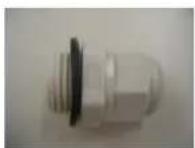
● Weather-proof Conduit x 1
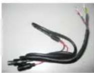
- Extension Power Cable and Video cable x 1
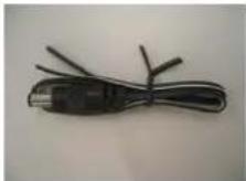
- Extension Power Cable x 1
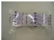
- Desiccant Pack x 1
- Manual x 1
OPTIONAL ACCESSORIES
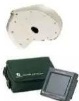
● Wall Mount Bracket (BA-EHD)
EN220 5.6-inch LCD Test Monitor
1.3 Specifications
| Pickup Device | 1/3" DPS Wide Dynamic range sensor |
| Video Format | NTSC or PAL |
| Scanning System | NTSC: 525 TV lines, 60 fields/secPAL: 625 TV lines, 50 fields/sec. |
| Picture Elements | 720(H) X 540(V) |
| Horizontal Resolution | 480TVL |
| Sensitivity | 0.08Lux/F=1.2 (DSS x 32) |
| S/N Ratio | Over 48dB |
| Electronic Shutter | 1/50(1/60)~1/100,000 |
| Lens Type | Vari-focal lens, Auto Irisf=2.9~10mmf=9~22mm*Lens models and availability vary in different regions |
| OSD Menu | Yes |
| Back Light Comp. | Yes |
| Auto Gain Control | Yes |
| Auto White Balance | Yes |
| Flickerless | Yes |
| Slow Shutter | Up to 32x (2, 4, 8, 16, 32) |
| Dynamic Range | 95dB typical, 120dB max |
| Gamma Correction | 0.45 |
| Video Output | BNC 1.0Vp-p, 75ohm |
| Sync. Mode | Line Lock/Internal Sync |
| Weatherproof | IP66 |
| Vandal Resistant | Yes |
| Heater | Yes, built-in |
| Power Source | 24VAC |
| Power Consumption | 24VAC: 6VA max. (heater OFF)24VAC: 20.5W max. (heater ON) |
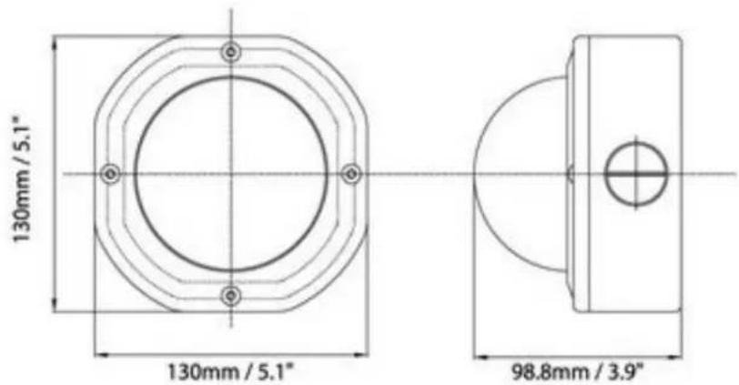
| Dimensions | 130mm(W) x 98.9mm(H) x 130mm(D);5.1"(W) x 3.9"(H) x 5.1"(D) |
| Weight | 1 kg; 2.2 lbs |
| Operating Temperature | -40°C~50°C; -40°F~122°F (20%~80% Humidity) |
| Certifications | FCC/CE |
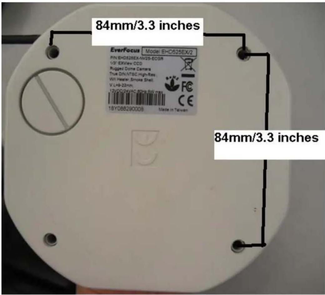
1.4 Dimensions
a.
b.
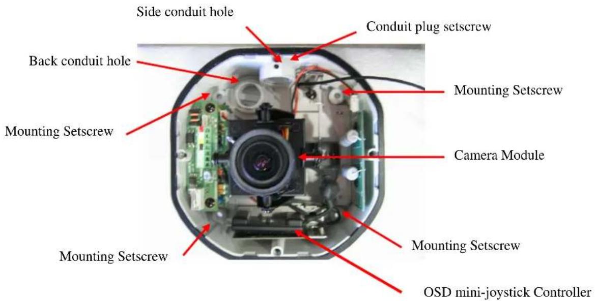
1.5 Hardware Overview
2. INSTALLATION
This section covers simple steps and detail installation. Please follow instruction for preventing any unnecessary damage.
Simple Steps:
- Open camera cover.
- Rotate camera if install on ceiling
- Drill holes on wall/ceiling. Mount cameras.
-
Connect power and video.
-
Optional connect to EN220 Test Monitor for field testing (monitor is not included).
-
Adjust lens and camera position.
-
Adjust camera setting by using the OSD controller.
-
Put in DESICCANT PACK and close the camera cover for avoiding moisture in the camera.
Detail Installation Steps:
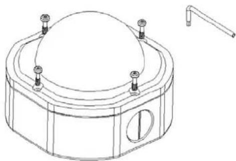
- Loosen the 4 fix screws on the housing cover by using the attached wrench (Figure 1). Please pay attention not to damage the lens.
natural_image
Technical line drawing of a mechanical component with a dome-shaped top and side ports (no text or symbols)Figure 1
- Remove the camera
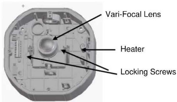
Figure 2
To remove the camera, first unplug the wire connection on the back of the camera. Then loosen the 2 locking screws on the camera base, push the camera base to the right (toward heater direction, as shown in Figure 2), remove the camera from the mounting base. Reinstall the camera and the cable while the base mounting is completed.
2.1 Instruction for rotating the camera mounting
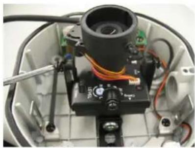
a. Please unscrew fixing screws that hold the camera module.
natural_image
Interior view of an electronic device with visible wiring and components (no text or symbols)Figure 3-1
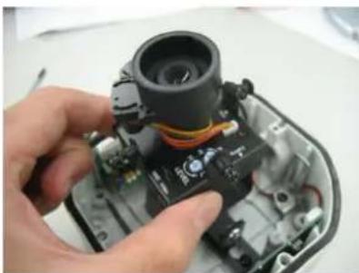
b. Remove the camera
natural_image
Close-up of a hand holding an open camera module with visible wiring and components (no text or symbols)Figure 3-2
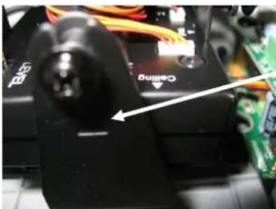
c. Aim "Ceiling" Mark to "▲" mark on camera lead frame. See figure
3-3.
natural_image
Close-up of a black mechanical component with wiring and a labeled 'Chim' button, placed on a circuit board (no readable text beyond labels)“▲” mark.
Figure 3-3
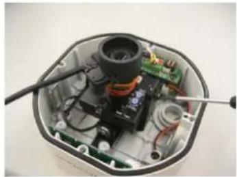
d. Tighten fixing screws and finished
natural_image
Interior view of an open electronic device showing internal components like a camera, circuit board, and wiring (no text or symbols visible)Figure 3-4
2.2 Mounting Cameras on the Ceiling/Wall
a. Mount the base to the wall or ceiling, fix the base by the 4 screws in the accessory pack.(see dimension b for drilling dimension). This dome is weighted 1.7kg, please make sure if the mounting is strengthened enough to support it, if not, please reinforce the mounting according to the environment. See figure 4.
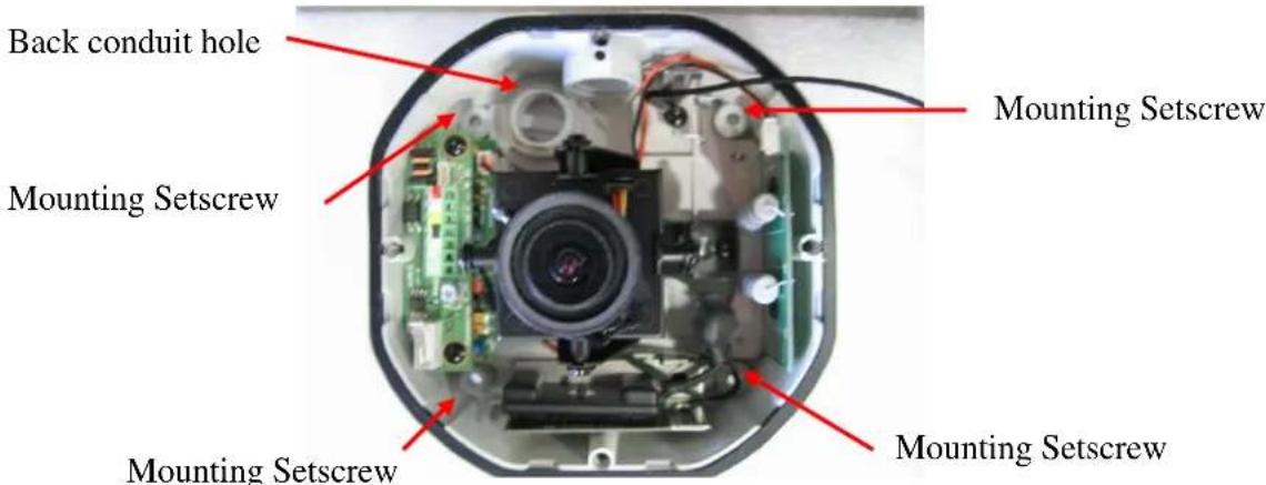
Figure 4
b. Take off cable conduit if you need to wire cable through side conduit hole. The camera comes with a conduit plug pre-installed in the PF 1/2 conduit hole on the side. The conduit plug can be removed and installed in the back conduit hole (as shown in Figure 5)
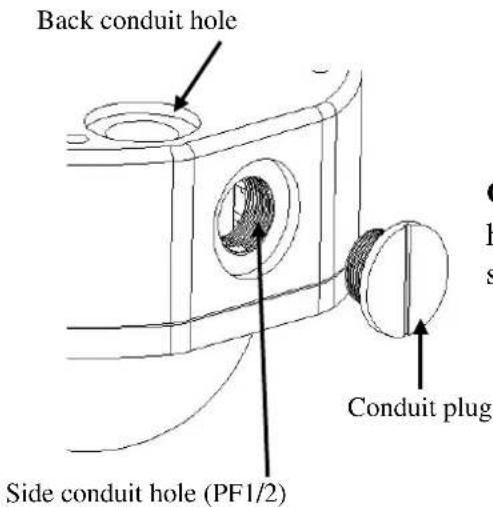
Caution: When used in the environment with high humidity, apply an appropriate gasket or sealant around the conduit connection.
Figure 5
2.3 Conduit cable and Connect Power and Video
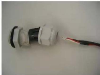
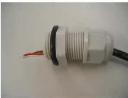
a. If you want to wire cable through side conduit hole. Find the water-proof conduit in the bag and wire power connection cable through it.
natural_image
Close-up of a white plastic connector with black and red wires attached, no visible text or symbolsFigure 6-1
natural_image
Close-up of a white plastic connector with threaded body and black cable, showing wires (no text or symbols visible)Figure 6-2
b. Connect cable conduit to the conduit hole and make it tight.

natural_image
Interior view of an electronic device showing exposed circuit board, wires, and connectors (no visible text or symbols)Figure 6-3
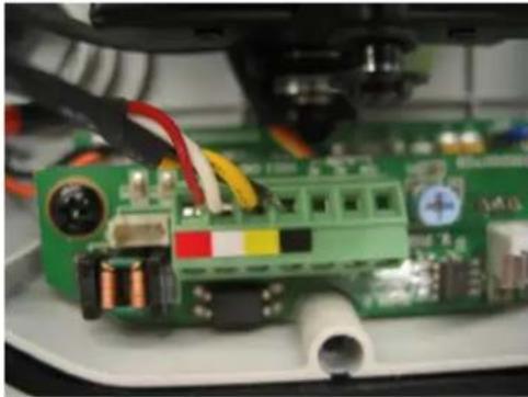
c. Connect the power supply cable (24VAC), video output to the proper connectors. The extension power has 4 colors for Power +(red), - (white) and Video(yellow), GND(black). Please match the colors with
terminal board shown as Figure 7. Yellow to yellow, Black to Black, White to white, red to red. Wrong connection will damage the camera!!
natural_image
Close-up of a green electronic circuit board with visible components and wiring (no readable text or symbols)Figure 7
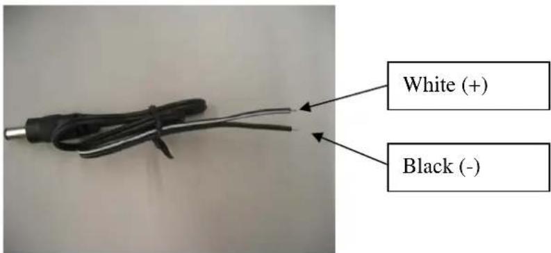
d. Connect 24VAC regulated power source to the camera. Please use power extension for connecting to it if the power adapter cable is not long enough.
e. Optional connect to Alarm(Please see figure 8 for terminal functions)
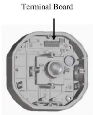
Figure 8
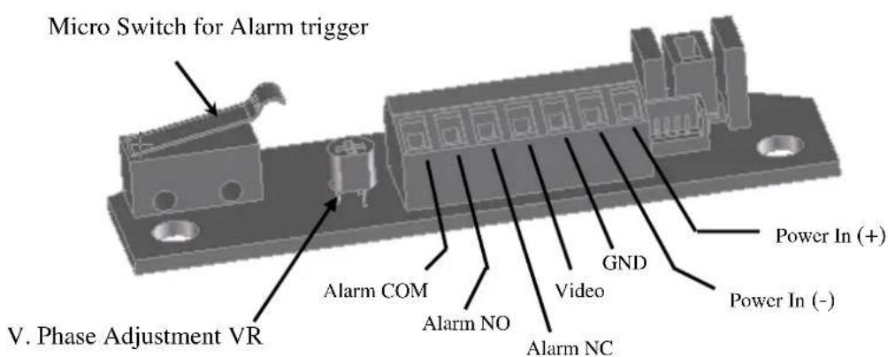
Figure 9
f. V. Phase adjustment screw is located on the termination board. The vertical phase may require adjustment to synchronize the vertical phase of the camera with other camera in the system when it is to be used in the line-lock sync mode. Make the adjustment when the vertical phase of the camera does not match with other cameras.
2.4 Adjust Lens zoom and focus and View
a. Adjust Lens zoom and focus(for vari-focal lens models)
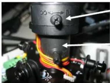
natural_image
Close-up of a mechanical assembly with colored wires and connectors (no visible text or symbols)
Figure 10
b. Adjust view angle
The camera can be rotated 360^ horizontally, 140^ vertically and 60^ 3'rd axis view angles (as shown in Figure 11). Adjust the proper camera view angle as needed.
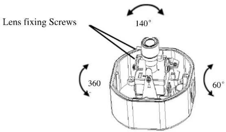
Figure 11
3. HOW TO CONTROL OSD MENU
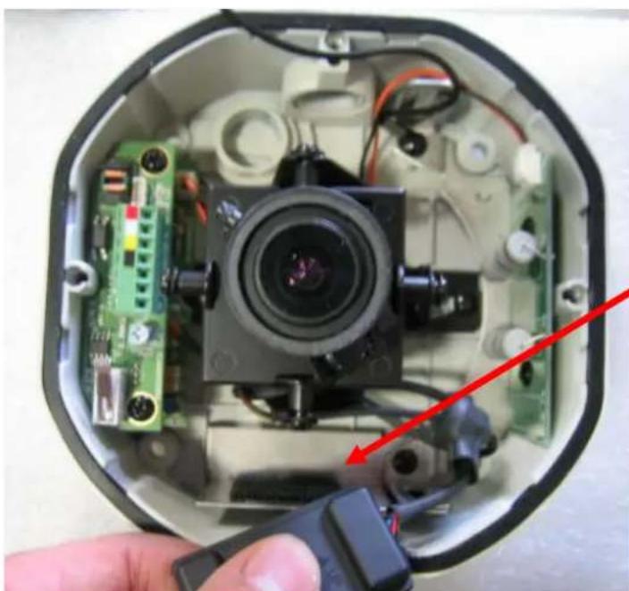
3.1 Where is OSD Controller
Detach the mini-joystick on the side of camera housing. See the following picture.
natural_image
Interior view of an open electronic device showing a camera lens and circuit board (no text or symbols visible)OSD mini-joystick controller is attached here.
3.2 General Operation Instruction
flowchart
graph TD
    A["Set button"] --> B["Star"]
    B --> C["Circle"]
    B --> D["Circle"]
    B --> E["Circle"]
    B --> F["Circle"]
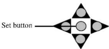
The Cursor Buttons & the SET Button
| MAIN MENU | |
| SETUP ID.. | |
| LENS | DC.. |
| WDR.. | |
| WB CONTROL | ATW |
| AGC | ON |
| LOW LIGHT | SLOW-SH.. |
| SYNC .. | |
| DAY/NIGHT | |
| EXIT MENU | |
I. Press the SET button for 3 seconds
The menu screen will appear on the monitor as the block shown above.
II. Using the cursor button
Use the cursor button ▲ or ▼ to move the cursor up or down. Use the cursor button ◀ or ▶ to adjust the mode or parameter of settings.
III. Switch to sub-menu screens
When the item with sub-menu is selected, press the SET button to switch to the sub-menu for further settings. Please refer to the figure below.
| MAIN MENU | |
| >SETUP ID.. | |
| LENS | DC.. |
| WDR.. | |
| WB CONTROL | ATW |
| AGC | ON |
| LOW LIGHT | SLOW-SH.. |
| SYNC. | |
| DAY/NIGHT | |
| EXIT MENU | |

CAMERA ID MENU
DISPLAY ID ON CAMERA ID: ID POSITION UP-LEFT PREVIOUS PAGE.
NOTE:
For those selected items with “..” sign in the end, they have the sub-menu for further settings.
IV. Return to previous page
Press the SET button to return to previous page.
V. Close the menu screen
To close the menu screen, use the cursor button to select EXIT and press the SET button.
4. MAIN MENU
4.1 Setup ID
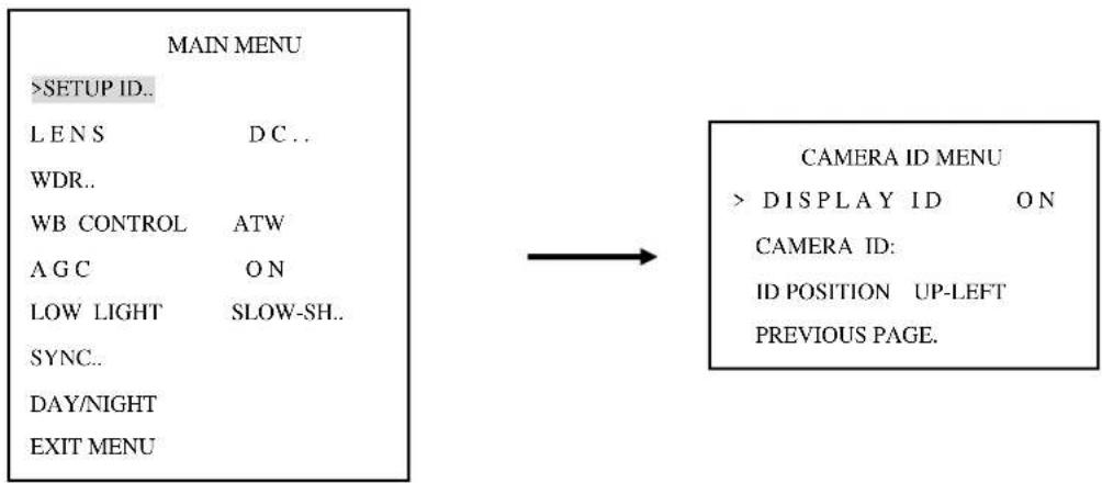
Camera Menu: Display ID/Camera ID/ID position
flowchart
graph LR
    A["MAIN MENU"] --> B[">SETUP ID.."]
    A --> C["L E N S D C .."]
    A --> D["WDR.."]
    A --> E["WB CONTROL ATW"]
    A --> F["A G C O N"]
    A --> G["LOW LIGHT SLOW-SH.."]
    A --> H["SYNC.."]
    A --> I["DAY/NIGHT"]
    A --> J["EXIT MENU"]
    K["CAMERA ID MENU"] --> L[">DISPLAY ID ON"]
    K --> M["CAMERA ID: ID POSITION UP-LEFT PREVIOUS PAGE."]
DISPLAY ID: ON/OFF.
The camera ID can be displayed on the screen by setting "ON".
CAMERA ID: When “ON” is selected, user can set the Camera ID up to 12 characters. Please refer to the table below for detailed character patterns. Use the cursor button ◀ or ▶ to locate characters (characters will display in the same order as shown in table), press the SET button to choose the character. Use the cursor button ▶ to move to the next character for setting.
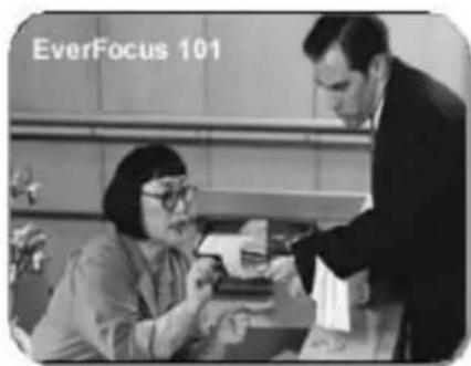
Once the characters of camera ID are all selected, press the SET button for 1 sec to close the menu and the Camera ID will show on the screen as the figure below.
Ex: CAMERA ID: EverFocus 101

| ! | " | # | $ | % | & | ' | ( | ) | * | + | , | - | . | / | θ | 1 | 2 | 3 | 4 |
| 5 | 6 | 7 | 8 | 9 | : | ; | < | = | > | ? | @ | A | B | C | D | E | F | G | H |
| I | J | K | L | M | N | O | P | Q | R | S | T | U | V | W | X | Y | Z | [ | \ |
| ] | ^ | _ | ` | a | b | c | d | e | f | g | h | i | j | k | l | m | n | o | p |
| q | r | s | t | u | v | w | x | y | z | { | | | } | ~ | i | φ | £ | ∞ | ¥ | |
| | | § | ` | © | a | « | ¬ | - | ® | - | ° | ± | 2 | 3 | ` | μ | ¶ | · | , | 1 |
| ° | » | 1⁄4 | 1⁄2 | 3⁄4 | ¿ | À | Á | Â | Ã | Ä | Â | Æ | Ç | È | É | Ê | Ë | Î | Î |
| Î | Î | Đ | Ñ | Ò | Ó | Ô | Õ | Ö | × | ∅ | Ù | Ú | Û | Ü | Ý | p | ß | à | á |
| â | ã | ä | å | æ | ç | è | é | ê | ë | ì | í | î | ì | ö | ñ | ò | ó | ô | õ |
| õ | ÷ | ø | ù | ú | û | ü | ý | þ | ÿ | ||||||||||
ID POSITION: UP-LEFT / UP-CENTER / UP-RIGHT / DWN-LEFT / DWN-CENTER / DWN-RIGHT
There are four positions can be chosen to show the CAMERA ID on the screen. Choose an ID position that will not cover the import/critical part of images.
PREVIOUS PAGE: Press SET button and you can return to the previous page.
4.2 Lens
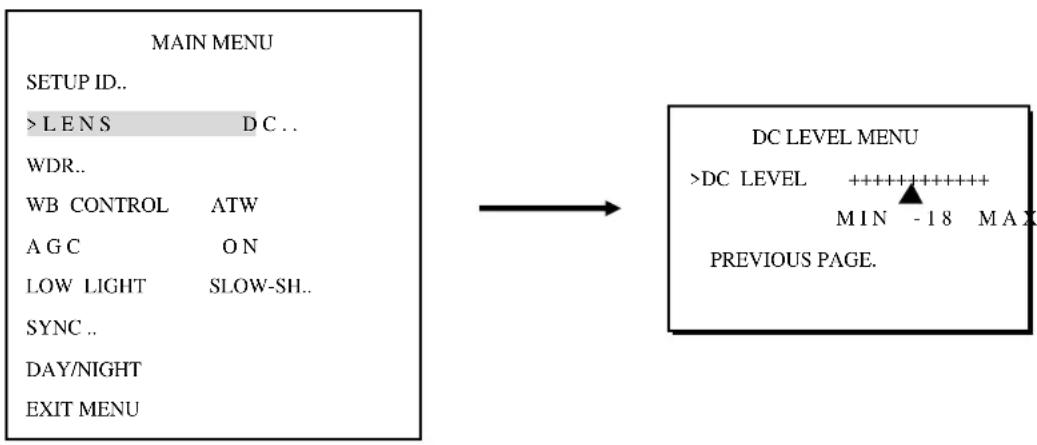
LENS-DC:
DC LEVEL: The brightness of the screen can be adjusted on DC mode in DC LEVEL. The level can be adjusted MIN -42 to 20 MAX.
PREVIOUS PAGE: Press SET button and you can return to the previous page.
flowchart
graph LR
    A["MAIN MENU"] --> B["DC LEVEL MENU"]
    B --> C[">DC LEVEL ++++++++++ MIN -18 MAX PREVIOUS PAGE."]
4.3 WDR (Wide Dynamic Range)
flowchart
graph LR
    A["MAIN MENU"] --> B["WDR MENU"]
    A --> C[">EXPO BIAS ++++++++++"]
    A --> D["WDR BIAS ++++++++++"]
    A --> E["MIN -2 MAX"]
    A --> F["PREVIOUS PAGE."]
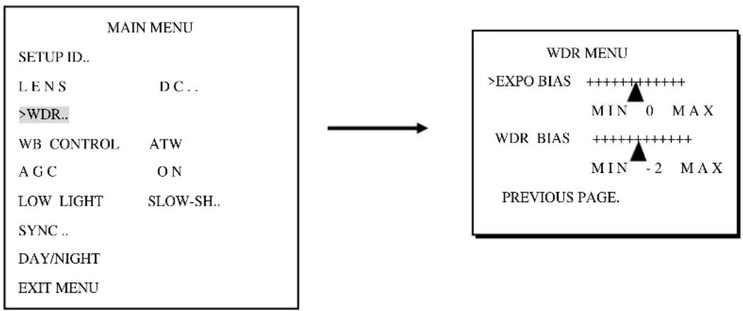
EXPO BIAS: MIN -18 \~ 18 MAX
Select exposure bias from min. -18 to max. 18.
WDR BIAS: MIN -20 \~ 20 MAX
The camera offers outstanding Wide-Dynamic Range (WDR). User can manually set the Dynamic Range by moving the tag along -20 to 20 level bar. When contrast of lighting condition is larger, increase the number, or decrease the number towards “0” if the contrast of lighting condition is smaller.
PREVIOUS PAGE: Press SET button and you can return to the previous page.
4.4 WB Control
ATW/AWB/MANUAL
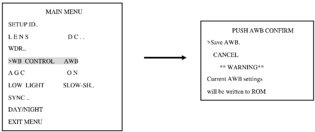
WB CONTROL: AWB (Auto White Balance).
PUSH AWB CONFIRM: This saves the current Auto White Balance setting. If lighting environment ever changes, you can change this AWB again.
CANCEL: Quit this menu without saving AWB.
flowchart
graph LR
    A["MAIN MENU"] --> B["PUSH AWB CONFIRM"]
    B --> C["->Save AWB."]
    B --> D["CANCEL"]
    D --> E{** WARNING**}
    E --> F["Current AWB settings will be written to ROM"]
    A --> G["SETUP ID.."]
    A --> H["L E N S D C .."]
    A --> I["WDR.."]
    A --> J[">WB CONTROL AWB"]
    A --> K["A G C O N"]
    A --> L["LOW LIGHT SLOW-SH.."]
    A --> M["SYNC .."]
    A --> N["DAY/NIGHT"]
    A --> O["EXIT MENU"]
WB CONTROL: ATW
ATW (Auto Tracking White Balance): This mode can be used within the color temperature range from 2,500°K to 9,500°K (eg, fluorescent light, outdoor, sodium vapor lamp or inside tunnels).
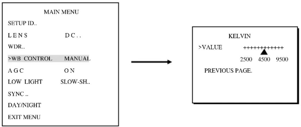
WB CONTROL: MANUAL
flowchart
graph LR
    A["MAIN MENU"] --> B["SETUP ID.."]
    A --> C["L E N S D C .."]
    A --> D["WDR.."]
    A --> E[">WB CONTROL MANUAL"]
    A --> F["A G C O N"]
    A --> G["LOW LIGHT SLOW-SH.."]
    A --> H["SYNC .."]
    A --> I["DAY/NIGHT"]
    A --> J["EXIT MENU"]

    K["KELVIN"] --> L[">VALUE ++++++++++ 2500 4500 9500 PREVIOUS PAGE."]
KELVIN: value ranges from 2500 to 9500. You could adjust White Balance manually according to environment's color temperature.
PREVIOUS PAGE: Press SET button and you can return to the previous page.
4.5 AGC
ON/OFF
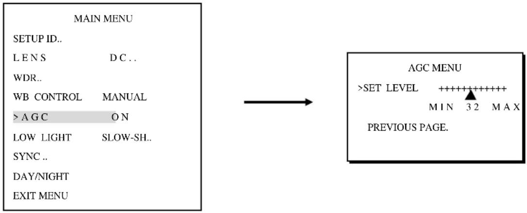
AGC: ON. By selecting ON, you can activate automatic gain control feature.
flowchart
graph LR
    A["MAIN MENU"] --> B["AGC MENU"]
    A --> C["SET LEVEL ++++++++++++++"]
    C --> D["M IN 3 2 MAX"]
    C --> E["PREVIOUS PAGE."]
AGC MENU: SET LEVEL from MIN 0 to MAX 36.
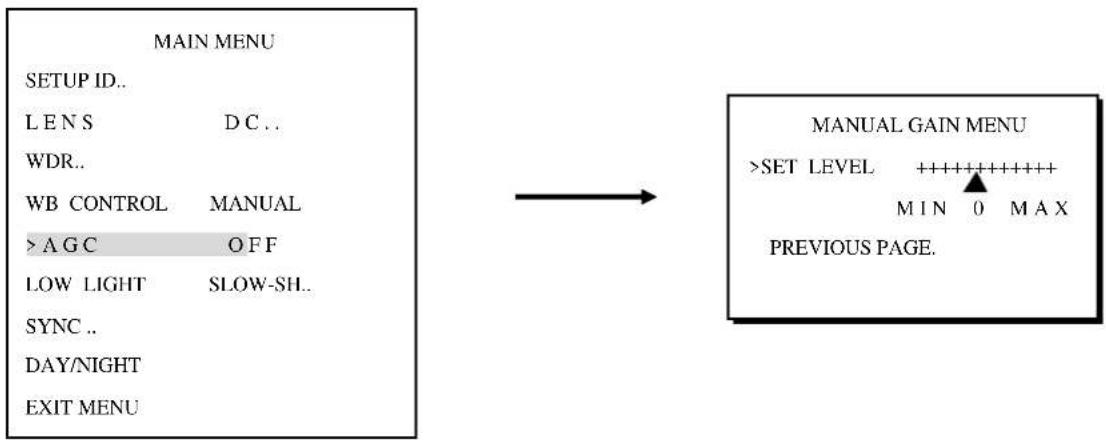
PREVIOUS PAGE: Press SET button and you can return to the previous page. AGC:OFF. It is a fixed gain adjustment.
flowchart
graph LR
    A["MAIN MENU"] --> B["SET UP ID.."]
    A --> C["LENS D.C.."]
    A --> D["WDR.."]
    A --> E["WB CONTROL MANUAL"]
    A --> F[">A G C OFF"]
    A --> G["LOW LIGHT SLOW-SH.."]
    A --> H["SYNC .."]
    A --> I["DAY/NIGHT"]
    A --> J["EXIT MENU"]
    K["MANUAL GAIN MENU"] --> L[">SET LEVEL ++++++++++"]
    L --> M["MIN 0 MAX"]
    L --> N["PREVIOUS PAGE."]
AGC MENU: SET LEVEL from MIN -34 to MAX 43. The more the level of gain increases, the brighter the screen and the level of noise increases as well.
PREVIOUS PAGE: Press SET button and you can return to the previous page.
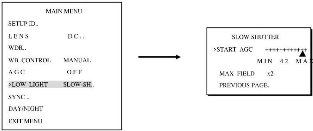
4.6 Low Light
SLOW SH../B&W SS/GAIN
flowchart
graph LR
    A["MAIN MENU"] --> B["SLOW SHUTTER"]
    A --> C["SETUP ID.."]
    A --> D["L E N S D C .."]
    A --> E["WDR.."]
    A --> F["WB CONTROL MANUAL"]
    A --> G["A G C O F F"]
    A --> H[">LOW LIGHT SLOW-SH.."]
    A --> I["SYNC .."]
    A --> J["DAY/NIGHT"]
    A --> K["EXIT MENU"]
    B --> L[">START AGC ++++++++++"]
    B --> M["M I N 4 2 M A X"]
    B --> N["MAX FIELD x2"]
    B --> O["PREVIOUS PAGE."]
PREVIOUS PAGE: Press SET button and you can return to the previous page.
LOW LIGHT: B&W SS. Black and White Slow Shutter is fixed, not adjustable. Shutter speed is fixed at X32.
LOW LIGHT: GAIN. Images remain in color condition. This option is not adjustable.
4.7 SYNC
flowchart
graph LR
    A["MAIN MENU"] --> B["SYNC MENU"]
    A --> C["SETUP ID.."]
    A --> D["L E N S D C .."]
    A --> E["WDR.."]
    A --> F["WB CONTROL MANUAL"]
    A --> G["A G C O F F .."]
    A --> H["LOW LIGHT SLOW-SH.."]
    A --> I[">SYNC .."]
    A --> J["DAY/NIGHT Auto.."]
    A --> K["EXIT MENU."]
    B --> L["SYNC MENU >SYNC INTERNAL PREVIOUS PAGE."]
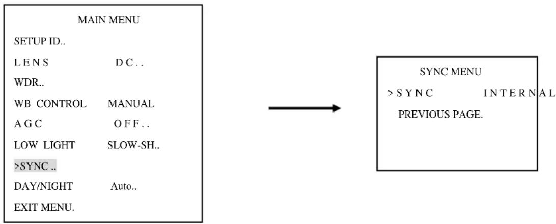
SYNC: INTERNAL/LINELOCK
SYNC-INTERNAL
Internal synchronization.
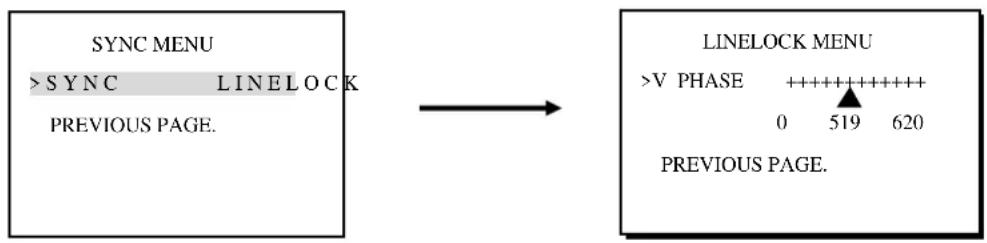
SYNC - LINELOCK
Phase adjustment may be necessary in multiple camera installations to prevent picture roll.
flowchart
graph LR
    A["SYNC MENU"] --> B["LINELOCK"]
    B --> C["PREVIOUS PAGE."]
    D["LINELOCK MENU"] --> E[">V PHASE ++++++ 0 519 620"]
    D --> F["PREVIOUS PAGE."]
V.PHASE: 0\~620
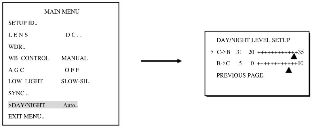
4.8 Day/Night
Auto/COLOR/B/W
flowchart
graph LR
    A["MAIN MENU"] --> B["SETUP ID.."]
    B --> C["L E N S D C .."]
    C --> D["WDR.."]
    D --> E["WB CONTROL MANUAL"]
    E --> F["A G C O F F"]
    F --> G["LOW LIGHT SLOW-SH.."]
    G --> H["SYNC .."]
    H --> I[">DAY/NIGHT Auto.."]
    I --> J["EXIT MENU.."]

    K["DAY/NIGHT LEVEL SETUP"] --> L["> C->B 31 20 ++++++++++35"]
    L --> M["B->C 5 0 ++++++++++10"]
    M --> N["PREVIOUS PAGE."]
DAY/NIGHT: Auto. For automatic switch between day and night mode.
C->B 20\~35
B->C 0\~10
PREVIOUS PAGE: Press SET button and you can return to the previous page.
DAY/NIGHT: Color. To keep color image at all time.
DAY/NIGHT: B/W. To keep Black and White image at all time.
4.9 Exit Menu
flowchart
graph LR
    A["MAIN MENU"] --> B["SETUP ID.."]
    A --> C["L E N S D C .."]
    A --> D["WDR.."]
    A --> E["WB CONTROL MANUAL"]
    A --> F["A G C O F F"]
    A --> G["LOW LIGHT SLOW-SH.."]
    A --> H["SYNC .."]
    A --> I["DAY/NIGHT Auto.."]
    A --> J[">EXIT MENU.."]

    K["SAVE RESTORE EXIT"] --> L[">EXIT NO CHANGE."]
    K --> M["SAVE NEW AND EXIT."]
    K --> N["RESTORE FACTORY SETTINGS."]
    K --> O["SW REV: 3.4"]
    K --> P["FW REV: 2.5-4.0.42"]
    K --> Q["PREVIOUS PAGE."]
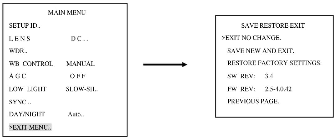
EXIT NO CHANGE: press enter and you can exit this page without saving the change you have made.
SAVE NEW AND EXIT: press enter to exit and the changes you have made will be saved.
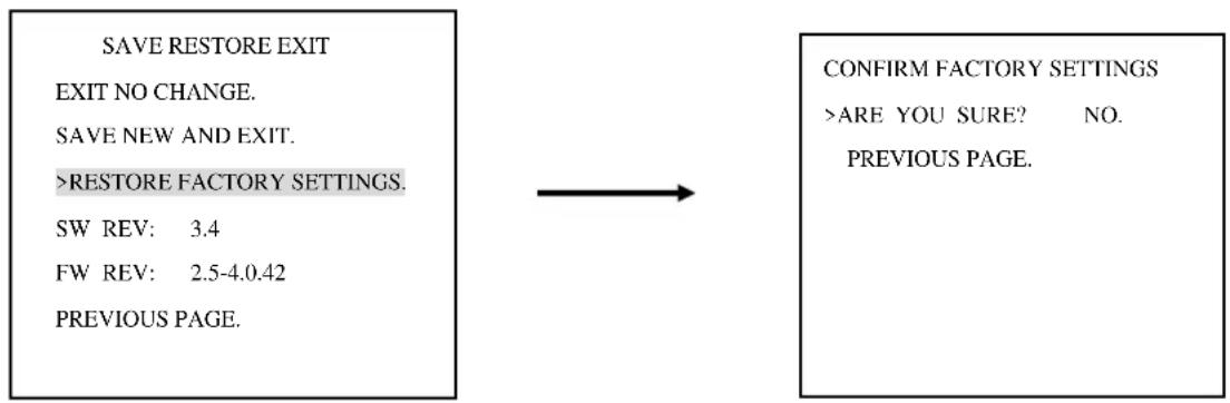
SAVE RESTORE EXIT: RESTORE FACTORY SETTING
flowchart
graph LR
    A["SAVE RESTORE EXIT\nEXIT NO CHANGE.\nSAVE NEW AND EXIT.\n>RESTORE FACTORY SETTINGS.\nSW REV: 3.4\nFW REV: 2.5-4.0.42\nPREVIOUS PAGE."] --> B["CONFIRM FACTORY SETTINGS\n>ARE YOU SURE? NO.\nPREVIOUS PAGE."]
RESTORE FACTORY SETTING: you will be asked “Are you sure?” before you restore all settings to factory values. Select “YES” to confirm.
SW REV: indicating software version.
FW REV.: indicating firmware version.
PREVIOUS PAGE: Press SET button and you can return to the previous page.
EverFocus Electronics Corp.
Head Office:
12F, No.79 Sec. 1 Shin-Tai Wu Road,
Hsi-Chih, Taipei, Taiwan
TEL: +886-2-26982334
FAX: +886-2-26982380
www.everfocus.com.tw
USA L.A. Office:
1801 Highland Ave. Unit A
Duarte, CA 91010, U.S.A.
TEL: +1-626-844-8888
FAX: +1-626-844-8838
www.everfocus.com
USA N.Y. Office:
415 Oser Avenue Unit S
Hauppauge, NY 11788
TEL: 631-436-5070
FAX: 631-436-5027
www.everfocus.com
Europe Office:
D-46446 Emmerich, Germany
TEL: +49(0)-2822-9394-0
FAX: +49(0)-2822-9394-95
www.everfocus.de
China Office:
Room B-05D-1, KESHI PLAZA, Shangdi
Information Industry Base,
Haidian District, Beijing China 100085
TEL: +86-10-62973336/37/38/39
FAX: +86-10-62971423
www.everfocus.com.cn
Japan Office:
1809 WBG MARIBU East 18F,
2-6 Nakase.Mihama-ku.
Chiba city 261-7118, Japan
TEL: +81-43-212-8188
FAX: +81-43-297-0081
www.everfocus.co.jp
Your EverFocus product is designed and manufactured with high quality materials and components which can be recycled and reused.
This symbol means that electrical and electronic equipment, at their end-of-life, should be disposed of separately from your household waste.
Please, dispose of this equipment at your local community waste collection/recycling centre.
In the European Union there are separate collection systems for used electrical and electronic product.
Please, help us to conserve the environment we live in!
- EVERFOCUS
- PRECAUTIONS
- TABLE OF CONTENTS
- PRODUCT OVERVIEW....3
- INSTALLATION....8
- HOW TO CONTROL OSD MENU....15
- MAIN MENU 17
- PRODUCT OVERVIEW
- Main Features
- Package Contents
- OPTIONAL ACCESSORIES
- Dimensions
- Hardware Overview
- INSTALLATION
- Simple Steps:
- Detail Installation Steps:
- Instruction for rotating the camera mounting
- Mounting Cameras on the Ceiling/Wall
- Conduit cable and Connect Power and Video
- Adjust Lens zoom and focus and View
- HOW TO CONTROL OSD MENU
- Where is OSD Controller
- General Operation Instruction
- Press the SET button for 3 seconds
- Using the cursor button
- Switch to sub-menu screens
- NOTE:
- Return to previous page
- Close the menu screen
- MAIN MENU
- Setup ID
- DISPLAY ID: ON/OFF.
- Lens
- WDR (Wide Dynamic Range)
- WDR BIAS: MIN -20 \~ 20 MAX
- WB Control
- ATW/AWB/MANUAL
- WB CONTROL: ATW
- WB CONTROL: MANUAL
- AGC
- Low Light
- SLOW SH../B&W SS/GAIN
- SYNC
- SYNC: INTERNAL/LINELOCK
- SYNC-INTERNAL
- SYNC - LINELOCK
- Day/Night
- Auto/COLOR/B/W
- Exit Menu
- SAVE RESTORE EXIT: RESTORE FACTORY SETTING
- EverFocus Electronics Corp.
- Head Office:
- USA L.A. Office:
- USA N.Y. Office:
- Europe Office:
- China Office:
- Japan Office:
Brand : EverFocus
Model : EHD650
Category : Security Camera