BCS260 - Brush cutter Sanli - Free user manual and instructions
Find the device manual for free BCS260 Sanli in PDF.

User questions about BCS260 Sanli
0 question about this device. Answer the ones you know or ask your own.
Ask a new question about this device
Download the instructions for your Brush cutter in PDF format for free! Find your manual BCS260 - Sanli and take your electronic device back in hand. On this page are published all the documents necessary for the use of your device. BCS260 by Sanli.
USER MANUAL BCS260 Sanli
Please read this instruction manual carefully before operating your new Sanli Brushcutter.
Congratulations on choosing a Sanli brushcutter.
Thank you for purchasing a Sanli 2-stroke brushcutter. We are sure that you'll enjoy many years of trouble-free performance, plus you have the reassurance of a 12 month warranty.
Inside this guide you will find out all you need to know to correctly operate your new Sanli Brushcutter. To ensure that you use your new brushcutter responsibly and get the best results possible, please read all of the safety and operating instructions carefully.
If after reading this user guide you have any questions on usage, safety, or any other issue, please call our Customer Help Line on 1800 466 068.
Contents
Sanli Brushcutter features....3&4
Tips on brushcutter safety. 5
Attaching the handle 6
Attaching the safety guard 6
Attaching the trimmer head 7
Replacing trimmer line - straight shaft 8
Replacing trimmer line - bent shaft 10
Starting your brushcutter 11
Using your accessories. 12
Technical specifications 13
Fast trouble shooting.... 14
Basic maintenance made easy 15
Contact Sanli Australia....16
Sanli products are monitored and enhanced on an on-going basis to comply with changing technical standards and requirements. As a result, Sanli reserves the right to alter design and specifications at any time without prior notice.
Straight shaft brushcutter features.
| 1 Spark Plug |
| 2 Choke Lever |
| 3 Air Filter |
| 4 Fuel Tank |
| 5 Ignition Switch |
| 6 Throttle Control |
| 7 Shoulder Strap Mount |
| 8 Shoulder Strap |
| 9 Handle |
| 10 Line trimmer Head |
| 11 Brushcutter Blade |
| 12 Fuel Mixing Bottle |
| 13 Tool Kit |
| 14 Safety Guard |
| 15 Guard fixing components |
| 16 Gear Head |

Bent shaft brushcutter features.
| 1 Spark Plug |
| 2 Choke Lever |
| 3 Air Filter |
| 4 Fuel Tank |
| 5 Ignition Switch |
| 6 Throttle Control |
| 7 Fuel Mixing Bottle |
| 8 Tool Kit |
| 9 Ergonomic Handle |
| 10 Sliding Sleeve |
| 11 Spark plug and gasket set |
| 12 Safety Guard |
| 13 Line Trimmer Head |
| 14 Bent Shaft |
| 15 Gear Head |

Tips on brushcutter safety.
WARNING! The information contained within this safety section is extremely important. Personal injury to the user and to others may result if this section is not read and acted upon at all times.
- Before starting your brushcutter inspect it carefully to ensure that there are no loose parts and that it is in good working order.
- Be sure of your footing. Always walk, never run, when operating the brushcutter.
- Clear the area of any stones, sticks, wire and debris before beginning, and always ensure that you operate your brushcutter a safe distance away (over 14 metres) from adults, children and animals.
- Keep hands, feet and clothing away from the brushcutter's moving parts, and always wear appropriate footwear (avoid sandals or open shoes).
- Never put your hands or feet underneath the guard of the brushcutter while the engine is running.
- Be aware that the machine's exhaust area and other parts of the brushcutter get very hot during, and right after use.
- Turn off the engine and disconnect the spark plug cap before cleaning, transporting or making adjustments.
- We recommend you avoid trimming when it is raining, or after nightfall.
- Do not fill the tank, or start the brushcutter indoors, or in a poorly ventilated area, as exhaust gases contain poisonous substances and petrol fumes are flammable and dangerous.
- Never open the fuel filler cap, or fill the tank, if the engine is still hot after use. And please ensure that you securely tighten the petrol cap after filling.
- Do not transport the brushcutter in a vehicle if there is any petrol in the tank.
- Store fuel and oil in a cool well-ventilated place, away from direct sunlight and not near gas cylinders or hot water heater systems.
- Do not smoke when filling the fuel tank, using the machine, or when petrol is in the immediate area. And never use or store the brushcutter near a naked flame.
- Sanli recommends that you wear ear protectors, safety goggles and safety boots when using a brushcutter.
- All servicing and repair work under warranty must be carried out by an Authorised Sanli Dealer, otherwise the 12 month warranty may be void.
Attaching the handle - straight shaft.
Place the upper ergonomic handle in the desired position, (Figure 1) then while holding the lateral handle underneath in position insert the screws and tighten with the allen key provided.
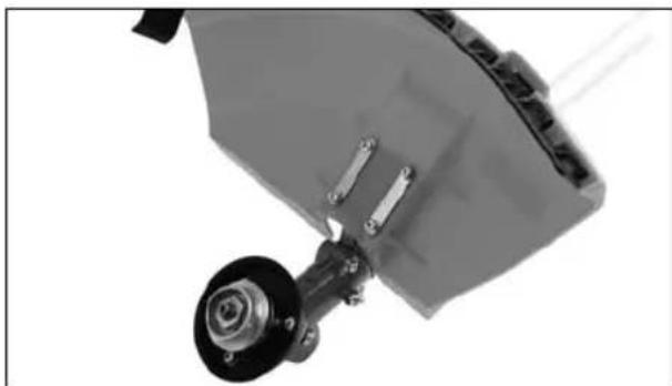
Attaching the safety guard - straight shaft.
While placing the brushcutter on its back place the guard as shown in (Figure 2) and locate the screws through the tension plates as indicated and tighten screws.

natural_image
Close-up of a mechanical device with a black ring and metal rod, no visible text or symbolsFigure 1.
natural_image
Close-up of a mechanical component with a metallic bracket and mounting base (no visible text or symbols)Figure 2.
Attaching the handle - bent shaft.
Place the upper ergonomic handle (Figure 3) over the sliding sleeve in the desired position, then while holding the bottom plate in place underneath insert the screws and tighten with the allen key provided.

natural_image
Close-up of a black metal clamp device with attached lever and mounting bracket (no visible text or symbols)Figure 3.
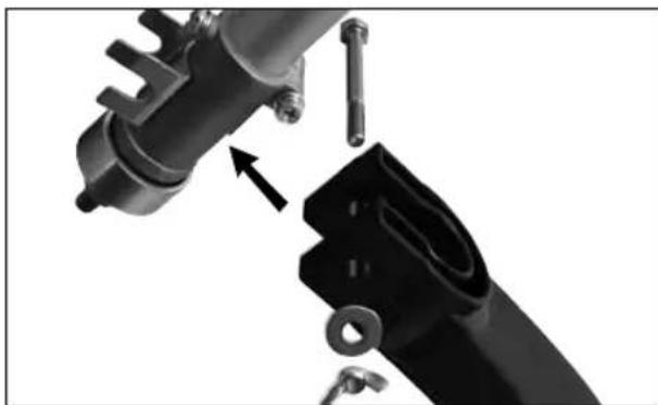
Attaching the safety guard - bent shaft.
While placing the brushcutter on its back, clip the guard onto the shaft lining the holes up with the guides see (Figure 4) then locate the bolt through the guard and guide plate as indicated. Place the washer over the bolt and tighten wing nut.
natural_image
Close-up of mechanical components with a directional arrow indicating assembly or movement (no visible text or symbols)Figure 4.
Attaching the trimmer head - straight shaft.
Insert the allen key provided into the hole on the gear head to stop it from rotating. Remove the nut, tension washer and brass ring as shipped and put in a safe place. These parts are required when fi tting the cutting blade which is supplied with this unit.

natural_image
Close-up of a mechanical assembly with a central bolted component and mounting bolts (no visible text or symbols)Figure 5.
Insert the allen key provided into the hole on the gear head to stop it from rotating. Then wind the trimmer head anti-clockwise onto the head see (Figure 6).

natural_image
Close-up of hands installing or adjusting a mechanical component with a black circular component (no visible text or symbols)Figure 6.
Attaching the trimmer head - bent shaft.
Insert the allen key provided into the hole on the gear head to stop it from rotating. Then wind the trimmer head clockwise onto the head (Figure 7).

natural_image
Close-up of hands adjusting a black mechanical component with a string (no visible text or symbols)Figure 7.
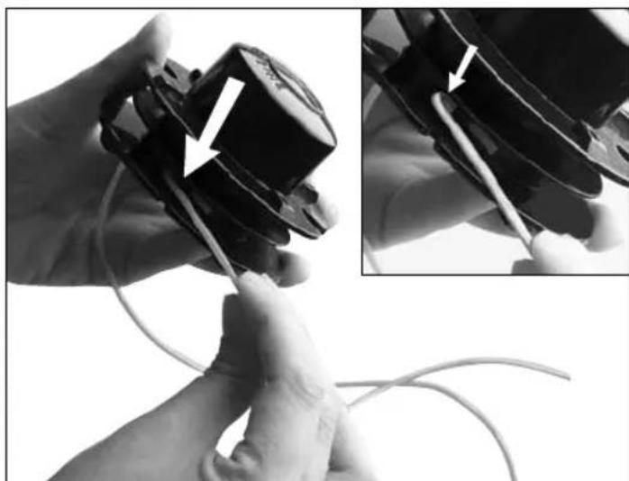
Replacing trimmer line - straight shaft.
Locate and depress the two retaining clips holding the lid in place see (Figure 8) and remove line spool.

natural_image
Hand holding a black cylindrical device with a cable inserted, showing a white arrow pointing to the left side (no text or symbols visible)Figure 8.
Take approximately 4-5 metres of 2.0-2.4mm diameter trimmer line and cut in half. At one end of each piece fold back about 10mm making a hook. Thread both hooks though hole indicated in (Figure 9) on either side of spool.
natural_image
Close-up of hands holding a small electronic device with wires, showing a close-up of the component (no text or symbols visible)Figure 9.
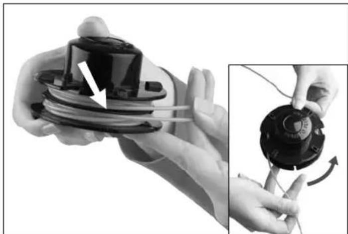
Wind both lines anti-clockwise on both sides of spool ensuring that both lines remain in their respective channels see (Figure 10).
natural_image
Close-up of hands holding a spool with a black plastic component, alongside a close-up of the mechanical component being adjusted (no text or symbols visible)Figure 10.
Replacing trimmer line - straight shaft continued.
In order to stop the line from unravelling, slip each end into the lugs on the bottom edge of the spool see (Figure 11).

natural_image
Close-up of a hand holding a black mechanical component with wires, no visible text or symbolsFigure 11.
Insert ends of lines through holes in side of spool casing and place the spool over the spring and into the casing see (Figure 12).
When in position pull the ends further out of the casing.

natural_image
Close-up of hands holding a black plastic component with coiled wires and a central cylindrical housing, no visible text or symbols.Figure 12.
Then replace the securing lid until it clicks into place see (Figure 13).
Return trimmer head to the gear head as in (Figure 6).

natural_image
Close-up of hands holding a black circular device with a white arrow pointing to a component (no text or symbols visible)Figure 13.
Replacing trimmer line - bent shaft.
Take approximately 4-5 metres of 2.0-2.4mm diameter trimmer, fold in half to make a loop. Hold the spool as shown in (Figure 14) and hook the loop onto the divider plate as shown and wind the line, one on either side of the divider plate.

natural_image
Close-up of hands adjusting a mechanical component with a finger (no visible text or symbols)Figure 14.
Wind both lines clockwise on both sides of spool ensuring that both lines remain in their respective channels see (Figure 15).

natural_image
Close-up of hands using a mechanical tool to press or adjust a circular component, no visible text or symbols.Figure 15.
In order to stop the line from unravelling, slip each end into the lugs on the bottom edge of the spool see (Figure 16).

natural_image
Close-up of hands manipulating a coiled wire with an arrow indicating motion (no text or symbols)Figure 16.
Insert ends of lines through holes in side of spool casing and place the spool into the centre of the casing see (Figure 17).

natural_image
Close-up of hands assembling a black mechanical component with wires, no visible text or symbolsFigure 17.
When in position pull the ends further out of the casing.
Then return the lid, click into place and return to hub.
Starting your brushcutter.
Before operating your brushcutter, mix 25 parts of regular unleaded petrol to 1 part 2-stroke oil (25:1). Do not overfill the tank as this can risk fuel spilling on hot parts when in use.
Slide the ignition switch forward away from the STOP position (Figure 18).

natural_image
Close-up of a hand holding a black handheld device with a white arrow indicating motion (no text or symbols visible)Figure 18.
Press primer bulb three or four times until a flow of fuel is visible inside the fuel line (Figure 19).

natural_image
Close-up of a hand adjusting a camera module with a white arrow pointing to the button (no visible text or symbols)Figure 19.
Set choke lever into closed position if starting from cold (Figure 20).
Pull the starter cord until the brushcutter starts (or sounds like it wants to start) then return choke to | | open position.
After it starts, allow the engine to warm up for at least 20 to 30 seconds.
For warm restarts, do not prime, just pull the cord and it will start after one or more pulls.

natural_image
Close-up of a hand pressing a black mechanical component with a white arrow pointing to it, no visible text or symbols.Figure 20.
To stop the engine, simply move the ignition switch back to the STOP position (Figure 21).

natural_image
Close-up of a hand holding a black handheld electric shaver with a handle, showing mechanical components and a hand adjusting the lever (no text or symbols visible)Figure 21.
Using your accessories - straight shaft.
The shoulder strap see (Figure 22) can be adjusted in length for the convenience of the operator and hooks onto the eyelet on the shaft. Please note the hip guard should be placed between the body and the brushcutter.
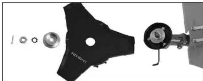
Attaching the cutting blade
(straight shaft model only).
When heavy duty cutting is required utilise the cutting blade (Figure 23). Remove the trimmer bump head (refer to figure 5) and rotate opposite direction. Then place the cutting blade as shown and tighten in anti-clockwise direction.
Order of components to attach the cutter blade (Figure 24).

natural_image
Person wearing a black outfit and holding a handheld device with a charging plug (no visible text or symbols)Figure 22.

natural_image
Close-up of hands using a wrench to adjust a mechanical component (no visible text or symbols)Figure 23.
natural_image
Exploded view of a mechanical component with multiple parts and a central hole (no visible text or symbols)Figure 24.
Technical specifications.
| Model number BCS260 BCB260 | ||
| Drive train | Auto clutch, spiralbevel gear, rigid shaft | Auto clutch, spiralbevel gear, fl exible shaft |
| Reduction gear ratio 1:1 1:1 | ||
| Engine type 2-stroke vertical piston valve 2-stroke vertical piston valve | ||
| Engine model 1E34F petrol engine 1E34F petrol engine | ||
| Fuel mix 25:1 unleaded petrol to 2-stroke oil 25:1 unleaded petrol to 2-stroke oil | ||
| Engine idling speed | 2,800rpm | 2,800rpm |
| Engine power | 0.71kW@6,000rpm | 0.71kW@6,000rpm |
| Spark plug type | NGK BPMR7A | NGK BPMR7A |
| Spark plug gap | 0.6 to 0.7 mm | 0.6 to 0.7 mm |
| Length of main pipe | 1502 mm | 1520 mm |
| Length of drive shaft | 1375 mm | 1375 mm |
| Fuel tank capacity | 600ml | 600ml |
| Length of line out of hub | 100-150 mm | 100-150 mm |
| Noise level | 79dBA | 79dBA |
| Dry weight | 4.4 Kg | 4.4kg |
| Warranty | 1 year domestic warranty | 1 year domestic warranty |
Fast trouble shooting.
Often, a depleted, loose, or dirty spark plug is responsible for a brush cutter not being able to start, but there can be a number of other reasons. Refer below to the list of potential problems you may encounter, along with suggested remedies.
For servicing and all warranty work, contact your local Authorised Sanli Dealer.
| Problem Likely cause Suggested remedy | ||
| Engine does not start | Out, or almost out, of fuelSpark plug dirtySpark plug not connectedFuel older than 3 monthsWater in the fuel tank | Fill tank with fresh 2 stroke fuel (25:1)Clean or replace with a new spark plugPress firmly on the terminal coverDrain stale fuel and replace with fresh 2 stroke fuelContact an authorised Sanli dealer |
| Engine stops often | Blocked fuel supplyFuel cap is not ventingIncorrect type of fuel | Ensure the fuel line is not pinched or blockedEnsure vent hole in the fuel tank cap is clearDrain tank and fi ll with 2 stroke fuel (25:1) |
| Engine loses power | Dirty air cleaner fi lterBlocked fuel cap vent holes | Clean or replace with a new Sanli air-fi lterEnsure vent hole in the fuel tank cap is clear |
| Too much vibration | Loose line trimmer headDamaged cutting blade(straight shaft model only) | Check and tighten bolts and nuts accordinglyReplace cutting blade |
Basic maintenance made easy.
WARNING! If the brush cutter is not serviced correctly, you could void warranty and reduce its ability to operate effectively.
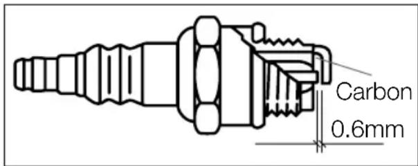
1. Spark plug.
Wait until the engine has cooled before disconnecting the spark plug cover and then removing the spark plug with the box spanner supplied. If it is dirty, you can clean the plug with a wire brush.
The applicable spark plug for this machine is the NGK BPMR7A. For optimum results we advise you to replace the spark plug after 20 hours of use.
When refi tting the spark plug take care not to over-tighten. If adjusting yourself, note that the spark plug gap must be set initially to 0.6 but after the machine has been used for some time, regulate the gap to 0.7 mm.
2. Air fi Iter.
Figure 25.

Ensure that the engine is cool, remove the air fi Iter cover and then take out the air fi Iter element, see (Figure 25). Put the cover back on the housing immediately to prevent any objects falling into the air intake.
Carefully brush off any excess dirt particles, or clean fi Iter element using lukewarm soapy water. When cleaning with water, rinse thoroughly and allow to dry before replacing air fi Iter element.
3. Storing petrol and oil.
WARNING! Petrol is highly fl ammable so extreme caution must be taken. Always store petrol in approved containers and ensure petrol is less than three months old.

SANLI
Call the Sanli Customer Service Desk on 1800 466 068
Email: support@sanli.com.au Web: www.sanli.com.au
Head Office: 4/100 Belmore Road, Riverwood, NSW 2210