
ProCurve 4100gl - Network switch HP - Free user manual and instructions
Find the device manual for free ProCurve 4100gl HP in PDF.


| Product Type | HP ProCurve Series 4100gl Network Switch |
| Form Factor | Rackmount (19-inch), horizontal surface mount, or wall mount |
| Chassis Slots | 4-slot (4104gl, 4140gl, 4148gl) or 8-slot (4108gl, 4160gl) |
| Switching Fabric | 36.6 Gbps |
| Supported Modules | 24-port 10/100-TX, 6-port 100/1000-T, 3-port Gigabit Transceiver, 6-port mini-GBIC, 20-port Gig-T with 2 mini-GBIC |
| MAC Address Table | 8000 addresses, configurable aging |
| VLAN Support | Up to 30 IEEE 802.1Q VLANs |
| Spanning Tree Protocol | Supported (IEEE 802.1D) |
| Port Features | Auto-MDIX on 10/100 ports; Auto MDI/MDI-X on 100/1000-T; full duplex on all ports; hot-swappable modules and transceivers |
| Management Interfaces | Console (CLI/menu via serial or telnet), Web browser, SNMP (HP ProCurve Manager) |
| Power Supply | Auto-sensing 100-127/200-240 VAC, 50/60 Hz; no power switch; optional redundant hot-swappable power supply |
| Cooling | Internal fans; replaceable; front-to-back airflow |
| Operating Temperature | 0°C to 55°C (32°F to 131°F) |
| Safety & Emissions | FCC Class A, CE, VCCI Class A, UL/EN 60950 (IEC 950) |
| Dimensions (4-slot chassis) | Approx. 17.3 x 14.5 x 3.5 in (44 x 37 x 8.9 cm) ~2U |
| Dimensions (8-slot chassis) | Approx. 17.3 x 17.3 x 6.9 in (44 x 44 x 17.5 cm) ~4U |
| Weight (empty chassis) | Approx. 20-35 lbs (9-16 kg) depending on configuration |
| Spare Parts & Reparability | User-replaceable modules, power supply, fans; no internal user-serviceable parts; contact HP authorized service for repairs |
| Warranty | See Customer Support/Warranty booklet; lifetime limited warranty for HP ProCurve switches |
Frequently Asked Questions - ProCurve 4100gl HP
User questions about ProCurve 4100gl HP
0 question about this device. Answer the ones you know or ask your own.
Ask a new question about this device
Download the instructions for your Network switch in PDF format for free! Find your manual ProCurve 4100gl - HP and take your electronic device back in hand. On this page are published all the documents necessary for the use of your device. ProCurve 4100gl by HP.
USER MANUAL ProCurve 4100gl HP
installation and getting started guide

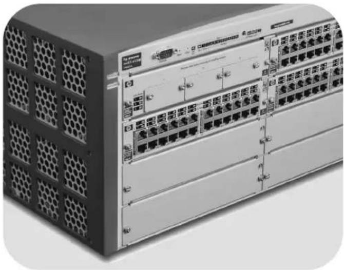
natural_image
Front view of a server rack unit with multiple Ethernet ports and hexagonal ventilation grilles (no visible text or labels)hp procurve series 4100gl switches
www.hp.com/go/hpprocurve
HP ProCurve Series 4100gl Switches
Installation and Getting Started Guide
© Copyright 2003 Hewlett-Packard Development Company, L.P. The information contained herein is subject to change without notice.
This document contains proprietary information, which is protected by copyright. No part of this document may be photocopied, reproduced, or translated into another language without the prior written consent of Hewlett-Packard.
Publication Number
5990-6048
November 2003
Applicable Products
HP ProCurve Switch 4108gl (J4865A)
HP ProCurve Switch 4108gl Bundle (J4861A)
HP ProCurve Switch 4104gl (J4887A)
HP ProCurve Switch 4140gl (J8151A)
IIP ProCurve Switch 4148gl (J4888A)
HP ProCurve Switch 4160gl (J8152A)
Disclaimer
HEWLETT-PACKARD COMPANY MAKES NO WARRANTY OF ANY KIND WITHI REGARD TO THIS MATERIAL, INCLUDING, BUT NOT LIMITED TO, THE IMPLIED WARRANTIES OF MERCHANTABILITY AND FITNESS FOR A PARTICULAR PURPOSE. Hewlett-Packard shall not be liable for errors contained herein or for incidental or consequential damages in connection with the furnishing, performance, or use of this material.
The only warranties for HP products and services are set forth in the express warranty statements accompanying such products and services. Nothing herein should be construed as constituting an additional warranty. HP shall not be liable for technical or editorial errors or omissions contained herein.
Hewlett-Packard assumes no responsibility for the use or reliability of its software on equipment that is not furnished by Hewlett-Packard.
Warranty
See the Customer Support/Warranty booklet included with the product.
A copy of the specific warranty terms applicable to your Hewlett-Packard products and replacement parts can be obtained from your IIP Sales and Service Office or authorized dealer.
Safety
Before installing and operating these products, please read the "Installation Precautions" in chapter 2, "Installing the Series 4100gl Switches", and the safety statements in appendix C, "Safety and Regulatory Statements".
Contents
1 Introducing the HP ProCurve Series 4100gl Switches
Front of the Switch 1-4
LEDs 1-5
LED Mode Select Button and Indicator LEDs 1-7
Console Port 1-8
Reset Button 1-8
Clear Button 1-8
Back of the Switch 1-9
Power Connector 1-9
Slot for Redundant Power Supply 1-9
Switch Features 1-10
2 Installing the Series 4100gl Switches
Included Parts 2-1
Installation Procedures 2-2
Summary 2-2
Installation Precautions 2-3
Installation Precautions (continued) 2-4
- Prepare the Installation Site 2-5
Cabling Infrastructure 2-5
Installation Location 2-6
-
Install Switch Modules 2-7
-
(Optional) Install Second Power Supply 2-9
-
Verify the Switch Passes Self Test ..... 2-11
LED Behavior: 2-12
- Mount the Switch 2-13
Rack or Cabinet Mounting 2-13
Horizontal Surface Mounting 2-16
Wall Mounting 2-17
-
Connect the Switch to a Power Source ..... 2-18
-
Connect the Network Devices ..... 2-18
-
(Optional) Connect a Console to the Switch ..... 2-19
Terminal Configuration 2-19
Direct Console Access 2-20
Telnet Console Access 2-20
Hot Swapping Switch Modules 2-21
Adding or Replacing Modules 2-21
Changing the Module Type 2-21
Example Network Topologies 2-22
Basic Connectivity 2-22
Use as an Edge Switch 2-23
Stacking the Switches 2-24
3 Getting Started With Switch Configuration
Recommended Minimal Configuration 3-1
Using the Switch Setup Screen 3-2
Where to Go From Here 3-4
Using the IP Address for Remote Switch Management 3-5
Starting a Telnet Session 3-5
Starting a Web Browser Session 3-5
4 Troubleshooting
Basic Troubleshooting Tips 4-1
Diagnosing with the LEDs 4-4
Proactive Networking 4-9
Hardware Diagnostic Tests 4-10
Testing the Switch by Resetting It 4-10
Checking the Switch LEDs 4-10
Checking Console Messages 4-10
Testing Twisted-Pair Cabling 4-11
Testing Switch-to-Device Network Communications 4-11
Testing End-to-End Network Communications 4-11
Restoring the Factory Default Configuration 4-12
Downloading New Code 4-13
HP Customer Support Services 4-13
Before Calling Support 4-13
A Specifications
Physical A-1
Electrical A-1
Environmental A-2
Acoustic A-3
Switch 4108gl and Bundle; 4160gl: A-3
Switch 4104gl, 4148gl, and 4140gl: A-3
Network Connectors A-3
Safety A-3
B Switch Ports and Network Cables
Switch Ports B-1
Twisted Pair ...... B-1
Fiber-Optic B-1
Cables B-2
Twisted-Pair Cable/Connector Pin-Outs B-3
Straight-Through Twisted-Pair Cable for
10 Mbps or 100 Mbps Network Connections ...... B-5
Cable Diagram B-5
Pin Assignments B-5
Crossover Twisted-Pair Cable for
10 Mbps or 100 Mbps Network Connection .... B-6
Cable Diagram B-6
Pin Assignments B-6
Straight-Through Twisted-Pair Cable for
1000 Mbps Network Connections B-7
Cable Diagram B-7
Pin Assignments B-7
C Safety and EMC Regulatory Statements
Safety Information C-1
Safety Information (China) C-7
EMC Regulatory Statements C-8
U.S.A. C-8
Canada C-8
Australia/New Zealand C-8
Japan C-8
Korea C-9
Taiwan C-9
Regulatory Model Identification Number C-9
Index
Introducing the HP ProCurve Series 4100gl Switches
The HP ProCurve Series 4100gl Switches include the Switch 4104gl and its bundle, the Switch 4148gl, and the Switch 4108gl and Switch 4108gl Bundle. They are multiport modular switches that can be used to build high-performance switched workgroup networks. These switches are store-and-forward devices that offer low latency for high-speed networking.
This chapter describes your HP Series 4100gl Switches including:
■ Front and back of the switches
■ Features
■ Switch operation overview
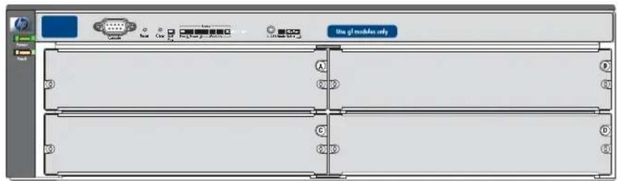
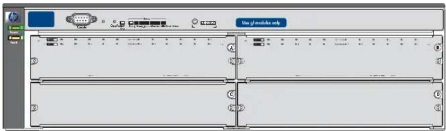
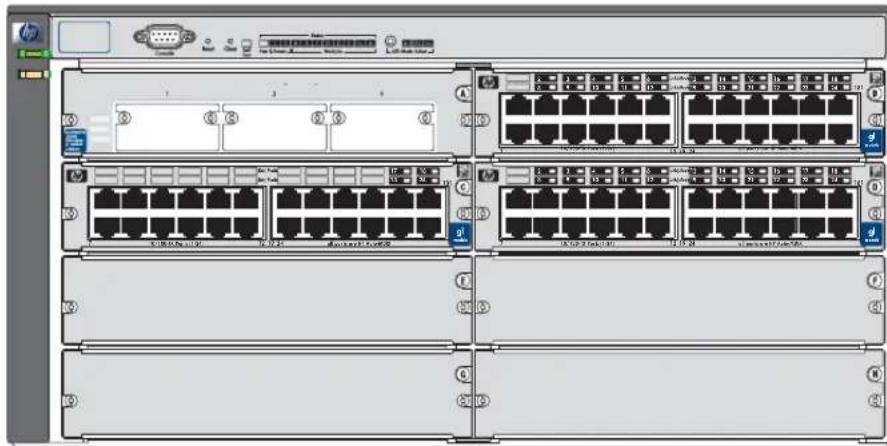
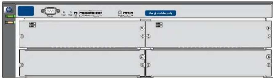
Switch 4104gl and Switch 4148gl. The Switch 4104gl is available as an open 4-slot chassis (J4887A) or as the Switch 4148gl (J4888A) with two 24-port 10/100-TX gl Modules pre-installed.
HP ProCurve Switch4104gl (J4887A)
HP ProCurve Switch 4148gl (J4888A) with two 10/100-TX gl Modules preinstalled
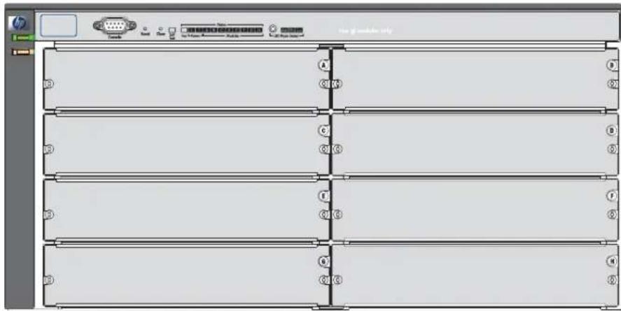
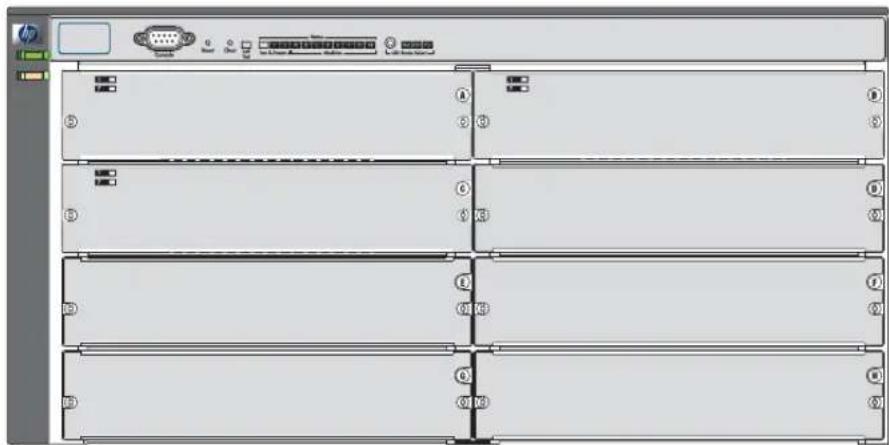
Switch 4108gl and Bundle. The Switch 4108gl is available as an open 8-slot chassis (J4865A) or as the Switch 4108gl Bundle (J4861A) with one 3-port Gigabit Transceiver gl Module and three 24-port 10/100-TX gl Modules pre-installed.
HP ProCurve Switch4108gl (J4865A)
HP ProCurve Switch 4108gl Bundle (J4861A)
with one Gigabit Transceiver gl Module and three 10/100-TX gl Modules preinstalled
Switch 4140gl. The Switch 4140gl is available as a four slot chassis (J8151A) with two 20-port Gig-T gl modules with 2 mini-GBIC Gig ports (J4908A) preinstalled.
Switch 4160gl. The Switch 4160gl (J8152A) is available as an eight slot chassis with three 20-port Gig-T gl modules with 2 mini-GBIC Gig ports (J4908A) preinstalled.
See “Switch Features” on page 1-10 for a list of the switch modules that you can install in the HP ProCurve Series 4100gl Switches (modules available when this manual was printed).
With these switches you can build a switched network infrastructure by connecting it to hubs, other switches, or routers, or you can connect computers, printers, and servers to this switch to provide dedicated bandwidth to those devices.
Front of the Switch
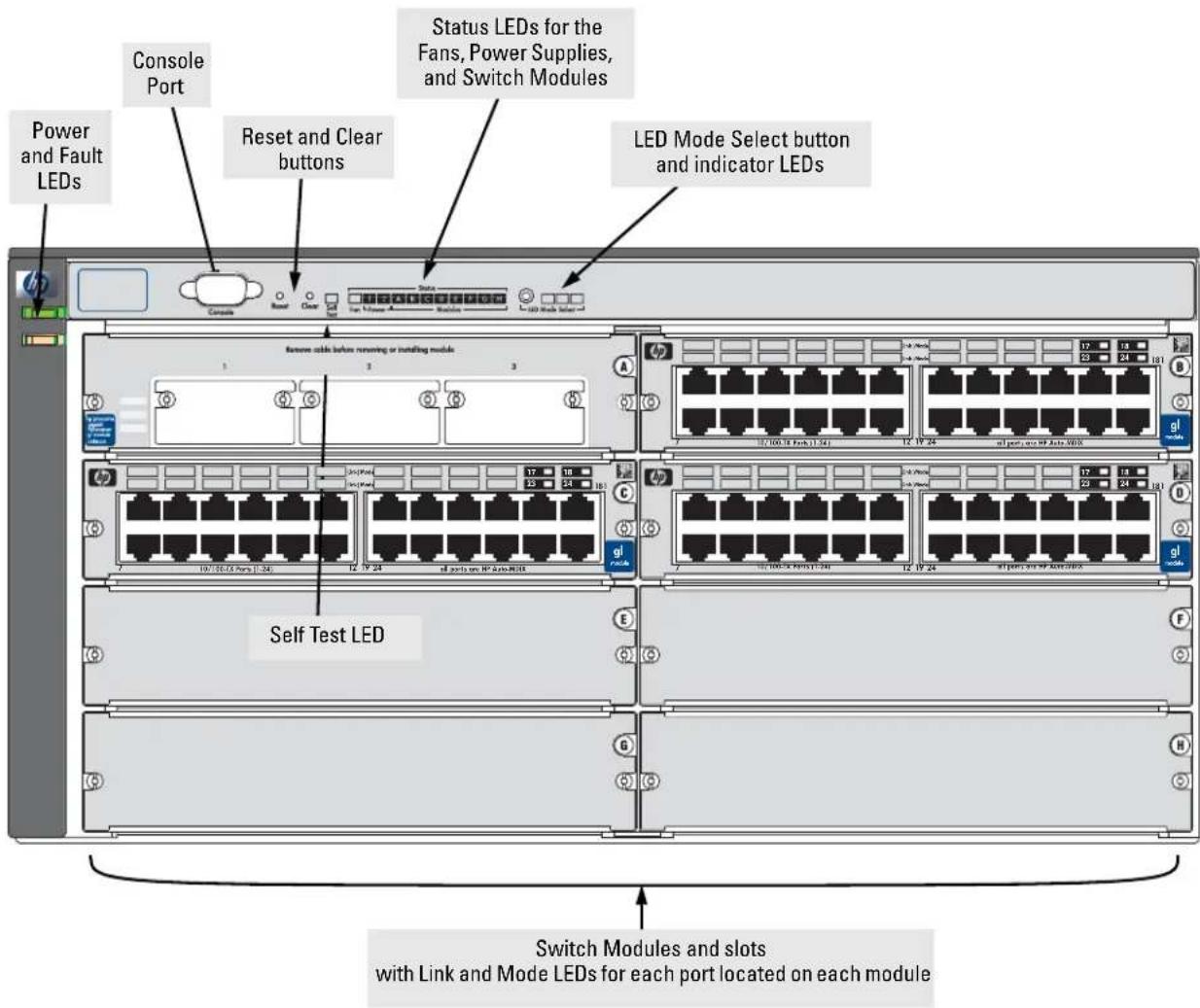
This illustration shows the 4108gl Bundle, but the labeling and descriptions apply to all of the HP ProCurve Series 4100gl switches.
LEDs
As described in the next two tables, there are LEDs on the switch chassis and on the switch modules that keep you informed of the status of the switch and the network connections.
Table 1-1. Switch Chassis LEDs
| LEDs State Meaning | ||
| Power (green) | On | The switch is receiving power. |
| Off | The switch is NOT receiving power. | |
| Fault (orange) | Off | The normal state; indicates that there are no fault conditions on the switch. |
| Flashing^† | A fault has occurred on the switch, one of the switch modules, a power supply, or a fan. The Status LED for the module or other device with the fault will flash simultaneously. | |
| On | On briefly at the beginning of switch self test after the switch is powered on or reset. If on for a prolonged time, the switch has encountered a fatal hardware failure, or has failed its self test. See chapter 4, “Troubleshooting” for more information. | |
| Self Test (green) | Off | The normal operational state; the switch is not undergoing self test. |
| On | The switch self test and initialization are in progress after you have power cycled or reset the switch. The switch is not operational until this LED goes off. The Self Test LED also comes on briefly when you “hot swap” a module into the switch and the module is automatically self tested. | |
| Flashing^† | A component of the switch has failed its self test. The Status LED for that component, for example a switch module, and the switch Fault LED will flash simultaneously. | |
| Status/Fan (green) | On | The cooling fans are operating normally. |
| Flashing^† | One or more of the cooling fans have failed. The switch Fault LED will be flashing simultaneously. | |
| Status/Power (green - numbers corresponding to the power supply positions) | On | A power supply is installed in the position in the back of the switch corresponding to the number, and the supply is plugged in to an active AC power source. As shipped, the switch has a single power supply in position 1. |
| Off | A power supply is not installed in the position corresponding to the number. | |
| Flashing^† | The power supply installed in the position corresponding to the number is not plugged in to an active AC power source, or has experienced a fault. The switch Fault LED will be flashing simultaneously. | |
| Status/Modules(green - letters corresponding to the switch module slots) | On | A module is installed in the switch module slot corresponding to the letter and the module is undergoing or has passed self test. This also occurs when you install a module when the switch is powered on ("hot swap"). |
| Off | A module is not installed in the switch module slot corresponding to the letter. | |
| Flashing^† | The module status LED flashes very briefly when a module is being hot swapped. If the LED flashes for a prolonged time, the module in the slot corresponding to the letter has failed self test or encountered some other fault condition. See chapter 4, "Troubleshooting" for a more information. | |
| LED Mode Select(3 green LEDs) | Act | Indicates the port Mode LEDs are displaying network activity information. |
| FDx | Indicates the port Mode LEDs are lit for ports that are in Full Duplex Mode. | |
| Max | Indicates the port Mode LEDs are lit for ports that are operating at their maximum possible link speed -- for any Gigabit-capable connection, that would be 1000 Mbps; for the 10/100-TX ports and 100-FX ports, that would be 100 Mbps. | |
| The flashing behavior is an on/off cycle once every 1.6 seconds, approximately. | ||
Table 1-2. Switch Module LEDs
The following LEDs are located on the modules themselves, one pair for each port.
| LED State Meaning | ||
| Link On | Off | Indicates the port is enabled and receiving a link beat signal (for the twisted-pair ports), or a strong enough light level (for the fiber-optic ports) from the connected device.One of these conditions exists:no active network cable is connected to the portthe port is not receiving link beat or sufficient lightthe port has been disabled through the switch console, the web browser interface, HP ProCurve Manager, or other network management tool.The port has failed self test. The switch Fault and Self Test LEDs, and appropriate module status LEDs will flash simultaneously. |
| Flashing^† | ||
| Mode | Depending on the mode selected, displays the following: network activity information, whether the port is configured for Full Duplex operation, maximum speed operation, or whether network errors are occurring on the port. See “LED Mode Select Button and Indicator LEDs” below for more information. | |
| ^†The flashing behavior is an on/off cycle once every 1.6 seconds, approximately. | ||
LED Mode Select Button and Indicator LEDs
To optimize the amount of information that can be displayed for each of the switch ports, the Series 4100gl Switches use a Mode LED for each port. The operation of this LED is controlled by the LED Mode Select button on the switch chassis, and the current setting is indicated by the mode indicator LEDs near the button. Press the button to change from one mode to the next.
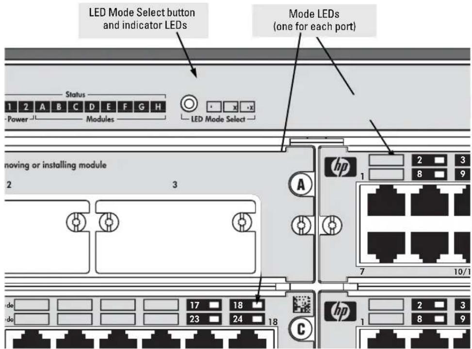
■ If the Activity Ad indicator LED is lit, each port Mode LED displays activity information for the port—it flickers as network traffic is received and transmitted through the port.
■ If the Full Duplex FDx indicator LED is lit, the port Mode LEDs light for those ports that are operating in full duplex.
- If the maximum speed Max indicator LED is lit, the port Mode LEDs light for those ports that are operating at their maximum possible link speed.
Console Port
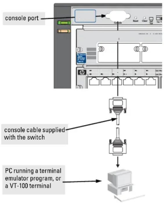
This port is used to connect a console to the switch by using the serial cable supplied with the switch. This connection is described under “Connecting a Console to the Switch” in chapter 2, “Installing the Series 4100gl Switches”. The console is a full-featured interface that can be used to configure, monitor, and troubleshoot the switch. It can be run on a PC emulating a VT-100 terminal, or on a standard VT-100 terminal.
Reset Button
This button is used to reset the switch while it is powered on. This action clears any temporary error conditions that may have occurred, executes the switch self test, and resets all network activity counters to zero. The counters are displayed in the switch console interface, the switch web browser interface, and through SNMP network management applications, such as IIP ProCurve Manager for Hubs & Switches.
Press the Reset button also after changing the module type that is installed in any of the switch module slots while the switch is powered on. In this case, the switch must be reset to initialize the new module type. See “Hot Swapping Switch Modules” on page 2-21.
Clear Button
This button is used for the following purposes:
- Deleting Passwords - When pressed by itself for at least one second, the Clear button deletes any switch console access passwords that you may have configured. Use this feature if you have misplaced the password and need console access.
This button is provided for your convenience, but its presence means that if you are concerned with the security of the switch configuration and operation, you should make sure the switch is installed in a secure location, such as a locked wiring closet.
- Restoring Factory Default Configuration - When pressed with the Reset button in a specific pattern, the Clear button clears any configuration changes you may have made through the switch console, the web browser interface, or SNMP management, and restores the factory default configuration to the switch. For the specific method to restore the factory default configuration, see “Restoring the Factory Default Configuration” in chapter 4, “Troubleshooting” of this manual.
Back of the Switch
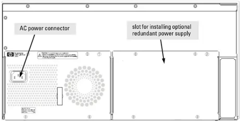
Power Connector
The Series 4100gl Switches do not have a power switch; they are powered on when connected to an active AC power source. The switches automatically adjust to any voltage between 100-127 and 200-240 volts and either 50 or 60 Hz. There are no voltage range settings required.
Slot for Redundant Power Supply
A second, load-sharing redundant power supply (HP ProCurve Switch gl/xl RPS, HP J4839A) can be installed in the back of the Series 4100gl switches. To provide true redundancy, this second power supply should be connected to a different AC power source from the other supply. Then, if one AC power source fails, the switch will continue to run.
Caution
The switch power supplies are hot swappable, but, as indicated by the caution statement on the power supply, it must be disconnected from AC power before being installed or removed.

Caution:
- Refer to the installation guide for proper power cord selection.
- Disconnect AC power from this power supply BEFORE installing or removing the supply. Otherwise, damage to the equipment may result.
Because the switch can run on a single supply, removing a redundant supply will not interrupt switch operation.
Switch Features
The features of the Series 4100gl Switches include:
4 or 8 slots for installing any of the available Switch gl Modules.
Supported Modules: As of this printing, the supported gl modules includes:
• 24-port 10/100-TX gl Module (J4862A)
• 6-port 100/1000-T gl Module (J4863A)
- 3-port Gigabit Transceiver gl Module (J4864A) -- into which you can install any of five different transceiver types including Gigabit-SX, Gigabit-LX, 100/1000Base-T, Gigabit Stacking, and 100Base-FX
- 6-port mini-GBIC gl Module (J4893A) -- into which you can install the supported mini-GBICs, the HP Gigabit-SX LC mini-GBIC (J4858A) and the HP Gigabit-LX LC mini-GBIC (J4859A)
• 20-port Gig-T gl module with 2 mini-GBIC Gig ports (J4908A)
The Switch 4108gl Bundle has one Gigabit Transceiver gl Module and three 10/100-TX gl Modules preinstalled, and the Switch 4148gl has two 10/100-TX gl Modules preinstalled.
the modules can be installed in any order and in any combination and can be “hot swapped”.
the supported HP ProCurve transceivers can be hot swapped into the Gigabit Transceiver gl Module.
the supported mini-GBICs can be hot swapped into the mini-GBIC gl Module.
high performance -- 36.6 Gbps switching fabric.
plug-and-play networking—all ports are enabled—just connect the network cables to active network devices and your switched network is operational.
automatic learning of the network addresses in the switch's 8000-address forwarding table, with configurable address aging value.
full-duplex operation available on all ports.
Switch Features continued on the next page.
easy management of the switch through several available interfaces:
- web browser interface—an easy to use built-in graphical interface that can be accessed from common web browsers.
- console interface—a full featured, easy to use, VT-100 terminal interface for out-of-band switch management, or for telnet access to the switch. The console includes complete switch management through a command line interface (CLI) and a slightly reduced feature set accessible through an intuitive menu interface.
- HP ProCurve Manager for Hubs & Switches—an SNMP-based graphical interface that is used to manage your entire network, included with your new switch.
- Supported by HP OpenView ProCurve Network Manager—an HP OpenView application that accurately displays your switch on network maps and provides a graphical interface for configuring and monitoring your switch.
support for the Spanning Tree Protocol to eliminate network loops.
support for up to 30 IEEE 802.1Q-compliant VLANs so you can divide the attached end nodes into logical groupings that fit your business needs.
support for many advanced features to enhance network performance—for a description, see the Management and Configuration Guide that is on the documentation CD-ROM that is included with your switch.
— This page is intentionally unused. —
Installing the Series 4100gl Switches
The HP Series 4100gl Switches are easily installed. They come with an accessory kit that includes the brackets for mounting the switch in a standard 19-inch telco rack, in an equipment cabinet, or on a wall. The switches have rubber feet already attached so they can be securely located on a horizontal surface.
This chapter shows you how to install the Series 4100gl Switches.
Included Parts
The Series 4100gl Switches and Bundles have the following components shipped with them:
HP ProCurve Series 4100gl Switches Installation Guide (5990-3005), this manual
HP ProCurve Series 4100gl Switches Documentation CD ROM (contains a PDF file copies of the HP ProCurve Series 4100gl Switches Management and Configuration Guide, this Installation and Getting Started Guide, and other related documentation)
HP ProCurve Manager for Hubs & Switches - CD ROM and booklet
Customer Support/Warranty booklet
Accessory kit (5065-6521 for the 8-slot Switch 4108gl and Switch 4108gl Bundle; 5064-9943 for the 4-slot Switch 4104gl and Switch 4148gl):
- two mounting brackets
- six or four 10 mm M4 screws to attach the mounting brackets to the switch
• four 5/8-inch number 12-24 screws to attach the switch to a rack
□ Console cable
Power cord, one of the following:
| Australia/New Zealand | 8120-6803 |
| China 8120-8377 United Kingdom/ | |
| Continental Europe | 8120-6802 |
| Denmark | 8120-6806 |
| Japan 8121-0606 | |
Switzerland 8120-6807
Hong Kong/Singapore 8120-8709 United States/Canada/Mexico 8121-0605
Installation Procedures
Summary
Follow these easy steps to install your switch. The rest of this chapter provides details on these steps.
- Prepare the installation site (page 2-5). Ensure the physical environment into which you will be installing the switch is properly prepared including having the correct network cabling ready to connect to the switch, and having a good location for the switch. Please see page 2-3 for some installation precautions.
- Install switch modules (page 2-7). The Series 4100gl Switches have four or eight universal slots for installing any of the HP ProCurve Switch gl modules. The Switch 4108gl Bundle has three 24-port 10/100-TX gl Modules and one 3-port Transceiver gl Module preinstalled, and the Switch 4148gl has two 24-port 10/100-TX gl Modules preinstalled. Depending on where you will install your Series 4100gl switch, it may be easier to install the modules first. The modules are “hot swappable” though, so they can also be installed and removed after the switch is powered on.
Note: Make sure you use only HP ProCurve Switch gl Modules in your Series 4100gl Switches.
-
(Optional) Install second power supply (page 2-9). The Series 4100gl Switches have a slot in the back for installing a second, load-sharing power supply. If you have purchased this supply, it may be easier to install it before mounting the switch.
-
Verify that the switch passes self test (page 2-11). This is a simple process of plugging the switch into a power source and observing that the LEDs on the switch's front panel and on the modules show correct operation.
-
Mount the switch (page 2-13). The Series 4100gl Switches can be mounted in a 19-inch telco rack, in an equipment cabinet, on a wall, or on a horizontal surface. Note that there are some limitations to the wall mounting orientations that are supported. Please see the installation details for more information.
-
Connect power to the switch (page 2-18). Once the switch is mounted, plug it in to the nearby main power source.
-
Connect the network devices (page 2-18). Using the appropriate network cables, connect other switches, hubs, routers, computers, servers, printers, and other network devices to the switch ports. For more information, see “Connect the Network Devices” on page 2-18.
Note: The 10/100Base-TX ports on the 10/100-TX gl Module have the HP Auto-MDIX feature, and the 100/1000Base-T ports on the 100/1000-T gl Module comply with IEEE 802.3x standard which includes the Auto MDI/MDI-X feature. These two features operate the same and allow you to use straight-through twisted-pair cable for all of your twisted-pair network connections.
- (Optional) Connect a console to the switch (page 2-19). You may wish to modify the switch's configuration, for example, to configure an IP address so it can be managed using a web browser or from an SNMP network management station. Configuration changes can be made easily through the switch's console interface.
At this point, the switch is fully installed. See the rest of this chapter if you need more detailed information on any of these installation steps.
Warnings
Installation Precautions
Follow these precautions when installing your HP Series 4100gl Switch:
■ Devices installed in a rack or cabinet should be mounted as low as possible, with the heaviest device at the bottom and progressively lighter devices installed above.
The rack or cabinet should be adequately secured to prevent it from becoming unstable and/or falling over.
- Ensure a cover plate is installed on any empty switch power supply slot. A cover plate is required for safe operation, and to ensure proper switch cooling.
- To avoid energy and mechanical hazards, never allow any part of your body, jewelry, tool, or other foreign object to enter any module or power supply slots.
Continued on the next page.
Installation Precautions (continued)
Cautions
■ Ensure the power source circuits are properly grounded, then use the power cord supplied with the switch to connect it to the power source.
If your installation requires a different power cord than the one supplied with the switch and power supply, be sure the cord is adequately sized for the switch's current requirements. In addition, be sure to use a power cord displaying the mark of the safety agency that defines the regulations for power cords in your country. The mark is your assurance that the power cord can be used safely with the switch and power supply.
- When installing the switch, note that the AC outlet should be near the switch and should be easily accessible in case the switch must be powered off.
- Ensure the switch does not overload the power circuits, wiring, and over-current protection. To determine the possibility of overloading the supply circuits, add together the ampere ratings of all devices installed on the same circuit as the switch and compare the total with the rating limit for the circuit. The maximum ampere ratings are usually printed on the devices near the AC power connectors.
- Do not install the switch in an environment where the operating ambient temperature might exceed 55^ (131°F).
- Allow three to four inches of space around the sides and back of the switch to make sure the air flow for the switch is not restricted.
- Ensure that for any switch slot into which no module is installed, or any transceiver slot into which no transceiver is installed, the cover plate is installed to cover the slot. A cover plate is required for safe operation, and to ensure proper switch cooling. For safety, you should never have more than one module slot uncovered at a time while the switch is powered on.
1. Prepare the Installation Site
Cabling Infrastructure
Ensure the cabling infrastructure meets the necessary network specifications. See the following table for cable types and lengths, and see appendix B, "Cables and Connectors" for more information:
Table 2-1. Summary of Cable Types to Use With the Switch
| Port Type | Cable Type | Length Limits |
| Twisted-Pair Cables | ||
| 10/100/1000Base-T | For either 10, 100 Mbps, or 1000 Mbps operation:Category 5 or better, 100-ohm UTP or shielded twisted-pair (STP) balanced cable. For 1000 Mbps (gigabit) operation, Category 5E cabling or better is recommended. | 100 metersNote: The Switch 2800 Series devices are compatible with the IEEE 802.3ab standard including the “Auto MDI/MDI-X” feature, which allows use of either straight-through or crossover twisted-pair cables for connecting to any network devices including end nodes, such as computers, or to other switches, hubs, and routers.Note: For 1000 Mbps operation, all four wire pairs are used for data transmission, therefore PoE is not supported for 1000 Mbps operation. |
| Fiber Optic Cables | ||
| Gigabit-SX(on Gigabit-SX-LCmini-GBIC) B-3 for more information. | Multimode fiber-optic cables fitted with LC connectors | 220 meters to 550 meters depending on the cable used. See “Fiber-Optic Cables” on page |
| Gigabit-LX(on Gigabit-LX-LCmini-GBIC) | Single-mode fiber-optic cables fitted with LC connectors.The multimode cables specified for the Gigabit-SX mini-GBIC may also be used, but a mode-conditioning patch cord may be needed — See the Installation Guide that came with your module for more information. | • single-mode cable = 10 kilometers• multimode cable = 550 meters |
| Gigabit-LH(on Gigabit-LH-LC mini-GBIC) | The same single-mode fiber-optic cables as for Gigabit-LX. | • 70 kilometers |
| Note:Gigabit-LH - Between the transmit and receive ends of the cable, at least 5db of attenuation is required for a reliable connection. This is equivalent to 20Km of the fiber-optic cable. For distances less than 20Km, you must add attenuators to bring the total attenuation to at least 5db. Most cable vendors carry attenuators. | ||
Installation Location
Before installing the switch, plan its location and orientation relative to other devices and equipment:
In the front of the switch, allow at least 7.6 cm (3 inches) of space for the twisted-pair and fiber-optic cabling.
In the back of the switch, allow at least 10.2 cm (4 inches) of space for the power cord and cooling.
■ On the sides of the switch, leave at least 7.6 cm (3 inches) for cooling.
2. Install Switch Modules
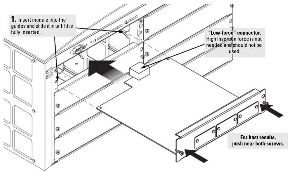
Install switch modules into the slots as shown in the illustration below. For installation details, see the instructions in the manual that comes with the module.
Note
Ensure you install only HP ProCurve Switch gl Modules. Switch xl Modules will fit into your Switch gl slots, but they will not operate.
Avoid any electrostatic discharge problems by handling the modules only by their bulkheads.
The slot cover can be removed, and the module can be installed with either a flat-bladed or Torx T-10 screwdriver. Retain the slot cover for future use.
Module Installation Notes
■ Any of the supported switch modules can be installed in any of the slots.
- The modules can be “hot swapped”, installed after the switch is already powered on, and normally will be immediately operational. But, if you are replacing a module with a different type than what was previously installed in the slot, the switch must be rebooted after the module is installed. See “Hot Swapping the Switch Module” on page 2-21.
The modules employ "low-force" connectors. Using high force to insert the modules is not needed and should not be used.
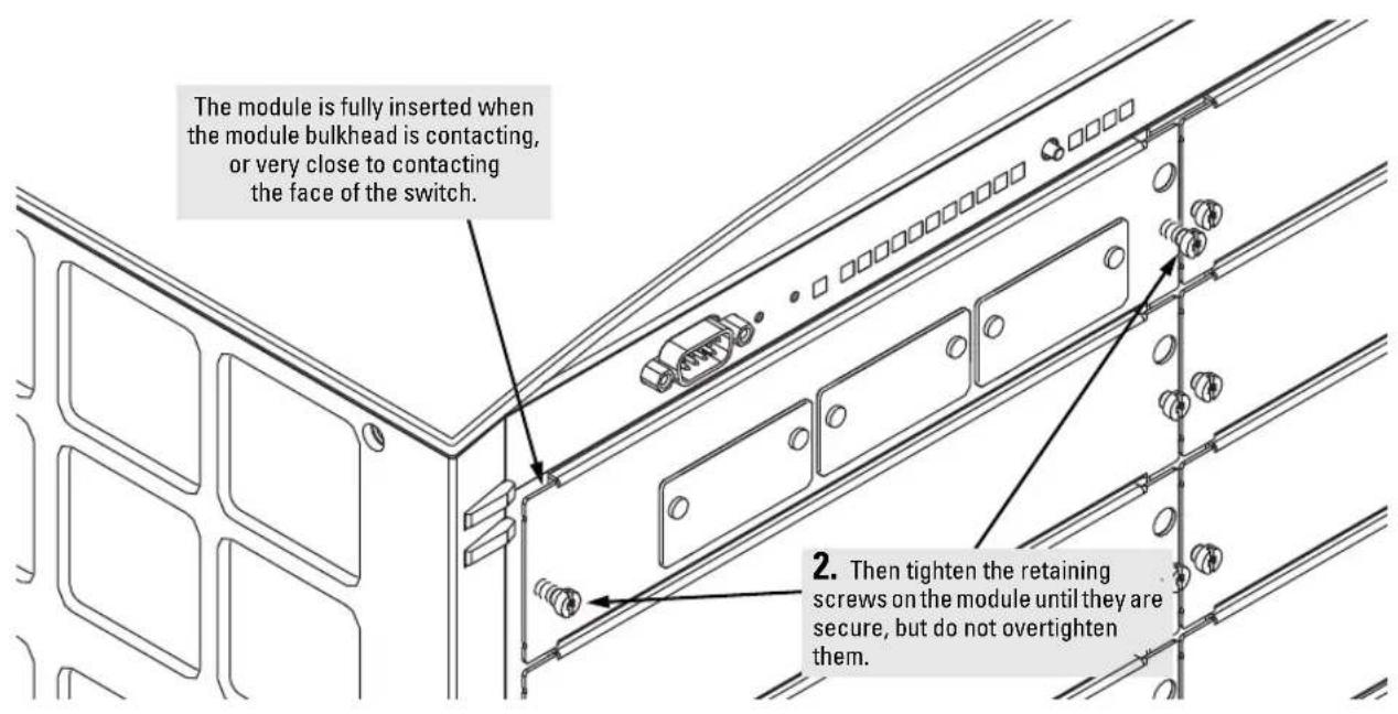
■ Ensure you fully insert the modules. That is, press the module into the slot until the bulkhead on the module is contacting or is very close to contacting the front face of the switch chassis.
■ Once the module is fully inserted, ensure you screw in the two retaining screws to secure the module in place.
If you do not use one or more of the slots, ensure the slot cover plate is still attached over the slot for safe operation and proper switch cooling. For safety, you should not have more than one slot uncovered at a time.
Installing the Series 4100gl Switches Installation Procedures
3. (Optional) Install Second Power Supply
A second, load-sharing redundant power supply (HP ProCurve Switch gl/xl RPS, HP J4839A) can be installed in the back of the switch. To provide true redundancy, this second power supply should be connected to a different AC power source from the other supply. Then, if one AC power source fails, the switch will continue to run. Each supply provides enough power to operate a fully loaded switch, so even if one fails, the switch will continue to operate normally.
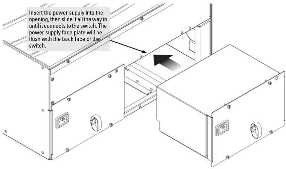
Install the second power supply into power slot number 2 as shown in the illustration on the next page.
The slot cover can be removed with either a flat-bladed or Torx T-10 screw-driver. Retain the slot cover for future use.
Caution
The switch power supplies are hot swappable; they can be installed while the switch is receiving power from the supply in the other slot. But, as indicated by the caution statement on the power supply, the supply must not be connected to AC power before being installed.
Caution: • Refer to the installation guide for proper power cord selection. • Disconnect AC power from this power supply BEFORE installing or removing the supply. Otherwise, damage to the equipment may result.
For safety and proper switch cooling, if either of the power supply slots are not being used, make sure to attach the cover plate over the slot. Please see the Installation Precautions on page 2-3 for more information.
For installation details, see the instructions in the manual that comes with the power supply.
Installing the Series 4100gl Switches
Installation Procedures
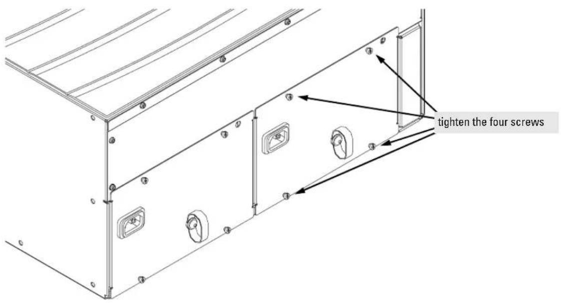
Once the power supply is installed, make sure you tighten the four retaining screws that hold it in place. The screws can be tightened with either a flat-bladed or Torx T-10 screwdriver. Be careful not to overtighten the screws.
4. Verify the Switch Passes Self Test
After you have installed any modules and the optional second power supply, but before mounting the switch in its network location, you should first verify that it is working properly by plugging it into a power source and verifying that it passes its self test.
If you have installed a second power supply, repeat these procedures with the second power supply to verify that it works correctly also.
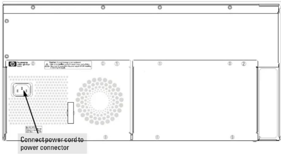
- Connect the power cord supplied with the switch to the power connector on the back of the switch, and then into a properly grounded electrical outlet.
Note
The Series 4100gl Switches do not have a power switch. They are powered on when the power cord is connected to the switch and to a power source.
If your installation requires a different power cord than the one supplied with the switch, please see the Installation Precautions on page 2-3.
- Check the LEDs on the switch and on each of the switch modules. The LED behavior is described on the next page.
If the LED display is different than what is described, especially if the Fault LED stays on for more than approximately 120 seconds or it starts flashing, the self test has not completed correctly. Refer to chapter 4, "Troubleshooting" for diagnostic help.
Installing the Series 4100gl Switches Installation Procedures
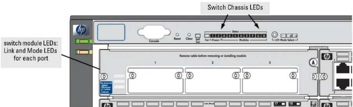
When the switch is powered on, it performs its diagnostic self test. The entire download, initialization, and self test process can take up to 2 1/2 minutes for a fully loaded chassis, depending on the number and type of modules installed in the switch.
LED Behavior:
During the self test:
■ Initially, Power and Fault, and all the switch chassis LEDs are on. Then, after approximately 30 seconds, the Fault LED goes off.
■ After another approximately 5 seconds, the chassis LEDs go off except Power, Self Test, Fan Status, and Power Status, and Module Status. At the same time, all the module LEDs go on as the modules receive power and are downloaded with code.
■ After another approximately 20 seconds, when the download of code to the modules is completed, the module LEDs go off. You may see each port Link LED flash briefly, in sequence, as the ports are tested.
■ For the duration of the self test, the Self Test LED stays on.
When the self test completes successfully:
■ The Power LED stays on, and the Status LEDs on the switch chassis stay on for the devices installed: one for each switch module installed, one for each power supply installed, and one for all the fans.
■ The Fault and Self Test LEDs are off.
■ The port LEDs on the switch modules go into their normal operational mode:
- If the ports are connected to active network devices, the Link LEDs stay on and the Mode LEDs behave according to the mode selected. In the default mode (Activity), the Mode LEDs should flicker showing network activity on the port.
- For the ports that are not connected to active network devices, the LEDs will stay off.
5. Mount the Switch
After the modules and optional power supply are installed and you have verified that the switch passes self test, you are ready to mount the switch in a stable location. The Series 4100gl Switches can be mounted in these ways:
■ in a rack or cabinet
■ on a horizontal surface
■ on a wall
Rack or Cabinet Mounting
The Series 4100gl Switches are designed to be mounted in any EIA-standard 19-inch telco rack or in an equipment cabinet such as a server cabinet. If you are installing the switch in an equipment cabinet, please see the “Equipment Cabinet Note” on page 2-16.
Caution
For safe operation, please read the mounting precautions on page 2-3 before mounting the switch.
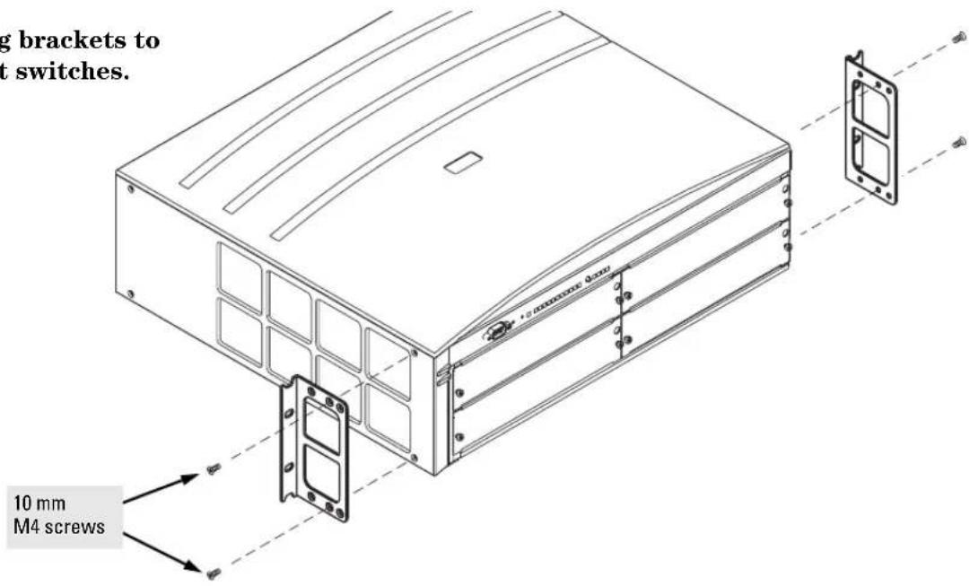
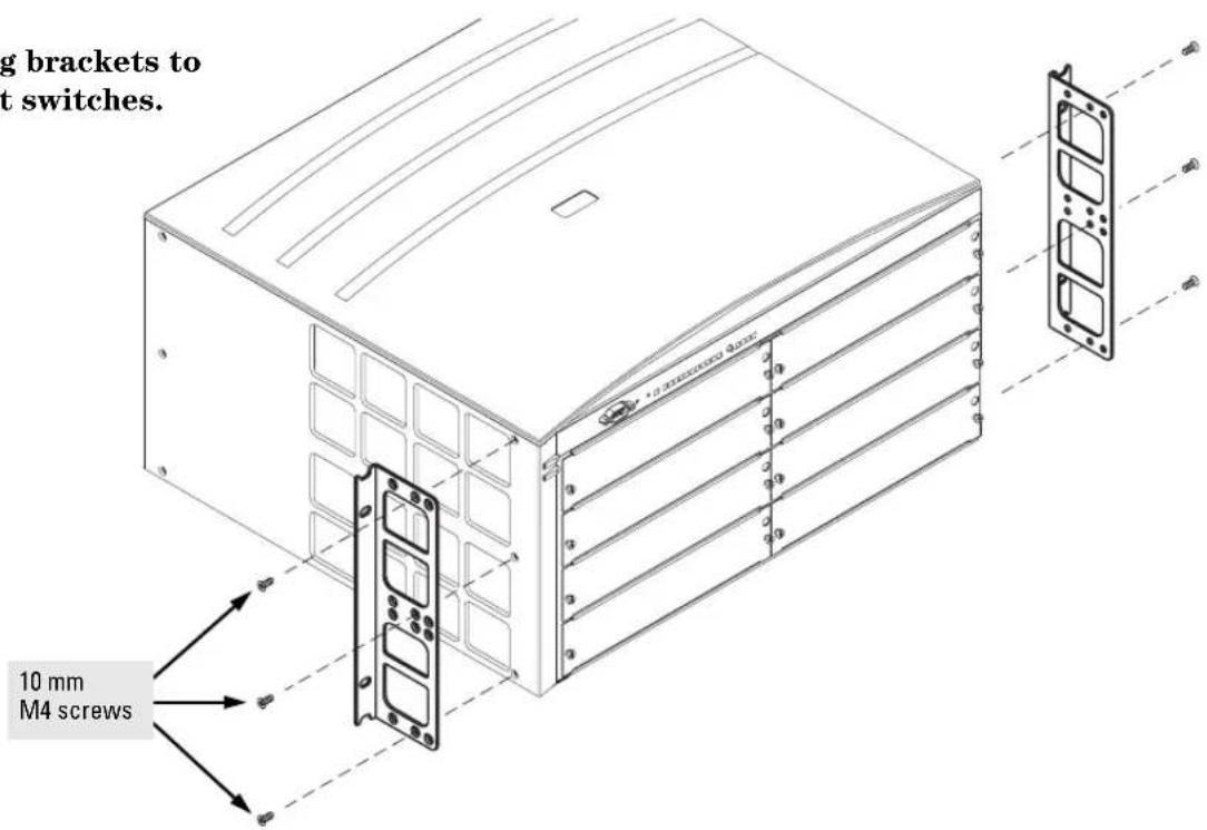
- Use a #1 Phillips (cross-head) screwdriver and attach the mounting brackets to the switch with the included 10-mm M4 screws.
For the 4-slot Switch 4104gl and Switch 4148gl, each bracket is attached with two screws, and for the 8-slot Switch 4108gl and Switch 4108gl Bundle, each bracket is attached with three screws as shown in the illustrations on the next page.
Installing the Series 4100gl Switches Installation Procedures
Attaching brackets to the 4-slot switches.
Attaching brackets to the 8-slot switches.
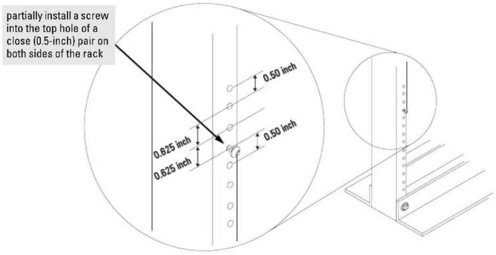
- Partially install a screw (5/8-inch number 12-24) into the top hole of a pair of holes that are 0.5 inches apart in each rack/cabinet upright as shown in the illustration below. Ensure the screws are at the same level in each upright.
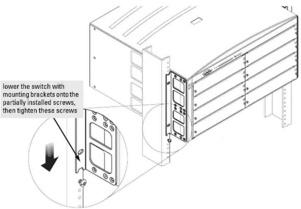
- Place the switch in the rack and lower it so the notches in the bottom of the bracket slide onto the screws, then tighten these screws.
Installing the Series 4100gl Switches Installation Procedures
- Install the other number 12-24 screw into the upper hole in each bracket. Tighten these screws.
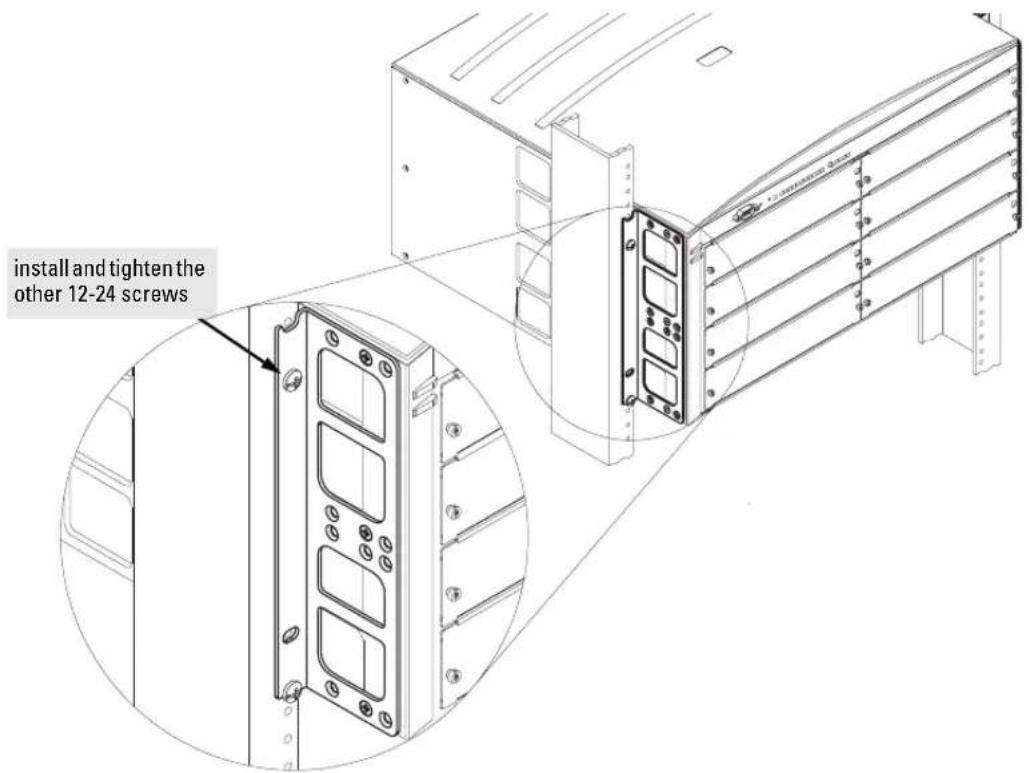
Equipment Cabinet Note
If you are installing the switch in an equipment cabinet, in place of the 12-24 screws supplied with the switch, use the clips and screws that came with the cabinet. Plan which four holes you will be using in the cabinet and install all four clips and partially install the two bottom screws, as described in step 2 on the previous page, before proceeding to step 3.
Horizontal Surface Mounting
Place the switch on a table or other horizontal surface. Use a sturdy surface in an uncluttered area. You may want to secure the networking cables and switch power cord to the table legs or other part of the surface structure to help prevent people from tripping over the cords.
Note
Ensure the air flow is not restricted around the sides and back of the switch.
Wall Mounting
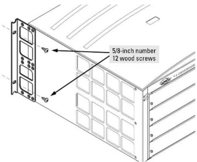
The mounting brackets supplied with the switch allow you to mount it on a wall. The illustrations below show mounting a Switch 4108gl. The Switch 4104gl and 4148gl would be mounted in a similar way.
Caution
For safe operation, do not install the switch with the vents or fans facing downward. The only recommended and supported wall mounting orientation is with the unit upright and the modules facing out, as shown in the illustrations below.
Additionally, the switch should be mounted only to a wall or wood surface that is at least 1/2-inch plywood or its equivalent.
- Use a #1 Phillips (cross-head) screwdriver and attach the mounting brackets to the switch with the included 10-mm M4 screws.
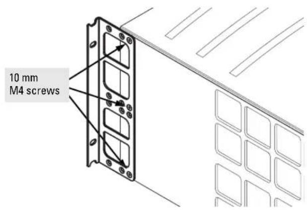
- Attach the switch to the wall or wood surface with four 5/8-inch number 12 wood screws or larger (not included).
6. Connect the Switch to a Power Source
- Plug the included power cord into the switch's power connector and into a nearby properly grounded AC power source.
If you have installed a redundant power supply module into the switch, it should be connected to a separate AC power source. Then, if there is a power outage from one of the AC sources, the switch will continue to operate by power coming from the other source.
See the HP ProCurve Switch gl/xl RPS Installation Guide for additional information.
- Re-check the LEDs during self test. See "LED Behavior" on page 2-12.
7. Connect the Network Devices
The type of network connections you will need to use depends on the types of switch modules you have installed in your Series 4100gl Switch. See the documentation accompanying the modules for cabling configurations and procedures for those modules.
In general for all the modules, when a network cable from an active network device is connected to the switch, the Link LED for the switch port should go on. If the Link LED does not go on, use the table below to help solve the problem, and see the module documentation for troubleshooting procedures.
Condition Diagnostic Tip
Port LED is still off when a cable is connected
Try the following procedures:
- For the indicated port, verify that both ends of the cabling, at the switch and the connected device, are securely connected.
- Verify the connected device and switch are both powered on and operating correctly.
-
Verify you have used the correct cable type for the connection:
-
for all twisted-pair connections, the RJ-45 connectors on the Series 4100gl Switches allow you to use either straight-through cable or crossover cable when the port is in the "Auto" configuration.
- for fiber-optic connections, verify that the transmit port on the switch is connected to the receive port on the connected device, and the switch receive port is connected to the transmit port on the connected device.
See appendix B, "Cables and Connectors" for information on cables.
- Verify the port has not been disabled through a switch configuration change.
- Verify the connection parameters in the configurations of the switch port and the connected device match. Mismatched configurations are a frequent cause of connection problems.
You can use the console interface, or, if you have configured an IP address on the switch, use the web browser interface, or HP ProCurve Manager for Hubs & Switches network management software to determine the state and configuration of the port and re-enable the port if necessary.
- If the other procedures don't resolve the problem, try using a different port or a different cable.
8. (Optional) Connect a Console to the Switch
The Series 4100gl Switches have a full-featured, easy to use console interface for performing the following tasks:
Monitor switch and port status and observe network activity counters
- Modify the switch's configuration
Read the event log and access diagnostic tools to help in troubleshooting
- Download new software to the switch
Add passwords and other security features to control access to the switch from the console, web browser interface, and network management stations
The console can be accessed through these methods:
Out-of-band: Connect a PC or VT-100 terminal, to be used as a console, directly to the switch using the serial cable that comes with the Series 4100gl Switches. If the PC or terminal has a 25-pin serial connector, you can use a readily available 9-pin to 25-pin serial cable, or attach a 9-to-25 pin straight-through adapter to the PC end of the cable.
In-Band: Access the console using telnet from a PC or UNIX station on the network, and a VT-100 terminal emulator. This method requires that you first configure the switch with an IP address and subnet mask by using either out-of-band console access or through DHCP/Bootp.
The Series 410gl Switches can simultaneously support one out-of-band console session through the Console Port and one in-band telnet session.
Terminal Configuration
To connect a console to the switch, configure the PC terminal emulator as a VT-100 or DEC VT-100 (ANSI) terminal, or use a VT-100 terminal and configure it to operate with these settings:
any baud rate from 2400 to 115200 (the switch automatically senses the speed)
8 data bits, 1 stop bit, no parity, and flow control set to None
For Windows Terminal program, also disable (unchecked) the "Use Function, Arrow, and Ctrl Keys for Windows" option
For the Hilgrave HyperTerminal program, select the "Terminal keys" option for the "Function, arrow, and ctrl keys act as" parameter
If you want to operate the console using a different configuration, make sure you change the settings on both the terminal and on the switch. Change the switch settings first, then change the terminal settings, and reestablish the console session.
Direct Console Access
To connect a console to the switch, follow these steps:
- Connect the PC or terminal to the switch's Console Port using the console cable included with the switch. (If your PC or terminal has a 25-pin serial connector, first attach a 9-pin to 25-pin straight-through adapter to the PC end of the console cable.)
- Turn on the terminal or PC's power and, if using a PC, start the PC terminal program.
- Press two or three times and you will see the copyright page and the message "Press any key
flowchart
graph TD
    A["console port"] --> B["Switch"]
    B --> C["PC running a terminal emulator program, or a VT-100 terminal"]
    C --> D["Computer"]
to continue". Press a key, and you will then see the switch console CLI prompt.
Telnet Console Access
To access the switch through a telnet session, follow these steps:
- Ensure the switch is configured with an IP address and that the switch is reachable from the telnet workstation (for example by using a Ping command to the switch's IP address)
- Start the telnet program and connect to the switch's IP address.
- You will see the copyright page and the message "Press any key to continue". Press a key, and you will then see the switch console CLI prompt.
If you want to continue with console management of the switch at this time through either a direct connection or a telnet session, see chapter 3, “Getting Started With Switch Configuration” for some basic configuration steps. For more detailed information, refer to the Management and Configuration Guide that is on the documentation CD-ROM that came with your switch.
Hot Swapping Switch Modules
The switch modules can be “hot swapped”, that is installed or replaced while the switch is powered on. The procedures differ slightly, though between adding new modules to an empty slot or replacing modules with the same type, and exchanging the module with a different type.
Adding or Replacing Modules
If a module has to be replaced with one of the same type, or you are expanding the switch capability by adding a module in a slot where one was not previously installed (since the last switch reboot), the replaced or new module is immediately operational; there is no interruption to the switch operation.
Changing the Module Type
If you exchange a module with a different type of module though, for example a 100/1000-T gl Module is installed in place of a 10/100-TX gl Module that was in the slot, the switch must be rebooted after the new module is installed so the switch processor can properly initialize and configure the new module type.
You can reboot the switch by any of the following methods:
Pressing the Reset button on the front of the switch.
Unplugging and plugging in the power cord (power cycle). If two power supplies are installed, both power cords would have to be unplugged.
issuing the reboot system command from the switch console CLI, or selecting the Reset or Reboot option from the switch console menu, the web browser interface, or HP ProCurve Manager for Hubs & Switches
Until the switch is rebooted, the module will not operate and the Module Status LED for the affected slot will continue to flash.
Example Network Topologies
This section shows you a few example network topologies in which the Series 4100gl Switches can be implemented. For more topology information, see the HP network products World Wide Web site, http://www.hp.com/go/hpprocurve.
Basic Connectivity
flowchart
graph TD
    A["Server connected by a Gigabit link"] --> B["Switch 4108gl"]
    C["twisted-pair "straight-through" or "crossover" cables"] --> B
    D["PCs and peripherals"] --> B
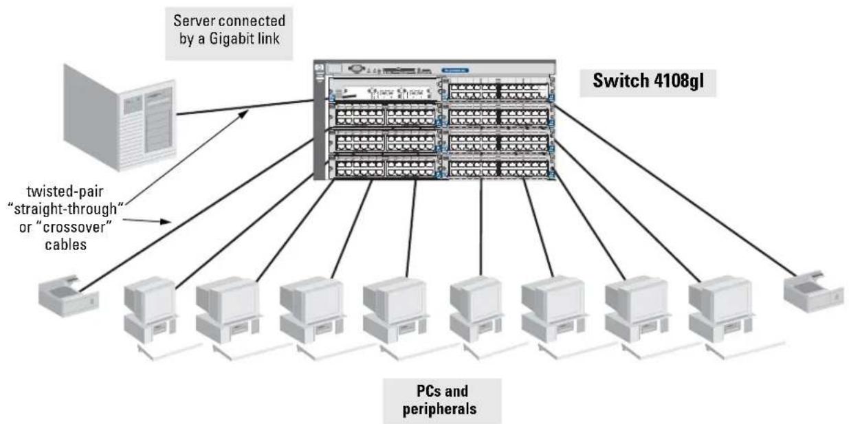
The Series 4100gl Switches can provide basic network connectivity to a high number of users. End nodes, printers and other peripherals, and servers can be easily connected, as shown in the above illustration.
Notice the end node devices are connected to the switch by either straight-through or crossover twisted-pair cables. Either cable type can be used because of the "HP Auto-MDIX" feature on the 10/100-TX gl Modules and the standard "Auto MDI/MDI-X" feature on the 100/1000-T gl Transceiver to which the server is connected. The six twisted-pair ports on the 100/1000-T gl Module also support the "Auto MDI/MDI-X" feature.
Use as an Edge Switch
flowchart
graph TD
    A["HP ProCurve Routing Switch 9308"] --> B["Switch 4108gl"]
    A --> C["Switch 4108gl"]
    B --> D["Trunked redundant Gigabit fiber-optic cables"]
    C --> E["Trunked redundant Gigabit fiber-optic cables"]
    D --> F["Computer"]
    D --> G["Computer"]
    D --> H["Computer"]
    D --> I["Computer"]
    D --> J["Computer"]
    D --> K["Computer"]
    D --> L["Computer"]
    D --> M["Computer"]
    D --> N["Computer"]
    D --> O["Computer"]
    D --> P["Computer"]
    D --> Q["Computer"]
    D --> R["Computer"]
    D --> S["Computer"]
    D --> T["Computer"]
    D --> U["Computer"]
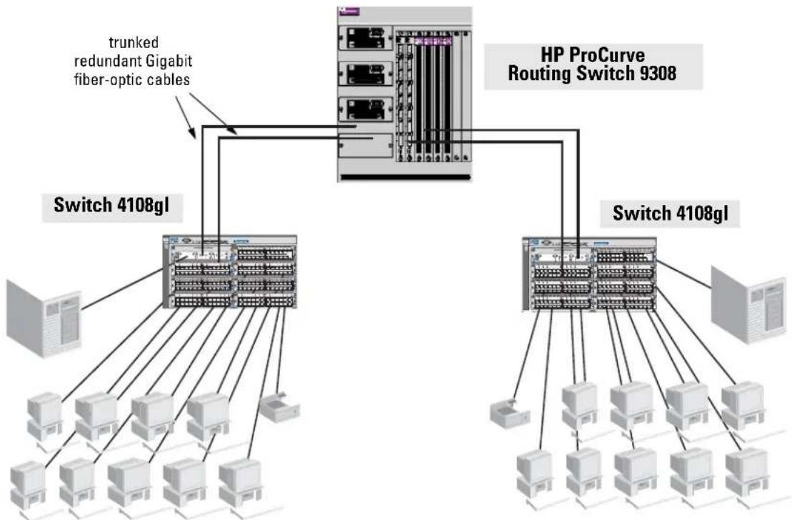
When your network expands and the users need to access resources beyond the edge of the local network, the Series 4100gl Switches are excellent platforms for that expansion. With the flexibility of 4 or 8 slots, the high port count 10/100-TX gl Module for local connections, and the availability of Gigabit speeds through either the Gigabit Transceiver gl Module or the 100/1000-T gl Module, the Series 4100gl Switches can provide that access beyond the edge for a high number of network users.
In the above illustration, two Switch 4108gls are connected to an HP ProCurve Routing Switch 9308, which can serve as a campus backbone or core switch.
The 1000 Mbps fiber-optic connections between the two Switch 4108gls and the Routing Switch 9308 is by way of Gigabit-LX Transceivers installed in Gigabit Transceiver gl Modules in the Switch 4108gls and Gigabit-LX ports on the Routing Switch 9308. With the Gigabit-LX connections, the distance between the Switch 4108gls and the Routing Switch 9308 can be up to ten kilometers.
The connections are trunked, through a configuration change on the Switch 4108gl, to provide redundancy and load sharing for higher bandwidth.
Stacking the Switches
The Series 4100gl Switches can be connected together, through standard network connections, and managed through a single IP address. Up to 16 switches can be connected together in such a “virtual stack”.
You identify one of the switches as the “Commander” and give that switch an IP address. Up to 15 other switches in the network can then easily be configured as Members of the stack and managed through the Commander's IP address. The management includes Telnet access and web browser interface access to the Commander and to each Member switch through the Commander.
For more information on stacking your Series 4100gl Switches, please see the Management and Configuration Guide that is on the documentation CD-ROM that came with your switch.
Getting Started With Switch Configuration
This chapter is a guide for using the console Switch Setup screen to quickly assign an IP (Internet Protocol) address and subnet mask to the switch, set a Manager password, and, optionally, configure other basic features.
For more information on using the switch console and the other switch management interfaces: the web browser interface and the SNMP management tool, HP ProCurve Manager for Hubs & Switches, please see the Management and Configuration Guide on the documentation CD-ROM that came with your switch.
Recommended Minimal Configuration
In the factory default configuration, the switch has no IP (Internet Protocol) address and subnet mask, and no passwords. In this state, it can be managed only through a direct console connection. To manage the switch through in-band (networked) access, you should configure the switch with an IP address and subnet mask compatible with your network. Also, you should configure a Manager password to control access privileges from the console and web browser interface. Other parameters in the Switch Setup screen can be left at their default settings or you can configure them with values you enter.
Many other features can be configured through the switch's console interface, to optimize the switch's performance, to enhance your control of the network traffic, and to improve network security. Once an IP address has been configured on the switch, these features can be accessed more conveniently through a remote Telnet session, through the switch's web browser interface, and from an SNMP network management station running a network management program, such as HP ProCurve Manager for Hubs & Switches. For a listing of switch features available with and without an IP address, refer to “How IP Addressing Affects Switch Operation” in the Management and Configuration Guide that is on the documentation CD-ROM that came with your switch.
For more information on IP addressing, refer to “IP Configuration” in the Management and Configuration Guide.
Note
By default, the switch is configured to acquire an IP address configuration from a DHCP or Bootp server. To use DHCP/Bootp instead of the manual method described in this chapter, see “DHCP/Bootp Operation” in the Management and Configuration Guide that is on the documentation CD-ROM that came with your switch.
Using the Switch Setup Screen
The quickest and easiest way to minimally configure the switch for management and password protection in your network is to use a direct console connection to the switch, start a console session, and access the Switch Setup screen.
- Using the method described in the preceding section, connect a terminal device to the switch and display the switch console command (CLI) prompt (the default display).
The CLI prompt appears displaying the switch model number:
HP Procurve Switch 4104GL#
- At the prompt, enter the setup command to display the Switch Setup screen. The following illustration shows the Setup screen with the default settings.
![HP ProCurve Switch 4104GL 12-Mar-2002 16:40:46 ==================== CONSOLE - MANAGER MODE ==================== Switch Setup System Name : HP ProCurve Switch 4104GL System Contact : Manager Password : Confirm Password : Logon Default : CLI Time Zone [0] : 0 Community Name : public Spanning Tree Enabled [No] : No Default Gateway : Time Sync Method [None] : None IP Config [DHCP/Bootp] : DHCP/Bootp IP Address : Subnet Mask : Actions-> Cancel Edit Save Help Enter System Name - up to 25 characters. Use arrow keys to change field selection, to toggle field choices, and to go to Actions.](/content/2026/06/1201911/images/19e677631b22998689b6086688ce4cdf3ed4677387bc3667b9902caaaf7b2f21.jpg)
-
Use the key to select the Manager Password field and enter a manager password of up to 16 characters.
-
to the IP Config (DHCP/Bootp) field and use the Space bar to select the Manual option.
- to the IP Address field and enter the IP address that is compatible with your network.
- to the Subnet Mask field and enter the subnet mask used for your network.
- Press ( \overline{\overline{\overline{\overline{\overline{\overline{\overline{\overline{\overline{\overline{\overline{\overline{\overline{\overline{\overline{\overline{\overline{\overline{\overline{\overline{\overline{\overline{\overline{\overline{\overline{\overline{\overline{\overline{\overline{\overline{\overline{\overline{\overline{\overline{\varepsilon}}}}}}}}}}}}}}}}}}}}}}}}}}}}}}}}}}}}}}}}}}}}}}}}}}}}}}}}}}}}}}}}}}}}}}}}}}}}}}}}}}}}}}}}}}}}}}}}}}}}}}}}}}}}}}}}}}}}}}}}}}}}}}}}}}}}}}}}}}}}}}}}}}}}}}}}}}}}}}}}}}}}}}}}}}}}}}}}}}}}}}}}}}}}}}}}}}}}}}}}})
The following is information on the fields in the Setup screen. For more information on these fields, see the Management and Configuration Guide that is on the documentation CD-ROM that came with your switch:
Parameter Default
| System Name | blank | Optional; up to 25 characters, including spaces |
| System Contact | blank | Optional; up to 48 characters, including spaces |
| Manager Password | blank | Recommended; up to 16 characters (no blank spaces) |
| Logon Default | CLI | The default setting selects the command line interface for console access. The alternative is the menu interface. |
| Time Zone | 0 (none) | Optional; 1440 to -1440. The number of minutes your location is to the West (-) or East (+) of GMT. |
| Community Name | public | Default setting recommended. |
| Spanning Tree Enabled | No | Default setting recommended unless STP is already running on your network or the switch will be used in complex network topologies. |
| Default Gateway | blank | Recommended; Enter the IP address of the next-hop gateway node if network traffic needs to be able to reach off-subnet destinations. |
| Time Sync Method | None | Optional; The protocol the switch uses to acquire a time signal. The options are SNTP and TimeP. |
| IP Config | DHCP/Bootp | Set to Manual unless a DHCP/Bootp server is used on your network to configure IP addressing. |
| IP Address | xxx.xxx.xxx.xxx | Recommended; If you set IP Config to Manual, then enter an IP address compatible with your network. |
| Note: The IP address and subnet mask assigned for the switch must be compatible with the IP addressing used in your network. For more information on IP addressing, see the Management and Configuration Guide that is on the documentation CD-ROM that came with your switch. | ||
| Subnet Mask | xxx.xxx.xxx.xxx | Recommended; If you entered an IP address, then enter a subnet mask compatible with your network. |
The switch is now configured with a Manager password, IP address, and subnet mask. As a result, the switch can be accessed through your network using Telnet, the web browser interface, or an SNMP-based network management tool such as HP ProCurve Manager for Hubs & Switches.
To Recover from a Lost Manager Password: If you cannot start a console session at the manager level because of a lost Manager password, you can clear all passwords and user names by getting physical access to the switch and pressing and holding the Clear button for a full second.
Where to Go From Here
The above procedure configures your switch with a Manager password, IP address, and subnet mask. With the proper network connections, you can now manage the switch from a PC equipped with Telnet and/or a web browser or from an SNMP network management station.
Some basic information on managing your switch is included in the next section. For more information on the console, web browser, and SNMP management interfaces and all the features that can be configured on the Series 4100gl Switches, please see the Management and Configuration Guide that is on the documentation CD-ROM that came with your switch.
Using the IP Address for Remote Switch Management
With your Series 4100gl Switches, you can use the switch's IP address to manage the switch from any PC that is on the same subnet as the switch. You can use either a Telnet session or a standard web browser to manage the switch.
Starting a Telnet Session
To access the switch through a Telnet session, follow these steps:
- Ensure the switch is configured with an IP address and the switch is reachable from the PC that is running the Telnet session (for example, by using a Ping command to the switch's IP address).
- Start the Telnet program on a PC that is on the same subnet as the switch and connect to the switch's IP address.
- You will see the copyright page and the message "Press any key to continue". Press a key, and you will then see the switch console command (CLI) prompt, for example:
HP Procurve Switch 4108GL#
Enter help or ? to see a list of commands that can be executed at the prompt. Entering any command followed by help provides more detailed context help information about the command.
Starting a Web Browser Session
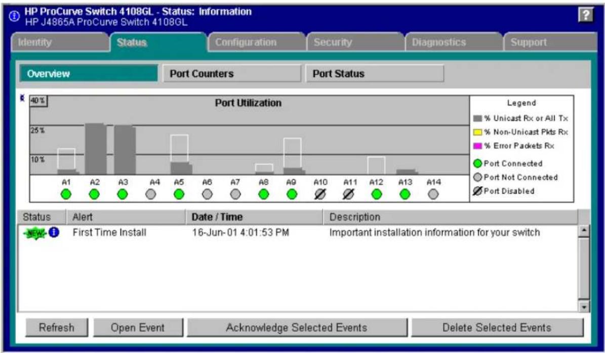
Your Series 4100gl Switch can be managed through a graphical interface that you can access from any PC or workstation on the network by running your web browser and typing in the switch's IP address as the URL. No additional software installation is required to make this interface available; it is included in the switch's onboard software.
A typical web browser interface screen is shown in the next illustration.
Getting Started With Switch Configuration
Using the IP Address for Remote Switch Management
bar
HP ProCurve Switch 4108GL - Status: Information HP J4865A ProCurve Switch 4108GL Identity StatusCaliforniaConfigurationSecurityDiagnosticsSupport Overview Port Counters Port Status Port Utilization Legend % Unicast Rx or All Tx % Non-Unicast Pkts Rx % Error Packets Rx ● Port Connected ○ Port Not Connected ∅ Port Disabled A1 A2 A3 A4 A5 A6 A7 A8 A9 A10 A11 A12 A13 A14 Status Alert Data / Time Description - New - First Time Install 16-Jun-01 4:01:53 PM Important installation information for your switch Refresh Open Event Acknowledge Selected Events Delete Selected EventsFor more information on using the web browser interface, please see the Management and Configuration Guide that is on the documentation CD-ROM that came with your switch.
An extensive help system is also available for the web browser interface. To access the help system though, the subnet on which the switch is installed must have access to the internet, or HP ProCurve Manager for Hubs & Switches needs to be installed on a network management station that is on the subnet.
Troubleshooting
This chapter describes how to troubleshoot your Series 4100gl Switches. This document describes troubleshooting mostly from a hardware perspective. You can perform more in-depth troubleshooting using the software tools available with the switch, including the full-featured console interface, the built-in web browser interface, and HP ProCurve Manager for Hubs & Switches, the SNMP-based network management tool. For more information, see the chapter on “Troubleshooting” in the Management and Configuration-Guide that is on the documentation CD-ROM included with your switch.
This chapter describes the following:
basic troubleshooting tips (page 4-1)
diagnosing with the LEDs (page 4-4)
Proactive Networking tools (page 4-9)
hardware diagnostic tests (page 4-10)
restoring the factory default configuration (page 4-12)
downloading new code (page 4-13)
HP Customer Support Services (page 4-13)
Basic Troubleshooting Tips
Most problems are caused by the following situations. Check for these items first when starting your troubleshooting:
Faulty or loose cables. Look for loose or obviously faulty connections. If they appear to be OK, ensure the connections are snug. If that does not correct the problem, try a different cable.
Non-standard cables. Non-standard and miswired cables may cause network collisions and other network problems, and can seriously impair network performance. Use a new correctly-wired cable or compare your cable to the cable in appendix B, "Cables and Connectors" for pinouts and correct cable wiring. A category 5 cable tester is a recommended tool for every 100Base-TX and 1000Base-T network installation.
Troubleshooting Basic Troubleshooting Tips
- Improper Network Topologies. It is important to make sure you have a valid network topology. Common topology faults include excessive cable length and excessive repeater delays between end nodes. If you have network problems after recent changes to the network, change back to the previous topology. If you no longer experience the problems, the new topology is probably at fault. Some basic sample topologies are shown at the end of chapter 2 in this manual.
In addition, you should make sure that your network topology contains no data path loops. Between any two end nodes, there should be only one active cabling path at any time. Data path loops will cause broadcast storms that will severely impact your network performance.
With your Series 4100gl Switches, if you wish to build redundant paths between important nodes in your network to provide some fault tolerance, you should enable Spanning Tree Protocol support on the switch. This ensures that only one of the redundant paths is active at any time, thus avoiding data path loops. Spanning Tree can be enabled through the switch console, the web browser interface, or HP ProCurve Manager for Hubs and Switches.
The Series 4100gl Switches also support Trunking, which allows multiple network cables to be used for a single network connection without causing a data path loop. See the Management and Configuration Guide that is on the documentation CD-ROM that came with your switch for more information on Spanning Tree and on Trunking.
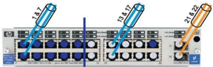
- Trunking for the J4908A is accomplished differently than normal, therefore you must follow these guidelines. Looking at the J4908A physical port layout, it looks like this:
| 1 2 | 3 4 | 5 6 | 13 14 | 15 | 16 21 | |||||
| 7 | 8 | 9 | 10 | 11 | 12 | 17 | 18 | 19 | 20 | 22 |
The trunking grouping is as follows:
Group1: 1-5, 7-11, 16
Group2: 6, 12-15, 17-22
Ports 21 and 22, which are the two Fiber links, are expected to be trunked together. The following graphic depicts the proper trunking.
■ Connecting to devices that have a fixed full-duplex configuration.
The RJ-45 ports on the Series 4100gl Switches are all configured as "Auto". That is, when connecting to attached devices, the switch will operate in one of two ways to determine the link speed and the communication mode (half duplex or full duplex):
- if the connected device is also configured to Auto, the switch will automatically negotiate both link speed and communication mode
- if the connected device has a fixed configuration, for example 100 Mbps, at half or full duplex, the switch will automatically sense the link speed, but will default to a communication of half duplex
Because the Series 4100gl Switches behave in this way (in compliance with the IEEE 802.3 standard), if a device connected to the switch has a fixed configuration at full duplex, the device will not connect correctly to the switch. The result will be high error rates and very inefficient communications between the switch and the device.
Ensure that all devices connected to the Series 4100gl Switches are configured to auto negotiate, or are configured to connect at half duplex (all hubs are configured this way, for example).
If necessary though, you can modify the configuration of the ports on the Series 4100gl Switches to match the configuration of the connected device. Use the switch console, the web browser interface, or HP ProCurve Manager for Hubs & Switches to modify the port configuration.
- Check the port configuration. A port on your Series 4100gl Switch may not be operating as you expect because it has been put into a “blocking” state by Spanning Tree, GVRP (automatic VLANs), or LACP (automatic trunking). (Note that the normal operation of the Spanning Tree, GVRP, and LACP features may put the port in a blocking state.) Or, the port just may have been configured as disabled through software.
Use the switch console to determine the port's configuration and verify there is not an improper or undesired configuration of any of the switch features that may be affecting the port. See the Management and Configuration Guide that is on the documentation CD-ROM that came with your switch for more information.
For more information on possible network problems and their solutions, refer to the technical note “Troubleshooting LAN Performance and Intermittent Connectivity Problems”, which can be found on the HP ProCurve web site, http://www.hp.com/go/hpprocurve, in the Information Library section.
Diagnosing with the LEDs
Table 4-1 shows LED patterns on the switch and the switch modules that indicate problem conditions.
- Check in the table for the LED pattern that you see on your switch
- Refer to the corresponding diagnostic tip on the next few pages.
Table 4-1. LED Error Indicators
| LED Pattern Indicating Problems | Diagnostic Tips | ||||||
| Power | Fault | Self Test | Module Status (one LED per module) | Power Status (one LED per power supply) | Fan Status | Port Link | |
| Off with power cord plugged in | * * * * | * * | 1 | ||||
| On Prolonged On | Prolonged On | * * * * | * | 2 | |||
| On Flashing | Flashing^ | Off * * | * | 3 | |||
| On Flashing | Flashing^ | Flashing^ | * * Never On | 4 | |||
| On Flashing | Flashing^ | Flashing^ | * * On briefly, | then Off | 5 | ||
| On Off Off Flashing | * * * | 6 | |||||
| On Flashing | Flashing^ | Flashing^ | * * Flashing | 7 | |||
| On Flashing | Off | * | Flashing^ | * * | 8 | ||
| On Flashing | Off | * | * | Flashing^ | * | 9 | |
| On | Off | Off | * | * | Fast Flashing^ | 10 | |
| On | Off | Off | * | * | Off with cable connected | 11 | |
| * This LED is not important for the diagnosis. ^ The flashing behavior is an on/off cycle once every 1.6 seconds, approximately. ^ The fast flashing behavior is an on/off cycle once every 0.8 seconds, approximately | |||||||
Diagnostic Tips:
| Tip Number | Problem Solution | |
| 1 | The power supplies installed in the switch are not plugged into active AC power sources, or the power supply may have failed. | 1. Verify the power cord is plugged into an active power source and to the switch.Ensure these connections are snug.2. Try power cycling the switch by unplugging and plugging the power cord back in.3. If the Power LED is still not on, verify the AC power source works by plugging another device into the outlet. Or try plugging the switch into a different outlet or try a different power cord.If the power source and power cord are OK and this condition persists, the switch power supply may have failed. Call your HP-authorized LAN dealer, or use the electronic support services from HP to get assistance. See the Customer Support/Warranty card for more information. |
| 2 | A switch hardware failure has occurred. All the LEDs will stay on indefinitely. | Try power cycling the switch. If the fault indication reoccurs, the switch may have failed. Call your HP-authorized LAN dealer, or use the electronic support services from HP to get assistance. See the Customer Support/Warranty card for more information. |
| 3 | The switch has experienced a backplane failure during self test. | The failure may be just in the communications with a single module slot, or it might be more significant. Start a console session with the switch, and at the CLI prompt issue the commandshow logging.In the event log that is displayed, there will be messages that describe the extent of the problem. If the problem is with individual slots, the remainder of the switch slots will be fully operational and can be used until you get a chance to replace the switch.If necessary to resolve the problem, contact your HP-authorized LAN dealer, or use the electronic support services from HP to get assistance. See the Customer Support/Warranty card for more information. |
| 4 | The module installed in the slot that corresponds to the letter that is flashing is an invalid module. | The fact that the Link and Mode LEDs never are lit on the module indicates that it is a ProCurve Switch xl module and should not be used in your gl switch. Ensure you have installed agl module in the slot. HP ProCurve xl modules will fit in the slot, but they are not compatible with your ProCurve gl switch. Check to ensure the module has a blue “gl module” symbol on it.Remove the module from the switch and replace it with a gl module, or recover the slot with the cover plate. You can remove and replace the module without having to power down the switch. Call your HP-authorized LAN dealer, or use the electronic support services from HP to get information on supported Switch gl modules. The modules that are available as of the printing of this manual are listed onpage 1-10. Ensure you have installed agl module in the slot. HP ProCurve xl modules will fit in the slot, but they are not compatible with your ProCurve gl switch. Check to ensure the module has a blue “gl module” symbol on it.Remove the module from the switch and replace it with a gl module, or recover the slot with the cover plate. You can remove and replace the module without having to power down the switch. Call your HP-authorized LAN dealer, or use the electronic support services from HP to get information on supported Switch gl modules. The modules that are available as of the printing of this manual are listed onpage 1-10. |
Troubleshooting
Diagnosing with the LEDs
| Tip Number | Problem Solution | |
| 5 | The module installed in the slot that corresponds to the letter that is flashing has experienced a self test or initialization fault. | The modules are all tested whenever the switch is powered on, or reset (through the Reset button on the switch, or the Reboot or Reset options in the console or web browser interface), and when they are hot swapped (installed when the switch is powered on).Since the Link and Mode LEDs on the module were lit at least briefly, that indicates that the module did receive power from the switch, but the subsequent download process failed. Either the module is faulty, or it is a new module type that is not yet supported by the operating code on the switch.As Hewlett-Packard introduces new modules for your HP ProCurve Switch gl, you may have to update the switch with new operating code that supports the new module. The documentation that came with the module will indicate which version of the operating code is needed to support the module. The modules that are supported in your Switch gl, as of the printing of this manual, are listed on page 1-10 under "Switch Features". The latest code can be downloaded from the HP ProCurve web site at http://www.hp.com/go/hpprocurve.First verify the switch has a version of code that supports the module that is indicating the fault. If the module is not one of the ones listed on page 1-10, check the module documentation to see what version of switch code is needed. Download the new code and retest the module.If you have the correct code installed in the switch, try removing and reinstalling the module. You can do this without having to power down the switch. When the module is reinstalled, it will be retested automatically.If the fault indication reoccurs, the module may have failed. Remove the module from the switch and replace it with another module, or recover the slot with the cover plate. Call your HP-authorized LAN dealer, or use the electronic support services from HP to get assistance. See the Customer Support/Warranty card for more information. |
| 6 | In the slot corresponding to the letter that is flashing, a module was installed that is a different type than the previously installed module, and the switch has not yet been reset. | When you "hot swap" modules in the switch slots, if you install a different module type than the one that was previously installed in the slot, you must reset the switch so the switch processor can properly initialize and configure the new module type. The flashing LED informs you that this change of module types has occurred. The module will not work properly until the switch is reset.You can reset the switch by any of these methods:pressing the Reset button.power cycling the switch.selecting the reset or reboot option from the console, web browser interface, or HP ProCurve Manager. |
| 7 | The network port for which the Link LED is flashing has experienced a self test or initialization failure. | During the module self test, described in tip number 4 earlier in this table, each network port is also tested. If the port self test fails, the individual port is not usable, but the rest of the ports on the module, which have passed their self test, will continue to operate normally.If the port is a mini-GBIC, verify it is one of the mini-GBICs supported by the mini-GBIC gl Module. Unsupported mini-GBICs will be identified with this fault condition. The supported mini-GBICs are listed in the module Installation Guide. The mini-GBICs are also tested when they are “hot-swapped”--installed or changed while the mini-GBIC xl Module is installed and receiving power from the switch.To verify the port has failed, try removing and reinstalling the module, as described in tip number 4. For the mini-GBICs, you can just remove and reinstall the mini-GBIC without having to remove the module. If the port fault indication reoccurs, and you need to be able to use the port, you will have to replace the module or the mini-GBIC. In the mean time, all the other module ports will operate normally. |
| 8 | A fault condition has been detected on the power supply installed in the slot corresponding to the flashing number. | Try removing and reinstalling the power supply.Caution: Ensure the AC power cord is disconnected from the supply before removing and reinstalling the supply.Reconnect the power supply to the AC power source. If the error indication reoccurs after the supply is reinstalled, the power supply may be faulty. Call your HP-authorized LAN dealer, or use the electronic support services from HP to get assistance. See the Customer Support/Warranty card for more information. |
| 9 | One or more of the switch cooling fans may have failed. | Try disconnecting power from the switch and wait a few moments. Then reconnect the power to the switch and check the LEDs again. If the error indication reoccurs, one or more of the fans has failed. The switch has multiple fans and may continue to operate OK under this condition if the ambient temperature does not exceed normal room temperature, but for best operation, the switch should be replaced. Contact your HP-authorized LAN dealer, or use the electronic support services from HP to get assistance. See the Customer Support/Warranty card for more information. |
| 10 | The network port for which the Link LED is flashing has been disabled because port security has been configured on the switch and a security violation has been detected on the port. | For the Port Security feature, you can configure the switch so that whenever a security violation is detected on a port, the switch will disable the port. When a port is disabled by this feature, the port Link LED will be continuously flashed at the fast rate of 0.8 seconds per cycle. The flashing continues until you clear the security violation through the switch console. In the console, you can view the identity of the connected device that committed the security violation.Once the security violation is cleared, you must re-enable the port through the console.For more information on the Port Security feature, see the Management and Configuration Guide that is on the documentation CD-ROM that came with your switch. |
Troubleshooting
Diagnosing with the LEDs
| Tip Number | Problem Solution | |
| 11 | The network connection is not working properly. | Try the following procedures:For the indicated port, verify that both ends of the cabling, at the switch and the connected device, are securely connected.Verify the connected device and switch are both powered on and operating correctly.Verify you have used the correct cable type for the connection.- for any of the twisted-pair connections, in the default configuration (Auto), either a straight-through or a crossover cable can be used and the switch will automatically adjust its operation. See the "HP Auto-MDIX Feature" description on page B-3 for more information.Note:If the module configuration is changed to one of the fixed configuration options though (for example, 100-Full Duplex), then the port operates as MDI-X only and the correct type of cable must be used. in general, for connecting to an end node (MDI port.), use straight-through cable; for connecting to MDI-X ports on hubs, other switches, and routers, use crossover cable.- for fiber-optic connections, verify the transmit port on the switch is connected to the receive port on the connected device, and the switch receive port is connected to the transmit port on the connected device, and that both devices are transmitting correctly.For a 1000 Mbps connection, verify the network cabling complies with the IEEE 802.3ab standard. The cable should be installed according to the ANSI/TIA/EIA-568-A-5 specifications. Cable testing should comply with the stated limitations for Attenuation, Near-End Crosstalk, Far-End Crosstalk, Equal-Level Far-End Crosstalk (ELFEXT), Multiple Disturber ELFEXT, and Return Loss.The cable verification must include all patch cables from any end devices, including the switch, to any patch panels in the cabling path.Verify the port has not been disabled through a switch configuration change. You can use the console interface, or, if you have configured an IP address on the switch, use the web browser interface, or HP ProCurve Manager for Hubs & Switches network management software to determine the state of the port and re-enable the port if necessary.Verify the switch port configuration matches the configuration of the attached device. For example, if the switch port is configured as "Auto", the port on the attached device also MUST be configured as "Auto". Depending on the port type, twisted-pair or fiber-optic, if the configurations don't match, the results could be a very unreliable connection, or no link at all.If the other procedures don't resolve the problem, try using a different port or a different cable. |
Proactive Networking
The Series 4100gl Switches have built-in management capabilities that proactively help you manage your network including:
finding and helping you fix the most common network error conditions (for example, faulty network cabling, and non-standard network topologies)
informing you of the problem with clear, easy-to-understand messages
1 recommending network configuration changes to enhance the performance of your network
The following interfaces provide tests, indicators, and an event log that can be used to monitor the switch and its network connections, and to help you take advantage of these proactive networking features:
HP ProCurve Manager for Hubs & Switches - an SNMP-based network management tool that is included with your switch
A graphical web browser interface that you can use to manage your switch from a PC that is running a supported web browser, for example Microsoft Internet Explorer or Netscape Communicator.
A full-featured easy-to-use console interface that you can access by merely connecting a standard terminal or PC running a terminal emulator to the switch's console port. The cable to make that connection is provided with your switch. The console interface is also accessible through a telnet connection.
See the “Troubleshooting” chapter in the Management and Configuration Guide that is on the documentation CD-ROM that came with your switch, for more information on using these software tools to diagnose and manage your switch.
Hardware Diagnostic Tests
Testing the Switch by Resetting It
If you believe that the switch is not operating correctly, you can reset the switch to test its circuitry and operating code. To reset a switch, either:
■ Unplug and plug in the power cord (power cycling)
■ Press the Reset button on the front of the switch
Power cycling the switch and pressing the Reset button both cause the switch to perform its power-on self-test, which almost always will resolve any temporary operational problems. These reset processes also cause any network traffic counters to be reset to zero and cause the System Up Time timer to reset to zero. Neither of these reset procedures causes any changes to the switch configuration.
Checking the Switch LEDs
The self-test passes if the Fault and Self Test LEDs on the front of the switch go off after approximately 90 to 150 seconds depending on the number and type of modules installed in the switch. If these LEDs stay on longer than 180 seconds or begin flashing, the switch, or a module, or an individual mini-GBIC or transceiver may have to be replaced as indicated by the LEDs.
See “Diagnosing With the LEDs” on page 4-4 for information on interpreting the LED patterns.
Checking Console Messages
Useful diagnostic messages may be displayed on the console screen when the switch is reset. As described in chapter 2 under step 8, “Connect a Console to the Switch”, connect a PC running a VT-100 terminal emulator program or a standard VT-100 terminal to the switch’s Console Port and configure it to run at 9600 baud and with the other terminal communication settings shown on page 2-19. Then, when you reset the switch, note the messages that are displayed.
Testing Twisted-Pair Cabling
If you think the cable should work but still isn't working, it may not be compatible with the IEEE 802.3 Type 10Base-T, 100Base-TX, or 1000Base-T standards, as appropriate for the switch port type that the cable is connected to. The twisted-pair cables attached to the Series 4100gl Switches must be compatible with these standards. To verify your cable is compatible with these standards, use a qualified cable test device.
HP also offers a wire testing service. Contact your HP-authorized LAN dealer or your local HP sales office for more information.
Testing Switch-to-Device Network Communications
You can perform the following communication tests to verify that the network is operating correctly between the switch and any connected device that can respond correctly to the communication test.
- Link Test -- a physical layer test that sends IEEE 802.2 test packets to any device identified by its MAC address
- Ping Test – a network layer test used on IP networks that sends test packets to any device identified by its IP address
These tests can be performed through the switch console interface from a terminal connected to the switch or through a telnet connection, or from the switch's web browser interface. See the Management and Configuration Guide that is on the documentation CD-ROM that came with your switch for more information.
These tests can also be performed from an SNMP network management station running a program that can manage the switch, for example, IIP ProCurve Manager for Hubs & Switches.
Testing End-to-End Network Communications
Both the switch and the cabling can be tested by running an end-to-end communications test -- a test that sends known data from one network device to another through the switch. For example, if you have two PCs on the network that have LAN adapters between which you can run a link-level test or Ping test through the switch, you can use this test to verify the entire communication path between the two PCs is functioning correctly. See your LAN adapter documentation for more information on running the a link test or Ping test.
Restoring the Factory Default Configuration
As part of your troubleshooting process, it may become necessary to return the switch configuration to the factory default settings. This process momentarily interrupts the switch operation, clears any passwords, clears the console event log, resets the network counters to zero, performs a complete self test, and reboots the switch into its factory default configuration including deleting an IP address, if one is configured.
Note
This process removes all switch configuration changes that you have made from the factory default settings. This includes, for example, configuration of VLANs, spanning tree, trunks, and stacking. Returning the configuration of these features to their factory default settings (usually disabling them) may result in network connectivity issues.
If the switch has a valid configuration, and you are restoring the factory default settings for a reason other than configuration problems, you should save the switch configuration prior to performing the factory default reset. Then, after the reset and resolution of the original problem, you can restore the saved configuration to the switch. For both the save and restore processes, you can use the console copy command. See the switch Management and Configuration Guide that is on the documentation CD-ROM for more information on this command.
You can restore the factory default configuration either on the switch itself or through the switch console.
To execute the factory default reset on the switch, perform these steps:
- Using pointed objects, simultaneously press both the Reset and Clear buttons on the front of the switch.
- Continue to press the Clear button while releasing the Reset button.
- As soon as the Self Test LED begins to blink, release the Clear button.
The switch will then complete its self test and begin operating with its configuration restored to the factory default settings.
To restore the factory default configuration using the console, execute the erase startup config command from the console command prompt.
Downloading New Code
When product enhancements occur for the Series 4100gl Switches, new code can be downloaded to the switch through several methods, for product enhancements and new features. Please see the Management and Configuration Guide that is on the documentation CD-ROM that came with your switch for more information.
The new code would be available on the HP ProCurve web site, http://www.hp.com/go/hpprocurve.
HP Customer Support Services
If you are still having trouble with your switch, Hewlett-Packard offers support 24 hours a day, seven days a week through the use of a number of automated electronic services. See the Customer Support/Warranty booklet that came with your switch for information on how to use these services to get technical support. The HP ProCurve web site, http://www.hp.com/go/hpprocurve also provides up-to-date support information.
Additionally, your HP-authorized network reseller can provide you with assistance, both with services that they offer and with services offered by HP.
Before Calling Support
Before calling your networking dealer or HP Support, to make the support process most efficient, you first should have retrieved the following information:
Information Item Information Location
- product identification, including the chassis, modules, transceivers, and mini-GBICs
- details about the switch's status including the OS (software) version, a copy of the switch configuration, a copy of the switch Event Log, and a copy of the switch status and counters information
- copy of your network topology map, including network addresses assigned to the relevant devices
the front of the switch, and on labels on the other devices
switch console: show tech command
your network records
— This page is intentionally unused. —
Physical
Width: 44.2 cm (17.2 in)
Depth: 39.0 cm (15.2 in)
Height:
- Switch 4108gl and Bundle; 4160gl
- Switch 4104gl, 4148gl, and 4140gl
- 22.5 cm (8.7 in)
- 13.5 cm (5.2 in)
Weight:
- Switch 4108gl
- Switch 4108gl Bundle
- Switch 4160gl
• 11.6 kg (25.5 lbs) - 13.3 kg (29.3 lbs) – includes one Gigabit Transceiver gl Module and three 10/100-TX gl Modules
- 13.37 kg (29.40 lbs) – includes three 10/100/1000-T gl Modules
- Switch 4104gl
- Switch 4148gl
Switch 4140gl
• 9.43 kg (20.80 lbs) - 10.34 kg (22.80 lbs)—includes two 10/100-TX gl Modules
- 10.61 kg (23.40 lbs)—includes Two 10/100/1000-T gl Modules
Electrical
The Series 4100gl Switches automatically adjust to any voltage between 100-127 and 200-240 volts and either 50 or 60 Hz.
AC voltage: 100–127 volts 200–240 volts
Maximum current: 8.2 A 3.8 A
Frequency range: 50/60 Hz 50/60 Hz
Environmental
| Operating Non-Operating | ||
| Temperature: | 0°C to 55°C (32°F to 131°F) | -40°C to 70°C (-40°F to 158°F) |
| Relative humidity:(non-condensing) | 15% to 95% at 40°C (104°F) | 15% to 90% at 65°C (149°F) |
| Maximum altitude: | 4.6 Km (15,000 ft) | 4.6 Km (15,000 ft) |
Acoustic
Switch 4108gl and Bundle; 4160gl:
Noise Emission LwA=53.0 dB in a virtual workspace according to DIN 45635 T.19
Switch 4104gl, 4148gl, and 4140gl:
Noise Emission LwA=56.0 dB in a virtual workspace according to DIN 45635 T.19
Network Connectors
The 10/100 Mbps RJ-45 twisted-pair ports on the 10/100-TX gl Module are compatible with the IEEE 802.3 10Base-T and IEEE 802.3u 100Base-TX standards.
■ The 100/1000 Mbps RJ-45 twisted-pair ports on the 100/1000-T gl Module and the 100/1000-T Transceiver are compatible with the IEEE 802.3u 100Base-TX and IEEE 802.3ab 1000Base-T standards.
■ The 100 Mbps SC fiber-optic port on the 100-FX Transceiver is compatible with the IEEE 802.3u 100Base-FX standard.
■ The 1000 Mbps SC fiber-optic ports on the Gigabit-SX and Gigabit-LX Transceivers are compatible with the IEEE 802.3z Gigabit-SX and Gigabit-LX standards respectively.
The 1000 Mbps LC fiber-optic ports on the Gigabit-SX and Gigabit-LX mini-GBIC Transceivers are compatible with the IEEE 802.3z Gigabit-SX and Gigabit-LX standards respectively.
Safety
■ EN60950 / IEC 950
■ CSA 22.2 No. 950 (cUL 1950)
■ NOM-019-SCFI-1994
■ UL 1950 3 ^rd Edition
— This page is intentionally unused. —
Switch Ports and Network Cables
Note
This appendix includes switch connector information and network cable information for cables that should be used with the Series 4100gl Switches, including minimum pin-out information and specifications for twisted-pair cables.
Incorrectly wired cabling is the most common cause of problems for LAN communications. HP recommends that you work with a qualified LAN cable installer for assistance with your cabling requirements.
Switch Ports
Twisted Pair
- The RJ-45 ports on the 10/100-TX gl Module, the 100/1000-T gl Module, and the on the 100/1000-T Transceiver accept 100-ohm differential unshielded and shielded twisted-pair cable with RJ-45 connectors as described on the next page.
Fiber-Optic
- The SC-type connector port on the 100Base-FX Transceiver transmits at 1300 nm wavelength, and accepts the multimode fiber-optic cables for 100Base-FX described on page B-3.
- The SC-type connector port on the Gigabit-SX Transceiver and the LC-type connector port on the Gigabit-SX LC mini-GBIC Transceiver transmit at 850 nm wavelength, and accept the low metal content, multi-mode fiber-optic cables for Gigabit-SX described on page B-3.
- The SC-type connector port on the Gigabit-LX Transceiver and the LC-type connector port on the Gigabit-LX LC mini-GBIC Transceiver transmit at 1300 nm wavelength, and accept the low metal content, single mode or multimode fiber-optic cables for Gigabit-LX described on page B-3.
Cables
Twisted-Pair
| 10 Mbps Operation | Category 3, 4, or 5 100-ohm differential unshielded twisted-pair (UTP) or shielded twisted-pair (STP) cable, complying with IEEE 802.3 Type 10Base-T specifications, fitted with RJ-45 connectors. |
| 100 Mbps Operation | Category 5 100-ohm differential UTP or STP cable, complying with IEEE 802.3u 100Base-TX specifications, fitted with RJ-45 connectors. |
| 1000 Mbps Operation | Category 5 100-ohm differential 4-pair UTP or STP cable, complying with IEEE 802.3ab 1000Base-T specifications, fitted with RJ-45 connectors—Category 5E or better is recommended.(please see “Note on 1000Base-T Cable Requirements”, below) |
Note on 1000Base-T Cable Requirements. The Category 5 networking cables that work for 100Base-TX connections should also work for 1000Base-T, as long as all four-pairs are connected. But, for the most robust connections you should use cabling that complies with the Category 5E specifications, as described in Addendum 5 to the TIA-568-A standard (ANSI/TIA/EIA-568-A-5).
Because of the increased speed provided by 1000Base-T (Gigabit-T), network cable quality is more important than for either 10Base-T or 100Base-TX. Site cabling that is being used to carry 1000Base-T networking must comply with the IEEE 802.3ab standards. In particular, the cabling must pass tests for Attenuation, Near-End Crosstalk (NEXT), and Far-End Crosstalk (FEXT). Additionally, unlike the cables for 100Base-TX, the 1000Base-T cables must pass tests for Equal-Level Far-End Crosstalk (ELFEXT), Multiple Disturber ELFEXT, and Return Loss.
When testing your cabling, be sure to include the patch cables that connect the switch and other end devices to the patch panels on your site. The patch cables are frequently overlooked when testing cable and they must also comply with the cabling standards.
Fiber-Optic Cables
| Port Type | Cable Specifications | Connector Type | Maximum Length |
| Gigabit-SX | 62.5/125 mm or 50/125 m (core/cladding) diameter, graded-index, low metal content, multimode fiber-optic cables, complying with the ITU-T G.651 and ISO/IEC 793-2 Type A1b or A1a respectively. | LC - Gigabit-SX mini-GBICSC - Gigabit-SX transceiver | 62.5 m cable:– 160 MHz*km=220 meters– 200 MHz*km=275 meters50 m cable:– 400 MHz*km=500 meters– 500 MHz*km=550 meters |
| Gigabit-LX | 9/125 m (core/cladding) diameter, graded-in1310 nm, low metal content, single mode fiber-optic cables, complying with the ITU-T G.652 and ISO/IEC 793-2 Type B1 standards.ORthe multimode fiber-optic cables listed for Gigabit-SX.Note: To use multimode cables for Gigabit-LX, a mode conditioning patch cord may be needed - See the Installation Guide that came with your module for more information. | LC - Gigabit-LX mini-GBICSC - Gigabit-LX transceiver | single-mode cable:10 kilometersMultimode cable:550 meters |
| Gigabit-LH | 9/125 mm (core/cladding) diameter, graded-in1310 nm, low metal content, single mode fiber-optic cables, complying with the ITU-T G.652 and ISO/IEC 793-2 Type B1 standards.Note: Between the transmit and receive ends of the cable, at least 5db of attenuation is required for a reliable connection. This is equivalent to 20Km of the fiber-optic cable. For distances less than 20Km, you must add attenuators to bring the total attenuation to at least 5db. Most cable vendors carry attenuators. | LC - Gigabit-LH mini-GBIC | 70 kilometers |
Twisted-Pair Cable/Connector Pin-Outs
The HP Auto-MDIX Feature:. In the default configuration, "Auto", the 10/100Base-TX ports on the 10/100-TX gl Module that is used in the Series 4100gl Switches all automatically detect the type of port on the connected device and operate as either an MDI or MDI-X port, whichever is appropriate. So for any connection, a straight-through twisted-pair cable can be used -- you no longer have to use crossover cables, although crossover cables can also be used for any of the connections. The 100/1000-T gl Module, and the 100/1000-T Transceiver supports the IEEE 802.3ab standard, which includes the "Auto MDI/MDI-X" feature, which operates the same way.
Note
HP Auto-MDIX was developed and shared with the IEEE for the development of the IEEE 802.3ab standard. HP Auto-MDIX and the IEEE 802.3ab Auto MDI/MDI-X are completely compatible.
If you connect a Series 4100gl Switch twisted-pair port to another switch or hub, which typically have MDI-X ports, the Series 4100gl Switch port automatically operates as an MDI port. If you connect it to an end node, such as a server or PC, which typically have MDI ports, the Series 4100gl Switch port operates as an MDI-X port. In all cases, you can use standard straight through cables.
If you happen to use a correctly wired crossover cable, though, the switch will still be able to automatically detect the MDI/MDI-X operation and link correctly to the connected device.
If the port configuration is changed to any of the fixed configurations though, for example 100 Mbps/full duplex, the port operates as MDI-X only and the correct cable type must be used: for connections to MDI ports, such as end nodes, use a straight-through cable; for connections to MDI-X ports, such as on hubs and other switches, use a crossover cable.
Other Wiring Rules:
- All twisted-pair wires used for 10 Mbps, and 100 Mbps operation must be twisted through the entire length of the cable. The wiring sequence must conform to EIA/TIA 568-B (not USOC). See the Pin Assignment tables below the cable illustrations later in this appendix for a listing of the signals used on each pin.
- For 1000Base-T connections, all four pairs of wires in the cable must be available for data transmission. Please see “Note on 1000Base-T Cable Requirements” on page B-2 for more information on 1000Base-T cabling.
- For 10 Mbps connections to the ports, you can use Category 3, 4, or 5 100-ohm differential unshielded twisted-pair (UTP) or shielded twisted-pair (STP) cable, as supported by the IEEE 802.3 10Base-T standard.
- For 100 Mbps connections to the ports, use Category 5 100-ohm differential UTP or STP cable only, as supported by the IEEE 802.3u 100Base-TX standard.
- For 1000 Mbps connections, Category 5 or better 100-ohm differential UTP or STP cable only, as supported by the IEEE 802.3ab 1000Base-T standard; Category 5E or better is recommended.
Straight-Through Twisted-Pair Cable for 10 Mbps or 100 Mbps Network Connections
Because of the HP Auto-MDIX operation of the 10/100 ports on the switches, for all network connections, to PCs, servers or other end nodes, or to hubs or other switches, you can use straight-through cables.
If any of these ports are given a fixed configuration, for example 100 Mbps/Full Duplex, the ports operate as MDI-X ports, and straight-through cables must be then used for connections to PC NICs and other MDI ports.
Cable Diagram
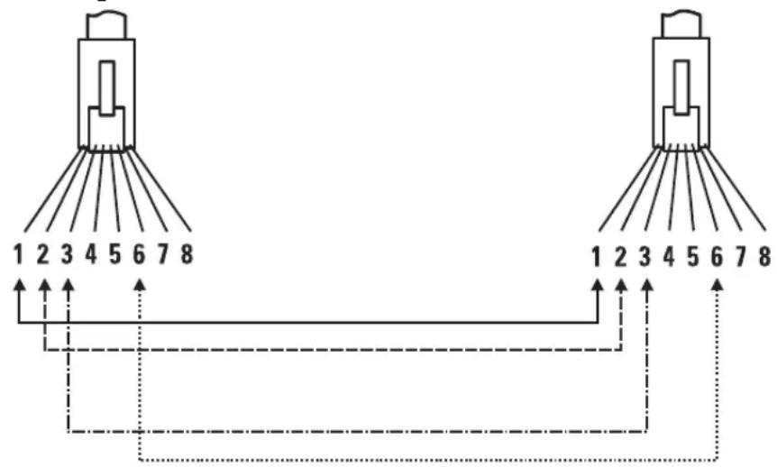
flowchart
graph TD
    A["Device 1"] -->|1 2 3 4 5 6 7 8| B["Data Bus"]
    C["Device 2"] -->|1 2 3 4 5 6 7 8| D["Data Bus"]
    B --> E["Data Bus"]
    D --> E
    style A fill:#f9f,stroke:#333
    style C fill:#f9f,stroke:#333
    style B fill:#ccf,stroke:#333
    style D fill:#ccf,stroke:#333
Note
Pins 1 and 2 on connector “A” must be wired as a twisted pair to pins 1 and 2 on connector “B”.
Pins 3 and 6 on connector “A” must be wired as a twisted pair to pins 3 and 6 on connector “B”.
Pins 4, 5, 7, and 8 are not used in this application, although they may be wired in the cable.
Pin Assignments
| Switch End (MDI-X) | Computer, Transceiver, or Other End |
| Signal Pins Pins Signal | |
| receive + 1 1 transmit + receive - 2 2 transmit - transmit + 3 3 receive + transmit - 6 6 receive | |
Crossover Twisted-Pair Cable for 10 Mbps or 100 Mbps Network Connection
The HP Auto-MDIX operation of the 10/100 ports on the switches also allows you to use crossover cables for all network connections, to PCs, servers or other end nodes, or to hubs or other switches.
If any of these ports are given a fixed configuration, for example 100 Mbps/Full Duplex, the ports operate as MDI-X ports, and crossover cables must be then used for connections to hubs or switches or other MDI-X network devices.
Cable Diagram
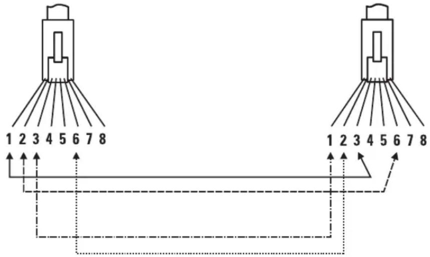
Note
Pins 1 and 2 on connector "A" must be wired as a twisted pair to pins 3 and 6 on connector "B".
Pins 3 and 6 on connector "A" must be wired as a twisted pair to pins 1 and 2 on connector "B".
Pins 4, 5, 7, and 8 are not used in this application, although they may be wired in the cable.
Pin Assignments
Switch End (MDI-X) Hub or Switch Port, or Other
MDI-X Port End
Signal Pins Pins Signal
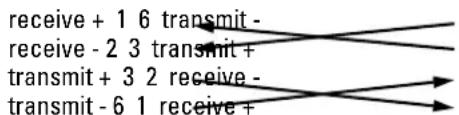
flowchart
graph LR
    A["receive + 1 6 transmit -"] --> B["receive - 2 3 transmit +"]
    B --> C["transmit + 3 2 receive -"]
    C --> D["transmit - 6 1 receive +"]
Straight-Through Twisted-Pair Cable for 1000 Mbps Network Connections
1000Base-T connections require that all four pairs or wires be connected.
Cable Diagram
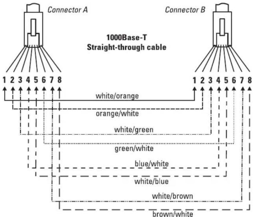
flowchart
graph TD
    A["Connector A"] -->|1 2 3 4 5 6 7 8| B["1000Base-T Straight-through cable"]
    C["Connector B"] -->|1 2 3 4 5 6 7 8| B
    B --> D["white/orange"]
    B --> E["orange/white"]
    B --> F["white/green"]
    B --> G["green/white"]
    B --> H["blue/white"]
    B --> I["white/blue"]
    B --> J["white/brown"]
    B --> K["brown/white"]
Note
Pins 1 and 2 on connector "A" must be wired as a twisted pair to pins 1 and 2 on connector "B".
Pins 3 and 6 on connector "A" must be wired as a twisted pair to pins 3 and 6 on connector "B".
Pins 4 and 5 on connector "A" must be wired as a twisted pair to pins 4 and 5 on connector "B".
Pins 7 and 8 on connector "A" must be wired as a twisted pair to pins 7 and 8 on connector "B".
Pin Assignments
For 1000Base-T operation, all four pairs of wires are used for both transmit and receive.
— This page is intentionally unused. —
Safety and EMC Regulatory Statements
Safety Information

WARNING
Documentation reference symbol. If the product is marked with this symbol, refer to the product documentation to get more information about the product.
A WARNING in the manual denotes a hazard that can cause injury or death.
CAUTION A CAUTION in the manual denotes a hazard that can damage equipment.
Do not proceed beyond a WARNING or CAUTION notice until you have understood the hazardous conditions and have taken appropriate steps.
Grounding
These are safety class I products and have protective earthing terminals. There must be an uninterruptible safety earth ground from the main power source to the product's input wiring terminals, power cord, or supplied power cord set. Whenever it is likely that the protection has been impaired, disconnect the power cord until the ground has been restored.
For LAN cable grounding:
■ If your LAN covers an area served by more than one power distribution system, be sure their safety grounds are securely interconnected.
■ LAN cables may occasionally be subject to hazardous transient voltages (such as lightning or disturbances in the electrical utilities power grid). Handle exposed metal components of the network with caution.
Servicing
There are no user-serviceable parts inside these products. Any servicing, adjustment, maintenance, or repair must be performed only by service-trained personnel.
These products do not have a power switch; they are powered on when the power cord is plugged in.
Safety Information (Japan)
安全性の考慮
安全記号

EMC Regulatory Statements
U.S.A.
FCC Class A
This equipment has been tested and found to comply with the limits for a Class A digital device, pursuant to Part 15 of the FCC Rules. These limits are designed to provide reasonable protection against interference when the equipment is operated in a commercial environment. This equipment generates, uses, and can radiate radio frequency energy and, if not installed and used in accordance with the instruction manual, may cause interference to radio communications. Operation of this equipment in a residential area may cause interference in which case the user will be required to correct the interference at his own expense.
Canada
This product complies with Class A Canadian EMC requirements.
Australia/New Zealand

This product complies with Australia/New Zealand EMC Class A requirements.
Japan
VCCI Class A
Regulatory Model Identification Number
For regulatory identification purposes, the HP ProCurve Series 4100gl Switches are assigned a Regulatory Model Number. The Regulatory Model Number for these switches is RSVLC-0201.
This regulatory number should not be confused with the marketing name (HP ProCurve Series 4100gl Switches), or product numbers (J4861A, J4865A, J4887A, J4888A)
European Community
DECLARATION OF CONFORMITY
according to ISO/IEC Guide 22 and EN45014
Manufacturer's Name: Hewlett-Packard Company
Manufacturer's Address: 8000 Foothills Blvd.
Roseville, CA 95747-5502
U.S.A.
declares that the product:
Product Name: HP ProCurve Switch 4108gl Bundle,
HP ProCurve Switch 4108gl,
HP ProCurve Switch 4104gl
Accessories: J4862B, J4863A, J4864A, J4893A, J4116A, J4131B,
J4132A, J4834A, J4853A, J4858A, J4859A, J4839A
J4908A, J4892A
Regulatory Model Number: RSVLC-0201
conforms to the following Product Specifications:
Safety: EN60950 (1992) +A1,A2,A3,A4,A11 / IEC 950 (1991) +A1,A2,A3,A4
EN60825-1 (1994) +A11 (1996) / IEC 825-1 (1993), Class 1
EMC: EN 55022 (1998) / CISPR-22 (1997) Class A
EN55024 (1998) / CISPR-24 (1997)
EN 61000-3-2 (2000) / IEC 61000-3-2 (2000) Harmonics
EN 61000-3-3 (1995) / IEC 61000-3-3 (1994) Flicker
Supplementary Information:
The product herewith complies with the requirements of the Low Voltage Directive
73/23/EEC and the EMC Directive 89/336/EEC and carries the CE mark.
Tested with Hewlett-Packard Co. products only.
Roseville, October 24, 2003

Mike Avery,
Regulatory Engineering Manager
European Contact: Your local Hewlett-Packard Sales and Service Office or Hewlett-Packard GmbH,
Department TRE, Herrenberger Strasse 140, D-71034 Böblingen (FAX:+49-7031-14-3143).
Index
Numerics
100/1000Base-T
note on cable requirements ... B-2
ports, cables used with ... B-2
twisted-pair cable specifications ... B-2
1000Base-LH
connections, length limitations ... 2-6
ports, cables used with ... 2-6
1000Base-LX
connections, length limitations ... 2-6
ports, cables used with ... 2-6
1000Base-SX
connections, length limitations ... 2-6
ports, cables used with ... 2-6
1000Base-T
connections, length limitations ... 2-5
ports, cables used with ... 2-5
100Base-TX
ports, cables used with ... B-2
twisted-pair cable specifications ... B-2
10Base-T
ports, cables used with ... B-2
twisted-pair cable specifications ... B-2
A
Act LED ... 1-6
auto MDI/MDI-X operation ... B-5, B-7
HP Auto-MDIX feature ... B-3
B
back of switch
description ... 1-9
power connector ... 1-9
slot for redundant power supply ... 1-9
basic connectivity, example topology ... 2-22
basic switch configuration
IP address ... 3-3
manager password ... 3-2
subnet mask ... 3-3
Switch Setup screen ... 3-2
Bootp
automatic switch configuration ... 3-2
for in-band console access ... 2-19
buttons
Clear button ... 1-8
LED Mode Select button ... 1-7
Reset button ... 1-8
C
cabinet
mounting the switch in ... 2-13
note on mounting screws ... 2-16
cables
100/1000Base-T
cable specifications ... B-2
note on cable requirements ... B-2
1000Base-LH
connections ... 2-6
fiber-optic cable specifications ... B-3
1000Base-LX
connections ... 2-6
fiber-optic cable specifications ... B-3
1000Base-SX
connections ... 2-6
fiber-optic cable specifications ... B-3
1000Base-T connections ... 2-5
100Base-TX
cable specifications ... B-2
10Base-T
cable specifications ... B-2
connecting cables to switch ports ... 2-18
effects of non-standard cables ... 4-1
fiber-optic, specifications ... B-3
infrastructure requirements ... 2-5
length limitations ... 2-5
required types ... 2-5
serial for direct console connection ... 2-20
cables, twisted pair
category 3, 4, 5 ... B-4
connector pin-outs ... B-3
crossover cable pin-out ... B-6
HP Auto-MDIX feature ... B-3
MDI-X to MDI connections ... B-5, B-7
MDI-X to MDI-X connections ... B-6
note on requirements for 1000Base-T ... B-2
pin-outs ... B-5, B-7
specifications ... B-2
straight-through cable pin-out ... B-5, B-7
switch-to-computer connection ... B-5, B-7
switch-to-switch or hub connection ... B-6
wiring rules ... B-4
cabling infrastructure ... 2-5
Clear button
deleting passwords ... 1-8
description ... 1-8
location on switch ... 1-4, 1-8
restoring factory default configuration ... 1-8, 4-12
to delete password protection ... 3-4
CLI prompt, console
displaying ... 2-20
configuration
checking when troubleshooting ... 4-3
DHCP/Bootp ... 3-2
IP address ... 3-3
IP address, manually ... 3-3
manager password ... 3-2
restoring factory defaults ... 1-8, 4-12
subnet mask ... 3-3
Switch Setup screen ... 3-2
connecting the switch to a power source ... 2-18
connector specifications ... A-3
console
checking messages during
troubleshooting ... 4-10
displaying the CLI prompt ... 2-20
features ... 2-19
how to connect in-band ... 2-19
how to connect out-of-band ... 2-19
serial cable connection ... 2-20
Switch Setup screen ... 3-2
telnet access ... 2-20, 3-5
terminal configuration ... 2-19
console port
description ... 1-8
location on switch ... 1-4
crossover cable
pin-out ... B-6
use with fixed port configurations ... B-4
D
deleting passwords ... 1-8
description
back of switches ... 1-9
front of switches ... 1-4
LEDs ... 1-5
DHCP
automatic switch configuration ... 3-2
for in-band console access ... 2-19
diagnostic tests ... 4-10
checking the console messages ... 4-10
checking the LEDs ... 4-4, 4-10
end-to-endconnectivity...4-11
testing the switch only ... 4-10
testing twisted-pair cabling ... 4-11
downloading new code ... 4-13
E
edge switch, example topology as ... 2-23
electrical specifications ... A-1
EMC regulatory statements ... C-8
environmental specifications ... A-2
equipment cabinet
mounting the switch in ... 2-13
note on mounting screws ... 2-16
example network topologies ... 2-22
as an edge switch ... 2-23
basic connectivity ... 2-22
switch stacking ... 2-24
F
factory default configuration, restoring ... 1-8, 4-12
Fan Status LED ... 1-5
showing error conditions ... 4-4
Fault LED
behavior during self test ... 2-12
description ... 1-5
flashing definition ... 1-6
location on switch ... 1-4
showing error conditions ... 4-4
FDx LED ... 1-6
features
console ... 2-19
Series 4100GL Series ... 1-10
fiber-optic cables ... B-3
1000Base-LH ... B-3
1000Base-LX ... B-3
1000Base-SX ... B-3
flashing LEDs
error indications ... 4-4
front of switch
Clear button ... 1-8
console port ... 1-8
description ... 1-4
LEDs ... 1-5
Mode Select button and indicator LEDs ... 1-7
Reset button ... 1-8
full-duplex fixed configuration
effects on network connections ... 4-3
G
Gigabit-LH
ports, cables used with ... B-3
Gigabit-SX
ports, cables used with ... B-3
Gigbit-LX
ports, cables used with ... B-3
H
horizontal surface, mounting switch on ... 2-16
hot swapping
mini-GBICs ... 1-10
redundant power supply ... 1-9, 2-9
resetting the switch for new module type ... 2-21
switch modules ... 1-10, 2-21
transceivers ... 1-10
HP Auto-MDIX
feature description ... B-3
I
in-band
console access, types of ... 2-19
managing the switch ... 3-1
included parts ... 2-1
installation
connecting the switch to a power source ... 2-18
horizontal surface mounting ... 2-16
network cable requirements ... 2-5
optional modules ... 2-7
precautions ... 2-3, 2-4
rack or cabinet mounting ... 2-13
redundant power supply ... 2-9
site preparation ... 2-5
summary of steps ... 2-2
Switch 4108GL ... 2-1
wall mounting ... 2-17
IP address
configuring ... 3-3
using for switch management ... 3-5
L
LED Mode Select
button ... 1-7
indicator LEDs ... 1-6, 1-7
LEDs
Act...1-6
behavior during self test ... 2-12
checking during troubleshooting ... 4-10
descriptions of ... 1-5
error indications ... 4-4
Fan Status ... 1-5
showing error conditions ... 4-4
Fault ... 1-5
behavior during self test ... 2-12
showing error conditions ... 4-4
FDx ... 1-6
flashing definition ... 1-6
Link ... 1-6
Max ... 1-6
Mode
description ... 1-6
selecting the display ... 1-7
mode select indicators ... 1-6
Module Status ... 1-6
showing error conditions ... 4-4
on switch chassis ... 1-5
on switch modules ... 1-6
Power...1-5
behavior during error conditions ... 4-4
behavior during self test ... 2-12
Power Status ... 1-5
behavior during self test ... 2-12
showing error conditions ... 4-4
Self Test ... 1-5
behavior during self test ... 2-12
showing error conditions ... 4-4
length limitations
1000Base-LH connections ... 2-6
1000Base-LX connections ... 2-6
1000Base-SX connections ... 2-6
1000Base-T connections ... 2-5
Link LEDs ... 1-6
link test ... 4-11
M
Max LED ... 1-6
MDI-X to MDI network cable ... B-5, B-7
MDI-X to MDI-X network cable ... B-6
mini-GBICs
hot swap feature ... 1-10
indications of unsupported ... 4-7
supported types ... 1-10
Mode LEDs
description ... 1-6
selecting the display ... 1-7
module hot swap feature ... 1-10
module slots
location on switch ... 1-4
Module Status LEDs ... 1-6
showing error conditions ... 4-4
modules, switch
hot swapping ... 2-21
installing ... 2-7
LEDs ... 1-6
list of available types ... 1-10
mounting the switch
in a rack or cabinet ... 2-13
precautions ... 2-3, 2-4
on a horizontal surface ... 2-16
on a wall ... 2-17
precautions ... 2-17
N
network cables
1000Base-LH connections ... 2-6
1000Base-LX connections ... 2-6
1000Base-SX connections ... 2-6
1000Base-T connections ... 2-5
fiber-optic, specifications ... B-3
HP Auto-MDIX feature ... B-3
required types ... 2-5
twisted-pair connector pin-outs ... B-3
twisted-pair, specifications ... B-2
twisted-pair, wiring rules ... B-4
network devices
connecting to the switch ... 2-18
network ports
connecting to ... 2-18
LEDs for ... 1-6
standards compliance ... A-3
types of ... 2-5
network topologies, examples of ... 2-22
non-standard network cables, effects ... 4-1
0
out-of-band console access ... 2-19, 3-5
P
parts included with the switch ... 2-1
passwords
configuring ... 3-2
deleting ... 1-8
deleting with the Clear button ... 3-4
if you lose the password ... 3-4
physical specifications, switch ... A-1
Ping test ... 4-11
pin-outs, twisted-pair cables ... B-3
port configuration
checking when troubleshooting ... 4-3
port LEDs
Link ... 1-6
Mode ... 1-6
ports
console ... 2-19
HP Auto-MDIX feature ... B-3
network connections ... 2-18
power connector ... 1-9
Power LED
behavior during error conditions ... 4-4
behavior during self test ... 2-12
description ... 1-5
location on switch ... 1-4
Power Status LEDs ... 1-5
behavior during self test ... 2-12
showing error conditions ... 4-4
power supply
connecting to a power source ... 2-18
installation cautions ... 1-9, 2-9
making redundant power connections ... 2-18
precautions
installing power supply ... 1-9, 2-9
mounting the switch in a rack or cabinet ... 2-3, 2-4
mounting the switch on a wall ... 2-17
power requirements ... 2-3, 2-4
preparing the installation site ... 2-5
Proactive Network tools
diagnostics with ... 4-9
R
rack
mounting the switch in ... 2-13
rebooting the switch
to initialize changed module type ... 2-7
redundant power connections ... 2-18
redundant power supply
installation cautions ... 1-9, 2-9
installing ... 2-9
slot for installing ... 1-9
regulatory statements ... C-8
Reset button
description ... 1-8
location on switch ... 1-4, 1-8
restoring factory default configuration ... 4-12
resetting the switch
factory default reset ... 4-12
for module hot swap ... 2-21
location of Reset button ... 1-8
troubleshooting procedure ... 4-10
S
safety and regulatory statements ... C-1
safety specifications ... A-3
selecting the Mode LED display ... 1-7
self test
Fault LED behavior ... 2-12
LED behavior during ... 2-12
Power LED behavior ... 2-12
Self Test LED behavior ... 2-12
Self Test LED
behavior during factory default reset ... 4-12
behavior during self test ... 2-12
description ... 1-5
showing error conditions ... 4-4
serial cable
for direct console connection ... 2-20
slots for modules
location on switch ... 1-4
specifications
connectors ... A-3
electrical ... A-1
environmental ... A-2
physical ... A-1
safety ... A-3
stacking the switches ... 2-24
straight-through cable
pin-out ... B-5, B-7
use with fixed port configurations ... B-4
subnet mask, configuring ... 3-3
summary
of cables used with the switch ... 2-5
of switch installation ... 2-2
supported mini-GBICs ... 1-10
supported switch modules ... 1-10
supported transceivers ... 1-10
switch
connecting to a power source ... 2-18
description ... 1-1
electrical specifications ... A-1
environmental specifications ... A-2
features ... 1-10
front panel description ... 1-4
included parts ... 2-1
mounting in a rack or cabinet ... 2-13
mounting on a horizontal surface ... 2-16
mounting on a wall ... 2-17
physical specifications ... A-1
switch chassis
LED descriptions ... 1-5
switch modules
booting the switch to initialize changed module type ... 2-7
hot swapping ... 2-21
installing ... 2-7
LEDs descriptions ... 1-6
list of available types ... 1-10
switch operation
verifying after installation ... 2-11
Switch Setup screen ... 3-2
configuring a subnet mask ... 3-3
configuring an IP address ... 3-3
field descriptions ... 3-3
switch stacking
topology with ... 2-24
T
telnet access to the console ... 2-20, 3-5
terminal configuration ... 2-19
testing
checking the console messages ... 4-10
checking the LEDs ... 4-10
diagnostic tests ... 4-10
end-to-end communications ... 4-11
link test ... 4-11
Ping test ... 4-11
switch operation ... 4-10
switch-to-device communications ... 4-11
twisted-pair cabling ... 4-11
tips for troubleshooting ... 4-1
topologies
effects of improper topology ... 4-2
examples of ... 2-22
as an edge switch ... 2-23
basicconnectivity...2-22
switch stacking ... 2-24
transceivers
hot swap feature ... 1-10
supported types ... 1-10
troubleshooting ... 4-1
basic tips ... 4-1
checking port configuration ... 4-3
checking the console messages ... 4-10
checking the LEDs ... 4-10
common network problems ... 4-1
connecting to fixed full-duplex devices ... 4-3
diagnostic tests ... 4-10
effects of improper topology ... 4-2
effects of non-standard cables ... 4-1
link test ... 4-11
Ping test ... 4-11
Proactive Network tools ... 4-9
restoring factory default configuration ... 4-12
testing connections to other devices ... 4-11
testing end-to-end communications ... 4-11
testing the switch ... 4-10
testing the twisted-pair cables ... 4-11
unsupported mini-GBICs ... 4-7
twisted-pair cable ... B-2
crossover cable pin-out ... B-6
pin-outs ... B-3, B-5, B-7
straight-through cable pin-out ... B-5, B-7
switch-to-computer connection ... B-5, B-7
switch-to-switch or hub connection ... B-6
testing ... 4-11
twisted-pair ports
HP Auto-MDIX feature ... B-3
V
VT-100 terminal
serial cable connection for ... 2-20
W
wall
mounting switch on ... 2-17
wiring rules for twisted-pair cables ... B-4

Technical information in this document is subject to change without notice.
©Copyright 2002, 2003
Hewlett-Packard Development Company, L.P. Reproduction, adaptation, or translation without prior written permission is prohibited except as allowed under the copyright laws.
Printed in Singapore
November 2003
Manual Part Number
5990-6048

- HP ProCurve Series 4100gl Switches
- Publication Number
- Applicable Products
- Disclaimer
- Warranty
- Safety
- Contents
- Introducing the HP ProCurve Series 4100gl Switches
- Installing the Series 4100gl Switches
- Getting Started With Switch Configuration
- Troubleshooting
- A Specifications
- B Switch Ports and Network Cables
- C Safety and EMC Regulatory Statements
- Index
- Introducing the HP ProCurve Series 4100gl Switches
- Front of the Switch
- LEDs
- Table 1-2. Switch Module LEDs
- LED Mode Select Button and Indicator LEDs
- Console Port
- Reset Button
- Clear Button
- Back of the Switch
- Power Connector
- Slot for Redundant Power Supply
- Caution
- Caution:
- Switch Features
- Installing the Series 4100gl Switches
- Included Parts
- Installation Procedures
- Summary
- Warnings
- Installation Precautions
- Installation Precautions (continued)
- Cautions
- Prepare the Installation Site
- Cabling Infrastructure
- Installation Location
- Install Switch Modules
- Note
- Module Installation Notes
- Installing the Series 4100gl Switches Installation Procedures
- (Optional) Install Second Power Supply
- Verify the Switch Passes Self Test
- LED Behavior:
- During the self test:
- When the self test completes successfully:
- Mount the Switch
- Rack or Cabinet Mounting
- Equipment Cabinet Note
- Horizontal Surface Mounting
- Wall Mounting
- Connect the Switch to a Power Source
- Connect the Network Devices
- Condition Diagnostic Tip
- Port LED is still off when a cable is connected
- (Optional) Connect a Console to the Switch
- Terminal Configuration
- Direct Console Access
- Telnet Console Access
- Hot Swapping Switch Modules
- Adding or Replacing Modules
- Changing the Module Type
- Example Network Topologies
- Basic Connectivity
- Stacking the Switches
- Getting Started With Switch Configuration
- Recommended Minimal Configuration
- Using the Switch Setup Screen
- HP Procurve Switch 4104GL#
- Where to Go From Here
- Using the IP Address for Remote Switch Management
- Starting a Telnet Session
- HP Procurve Switch 4108GL#
- Starting a Web Browser Session
- Troubleshooting
- Basic Troubleshooting Tips
- Troubleshooting Basic Troubleshooting Tips
- ■ Connecting to devices that have a fixed full-duplex configuration.
- Diagnosing with the LEDs
- Proactive Networking
- Hardware Diagnostic Tests
- Testing the Switch by Resetting It
- Checking the Switch LEDs
- Checking Console Messages
- Testing Twisted-Pair Cabling
- Testing Switch-to-Device Network Communications
- Testing End-to-End Network Communications
- Restoring the Factory Default Configuration
- Downloading New Code
- HP Customer Support Services
- Before Calling Support
- Information Item Information Location
- Physical
- Height:
- Weight:
- Electrical
- Acoustic
- Network Connectors
- Switch Ports and Network Cables
- Switch Ports
- Twisted Pair
- Fiber-Optic
- Cables
- Twisted-Pair Cable/Connector Pin-Outs
- Other Wiring Rules:
- Straight-Through Twisted-Pair Cable for 10 Mbps or 100 Mbps Network Connections
- Crossover Twisted-Pair Cable for 10 Mbps or 100 Mbps Network Connection
- Pin Assignments
- Straight-Through Twisted-Pair Cable for 1000 Mbps Network Connections
- Safety and EMC Regulatory Statements
- Safety Information
- Grounding
- Servicing
- Safety Information (Japan)
- EMC Regulatory Statements
- Canada
- Australia/New Zealand
- Japan
- Regulatory Model Identification Number
- European Community
- DECLARATION OF CONFORMITY
- Numerics
- A
- B
- C
- D
- E
- F
- Fault LED
- FDx LED ... 1-6
- features
- fiber-optic cables ... B-3
- flashing LEDs
- front of switch
- full-duplex fixed configuration
- G
- Gigabit-LH
- Gigabit-SX
- Gigbit-LX
- H
- hot swapping
- HP Auto-MDIX
- I
- in-band
- included parts ... 2-1
- installation
- IP address
- L
- LED Mode Select
- M
- N
- 0
- P
- R
- S
- T
- V
- W
Brand : HP
Model : ProCurve 4100gl
Category : Network switch