
1820-48G-PoE+ - Network switch HP - Free user manual and instructions
Find the device manual for free 1820-48G-PoE+ HP in PDF.


| Product Type | Network Switch |
| Model | HP 1820-48G-PoE+ |
| Ports | 48 x Gigabit Ethernet (10/100/1000) PoE+; 4 x SFP (shared) |
| PoE Budget | 370W |
| Switching Capacity | 104 Gbps |
| Forwarding Rate | 77.4 Mpps |
| Management | Web-based GUI, SNMP v1/v2c/v3, CLI via console (optional) |
| VLAN Support | 802.1Q VLAN (up to 256 VLANs) |
| QoS | 802.1p prioritization, traffic shaping |
| Dimensions (W x D x H) | 17.4 x 8.7 x 1.7 in (44.2 x 22.1 x 4.3 cm) |
| Weight | 6.8 kg (15.0 lb) |
| Power Supply | Internal, 100-240 VAC, 50/60 Hz |
| Power Consumption | Maximum 440W (with full PoE load) |
| Cooling | Internal fan(s), side-to-side airflow |
| Operating Temperature | 32°F to 113°F (0°C to 45°C) |
| Safety Standards | UL, CE, FCC Class A |
| Mounting | Rackmount (1U) with included brackets |
| Cleaning Instructions | Wipe with a dry, lint-free cloth; avoid liquids |
| Spare Parts Availability | Power supply unit (PSU) and fan modules available from HP |
| Repairability | Limited user-serviceable; professional service recommended for PSU/fan replacement |
Frequently Asked Questions - 1820-48G-PoE+ HP
User questions about 1820-48G-PoE+ HP
0 question about this device. Answer the ones you know or ask your own.
Ask a new question about this device
Download the instructions for your Network switch in PDF format for free! Find your manual 1820-48G-PoE+ - HP and take your electronic device back in hand. On this page are published all the documents necessary for the use of your device. 1820-48G-PoE+ by HP.
USER MANUAL 1820-48G-PoE+ HP
Management and Configuration Guide
© Copyright 2015, 2016 Hewlett Packard Enterprise Development, L.P. The information contained herein is subject to change without notice. All Rights Reserved.
This document contains proprietary information, which is protected by copyright. No part of this document may be photocopied, reproduced, or translated into another language without the prior written consent of Hewlett-Packard.
Publication Number
5998-7651a
October 2016
Applicable Products
HP 1820-8G Switch J9979A
HP 1820-8G-PoE+ Switch J9982A
HP 1820-24G Switch J9980A
HP 1820-24G-PoE+ Switch J9983A
HP 1820-48G Switch J9981A
HP 1820-48G-PoE+ Switch J9984A
Trademark Credits
Microsoft®, Windows®, and Windows NT® are US registered trademarks of Microsoft Corporation. Java™ is a US trademark of Sun Microsystems, Inc.
Open Source Code Notice
Open Source Software shall mean those portions of the software that were made available to HP pursuant to, and may only be distributed pursuant to, the GNU General Public License* or a similar license that prohibits distribution of Open Source Software or derivative works of the Open Source Software on alternative terms.
HP makes such Open Source Software available to you pursuant to the same terms on which such Open Source Software was made available to HP and on no other or additional terms.
The Open Source Software modules and "make" files contained in the Software are available for HP in the form of a compact disk (CD). The CD includes the "original package" (original source files plus the "make" files) as well as a "patch" file that accounts for the modification made from the original source code. To receive the CD, HP charges a small fee in order to cover the actual costs of manufacturing and shipping the CD.
The information contained herein is subject to change without notice.
Disclaimer
The information contained herein is subject to change without notice. The only warranties for Hewlett Packard Enterprise products and services are set forth in the express warranty statements accompanying such products and services. Nothing herein should be construed as constituting an additional warranty. Hewlett Packard Enterprise shall not be liable for technical or editorial errors or omissions contained herein.
Confidential computer software. Valid license from Hewlett Packard Enterprise required for possession, use, or copying. Consistent with FAR 12.211 and 12.212, Commercial Computer Software, Computer Software Documentation, and Technical Data for Commercial Items are licensed to the U.S. Government under vendor's standard commercial license.
Warranty
For HPE networking warranty information, visit www.hpc.com/networking/warranty
A copy of the specific warranty terms applicable to your Hewlett Packard Enterprise products and replacement parts can be obtained from your HPE Sales and Service Office or authorized dealer.
Preface
About This Document
HP 1820 series switches provide reliable, plug-and-play Gigabit network connectivity. As the follow-on to the popular HP Switch 1810 series, the HP 1820 series switches provide extended power-over-Ethernet capabilities, support additional networking protocols such as LLDP-MED and IGMP snooping, and provide enhanced switch management capabilities. The HP 1820 series switches are ideal for open offices that require silent operation or businesses making the transition from unmanaged to managed networks.
The HP 1820 series switches can be managed in-band from a remote network station using a web-based graphical user interface (GUI), and its configuration may also be viewed using the SNMP manager. This guide describes how to configure and view the software features using the web GUI.
Audience
The information in this guide is primarily intended for system administrators and support providers who are responsible for configuring, operating, or supporting a network using HP 1820 series switch software. An understanding of the software specifications for the networking device platform, and a basic knowledge of Ethernet and networking concepts, are presumed.
About Your Switch Manual Set
The switch manual set includes the following:
■ Quick Setup Guide - a printed guide shipped with your switch. Provides illustrations for basic installation and setup guidelines. ■ Regulatory and Safety Information - printed documentation shipped with your switch. Includes Regulatory statements and standards supported by the switch, along with product specifications. ■ Installation and Getting Started Guide - (HP web site only). Provides detailed installation guide for your switch, including physical installation on your network, basic troubleshooting, product specifications, supported accessories, Regulatory and Safety information. ■ Management and Configuration Guide - This guide describes how to manage and configure switch features using a web browser interface. ■ Release Notes - (HP web site only). Provides information on software updates. The Release Notes describe new features, fixes, and enhancements that become available between revisions of the above guides.
Note
For the latest version of all HPE documentation, visit the HPE web site at www.hpe.com/networking/support. Then select your switch product.
Supported Features
HP 1820 series switches include support for the following features:
| Feature 1820 Series Switches | |
| HTTP and HTTPS sessions 4 each, 8 totalSNMP v1/v2c (read-only) community 1MAC table 8000 entries for 8- and 24-portSNTP server configuration 1 | switches; 16000 entries for 48-port switches |
| Time zones count 91Jumbo frame size 9216 bytesSoft session web session timeout 1 min–60 minHard session web session timeout 1 Hr–168 Hrs | |
| Trunk configuration (1820-8G/1820-8G-PoE+) | 4 |
| Trunk configuration (1820-24G/1820-24G-PoE+) | 8 |
| Trunk configuration (1820-48G) 16 | |
| Trunk membership ports (1820-8G/1820-8G-PoE+/1820-24G/1820-24G-PoE+) | 4 |
| Trunk membership ports (1820-48G) 8 | |
| VLANs 64VLAN IDs 1-4093VLAN priority levels 0–7Syslog servers 1 | |
| Buffered logs | 100 (total storage 10K) |
| Maintenance users | 1 |
| Password length | 8 chars–64 chars |
| Images | 2 |
Contents
Preface
About This Document .... iii
About Your Switch Manual Set .... iii
Supported Features ....iv
1 Getting Started
Connecting the Switch to a Network 1-1
Operating System and Browser Support 1-2
Getting Started With the Web Interface 1-3
Logging On.... 1-3
Interface Layout and Features 1-4
Common Page Elements 1-5
Saving Changes 1-5
Graphical Switch 1-5
2 Dashboard
3 Setup Network
Get Connected 3-1
System Time Pages 3-4
Time Zone Summary 3-4
Time Configuration 3-6
Time Zone Configuration 3-8
Daylight Saving Time Configuration 3-9
4 Switching Features
Port Configuration 4-1
Port Status 4-1
Port Summary Statistics 4-3
Port Mirroring 4-5
Jumbo Frames 4-7
Flow Control 4-8
Spanning Tree 4-9
Global STP Settings and Port Status 4-10
Port STP Settings 4-13
Loop Protection 4-16
Loop Protection Status 4-16
Loop Protection Configuration 4-17
IGMP Snooping 4-20
5 Virtual LAN
Viewing VLAN Status and Adding VLANs 5-1
Adding VLANs 5-2
Changing a VLAN Name 5-2
Configuring Interfaces as VLAN Members 5-3
VLAN Port Configuration 5-4
6 Trunks
Trunk Configuration 6-1
Modifying Trunk Settings 6-2
Trunk Statistics 6-4
7 Link Layer Discovery Protocol (LLDP and LLDP-MED)
LLDP Global Configuration 7-1
LLDP Local Device Summary 7-4
Displaying Port Details 7-5
LLDP Remote Device Summary 7-6
LLDP Global Statistics 7-7
LLDP-MED Global Configuration 7-9
LLDP-MED Local Device Summary 7-11
LLDP-MED Remote Device Summary 7-12
Displaying Remote Device Details 7-12
8 Power Over Ethernet
PoE Capabilities 8-1
PoE Configuration 8-2
PoE Port Configuration 8-3
Modifying Port PoE Settings 8-4
Viewing PoE Port Details 8-5
PoE Port Schedule 8-6
Configuring an Absolute Time Period 8-7
Adding a Periodic Time Period 8-8
9 Security
Advanced Security Configuration 9-1
Secure Connection 9-3
Uploading SSL Certificates and Encryption Files 9-5
10 Green Features
Green Features Configuration 10-1
EEE Status 10-3
11 Diagnostics
Buffered Log 11-1
Log Configuration 11-3
Ping Test 11-5
Reboot Switch 11-6
Factory Defaults 11-6
Support File 11-7
Locator 11-8
MAC Table 11-9
12 Maintenance Pages
Password Manager 12-1
Backup and Update Manager 12-2
Backing Up Files 12-2
Updating Files 12-3
Dual Image Configuration 12-5
Getting Started
This chapter describes how to make the initial connections to the switch and provides an overview of the web interface.
Connecting the Switch to a Network
To enable remote management of the switch through a web browser, the switch must be connected to the network. The switch is preconfigured with an IP address for management purposes. After initial configuration, the switch can also be configured to acquire its address from a DHCP server on the network.
By default, the switch is assigned the following static IP information for access to the web interface:
■ IP address: 192.168.1.1 ■ Network mask: 255.255.255.0 ■ Gateway: 0.0.0.0
- Connect the switch to the management PC or to the network using any of the available network ports.
- Power on the switch.
- Set the IP address of the management PC's network adaptor to be in the same subnet as the switch.
Example: Set it to IP address 192.168.1.2, mask 255.255.255.0.
- Enter the IP address shown above in the web browser. See page 1-3 for web browser requirements.
Thereafter, use the web interface to configure a different IP address or configure the switch as a DHCP client so that it receives a dynamically assigned IP address from the network.
Note
If you enable DHCP for IP network configuration, the switch must be connected to the same network as the DHCP server. You will need to access your DHCP server to determine the IP address assigned to the switch. ■ The switch supports LLDP (Link Layer Discovery Protocol), allowing discovery of its IP address from a connected device or management station. If DHCP is used for configuration and the switch fails to be configured, the IP address 192.168.1.1 is assigned to the switch interface.
After the switch is able to communicate on your network, enter its IP address into your web browser's address field to access the switch management features.
Operating System and Browser Support
The following operating systems and browsers with JavaScript enabled are supported:
Operating System Browser
| Windows 7 Internet Explorer 9, 10 | |
| Firefox 25 | |
| Chrome 30 | |
| Windows 8 Internet Explorer 10 | |
| Firefox 25 | |
| Chrome 30 | |
| MacOS X 10.9 Firefox 25 | |
| Chrome 30 | |
| Safari 7 | |
Getting Started With the Web Interface
This section describes the following web pages:
■“Logging On” on page 1-3 ■“Interface Layout and Features” on page 1-4
Logging On
Follow these steps to log on through the web interface:
- Open a web browser and enter the IP address of the switch in the web browser address field.
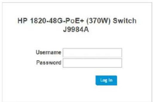
- On the Login page, enter the username and password (if one has been set), and then click Log In. By default, the username is admin and there is no password. After the initial log on, the administrator may configure a password.
Note
To set the password or change the username, see "Password Manager" on page 12-1.
Figure 1-1. Login Page
Support
Interface Layout and Features
Figure 1-2 shows the initial view. Figure 1-2. Interface Layout and Features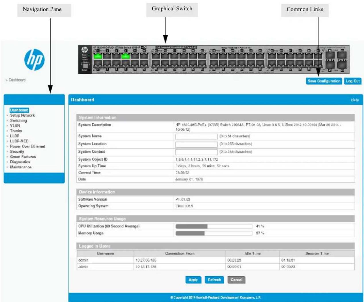
Click on any topic in the navigation page to display related configuration options.
The Dashboard page displays when you first log on and when you click Dashboard in the navigation pane. See "Dashboard" on page 2-1 for more information.
You can click the Setup Network link beneath Dashboard to display the Get Connected page, which you use to set up a management connection to the switch. See "Get Connected" on page 3-1 for more information.
The graphical switch displays summary information for the switch LEDs and port status. For information on this feature see "Graphical Switch" on page 1-5.
Getting Started
Getting Started With the Web Interface
Common Page Elements
- Click Help on any page to display a help panel that explains the fields and configuration options on the page.
- Click Apply to send the updated configuration to the switch. Applied changes update the device running configuration and take effect immediately. If you want the device to retain these changes across a reboot, you must first save the configuration. See “Saving Changes” on page 1-5. Click to refresh the page with the latest information from the switch.
- Click Cancel to clear any configuration changes that have not yet been applied on a page. Click to end the current management session.
Saving Changes
When you click Apply, changes are saved to the running configuration file in RAM. Unless you save them to system flash memory, the changes will be lost if the system reboots. To save them permanently, click Save Configuration on the upper right side of the page. Note that when there are unsaved changes, the button displays a file image. A page displays to confirm that you want to save, followed by a page that confirms that the operation was completed successfully.
Graphical Switch
The graphical switch, shown in Figure 1-3, displays at the top of the page as a representation of the physical switch to provide status information about individual ports. The graphical switch enables easy system configuration and web-based navigation.
You can right-click anywhere on the graphic and select from the menu to display the product information on the Dashboard page, to refresh the graphic display, and to set the automatic refresh rate.
Figure 1-3. Graphical Switch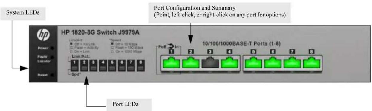
Port Configuration and Summary
You can point to any port to display the following information about the port:
The link status (up or down). Auto negotiation status. Speed and full-duplex/half-duplex settings.
The maximum transmission unit (MTU), which is the largest packet size that can be transmitted on the port.
You can left-click a port to display the Port Status page.
System LEDs
The following System LEDs reflect the status of the actual LEDs on the switch:
■ Power (Green)
- On — The switch is receiving power.
- Blinking — The switch is receiving power through its Power Over Ethernet (PoE) port. • Off — The switch is NOT receiving power.
■ Fault/Locator (Orange)
- Blinking rapidly — A fault has occurred, other than during self-test.
- Blinking slowly — The locator function has been enabled to help physically locate the switch.
- On — If continuously on, no firmware was detected upon boot-up.
- Off — The locator function is disabled and the switch is operating properly.
Port LEDs
Each 10/100/1000 Mbps RJ45 port has two single-color LEDs that reflect the status of the actual LEDs on the switch. The upper LED indicates the link/activity status and the lower LED indicates the mode (speed).
The Link/Act LED status can be one of the following:
■ On — A self-test is being performed on the port. ■ Blinking — The port has network activity. ■ Off — The port has no active network cable connected, is not receiving link signal, or is disabled.
The function of the Mode LED changes depending on whether the switch supports Power-Over-Ethernet:
■ When the switch supports PoE, the Mode LED indicates PoE status for port:
- On—PoE mode is enabled on the port.
- Blinking — The PoE port failed or is not currently providing power because it has temporarily exceeded its allocated power limit.
- Off—PoE mode is disabled on the port.
■ When the switch does not support PoE, the Mode LED indicates port speed:
• On—The port is operating continuously at 1000 Mbps. - Blinking —The port is operating at 100 Mbps. • Off—The port is operating at 10 Mbps.
Dashboard
You can use the Dashboard page to display and configure basic information about the system.
The Dashboard page displays basic information such as the configurable switch name and description, the IP address for management access, and the software and operating system versions. This page also shows resource usage statistics.
This page is displayed when you first log on or when you click Dashboard in the navigation pane.
Figure 2-1. Dashboard Page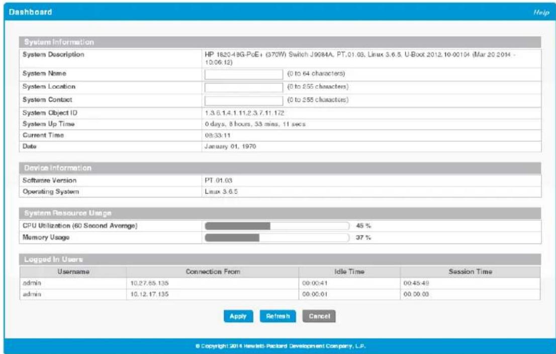
If you update the name, location, or contact information, click Apply to save any changes for the current boot session. The changes take effect immediately.
Table 2-1. Dashboard Page Fields
| Field Description | |
| System Information | |
| System Description | A description of the switch hardware, including the hardware type, software version, operating system version, and boot loader (U-Boot) version. |
| System Name | Enter the preferred name to identify this switch. A maximum of 64 alpha-numeric characters including hyphens, commas and spaces are allowed. This field is blank by default.The user configurable switch name will appear in the login screen banner. |
| System Location | Enter the location of this switch. A maximum of 255 alpha-numeric characters including hyphens, commas, and spaces are allowed. This field is blank by default. |
| System Contact | Enter the name of the contact person for this switch. A maximum of 255 alpha-numeric characters including hyphens, commas, and spaces are allowed. This field is blank by default. |
| System Object ID The base object ID for the switch's enterprise MIB. | |
| System Up Time | The time in days, hours and minutes since the last switch reboot. |
| Current Time | The current time in hours, minutes, and seconds as configured (24- or 12-hr AM/PM format) by the user. |
| Date The current date in month, day, and year format. | |
| Device Information | |
| Software Version The version of the code running on the switch. | |
| Operating System | The version of the operating system running on the switch. |
| System Resource Usage | |
| CPU Utilization | The percentage of CPU utilization for the entire system averaged over the past 60 seconds. |
| Memory Usage | The percentage of total system memory (RAM) currently in use. |
| Logged In Users—These fields display only when more than one user is logged into the management utility. | |
| Username | The username of each logged in user. |
| Connection From | The IP address from which the user logged in. |
| Idle Time | The time that has elapsed since the last user activity. |
| Session Time | The amount of time the user session has been active. |
Setup Network
You can use the Setup Network pages to configure how a management computer connects to the switch and how the switch connects to a server to synchronize its time.
Get Connected
Use the Get Connected page to configure settings for the network interface. The network interface is defined by an IP address, subnet mask, and gateway. Any one of the switch's front-panel ports can be selected as the management port for the network interface. The configuration parameters associated with the switch's network interface do not affect the configuration of the front-panel ports through which traffic is switched or forwarded except that, for the management port, the port VLAN ID (PVID) will be the management VLAN.
To display the Get Connected page, click Setup Network > Get Connected.
In the example configuration in Figure 3-1, the switch is configured to acquire its IP address through DHCP, which is the default setting. Access to the management software is restricted to members of VLAN 1.
Figure 3-1. Get Connected Page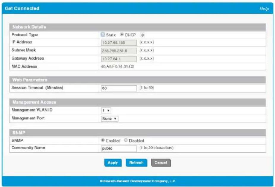
Table 3-1. Get Connected Fields
| Field Description | |
| Network Details | |
| Protocol Type Select the type of network connection:Static—Select this option to enable the IP address, subnet mask, and gateway fields for data entry.DHCP—Select this option to enable the switch to obtain IP information from a DHCP server on the network. If the DHCP server responds, then the assigned IP address is used. If DHCP is enabled but the DHCP server does not respond, the default static IP address 192.168.1.1 is used. DHCP operation is enabled by default.When a server assigns an IP address to the switch, it specifies the time for which the assignment is valid. After the time expires, the server may reclaim the address for assignment to another device. When DHCP is enabled, you can click to send a request to the DHCP server to renew the lease.Only a user-configured, static IP address is saved to flash.CAUTION:Changing the protocol type or IP address discontinues the current connection; you can log on again using the new IP information. | |
| IP Address The IPv4 address to be used. The default IP address is 192.168.1.1.Note:A broadcast IP address cannot be entered in this field. | |
| Subnet Mask | The IPv4 subnet address to be used. The default IP subnet address is 255.255.255.0. |
| Gateway Address | The IPv4 gateway address to be used. When in doubt, set this to be the same as the default gateway address used by your PC. |
| MAC Address | The burned-in universally administered MAC address of this switch. |
| Web Parameters | |
| Session Timeout | Specify the amount of time in minutes that a connection to the web interface remains active, assuming no user activity. The range is 1 to 60 and the default is 5 minutes. To keep the connection active regardless of user activity, set this value to 0.CAUTION:When a session window is closed without logging out, the server connection remains open until the session times out. When the session timeout is set to 0, closing a session window without logging out keeps the session open at the server indefinitely. In such cases, you may fail to connect after the maximum sessions are left open indefinitely. |
| Management Access | |
| Management VLAN ID | Access to the management software is controlled by the assignment of a management VLAN ID. Only ports that are members of the management VLAN allow access to the management software.By default, the management VLAN ID is 1. The allowed range is 1 to 4093. All ports are members of VLAN 1 by default; the administrator may want to create a different VLAN to assign as the management VLAN and associate it with a management port (see the next field). A VLAN that does not have any member ports (either tagged or untagged) cannot be configured as the management VLAN.When the network protocol is configured to be DHCP, any change in the configured management VLAN ID may cause disruption in connectivity because the switch acquires a new IP address when the management subnet is changed. To reconnect to the switch, the user must determine the new IP address by viewing the log on the DHCP server. |
Setup Network
Get Connected
| Field Description | |
| Management Port | Access to the management software can also be controlled by the selection of a management port. The selected management port is auto-configured to be an untagged member of the management VLAN and is excluded from any other untagged VLANs.When the switch boots with the default configuration, any port can be used as management port and this field is configured as 'None'.You can configure a management port to ensure that a port always remains an untagged member of the configured management VLAN; this helps to ensure management connectivity in case of an accidental change in VLAN membership.If no management port is specified, then all ports that are members of the management VLAN provide access to the switch management interface. If a management port is configured, access to the switch is restricted to that port. For example, if VLAN 1 is the management VLAN and port 10 is the management port, other ports that are members of VLAN 1 will not provide access to the switch management interface. |
| SNMP | |
| SNMP | Enable or disable Simple Network Management Protocol (SNMP). If enabled, the administrator can view switch data using an SNMPv1/v2c manager. The switch supports read-only access to a limited set of MIBs. SNMP is enabled by default. |
| Community Name | Specify a community name or use the default name, public.The switch supports the following MIBs:BRIDGE-MIB (IEEE 802.1Q)LLDP-MIB (IEEE 802.3AB)EtherLike-MIBIF - MIBRFC1213-MIBRMON-MIB (RMON History as in v1)Power Ethernet MIB (RFC3621), only on switches that support PoE+. (No SNMP information is available on configured PoE schedules.) |
Click Apply to save any changes for the current boot session. The changes take effect immediately.
Note
A power cycle does not reset the IP address to its factory-default value. If the configured IP address is unknown, you can perform a manual reset to factory defaults to regain access to the switch.
System Time Pages
You click Setup Network > System Time to display the web pages for configuring the system clock, SNTP client functionality, system time zone, and daylight saving time settings.
Time Zone Summary
The Time Zone Summary page displays the current time, time zone, and Daylight Saving Time settings, and enables you to configure the time display format. To display the Time Zone Summary page, click Setup Network > System Time in the navigation bar and ensure that the Clock tab is selected.
Figure 3-2. Time Zone Summary Page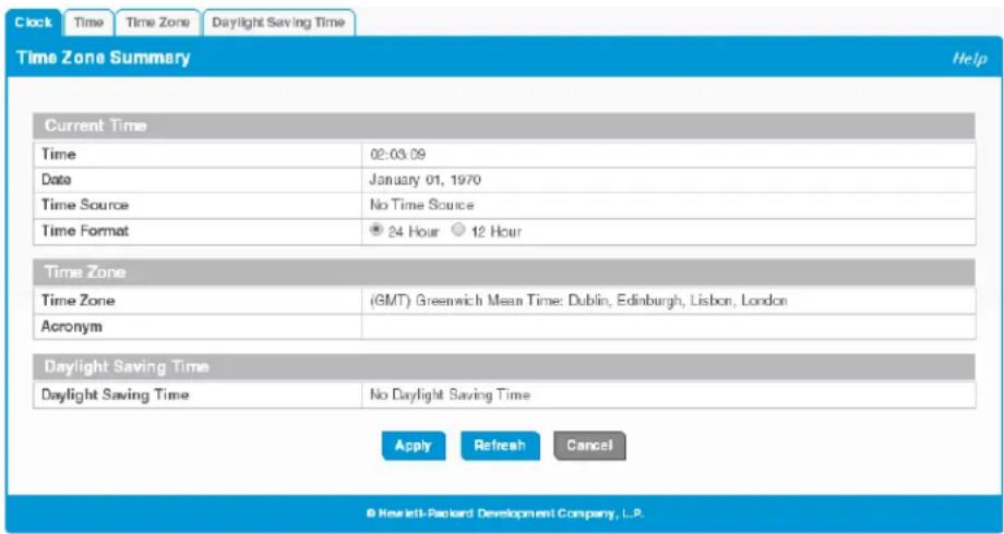
Table 3-2. Time Zone Summary Fields
| Field Description | |
| Current Time | |
| Time | The current time. This value is determined by an SNTP server. When SNTP is disabled, the system time increments from 00:00:00, 1 Jan 1970, which is set at bootup. |
| Date The current date. | |
| Time Source | The source from which the time and date is obtained:•SNTP—The time has been acquired from an SNTP server.•No Time Source—The time has been either manually configured or not configured at all. This is the default selection. |
| Time Format | Select 24 Hour (“military” time) or 12 Hour (the default) to specify the time display format. |
| Time Zone | |
| Time Zone | The currently set time zone. The default is (GMT) Greenwich Mean Time: Dublin, Edinburgh, Lisbon, London. |
| Acronym | The acronym for the time zone, if one is configured on the system (e.g., PST, EDT). |
Setup Network
System Time Pages
| Field Description | |
| Daylight Saving Time | |
| Daylight Saving Time | Shows whether Daylight Saving Time (DST) is enabled and the mode of operation:No Daylight Saving Time—No clock adjustment will be made for DST (default).Recurring Every Year—The settings will be in effect for the upcoming period and subsequent years.Non-Recurring—The settings will be in effect only for a specified period during the year (i.e., they will not carry forward to subsequent years).If DST is enabled and the current time is within the configured DST period, then “(On DST)” displays following this field value. |
For instructions on configuring the system time, see “Time Configuration” on page 3-6, “Time Zone Configuration” on page 3-8, and “Daylight Saving Time Configuration” on page 3-9.
Time Configuration
You can configure the system time manually or acquire time information automatically from a Simple Network Time Protocol (SNTP) server. Using SNTP ensures accurate network device clock time synchronization up to the millisecond. Time synchronization is performed by a network SNTP server. The software operates only as an SNTP client and cannot provide time services to other systems.
To display the Time Configuration page, click Setup Network > System Time in the navigation pane and click the Time tab.
Figure 3-3. Time Configuration Page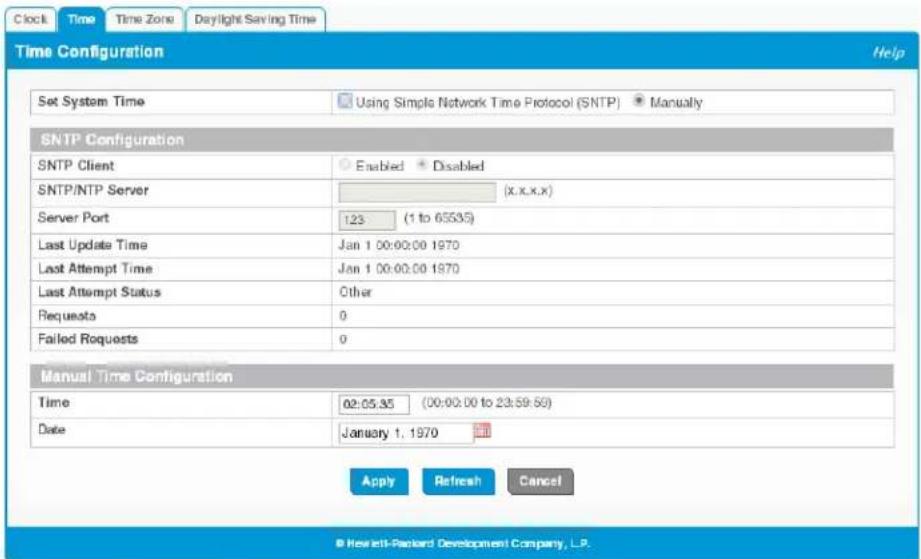
Setup Network
System Time Pages
Table 3-3. Time Configuration Fields
| Field Description | |
| Set System Time | Select Using Simple Network Time Protocol (SNTP) to configure the switch to acquire its time settings from an SNTP server. When selected, only the SNTP Configuration fields are available for configuration.Select Manually to disable SNTP and configure the time manually. When selected, only the Manual Time Configuration fields are available for configuration. |
| SNTP Configuration | |
| SNTP Client | Select Enabled or Disabled (default) to configure the SNTP client mode. When disabled, the system time increments from 00:00:00, 1 Jan 1970, which is set at bootup. |
| SNTP/NTP Server Specify the IPv4 address of the SNTP server to send requests to. | |
| Server Port | Specify the server's UDP port to listen for responses/broadcasts. The range is 1 to 65535 and the default is 123. |
| Last Update Time The date and time (UTC) of the last update from this server. | |
| Last Attempt Time | The data and time (UTC) that the switch last attempted to obtain the time from this server. |
| Last Update Status | The status of the last update request to the SNTP server, which can be one of the following values:Other—None of the following values apply or no message has been received.Success—The SNTP operation was successful and the system time was updated.Request Timed Out—A SNTP request timed out without receiving a response from the SNTP server.Bad Date Encoded—The time provided by the SNTP server is not valid.Version Not Supported—The SNTP protocol version supported by the server is not compatible with the version supported by the switch client.Server Unsynchronized—The SNTP server is not synchronized with its peers. This is indicated via the leap indicator field in the SNTP message.Blocked—The SNTP server indicated that no further requests were to be sent to this server. This is indicated by a stratum field equal to 0 in a message received from the server. |
| Requests | The number of requests made to the SNTP sever since the switch was rebooted. |
| Failed Requests | The number of failed SNTP requests made to this server since last reboot. |
| Manual Time Configuration | |
| Time | Specify the current time in HH:MM:SS format. |
| Date | Click the date field to display a calendar and select the current date. |
Click Apply to save any changes for the current boot session. The changes take effect immediately.
Time Zone Configuration
The Time Zone Configuration page is used to configure your local time zone.
To display this page, click Setup Network > System Time in the navigation pane and click the Time Zone tab.
Figure 3-4. Time Zone Configuration Page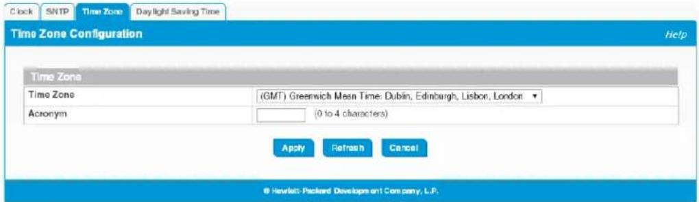
Table 3-4. Time Zone Configuration Fields
| Field Description | |
| Time Zone | Select the time zone for your location. The default is (GMT) Greenwich Mean Time: Dublin, Edinburgh, Lisbon, London. |
| Acronym | Specify an acronym for the time zone. The acronym can have up to four alphanumeric characters and can contain dashes, underscores, and periods. |
Click Apply to save any changes for the current boot session. The changes take effect immediately.
Daylight Saving Time Configuration
The Daylight Saving Time Configuration page is used to configure if and when Daylight Saving Time (DST) occurs within your time zone. When configured, the system time adjusts automatically one hour forward at the start of the DST period, and one hour backward at the end.
To display the Daylight Saving Time page, click Setup Network > System Time in the navigation panel and click the Daylight Saving Time tab.
Figure 3-5. Daylight Saving Time Configuration Page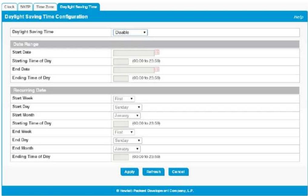
Table 3-5. Daylight Saving Time Configuration Fields
| Field Description | |
| Daylight Saving Time Select how DST will operate:Disable—No clock adjustment will be made for DST. This is the default selection.Recurring—The settings will be in effect for the upcoming period and subsequent years.EU—The system clock uses the standard recurring daylight saving time settings used in countries in the European Union.USA—The system clock uses the standard recurring daylight saving time settings used in the United States.Non-Recurring—The settings will be in effect only for a specified period during the year (that is, they will not carry forward to subsequent years).When a DST mode is enabled, the clock will be adjusted one hour forward at the start of the DST period and one hour backward at the end. | |
| Date Range | Set the following to indicate when the change to DST occurs and when it ends.These fields are editable when Non-Recurring is selected as the DST mode:Start/End Date—Use the calendar to set the day, month, and year when the change to/from DST occurs. Or, enter the hours and minutes in 24-hour format (HH:MM).Starting Time of Day—Set the hour and minutes when the change to/from DST occurs. |
| Recurring Date | When Recurring is selected as the DST mode, the following fields display:Start/End Week—Set the week of the month, from 1 to 5, when the change to/from DST occurs. The default is 1 (the first week of the month).Start/End Day—Set the day of the week when the change to/from DST occurs.Start/End Month—Set the month when the change to/from DST occurs.Starting/Ending Time of Day—Set the hour and minutes when the change to/from DST occurs. |
Click Apply to save any changes for the current boot session. The changes take effect immediately.
Switching Features
You can use the Switching pages to configure port operation and capabilities.
Port Configuration
You can use the Port Configuration pages to display port status, configure port settings, and view statistics on packets transmitted on the port.
Port Status
The Port Status page displays the operational and administrative status of each port and enables port configuration. To view this page, click Switching > Port Configuration in the navigation pane.
Figure 4-1. Port Status Page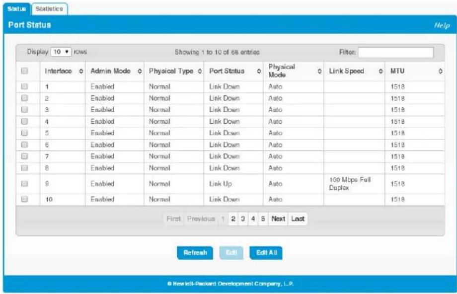
Table 4-1. Port Status Fields
| Field Description | |
| Interface The port or trunk ID. | |
| Admin Mode | Displays whether the interface is administratively enabled or disabled. All ports are enabled by default. |
| Physical Type | The interface type, which can be one of the following:Normal—The port is a normal port, which means it is not a LAG member or configured for port mirroring. All ports are normal ports by default.Trunk Member—The port is a member of a trunk.Mirrored—The port is configured to mirror its traffic (ingress, egress, or both) to another port (the probe port).Probe—The port is configured to receive mirrored traffic from one or more source ports. |
| Port Status | The physical status (Link Up or Link Down) of the link at the port. |
| Physical Mode | Displays whether Auto negotiation is enabled or disabled on the port.If the mode is Auto, the port's maximum capability are advertised, and the duplex mode and speed are set from the auto-negotiation process. The physical mode for a trunk is “Trunk”. |
| Link Speed | The physical speed at which the port is operating. If no link is present, this field is empty. |
| MTU | The Maximum Transmission Unit (MTU) specifies the largest frame size that can be transmitted on the port. The default is 1518 bytes. |
Modifying Interface Settings
To change the Admin Mode or Physical Mode of one or more interfaces, and to add a brief interface description, select the interfaces and click Edit. Or, click Edit All to modify all interfaces.
Figure 4-2. Edit Port Configuration Page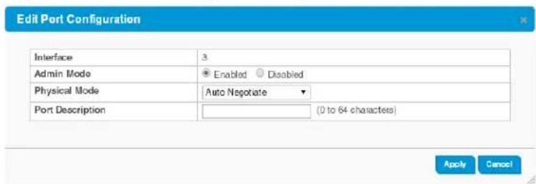
Table 4-2. Edit Port Configuration Fields
| Field Description | |
| Interface The interface or interfaces to be configured. | |
| Admin Mode | Select Enabled to make the port accessible on the network, or Disabled to prevent the port from receiving or forwarding packets. |
| Physical Mode | Select the duplex mode and transmission rate for the selected interface. The options may differ depending on the port type and include options up to the port's maximum capability.When Auto Negotiate (the default) is selected, the port negotiates an appropriate link speed with its link partner. |
| Port Description | Add an description of the interface (optional). |
Click Apply to save any changes for the current boot session. The changes take effect immediately and are applied to each of the selected interfaces.
Port Summary Statistics
The Port Summary Statistics page displays statistics on packets transmitted and received on each port or trunk. These statistics can be used to identify potential problems with the switch. The displayed values are the accumulated totals since the last clear operation.
To display the Port Summary Statistics page, click Switching > Port Configuration in the navigation pane and select the Statistics tab.
Figure 4-3. Port Summary Statistics Page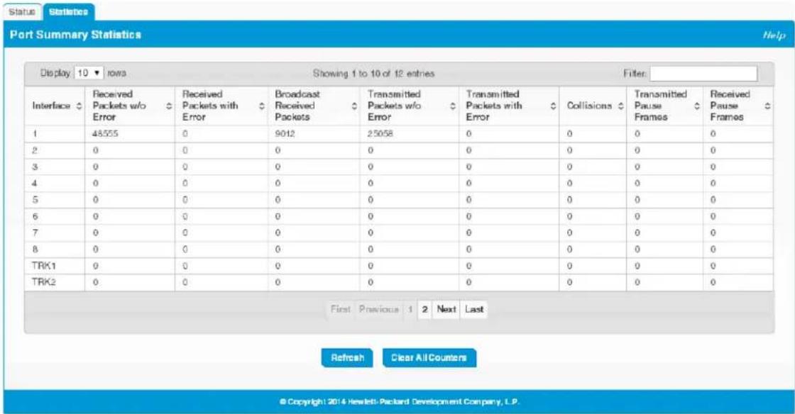
Table 4-3. Port Summary Fields
| Field Description | |
| Interface The port or trunk ID. | |
| Received Packets w/o Error | The count of packets received on the port with out any packet errors. |
| Received Packets with Error | The count of packets received on the port with errors. |
| Broadcast Received Packets | The count of Broadcast packets received on the port. |
| Transmitted Packets w/o Error | The number of packets transmitted out of that port with out any packet errors. |
| Transmitted Packets with Error | The number of packets transmitted out of the port with packet errors. |
| Collisions The number of packet collisions. | |
| Transmitted Pause Frames | The number of Ethernet pause frames transmitted. (This information is collected for ports but not for trunks.) |
| Received Pause Frames | The number of Ethernet pause frames received. (This information is collected for ports but not for trunks.) |
Click Clear All Counters to reset all statistics to zero.
Port Mirroring
Port mirroring is used to monitor the network traffic that one or more ports send and receive. The Port Mirroring feature creates a copy of the traffic that the source interface handles and sends it to a destination port. All traffic from the source can be mirrored and sent toward the destination port. When the destination is a port on the local device, a network protocol analyzer is typically connected to the port. Multiple switch ports can be configured as source ports, with each port mirrored to the same destination.
Caution
■ When configuring port mirroring, avoid oversubscribing the destination port to prevent the loss of mirrored data. ■ While a port is used as the destination port for mirrored data, the port cannot be used for any other purpose; the port will not receive and forward traffic.
To display the Port Mirroring page, click Switching > Port Mirroring in the navigation pane.
Figure 4-4. Port Mirroring Page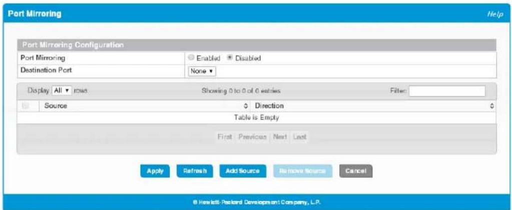
Table 4-4. Port Mirroring Fields
| Field Description | |
| Port Mirroring | Enables or disables port mirroring globally on the switch. This feature is disabled by default. |
| Destination Port | Select the switch port to which packets will be mirrored. Typically, a network protocol analyzer is connected to this port. |
If you change these settings, click Apply to save any changes for the current boot session. The changes take effect immediately.
The Port Mirroring page also displays summary information for all source ports configured for mirroring. To add one or more source ports to mirror to the destination port, click Add Source.
Figure 4-5. Add Port Mirroring Source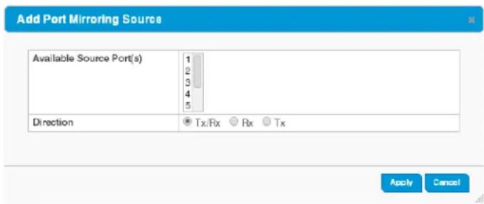
Table 4-5. Add Port Mirroring Source Fields
| Field Description | |
| Available Source Port(s) | Select the source ports or trunks to mirror to the destination port. To select multiple source ports, hold downCtrlwhile selecting ports. You can also select the CPU to mirror traffic sent from the switch CPU to the switch interfaces or vice versa.Ports that are included as part of a trunk cannot be selected individually as source ports, but trunks can be selected as source ports.The port selected as the Destination Port is greyed-out and unavailable for selection. |
| Direction Select the type of traffic to mirror to the port:• Tx/Rx— All packets transmitted and received on the source port are mirrored.• Rx— Only packets received on the source port are mirrored.• Tx— Only packets transmitted on the source port are mirrored.If the CPU is selected as the source port, selectRxto monitor traffic received by any switch interface from the switch CPU, and selectTxto monitor traffic sent from any switch interface to the switch CPU. | |
Click Apply to save any changes for the current boot session. The changes take effect immediately.
Jumbo Frames
Use the Jumbo Frames page to enable the switch to forward jumbo Ethernet frames. The jumbo frames feature extends the standard Ethernet Maximum Transmission Unit (MTU) from 1518 bytes (1522 bytes with a VLAN header) to 9216 bytes. If it is enabled, any device connecting to the same broadcast domain should also support jumbo frames.
To display the Jumbo Frames page, click Switching > Jumbo Frames in the navigation pane.
Figure 4-6. Jumbo Frames Page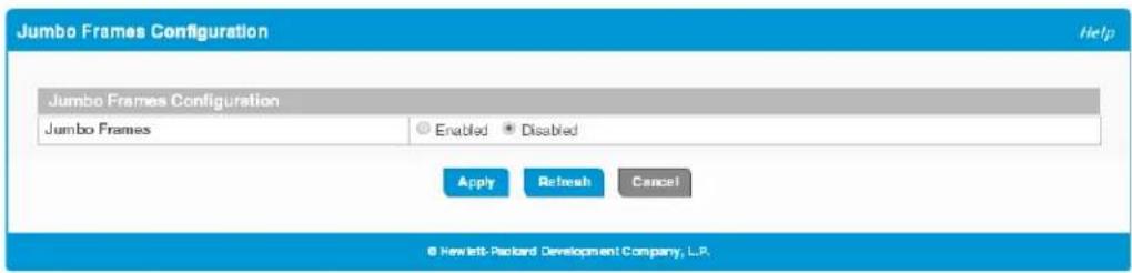
Select Enabled to configure the switch to forward jumbo frames up to 9216 bytes. If you change this setting, click Apply to save the new value. The change takes effect immediately. This feature is disabled by default.
Flow Control
When a port becomes congested, it may begin dropping all traffic for small bursts of time during the congestion condition. This can lead to high-priority and/or network control traffic loss. When 802.3x flow control is enabled, a lower-speed switch can communicate with a higher-speed switch by requesting that the higher-speed switch refrain from sending packets. Transmissions are temporarily halted to prevent buffer overflows.
Note: Flow control works well when the Link Speed is auto-negotiated.
Use the Flow Control page to enable or disable this functionality. It is disabled by default and can be enabled globally on all switch ports.
To display the Flow Control page, click Switching > Flow Control in the navigation pane.
Figure 4-7. Flow Control Page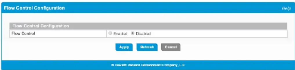
Select Enabled to use flow control on the switch. If you change this setting, click Apply to save the change. The change takes effect immediately.
Spanning Tree
Spanning Tree Protocol (STP) is a Layer 2 protocol that provides a tree topology for switches on a bridged LAN. STP allows a network to have redundant paths without the risk of network loops. STP uses the spanning-tree algorithm to provide a single path between end stations on a network. When STP is enabled, bridges on a network exchange bridge protocol data units (BPDUs) to communicate changes in the network topology and to provide information that helps determine the optimal paths between network segments.
HP 1820 series switches support STP versions IEEE 802.1D (STP), and 802.1w (Rapid STP, or RSTP). RSTP reduces the convergence time for network topology changes to about 3 to 5 seconds from the 30 seconds or more for the IEEE 802.1D STP standard. RSTP is intended as a complete replacement for STP, but can still interoperate with switches running the STP protocol by automatically reconfiguring ports to STP-compliant mode if they detect STP protocol messages from attached devices.
Global STP Settings and Port Status
To display the Spanning Tree Configuration page, click Switching > Spanning Tree in the navigation pane. This page includes global STP settings and interface status information.
Figure 4-8. Spanning Tree Configuration Page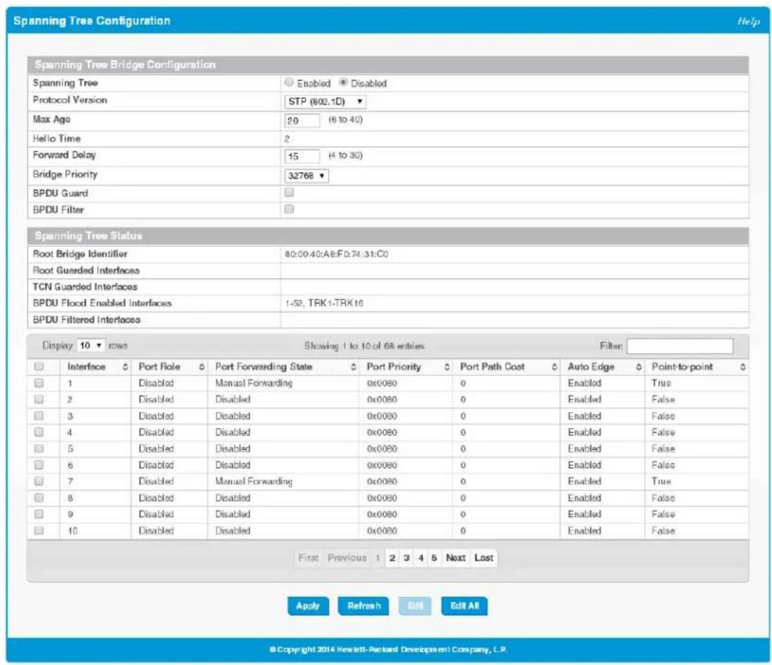
The following fields configure global STP settings:
Table 4-6. Spanning Tree Bridge Configuration Fields
| Field Description | |
| Spanning Tree Bridge Configuration | |
| Spanning Tree | Click Enabled to enable the Spanning Tree protocol mode on all ports. This feature is disabled on all ports by default. |
| Protocol Version Select the protocol version to use:• STP (802.1D). This is the default selection.• RSTP (802.1w) | |
| Max Age | The maximum number of seconds after which BPDU information is considered to be aged out or invalid. An expired Max Age parameter is typically the result of a link failure.This value must be less than or equal to 2 x (bridge forward delay - 1) and greater than or equal to 2 x (bridge hello time + 1).The range is from 6 to 40 seconds and the default is 20 seconds. |
Switching Features
Spanning Tree
| Field Description | |
| Hello Time | The interval between periodic transmissions of STP BPDUs by designated ports. This value is set to 2 seconds and cannot be changed. |
| Forward Delay | The amount of time a bridge remains in a listening and learning state before forwarding packets. The range is from 4 to 30 seconds and the default is 15 seconds. |
| Bridge Priority | A value that helps determine which bridge in the spanning tree is elected as the root bridge during STP convergence. A lower value increases the probability that the bridge becomes the root bridge. the default value is 32768. |
| BPDU Guard | When enabled globally, the switch can disable edge ports that receive BPDU packets. This prevents a new device from entering the existing STP topology. Thus, devices that were originally not a part of STP are not allowed to influence the STP topology. When disabled, an edge port that receives a BDPU becomes a non-edge port, which can affect the STP topology.When enabling BPDU Guard, also ensure that the desired interfaces are operating as edge ports by enabling the Admin Edge Port mode for each of those interfaces.This feature is disabled by default. |
| BPDU Filter | When enabled, this feature filters the BPDU traffic on edge ports. When spanning tree is disabled on a port, BPDU filtering allows BPDU packets received on that port to be dropped.When enabling BPDU Filter, also ensure that the desired interfaces are operating as edge ports by enabling the Admin Edge Port mode for each of those interfaces.This feature is disabled by default. |
| Spanning Tree Interface Status—The following fields list the interfaces on which the feature is enabled. See Table 4-7 on page 4-14 for descriptions of these features. | |
| Root Bridge Identificr | The bridge ID of the root bridge for the spanning tree. The identifier is made up of the bridge priority and the base MAC address. When electing the root bridge for the spanning tree, if the bridge priorities for multiple bridges are equal, the bridge with the lowest MAC address is elected as the root bridge. |
| Root Guarded Interfaces | A list of the interfaces for which Root Guard is enabled. |
| TCN Guarded Interfaces | A list of the interfaces for which TCN Guard is enabled. |
| BPDU Flood Enabled Interfaces | A list of the interfaces for which the BPDU Flood feature is enabled. |
| BPDU Filtered Interfaces | A list of the interfaces for which BPDU Filter is enabled. |
| Spanning Tree Interface Settings—This page also displays a table with configured settings for each interface. See Table 4-7 on page 4-14 for descriptions of these settings. This table displays the following additional field. | |
| Port Role | The role of the port with respect to spanning tree functionality, which is one of the following:Root:A port on the non-root bridge that has the least-cost path to the root bridge.Designated:A port that has the least-cost path to the root bridge on its segment.Alternate:A blocked port that has an alternate path to the root bridge.Backup:A blocked port that has a redundant path to the same network segment as another port on the bridge.Disabled:The port is administratively disabled and is not part of the spanning tree. |
| Port Forwarding State | Ports can be in one of the following STP states, depending on its configuration and the status of the STP topology convergence:Blocking—The port discards user traffic and receives, but does not send, BPDUs. During the election process, all ports are in the blocking state. The port is blocked to prevent network loops.Listening—The port sends and receives BPDUs and evaluates information to provide a loop-free topology. This state occurs during network convergence and is the first state in transitioning to the forwarding state.Learning—The port learns the MAC addresses of frames it receives and begins to populate the MAC address table. This state occurs during network convergence and is the second state in transitioning to the forwarding state.Forwarding—The port sends and receives user traffic.Disabled—The port is administratively disabled and is not part of the spanning tree. This is the default selection. |
If you modify any global settings, click Apply to save the changes for the current boot session. The changes take effect immediately.
Port STP Settings
To configure these settings on one or more interfaces, select the interfaces on the Spanning Tree Configuration page and click Edit.
Figure 4-9. Edit Spanning Tree Port Configuration Page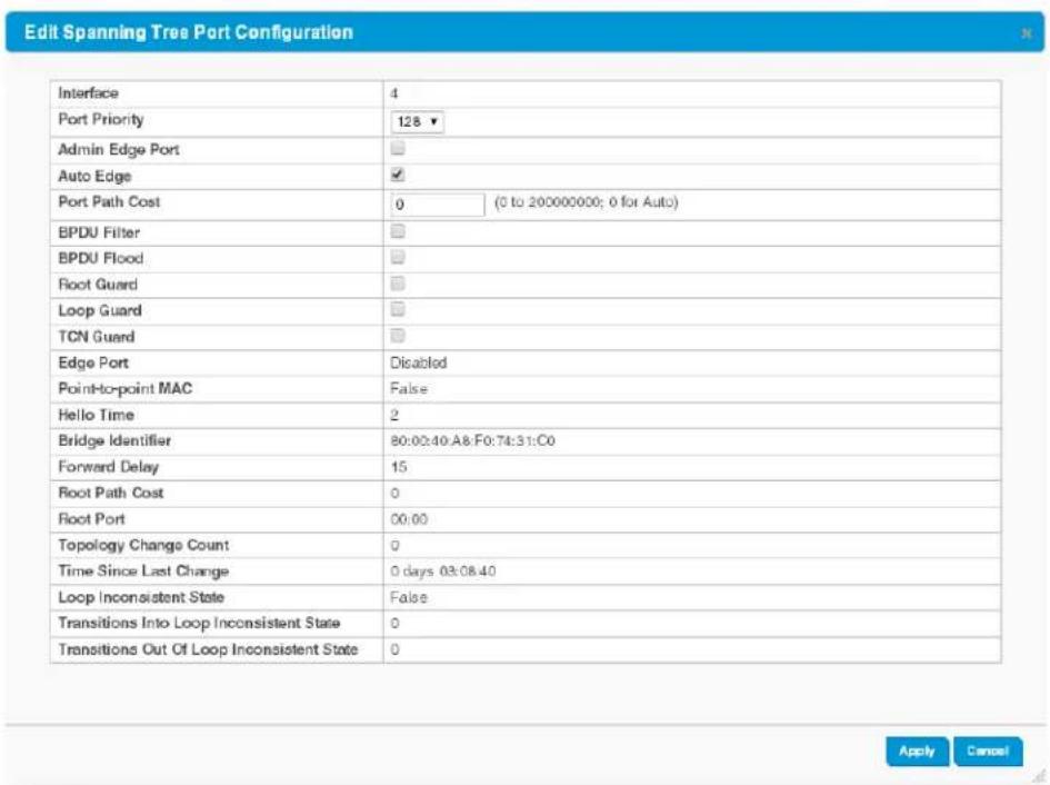
The Edit Spanning Tree Port Configuration page enables you to configure settings and view status and statistics for the selected interfaces.
Table 4-7. Edit Spanning Tree Port Configuration Fields
| Field Description | |
| Configurable Port Settings | |
| Interface The port and trunk IDs selected for configuration. | |
| Port Priority | The priority for the port within Spanning Tree. This value is used in determining which port on a switch becomes the root port when two ports have the same least-cost path to the root. The higher priority port (that is, the port with the lower priority value) becomes the root port. If the priority values are the same, the port with the lower interface index becomes the root port.Select a value from 0 to 240 in increments of 16. The default is 128. |
| Admin Edge Port | Select this option to administratively configure the port as an edge port (that is, a port that connects directly to a network host or network segment that has no other bridge). During STP convergence, edge ports automatically are placed in the forwarding state and are not included in the spanning tree topology. This feature is disabled by default. |
| Auto Edge | When selected, the switch automatically designates the port as an edge port if it does not receive any BPDUs within a specified time period. This feature is enabled by default. |
| Port Path Cost | Specify the path cost, which is used when establishing the active topology of the network. Lower path cost ports are chosen as forwarding ports in favor of higher path cost ports. Specify Auto or assign a value from 1 to 200000000, or specify 0 for Auto mode. When set to 0, the path cost is set using the 802.1D recommended values. |
| BPDU Filter | When enabled, this feature filters the BPDU traffic on the edge ports. When spanning tree is disabled on a port, BPDU filtering allows BPDU packets received on that port to be dropped.When enabling BPDU Filter, also ensure that the desired interfaces are operating as edge ports by enabling the Admin Edge Port mode for each of those interfaces.This feature is disabled by default. |
| BPDU Flood | When enabled on a port, if the port receives a BPDU packet and STP is disabled on the port, the BPDU is flooded to all switch ports that are also disabled for spanning tree. This feature is enabled by default. |
| Root Guard | When enabled on a port, that port cannot be selected as the root port even if it receives superior STP BPDUs. The port is assigned an “alternate” port role and enters a blocking state if it receives superior STP BPDUs. Select this option to enable root guard for the port. This feature is disabled by default. |
| Loop Guard | When enabled on a port, this setting prevents the port from erroneously transitioning from the blocking to the forwarding state when it stops receiving BPDUs. The port is marked as being in the loop-inconsistent state. In this state, the interface does not forward frames. This feature is disabled by default. |
| TCN Guard | When enabled on a port, the port does not propagate received topology change notifications and topology changes to other ports. This feature is disabled by default. |
| Port Status and Statistics | |
| Edge Port | Indicates whether the port is currently operating as an Edge port, either due to administrative configuration or to automatic configuration by the Auto Edge feature. |
| Point-to-point MAC | Indicates whether the port connects to a single device (True) or to a shared medium with multiple devices (False). A point-to-point link has only one device at the far end. |
| Hello Time | The amount of time the port waits between sending “hello” BPDUs. |
| Bridge Identifier | A unique value that identifies the bridge. It is automatically generated based on the bridge priority value and the basic MAC address of the bridge. |
| Forward Delay | The amount of time in seconds a bridge remains in the listening and learning state during STP convergence, before moving to the forwarding state. |
Switching Features Spanning Tree
| Field Description | |
| Root Path Cost | The path cost to the designated root bridge. Traffic from a connected device to the root bridge takes the least-cost path to the bridge. If the value is 0, the cost is automatically calculated based on port speed. |
| Root Port | The port on the switch with the least-cost path to the designated root bridge in the spanning tree topology. |
| Topology Change Count | The number of times the topology of the spanning tree has changed. |
| Time Since Last Change | The time that has passed since the last spanning tree topology change. This value is reset to zero when the switch is reset. |
| Loop Inconsistent State | Identifies whether the interface is currently in a loop-inconsistent state. An interface transitions to a loop-inconsistent state if loop guard is enabled and the port stops receiving BPDUs. In this state, the interface does not transmit frames. |
| Transitions Into Loop Inconsistent State | The number of times the port has transitioned into loop inconsistent state. |
| Transitions Out Of Loop Inconsistent State | The number of times this interface has transitioned out of loop-inconsistent state. |
If you modify these settings, click Apply to save the changes for the current boot session. The changes take effect immediately.
Loop Protection
Loops on a network consume resources and can degrade network performance. Detecting loops manually can be very cumbersome and time consuming. The HP 1820 series switch software provides an automatic loop protection feature.
When loop protection is enabled on the switch and on one or more interfaces (ports or trunks), the interfaces send loop protection protocol data units (PDUs) to the multicast destination address 09:00:09:09:13:A6. When an interface receives a loop protection PDU, it compares the source MAC address with its own. If the MAC addresses match, a loop is detected and a configured action is taken, which may include shutting down the port for a specified period.
An interface can be configured to receive and take action in response to loop protection PDUs, but not to send out the PDUs itself.
Ports on which loop protection is disabled drop the loop protection packets silently.
Loop Protection Status
Use the Loop Protection Status page to display the status of this feature on each port. To display this page, click Switching > Loop Protection in the navigation pane.
Figure 4-10. Loop Protection Status Page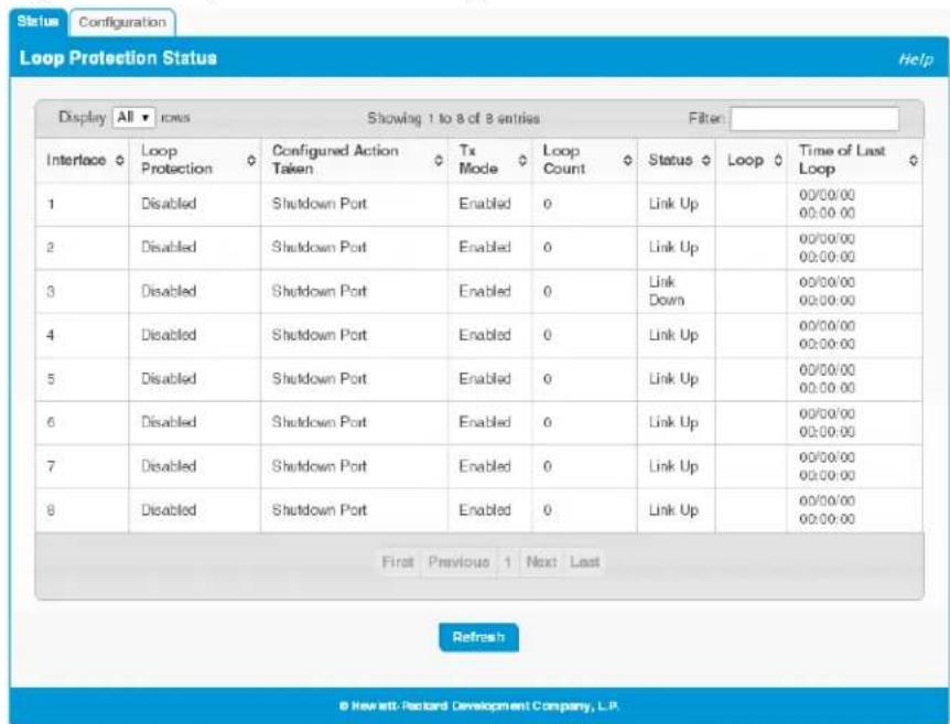
Table 4-8. Loop Protection Status Fields
| Field Description | |
| Interface The port or trunk ID. | |
| Loop Protection | Indicates whether the feature is administratively enabled or disabled on the port. |
| Configured Action Taken | The action that is set to occur when a loop is detected on the port with loop protection enabled:Shutdown Port—The port will be shut down for the configured period.Shutdown Port and Log—The event will be logged and the port it shut down for the configured period.Log Only—The event will be logged and the port remains operational. |
| Tx Mode | Indicates whether the interface is configured (Enabled) to send out loop protection protocol data units (PDUs) to actively detect loops. When Disabled, the interface does not send out loop protection PDUs but can receive them from other ports. |
| Loop Count | The number of loops detected on this interface since the last system boot or since statistics were cleared. |
| Status | The current loop protection status of the port.Link Upindicates the interface is operating normally.Link Downindicates that the port has been shut down due to the detection of a loop. |
| Loop Whether a loop is currently detected on the port. | |
| Time of Last Loop The date and time of the last loop event detected. | |
Loop Protection Configuration
Use the Loop Protection Configuration page to configure this feature on one or more interfaces. To display this page, click Switching > Loop Protection in the navigation pane and select the Configuration tab.
Figure 4-11. Loop Protection Configuration Page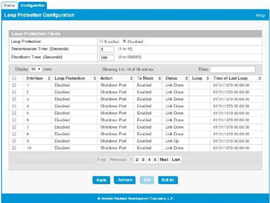
Table 4-9. Loop Protection Configuration Global Fields
| Field Description | |
| Loop Protection | Select Enabled or Disabled to administratively enable or disable this feature globally on the switch. This feature is disabled by default. |
| Transmission Time | The interval at which the switch sends loop protection PDUs on interfaces that are enabled to send them. The range is 1 to 10 seconds and the default is 5 seconds. |
| Shutdown Time | The period that a port is shut down when a loop is detected. This setting applies only to ports that are configured to be shut down upon the detection of a loop. The range is 0 to 604800 seconds and the default is 180 seconds. |
If you modify these settings, click Apply to update the switch configuration. Your changes take effect immediately.
Configuring Loop Protection Settings on Interfaces
To configure loop protection settings on one or more interfaces, select the interfaces and click Edit. Or, select Edit All to configure all interfaces.
Figure 4-12. Edit Loop Protection Port Configuration Page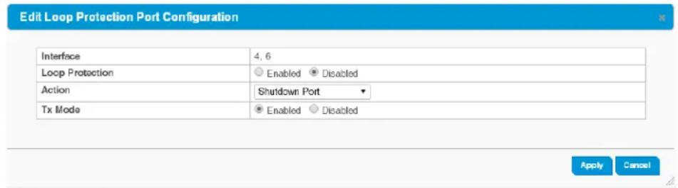
Switching Features
Loop Protection
Table 4-10. Loop Protection Configuration Global Fields
| Field Description | |
| Interface The port or ports that are being configured. | |
| Loop Protection | SelectEnabledorDisabledto administratively enable or disable this feature on the selected interfaces. By default, this feature is disabled on all interfaces.Note that loop protection can be enabledon static trunks, but cannot be enabled on trunks that are dynamically formed through LACP. |
| Action | Select the action to occur when a loop is detected on a port with loop protection enabled:Shutdown Port—The port will be shut down for the configured period. This is the default selection.Shutdown Port and Log—The event will be logged and the port it shut down for the configured period.Log Only—The event will be logged and the port remains operational. |
| Tx Mode | When set toEnabled(the default), the port actively sends out loop protection PDUs to other ports on which the loop protection feature is enabled. When set toDisabled, the port does not send loop protection PDUs but can receive them from other ports. Tx Mode is enabled by default. |
Click Apply to update the switch configuration. Your changes take effect immediately.
IGMP Snooping
Internet Group Management Protocol (IGMP) snooping allows a device to forward multicast traffic intelligently. Multicast IP traffic is traffic that is destined to a host group. Host groups are identified by class D IP addresses, which range from 224.0.0.0 to 239.255.255.255. Based on the IGMP query and report messages, the switch forwards traffic only to the ports that request the multicast traffic. This prevents the switch from broadcasting the traffic to all ports, which could affect network performance.
When enabled, the switch supports IGMPv1 and IGMPv2.
To enable IGMP snooping and view global status information, click Switching > IGMP Snooping in the navigation pane.
Figure 4-13. IGMP Snooping Page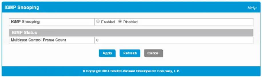
Table 4-11. IGMP Snooping Fields
| Field Description | |
| IGMP Snooping | Select Enabled to globally enable IGMP snooping on the switch. This feature is disabled by default. |
| MulticastControl Frame Count | The number of multicast control frames that have been processed by the CPU since the switch was last reset. |
If you change the Admin Mode, click Apply to save the changes for the current boot session. The changes take effect immediately.
Virtual LAN
On a Layer 2 switch, Virtual LAN (VLAN) support offers some of the benefits of both bridging and routing. Like a bridge, a VLAN switch forwards traffic based on the Layer 2 header, which is fast, and like a router, it partitions the network into logical segments, which provides better administration, security, and management of multicast traffic.
A VLAN is a set of end stations and the switch ports that connect them. Many reasons exist for the logical division, such as department or project membership. The only physical requirement is that the end station and the port to which it is connected both belong to the same VLAN.
Each VLAN in a network has an associated VLAN ID, which displays in the IEEE 802.1Q tag in the Layer 2 header of packets transmitted on a VLAN. An end station may omit the tag, or the VLAN portion of the tag, in which case the first switch port to receive the packet may either reject it or insert a tag using its default VLAN ID. A given port may handle traffic for more than one VLAN, but it can only support one default VLAN ID.
HP 1820 series switches support up to 64 VLANs.
Viewing VLAN Status and Adding VLANs
Use the VLAN Status page to view information on VLANs currently defined on the switch and to add and edit VLAN information.
To display the VLAN Status page, click VLAN > Configuration in the navigation pane.
Figure 5-1. VLAN Status Page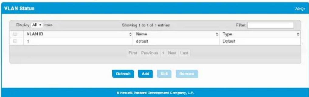
By default, VLAN 1 is defined on the switch. It is designated as the default VLAN and cannot be modified or deleted. All ports are members of VLAN 1 by default.
VLAN 1 is also the default management VLAN, which identifies the VLAN that management users must be a member of. The administrator can configure a different VLAN as the management VLAN. See Table 3-1 on page 3-2 for additional information about the management VLAN.
The following information displays for each VLAN:
Table 5-1. VLAN Status Fields
| Field Description | |
| VLAN ID | The numerical VLAN identifier (VID) assigned to the VLAN, from 1 to 4093.Note: VLAN 0 (VID = 0x000 in a frame) is reserved and is used to indicate that the frame does not belong to any VLAN. In this case, the 802.1Q tag specifies only a priority and the value is referred to as a priority tag. |
| Name A user-configurable name that identifies the VLAN. | |
| Type The type of VLAN, which can be one of the following:Default—The default VLAN. This VLAN is always present, and the VLAN ID is 1.Static—A user-configured VLAN. | |
Adding VLANs
To add a VLAN, click Add. In the VLAN ID or Range field, specify one or more VLAN IDs in the range 2 to 4093, and click Apply.
To create a range of VLANs, specify the beginning and ending VLAN IDs, separated by a hyphen. To create multiple non-sequential VLANs, separate each VLAN ID with a comma.
You can create up to 64 VLANs.
Changing a VLAN Name
When you create a VLAN, a default name is automatically assigned in the form VLANnnnn, where nnnn is the VLAN number with preceding zeroes as needed. To change the VLAN name, select it on the VLAN Status page and click Edit. On the Edit VLAN Configuration page, specify the new name consisting of 0 to 32 alphanumeric characters and click Apply.
Configuring Interfaces as VLAN Members
By default, all ports and trunks are assigned membership in the default VLAN (VLAN 1). If you create additional VLANs, you can add interfaces as members of the new VLANs and configure VLAN tagging settings for the interfaces. You can also modify interface memberships in VLAN 1.
To configure interface VLAN memberships, click VLAN > Port Membership in the navigation pane.
Figure 5-2. VLAN Port Membership Page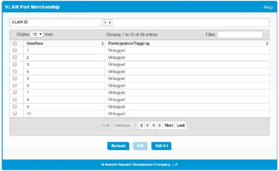
Table 5-2. VLAN Port Membership Fields
| Field Description | |
| VLAN ID | Select the VLAN ID for which you want to view interface memberships. |
| Interface The port or trunk ID. | |
| Participation/Tagging | The current membership mode and tagging behavior for each port in this VLAN, which is one of the following:Exclude—The port is not configured to be a member of the selected VLAN.Tagged—The port is a tagged member of the selected VLAN. When frames in this VLAN are forwarded on this port, the VLAN ID will be included in the frame’s Ethernet header.Untagged—The port is an untagged member of the selected VLAN. When frames in this VLAN are forwarded on this port, the VLAN ID will not be included in the frame’s Ethernet header. |
To configure port membership to the selected VLAN, select one or more ports and click Edit. Or, click Edit All to configure all ports at the same time.
On the Edit VLAN Port Membership page, configure the Participation/Tagging setting to specify whether the ports are excluded from the VLAN or are included as a tagged or untagged member. Consider the following guidelines when editing VLAN port memberships and settings:
Note
A port can be an untagged member of only one VLAN. If you change the VLAN that a port is an untagged member of, then the port will be excluded from the VLAN where it was previously an untagged member. A port can be a tagged member of multiple VLANs. All ports must be a member of at least one VLAN, as either a tagged or an untagged member. You cannot exclude a port from a VLAN unless the port is a member of at least one other VLAN. If you exclude a port from the management VLAN, a computer connected to the switch via that port will be unable to access the switch management interface. Ports belonging to a trunk cannot be assigned membership in a VLAN, although the trunk itself can be a member of one or more VLANs. When a member port is added to a trunk, it loses any previous VLAN memberships and acquires those of the trunk. When deleted from a trunk, a port loses the VLAN memberships of the trunk and acquires untagged membership in VLAN 1.
Click Apply to save any changes for the currently selected VLAN. The changes take effect immediately.
VLAN Port Configuration
Use the VLAN Port Configuration page to view the port VLAN IDs (PVIDs) and priority values assigned to each VLAN.
To view this page, click VLANs > VLAN Port Configuration in the navigation pane.
Figure 5-3. VLAN Port Configuration Page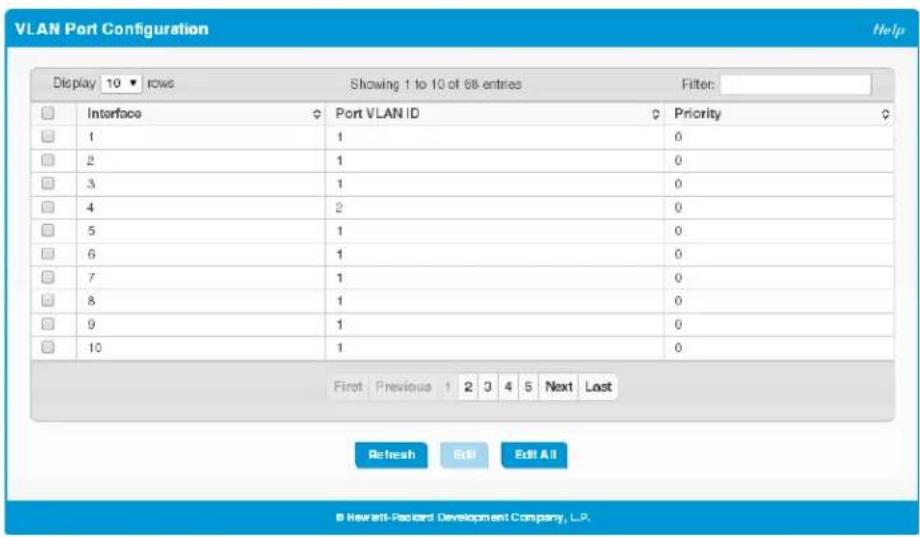
Table 5-3. VLAN Port Configuration Fields
| Field Description | |
| Interface | Select the port on which to configure the VLAN settings. |
| Port VLAN ID | The VLAN ID that this port will assign to untagged or priority-tagged frames received on this port. This value is also known as the Port VLAN ID (PVID). The PVID is set to the ID of the VLAN of which the port is an untagged member. The PVID is not configurable.In a tagged frame, the VLAN is identified by the VLAN ID in the tag.By default, the PVID is 1 for all ports, which is the VLAN ID of the default VLAN, VLAN 1. |
| Port Priority | The default 802.1p priority assigned to Layer-2 untagged packets arriving at the port. A value of 0 (the default) indicates the lowest priority, commonly used for routine traffic, and 7 indicates the highest priority, often reserved for application such as voice and video. The eight port priorities are internally mapped to four class-of-service (CoS) queues. The queues provide differentiated handling when forwarding traffic within the switch (assuming there is congestion on the switch that requires prioritizing traffic).The port priority value is not assigned to tagged packets, which carry priority information in the VLAN tag, or to IP packets that carry priority information in the Differentiated Services Code Point (DSCP) field.A priority value is forwarded externally only if the port is configured as a tagged port. |
To modify these settings for one or more interfaces, select the interface and click Edit. Or, click Edit All to configure all interfaces at the same time.
Trunks
Trunks allow for the aggregation of multiple full-duplex Ethernet links into a single logical link. Network devices treat the aggregation as if it were a single link, which increases fault tolerance and provides load sharing capability.
The 8-port switches support four trunks, the 24-port switches support eight trunks, and the 48-port switches support 16 trunks. On the 8- and 24-port switches, each trunk can support up to four trunk members, and on the 48-port switches, each trunk can support up to eight members.
Note
Trunks are sometimes referred to as link aggregation groups (LAGs).
Trunk Configuration
You can use the Trunk Configuration page to view and edit trunks. The number of trunks on the system is fixed, and all trunks are disabled by default. You can enable, disable, and edit settings for each trunk. Click Trunk > Trunk Configuration in the navigation pane.
Figure 6-1. Trunk Configuration Page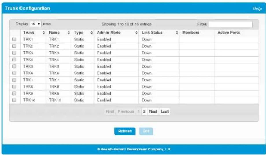
The following information displays for each trunk.
Table 6-1. Trunk Configuration Fields
| Field Description | |
| Trunk The trunk ID. | |
| Name | The configurable trunk name, which is the same as the trunk ID by default. |
| Type | Trunks can be either dynamic or static, but not both:Dynamic—Dynamic trunks use the Link Aggregation Control Protocol (LACP, IEEE standard 802.3ad). An LACP-enabled port automatically detects the presence of other aggregation-capable network devices in the system and exchanges Link Aggregation Control Protocol Data Units (LACPDUs) with links in the trunk. The PDUs contain information about each link and enable the trunk to maintain them.Static—Static trunks are assigned to a bundle by the administrator. Members do not exchange LACPDUs. A static trunk does not require a partner system to be able to aggregate its member ports. This is the default port type.Note that the loop protection feature is not supported on dynamic trunks. If loop protection is enabled on a static trunk and the trunk is changed to a dynamic trunk, loop protection is disabled. |
| Admin Mode | Whether the trunk is administratively enabled or disabled. This feature is enabled by default. |
| Link Status | Indicates the operational status of the trunk interface, which can be Up, Up (SFP) for ports with an installed SFP transceiver, or Down. |
| Members | The ports that are members of the trunk. By default, no ports belong to any trunk. |
| Active Ports | The ports that are actively participating members of a trunk. A member port that is operationally or administratively disabled or does not have a link is not an active port. |
Modifying Trunk Settings
To modify a trunk, select it and click Edit. The Edit Existing Trunk page displays:
Figure 6-2. Edit Existing Trunk Page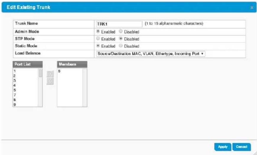
You can define the trunk name, administratively enable and disable the trunk, and select between static and dynamic mode, as described in Table 6-1 on page 6-2. You can also configure the following additional settings:
Table 6-2. Additional Trunk Configuration Fields
| Field Description | |
| STP Mode | The spanning tree protocol (STP) mode of the trunk. When enabled, the trunk participates in the STP operation to help prevent network loops. This feature is enabled on all trunks by default. |
| Load Balance | The hashing algorithm used to distribute traffic load among the physical ports of the trunk while preserving the per-flow packet order. The hashing algorithm uses various packet attributes to determine the outgoing physical port. The following sets of packet attributes can be used to compute the hashing algorithm:Source MAC, VLAN, Ethertype, Incoming PortDestination MAC, VLAN, Ethertype, Incoming PortSource/Destination MAC, VLAN, Ethertype, Incoming PortSource/Destination MAC, VLAN, Ethertype, Incoming Port(this is the default.)Source IP and Source TCP/UDP Port FieldsDestination IP and Destination TCP/UDP Port FieldsSource/Destination IP and TCP/UDP Port Fields |
| Port List/Members | The Port List shows ports that are not members of the trunk, and theMemberslist shows the ports that are members. Use the arrows to move ports between the lists. |
Note the following considerations when configuring trunks and trunk members:
■All ports in a trunk must have the same full-duplex speed.
■ Loop protection is supported on static trunks, but not on dynamic trunks. If loop protection is enabled on a static trunk that is now being changed to a dynamic trunk, loop protection will be disabled on the trunk. A port that is added to a trunk loses its port VLAN membership and is assigned the VLAN memberships configured for the trunk. Individual port VLAN memberships cannot be configured for ports that are members of a trunk. When the port is removed from a trunk, the port is made a member of the default VLAN. ■ When ports are members of a trunk, they take on the STP configuration for the trunk. When ports are removed from a trunk, they take on their earlier configured STP states.
Click Apply to save any changes to the currently selected trunk. The changes take effect immediately.
Trunk Statistics
The Trunk Statistics page displays the flap count for each trunk. A flap occurs when a trunk interface or trunk member port goes down. To display the Trunk page, click Trunks > Statistics in the navigation pane.
Figure 6-3. Trunk Statistics Page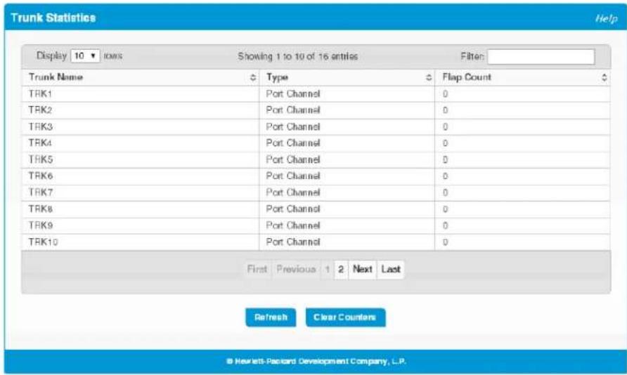
Table 6-3. Trunk Statistics Fields
| Field Description | |
| Trunk Name The user-created name for the trunk. | |
| Type | The interface type, which is either Port-Channel (a trunk) or Member Port (a physical port). |
| Flap Count | The number of times the interface has gone down. The counter for a member port is incremented when the physical port is either manually shut down by the administrator or when its link state is down. When a trunk is administratively shut down, the flap counter for the trunk is incremented, but the flap counters for its member ports are not affected. When all active member ports for a trunk are inactive (either administratively down or link down), then the trunk flap counter is incremented. |
You can click Clear Counters to reset the flap count statistics to 0.
Link Layer Discovery Protocol (LLDP and LLDP-MED)
LLDP is a standardized discovery protocol defined by IEEE 802.1AB. It allows stations residing on a LAN to advertise major capabilities, physical descriptions, and management information to other devices on the network. A network management system (NMS) can access and display this information.
LLDP is a one-way protocol; there are no request/response sequences. Information is advertised in LLDP Protocol Data Units (LLDPDUs) by stations implementing the LLDP transmit function, and LLDPDUs are received and processed by stations implementing the receive function. The transmit and receive functions can be enabled and disabled separately per port. By default, both functions are enabled on all ports.
LLDP-MED is an extension of the LLDP standard. LLDP-MED uses LLDP's organizationally-specific Type-Length-Value (TLV) extensions and defines additional TLVs that make it easier for a VoIP deployment in a wired or wireless LAN/MAN environment. It also makes mandatory a few optional TLVs from LLDP and recommends not transmitting some TLVs.
LLDP Global Configuration
Use the LLDP Global Configuration page to specify global LLDP parameters and to configure the protocol on individual ports.
To display the LLDP Global Configuration page, click LLDP >Configuration in the navigation pane.
Figure 7-1. LLDP Global Configuration Page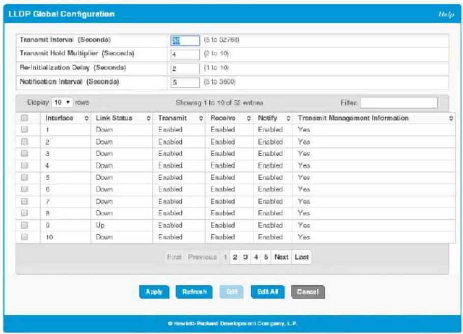
You can configure the following global settings:
Table 7-1. LLDP Global Configuration Fields
| Field Description | |
| Transmit Interval | Specify the time between transmission of LLDPDUs. The range is from 5 to 32768 seconds and the default is 30 seconds. |
| Transmit Hold Multiplier | Specify the multiplier value on the transmit interval, which is used to compute the time-to-live (TTL) value associated with LLDPDUs. The range is from 2 to 10 and the default is 4. |
| Re-Initialization Delay | Specify the number of seconds to wait before attempting to re-initialize LLDP on a port after the LLDP operating mode on the port changes. The range is from 1 to 10 seconds and the default is 2 seconds. |
| Notification Interval | Specify the minimum number of seconds to wait between transmissions of remote data change notifications. The range is from 5 to 3600 seconds and the default is 5 seconds. |
If you change these settings, click Apply to save any changes for the current boot session. The changes take effect immediately.
The following information displays for each interface:
Table 7-2. LLDP Global Configuration—Port Fields
| Field Description | |
| Interface The port or trunk ID. | |
| Link Status | The link status of the interface, which is either Up or Down. An interface that is down does not forward traffic. |
| Transmit | The LLDP advertise (transmit) mode on the interface. If the transmit mode is enabled, the interface sends LLDPDUs that advertise the mandatory TLVs that are enabled. |
Link Layer Discovery Protocol (LLDP and LLDP-MED)
LLDP Global Configuration
| Field Description | |
| Receive | The LLDP receive mode on the interface. If the receive mode is enabled, the device can receive LLDPDUs from other devices. |
| Notify Enable to have LLDP generate a log file entry. | |
| Transmit Management Information | The status of the LLDP remote data change notification on the interface. When enabled, the interface sends notifications when a link partner device is added or removed. |
To modify interface settings, select one or more interfaces and click Edit to display the Edit LLDP Interface page. Or, click Edit All to modify settings on all interfaces.
LLDP Local Device Summary
Use the LLDP Local Device Summary page to view LLDP information for switch interfaces. To display this page, click LLDP > Local Devices in the navigation pane.
Figure 7-2. LLDP Local Device Summary Page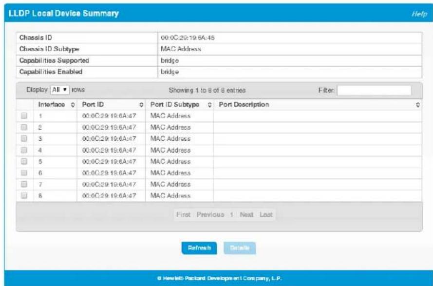
If all LLDP functions are disabled on an interface, then it does not appear in the table.
Table 7-3. LLDP Local Device Summary Fields
| Field Description | |
| Local Device Summary | |
| Chassis ID The hardware platform identifier for the device. | |
| Chassis ID Subtype The type of information used to identify the chassis. | |
| Capabilities Supported | The primary function(s) the device supports. |
| Capabilities Enabled | The primary function(s) the device supports that are enabled. |
| Interface Description | |
| Interface The interface ID. | |
| Port ID | The port identifier, which is the physical address associated with the interface. |
| Port ID Subtype The type of information used to identify the interface | |
| Port Description | A description of the port. An administrator can configure this information on the Port Status page. |
Link Layer Discovery Protocol (LLDP and LLDP-MED)
LLDP Local Device Summary
Displaying Port Details
To view additional LLDP information that the interface advertises, select the interface and click Details.
Figure 7-3. LLDP Local Device Information Page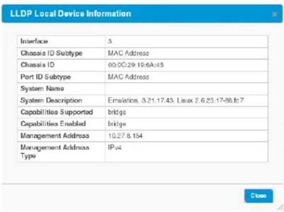
In addition to the fields described in Table 7-3 on page 7-4, this page displays the following fields.
Table 7-4. LLDP Local Device Information Fields
| Field Description | |
| System Name | The user-configured system name for the device. The system name is configured on the Dashboard page. |
| System Description | The device description which includes information about the product model and platform. |
| Management Address | The address, such as an IP address, associated with the management interface of the device. |
| Management Address Type | The protocol type or standard associated with the management address. |
| System IP | The protocol type or standard associated with the management address. |
LLDP Remote Device Summary
Use the LLDP Remote Device Summary page to view information about remote devices for which the switch has received LLDP information. Interfaces that have this option enabled display in this table only if they have received LLDP notifications from a remote device.
To display the Remote Device page, click LLDP > Remote Devices in the navigation pane.
Figure 7-4. LLDP Remote Device Summary Page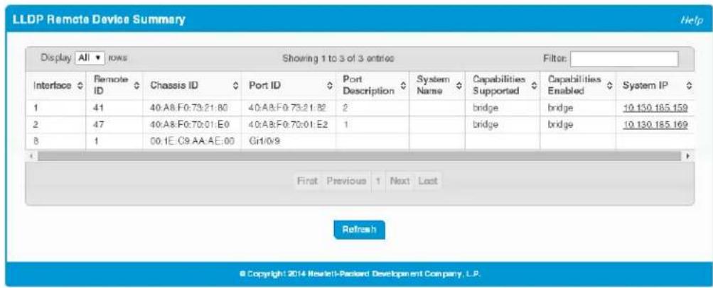
Table 7-5. LLDP Remote Device Summary Fields
| Field Description | |
| Interface | The HP 1820 interface that received the LLDP data from the remote system. |
| Remote ID The identifier assigned to the remote system that sent the LLDPDU. | |
| Chassis ID The hardware platform ID for the remote system. | |
| Port ID | The physical address of the port on the remote device that sent the LLDP data. |
| Port Description | The port description configured on the remote device. If the port description is not configured, the field is blank. |
| System Name | The system description configured on the remote device. If the system description is not configured, the field is blank. |
| Capabilities Supported | The capabilities on the remote device. The possible capabilities include other, repeater, bridge, WLAN AP, router, telephone, DOCSIS cable device, and station. |
| Capabilities Enabled | The capabilities on the remote device that are enabled. |
| System IP | The reported management IP addresses of the remote device. The system IP address provides a link to the web interface on the remote device. |
LLDP Global Statistics
The Link Layer Discovery Protocol (LLDP) Statistics page displays summary and per-port information for LLDP and LLDP-MED frames transmitted and received on the switch.
To display the LLDP Global Statistics page, click LLDP > Statistics in the navigation pane.
Figure 7-5. LLDP Statistics Page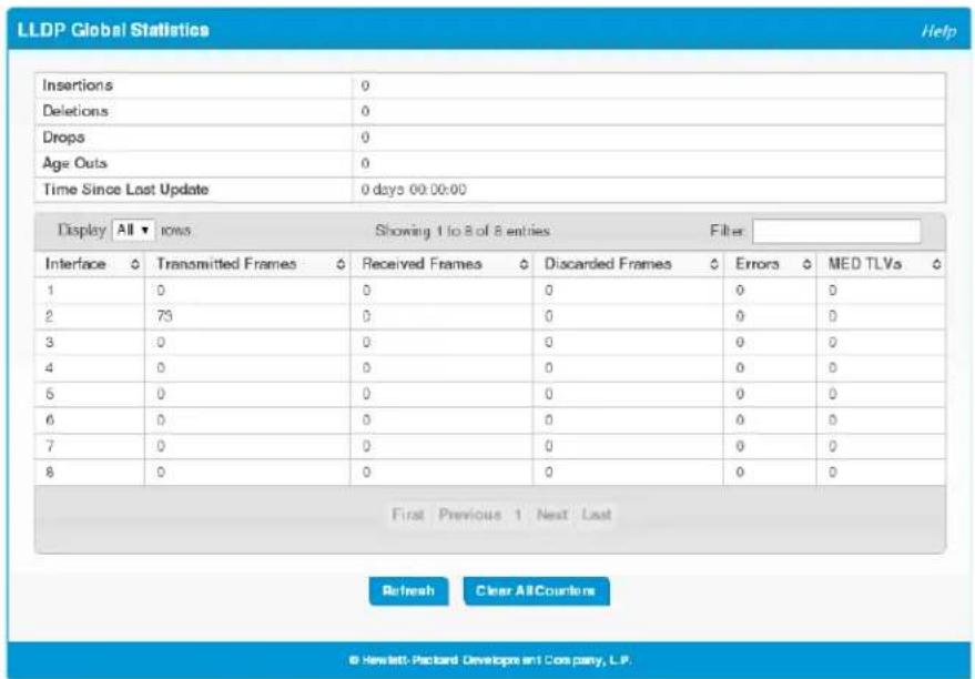
Table 7-6. LLDP Global Statistics Fields
| Field Description | |
| Global Statistics | |
| Insertions | The number of times the complete set of information advertised by a particular MAC Service Access Point (MSAP) has been inserted into tables associated with the remote systems. |
| Deletions | The number of times the complete set of information advertised by a particular MSAP has been deleted from tables associated with the remote systems. |
| Drops | The number of times the complete set of information advertised by a particular MSAP could not be entered into tables associated with the remote systems because of insufficient resources. |
| Age Outs | The number of times the complete set of information advertised by a particular MSAP has been deleted from tables associated with the remote systems because the information timeliness interval has expired. |
| Time Since Last Update | Time when an entry was created, modified, or deleted in the tables associated with the remote system. |
| Interface Statistics | |
| Interface The interface ID. | |
| Transmitted Frames | The number of LLDP frames transmitted on the interface. |
| Received Frames | The number of valid LLDP frames received on the interface. |
| Discarded Frames | The number of LLDP frames the interface discarded for any reason. |
| Errors | The number of invalid LLDP frames received by the LLDP agent on the interface. |
| MED TLVs | The total number of LLDP-MED TLVs received on the interface. |
Click Clear All Counters to reset all statistics to their initial values.
LLDP-MED Global Configuration
LLDP-MED is an enhancement to LLDP that enables:
Auto-discovery of LAN policies (such as VLAN and Layer 2 Priority settings), enabling plug and play networking. Device location discovery for creation of location databases. Extended and automated power management of Power over Ethernet (PoE) endpoints. Inventory management, enabling network administrators to track their network devices and determine their characteristics (manufacturer, software and hardware versions, serial/asset number).
To view and configure global Link Layer Discovery Protocol-Media Endpoint Discovery (LLDP-MED) settings, click LLDP-MED > Configuration in the navigation pane.
Figure 7-6. LLDP-MED Global Configuration Page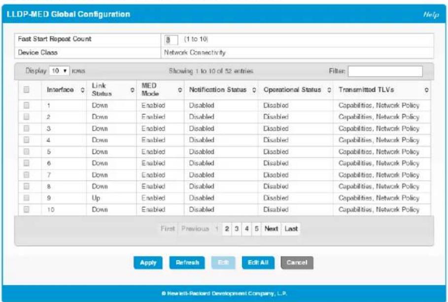
The following global settings display:
Table 7-7. LLDP-MED Global Configuration Fields
| Field Description | |
| Fast Start Repeat Count | The number of LLDP-MED Protocol Data Units (LLDPDUs) that are transmitted during the fast start period when LLDP-MED is enabled. The default is 3. |
| Device Class | The device's MED classification. The HP 1820 is classified as a Network Connectivity device. |
If you change the Fast Start Repeat Count, click Apply to save any changes for the current boot session. The changes take effect immediately.
The following information displays for each port:
Table 7-8. LLDP Global Configuration—Port Fields
| Field Description | |
| Interface The ID of the physical and trunk interfaces. | |
| Link Status | The link status of the interface, which is either Up or Down. An interface that is down does not forward traffic. |
| MED Mode | The administrative status of LLDP-MED on the interface. When enabled, the LLDP-MED transmit and receive functions are effectively enabled on the interface. This feature is enabled by default. |
| Notification Status | Indicates whether LLDP-MED topology change notifications are enabled or disabled on the interface. This feature is disabled by default. |
| Operational Status | Indicates whether the interface is configured to transmit TLVs. To transmit TLVs, the interface must be enabled to receive and transmit LLDPDUs and must be connected to an LLDP-MED device. The switch waits for the LLDP-MED device to advertise its information before the switch transmits its own LLDP-MED TLVs, at which point the operational status becomes enabled. |
| Transmitted TLVs | The LLDP-MED TLV(s) that the interface transmits. The HP 1820, can transmit TLVs of the following types:• Capabilities• Network Policy |
To enable or disable LLDP-MED on one or more interfaces, and to configure related features, select the interfaces and click Edit. Or, click Edit All to modify settings for all ports at the same time.
LLDP-MED Local Device Summary
Use the LLDP-MED Local Device Summary to view the information that is advertised by the switch interfaces when they are enabled for LLDP-MED. To display this page, click LLDP-MED > Local Devices in the navigation pane.
Figure 7-7. LLDP-MED Local Device Summary Page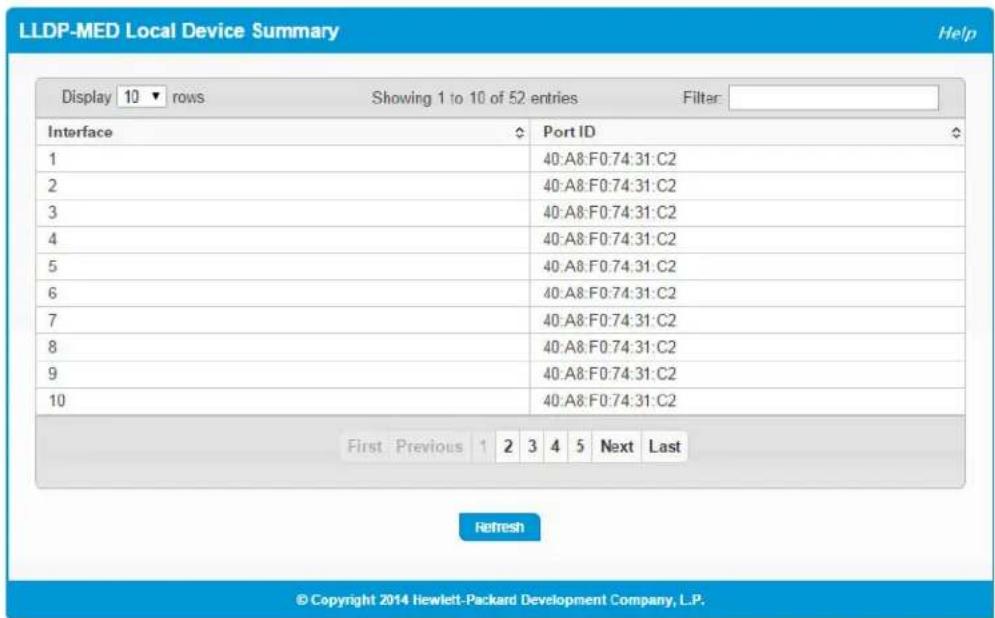
Table 7-9. LLDP-MED Local Device Summary Fields
| Field Description |
| Interface The trunk or port ID. |
| Port ID The interface identifier, which is its physical address. |
LLDP-MED Remote Device Summary
Use the LLDP-MED Remote Device Summary page to view information about the remote devices the local system has learned through the LLDP-MED data units received on its interfaces. Information is available about remote devices only if an interface receives an LLDP-MED data unit from a device.
To display this page, click LLDP-MED > Remote Devices in the navigation pane.
Figure 7-8. LLDP-MED Remote Device Summary Page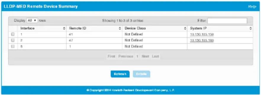
Table 7-10. LLDP Remote Device Summary Fields
| Field Description | |
| Interface | The local interface that has received LLDP-MED data units from remote devices. |
| Remote ID | The client identifier assigned to the remote system that sent the LLDP-MED data unit. |
| Device Class | The MED Classification advertised by the TLV from the remote device. The following three classifications represent the actual endpoints:Class I Generic (for example, IP Communication Controller)Class II Media (for example, Conference Bridge)Class III Communication (for example, IP Telephone)The fourth device is Network Connectivity Device, which is typically a device such as a LAN switch or router, IEEE 802.1 bridge, or IEEE 802.11 wireless access point. |
| System ID | The reported management IP addresses of the remote device. |
Displaying Remote Device Details
To view additional information about a remote device, select the interface that received the LLDP-MED data and click Details.
Link Layer Discovery Protocol (LLDP and LLDP-MED)
LLDP-MED Remote Device Summary
Figure 7-9. LLDP-MED Remote Device Information Page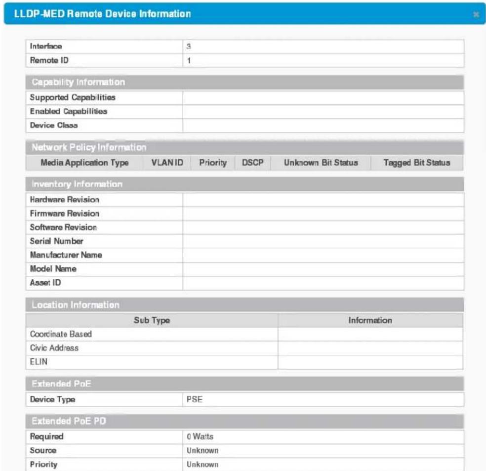

The following additional fields appear on the LLDP-MED Remote Device Information page:
| Field Description | |
| Supported Capabilities | The supported capabilities that were received in the MED TLV on this interface. |
| Enabled Capabilities | The supported capabilities on the remote device that are also enabled. |
| Device Class | The MED Classification advertised by the TLV from the remote device. |
| Network Policy Information | |
| This section describes the information in the network policy TLVs received in the LLDP-MED frames on this interface. | |
| Media Application Type | The media application type received in the TLV from the remote device. The application types are unknown, voicesignaling, guestvoice, guestvoicesignalling, softphonevoice, videoconferencing, streammingvideo, vidosignalling. Each application type that is transmitted has the VLAN ID, priority, DSCP, tagged bit status and unknown bit status.The port on the remote device may transmit one or many such application types. This information is displayed only when a network policy TLV has been received. |
| VLAN ID The VLAN ID associated with a particular policy type. | |
| Priority | The user priority associated with a particular policy type. |
| DSCP | The Differentiated Services Code Point value associated with a particular policy type. |
| Unknown Bit Status | The unknown bit associated with a particular policy type. |
| Tagged Bit Status | Identifies whether the network policy is defined for tagged or untagged VLANs. |
| Inventory Information | |
| This section describes the information in the inventory TLVs received in the LLDP-MED frames on this interface. | |
| Hardware Revision | The hardware version advertised by the remote device. |
| Firmware Revision | The firmware version advertised by the remote device. |
| Software Revision | The software version advertised by the remote device. |
| Serial Number The serial number advertised by the remote device. | |
| Manufacturer Name | The name of the system manufacturer advertised by the remote device. |
| Model Name | The name of the system model advertised by the remote device. |
| Asset ID The system asset ID advertised by the remote device. | |
| Location Information | |
| This section describes the information in the location TLVs received in the LLDP-MED frames on this interface. | |
| Sub Type | The type of location information advertised by the remote device.Coordinate Based—The location map coordinates (latitude, longitude and altitude) of the device.Civic Address—The civic or street address location of the device.ELIN—The Emergency Call Service (ECS) Emergency Location Identification Number (ELIN) of the device. |
| Information | The text description of the location information included in the subtype. |
| Extended PoE | |
| This section describes whether the remote device is advertised as a PoE device. | |
| Device Type | If the remote device is a PoE device, this field identifies the PoE device type of the remote device connected to the port. |
Link Layer Discovery Protocol (LLDP and LLDP-MED)
LLDP-MED Remote Device Summary
| Field Description | |
| Extended PoE PD | |
| This section describes the information about the remote PoE powered device. | |
| Required | If the remote device is a PoE device, this field details the remote ports PD power requirement in Watts. |
| Source | If the remote device is a PoE device, this field details the remote ports PoE PD power source. |
| Priority | If the remote device is a PoE device, this field details the remote ports PD power priority. |
Power Over Ethernet
Power Over Ethernet (PoE) functionality is supported on certain HP 1820 switch models, enabling designated switch ports to provide power to connected devices. The devices receiving power through PoE are referred to as powered devices (PDs).
The switch automatically detects the presence of a PD on a PoE-enabled port, and the switch can learn power requirements from LLDP messages from the PD. Power allocation can also be configured statically per port.
The PoE software supports sharing the available power among the PoE-enabled ports. Ports are assigned one of three configurable PoE priority values (High, Low, and None). When more power is requested than is available on the switch, the switch provides power to high priority ports before lower priority ports.
Power allocation can be scheduled so that power is supplied only during periods when the PD is actually in use.
PoE Capabilities
The HP 1820 PoE-enabled switches support the original PoE specification (IEEE 802.3af) and the PoE Plus specification (IEEE 802.1at). IEEE 802.3af enables providing up to 15.4W of power over a PoE port, whereas PoE Plus enables providing up to 30W of power.
Table 8-1 shows which ports on each switch support PoE and PoE Plus, along with the maximum power the switch can provide to all PoE ports combined.
Table 8-1. PoE Ports and Power Capabilities
| Switch Ports that Support PoE Ports that Support PoE Plus | Maximum Power Available to All Ports |
| 8-Port PoE Plus Ports 1–4 Any two of Ports 1–4 65W | |
| 24-Port PoE Plus Ports 1–12 Any 6 of Ports 1–12 185W | |
| 48-Port PoE Plus Ports 1–24 Any 12 of Ports 1–24 370W |
The maximum power that the switch can provide is configurable on a per-port basis.
PoE Configuration
Use the PoE Configuration page to view global PoE settings. To display this page, click Power Over Ethernet > Configuration in the navigation pane.
Figure 8-1. PoE Configuration Page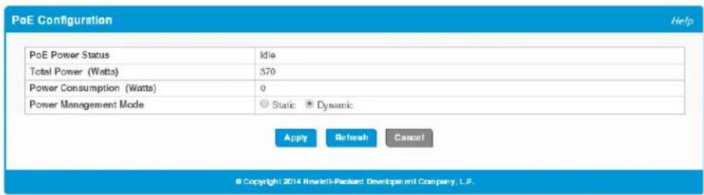
Table 8-2. PoE Configuration Fields
| Field Description | |
| PoE Power Status | The current status of the switch PoE functionality. Possible values are:Delivering—At least one port on the switch is delivering power to a connected device.Idle—The PoE functionality is operational but no ports are delivering power.Faulty—The PoE functionality is not operational. |
| Total Power (Watts) The total power in watts that can be provided by the switch. | |
| Power Consumption (Watts) | The amount of power in watts currently being consumed by connected PoE devices. |
| Power Management Mode | Select the method by which the PoE controller determines supplied power. Possible values are:Static—The power allocated to each port is reserved and is not available to any other port, even when less than the maximum allocation is being used.Dynamic—The power allocated to each port is not reserved. Unused power may be allocated from one port to another as needed, up to the power limit defined for each port. This is the default selection.Note: In either mode, High Power Mode must be enabled on the port when PoE+ functionality is required. See “PoE Port Configuration” on page 8-3. |
Click Apply to save any changes for the current boot session. The changes take effect immediately.
PoE Port Configuration
You can use the PoE Port Configuration page to administratively enable or disable PoE on ports that support it and to configure the port priority and other settings. To display this page, click Power Over Ethernet > Port Configuration in the navigation pane.
Figure 8-2. PoE Configuration Page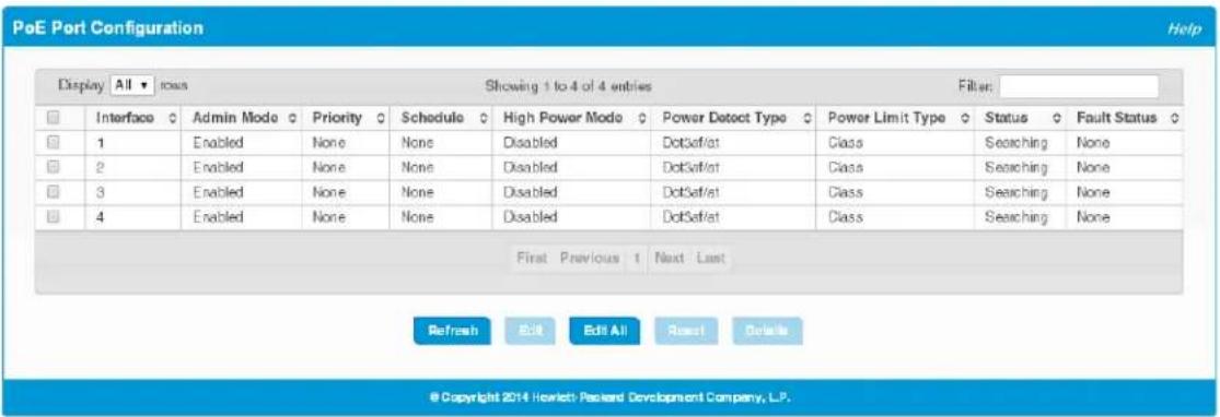
The following settings display for each port that supports PoE.
Table 8-3. PoE Configuration Fields
| Field Description | |
| Interface The port number. | |
| Admin Mode | Indicates whether PoE is administratively enabled or disabled on the port. This feature is enabled by default on ports that support PoE. |
| Priority | The priority of the port when allocating available power. Power is delivered to the higher-priority ports when needed before providing it to the lower priority ports. Possible values are High, Low, and Nonc. Nonc is the lowest priority and the default for all ports. |
| Schedule | The scheduled time, if any, when source power is available on this port. Options are:• None—Source power is available at all times (subject to the port priority). This is the default selection.• Schedule 1—Source power is available during the configured first schedule.• Schedule 2—Source power is available during the configured second schedule.You can configure schedules on the PoE Port Schedule page. |
| High Power Mode | When enabled, the port supports the original PoE standard and the PoE+ standard, which allows for providing up to 30W of power. When disabled, the port supports the original PoE standard only, which allows for providing up to 15.4W of power. This setting is disabled by default.If PoE+ functionality is required, this setting must be enabled on the port, even when the switch is configured to operate in Dynamic Power Management mode (see “PoE Configuration” on page 8-2). |
| Power Detect Type | The PD detection mechanism performed by the PSE port. Possible value arc:• Dot3af/at—The 4-point detection scheme defined in IEEE 802.3af is used. This is the default option.• Dot3af/at + Pre-Standard—The 4-point detection scheme defined in IEEE 802.3af is used. If this mechanism fails to detect a connected PD, Dot3af/at detection is used. |
| Power Limit Type | The type of power limiting used for the port. Possible values are:Class—The device class determines the power limit. The switch learns the class of the device through the receipt of LLDP messages. This is the default selection.User—The power limit is user-defined, overriding the LLDP information.When set to User, the specified power limit also displays next to this value. When High Power Mode is enabled, the maximum value is 30W. When High Power Mode is disabled, the maximum value is 15.4W. (The Power Limit field is available on the Edit PoE Port Configuration page.) |
| Status | The status of the port as a provider of power over Ethernet. Such devices are referred to as power-sourcing equipment (PSE). Possible values are:Disabled—The PSE is disabled.Delivering Power—The PSE is delivering power.Fault—The PSE has experienced a fault condition.Test—The PSE is in test mode.Other Fault—The PSE has experienced a variable error condition.Searching—The PSE is transitioning between states.Requesting Power—The PSE is currently not able to deliver power because power is unavailable to the port. |
| Fault Status | The fault status, if a fault occurred. Possible values are:NoneShortOverloadPower Denied |
Modifying Port PoE Settings
To change PoE settings for a port, select the checkbox associated with it and click Edit. To configure the same settings for all PoE-enabled ports, click Edit All.
Click Apply to save any changes for the current boot session. The changes take effect immediately.
Viewing PoE Port Details
To view additional PoE configuration information for a port, select the port and click Details.
Figure 8-3. PoE Port Details Page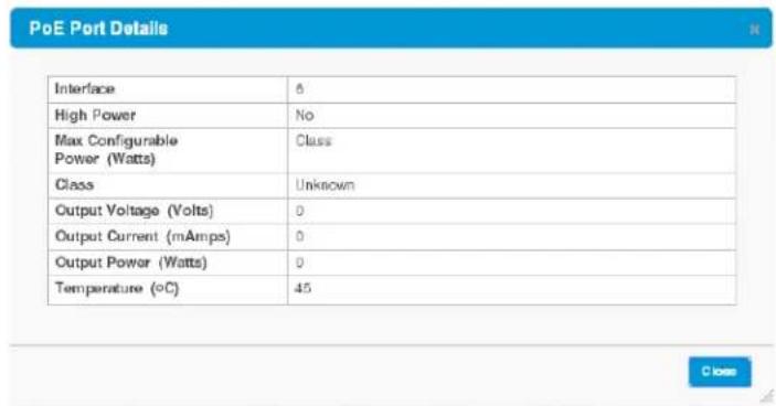
Table 8-4. PoE Port Details Fields
| Field Description | |
| Interface The port number. | |
| High Power | Indicates whether high-power mode is enabled or disabled. When enabled, the port supports the the PoE+ power standard, which allows for providing up to 30W of power. When disabled, the port supports the original PoE standard only, which allows for providing up to 15.4W of power. |
| Max Configurable Power | If the Power Limit Type for the port is User (user-defined), this field displays the configured power limit. If the Power Limit type is set to Class, then Class displays. |
| Class | If the Power Limit Type is set to Class, this field displays the class of the connected device, as learned in LLDP messages. Possible values are Unknown and Class 0 through Class 4. A higher class value indicates that the device requires higher power. |
| Output Voltage The voltage being applied to the connected device. | |
| Output Current | The current in milliamps being drawn by the powered device. |
| Output Power | The power in watts being drawn by the connected device. |
| Temperature The temperature measured at the PoE port. | |
PoE Port Schedule
You can configure schedules for the allocation of power to PoE ports. Two built-in schedules, Schedule 1 and Schedule 2, are available for configuration. Schedules consist of one or more time periods when PoE power is to be supplied.
Time periods can be periodic or absolute. A periodic entry occurs at the same time every day or on one or more days of the week. An absolute entry does not repeat. Each schedule can have multiple periodic entries but only one absolute entry. Up to 10 time periods can be configured per schedule.
To display the PoE Port Schedule page, click Power Over Ethernet > Schedule in the navigation pane.
Figure 8-4. PoE Port Schedule Page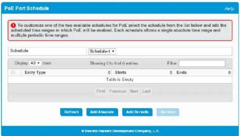
Table 8-5. PoE Port Schedule Fields
| Field Description | |
| Schedule | Select Schedule-1 or Schedule-2 to display information on time periods configured for the schedule, if any. |
| Entry Type The type of time period entry, which is one of the following:Absolute—A single time period that occurs once or has an undefined start or end period.The duration of an absolute entry can be hours, days, or even years. Each time entry configuration can have only one entry.Periodic—A recurring entry that takes place at fixed intervals. This type of entry occurs at the same time on one or more days of the week. | |
| Starts | For an absolute entry, this field indicates the time, day, month, and year that the entry begins.If this field is blank, the absolute entry became active when it was configured.For a periodic entry, this field indicates the time and day(s) of the week that the entry begins. |
| Ends | For an absolute entry, indicates the time, day, month, and year that the entry ends. If this field is blank, the absolute entry does not have a defined end.For a periodic entry, this field indicates the time and day(s) of the week that the entry ends. |
To configure a schedule, select the schedule from the Schedule list, then click Absolute or Periodic. If the Absolute button is not available, an absolute entry already exists for the selected schedule.
Configuring an Absolute Time Period
To configure an absolute schedule, select the schedule from the Schedule list and click Add Absolute.
Figure 8-5. Add Absolute Time Period Page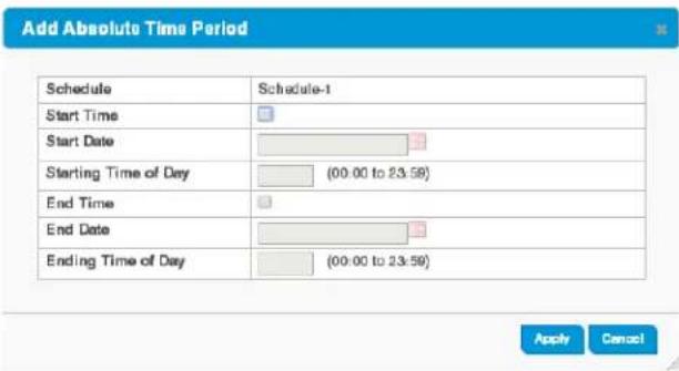
Table 8-6. Add Absolute Time Period Fields
| Field Description | |
| Schedule The schedule to be configured. | |
| Start Time | Select this option to configure values for the Start Date and the Starting Time of Day fields. If this option is not selected, the entry becomes active immediately. It is not selected by default. |
| Start Date | Click the calendar icon to select the day, month, and year when this entry becomes active. This field can be configured only when the Start Time option is selected. |
| Starting Time of Day | Specify the time of day that the entry becomes active by entering the information in the field or by using the scroll bar in the Choose Time window, which displays when you click the field. You can click Now to use the current time of day. Click Done to close the window. |
| End Time | Select this option to configure values for the End Date and Ending Time of Day fields. If this option is not selected, the entry does not have an end time; after the time period starts, it will remain active indefinitely. |
| End Date | Click the calendar icon to select the day, month, and year when this entry should no longer be active. |
| Ending Time of Day | Specify the time of day that the entry becomes inactive by entering the information in the field or by using the scroll bar in the Choose Time window, which displays when you click the field. Click Now to use the current time of day. Click Done to close the window. |
Click Apply to save any changes for the current boot session. The changes take effect immediately.
Adding a Periodic Time Period
To configure a periodic schedule, select the schedule from the Schedule list and click Add Periodic.
Note
Periodic time periods cannot overlap. Consecutive periodic time periods must be at least three minutes apart.
Figure 8-6. Add Periodic Time Period Page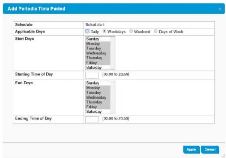
Table 8-7. Add Periodic Time Period Fields
| Field Description | |
| Schedule The schedule to be configured. | |
| Applicable Days | Select the days on which the periodic time range entry is active. If you selectDays of Week, you can select multiple days from the Start Days list. |
| Start Days | Indicates the days on which the time period becomes active. The days are autoselected to correspond to your choice in theApplicable Daysfield.If you selectedDays of Week, you can hold down theCtrlkey to select multiple days. |
| Starting Time of Day | Specify the time of day that the entry becomes active by entering the information in the field or by using the scroll bar in the Choose Time window, which displays when you click the field. You can clickNowto use the current time of day. ClickDoncto close the window. |
| End Days | Indicates the days on which the time entry ends. The days are autoselected to correspond to your choice in theApplicable Days.If you selectedDays of Week, the selected days correspond to your selections in the Start Dayslist. |
| Ending Time of Day | Specify the time of day that the entry becomes inactive by entering the information in the field or by using the scroll bar in the Choose Time window, which displays when you click the field. ClickNowto use the current time of day. ClickDoneto close the window. |
Click Apply to save any changes for the current boot session. The changes take effect immediately.
Security
The HP 1820 series switch software includes a robust set of built-in denial-of-service (DoS) and storm-control protections, and allows configuring secure HTTP (HTTPS) management sessions.
Advanced Security Configuration
The HP 1820 series switch software provides the following built-in security features:
■ Storm Control—This feature protects against conditions where incoming packets flood the LAN, causing network performance degradation. The software includes Storm Control protection for unicast traffic with an unknown destination, and for broadcast and multicast traffic. ■ Auto Denial-of-Service (DoS) protections—A DoS attack is an attempt to saturate the switch with external communication requests to prevent the switch from performing efficiently, or at all. You can enable Auto DoS protection that prevents common types of DoS attacks.
Caution
The DoS feature does not generate any notifications (such as error messages, syslog messages, SNMP traps) if a DoS attack occurs.
To display the Advanced Security page, click Security > Advanced Security in the navigation pane.
Figure 9-1. Advanced Security Configuration Page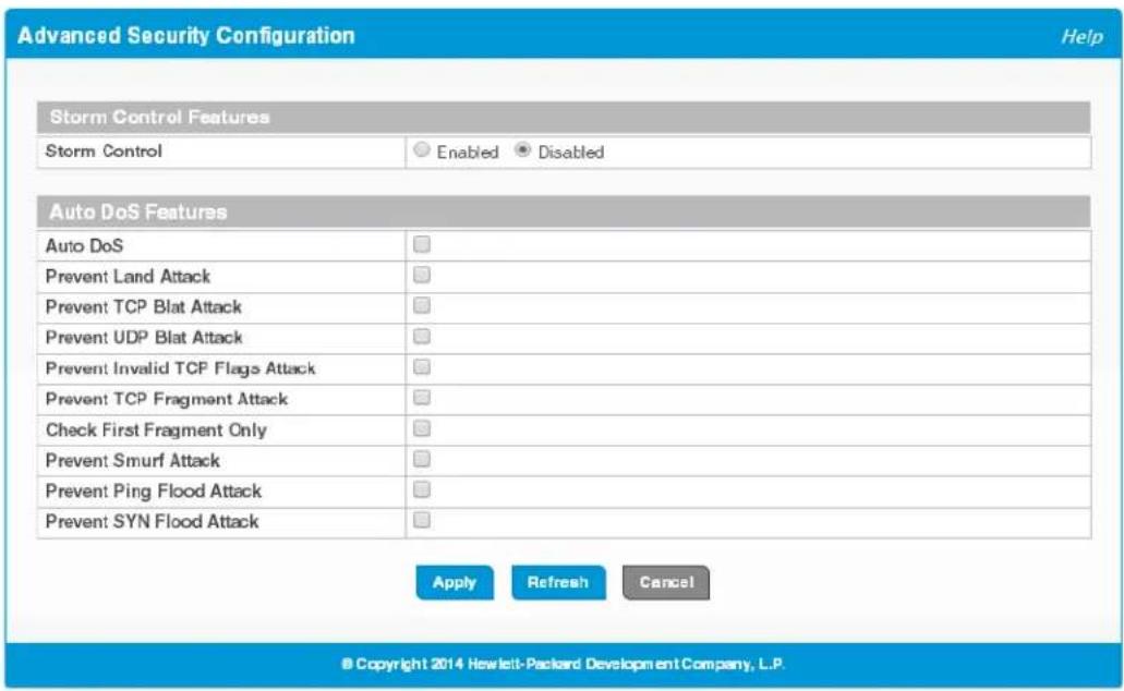
Table 9-1. Advanced Security Configuration Fields
| Field Description | |
| Storm Control Features | |
| Storm Control | Storm control enables the rate-limiting of incoming unicast (with unknown destination), multicast, and broadcast traffic to prevent unnecessary congestion in the network. When enabled, the storm control threshold is automatically set to 5% of port speed. If the incoming rate of unicast (with unknown destination), multicast, or broadcast packets exceeds this value, the port discards the excess traffic until the rate for that particular packet type falls below the threshold.Note: The threshold percentage is translated to a packets-per-second value that is used by the switch hardware to rate-limit the incoming traffic. This translation assumes a nominal 512 byte packet size to determine the packets-per-second threshold based on the port speed. For example, the 5% threshold applied to a 1 Gbps port equates to approximately 11748 packets-per-second, regardless of the actual packet sizes being received by the port. Each of the three storm control packet types is rate-limited independently. |
| Auto Dos Features | |
| Auto DoS | Enable this option to enable all the DoS prevention mechanisms with default values. Enabling this feature makes all the fields in the remainder of the table inaccessible (grayed-out). When disabled, you can individually turn on and off the DoS features and change their default values. This feature and all the individual DoS protections are disabled by default. |
| Prevent Land Attack | Enable this option to drop packets for which the source IP address equals the destination IP address. |
| Prevent TCP Blat Attack | Enable this option to drop packets for which the TCP source port equals the TCP destination port. |
| Prevent UDP Blat Attack | Enable this option to drop packets that have a UDP source port equal to the UDP destination port. |
| Prevent Invalid TCP Flags Attack | Enable this option to drop packets that have TCP Flags SYN and FIN set. |
| Prevent TCP Fragment Attack | Enable this option to drop IP packets that have an IP fragment offset equal to 1. |
| Check First Fragment Only | Enable this option to drop packets that have a TCP header smaller than the minimum TCP header size, which is hard-coded to 20 bytes. |
| Prevent Smurf Attack | Enable this option to drop ICMP Echo packets (ping) that are sent to a broadcast IP address. |
| Prevent Ping Flood Attack | Enable this option to prevent ping flooding by limiting the number of ICMP ping packets. |
| Prevent SYN Flood Attack | Enable this option to limit the rate of TCP connection requests so that they are not received faster than they can be processed. |
Click Apply to save any changes for the current boot session. The changes take effect immediately.
Secure Connection
The HP 1820 series switch software allows the administrator to enable or disable Secure HTTP protocol (HTTPS). When enabled, the administrator can establish a secure connection with the switch using the Secure Sockets Layer (SSL) protocol. Secure HTTP can help ensure that communication between the management system and the switch is protected from eavesdropping and man-in-the-middle attacks. The HP 1820 series switch software supports SSL v1.0.
You can upload an SSL certificate to the switch or have the switch generate its own certificate. The SSL certificate functions as a digital passport, enabling client web browsers to verify the identity of the switch before accessing it.
Note
SSL is described in client/server terminology, where the SSL-enabled switch is the server and a web browser is the client.
The certificate provides information to the browser such as the server name, the trusted certificate authority (CA) that issued the certificate, the date it was issued, and the switch's public key.
The browser and server use this information to negotiate a secure connection in the following manner:
The browser verifies the certificate authority's authenticity by checking it against its own list of CAs. (Web browsers such as Microsoft Internet Explorer and Mozilla Firefox maintain data on trusted CAs.) After validating the CA, the browser and switch negotiate the highest level of security available to both. The browser uses the public key to encrypt a random number and send it to the switch. The switch uses a private key stored in memory (not advertised on the certificate) to decrypt it. From this process, the browser and switch determine an algorithm for encrypting and decrypting all further communication during the HTTPS session.
To enable secure HTTPS connections via SSL, the HTTPS Admin mode must be enabled on the switch, and the web server must have a public key certificate. The switch can generate its own certificates, or you can generate these externally and upload them to the switch.
Certificates generated by the switch are self-signed; that is, the validity of the information provided in the certificate is attested to by the switch itself.
Uploaded certificates can also be self-signed (by a server other than the switch), or they can be root certificates. A root certificate has been digitally signed by a CA, and is therefore considered to provide a higher level of security.
You can also upload the encryption parameter files that provide algorithms for encrypting the key exchanges.
To display the Secure HTTP Configuration page, click Security > Secure Connection in the navigation pane.
Figure 9-2. Secure HTTP Configuration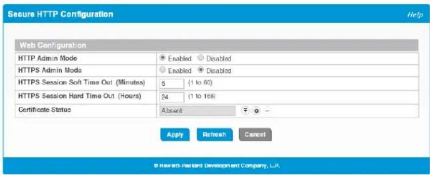
Table 9-2. Secure HTTP Configuration Fields
| Field Description | |
| HTTP Admin Mode | Enable the Administrative mode of HTTP. This feature is enabled by default and can only be disabled when the HTTPS Admin mode is enabled. |
| HTTPS Admin Mode | Enable to allow secure HTTPS sessions. When enabled, ensure that the Certificate Status field reflects that a certificate is present. This feature is disabled by default. Note that you can only upload SSL certificates when this mode is disabled. |
| HTTPS Session Soft Time Out | The number of minutes after which an HTTPS session times-out if there is no user activity. The default value is 5 minutes. |
| HTTPS Session Hard Time Out | The number of minutes after which an HTTPS session times-out, regardless of recent user activity. The default value is 24 hours. |
| Certificate Status | The status of the SSL certificate generation process:Present—A certificate is available for use with HTTPS sessions.Absent—No certificate is available on the switch. This is the default value.Generation in Progress—An SSL certificate is currently being generated. |
Note
Upload or regenerate a certificate when the previous certificate has expired, or when you have reason to suspect that security has been breached and the certificate has been taken for use by another server.
If you click the upload icon, the Upload Certificates page displays. See "Uploading SSL Certificates and Encryption Files" on page 9-5. If you click the regenerate icon, the switch creates its own self-signed public key certificate. The status of the process displays in the Status field. If the value of the Certificate Status field is Present, you can click the delete icon to delete the existing certificate. If you enable or disable HTTPS Admin Mode, or change the timeout settings, click Apply to save the changes for the current boot session. The changes take effect immediately.
Uploading SSL Certificates and Encryption Files
You can upload a public key certificate that has been signed by another server, or a root certificate that has been signed by a certificate authority. You can also upload Diffie-Hellman (DH) encryption parameter files, which establish the algorithms for encrypting key exchanges.
Before you upload a file to the switch, the following conditions must be met:
The file is on the server in the appropriate directory.
The file is in the correct format.
The switch has a path to the server.
Use the following procedure to upload an SSL certificate or DH files to the switch.
- If enabled, set the HTTPS Admin Mode to Disabled.
- Click ↑.
The Upload Certificates page displays.
Figure 9-3. Upload Certificates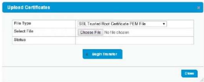
- Select one of the following from the File Type field:
- SSL Trusted Root Certificate PEM File — A PEM-encoded SSL certificate that has been digitally signed by a certificate authority.
- SSL Server Certificate PEM File — A PEM-encoded SSL certificate that has been signed by another server.
- SSL DH Weak/Strong Encryption Parameter PEM File — DH certificates provide the algorithms for encrypting key exchanges and are used independent of the certificate. The weak version uses a cipher strength of 512 bits and the strong version uses a cipher strength of 1024 bits. Browser settings determine which DH file parameters are requested at the start of the SSL session.
- Browse for the file on your local computer or network.
- Click Begin Transfer.
The status of the transfer displays in the Status field.
- Enable HTTPS Admin Mode and click Apply.
Green Features
The green features on the switch are Efficient Ethernet (EEE) technologies, as defined by the IEEE 802.3az task force. These features are designed to reduce per-port power usage by shutting down ports when no link is present or when activity is low.
Green Features Configuration
To display the Green Features configuration page, click Green Features > EEE Configuration in the navigation pane.
Figure 10-1. Green Features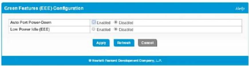
Table 10-1. Green Features Configuration Fields
| Field Description | |
| Port Energy Saving Configuration | |
| Auto Port Power-Down | When this feature is enabled and the port link is down, the PHY automatically goes down. The port wakes up when it senses activity on the link. This features enables saving power consumption when no link partner is present. This feature is disabled by default. |
| Low-Power Idle (EEE) | EEE (Energy Efficient Ethernet) is designed to save power by turning off network ports that are not passing traffic. EEE works for ports in auto-negotiation mode, where the port is negotiated to either 100 Mbps Full Duplex or 1 Gbps (1000 Mbps) Full Duplex. This feature is disabled by default. |
Click Apply to save any changes for the current boot session. The changes take effect immediately.
EEE Status
When EEE is enabled, you can use the EEE status page to view estimated power savings and power consumption information. This page also displays status information for each interface.
To display the EEE status page, click Green Features > EEE Status in the navigation pane.
Figure 10-2. EEE Status Page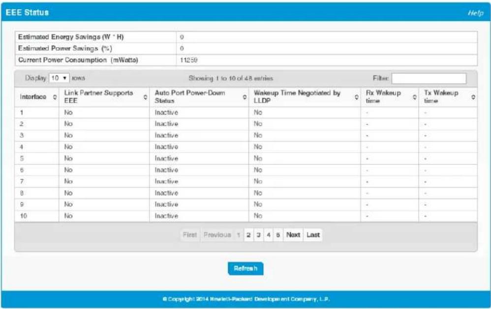
Table 10-2. EEE Status Fields
| Field Description | |
| Global Statistics | |
| Estimated Energy Savings | The estimated cumulative energy saved on the device (in watts x hours) due to the Green Ethernet feature. |
| Estimated Power Savings | The estimated percentage of power saved on all ports due to the Green Ethernet feature. For example, 10% means that the device required 10% less power. |
| Current Power Consumption | The estimated power consumption by all ports. |
| Per-Port Status | |
| Interface The interface ID. If EEE is not enabled, then no interfaces display. | |
| Link Partner Supports EEE | Displays Yes if the interface has received EEE messages (called Type-Length Values, or TLVs) from a link partner, or No if it has not. |
| Auto Port Power-Down Status | The current operational state of Auto Port Power-Down mode. |
| Wakeup Time Negotiated by LLDP | Indicates whether the EEE wakeup time is negotiated with the link partner (Yes or No). |
| Rx Wakeup time | The Rx wakeup time in effect for thee port, if negotiated by LLDP (otherwise, a dash displays). |
| Tx Wakeup time | The Tx wakeup time in effect for the port, if negotiated by LLDP (otherwise, a dash displays). |
Diagnostics
You can use the Diagnostics pages to test, reboot, and view log and configuration information on the HP 1820 series switch.
Buffered Log
The log messages the switch generates in response to events, faults, errors, and configuration changes are stored locally on the switch in the RAM (cache). This collection of log files is called the RAM log or buffered log. When the buffered log file reaches the configured maximum size, the oldest message is deleted from the RAM when a new message is added. If the system restarts, all messages are cleared. The Log page displays the 100 most recent system messages, such as configuration failures and user sessions. The newest log entry, by default, is displayed at the bottom of the list.
Note
If more than 100 messages accumulate, their Log Index numbers continue to increment beyond 100 and the oldest entries are deleted (for example, if 200 log entries were generated since the system was last restarted or the log file was cleared, then the log file would display entries 101 to 200).
To display the Log page, click Diagnostics > Log in the navigation pane.
Figure 11-1. Buffered Log Page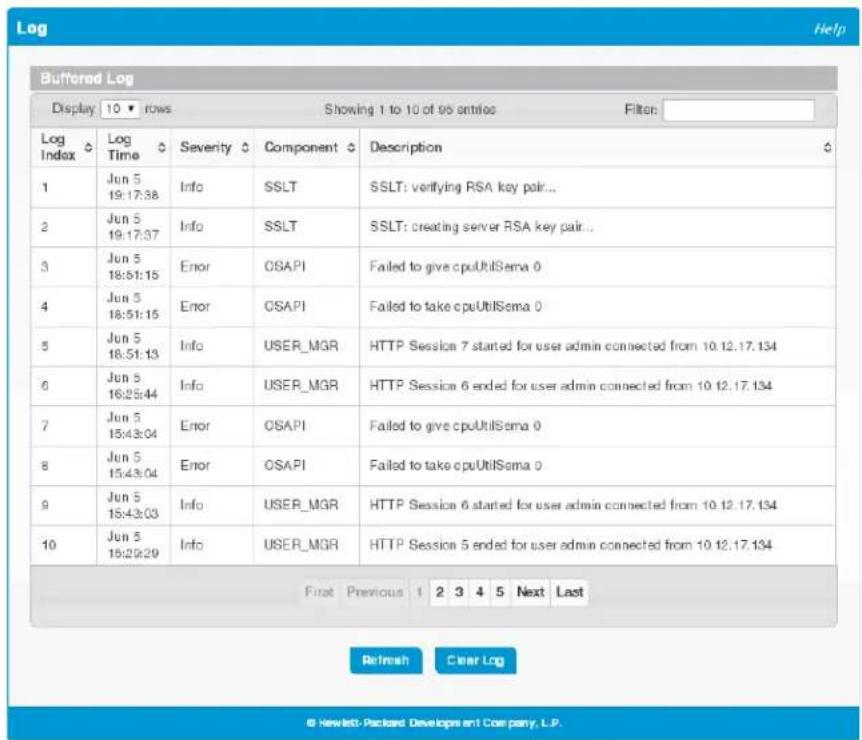
If there has been an unexpected restart of the switch (that is, a restart not caused by a power loss), a text box displays near the top of the page to alert the user of the event. The Crash Log text box displays information about the restart event, which may be helpful to technical support in diagnosing its cause.
To clear the unexpected restart alert and the contents of the crash log, click Clear Unexpected Restart. You can click Save Crash Log to save download the contents of the crash log to a file in tar.gz format (a compressed archive).
The following information displays in the Buffered Log table.
Table 11-1. Buffered Log Fields
| Field Description |
| Log Index The log number. |
| Log Time Time at which the log was entered in the table. |
| Severity The severity level associated with the log message. The severity can be one of the following:Emergency (0)—The device is unusable.Alert (1)—Action must be taken immediately.Critical (2)—The device is experiencing primary system failures.Error (3)—The device is experiencing non-urgent failures.Warning (4)—The device is experiencing conditions that could lead to system errors if no action is taken.Notice (5)—The device is experiencing normal but significant conditions.Info (6)—The device is providing non-critical information.Debug (7)—The device is providing debug-level information. |
Field Description
Component The system component that issued the log entry.
Description A text description of the entry.
- Click the arrows next to the column headings to sort the list by the column, in ascending or descending order. ■ Click Clear Log to delete all log messages.
For information on configuring log settings, see "Log Configuration" on page 11-3.
Log Configuration
The HP 1820 series switch software supports logging system messages to the buffered log file or forwarding messages over the network using the Syslog protocol. Syslog messages can be captured by a designated host on the network that is running a Syslog daemon. You can use the Log Configuration page to configure buffered log and Syslog settings.
To display the Log Configuration page, click Diagnostics > Log Configuration in the navigation pane.
Figure 11-2.Log Configuration Page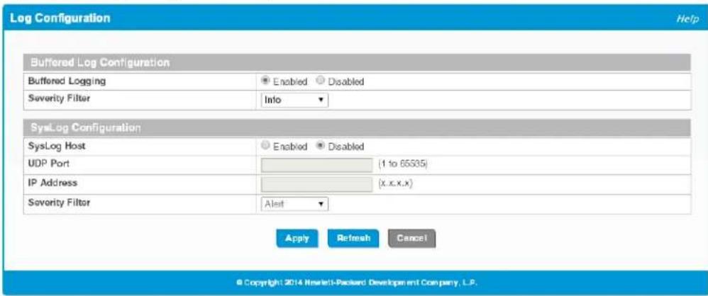
Table 11-2. Log Configuration Fields
| Field Description | |
| Buffered Log Configuration | |
| Buffered Logging | Enables or disables logging system events to the buffered log. This feature is enabled by default. |
| Severity Filter | Specify type of system messages logged using the Buffered Logging Level setting:Emergency—Alerts the user of the highest level of system error classified as urgent.Alert—Alerts the user of a high level of system error.Critical—Alerts the user of a high level of system error which must be immediately addressed.Error—Alerts the user of an error in the system.Warning—Warns the user of an impending system error of a specified operation.Notice—Notifies the user of a system error.Info—Provides the user with system information. This is the default filter level.Debug—An internal note to reconcile programming code. |
| SysLog Configuration | |
| SysLog Host | Enables and disables logging to configured syslog hosts. When the syslog admin mode is disabled, the device does not relay logs to syslog hosts, and no messages are sent to any collector/relay. When enabled, messages are sent to configured collectors/relays using the values configured for each collector/relay. This feature is disabled by default. |
| UDP Port | The UDP port on the logging host to which syslog messages are sent. The port ID can be any value from 1 to 65535. |
| IP Address | The IP address of the remote host to receive log messages. |
| Severity Filter | The severity level threshold for log messages. All log messages with a severity level at and above the configured level are forwarded to the logging host. By default, alerts designated as Critical and higher are forwarded to the SySLog host. |
Click Apply to save any changes for the current boot session. The changes take effect immediately.
Ping Test
Use the Ping page to send one or more ping requests from the switch to a specified IP address. You can use the ping request to check whether the switch can communicate with a particular host on an IP network. A ping request is an Internet Control Message Protocol (ICMP) echo request packet. The information you enter on this page is not saved as part of the device configuration.
To display the Ping page, click Diagnostics > Ping Test in the navigation pane.
Figure 11-3. Ping Page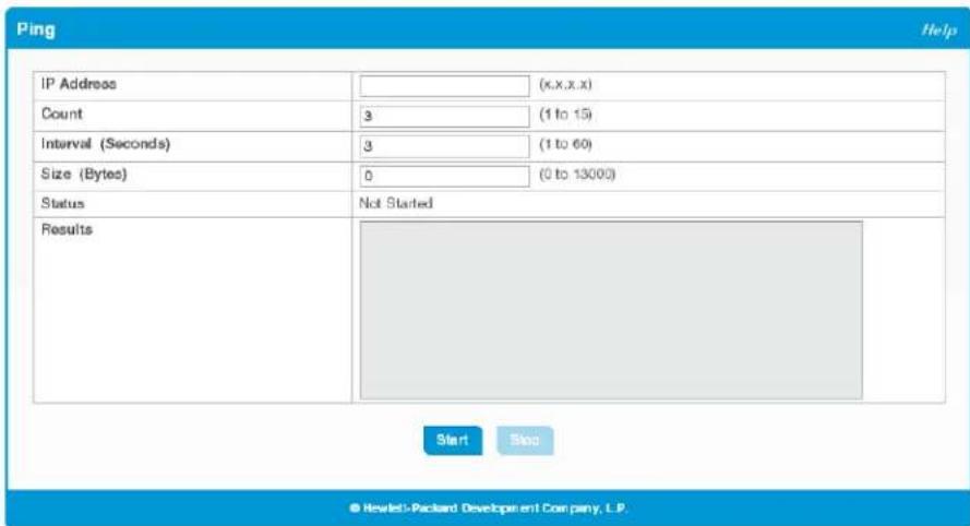
Table 11-3. Ping Fields
| Field Description | |
| IP Address Specify the IP address you want to reach. | |
| Count | Specify the number of packets to send. The range is 1 to 5 packets and the default is 1 packet. |
| Interval | Specify the delay between ping packets. The range is from 1 to 60 seconds and the default is 3 seconds) |
| Size | Specify the size of the ping packet to be sent. Changing the size allows you to troubleshoot connectivity issues with a variety of packet sizes, such as large or very large packets. The range is from 0 to 13000 bytes and the default is 0 bytes). |
| Status | The current status of the ping test, which can be one of the following:Not Started—The ping test has not been initiated since viewing the page.In Progress—The ping test has been initiated and is running.Stopped—The ping test was interrupted because the user clicked theStopbutton.Donc—The test has completed, and information about the test is displayed in theResultsarea. |
| Results | The results of the ping test, which includes the following information:The IP address of the device that was pinged.The Internet Control Message Protocol (ICMP) number of the packet, starting from 0.The time it took to receive a reply, in microseconds.The number of ping packets sent and received, the percent of packets that were lost, and the minimum, average, and maximum round-trip time for the responses in milliseconds. |
Click Start to ping the specified host and Stop to end a ping in progress.
Reboot Switch
Use this feature to perform a software reboot of the switch. If you applied configuration changes, click the Save Configuration button in the upper right of any page before rebooting. If the switch is configured to use DHCP to acquire its IP address, the address may change upon restart; you will need to determine the address before logging back in to the management utility.
To display the Reboot Switch page, click Diagnostics > Reboot Switch.
Figure 11-4. Reboot Switch Page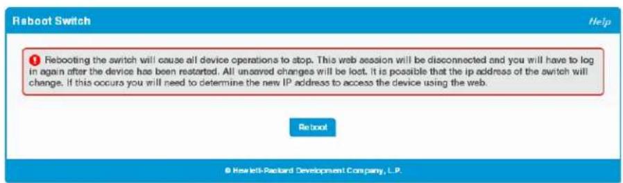
Click Reboot to reboot the switch.
Factory Defaults
You can use the Reset Configuration page to restore all settings to their factory default values. All configuration changes, including those that were previously saved, are reset in the running system by this action. If the switch is configured to use DHCP to acquire its IP address, the address may change upon restart; you will need to determine the address before logging back in to the management utility.
To display the Factory Defaults page, click Diagnostics > Factory Defaults.
Caution
It is recommended that you back up the current configuration file prior to restoring the factory defaults configuration. See “Backup and Update Manager” on page 12-2 for instructions.
Figure 11-5. Reset Configuration Page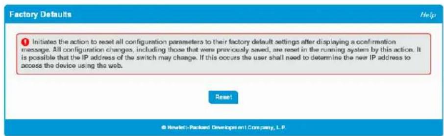
Click Reset to restore the system to the default settings.
Support File
Use the support file page to display summary information for the switch on a single page.
To display the Support File page, click Diagnostics > Support File in the navigation pane. Figure 11-6 shows a partial view of the page.
Figure 11-6. Support File Page
The support file page includes the following information:
■ System Information— A system description, name, location, and contact information, along with date and time information
■ Device Information—Software and OS versions
■ System Resource Usage—CPU and memory usage data
■ Image Status and Image Description—The active and backup image status and versions
■ Buffered Log and Configuration—Messages and logging configuration details
■ Syslog Configuration—Syslog status and remote port and address information
■ Time Configuration and Time Zone—SNTP client status and time zone configuration
Network Details—Switch IP and MAC addresses
Web Parameters and Management Access—Web session timeout and access port and management VLAN information
SNMP—Status and community configuration
Diagnostics Locator
Port Status and Port Summary Statistics—Port and trunk configuration details, summary, and statistics. Trunk Configuration and Trunk Statistics—Trunk configuration details and flap count statistics. Jumbo Frames Configuration—Enable/disable status. Flow Control and Storm Control Configuration—Enable/disable status. Auto Dos Features—Enable/disable status. Web Configuration—HTTP and HTTPS status and timeout settings. MAC Table—Address forwarding table and summary statistics. VLAN Configuration and VLAN Port Membership—Configured VLANs and membership details. Port Mirroring Configuration—Enable/disable status and source and destination port configuration. IGMP Status—Enable/disable information and statistics. LLDP and LLDP-MED Configuration—Global settings and per-port LLDP configuration and activity. Loop Protection Status—Per interface configuration and statistics. Spanning Tree Bridge and Interface Status—Global and per-port configuration and status. Green Features (EEE) Configuration—Global and per-port enable/disable status and power consumption data. PoE Configuration—On switches that support PoE, global and per-port configuration and schedule settings.
You can click Save As to save the Support File page content. The Support File page is saved as HTML and is named support_file.html by default.
Locator
When you need to physically locate the switch, you can use this page to activate a blinking LED on the switch. When enabled, the LED blinks for 30 minutes before being automatically turned off by switch software. You can also use this page to disable the LED if the switch has been located.
To display the Locator page, click Diagnostics > Locator in the navigation pane.
Figure 11-7. Locator Page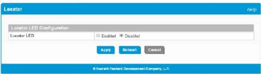
Select Enabled and click Apply to cause the Locator LED on the switch to blink for 30 minutes. This feature is disabled by default.
Note that this setting is not stored with the system configuration, so clearing the configuration will not change this value. If the switch reboots, this value is reset to Disabled.
MAC Table
The MAC address table keeps track of the Media Access Control (MAC) addresses associated with each port. This table enables the switch to forward unicast traffic through the appropriate port. The MAC address table is sometimes called the bridge table or the forwarding database.
To display the MAC Table page, click Diagnostics > MAC Table in the navigation pane.
Figure 11-8. MAC Table Page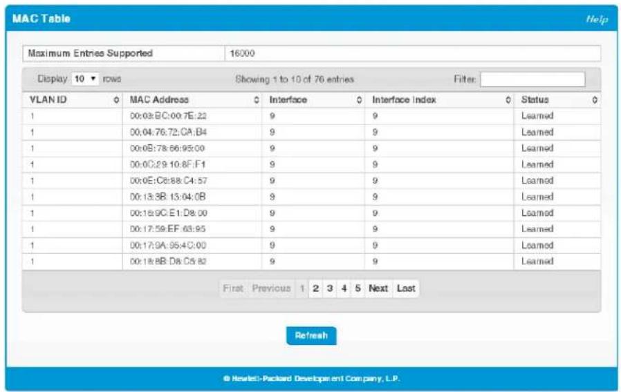
Table 11-4. MAC Table Fields
| Field Description | |
| Maximum Entries Supported | The maximum number of MAC address entries that can be learned on the switch. The 8- and 24-port switches support a maximum of 8,000 entries and the 48-port switches support a maximum of 16,000 entries. |
| VLAN ID The VLAN or VLANs with which the MAC address is associated. | |
| MAC Address | A unicast MAC address for which the switch has forwarding and/or filtering information. The format is a six-byte MAC address, with each byte separated by colons. |
| Interface | The port where this address was learned. The port identified in this field is the port through which the MAC address can be reached. CPU is a special source port used for internal management on the switch |
| Interface Index | The Interface Index of the MIB interface table entry associated with the source port. This value helps identify an interface when using SNMP to manage the switch. |
| Status | Provides information about the entry and why it is in the table. Possible values are the following:•Learned—The address has been automatically learned by the switch and can age out when it is not in use. Dynamic addresses are learned by examining information in incoming Ethernet frames.•Management—The burned-in MAC address of the switch.•Self—The MAC address belongs to one of the physical interfaces on the switch.•Other—The address was added dynamically through an unidentified protocol or method.•Unknown—The switch is unable to determine the status of the entry. |
Maintenance Pages
You can use the maintenance pages to change the password for logging in to the configuration utility, back up and update the switch software, and select which of two software images is the active image and which is the backup image.
Password Manager
Use the Password Manager page to change the password used to access the web interface. To display the Password Manager page, click Maintenance > Password Manager.
Figure 12-1. Password Manager Page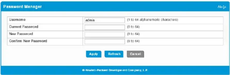
Table 12-1. Password Manager Fields
| Field Description | |
| Username | A unique ID or name used to identify the administrative user account. A change in the username is effective the next time you attempt to log into the switch. |
| Current Password | There is no password by default.Passwords must be at least 8 characters but no more than 64 characters long. Passwords are case sensitive. There is no default password. Passwords must use printable characters and cannot contain a quotation mark (“) or question mark (?). In case of a forgotten password, manually reset the switch to its factory defaults. |
| New Password Confirm New Password | To change the password, enter the old password, if one exists, and enter the new password twice. |
If you change the user name or password, click Apply to save your changes. At the next log on, use the new password.
Backup and Update Manager
The File Transfer page enables you to save a backup copy of the switch's image or configuration files on a local system or network directory and to update files on the switch by transferring newer files from a remote system. Files can be backed up and updated using either HTTP or TFTP.
To display this page, click Maintenance > Backup and Update Manager in the navigation pane.
Figure 12-2. File Transfer Page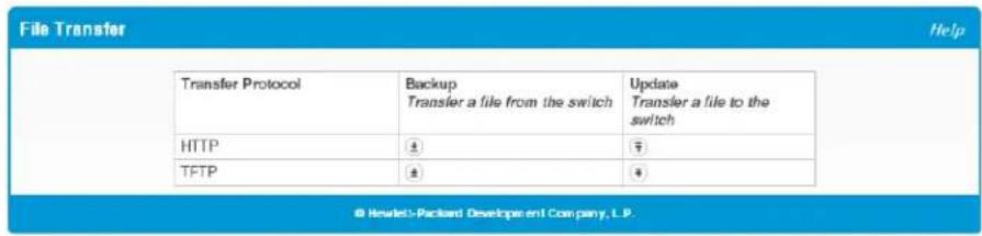
Backing Up Files
To back up a file, click the icon in the Backup column in either the HTTP or TFTP row. The HTTP Backup File or TFTP Backup File page displays.
Figure 12-3. HTTP Backup File Page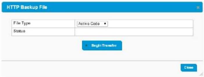
Figure 12-4. TFTP Backup File Page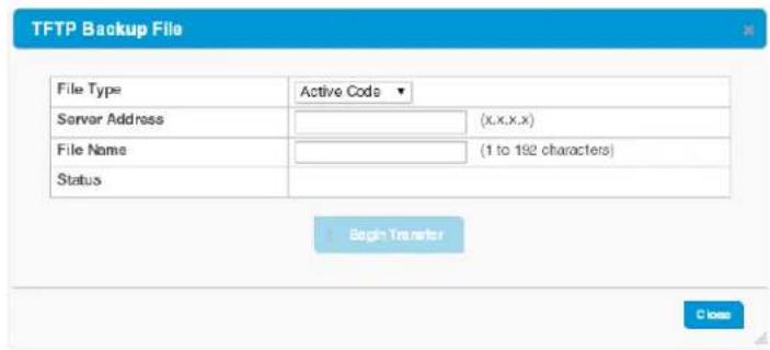
Configure the following settings:
Table 12-2. TFTP and HTTP Backup File Fields
| Field Description | |
| File Type | Select the type of file to back up from the switch to a remote system. You can back up the active or backup image, the system configuration file, the error log in persistent memory (also referred to as the event log), and the buffered log in RAM. |
| Server Address (TFTP only) Enter the IP address of the TFTP server. | |
| File Name | (TFTP only) Enter the path on the server where you want to put the file followed by the name to be applied to the file as it is saved. This can differ from the actual file name on the switch.The path can be 0 to 160 characters and the file name can be 1 to 32 characters.The file name can have ASCII printable characters, excluding the following:\,/, :, *, ?, ",<, >, | |
| Status Status information on the backup process. | |
Click Begin Transfer to begin the backup process. For a TFTP backup, the switch begins the transfer to the specified location. For an HTTP backup, browse to the location on your network where you want to save the file.
Updating Files
To transfer a file from a remote system to the switch using HTTP or TFTP, click the checkbox in either row in the Update column. The HTTP Update or TFTP Update page appears.
To update a file using HTTP, configure the following information and click Begin Transfer.
Figure 12-5. HTTP Update File Page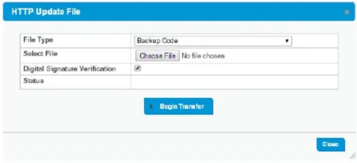
Table 12-3. HTTP Update File Fields
| Field Description | |
| File Type Select the type of file to update:Backup Code—Select this option to transfer a new image to the switch. The code file is stored as the backup image. After updating the backup image, you can use the Dual Image Configuration page to make it the active image upon the next reboot.Note: You cannot directly update the active image.Configuration—Select this option to update the stored configuration file (startup-config). If the file has errors, the update will be stopped.Public Key Image—Select this option to transfer the public key file used for code image validation to the switch.The other file types relate to security settings. For more information, see “Uploading SSL Certificates and Encryption Files” on page 9-5. | |
| Select File | Browse to the location on the network where the new file is located and select it. |
| Digital Signature Verification | For the Backup Code and Configuration file types, you can select this option to have the switch verify the file download with a digital signature. Digital signature verification is applied to backup code only—not to configuration files. |
| Status Status information on the update process. | |
Figure 12-6. TFTP Update File Page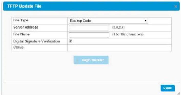
To update a file using TFTP, configure the following information and click Begin Transfer.
Table 12-4. TFTP Update File Fields
| Field Description | |
| File Type See the options in Table 12-3 on page 12-3. | |
| Server Address | Enter the IP address or host name of the TFTP server. |
| File Name | Enter the path on the server where file is located followed by the filename.The path can be 0 to 160 characters and the file name can be 1 to 32 characters. The path and file name are separated by a slash (/).The file name can have ASCII printable characters, excluding the following:\/,: *,?, ",<,>,| |
| Digital Signature Verification | For the active and backup code file types, you can select this option to have the switch verify the file download with a digital signature. |
| Status Status information on the update process. | |
Caution: Do not disturb the browser window while the transfer is in progress.
Dual Image Configuration
The switch can store up to two software images. One image is the active image and the other is the backup image (not actively running on the switch). You can select which image to load during the next boot cycle and add a description for each image on the device.
To display the Dual Image Configuration page, click Maintenance > Dual Image Configuration.
Figure 12-7. Dual Image Configuration Page
Table 12-5. Dual Image Configuration Fields
| Field Description | |
| Image Status | This section lists the current image status information. |
| Image | The type of image, which can be either Active or Backup. |
| Version The software version of the image. | |
| Description | Specify an optional description of the image selected. |
| Next Active | The firmware image that will become active the next time the switch is rebooted. To make the current backup image the active image, select Backup, then reboot the switch. |
Click Apply to save your changes to the switch.

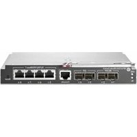
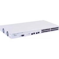


- © COPYRIGHT 2015, 2016 HEWLETT PACKARD ENTERPRISE DEVELOPMENT, L.P. THE INFORMATION CONTAINED HEREIN IS SUBJECT TO CHANGE WITHOUT NOTICE. ALL RIGHTS RESERVED
- PUBLICATION NUMBER
- APPLICABLE PRODUCTS
- TRADEMARK CREDITS
- OPEN SOURCE CODE NOTICE
- DISCLAIMER
- WARRANTY
- PREFACE
- ABOUT THIS DOCUMENT
- AUDIENCE
- ABOUT YOUR SWITCH MANUAL SET
- NOTE
- SUPPORTED FEATURES
- CONTENTS
- GETTING STARTED
- DASHBOARD
- SETUP NETWORK
- SWITCHING FEATURES
- VIRTUAL LAN
- TRUNKS
- LINK LAYER DISCOVERY PROTOCOL (LLDP AND LLDP-MED)
- POWER OVER ETHERNET
- SECURITY
- GREEN FEATURES
- DIAGNOSTICS
- MAINTENANCE PAGES
- CONNECTING THE SWITCH TO A NETWORK
- OPERATING SYSTEM AND BROWSER SUPPORT
- GETTING STARTED WITH THE WEB INTERFACE
- LOGGING ON
- INTERFACE LAYOUT AND FEATURES
- COMMON PAGE ELEMENTS
- SAVING CHANGES
- GRAPHICAL SWITCH
- PORT CONFIGURATION AND SUMMARY
- SYSTEM LEDS
- POWER (GREEN)
- PORT LEDS
- GET CONNECTED
- SYSTEM TIME PAGES
- TIME ZONE SUMMARY
- TIME CONFIGURATION
- TIME ZONE CONFIGURATION
- DAYLIGHT SAVING TIME CONFIGURATION
- PORT CONFIGURATION
- PORT STATUS
- MODIFYING INTERFACE SETTINGS
- PORT SUMMARY STATISTICS
- PORT MIRRORING
- CAUTION
- JUMBO FRAMES
- FLOW CONTROL
- SPANNING TREE
- GLOBAL STP SETTINGS AND PORT STATUS
- PORT STP SETTINGS
- SWITCHING FEATURES SPANNING TREE
- LOOP PROTECTION
- LOOP PROTECTION STATUS
- LOOP PROTECTION CONFIGURATION
- IGMP SNOOPING
- VIEWING VLAN STATUS AND ADDING VLANS
- ADDING VLANS
- CHANGING A VLAN NAME
- CONFIGURING INTERFACES AS VLAN MEMBERS
- VLAN PORT CONFIGURATION
- TRUNK CONFIGURATION
- MODIFYING TRUNK SETTINGS
- TRUNK STATISTICS
- LLDP GLOBAL CONFIGURATION
- LLDP LOCAL DEVICE SUMMARY
- DISPLAYING PORT DETAILS
- LLDP REMOTE DEVICE SUMMARY
- LLDP GLOBAL STATISTICS
- LLDP-MED GLOBAL CONFIGURATION
- LLDP-MED LOCAL DEVICE SUMMARY
- LLDP-MED REMOTE DEVICE SUMMARY
- DISPLAYING REMOTE DEVICE DETAILS
- POE CAPABILITIES
- POE CONFIGURATION
- POE PORT CONFIGURATION
- MODIFYING PORT POE SETTINGS
- VIEWING POE PORT DETAILS
- POE PORT SCHEDULE
- CONFIGURING AN ABSOLUTE TIME PERIOD
- ADDING A PERIODIC TIME PERIOD
- ADVANCED SECURITY CONFIGURATION
- SECURE CONNECTION
- UPLOADING SSL CERTIFICATES AND ENCRYPTION FILES
- GREEN FEATURES CONFIGURATION
- EEE STATUS
- BUFFERED LOG
- FIELD DESCRIPTION
- LOG CONFIGURATION
- PING TEST
- REBOOT SWITCH
- FACTORY DEFAULTS
- SUPPORT FILE
- DIAGNOSTICS LOCATOR
- LOCATOR
- MAC TABLE
- PASSWORD MANAGER
- BACKUP AND UPDATE MANAGER
- BACKING UP FILES
- UPDATING FILES
- DUAL IMAGE CONFIGURATION
Brand : HP
Model : 1820-48G-PoE+
Category : Network switch