FC-54P - Router Kramer - Free user manual and instructions
Find the device manual for free FC-54P Kramer in PDF.

User questions about FC-54P Kramer
0 question about this device. Answer the ones you know or ask your own.
Ask a new question about this device
Download the instructions for your Router in PDF format for free! Find your manual FC-54P - Kramer and take your electronic device back in hand. On this page are published all the documents necessary for the use of your device. FC-54P by Kramer.
USER MANUAL FC-54P Kramer

Scan for full manual
FC-54P Quick Start Guide
This guide helps you install and use your FC-54P for the first time.
Go to www.kramerav.com/downloads/FC-54P to download the latest user manual and check if firmware upgrades are available.
Step 1: Check what's in the box
FC-54P Ethernet Gateway
4 Rubber feet
1 Bracket set
1 Power supply (5V DC)
1 Quick start guide
Step 2: Get to know your FC-54P
flowchart
graph TD
    A["1"] --> B["IR IN"]
    C["2"] --> D["Link"]
    E["3"] --> F["GPIO / RELAY"]
    G["4"] --> H["IR / RS-232"]
    I["5"] --> J["MODE GPIO | RS-232"]
    K["6"] --> L["ON"]
    M["7"] --> N["RELAY | IR"]
    O["Ethernet Gateway"] --> P["FC-54P"]
| # | Feature | Function |
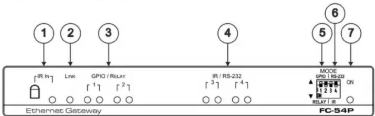
| 1 | IR IN Sensor and LED | Sensor for IR learning, LED lights during activity |
| 2 | LINK LED | Shows the Ethernet link is active |
| 3 | GPIO/RELAY 1/2 LED pairs | Blue LED pair shows the activity status of port 1 and port 2:When set as GPIO, the left LED of the pair indicates active IO-P1 and right LED indicates active IO-P2When set as RELAY, the left LED of the pair indicates active Relay-P1 and right LED indicates active Relay-P2 |
| 4 | IR/RS-232 3/4 LED pairs | Blue LED pair show the activity status of port 3 and port 4:When set as RS-232, the left LED of the pair indicates Tx and right LED indicates RxWhen set as IR, the left LED of the pair indicates IR-P1 Tx and right LED indicates IR-P2 Tx |
| 5 | MODE DIP-switches (Port 1 and Port 2) | Switch up (off) for GPIO, switch down (on) for RelayThe default setting is port 1 GPIO (up) and port 2 Relay (down) |
| 6 | MODE DIP-switches (Port 3 and Port 4) | Switch up for RS-232, switch down for IRThe default setting is port 3 RS-232 (up) and port 4 IR (down) |
| 7 | ON LED | Lights green when the unit is on |
flowchart
graph TD
    A["8"] --> B["1 G P1P2"]
    C["9"] --> D["2 G P1P2"]
    E["10"] --> F["3 G P1P2"]
    G["11"] --> H["4 G P1P2"]
    I["12"] --> J["ID"]
    K["13"] --> L["LAN / POE"]
    M["14"] --> N["5V DC"]
    B --> O["RESET"]
    D --> O
    F --> O
    H --> O
    J --> P["SERVICE"]
| # | Feature | Function |
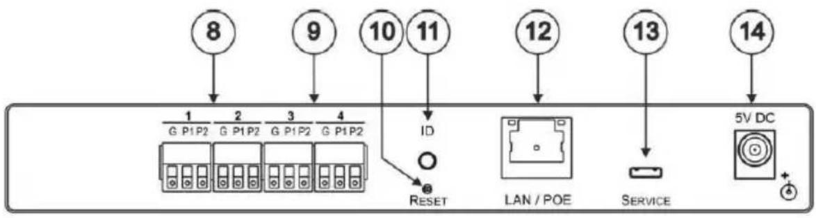
| 8 | Port 1/2 I/O 3-pin Terminal Block | Terminal block ports 1 and 2 connect to two GPIO ports or two Relays each |
| 9 | Port 3/4 I/O 3-pin Terminal Block | Terminal block ports 3 and 4 connect to one bidirectional RS-232 port (or RS-485, port 3 only) or two IR outputs each |
| 10 | RESET Button | Press and hold while cycling the device power to reset to factory default parameters |
| 11 | ID | Press to broadcast ID message for auto-discovery of the device |
| 12 | LAN/POE RJ-45 Connector | Connects to a PoE source (Power over Ethernet) for powering and an IP client or other controller, either directly or via a LAN |
| 13 | SERVICE Mini USB Connector | Connects to a USB power source for powering and to a PC for a local firmware upgrade |
| 14 | 5V DC Connector | For extra power resiliency, connect to the 5V DC power supply, center pin positive. Not needed when the device is supplied power by PoE or a USB power source |
FC-54P Function Table
| Port IO Function | Terminal Block Connections | IO Port Default | TCP Default Port [P1/P2] | Blue Activity LED Pair | Comment | ||
| G | P1 | P2 | |||||
| GPIO | Ground | IO_1 | IO_2 | Digital in x 2 | 5000 | ON when IO ports are active | GPIO Analog in & Digital out via Web |
| Relay | Common | NO_1 | NO_2 | Normally Open x 2 | 5000 | ON when Relay ports are active | |
| RS-232 | Ground | Rx | Tx | 9600,B,N,1 | 5001/2 | Flashes when port is transmitting & receiving data | Other serial configurations via Web, including RS-485 for Port 3 |
| IR | Ground | IR_1 | IR_2 | 5000 | ON when ports are transmitting IR data | ||
Key:
P1 / P2 - Port 1 / Port 2
ID_1/IO_2-GPIO Port 1/GPIO Port 2
NO_3/NO_2 - Normally open Port 1 / Normally open Port 2
Tx - Transmit, Rx - Receive; 9600, 8, N, 1 - 9600 baud, 8 - bits, no parity, 1 stop bit
IR_1/IR_2-IR Port 1 / IR Port 2
Step 3: Install the FC-54P
You can mount this Kramer MegaTOOLS™ next to a USB power source behind an AV device, in the ceiling, on a desk top, wall or similar area. Install FC-54P using one of the following methods:
- Attach the rubber feet and place the unit on a flat surface.
- Fasten a bracket (included) on each side of the unit and attach it to a flat surface. For more information go to www.kramerav.com/downloads/FC-54P.
- Mount the unit in a rack using an optional RK-T2B rack adapter.
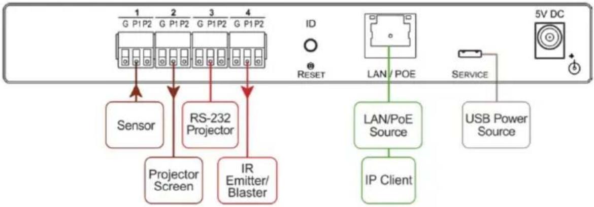
Step 4: Connect the inputs and outputs
Always switch OFF the power on each device before connecting it to your FC-54P. For best results, we recommend that you always use Kramer high-performance cables to connect controlled equipment to the FC-54P.
flowchart
graph TD
    A["Sensor"] --> B["Projector Screen"]
    B --> C["RS-232 Projector"]
    C --> D["IR Emitter/Blaster"]
    D --> E["IP Client"]
    E --> F["LAN/PoE Source"]
    F --> G["LAN/POE"]
    G --> H["Service"]
    H --> I["USB Power Source"]
    style A fill:#f9f,stroke:#333
    style B fill:#f9f,stroke:#333
    style C fill:#f9f,stroke:#333
    style D fill:#f9f,stroke:#333
    style E fill:#f9f,stroke:#333
    style F fill:#ccf,stroke:#333
    style G fill:#ccf,stroke:#333
    style H fill:#ccf,stroke:#333
    style I fill:#ccf,stroke:#333
Step 5: Connect the power
Connect the PoE or a USB power source and/or a 5V DC power adapter to the FC-54P and plug it into the mains electricity.
Safety Instructions

Caution: There are no operator serviceable parts inside the unit.
Warning: Use only the Kramer Electronics power supply that is provided with the unit.
Warning: Disconnect the power and unplug the unit from the wall before installing.
See www.KramerAV.com for updated safety information.
Step 6: Configure and operate the FC-54P
Note: The FC-54P is shipped from the factory with DHCP enabled and a random IP address. To connect the FC-54P on first installation, you must identify what IP address has been automatically assigned to the FC-54P. To discover the IP address of FC-54P, use K-LAN Configurator, available for download from our website at www.kramerav.com.
To reset the device to its factory default settings:
- Turn off the power to the device.
- Press and hold the Reset button on the rear panel.
- Turn on the power to the device while holding down the Reset button for a few seconds.
- Release the button.
The device is reset to the factory default settings.
To browse the FC-54P Web UI (User Interface) on taking the device out of the box:
Use the default host name: FC-54P-xxxx, where xxxx are the last four digits of the serial number of the device.
To configure and operate the FC-54P
- Using the device Web UI, configure the control gateway:
- Set DHCP or assign a static IP address
- Associate IP port(s) with the relevant port(s)
- Configure the relevant port parameters
- Configure IP client connection port(s) on a Kramer control or any other control software application.
- Set the control application to use the control gateway ports for sending and receiving control communication over the IP connections.
Contents
1 Introduction 1
2 Getting Started 2
2.1 Achieving the Best Performance 2
2.2 Safety Instructions 2
2.3 Recycling Kramer Products 3
3 Overview 4
4 Defining the FC-54P Ethernet Gateway - Serial/IR/GPIO/Relay 6
5 Performing Initial Configuration 8
5.1 Configuring the FC-54P Ethernet Gateway - Serial/IR/GPIO/Relay 8
5.2 Setting Up an Ethernet Connection on the PC 10
6 Connecting the FC-54P 11
6.1 Connecting via Ethernet 12
7 Remote Operation via the Web UI 17
7.1 Browsing the Web UI 17
7.2 Displaying Connected Clients 20
7.3 Setting Device Name and Time Functions 20
7.4 Setting Communication Parameters 22
7.5 Setting Serial Port Parameters 22
7.6 Setting GPIO Port Parameters 25
7.7 Setting Relay Port Status 29
7.8 Configuring IR Command Learning 30
7.9 Activating Security 32
7.10 Using the Logs Page 34
7.11 Kramer Information 35
8 Using FC-54P Operations 36
8.1 Using IR Learning 36
8.2 Resetting to the Factory Default Settings 37
8.3 Upgrading the Firmware 37
9 Technical Specifications 38
9.1 Data Handling Performance 39
9.2 Example Bandwidth Calculation 39
10 Default Parameters 40
11 Kramer Protocol 3000 41
11.1 Kramer Protocol 3000 – Syntax 42
11.2 Kramer Protocol 3000 – Command List 45
11.3 Kramer Protocol 3000 – Detailed Commands 46
Figures
Figure 1: FC-54P Controlling Devices Remotely Using K-Touch 3.0 over a LAN 5
Figure 2: FC-54P Ethernet Gateway - Serial/IR/GPIO/Relay 6
Figure 3: Connecting the FC-54P for Initial Configuration 8
Figure 4: Configuring a Remote Connection 10
Figure 5: Connecting the FC-54P Ethernet Gateway - Serial/IR/GPIO/Relay 11
Figure 6: Terminal Block Connections 12
Figure 7: Local Area Connection Properties Window 13
Figure 8: Internet Protocol Version 4 Properties Window 14
Figure 9: Internet Protocol Version 6 Properties Window 14
Figure 10: Internet Protocol Properties Window 15
Figure 11: General Info Page 18
Figure 12: Connected Clients Page 20
Figure 13: Device Settings Page 21
Figure 14: Communication Page 22
Figure 15: Serial Port Settings Page 23
Figure 16: Serial Port Settings Page – RS-485 24
Figure 17: Serial Port Settings Page – No Serial Ports Configured 24
Figure 18: GPIO Port Settings Page 25
Figure 19: GPIO Port Settings Page – No GPIO Ports Configured 26
Figure 20: GPIO Port Settings Page Digital IN 26
Figure 21: GPIO Port Settings Page Digital OUT 27
Figure 22: Digital Out Selection Warning Popup 27
Figure 23: GPIO Port Settings Page Analog IN 28
Figure 24: Relay Port Settings Page 29
Figure 25: IR Command Learner Page 31
Figure 26: Security Page 32
Figure 27: Security Confirmation Popup 32
Figure 28: Authentication Required Popup 33
Figure 29: Security Activated Page 33
Figure 30: Logs Page 34
Figure 31: About Us Page 35
1 Introduction
Welcome to Kramer Electronics! Since 1981, Kramer Electronics has been providing a world of unique, creative, and affordable solutions to the vast range of problems that confront video, audio, presentation, and broadcasting professionals on a daily basis. In recent years, we have redesigned and upgraded most of our line, making the best even better!
Our 1,000-plus different models now appear in 14 groups that are clearly defined by function: GROUP 1: Distribution Amplifiers; GROUP 2: Switchers and Routers; GROUP 3: Control Systems; GROUP 4: Format/Standards Converters; GROUP 5: Range Extenders and Repeaters; GROUP 6: Specialty AV Products; GROUP 7: Scan Converters and Scalers; GROUP 8: Cables and Connectors; GROUP 9: Room Connectivity; GROUP 10: Accessories and Rack Adapters; GROUP 11: Sierra Video Products; GROUP 12: Digital Signage; GROUP 13: Audio; and GROUP 14: Collaboration.
Congratulations on purchasing your Kramer FC-54P Ethernet Gateway - Serial/IR/GPIO/Relay that is ideal for use in the following applications:
- Remote IP control of RS-232, IR, GPIO, and relay-controllable devices by any control software app
• K-Touch multi-clients IP room control
• LAN-based expansion of K-Config control system
2 Getting Started
We recommend that you:
- Unpack the equipment carefully and save the original box and packaging materials for possible future shipment
• Review the contents of this user manual

Go to www.kramerav.com/downloads/FC-54P to check for up-to-date user manuals, application programs, and to check if firmware upgrades are available (where appropriate).
2.1 Achieving the Best Performance
To achieve the best performance:
- For optimum range and performance, use the recommended Kramer cables available at www.kramerav.com/product/FC-54P
- Do not secure the cables in tight bundles or roll the slack into tight coils
- Avoid interference from neighbouring electrical appliances that may adversely influence signal quality
• Position your FC-54P away from moisture, excessive sunlight and dust

This equipment is to be used only inside a building. It may only be connected to other equipment that is installed inside a building.
2.2 Safety Instructions

Caution: There are no operator serviceable parts inside the unit
Warning: Use only the Kramer Electronics power supply that is provided with the unit
Warning: Disconnect the power and unplug the unit from the wall before installing
2.3 Recycling Kramer Products
The Waste Electrical and Electronic Equipment (WEEE) Directive 2002/96/EC aims to reduce the amount of WEEE sent for disposal to landfill or incineration by requiring it to be collected and recycled. To comply with the WEEE Directive, Kramer Electronics has made arrangements with the European Advanced Recycling Network (EARN) and will cover any costs of treatment, recycling and recovery of waste Kramer Electronics branded equipment on arrival at the EARN facility. For details of Kramer's recycling arrangements in your particular country go to our recycling pages at www.kramerav.com/support/recycling/.
3 Overview
FC-54P is a multi-function PoE control gateway, capable of plug and play deployment over an existing Ethernet LAN for GPI/O, relay, IR and serial control of customer devices. Multiple control clients can be IP-connected to the FC-54P control gateway for concurrent control of devices such as projectors, displays, DVD players, lights, shades and screens.
The FC-54P features:
- Dual-Function I/O Ports - Remote IP-based control of any device connected to the control gateway I/O ports, with selectable port configuration to bidirectional RS-232/RS-485, IR, GPI/O or relay control. Each port adapts to any room control device by setting a DIP-switch.
- Multiple IP Connected Clients - Remotely connects over a customer Ethernet network that concurrently controls devices connected to the control gateway universal I/O ports.
-
Easy & Reliable Installation:
-
Single PoE cable for powering and connectivity, Plug and Play IP installation with dynamic (DHCP) address resolution and auto device discovery over existing LAN.
- Highly-resilient powering with multiple power options — USB, Power over Ethernet per IEEE 802.3af standard, and/or PSU (included).
- Compact, designed for piggy-back installation, such as behind a TV or display with the ability to draw power from device USB port and Ethernet connectivity.
- Remote Management - Built-in web UI for remote browser-based management and support, by multiple IP-clients over existing LAN. Easy firmware upgrades, either remotely via existing LAN, or locally via device USB port.
- Size - MegaTOOLS™ - Mount 2 units side-by-side in a 1U rack space with the optional RK-T2B rack adapter.
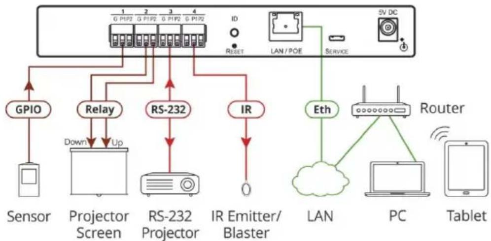
flowchart
graph TD
    A["Sensor"] --> B["Sensor"]
    B --> C["Projector Screen"]
    C --> D["RS-232 Projector"]
    D --> E["IR Emitter/Blaster"]
    E --> F["LAN"]
    F --> G["Router"]
    G --> H["PC"]
    H --> I["Tablet"]
    J["GPIO"] --> C
    K["Relay"] --> C
    L["Down"] --> C
    M["Up"] --> C
    N["RS-232"] --> D
    O["ID"] --> P["RESET"]
    Q["SV DC"] --> R["Service"]
    S["ETH"] --> T["Cloud"]
    U["Router"] --> V["PC"]
    W["Sensor"] --> X["Sensor"]
Figure 1: FC-54P Controlling Devices Remotely Using K-Touch 3.0 over a LAN
For example, using Kramer K-Touch control software you can design advanced room-control and automation systems that can be operated from iOS or Android touch devices. K-Touch can be used to perform device discovery over the network as the FC-54P is set to be a DHCP client by default.
You can use the Kramer LAN Configurator software to discover devices that are attached to the network, including the FC-54P.
4 Defining the FC-54P Ethernet Gateway - Serial/IR/GPIO/Relay
This section defines the FC-54P.
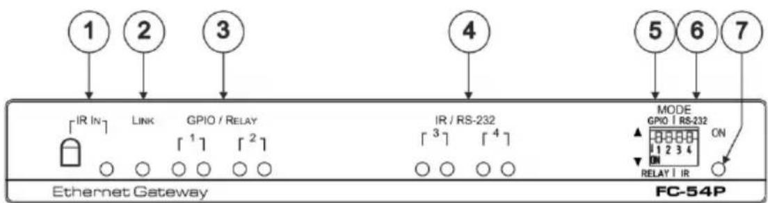
Figure 2: FC-54P Ethernet Gateway - Serial/IR/GPIO/Relay
| # | Feature | Function |
| 1 | IR IN Sensor and LED | Sensor for IR learning, LED lights during activity |
| 2 | LINK LED | Shows the Ethernet link is active |
| 3 | GPIO/RELAY 1/2 LED pairs | Blue LED pair shows the activity status of port 1 and port 2:When set as GPIO, the left LED of the pair indicates active IO-P1 and right LED indicates active IO-P2When set as RELAY, the left LED of the pair indicates active Relay-P1 and right LED indicates active Relay-P2 |
| 4 | IR/RS-232 3/4 LED pairs | Blue LED pair shows the activity status of port 3 and port 4:When set as RS-232, the left LED of the pair indicates Tx and right LED indicates RxWhen set as IR, the left LED of the pair indicates IR-P1 Tx and right LED indicates IR-P2 Tx |
| 5 | MODE DIP-switches (Port 1 and Port 2) | Switch up (off) for GPIO, switch down (on) for RelayThe default setting is port 1 GPIO (up) and port 2 Relay (down) |
| 6 | MODE DIP-switches (Port 3 and Port 4) | Switch up for RS-232, switch down for IRThe default setting is port 3 RS-232 (up) and port 4 IR (down) |
| 7 | ON LED | Lights green when the unit is on |
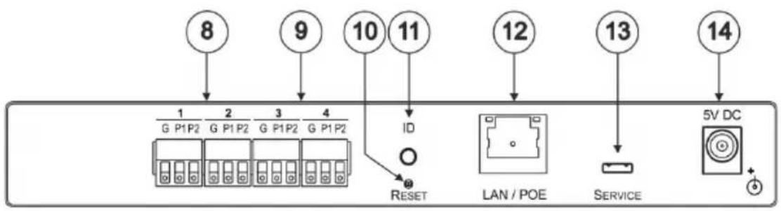
| # | Feature | Function |
| 8 | Port 1/2 I/O 3-pin Terminal Block | Terminal block ports 1 and 2 connect to two GPIO ports or two Relays each |
| 9 Port | 3/4 I/O 3-pin Terminal Block | Terminal block ports 3 and 4 connect to one bidirectional RS-232 port (or RS-485, port 3 only) or two IR outputs each |
| 10 | RESET Button | Press and hold while cycling the device power to reset to factory default parameters |
| 11 | ID | Press to broadcast ID message for auto-discovery of the device |
| 12 | LAN/POE RJ-45 Connector | Connects to a PoE source (Power over Ethernet) for powering and an IP client or other controller, either directly or via a LAN |
| 13 | SERVICE Mini USB Connector | Connects to a USB power source for powering and to a PC for a local firmware upgrade |
| 14 | 5V DC Connector | For extra power resiliency, connect to the 5V DC power supply, center pin positive.Not needed when the device is supplied power by PoE or a USB power source |
FC-54P Function Table
| Port IO Function | Terminal Block Connections | IO Port Default | TCP Default Port [P1/P2] | Blue Activity LED Pair | Comment | ||
| G P1 P2 | |||||||
| GPIO | Ground IO 1 IO 2 | Digital In x 2 | 5000 | ON when IO ports are active | GPIO Analog in & Digital out via Web | ||
| Relay | Common NO 1 NO 2 | Normally Open x 2 | 5000 | ON when Relay ports are active | |||
| RS-232/RS-485 | Ground | Rx | Tx | 9600,8,N,1 | 5001/2 | Flashes when port is transmitting & receiving data | Other serial configurations via Web, including RS-485 for Port 3 |
| IR | Ground | IR1 | IR2 | 5000 | ON when ports are transmitting IR data | ||
Key:
P1 / P2 - Port 1 / Port 2
IO_1 / IO_2 - GPIO Port 1 / GPIO Port 2
NO_1/NO_2 – Normally open Port 1 / Normally open Port 2
Tx - Transmit, Rx - Receive; 9600, 8, N, 1 - 9600 baud, 8-bits, no parity, 1 stop bit
IR_1/IR_2-IR Port 1 / IR Port 2
5 Performing Initial Configuration
This chapter provides an overview of the initial configuration of the FC-54P and comprises:
- Configuring the FC-54P (see Section 5.1)
- Configuring an Ethernet connection on the PC (see Section 5.2)
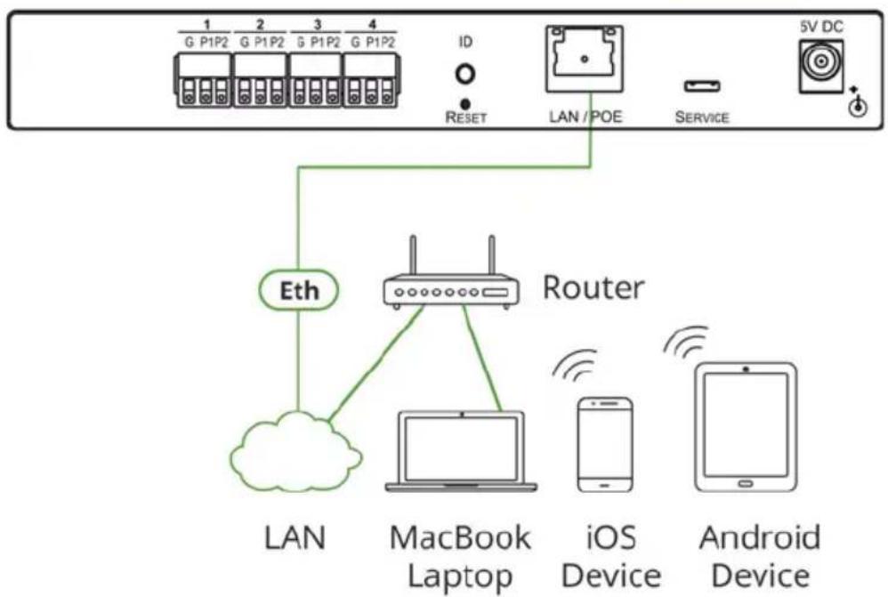
flowchart
graph TD
    A["1 G P1P2"] --> B["2 G P1P2"]
    B --> C["3 G P1P2"]
    C --> D["4 G P1P2"]
    D --> E["ID RESET"]
    E --> F["LAN / POE"]
    F --> G["SERVICE"]
    G --> H["5V DC +"]
    I["ETH"] --> J["Router"]
    K["LAN"] --> J
    L["MacBook Laptop"] --> J
    M["iOS Device"] --> J
    N["Android Device"] --> J
Figure 3: Connecting the FC-54P for Initial Configuration
5.1 Configuring the FC-54P Ethernet Gateway - Serial/IR/GPIO/Relay
Note: The FC-54P is shipped from the factory with DHCP enabled (off by default) and a random IP address. To connect the FC-54P on first installation, you must identify the IP address that was automatically assigned to the FC-54P. To discover the IP address of FC-54P, use K-LAN Configurator, available for download from our website at www.kramerav.com.
To browse the FC-54P Web UI on taking the device out of the box:
Use the default host name: FC-54P-xxxx, where xxxx are the last four digits of the serial number of the device.
To configure the FC-54P:
- Connect the Ethernet port on the rear panel of the FC-54P to a PC, either directly or via a LAN, (see Section 6.1).
- Using a Web browser and the relevant IP address or host name (see Section 9.1), browse the General Info home page (see Figure 11).
- Click Device Settings to browse to the Device Settings page, (see Figure 13).
- Enter the time and date manually, or enter the Time server address for automatic time and date synchronization.
- Click Save Changes.
- Click Communication to browse to the Communication page, (see Figure 14).
- Enter the IP address, mask and gateway for static IP addressing and click Set. We recommend that you set a meaningful host name. Note: If you have changed the IP address from the default setting, you must reload the General Info home page again using the new IP address.
- Click GPIO Port Settings to browse to the GPIO Port Settings page, (see Section 7.5). Here you can configure digital in, digital out and analog in port parameters.
- Set the trigger type, voltage levels and status of each port.
- Click Save Changes.
- Click Relay Port Settings to browse to the Relay Port Settings page, (see Section 7.7). Here you can set the relays on or off.
- If required, click Security (see Section 7.9) to browse to the Security page.
-
Click ON to activate security. The user name and password credentials popup appears.
-
Enter the required user name and password. (The default user name is Admin and the password is Admin).
5.2 Setting Up an Ethernet Connection on the PC
If the control application can directly connect to the Ethernet driver, select the host IP address and port number according to your FC-54P configuration, as illustrated in Figure 4.
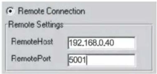
Figure 4: Configuring a Remote Connection
6 Connecting the FC-54P

Always switch off the power to each device before connecting it to your FC-54P. After connecting your FC-54P, connect its power and then switch on the power to each device.
flowchart
graph TD
    A["Sensor"] --> B["Sensor"]
    B --> C["Projector Screen"]
    C --> D["RS-232 Projector"]
    D --> E["IR Emitter/Blaster"]
    E --> F["LAN/PoE Source"]
    F --> G["Optional USB Power Source"]
    G --> H["Power"]
    C --> I["Relay"]
    I --> J["Down"]
    J --> K["Up"]
    K --> L["RS-232"]
    L --> M["IR"]
    M --> N["IR"]
    N --> O["IR"]
    O --> P["Relay"]
    P --> Q["Relay"]
    Q --> R["Sensor"]
    L --> S["Relay"]
    S --> T["Sensor"]
    style A fill:#f9f,stroke:#333
    style B fill:#ccf,stroke:#333
    style C fill:#cfc,stroke:#333
    style D fill:#fcc,stroke:#333
    style E fill:#cff,stroke:#333
    style F fill:#ffc,stroke:#333
    style G fill:#fcc,stroke:#333
    style H fill:#cfc,stroke:#333
    style I fill:#cfc,stroke:#333
    style J fill:#cfc,stroke:#333
    style K fill:#cfc,stroke:#333
    style L fill:#cfc,stroke:#333
    style M fill:#cfc,stroke:#333
    style N fill:#cfc,stroke:#333
    style O fill:#cfc,stroke:#333
    style P fill:#cfc,stroke:#333
    style Q fill:#cfc,stroke:#333
    style R fill:#cfc,stroke:#333
    style S fill:#cfc,stroke:#333
    style T fill:#cfc,stroke:#333
    style U fill:#cfc,stroke:#333
    style V fill:#cfc,stroke:#333
    style W fill:#cfc,stroke:#333
    style X fill:#cfc,stroke:#333
    style Y fill:#cfc,stroke:#333
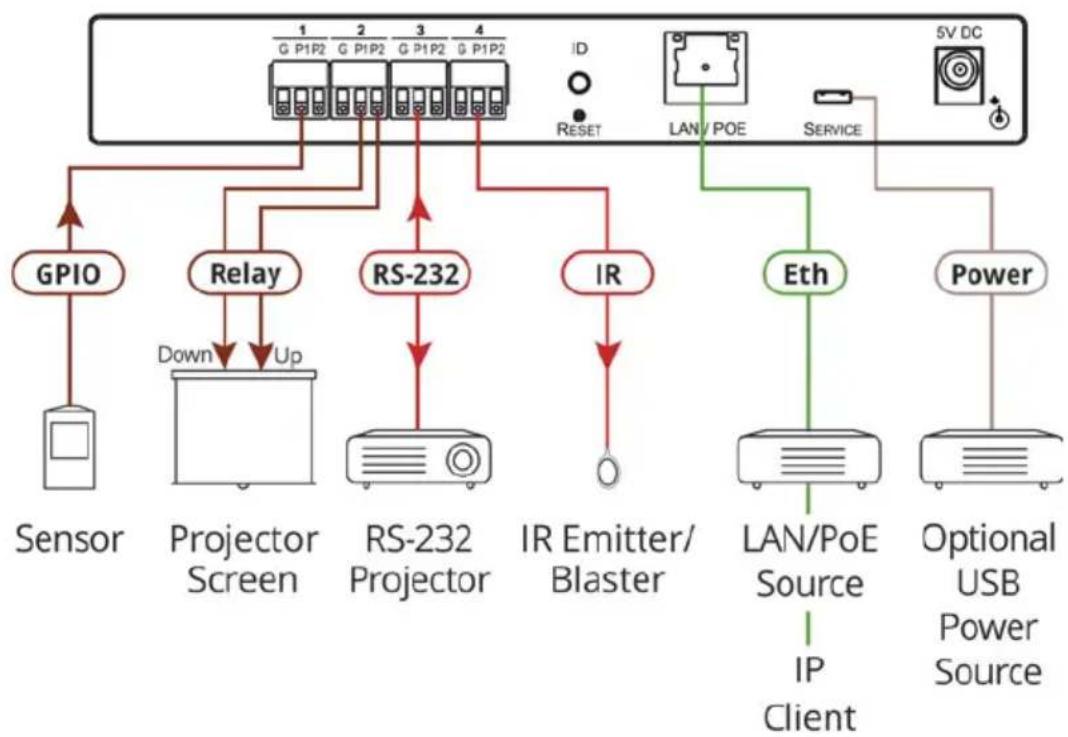
Figure 5: Connecting the FC-54P Ethernet Gateway - Serial/IR/GPIO/Relay
To connect the FC-54P as illustrated in the example in Figure 5:
- Connect the device to a LAN or PC via the RJ-45 Ethernet connector.
- Set DIP-switch 1 up to select GPIO.
Connect an input or output device, (for example, a sensor) to terminal block 1, according to the connections shown in Figure 6.
- Set DIP-switch 2 down to select relay.
Connect a relay-controlled device, (for example, a projection screen) to terminal block 2, according to the connections shown in Figure 6.
- Set DIP-switch 3 up to select RS-232.
Connect an RS-232-controlled device, (for example, a projector) to terminal block 3, according to the connections shown in Figure 6.
- Set DIP-switch 4 down to select IR.
Connect an IR device (for example, an emitter/blaster) to terminal block 4, according to the connections shown in Figure 6.
| Port IO Function | Terminal Block Connections | ||
| G | P1 | P2 | |
| GPIO | Ground IO | _1 IO | _2 |
| Relay | Common | NO _1 NO | _2 |
| RS-232/RS-485 | Ground Rx | Tx | |
| IR | Ground IR | _1 IR | _2 |
Figure 6: Terminal Block Connections
- If the FC-54P does not receive power from a PoE provider or a USB power connection, connect the device to the power supply and connect the power adapter to the mains electricity (not shown in Figure 5).
Note: Changing the DIP-switches resets the ports to their default state: GPIO resets to its low logic state and the relay resets to its open state.
6.1 Connecting via Ethernet
You can connect to the FC-54P via Ethernet using either of the following methods:
- Directly to the PC using a crossover cable (see Section 6.1.1)
- Via a network hub, switch, or router, using a straight-through cable (see Section 6.1.2)
Note: If you want to connect via a router and your IT system is based on IPv6, speak to your IT department for specific installation instructions.
6.1.1 Connecting the Ethernet Port Directly to a PC
You can connect the Ethernet port of the FC-54P directly to the Ethernet port on your PC using a crossover cable with RJ-45 connectors.

This type of connection is recommended for identifying the FC-54P with the factory configured default IP address.
After connecting to the Ethernet port, configure your PC as follows:
- Click Start > Control Panel > Network and Sharing Center.
- Click Change Adapter Settings.
- Highlight the network adapter you want to use to connect to the device and click Change settings of this connection.
The Local Area Connection Properties window for the selected network adapter appears as shown in Figure 7.
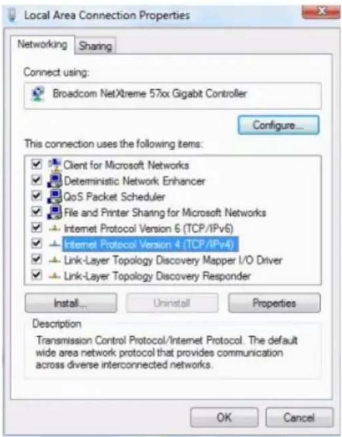
Figure 7: Local Area Connection Properties Window
- Highlight Internet Protocol Version 4 (TCP/IPv4) and click Properties.
The Internet Protocol Properties window relevant to your IT system appears as shown in Figure 8 or Figure 9.
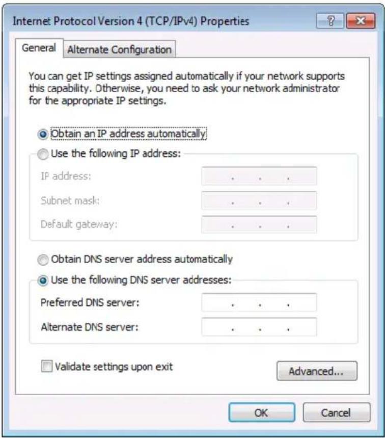
Figure 8: Internet Protocol Version 4 Properties Window
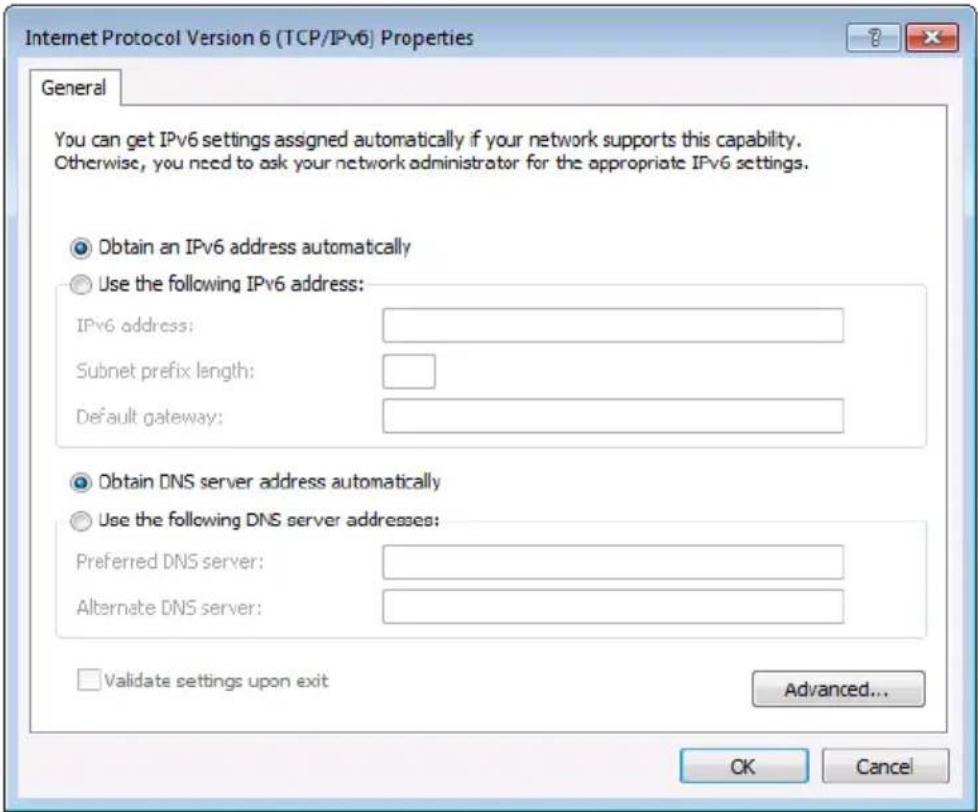
Figure 9: Internet Protocol Version 6 Properties Window
- Select Use the following IP Address for static IP addressing and fill in the details as shown in Figure 10.
For TCP/IPv4 you can use any IP address in the range 192.168.1.1 to 192.168.1.255 (excluding 192.168.1.39) that is provided by your IT department.
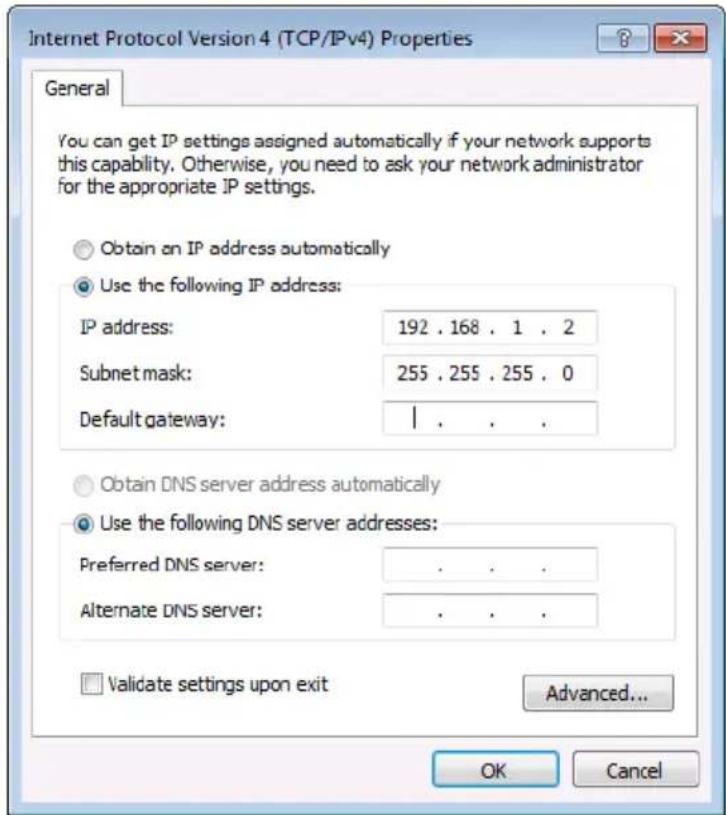
Figure 10: Internet Protocol Properties Window
- Click OK.
- Click Close.
6.1.2 Connecting the Ethernet Port via a Network Hub or Switch
You can connect the Ethernet port of the FC-54P to the Ethernet port on a network hub or switch using a straight-through cable with RJ-45 connectors.
6.1.3 Connecting the GPIO Ports on the FC-54P to a Device
To connect the GPIO port on the FC-54P to a device:
- Connect the G pin on the GPIO port to the ground connection on the device
- Connect the S pin on the GPIO port to the signal/positive connection on the device
- Set the DIP-switch for the port UP (Off)
6.1.4 Connecting the Relays on the FC-54P to a Device
To connect the relay port on the FC-54P to a device:
- Connect the C pin on the relay port to the ground connection on the device
- Connect the NO pin on the relay port to the signal/positive connection on the device
- Set the DIP-switch for the port DOWN (On) for Relay
6.1.5 Connecting the RS-232/RS-485 Port on the FC-54P to a Device
To connect to the FC-54P via RS-232/RS-485:
- Connect the RS-232, 3-pin, terminal block connectors on the rear panel of the FC-54P using 3-wire cable (pin TX to pin 2, RX to pin 3, and G to pin 5) to the RS-232 9-pin D-sub port on the devices to be controlled

To set the port to RS-485, use the Serial Port Settings UI page in Section 7.5
6.1.6 Connecting the IR Port on the FC-54P to a Device
To connect to the FC-54P via IR:
- Connect an IR blaster to one of the IR Outputs and place it within 4m to 8m (13 to 26ft) and in line-of-sight of the device to be controlled
—OR—
- Connect an IR emitter cable to one of the IR outputs and stick the emitter to the IR sensor on the device to be controlled
7 Remote Operation via the Web UI
The embedded Web UI can be used to remotely operate the FC-54P using a Web browser and an Ethernet connection.
Before attempting to connect:
- Perform the initial configuration in Section 5.1 and connecting via Ethernet in Section 6.1
- Ensure that your browser is supported (see Section 9)
7.1 Browsing the Web UI
To browse the Web UI:
- Open your Internet browser. Type the IP address or host name of the device (see Section 5.1) in the Address bar of your browser.

http://192.168.1.39

The Loading page appears followed shortly by the General Info page shown in Figure 11.
The General Info page displays the following:
- Model Name
- Firmware version
• Device serial number - Web UI version
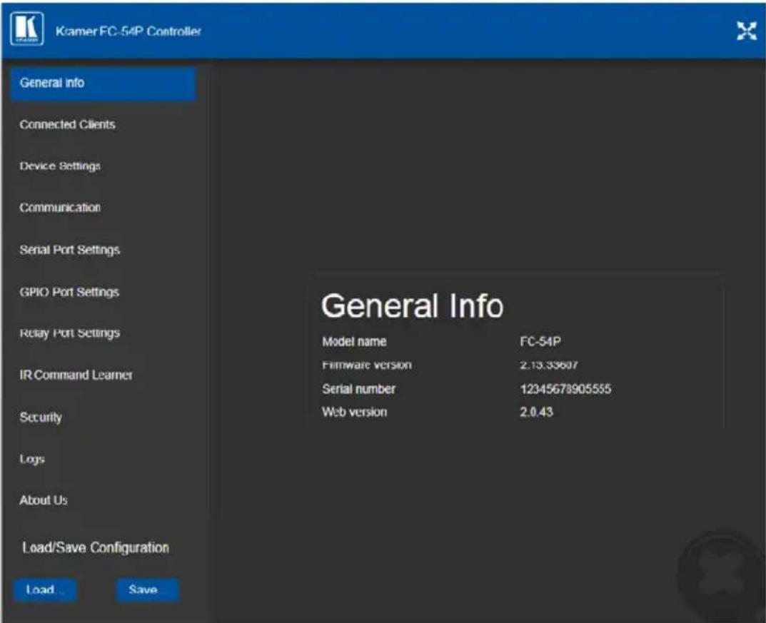
Figure 11: General Info Page
Loading and Saving Configurations
Loading and saving configurations is used for duplicating multiple device definitions for easy system configuration. The configurations are loaded and saved to a local PC. Load and save is performed using the buttons at the bottom left-hand side of the screen for all pages displayed.
To load a configuration:
- Click Load.
The Explorer window opens.
-
Browse to the required file.
-
Select the required file and click Open.
The device is configured according to the saved preset.
To save the current configuration:
- Configure the device as required.
- Click Save.
The Save File window opens.
- Browse to the required location to which to save the file.
- Enter the required name for the saved preset.
- Click OK.
The current configuration is saved.
Note: When using Chrome, the file is automatically saved in the Downloads folder.
The following parameters are saved to the configuration file:
| UI Page | Parameter |
| Device Settings (Figure 13) | Model NameTime ZoneDaylight Savings Time modeUse Time Server modeTime Server AddressSync Every Day time |
| Communication (Figure 14) | UDP PortTCP Port |
| Serial Port Setting (Figure 15) | Serial PortProtocolIP PortTCP Keep AliveParityData BitsBaud RateStop BitsSend Replies to New Client by Default |
| GPIO Port Settings (Figure 18) | GPIO PortTrigger TypePull-up ResistorThreshold VDC Range MinThreshold VDC Range MaxMaximum Reported Steps |
7.2 Displaying Connected Clients
The Connected Clients page (Figure 12) allows you to view the following details of any client devices connected via Ethernet to the FC-54P:
- IP address
• The port it is connected to
• Method of connection
• Whether or not Send Replies is enabled for the port
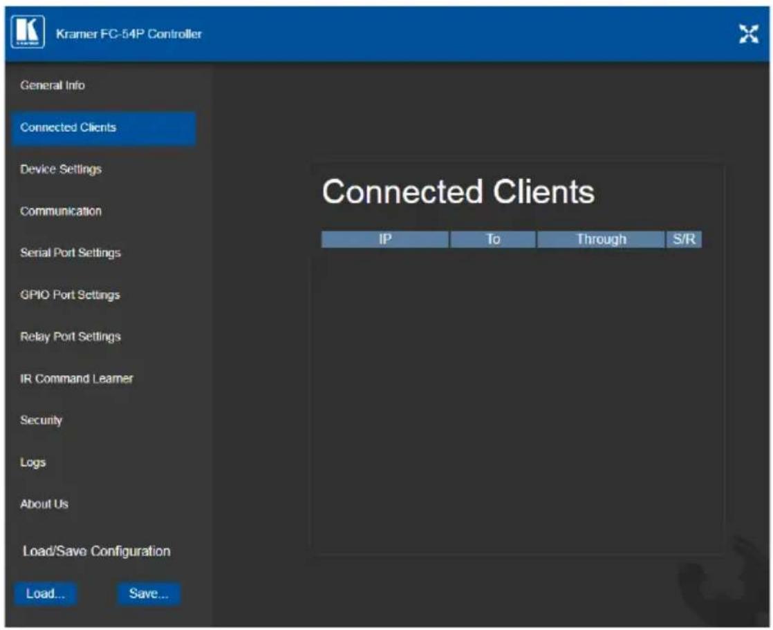
Figure 12: Connected Clients Page
7.3 Setting Device Name and Time Functions
The Device Settings page (Figure 13) allows you to view the model name and time server status. You can also modify the following fields:
- Device name
• Device time, date, and time zone
- Use a timeserver to set the time and date automatically using a (if the device is connected to the Internet), including the Time Zone and daylight savings time
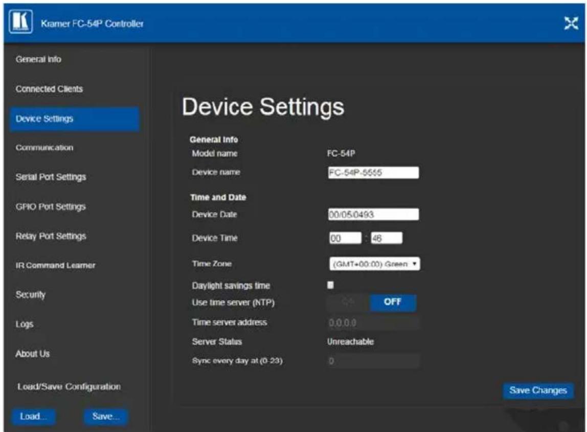
Figure 13: Device Settings Page
The FC-54P has a built-in clock that can synchronize with a Time Server if required.
To enable Time Server synchronization:
- Browse to the Device Settings page by clicking Device Settings. The Device Settings page is displayed as shown in Figure 13.
- Click the Use Time Server ON button.
- Enter the IP address of the Time Server.
- Enter the time of day at which the FC-54P should synchronize with the Time Server.
- Click Save Changes.
7.4 Setting Communication Parameters
The communication page allows you to:
• Turn DHCP for the device on and off
• Edit the IP settings for static IP addressing
Note: The default IP address setting for the device is DHCP.
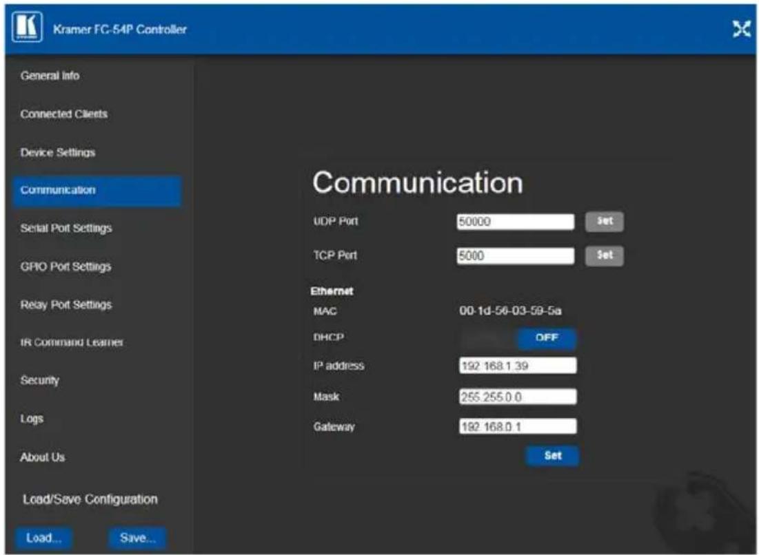
Figure 14: Communication Page
After modifying any of the IP settings, click Set to save the changes.
7.5 Setting Serial Port Parameters
The Serial Port Settings page allows you to:
- Set the following Ethernet parameters for each Ethernet port:
- Select TCP or UDP
- IP port label
- TCP keep alive time – 0-3600sec (default 60sec) internal time, after which detected idle connection is disconnected
- Set the following serial parameters for each serial port:
• Device serial mode – RS-232 or RS-485 with or without termination
- Parity
Data bits
- Baud rate
- Stop bits
- Select whether or not to send replies on the port to the new client
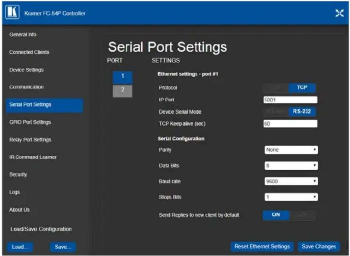
Figure 15: Serial Port Settings Page
To select device serial mode RS-485:
- Click RS-485 and click to enable or disable termination.
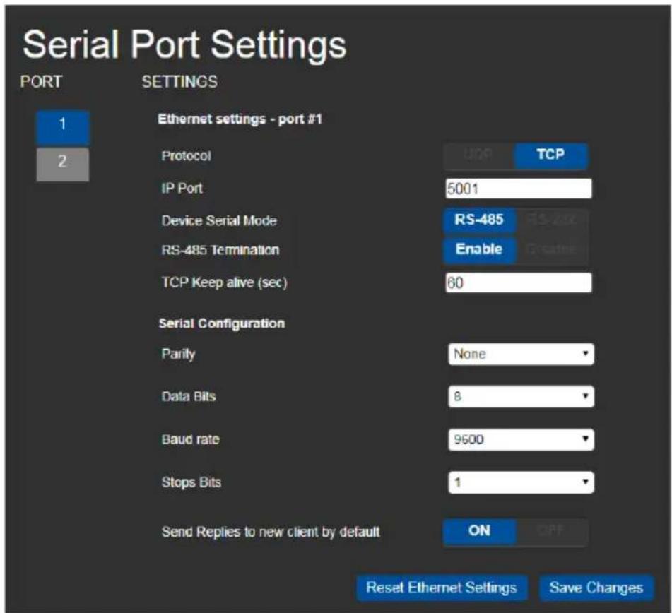
Figure 16: Serial Port Settings Page – RS-485

Note: When DIP-switches 3 and 4 are set down to IR, serial ports 1 and 2 are grayed out and the following serial port settings screen appears:
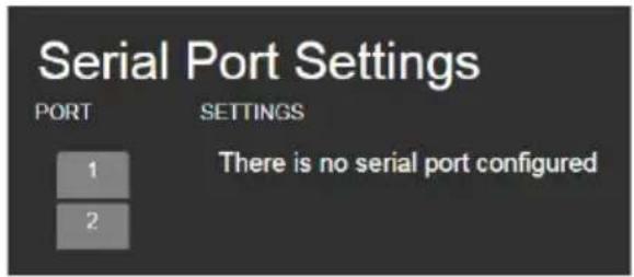
Figure 17: Serial Port Settings Page – No Serial Ports Configured
7.6 Setting GPIO Port Parameters
GPIO ports are used to connect and control hardware devices to the FC-54P such as sensors, switches and LED indicators that input and output digital signals and input analog signals.
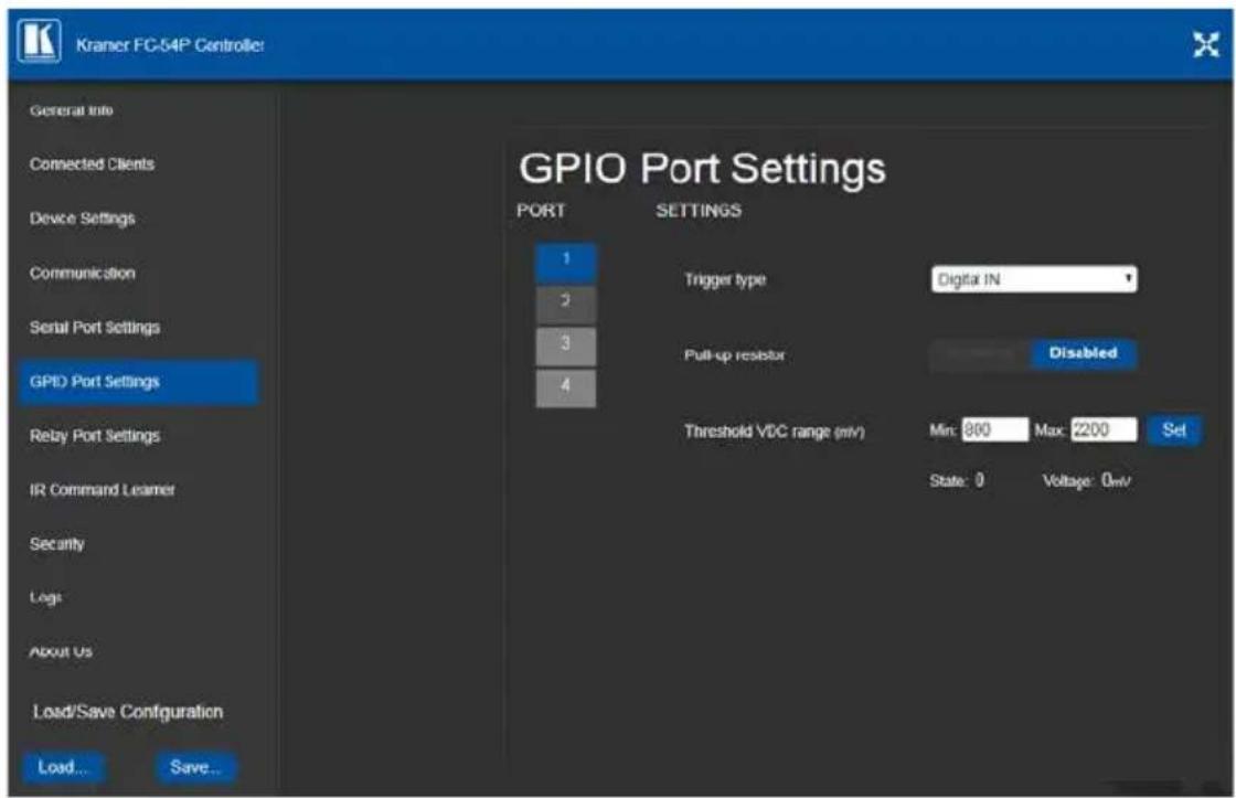
Figure 18: GPIO Port Settings Page
The GPIO Port Setting page allows you to configure the following for each GPIO port:
- Trigger type—digital input, digital output, or analog input
- Enable and disable the pull-up resistor for the digital input and output
- Set the threshold trigger voltage range for the digital input
- Set the current status for the digital output signal to high or low
- Set the maximum number of reported steps for the analog input
- Read—Press to read the state of the port (displayed according to the page)
- State—Displays the digital state of the port, either 1 (high) or 0 (low) (displayed according to the page)
GPIO sub-ports are displayed according to their DIP-switch settings.
Note: The default parameter settings change depending on which trigger type is selected.

Note: When DIP-switches 1 and 2 are set down to Relay, GPIO ports 1 through 4 are grayed out and the following GPIO port settings screen appears:
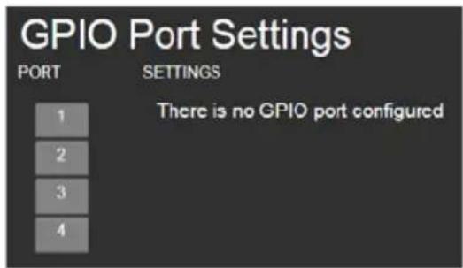
Figure 19: GPIO Port Settings Page – No GPIO Ports Configured
7.6.1 Setting Digital In Trigger Parameters
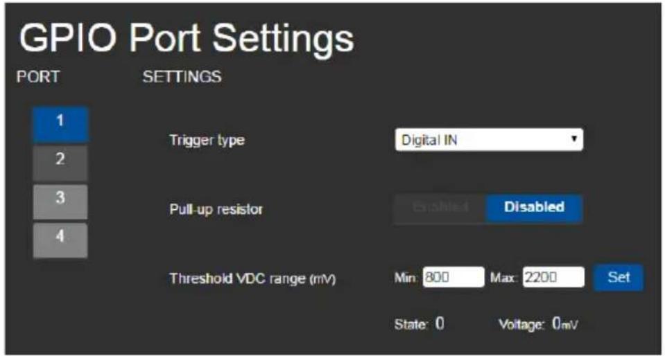
Figure 20: GPIO Port Settings Page Digital IN
Set the trigger type to Digital In (default). With this selection, the digital input trigger mode reads the digital input of an external sensor device that is connected to the GPIO port. It detects high (upon passing Max. threshold from Low state, default 2.2V) or low (upon passing Min threshold from High state, default 0.8V) port states according to the user defined voltage threshold levels:
• Pull-up resistor enabled (default)
Detects an open circuit as High, or a short to ground as Low. This is suitable for example, for a pushbutton switch (connecting one terminal of the switch to ground, and the other to the input) or for an alarm closing a circuit that activates a series of actions.
When the pull-up is enabled, the port state is high and to be triggered it must be pulled low by the externally connected sensor.
• Pull-up resistor disabled
Suitable, for example, for a high-temperature alarm that exceeds the maximum voltage threshold.
When disabled, the port state is low and to be triggered it must be pulled high by the externally connected sensor.
7.6.2 Setting Digital Out Trigger Parameters
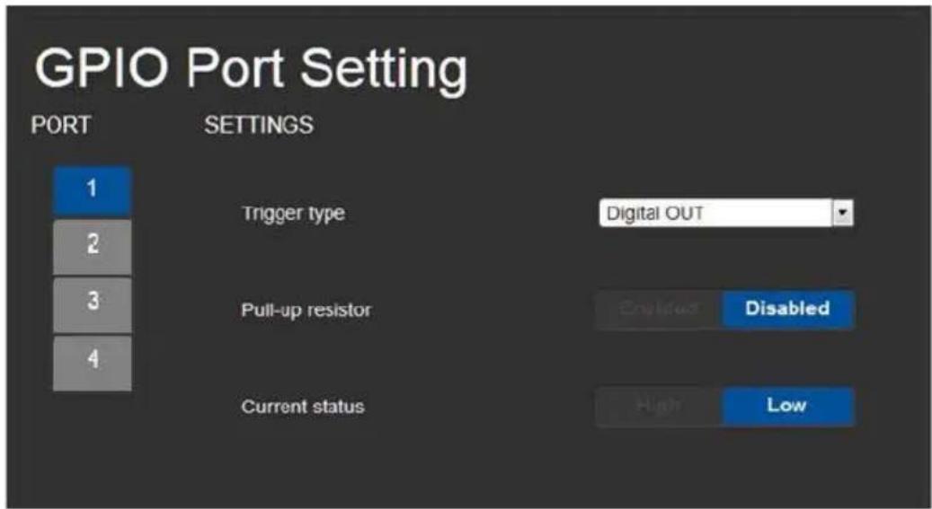
Figure 21: GPIO Port Settings Page Digital OUT
Set the trigger type to Digital Out. With this selection, the external device, (for example, an electric blind) is controlled by the FC-54P.
When selecting the Digital Out trigger type, the warning popup shown in Figure 22 is displayed.

Figure 22: Digital Out Selection Warning Popup
The digital output mode function is defined by the pull-up resistor setup:
- Pullup resistor enabled:
The port is used for controlling external devices such as room or light switches. The external source device determines the voltage output; the maximum voltage is 30V DC and the maximum current is 100mA.
Note: take care that the current in this configuration does not exceed 100mA!
When enabled, the port state is high by default. For the state to be low, you must click Low from the Current Status.
• Pullup resistor disabled (default):
The port can be used for controlling devices that accept a TTL signal such as for powering LEDs. The voltage output is TTL positive logic: open: \~ 3.5V; closed: \~ 0.3V.
When disabled, the port state is low by default and to set it high, you must click High from the Current Status.
7.6.3 Setting Analog In Trigger Parameters
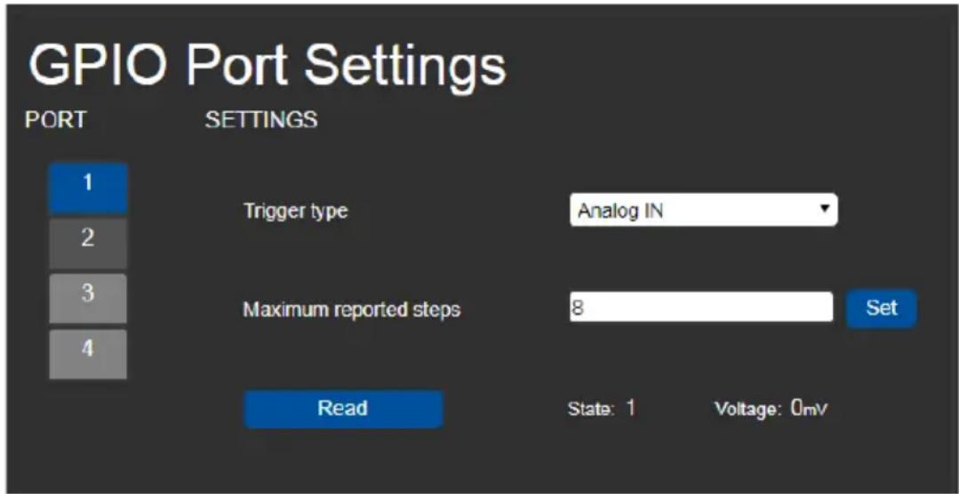
Figure 23: GPIO Port Settings Page Analog IN
Set the trigger type to Analog In. With this selection, the port is triggered by an analog external device, such as, a volume control device. The trigger is activated once when the detected voltage is within 0 to 30V DC voltage range.
You can select the number of steps the analog input signal will be divided into, starting with step 1 and with a maximum of 100 (default 8). The voltage of each step is dependent on the number of steps selected:
Individual step voltage = 30V / number of steps
When selecting the Analog In trigger type, the Pullup resistor and Threshold settings are disabled.
7.7 Setting Relay Port Status
The Relay Port Settings page allows you to turn the relays on and off to control relay-driven devices such as shades, projection screens and lighting systems.
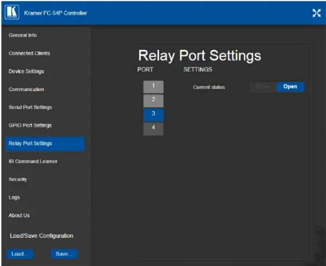
Figure 24: Relay Port Settings Page
The relay ports have the following characteristics:
• Rated at 30V DC and 1A
- Default state of normally open
- A non-latching relay function, that is, the contact is left open when unpowered or on power up state. This means that if a relay is closed and power is lost, the relay returns to its default state. To return it to its pre-power loss state, the setting must be changed using either the Web UI or a Protocol 3000 command
To close a relay, (for example, relay 2):
- On the Relay Setting page, click Port button 2 to select the second relay. The current relay status is shown to the right of the button.
- Click Close.
The relay closes, the button changes color, and the Relay 2 LED on the front panel lights green.

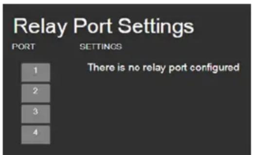
Note: When DIP-switches 1 and 2 are set up to GPIO, Relay ports 1 through 4 are grayed out and the following Relay port settings screen appears:
7.8 Configuring IR Command Learning
The IR Command Learner page allows you to teach the FC-54P IR commands. These can be saved for later use.
Note: While learning is in progress, the four IR Out LEDS light and the FC-54P is not available for normal operation.
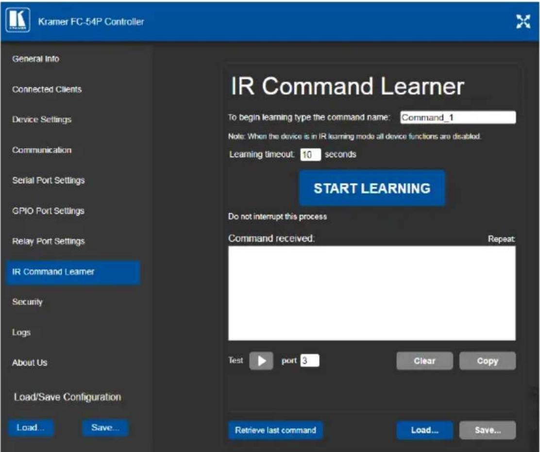
Figure 25: IR Command Learner Page
| Feature | Function |
| Command Name Field | Enter the required name for the command |
| Learning Timeout Set the time to | elapse before the learning mode is exited if no command is received |
| Start Learning Button | Press to start the learning process.Note: While learning is in progress, the four IR Out LEDS light and the FC-54P is not available for normal operation. |
| Command Received Window | Displays the command string received during the process. This command can be copied/pasted to another application |
| Test Button and Port Selection Spinner | Select the port on which to test the learned command and press the Test button to start the test |
| Retrieve Last Command Button | Press to retrieve that last command learned |
| Clear/Copy Buttons | Press to clear or copy the command received |
| Load/Save Buttons | Press Load to retrieve a previously saved command. Press Save to save the current command |
7.9 Activating Security
The Security page allows you to turn logon authentication on or off.
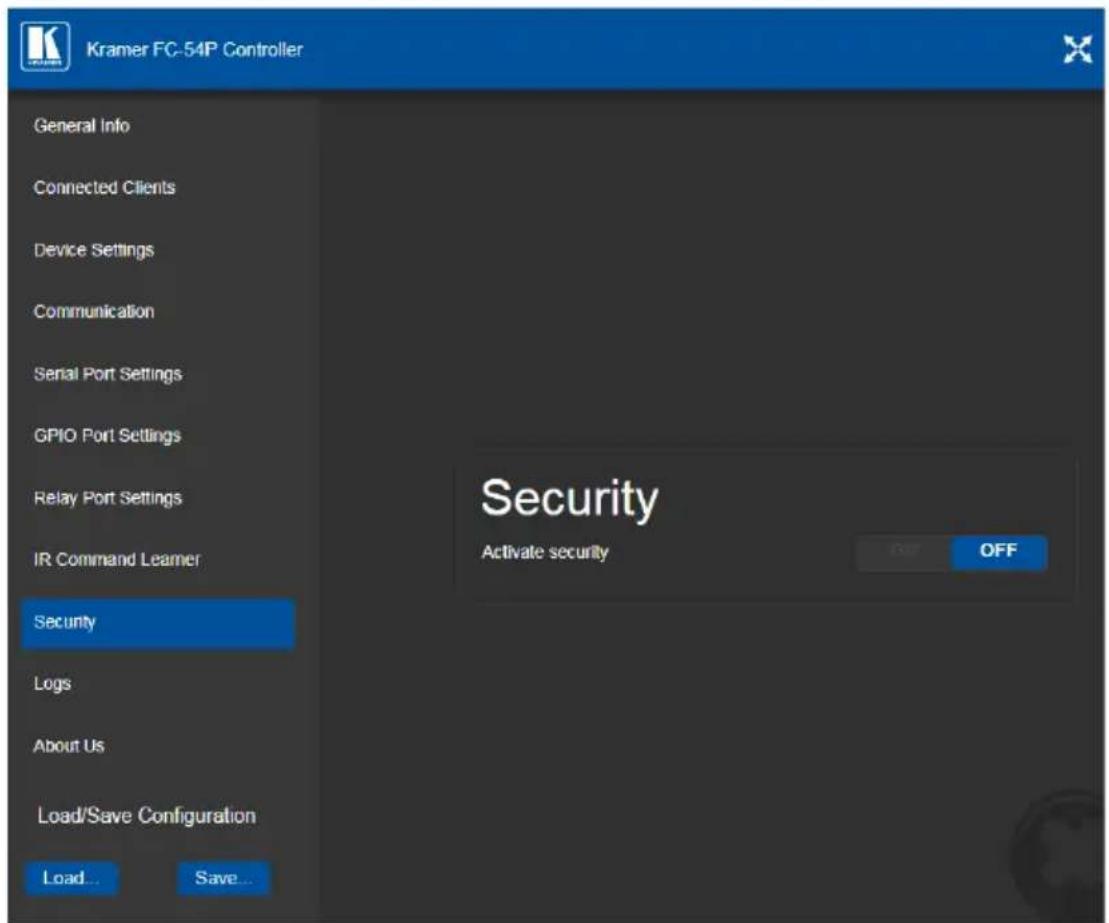
Figure 26: Security Page
When security is on, access to the Web UI is granted only on submission of a valid user and password. The default user ID is Admin and the password is Admin.
To activate Web UI security:
- On the Security page, click ON.
The confirmation popup is displayed as shown in Figure 27.
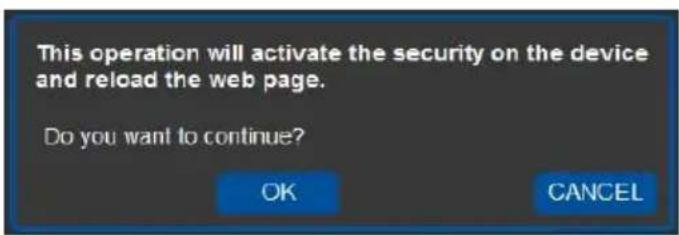
Figure 27: Security Confirmation Popup
2. Click OK.
The Authentication Required popup is displayed as shown in Figure 28.
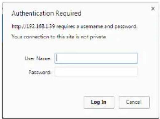
Figure 28: Authentication Required Popup
- Enter the default username and password.
- Click OK.
- Wait until the Web UI has reloaded. Click the Security page button.
The page show in Figure 29 is displayed.
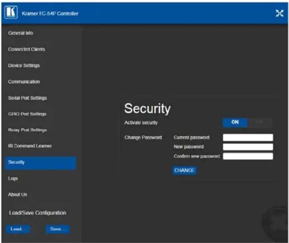
Figure 29: Security Activated Page
- If required, click OFF to turn security off, or change the password and click Change.
7.10 Using the Logs Page
The Logs page allows you to:
• View current logs
- Configure the logs
- Filter the logs
![Kramer FC-54P Controller General Info Connected Clients Device Settings Communication Serial Port Settings GPIO Port Settings Relay Port Settings IR Command Learner Security Logs About Us Load/Save Configuration Load Save Logs Date Time Type Client Event 493-05-00 00:00:52 INFO [Relay] RELAY : write command done for relay 2 493-05-00 00:00:52 INFO [Relay] RELAY : write command done for relay 1 493-05-00 00:00:52 INFO [Relay] RELAY : write command done for relay 4 493-05-00 00:00:52 INFO [Relay] RELAY : write command done for relay 3 493-05-00 00:00:52 INFO [Relay] RELAY : write command done for relay 2 493-05-00 00:00:52 INFO [Relay] RELAY : write command done for relay 1 LOG FILTER LOG CONFIG ✓ Device Control Device Control ✓ Tx Data Tr Data ✓ Rx Data Rx Data ✓ Relay Data ✓ Relay Data ✓ GPIO Data ✓ GPIO Data ✓ IR Data ✓ IR Data ✓ Errors Refresh](/content/2026/06/1199529/images/86de81359825a89f405dffab7b95cf847d418a9f1d63da516e4e8e9f98a04dce.jpg)
Figure 30: Logs Page
The display may not update automatically. Click Refresh to update the display.
Use the Log Filter check-boxes to select which events to display from the log. Use the Log Config check-boxes to select which events are recorded.
7.11 Kramer Information
The About Us page displays the Web UI version and the Kramer company details.
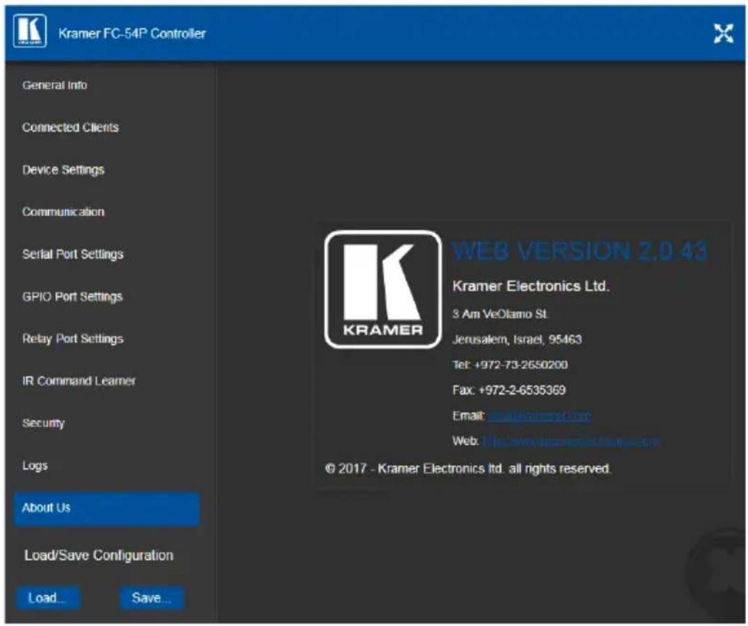
Figure 31: About Us Page
8 Using FC-54P Operations
This section explains how to use IR learning, reset the device and upgrade device firmware.
8.1 Using IR Learning
At the start and end of learning a message is sent to all attached clients.
To perform IR learning, the IR remote control must be approximately five to seven centimeters (2" and 2.7") from the FC-54P front panel.
Note: While learning is in progress, the FC-54P is not available for normal operation.
To teach the FC-54P an IR command:
- Put the FC-54P in IR Learning mode either by sending the Protocol 3000 command, (see Section 11.2) or by using the Web pages, (see Section 7.8). The device is no longer in normal operation, and the FC-54P sends an IR Learning start message to all connected clients.
- Using the IR remote control, send the required command to the FC-54P. The FC-54P processes the IR detected signal and generates the signal-associated pronto code to be used by the driver. When using the Web page for IR learning, the FC-54P also displays the learned command code on screen. (This command can be copied/pasted to other applications, for example, control software when creating a driver.) The FC-54P then sends the IR Learning stop message to all connected clients to indicate return to normal operation.
- Optional—Test the command if using the IR Learning Web page. Test results are displayed on screen.
- Save the learned command.
8.2 Resetting to the Factory Default Settings
To reset the device to its factory default settings:
- Turn off the power to the device.
- Press and hold the Reset button on the front panel.
- Turn on the power to the device while holding down the Reset button for a few seconds.
- Release the button.
The device is reset to the factory default settings.
8.3 Upgrading the Firmware
For instructions on upgrading the firmware see the "Kramer K-Upload User Manual".
9 Technical Specifications
| Ports | 4 GPIO | On 2-pin terminal blocks |
| 2 relays | On 3-pin terminal blocks | |
| 2 RS-232 bidirectional serial or 4 IR (selectable) | On 3-pin terminal blocks | |
| 1 LAN | On an RJ-45 connector | |
| 1 IR sensor | For IR learning | |
| 1 mini USB connector | For programming | |
| Serial | Serial port baud rates | 1200, 2400, 4800, 9600, 19200, 38400, 57600, 15200bps |
| RS-232 communication | Transparent up to 115200bps | |
| IR | IR emitter cable range | 80m (260ft) |
| IR output frequencies 20kHz to 1.2MHz | ||
| IR input frequencies | 20kHz to 60kHz | |
| Data and Connections | Maximum data handling of device | Up to 150kbps (summed on all ports, see Section 9.1) |
| Maximum simultaneous IP-client connections | 40 | |
| Power | Power consumption | 5V DC, 400mA |
| Power source | PoE or a USB power source (for extra power resiliency, connect to the 5V DC power supply) | |
| Cooling | Convection ventilation | |
| Environmental Conditions | Operating temperature | 0° to +40°C (32° to 104°F) |
| Storage temperature | -40° to +70°C (-40° to 158°F) | |
| Humidity | 10% to 90%, RHL non-condensing | |
| Regulatory Compliance | Vibration | ISTA 1A in carton (International Safe Transit Association) |
| Safety CE | ||
| Environmental | RoHs, WEEE | |
| General | Enclosure type | Aluminum |
| Net dimensions | 18.75cm x 11.5cm x 2.54cm (2.45" x 2.0" x 1.0") W, D, H. | |
| Net weight | 0.4kg (094lbs) approx. | |
| Shipping dimensions | 34.5cm x 16.5cm x 5.2cm (6.2" x 4.7" x 3.4") W, D, H. | |
| Shipping weight | 0.94kg (2.1lbs) approx. | |
| Accessories | Included | Bracket set, power supply |
| Optional | RK-T2B 19" rack adapter, IR and serial cables - see www.kramerav.com/product/FC-54P | |
| Specifications are subject to change without notice at www.kramerav.com | ||
9.1 Data Handling Performance
The FC-54P is designed to support mainly AV-relevant RS-232 communication.
These devices must have overall data bandwidth limits high enough in most AV installations to support the required communication bandwidth.
In extremely demanding cases, we recommend that you take into account the bandwidth limitations.
The total sustained data bandwidth that each device can handle for all ports simultaneously is 150kbps.
9.2 Example Bandwidth Calculation
The FC-54P has two serial ports. Each serial port can support up to:
- 150kbps / 2 = 75kbps
If each protocol command is 100 bytes, (that is, 800 bits), you can safely send and receive a minimum of 96 commands per second on each serial port. This is shown using the following calculation:
(150kbps * 1024) / 800 bits / 2 = 96
The same calculation applies to all devices. A similar calculation applies when fewer ports are used at the same time where a higher bandwidth per port can be achieved.
In critical applications requiring a lossless data transfer, we recommend that communication on all the other ports is stopped when making a long file transfer (for example, when performing a firmware upgrade via one of the serial ports).
10 Default Parameters
| RS-232 | |
| Protocol 3000 | |
| Baud Rate: | 115200 |
| Data Bits: | 8 |
| Stop Bits: | 1 |
| Parity: | None |
Note: The FC-54P is dispatched from the factory with DHCP enabled and a random IP address. After performing a factory reset, the DHCP and the IP address are set to the values shown below.
| Ethernet | |
| DHCP: | Off |
| IP Address: | 192.168.1.39 |
| Host Name: | FC-54P-xxxxwhere xxxx are the last four digits of the serial number of the device |
| Subnet Mask: | 255.255.0.0 |
| Gateway: | 192.168.0.1 |
| Maximum Simultaneous Connections: | 40 |
| TCP Port 1: | 5001 |
| TCP Port 2: | 5002 |
| UDP Port: | 50000 |
Default Logon Authentication
| Web UI Access | |
| User name: | Admin |
| Password: | Admin |
11 Kramer Protocol 3000
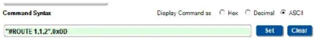
The FC-54P can be operated using the Kramer Protocol 3000 serial commands. The command framing varies according to how you interface with the FC-54P. For example, a basic video input switching command that routes a layer 1 video signal to HDMI out 1 from HDMI input 2 (ROUTE 1, 1, 2), is entered as follows:
• Terminal communication software, such as Hercules:
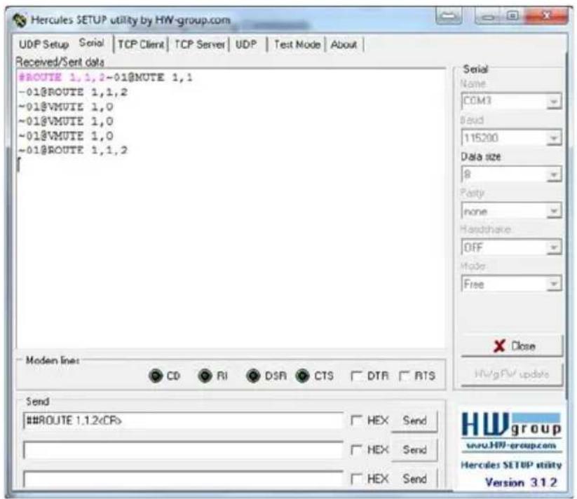

The framing of the command varies according to the terminal communication software.
• K-Touch Builder (Kramer software):
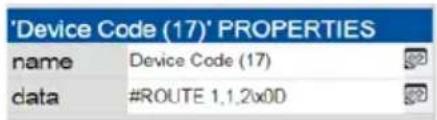
• K-Config (Kramer configuration software):

All the examples provided in this section are based on using the K-Config software.
You can enter commands directly using terminal communication software (e.g., Hercules) by connecting a PC to the serial or Ethernet port on the FC-54P. To enter CR press the Enter key (LF is also sent but is ignored by the command parser).
Commands sent from various non-Kramer controllers (e.g., Crestron) may require special coding for some characters (such as, /x##). For more information, refer to your controller's documentation.
11.1 Kramer Protocol 3000 – Syntax
11.1.1 Host Message Format
| Start | Address (optional) | Body | Delimiter |
| # | Destination_id@ | Message | CR |
11.1.1.1 Simple Command
Command string with only one command without addressing:
| Start | Body | Delimiter |
| # | Command SP Parameter_1,Parameter_2,... | CR |
11.1.1.2 Command String
Formal syntax with commands concatenation and addressing:
| Start | Address | Body | Delimiter |
| # | Destination_id@ | Command_1 Parameter1_1,Parameter1_2,.../Command_2 Parameter2_1,Parameter2_2,.../Command_3 Parameter3_1,Parameter3_2,...|... | CR |
11.1.2 Device Message Format
| Start | Address (optional) | Body | Delimiter |
| ~ | Sender_id@ | Message | CR LF |
11.1.2.1 Device Long Response
Echoing command:
| Start | Address (optional) | Body | Delimiter |
| ~ | Sender_id@ | Command SP [Param1,Param2 ...] result | CR LF |
CR = Carriage return (ASCII 13 = 0x0D)
= Line feed (ASCII 10 = 0 × 0 ~A)
SP = Space (ASCII 32 = 0x20)
11.1.3 Command Terms
Command
A sequence of ASCII letters ('A'-'Z', 'a'-'z' and '-'').
Command and parameters must be separated by at least one space.
Parameters
A sequence of alphanumeric ASCII characters ('0'-9', 'A'-Z', 'a'-z' and some special characters for specific commands). Parameters are separated by commas.
Message string
Every command entered as part of a message string begins with a message starting character and ends with a message closing character.
Note: A string can contain more than one command. Commands are separated by a pipe ( ' |' ) character.
Message starting character
'#' – For host command/query
'\~' – For device response
Device address (Optional, for K-NET)
K-NET Device ID followed by '@'
Query sign
'?' follows some commands to define a query request.
Message closing character
CR- For host messages; carriage return (ASCII 13)
CRLF – For device messages; carriage return (ASCII 13) + line-feed (ASCII 10)
Command chain separator character
When a message string contains more than one command, a pipe ( ' |' ) character separates each command.
Spaces between parameters or command terms are ignored.
11.1.4 Entering Commands
You can directly enter all commands using a terminal with ASCII communications software, such as HyperTerminal, Hercules, etc. Connect the terminal to the serial or Ethernet port on the Kramer device. To enter CR press the Enter key.
( LF is also sent but is ignored by command parser).
For commands sent from some non-Kramer controllers like Crestron, some characters require special coding (such as, /X##). Refer to the controller manual.
11.1.5 Command Forms
Some commands have short name syntax in addition to long name syntax to allow faster typing. The response is always in long syntax.
11.1.6 Chaining Commands
Multiple commands can be chained in the same string. Each command is delimited by a pipe character ("|"). When chaining commands, enter the message starting character and the message closing character only once, at the beginning of the string and at the end.
Commands in the string do not execute until the closing character is entered.
A separate response is sent for every command in the chain.
11.1.7 Maximum String Length
64 characters
11.2 Kramer Protocol 3000 – Command List
| Command | Description |
| # | Protocol handshaking |
| BUILD-DATE | Read device build date |
| COM-ROUTE | Set/get tunneling port routing |
| COM-ROUTE-ADD | Add communication route tunnel connection |
| COM-ROUTE-REMOVE | Remove communication route tunnel connection |
| DEL | Deletes a file |
| DIR | List files |
| ETH-PORT | Sets protocol port |
| ETH-TUNNEL | Get parameters for open tunnels |
| FACTORY | Restart the machine with the default |
| FORMAT | Format the file system |
| FS-FREE | Print free file space |
| GET | Get file content |
| GPIO-CFG | Set/get HW GPIO configuration |
| GPIO-STATE | Set/get HW GPIO state |
| GPIO-STEP | Set/get HW GPIO step |
| GPIO-THR | Set/get HW GPIO threshold voltage |
| GPIO-VOLT | Get HW GPIO voltage level |
| HELP | List of commands |
| IR-LEARN | Send IR learning command |
| IR-SND | Send IR command to port |
| IR-STOP | Stop IR command to port |
| LOGIN | Set/get protocol permission |
| LOGOUT | Demotes the terminal security level to minimum |
| MACH-NUM | Set device ID |
| MODEL | Read device model |
| NAME | Set/get device (DNS) name |
| NAME-RST | Reset device name to default |
| NET-DHCP | Set/get DHCP mode |
| NET-GATE | Set/get gateway IP |
| NET-IP | Set/get device IP address |
| NET-MAC | Get the MAC address |
| NET-MASK | Set/get the device subnet mask |
| PASS | Set/get the password for login level |
| PORT-LOCK | Set/get the port lock state |
| PORT-TYPE | Set/get the port type |
| PROT-VER | Get protocol version |
| RELAY-STATE | Set/get relay state |
| RESET | Reset device |
| SECUR | Set/get current security state |
| SN | Get device serial number |
| TIME | Set/get the time |
| TIME-LOC | Set/get local time offset from UTC/GMT |
| TIME-SRV | Set/get time synchronization from server |
| UART | Set/get a port serial parameters |
| VERSION | Get firmware version number |
11.3 Kramer Protocol 3000 – Detailed Commands
This section lists the detailed commands applicable to the FC-54P.
11.3.1 #
| Functions | Permission | Transparency | |
| Set: | # | End User Public | |
| Get: | - | -- | |
| Description Syntax | |||
| Set: Protocol handshaking | #CR | ||
| Get: -- | |||
| Response | |||
| ~nn@SPOKCR LF | |||
| Parameters | |||
| Response Triggers | |||
| Notes | |||
| Validates the Protocol 3000 connection and gets the machine numberStep-in master products use this command to identify the availability of a device | |||
| K-Config Example | |||
| “#”, 0x0D | |||
11.3.2 BUILD-DATE
| Functions | Permission | Transparency | |
| Set: | - | - - | |
| Get: | BUILD-DATE? | End User Public | |
| Description Syntax | |||
| Set: | - - | ||
| Get: | get device build date | #BUILD-DATE?CR | |
| Response | |||
| ~nn@BUILD-DATESPdateSPtimeCR LF | |||
| Parameters | |||
| date-Format: YYYY/MM/DD where YYYY = Year, MM = Month, DD = Day time-Format: hh:mm:ss where hh = hours, mm = minutes, ss = seconds | |||
| Response Triggers | |||
| Notes | |||
| K-Config Example | |||
| "#BUILD-DATE?", 0x0D | |||
11.3.3 COM-ROUTE
| Functions | Permission | Transparency | |
| Set: | COM-ROUTE | Administrator Internal | |
| Get: | COM-ROUTE? | End User Internal | |
| Description Syntax | |||
| Set: | Set tunneling port routing | #COM-ROUTE _SP COM_Num, portType, ETHPort, ETH_rep_en, TCP_keep_alive_timing _CR | |
| Get: | Get tunneling port routing | #COM-ROUTE? _SP COM_Num _CR | |
| Response | |||
| ~nn@COM-ROUTE _SP COM_Num, portType, ETHPort, ETH_rep_en, TCP_keep_alive_timing _CR LF | |||
| Parameters | |||
| COM_Num - machine dependent portType - 1 (UDP), 2 (TCP) ETHPort - TCP/UDP port number ETH_rep_en - 1 (COM port sends replies to new clients), 0 (COM port does not send replies to new clients) TCP_keep_alive_timing - 0-3600 seconds - every x seconds the device sends an empty string to TCP client ("/0") | |||
| Response Triggers | |||
| Notes | |||
| This command sets tunneling port routing. Every com port can send or receive data from the ETH port. All com ports can be configured to the same ETH port. | |||
| K-Config Example | |||
| Set COM1 as RS-232, port 1, Eth port 1, send replies, keep alive 30 seconds: "#COM-ROUTE 1,1,1,1,30", 0x0D | |||
11.3.4 COM-ROUTE-ADD
| Functions | Permission | Transparency | |
| Set: | COM-ROUTE-ADD | Administrator Internal | |
| Get: - - | - | ||
| Description Syntax | |||
| Set: | Add a communication route tunnel connection | #COM-ROUTE-ADDSPComNum, PortType, EthPort, EthRepEn, TimeoutCR | |
| Get: - - | |||
| Response | |||
| ~nn@COM-ROUTE-ADDSP ComNum, PortType, EthPort, EthRepEn, TimeoutCR LF | |||
| Parameters | |||
| COMNum - machine dependent portType - 1 (UDP), 2 (TCP) ETHPort - TCP/UDP port number ETHRepEn - 1 (COM port sends replies to new clients), 0 (COM port does not send replies to new clients) Timeout - Keep alive timeout in seconds (1 to 3600) | |||
| Response Triggers | |||
| Notes | |||
| K-Config Example | |||
| Add COM1 port as TCP, port 1, Eth port 1, send replies, keep alive 30 seconds: "#COM-ROUTE-ADD 1,1,1,1,30", 0x0D | |||
11.3.5 COM-ROUTE-REMOVE
| Functions | Permission | Transparency | |
| Set: | COM-ROUTE-REMOVE | Administrator Internal | |
| Get: | - | - | - |
| Description | Syntax | ||
| Set: | Remove a communication route tunnel connection | #COM-ROUTE-REMOVESP ComNumCR | |
| Get: | - | - | |
| Response | |||
| ~nn@COM-ROUTE-REMOVESP ComNumCR LF | |||
| Parameters | |||
| ComNum - machine dependent | |||
| Response Triggers | |||
| Notes | |||
| K-Config Example | |||
| Remove comm port 1:"#COM-ROUTE-REMOVE 1", 0x0D | |||
11.3.6 DEL
| Functions | Permission | Transparency | |
| Set: | DEL | Administrator Public | |
| Get: | - | -- | |
| Description Syntax | |||
| Set: Delete file | #DELSPfile_nameCR | ||
| Get: | |||
| Response | |||
| ~nn@DELSPfile_nameCR | |||
| Parameters | |||
| file_name - name of file to delete (file names are case-sensitive) | |||
| Response Triggers | |||
| K-Config Example | |||
| Delete a file named “test”:“DEL test”, 0x0D | |||
11.3.7 DIR
| Functions | Permission | Transparency | |
| Set: | DIR | Administrator | Public |
| Get: | - | -- | |
| Description Syntax | |||
| Set: | List files in device | #DIRCR | |
| Get: -- | |||
| Response | |||
| Multi-line:~nn@DIRCR LFfile_nameTAB file_size SP bytes, SP ID: SP file_id CR LFTAB free_size SP bytes. CR LF | |||
| Parameters | |||
| file_name - name of filefile_size - file size in bytes. A file can take more space on device memoryfile_id - internal ID for file in file systemfree_size - free space in bytes in device file system | |||
| Response Triggers | |||
| K-Config Example | |||
| "DIR", 0x0D | |||
11.3.8 ETH-PORT
| Functions | Permission | Transparency | |
| Set: | ETH-PORT | Administrator Public | |
| Get: | ETH-PORT? | End User Public | |
| Description Syntax | |||
| Set: Set Ethernet port protocol | #ETH-PORTSPportType,ETHPortCR | ||
| Get: Get Ethernet port protocol | #ETH-PORT?SPportTypeCR | ||
| Response | |||
| ~nn@ETH-PORTSPportType,ETHPortCR LF | |||
| Parameters | |||
| portType - 1 (UDP), 2 (TCP)ETHPort - TCP/UDP port number | |||
| Response Triggers | |||
| K-Config Example | |||
| Set ETH port 1 to UDP:"ETH-PORT 2,1",0x0D | |||
11.3.9 ETH-TUNNEL
| Functions | Permission | Transparency | |
| Set: | - | - | - |
| Get: | ETH-TUNNEL? | Administrator | Internal |
| Description Syntax | |||
| Set: | |||
| Get: | Get parameters for open tunnels | #ETH-TUNNEL? SP TunnelId CR | |
| Response | |||
| ~nn@ETH-TUNNEL SP TunnelId, ComNum, PortType, EthPort, EthIp, RemotPort, EthRepEn, Wired CR LF | |||
| Parameters | |||
| TunnelId - tunnel ID number: 1-64 (depends on number of tunnel connections), * (all tunnel connections)ComNum - UART number portType - 1 (UDP), 2 (TCP)ETHPort - TCP/UDP port numberEthIp - client IP addressRemotPort - remote port numberEthRepEn - 1 (COM port sends replies to new clients), 0 (COM port does not send replies to new clients)Wired - 1 (wired connection), 0 (not wired connection) | |||
| Response Triggers | |||
| Notes | |||
| The response displays each tunnel in a separate line. | |||
| K-Config Example | |||
| "ETH-TUNNEL? 1", 0x0D | |||
11.3.10 FACTORY
| Functions | Permission | Transparency | |
| Set: | FACTORY | End User Public | |
| Get: - | - - | ||
| Description Syntax | |||
| Set: | Reset device to factory default configuration | #FACTORYCR | |
| Get: - - | |||
| Response | |||
| ~nn@FACTORYSPOKCR LF | |||
| Parameters | |||
| Response Triggers | |||
| Notes | |||
| This command deletes all user data from the device. The deletion can take some time.Your device may require powering off and powering on for the changes to take effect. | |||
| K-Config Example | |||
| "#FACTORY", 0x0D | |||
11.3.11 FORMAT
| Functions | Permission | Transparency | |
| Set: | FORMAT | Administrator Public | |
| Get: | - | -- | |
| Description Syntax | |||
| Set: Format file system | #FORMATCR | ||
| Get: | - | - | |
| Response | |||
| ~nn@FORMATSPOKCR LF | |||
| Parameters | |||
| Response Triggers | |||
| Notes | |||
| Response could take several seconds until formatting completes | |||
| K-Config Example | |||
| "#FORMAT", 0x0D | |||
11.3.12 FS-FREE
| Functions | Permission | Transparency | |
| Set: | - | -- | |
| Get: | FS-FREE? | Administrator Public | |
| Description Syntax | |||
| Set: - - | |||
| Get: Get file system free space | #FS-FREE?CR | ||
| Response | |||
| ~nn@FS_FREESP free_size CR LF | |||
| Parameters | |||
| free_size - free size in device file system in bytes | |||
| Response Triggers | |||
| K-Config Example | |||
| "#FS-FREE?", 0x0D | |||
11.3.13 GET
| Functions | Permission | Transparency | |
| Set: | - | - | - |
| Get: | GET | Administrator Public | |
| Description Syntax | |||
| Set: - - | |||
| Get: Get file | #GETSPfile_nameCR | ||
| Response | |||
| Multi-line:~nn@GETSPfile_name, file_sizeSPREADYCR LFcontents~nn@GETSPfile_nameSPOKCR LF | |||
| Parameters | |||
| file_name - name of file to get contentscontents - byte stream of file contentsfile_size - size of file (device sends it in response to give user a chance to get ready) | |||
| Response Triggers | |||
| K-Config Example | |||
| Get a file named "test":"#GET test", 0x0D | |||
11.3.14 GPIO-CFG
| Functions | Permission | Transparency | |
| Set: | GPIO-CFG | End User | Public |
| Get: | GPIO-CFG? | End User | Public |
| Description Syntax | |||
| Set: Set HW GPIO configuration | #GPIO-CFGSPHwGpioNumber, HwGpioType, HwGpioDir, PullupCR | ||
| Get: Get HW GPIO configuration | #GPIO-CFGSPHw GpioNumberCR | ||
| Response | |||
| ~nn@GPIO-CFGSPHwGpioNum, HwGpioType, HwGpioDirCR LF | |||
| Parameters | |||
| HwGpioNumber - hardware GPIO number: 1-nHwGpioType - hardware GPIO type: 0 (analog), 1 (digital)HwGpioDir - hardware GPIO direction: 0 (input), 1 (output)Pullup - enable/disable pull-up: 0 (disable), 1 (enable) | |||
| Response Triggers | |||
| Notes | |||
| K-Config Example | |||
| Configure GPIO 2 to analog input with pullup disabled):“#GPIO-CFG 2, 0, 0, 0”, 0x0D | |||
11.3.15 GPIO-STATE
| Functions | Permission | Transparency | |
| Set: | GPIO-STATE | End User | Public |
| Get: | GPIO-STATE? | End User | Public |
| Description Syntax | |||
| Set: Set HW GPIO state | #GPIO-STATE SP HwGpioNumber, HwGpioState CR | ||
| Get: Get HW GPIO state | #GPIO-STATE SP HwGpioNumber CR | ||
| Response | |||
| ~nn@GPIO-STATE SP HwGpioNumber, HwGpioState CR LF | |||
| Parameters | |||
| HwGpioNumber - hardware GPIO number: 1-nHwGpioState - hardware GPIO state - see note below | |||
| Response Triggers | |||
| Notes | |||
| GPIO-STATE? can only be sent in digital out mode and the answer is 0 (low), 1 (high). In all other modes an error message is sent.The device uses this command to notify the user of any change regarding the step and voltage in:In digital mode the answer is 0 (low), 1 (high)In analog mode the answer is 0 to 100 | |||
| K-Config Example | |||
| Configure GPIO 2 to low state:"#GPIO-STATE 2,0",0x0D | |||
11.3.16 GPIO-STEP
| Functions | Permission | Transparency | |
| Set: | GPIO-STEP | End User | Public |
| Get: | GPIO-STEP? | End User | Public |
| Description Syntax | |||
| Set: Set HW GPIO step | #GPIO-STEP SP HwGpioNumber, Step CR | ||
| Get: Get HW GPIO step | #GPIO-STEP SP HwGpioNumber CR | ||
| Response | |||
| ~nn@GPIO-STEP SP HwGpioNumber, NumOfStep, CurrentStep CR LF | |||
| Parameters | |||
| HwGpioNumber - HW GPIO number: 1-nNumOfStep - the configuration step - see note belowCurrentStep - the actual step depending on the measured voltage | |||
| Response Triggers | |||
| Notes | |||
| In digital mode the response is 2In analog mode the response is 1 to 100In other modes an error is returned | |||
| K-Config Example | |||
| Set GPIO 2 step 1 to 50:"#GPIO-STEP 2,1,50",0x0D | |||
11.3.17 GPIO-THR
| Functions | Permission | Transparency | |
| Set: | GPIO-THR | End User | Public |
| Get: | GPIO-THR? | End User | Public |
| Description Syntax | |||
| Set: Set HW GPIO voltage levels | #GPIO-THRspHwGpioNumber,LowLevel,HighLevelCR | ||
| Get: Get HW GPIO voltage levels | #GPIO-THR?spHwGpioNumberCR | ||
| Response | |||
| ~nn@GPIO-THRspHwGpioNumber,LowLevel,HighLevelCR LF | |||
| Parameters | |||
| HwGpioNumber - hardware GPIO number: 1-nLowLevel - voltage 500 to 28000 millivoltsHighLevel - voltage 2000 to 30000 millivolts | |||
| Response Triggers | |||
| Notes | |||
| K-Config Example | |||
| Set GPIO 1 voltage levels between 600mV to 15000mV:"#GPIO-THR 1,600,15000",0x0D | |||
11.3.18 GPIO-VOLT
| Functions | Permission | Transparency | |
| Set: | - | - | - |
| Get: | GPIO-VOLT? | End User | Public |
| Description Syntax | |||
| Set: | |||
| Get: Get voltage levels of HW GPIO | #GPIO-VOLT? SP HwGpioNumber CR | ||
| Response | |||
| ~nn@GPIO-VOLT SP HwGpioNumber, Voltage CR LF | |||
| Parameters | |||
| HwGpioNumber - hardware GPIO number: 1-nVoltage - voltage 0 to 30000 millivolts | |||
| Response Triggers | |||
| Notes | |||
| This command is not available in digital out mode | |||
| K-Config Example | |||
| "#GPIO-VOLT? 1", 0x0D | |||
11.3.19 HELP
| Functions | Permission | Transparency | |
| Set: | - | - - | |
| Get: | HELP | End User Public | |
| Description Syntax | |||
| Set: - - | |||
| Get: | Get command list or help for specific command | 1. #HELPCR2. #HELPSPCOMMAND_NAMECR | |
| Response | |||
| 1. Multi-line: ~nn@Device available protocol 3000 commands: CR LFcommand, SP command...CR LF2. Multi-line: ~nn@HELPSPcommand: CR LFdescriptionCR LFUSAGE: usageCR LF | |||
| Parameters | |||
| COMMAND_NAME – name of a specific command | |||
| Response Triggers | |||
| Notes | |||
| To get help for a specific command use: HELPSPCOMMAND_NAMECR LF | |||
| K-Config Example | |||
| "#HELP", 0x0D | |||
11.3.20 IR-LEARN
| Functions | Permission | Transparency | |
| Set: | IR-LEARN | End User Public | |
| Get: | - | -- | |
| Description | Syntax | ||
| Set: | Send IR learning command | #IR-LEARNSPCommandName,TimeoutCR | |
| Get: | - | - | |
| Response | |||
| ~nn@IR-LEARNSPCommandName,IR_StatusCR LF | |||
| Parameters | |||
| CommandName – String: IR command name limited to 15 chars. Controlling device must send the correct name (whitespace or commas forbidden)Timeout - 1 to 60 (timeout in seconds)IR_Status - 0 (sent), 1 (stop), 2 (done), 3 (busy), 4 (wrong parameter), 5 (nothing to stop), 6 (start), 7 (timeout), 8 (error) | |||
| Response Triggers | |||
| K-Config Example | |||
| Send the IR learning command volume up with a 3 second timeout:"#IR-LEARN vol_up,3",0x0D | |||
11.3.21 IR-SND
| Functions | Permission | Transparency | |
| Set: | IR-SND | End User Public | |
| Get: | - | -- | |
| Description Syntax | |||
| Set: Send IR command to port | #IR-SNDSPPortNum, Cmdid, CmdName, Repeat, TotalPackages, PackageNum,CR | ||
| Get: -- | |||
| Response | |||
| ~nn@IR-SNDSPPortNum, Cmdid, CmdName, StatusCR LF | |||
| Parameters | |||
| PortNum - IR port (1 to 4) transmitting the command. '*' broadcasts to all portsCmdid - serial number of command for flow control and response commands from deviceCmdName - command name (length limit 15 chars)Repeat - number of times the IR command is transmitted (limited to 50; repeats >50 are truncated to 50), 1 (default)TotalPackages - number of messages the original command was divided into, 1 (default)PackageNum - chunk serial number (only valid when Chnk_Num >1)Pronto command - Pronto format command (in HEX format, without leading zeros or '0x' prefix)Status-0 (IR_SENT), 1 (IR_STOP), 2 (IR_BUSY), 3 (IR_WRONG_PARAM), 4 (IR-NOTHING_TO_STOP) | |||
| Response Triggers | |||
| K-Config Example | |||
| Send a volume up command to port 3 and repeat five times:"#IR-SND 3,04,vol_up,5,1,1,4E 23 C4...",0x0D | |||
11.3.22 IR-STOP
| Functions | Permission | Transparency | |
| Set: | IR-STOP | End User Public | |
| Get: | - | -- | |
| Description Syntax | |||
| Set: Send IR stop command to port | #IR-STOPSPPortNum, Cmdid, CmdNameCR | ||
| Get: -- | |||
| Response | |||
| ~nn@IR-STOPSPPortNum, Cmdid, CmdName, StatusCR LF | |||
| Parameters | |||
| PortNum - IR port (1 to 4) transmitting the command. '*' broadcasts to all portsCmdid - serial number of command for flow control and response commands from deviceCmdName - a string, the alias of the IR command. The controlling device is responsible for sending the correct nameStatus - 0 (IR_SENT), 1 (IR_STOP), 2 (IR_BUSY), 3 (IR_WRONG_PARAM),4 (IR-NOTHING_TO_STOP) | |||
| Response Triggers | |||
| K-Config Example | |||
| Send a power off command to IR port 2:"#IR-STOP 2,06,power_off",0x0D | |||
11.3.23 LOGIN
| Functions | Permission | Transparency | |
| Set: | LOGIN | Not Secure Public | |
| Get: | LOGIN? | Not Secure Public | |
| Description Syntax | |||
| Set: Set protocol permission | #LOGINSP login_level, passwordCR | ||
| Get: | Get current protocol permission level | #LOGIN?CR | |
| Response | |||
| Set: ~nn@LOGINSP login_level, passwordSPOKCR LFor~nn@LOGINSPERRSP004CR LF (if bad password entered)Get: ~nn@LOGINSP login_levelCR LF | |||
| Parameters | |||
| login_level-level of permissions required: User, Adminpassword-predefined password (by PASS command). Default password is an empty string | |||
| Response Triggers | |||
| Notes | |||
| When the permission system is enabled, LOGIN enables running commands with the User orAdministrator permission levelWhen set, login must be performed upon each connectionThe permission system works only if security is enabled with the SECUR command. It is not mandatory to enable the permission system in order to use the device | |||
| K-Config Example | |||
| Set the protocol permission level to Admin (when the password defined in the PASS command is 33333): "#LOGIN Admin, 33333", 0x0D | |||
11.3.24 LOGOUT
| Functions | Permission | Transparency | |
| Set: | LOGOUT | Not Secure | Public |
| Get: | - | - - | |
| Description Syntax | |||
| Set: | Cancel current permission level | #LOGOUTCR | |
| Get: - - | |||
| Response | |||
| ~nn@LOGOUTSPOKCR LF | |||
| Parameters | |||
| Response Triggers | |||
| Notes | |||
| Logs out from User or Administrator permission levels | |||
| K-Config Example | |||
| "#LOGOUT", 0x0D | |||
11.3.25 MACH-NUM
| Functions | Permission | Transparency | |
| Set: | MACH-NUM | End User Public | |
| Get: | -- | ||
| Description Syntax | |||
| Set: Set machine number (device ID) | #MACH-NUMSPmachine_numberCR | ||
| Get: -- | |||
| Response | |||
| ~nn@MACH-NUMSPmachine_numberCR LF | |||
| Parameters | |||
| machine_number - New machine number | |||
| Response Triggers | |||
| Notes | |||
| The new machine number is only set after restarting the device. | |||
| K-Config Example | |||
| "#MACH-NUM 4",0x0D | |||
11.3.26 MODEL
| Functions | Permission | Transparency | |
| Set: | - | - | - |
| Get: | MODEL? | End User Public | |
| Description Syntax | |||
| Set: | - | - | |
| Get: Get device model | #MODEL?CR | ||
| Response | |||
| ~nn@MODELSPmodel_nameCR LF | |||
| Parameters | |||
| model_name - String of up to 19 printable ASCII chars | |||
| Response Triggers | |||
| Notes | |||
| This command identifies equipment connected to Step-in master products and notifies of identity changes to the connected equipment. The Matrix saves this data in memory to answer REMOTE-INFO requests | |||
| K-Config Example | |||
| "#MODEL?", 0x0D | |||
11.3.27 NAME
| Functions | Permission | Transparency | |
| Set: | NAME | Administrator Public | |
| Get: | NAME? | End User Public | |
| Description Syntax | |||
| Set: Set machine (DNS) name | #NAME SP machine_name CR | ||
| Get: Get machine (DNS) name | #NAME ?CR | ||
| Response | |||
| Set: ~nn@NAME SP machine_name CR LF | |||
| Get: ~nn@NAME ?SP machine_name CR LF | |||
| Parameters | |||
| machine_name - string of up to 15 alpha-numeric chars (can include hyphen, not at the beginning or end) | |||
| Response Triggers | |||
| Notes | |||
| The machine name is not the same as the model name. The machine name is used to identify a specific machine or a network in use (with DNS feature on) | |||
| K-Config Example | |||
| Set machine name to FC-54P-4321:“#NAME FC-54P-4321”,0x0D | |||
11.3.28 NAME-RST
| Functions | Permission | Transparency | |
| Set: | NAME-RST | Administrator Public | |
| Get: | - | - - | |
| Description Syntax | |||
| Set: | Reset machine (DNS) name to factory default | #NAME-RSTCR | |
| Get: - - | |||
| Response | |||
| ~nn@NAME-RSTSPOKCR LF | |||
| Parameters | |||
| Response Triggers | |||
| Notes | |||
| Factory default of machine (DNS) name is “KRAMER_” + 4 last digits of device serial number | |||
| K-Config Example | |||
| “#NAME-RST”, 0x0D | |||
11.3.29 NET-DHCP
| Functions | Permission | Transparency | |
| Set: | NET-DHCP | Administrator Public | |
| Get: | NET-DHCP? | End User Public | |
| Description | Syntax | ||
| Set: | Set DHCP mode | #NET-DHCPSPmodeCR | |
| Get: | Get DHCP mode | #NET-DHCP?CR | |
| Response | |||
| ~nn@NET-DHCPSPmodeCR LF | |||
| Parameters | |||
| mode-0 (do not use DHCP. Use the IP address set by the factory or the NET-IP command), 1 (try to use DHCP. If unavailable, use the IP address set by the factory or the NET-IP command) | |||
| Response Triggers | |||
| Notes | |||
| Connecting Ethernet to devices with DHCP may take more time in some networksTo connect with a randomly assigned IP by DHCP, specify the device DNS name (if available) using the NAME command. You can also get an assigned IP by direct connection to USB or RS-232 protocol port if availableConsult your network administrator for correct settings | |||
| K-Config Example | |||
| Enable DHCP mode, if available:"#NET-DHCP 1", 0x0D | |||
11.3.30 NET-GATE
| Functions | Permission | Transparency | |
| Set: | NET-GATE | Administrator Public | |
| Get: | NET-GATE? | End User Public | |
| Description Syntax | |||
| Set: Set gateway IP | #NET-GATE SP ip_address CR | ||
| Get: Get gateway IP | #NET-GATE? CR | ||
| Response | |||
| ~nn@NET-GATE SP ip_address CR LF | |||
| Parameters | |||
| ip_address - gateway IP address, in the following format: xxx.xxx.xxx.xxx | |||
| Response Triggers | |||
| Notes | |||
| A network gateway connects the device via another network, possibly over the Internet. Be careful of security problems. Consult your network administrator for correct settings. | |||
| K-Config Example | |||
| Set the gateway IP address to 192.168.0.1: "#NET-GATE 192.168.000.001", 0x0D | |||
11.3.31 NET-IP
| Functions | Permission | Transparency | |
| Set: | NET-IP | Administrator Public | |
| Get: | NET-IP? | End User Public | |
| Description Syntax | |||
| Set: | Set IP address | #NET-IP SP ip_address CR | |
| Get: | Get IP address | #NET-IP ?CR | |
| Response | |||
| ~nn@NET-IP SP ip_address CR LF | |||
| Parameters | |||
| ip_address - IP address, in the following format: xxx.xxx.xxx.xxx | |||
| Response Triggers | |||
| Notes | |||
| Consult your network administrator for correct settings | |||
| K-Config Example | |||
| Set the IP address to 192.168.1.39:"#NET-IP 192.168.001.039", 0x0D | |||
11.3.32 NET-MAC
| Functions | Permission | Transparency | |
| Set: | - | - - | |
| Get: | NET-MAC? | End User Public | |
| Description Syntax | |||
| Set: - - | |||
| Get: Get MAC address | #NET-MAC?CR | ||
| Response | |||
| ~nn@NET-MACSPmac_addressCR LF | |||
| Parameters | |||
| mac_address - unique MAC address. Format: XX-XX-XX-XX-XX where x is hex digit | |||
| Response Triggers | |||
| Notes | |||
| K-Config Example | |||
| "#NET-MAC?", 0x0D | |||
11.3.33 NET-MASK
| Functions | Permission | Transparency | |
| Set: | NET-MASK | Administrator | Public |
| Get: | NET-MASK? | End User Public | |
| Description Syntax | |||
| Set: | Set subnet mask | #NET-MASKSPnet_maskCR | |
| Get: Get subnet mask | #NET-MASK?CR | ||
| Response | |||
| ~nn@NET-MASKSPnet_maskCR LF | |||
| Parameters | |||
| net_mask - format: xxx.xxx.xxx.xxx | |||
| Response Triggers | |||
| The subnet mask limits the Ethernet connection within the local networkConsult your network administrator for correct settings | |||
| Notes | |||
| K-Config Example | |||
| Set the subnet mask to 255.255.0.0:"#NET-MASK 255.255.000.000",0x0D | |||
11.3.34 PASS
| Functions | Permission | Transparency | |
| Set: | PASS | Administrator Public | |
| Get: | PASS? | Administrator Public | |
| Description Syntax | |||
| Set: Set password for login level | #PASS SP login_level, password CR | ||
| Get: Get password for login level | #PASS? SP login_level CR | ||
| Response | |||
| ~nn@PASS SP login_level, password CR LF | |||
| Parameters | |||
| login_level - level of login to set: User, Adminpassword- password for the login_level. Up to 15 printable ASCII chars. | |||
| Response Triggers | |||
| Notes | |||
| The default password is an empty string | |||
| K-Config Example | |||
| Set the password for the Admin protocol permission level to 33333: "#PASS Admin, 33333", 0x0D | |||
11.3.35 PORT-LOCK
| Functions | Permission | Transparency | |
| Set: | PORT-LOCK | End User Public | |
| Get: | PORT-LOCK? | End User Public | |
| Description Syntax | |||
| Set: Set the port lock | #PORT-LOCK _SP PortNumber,LockState _CR | ||
| Get: | Get the port lock state | #PORT-LOCK? _SP PortNumber _CR | |
| Response | |||
| ~nn@PORT-LOCK _SP PortNumber,LockState _CR LF | |||
| Parameters | |||
| PortNumber - port number: 1-nLockState-1 (lock), 0 (unlock) | |||
| Response Triggers | |||
| Notes | |||
| K-Config Example | |||
| Lock port 3:"#PORT-LOCK 3, 1",0x0D | |||
11.3.36 PORT-TYPE
| Functions | Permission | Transparency | |
| Set: | PORT-TYPE | End User Public | |
| Get: | PORT-TYPE? | End User Public | |
| Description Syntax | |||
| Set: Change the port type | #PORT-TYPE _SP PortNumber, PortType, PortName, 485Term _CR | ||
| Get: | Get the port type | #PORT-TYPE? _SP PortNumber _CR | |
| Response | |||
| ~nn@PORT-TYPE _SP PortNumber, PortType, PortName, 485Term _CR LF | |||
| Parameters | |||
| PortNumber - port number: 1-nPortType - 0 (RS-232), 1 (RS-232X), 2 (RS-485), 3 (Relay), 4 (IR), 5 (GPIO)PortName - A string describing the port type485Term - 485 termination state: 1 (enable), 0 (disable) | |||
| Response Triggers | |||
| Notes | |||
| 485Term is effective only when the port type is UART | |||
| K-Config Example | |||
| Change port 3 to relay and name it blinds:"#PORT-TYPE 3,3,blinds", 0x0D | |||
11.3.37 RELAY-STATE
| Functions | Permission | Transparency | |
| Set: | RELAY-STATE | End User Public | |
| Get: | RELAY-STATE? | End User Public | |
| Description Syntax | |||
| Set: Set relay state | #RELAY-STATE _SP RelayNumber, RelayState _CR | ||
| Get: Get relay state | #RELAY-STATE? _SP RelayNumber _CR | ||
| Response | |||
| ~nn@RELAY-STATE _SP RelayNum, RelayState _CR LF | |||
| Parameters | |||
| RelayNumber - relay number: 1-2RelayState - relay state: 0 (open), 1 (close) | |||
| Response Triggers | |||
| Notes | |||
| K-Config Example | |||
| Close relay 2:"#RELAY-STATE 2, 1", 0x0D | |||
11.3.38 PROT-VER
| Functions | Permission | Transparency | |
| Set: | - | -- | |
| Get: | PROT-VER? | End User Public | |
| Description Syntax | |||
| Set: - - | |||
| Get: Get device protocol version | #PROT-VER?CR | ||
| Response | |||
| ~nn@PROT-VERSP8000: versionCR LF | |||
| Parameters | |||
| version - XX.XX where X is a decimal digit | |||
| Response Triggers | |||
| Notes | |||
| K-Config Example | |||
| "#PROT-VER?", 0x0D | |||
11.3.39 RESET
| Functions | Permission | Transparency | |
| Set: | RESET | Administrator | Public |
| Get: | - | -- | |
| Description | Syntax | ||
| Set: | Reset device | #RESETCR | |
| Get: | - | - | |
| Response | |||
| ~nn@RESETSPOKCR LF | |||
| Parameters | |||
| Response Triggers | |||
| Notes | |||
| To avoid locking the port due to a USB bug in Windows, disconnect USB connections immediately after running this command. If the port was locked, disconnect and reconnect the cable to reopen the port. | |||
| K-Config Example | |||
| "#RESET", 0x0D | |||
11.3.40 SECUR
| Functions | Permission | Transparency | |
| Set: | SECUR | Administrator Public | |
| Get: | SECUR? | Not Secure Public | |
| Description Syntax | |||
| Set: Start/stop security | #SECURSPsecurity_modeCR | ||
| Get: Get current security state | #SECUR?CR | ||
| Response | |||
| ~nn@SECURSPsecurity_modeCR LF | |||
| Parameters | |||
| security_mode-1 (on / enable security), 0 (off / disable security) | |||
| Response Triggers | |||
| Notes | |||
| The permission system works only if security is enabled with the SECUR command | |||
| K-Config Example | |||
| Enable the permission system:"#SECUR 0", 0x0D | |||
11.3.41 SN
| Functions | Permission | Transparency | |
| Set: - - - | |||
| Get: | SN? | End User | Public |
| Description | Syntax | ||
| Set: | - - | ||
| Get: | Get device serial number | #SN?CR | |
| Response | |||
| ~nn@SNSPserial_numberCR LF | |||
| Parameters | |||
| serial_number-11 decimal digits, factory assigned | |||
| Response Triggers | |||
| Notes | |||
| This device has a 14 digit serial number, only the last 11 digits are displayed | |||
| K-Config Example | |||
| "#SN?", 0x0D | |||
11.3.42 TIME
| Functions | Permission | Transparency | |
| Set: | TIME | Administrator Public | |
| Get: | TIME? | End User Public | |
| Description Syntax | |||
| Set: Set device time and date | #TIME SP day_of_week, date, time CR | ||
| Get: Get device time and date | #TIME ?CR | ||
| Response | |||
| ~nn@TIME SP day_of_week, date, time CR LF | |||
| Parameters | |||
| day_of_week - one of: SUN, MON, TUE, WED, THU, FRI, SATdate - format: DD-MM-YYYYtime - format:hh:mm:ss | |||
| Response Triggers | |||
| Notes | |||
| The year must be 4 digitsThe device does not validate the day of week from the dateTime format - 24 hoursDate format - Day, Month, Year | |||
| K-Config Example | |||
| Set the time to 09:45, Tuesday, 01-July-2015:"#TIME TUE, 01-07-2015, 09:45:00", 0x0D | |||
11.3.43 TIME-LOC
| Functions | Permission | Transparency | |
| Set: | TIME-LOC | End User | Public |
| Get: | TIME-LOC? | End User Public | |
| Description Syntax | |||
| Set: | Set local time offset from UTC/GMT | #TIME-LOCSPUTC_off,DayLightCR | |
| Get: | Get local time offset from UTC/GMT | #TIME-LOC?CR | |
| Response | |||
| ~nn@TIME-LOCSPUTC_off,DayLightCR LF | |||
| Parameters | |||
| UTC_off - offset of device time from UTC/GMT (without daylight time correction) DayLight - 0 (no daylight saving time), 1 (daylight saving time) | |||
| Response Triggers | |||
| Notes | |||
| If the time server is configured, device time calculates by adding UTC_off to UTC time (that it got from the time server) + 1 hour if daylight savings time is in effect TIME command sets the device time without considering these settings | |||
| K-Config Example | |||
| Set the time offset to GMT +2, standard time: “#TIME-LOC 2,0”,0x0D | |||
11.3.44 TIME-SRV
| Functions | Permission | Transparency | |
| Set: | TIME-SRV | Administrator Public | |
| Get: | TIME-SRV? | End User Public | |
| Description Syntax | |||
| Set: Set time server | #TIME-SRVSPmode, time_server_IP, time_server_Sync_HourCR | ||
| Get: Get time server | #TIME-SRV?CR | ||
| Response | |||
| ~nn@TIME-SRVSPmode, time_server_IP, time_server_Sync_Hour, server_status CR LF | |||
| Parameters | |||
| mode - 0 (off), 1 (on)time_server_IP - time server IP addresstime_server_Sync_Hour - hour in day for time server syncserver_status - ON/OFF | |||
| Response Triggers | |||
| Notes | |||
| This command is needed for setting UDP timeout for the current client list | |||
| K-Config Example | |||
| Connect the device to a time server at a given IP address, activate and sync at 6AM:"#TIME-SRV 1, xxx.xxx.xxx.xxx, 06", 0x0D | |||
11.3.45 UART
| Functions | Permission | Transparency | |
| Set: | UART | Administrator Public | |
| Get: | UART? | End User Public | |
| Description Syntax | |||
| Set: | Set com port configuration | #UARTSPCOM_Num,baud_rate,data_bit,parity,stop_bitCR | |
| Get: | Get com port configuration | #UART?SPCOM_NumCR | |
| Response | |||
| Set: ~nn@UARTSPCOM_Num,baud_rate,data_bit,parity,stop_bitCR LFGet:~nn@UARTSPCOM_Num,baud_rate,data_bit,parity,stop_bit,serial1_type,485_termCRLF | |||
| Parameters | |||
| COM_Num - 1-2baud_rate - 9600-115200data_bit - 7-8parity - N (none), O (odd), E (even), M (mark), S (space)stop_bit - 1-2serial1_type - 0 (RS-232), 1 (RS-485)485_term - 1/0 (optional - this exists exist only when serial1_type = 485) | |||
| Response Triggers | |||
| Notes | |||
| In FC-54P the serial port is selectable to RS-232 or RS-485 (usually serial port 1).If Serial1 is configured when RS-485 is selected, the RS-485 UART port is automatically changed | |||
| K-Config Example | |||
| Configure RS-232 com port 1 to 9600 baud, 8 data bits, no parity, 1 stop bit:"#UART 1,9600,8,N,1,0"0x0D | |||
11.3.46 VERSION
| Functions | Permission | Transparency | |
| Set: - - - | |||
| Get: | VERSION? | End User Public | |
| Description Syntax | |||
| Set: - - | |||
| Get: Get firmware version number | #VERSION?CR | ||
| Response | |||
| ~nn@VERSIONSPfirmware_versionCR LF | |||
| Parameters | |||
| firmware_version - XX.XX.XXXX where the digit groups are: major.minor.build version | |||
| Response Triggers | |||
| Notes | |||
| K-Config Example | |||
| "#VERSION?", 0x0D | |||
LIMITED WARRANTY
The warranty obligations of Kramer Electronics for this product are limited to the terms set forth below:
What is Covered
This limited warranty covers defects in materials and workmanship in this product.
What is Not Covered
This limited warranty does not cover any damage, deterioration or malfunction resulting from any alteration, modification, improper or unreasonable use or maintenance, misuse, abuse, accident, neglect, exposure to excess moisture, fire, improper packing and shipping (such claims must be presented to the carrier), lightning, power surges, or other acts of nature. This limited warranty does not cover any damage, deterioration or malfunction resulting from the installation or removal of this product from any installation, any unauthorized tampering with this product, any repairs attempted by anyone unauthorized by Kramer Electronics to make such repairs, or any other cause which does not relate directly to a defect in materials and/or workmanship of this product. This limited warranty does not cover cartons, equipment enclosures, cables or accessories used in conjunction with this product.
Without limiting any other exclusion herein, Kramer Electronics does not warrant that the product covered hereby, including, without limitation, the technology and/or integrated circuit(s) included in the product, will not become obsolete or that such items are or will remain compatible with any other product or technology with which the product may be used.
How Long Does this Coverage Last
Seven years as of this printing; please check our Web site for the most current and accurate warranty information.
Whois Covered
Only the original purchaser of this product is covered under this limited warranty. This limited warranty is not transferable to subsequent purchasers or owners of this product.
What Kramer Electronics will do
Kramer Electronics will, at its sole option, provide one of the following three remedies to whatever extent it shall deem necessary to satisfy a proper claim under this limited warranty:
- Elect to repair or facilitate the repair of any defective parts within a reasonable period of time, free of any charge for the necessary parts and labor to complete the repair and restore this product to its proper operating condition. Kramer Electronics will also pay the shipping costs necessary to return this product once the repair is complete.
- Replace this product with a direct replacement or with a similar product deemed by Kramer Electronics to perform substantially the same function as the original product.
- Issue a refund of the original purchase price less depreciation to be determined based on the age of the product at the time remedy is sought under this limited warranty.
What Kramer Electronics will not do Under This Limited Warranty
If this product is returned to Kramer Electronics or the authorized dealer from which it was purchased or any other party authorized to repair Kramer Electronics products, this product must be insured during shipment, with the insurance and shipping charges prepaid by you. If this product is returned uninsured, you assume all risks of loss or damage during shipment. Kramer Electronics will not be responsible for any costs related to the removal or re-installation of this product from or into any installation. Kramer Electronics will not be responsible for any costs related to any setting up this product, any adjustment of user controls or any programming required for a specific installation of this product.
How to Obtain a Remedy under this Limited Warranty
To obtain a remedy under this limited warranty, you must contact either the authorized Kramer Electronics reseller from whom you purchased this product or the Kramer Electronics office nearest you. For a list of authorized Kramer Electronics resellers and/or Kramer Electronics authorized service providers, please visit our web site at www.kramerelectronics.com or contact the Kramer Electronics office nearest you.
In order to pursue any remedy under this limited warranty, you must possess an original dated receipt as proof of purchase from an authorized Kramer Electronics reseller. If this product is returned under this limited warranty, a return authorization number, obtained from Kramer Electronics, will be required. You may also be directed to an authorized reseller or a person authorized by Kramer Electronics to repair the product.
If it is decided that this product should be returned directly to Kramer Electronics, this product should be properly packed, preferably in the original carton, for shipping. Cartons not bearing a return authorization number will be refused.
Limitation on Liability
THE MAXIMUM LIABILITY OF KRAMER ELECTRONICS UNDER THIS LIMITED WARRANTY SHALL NOT EXCEED THE ACTUAL PURCHASE PRICE PAID FOR THE PRODUCT. TO THE MAXIMUM EXTENT PERMITTED BY LAW, KRAMER ELECTRONICS IS NOT RESPONSIBLE FOR DIRECT, SPECIAL, INCIDENTAL OR CONSEQUENTIAL DAMAGES RESULTING FROM ANY BREACH OF WARRANTY OR CONDITION, OR UNDER ANY OTHER LEGAL THEORY. Some countries, districts or states do not allow the exclusion or limitation of relief, special, incidental, consequential or indirect damages, or the limitation of liability to specified amounts, so the above limitations or exclusions may not apply to you.
ExclusiveRemedy
TO THE MAXIMUM EXTENT PERMITTED BY LAW, THIS LIMITED WARRANTY AND THE REMEDIES SET FORTH ABOVE ARE EXCLUSIVE AND IN LIEU OF ALL OTHER WARRANTIES, REMEDIES AND CONDITIONS, WHETHER ORAL OR WRITTEN, EXPRESS OR IMPLIED. TO THE MAXIMUM EXTENT PERMITTED BY LAW, KRAMER ELECTRONICS SPECIFICALLY DISCLAIMS ANY AND ALL IMPLIED WARRANTIES, INCLUDING, WITHOUT LIMITATION, WARRANTIES OF MERCHANTABILITY AND FITNESS FOR A PARTICULAR PURPOSE. IF KRAMER ELECTRONICS CANNOT LAWFULLY DISCLAIM OR EXCLUDE IMPLIED WARRANTIES UNDER APPLICABLE LAW, THEN ALL IMPLIED WARRANTIES COVERING THIS PRODUCT, INCLUDING WARRANTIES OF MERCHANTABILITY AND FITNESS FOR A PARTICULAR PURPOSE. SHALL APPLY TO THIS PRODUCT AS PROVIDED UNDER APPLICABLE LAW.
IF ANY PRODUCT TO WHICH THIS LIMITED WARRANTY APPLIES IS A "CONSUMER PRODUCT" UNDER THE MAGNUSON-MOSS WARRANTY ACT (15 U.S.C.A. §2301, ET SEQ.) OR OTHER APPLICABLE LAW, THE FOREGOING DISCLAIMER OF IMPLIED WARRANTIES SHALL NOT APPLY TO YOU, AND ALL IMPLIED WARRANTIES ON THIS PRODUCT, INCLUDING WARRANTIES OF MERCHANTABILITY AND FITNESS FOR THE PARTICULAR PURPOSE, SHALL APPLY AS PROVIDED UNDER APPLICABLE LAW.
Other Conditions
This limited warranty gives you specific legal rights, and you may have other rights which vary from country to country or state to state.
This limited warranty is void if (i) the label bearing the serial number of this product has been removed or defaced, (ii) the product is not distributed by Kramer Electronics or (iii) this product is not purchased from an authorized Kramer Electronics reseller. If you are unsure whether a reseller is an authorized Kramer Electronics reseller, please visit our Web site at
www.kramerelectronics.com or contact a Kramer Electronics office from the list at the end of this document.
Your rights under this limited warranty are not diminished if you do not complete and return the product registration form or complete and submit the online product registration form. Kramer Electronics thanks you for purchasing a Kramer Electronics product. We hope it will give you years of satisfaction.
KRAMER


P/N:

2900-300626
Rev: 1


SAFETY WARNING
Disconnect the unit from the power supply before opening and servicing
For the latest information on our products and a list of Kramer distributors, visit our Web site to find updates to this user manual.
We welcome your questions, comments, and feedback.