PX191 - Monitor Planar - Free user manual and instructions
Find the device manual for free PX191 Planar in PDF.

User questions about PX191 Planar
0 question about this device. Answer the ones you know or ask your own.
Ask a new question about this device
Download the instructions for your Monitor in PDF format for free! Find your manual PX191 - Planar and take your electronic device back in hand. On this page are published all the documents necessary for the use of your device. PX191 by Planar.
USER MANUAL PX191 Planar
Connecting the Display 7
User Controls
Front Panel Controls 10
How to Use the OSD Menus.... 11
On-Screen Display Menus 12
Appendices
Troubleshooting 16
Warning Signal 17
Product Dimensions 18
Compatibility Modes 19
Pivot Software Installation....20

Warning- To prevent the risk of fire or shock hazards, do not expose this product to rain or moisture.

Warning- Please do not open or disassemble the product as this may cause electric shock.
Precautions
Follow all warnings, precautions and maintenance as recommended in this user's manual to maximize the life of your unit.
Do:
☐ Turn off the product before cleaning.
☐ Use only a dry soft cloth or clean room wiper when cleaning the LCD panel surface.
☐ Use a soft cloth moistened with mild detergent to clean the display housing.
☐ Use only high quality and safety approved AC/DC power adapter.
☐ Disconnect the power plug from AC outlet if the product is not used for a long period of time.
Don't:
☐ Do not touch the LCD panel surface with sharp or hard objects.
☐ Do not use abrasive cleaners, waxes or solvents for your cleaning.
☐ Do not operate the product under the following conditions:
- Extremely hot, cold or humid environment.
- Areas susceptible to excessive dust and dirt.
- Near any appliance generating a strong magnetic field.
- Place in direct sunlight.
Introduction
About the Product
Having a 19" flat panel screen with an active matrix, thin-film transistor (TFT) liquid crystal display (LCD), this product also demonstrates following outstanding features:
☐ Analog and Digital signal input
□ Active matrix TFT LCD technology
☐ 1280 x 1024 addressable pixels
☐ 19" diagonal screen size
☐ 31.5 \~ 80 kHz horizontal scan
☐ 56 \~ 75 Hz refresh rate
□ VESA wall mountable
□ Auto-adjustment
□ Multilingual OSD user controls
☐ Adjustment stand design brings users the conveniences for easy storage and VESA Mounting applications
□ VESA DPMS power saving
□ Kensington lock capability
Package Overview
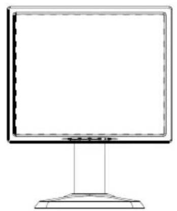
natural_image
Line drawing of a flat-screen computer monitor with a stand (no text or symbols)LCD Display
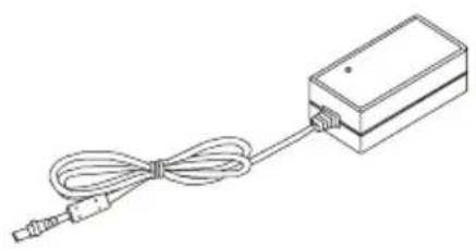
natural_image
Line drawing of a rectangular electronic device with a coiled cable and connector (no text or symbols)Power Adapter
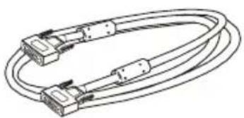
natural_image
Line drawing of a multi-core cable with two connectors (no text or symbols)VGA Signal Cable
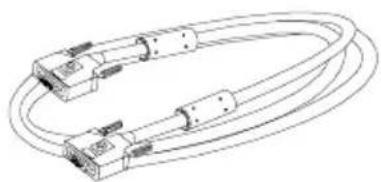
natural_image
Line drawing of a multi-pin cable with connectors and connectors (no text or symbols)DVI-D Cable
natural_image
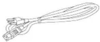
Line drawing of a cable with multiple connectors (no text or symbols)Power Cord
User's Manual
Quick Start Guide
Planar Product
Family CD
CD-ROM for
Pivot software
Installation
Product Overview
◆ Front View
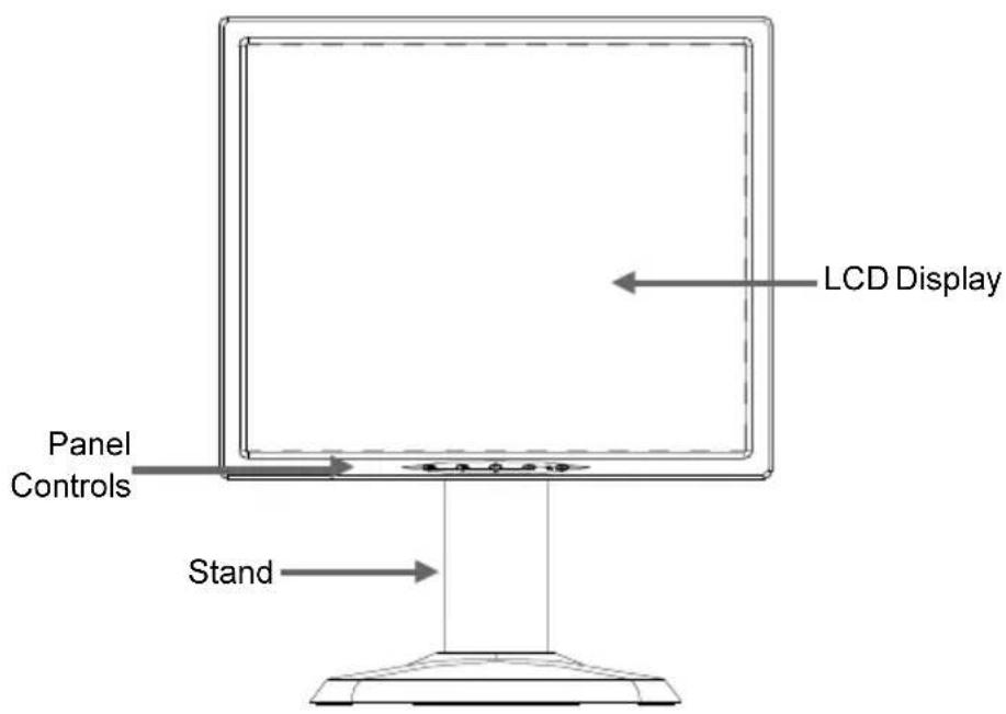
text_image
LCD Display Panel Controls Stand◆Rear View
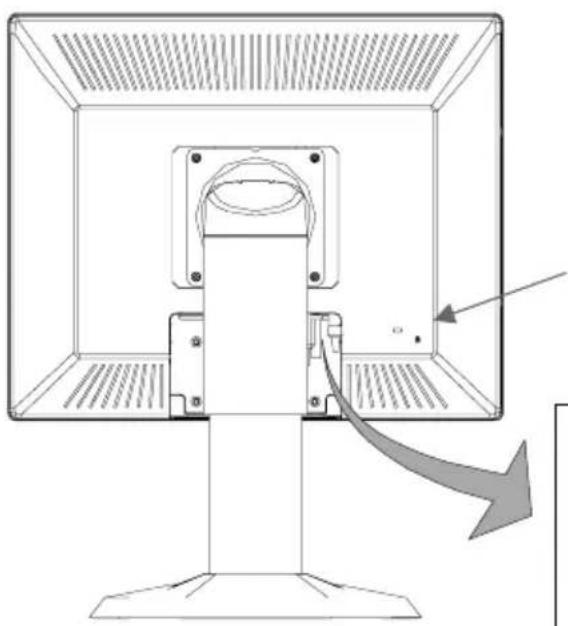
natural_image
Diagram of a computer monitor with an arrow indicating a directional change, showing no text or symbols.Kensington Lock
Connector Ports
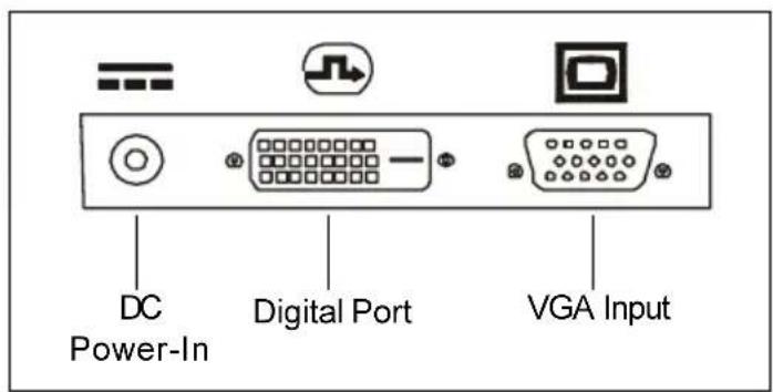
text_image
DC Power-In Digital Port VGA InputVESA Mount on your monitor
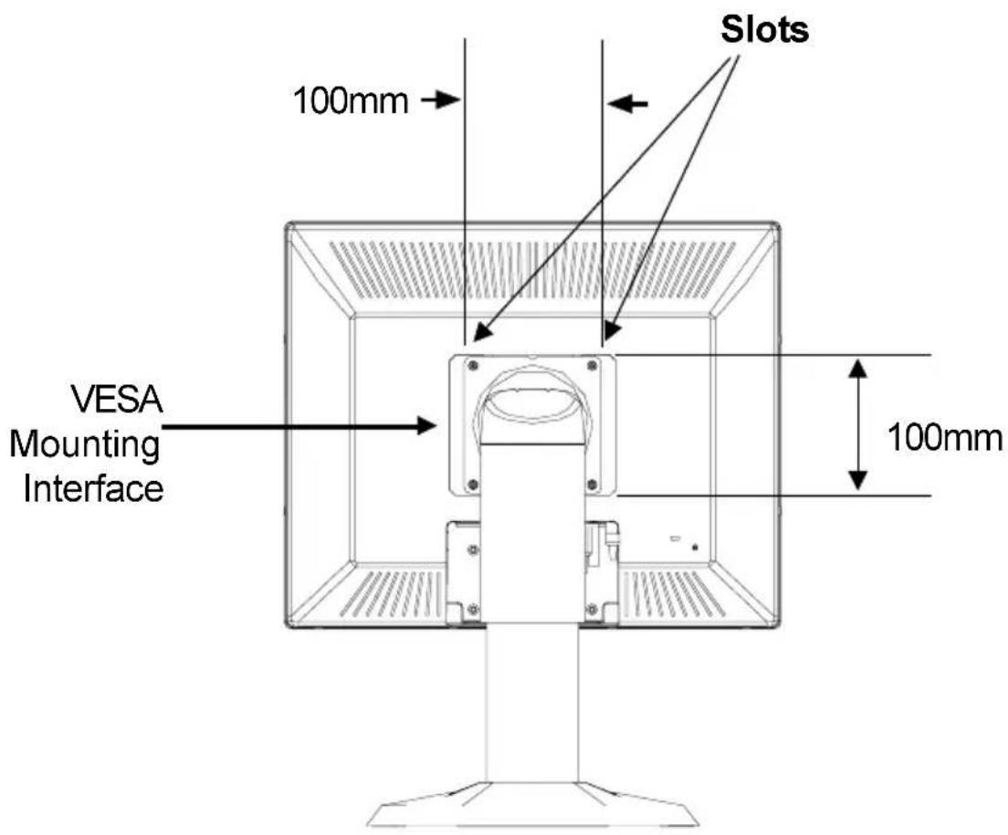
This monitor conforms to the VESA Flat Panel Mounting Physical Mounting Interface Standard which defines a physical mounting interface for flat panel monitors, and corresponding standards for flat panel monitor mounting devices, such as wall and table arms. The VESA mounting interface is located on the back of your monitor.
To mount the monitor on a swing arm or other mounting fixture, follow the instruction included with the mounting fixture to be used.
text_image
Slots 100mm VESA Mounting Interface 100mm
Warning!
Please must select the proper screws!
The depth from plastic back cover to the bottom of the screw hole is 8mm.
The spec is M4 screw.
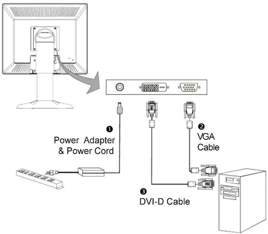
Connecting the Display (Figure 8.1)
To setup this display, please refer to the following figure and procedures.
- Be sure all equipments are off.
- Connect the DC power cord to the power connector; plug one end of the AC power cord into the power adapter, and then the other end into an electrical outlet(1).
- Connect the VGA signal cable from display VGA input connector to the 15-pin connector of your host computer and tighten the screws(②).
- For the PC with DVI digital output: Connect the DVI signal cable to the connector of the display card in your computer; connect the other side to the DVI-D input port of your display. Tighten the screws ^③ .
- Turn on your computer and display.
Note: To ensure the LCD display can work well with your computer, please configure the display mode of your graphic card to make it less than or equal to 1280 x 1024 resolution and make sure timing of the display mode is compatible with the LCD display. We have listed the “Compatibility Modes” of this LCD display in appendices for your reference.
Figure 8.1
flowchart
graph TD
    A["Computer monitor"] -->|Power Adapter & Power Cord| B["Switch"]
    B --> C["Switch 1"]
    B --> D["Switch 2"]
    B --> E["Switch 3"]
    C --> F["DVI-D Cable"]
    D --> F
    E --> F
Vertical Height
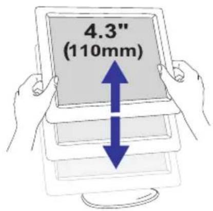
text_image
4.3" (110mm)Portrait/Landscape
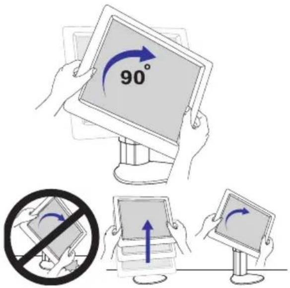
text_image
90°Left to Right Pan
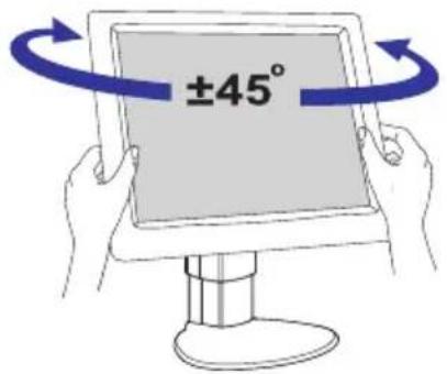
text_image
±45°Front to Back Tilt
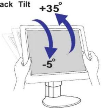
text_image
ack Tilt +35° -5°Remove Monitor

text_image
Prohibition sign with crossed-out tool and blue arrow indicating explosion or explosion
natural_image
Illustration of two hands holding a tablet with a blue upward arrow (no text or symbols)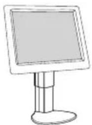
natural_image
Simple line drawing of a flat-screen monitor mounted on a stand (no text or symbols)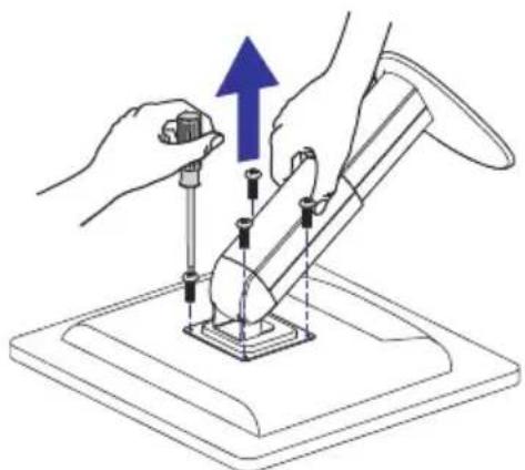
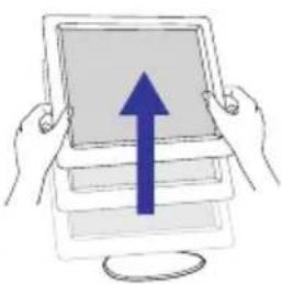
natural_image
Illustration of hands using a tool to adjust or install a mechanical component, with no visible text or symbols.Base may forcefully extend and cause injury Lift Monitor to "Full Up" position before picking up the Base or removing the monitor
User Controls
Front Panel Controls
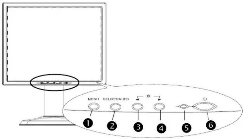
text_image
MENU SELECT/AUTO ① ② ③ ④ ⑤ ⑥| No./ Icon Control | Function | |
| 1 MENU Menu button To pop up the OSD menus. | ||
| 2 SELECT/AUTO | Select/Auto | Select- To select the adjustment items from OSD menus. Auto-To activate the “Auto Adjustment” function to obtain an optimum image. |
| 3 ◀ | Brightness Minus/Minus | Decreases the brightness of the display image.Decreases value of the adjustment items. |
| 4 ▶ | Brightness Plus/Plus 1.Increases the brightness of the display image.Increases value of the adjustment items. | |
| 5 Power LED 1.Green indicates the display is turned on. | ||
| 6 Power Switch | Switches on/off | the power of the LCD display. |
How to Use the OSD Menus
- Press the “M” button to pop up the on-screen menu and to select between the four Main Menus.
- Choose the adjustment items by pressing the "S" button.
- Adjust the value of the adjustment items by pressing the “-” or “+” button.
- Once you don't operate the OSD menus after a pre-set time, the OSD menus will automatically disappear.
On-Screen Display Menus
First OSD Menu:
Auto-Adjustment
Chooses this function to obtain an optimum image.
Contrast
Adjusts the contrast of the display image.
Brightness
Adjusts the brightness of the display image.
Horizontal Position
Changes the horizontal position of the image.
Vertical Position
Changes the vertical position of the image.
Clock
Changes the display data frequency to match the frequency of your graphic card. When you are experiencing vertical flickering bar, use this function to make an adjustment.
Phase
Synchronizes the signal timing of the display to that of the graphic card.
When you are experiencing unstable to flickering image, use this function to make an adjustment.
Second OSD Menu:
Display Mode
Selects this function to demonstrate the display resolution, vertical refresh, and horizontal scan of the current mode.
OSD Off-Time
Adjusts the time period for OSD menu disappear.
Language
Chooses the language you need.
Sharpness
Adjust the sharpness of the image.
Reset
Returns the display parameters of the current mode to its factory default settings.
Third OSD Menu:
Input Select
It allows you to select the type of signal.
Fourth OSD Menu:
Color Setting
Adjusts the color temperature.
Color Adjustment-Red
It allows you to adjust the red color of the display.
Color Adjustment-Green
It allows you to adjust the green color of the display.
Color Adjustment-Blue
It allows you to adjust the blue color of the display.
Appendices
Troubleshooting
If you are experiencing trouble with the LCD display, refer to the follows. If the problem persists, please contact your local dealer or our service center.
Problem: No image appears on screen.
▶ Check that all the I/O and power connectors are correctly and well connected as described in the “Installation” section.
Make sure the pins of the connectors are not crooked or broken.
Problem: Partial image or incorrectly displayed the image.
▶ Check to see if the resolution of your computer is higher than that of the LCD display.
▶ Reconfigure the resolution of your computer to make it less than or equal to 1280 x 1024.
Problem: Image has vertical flickering line bars.
▶ Use “ Frequency ” to make an adjustment.
▶ Check and reconfigure the display mode of the vertical refresh rate of your graphic card to make it compatible with the LCD display.
Problem: Image is unstable and flickering
▶ Use “Tracking” to make an adjustment.
Problem: Image is scrolling
▶ Check and make sure the VGA signal cable (or adapter) is well connected.
▶ Check and reconfigure the display mode of the vertical refresh rate of your graphic card to make it compatible with the LCD display.
Problem: Vague image (characters and graphics)
Use “ Frequency ” to make an adjustment. If this problem still exists, use “Tracking” to make an adjustment.
Warning Signal
Sometimes you probably will see the warning messages from this LCD screen. This means that the LCD display cannot exactly receive the signal from the computer graphic card.
There are three kind of situations may happen. Please check with the connected cables or contact your local dealer for more information.
No Signal
This message means that the LCD display has been powered on but it cannot receive any signal from the computer graphic card. Check all the power switches, power cables, and VGA signal cable.
▶ Going to Sleep
This message means that the LCD display is under the power saving mode. In addition, the LCD display will go to this sleeping mode when experiencing a sudden signal disconnecting problem.
▶ Unsupport Mode
This message means that the signal of the computer graphic card is not compatible with the LCD display. When the signal is not included in the compatibility mode we have listed in the Appendices of this manual, the LCD display will appear this message.
Product Dimensions
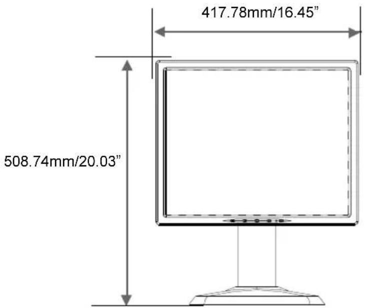
text_image
417.78mm/16.45" 508.74mm/20.03"Front View
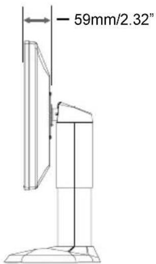
text_image
59mm/2.32"Side View
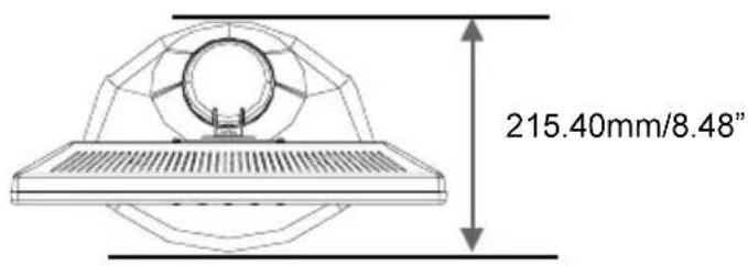
text_image
215.40mm/8.48"Top View
Compatibility Modes
| Mode | Resolution | Frequency (Hz) | H. Frequency (kHz) |
| IBM VGA | 640 x 350 | 70 | 31.5 |
| IBM VGA | 640 x 400 | 70 | 31.5 |
| IBM VGA | 640 x 480 | 60 | 31.5 |
| IBM VGA | 720 x 400 | 70 | 31.5 |
| VESA VGA | 640 x 480 | 72 | 37.9 |
| VESA VGA | 640 x 480 | 75 | 37.5 |
| VESA SVGA | 800 x 600 | 56 | 35.2 |
| VESA SVGA | 800 x 600 | 60 | 37.9 |
| VESA SVGA | 800 x 600 | 72 | 48.1 |
| VESA SVGA | 800 x 600 | 75 | 46.9 |
| VESA XGA | 1024 x 768 | 60 | 48.4 |
| VESA XGA | 1024 x 768 | 70 | 56.5 |
| VESA XGA | 1024 x 768 | 75 | 60.0 |
| VESA SXGA | 1280 x 1024 | 60 | 64.0 |
| VESA SXGA | 1280 x 1024 | 75 | 80 |
| Apple Mac LC | 640 x 480 | 67 | 34.9 |
| Apple Mac II | 640 x 480 | 67 | 35.0 |
| Apple Mac | 832 x 624 | 75 | 49.7 |
| Apple Mac | 1024 x 768 | 75 | 60.2 |
| Sun Micro | 1152 x 900 | 66 | 61.8 |
| Sun Micro | 1152 x 900 | 76 | 71.1 |
Pivot Software Installation
Follows are the procedures for pivot software set up.
- Insert the Pivot Pro CD-ROM into the CD-ROM driver.
- Run the Start_Pivot program and select the pivot option to install portrait displays' software on your computer.
- Restart your computer. To Change orientation, right click anywhere on the desktop and select Rotate 0, 90, 180, or 270 from the menu. Now hold the edges of your display and rotate it.
- Start exploring the benefits of your new portrait monitor. Web pages, E-mail, reports and letters are best viewed in portrait orientation. They can be viewed and edited without the need to scroll the page.
Planar Systems, Inc. Planar Systems, Inc.
Customer Service
24x7 Online TechnoRaliSupportS/ww.planar.com/support
1195 NW Compton Drive
Beaverton, OR 97006-1992
Tel:4866-PLANAR1 (866) 752-6271
Email:PhariarSupport@planar.com
Hours: Hours 5am - 5pm Pacific Time
© 2005 Planar Systems, Inc. 03/05 Planar Systegist, red 03/05 mark of Planar Systems, Inc.
Other brands and names are the property of their respective owners.
Technical information in this document is subject to change without notice.