PS4670 - Monitor Planar - Free user manual and instructions
Find the device manual for free PS4670 Planar in PDF.

User questions about PS4670 Planar
0 question about this device. Answer the ones you know or ask your own.
Ask a new question about this device
Download the instructions for your Monitor in PDF format for free! Find your manual PS4670 - Planar and take your electronic device back in hand. On this page are published all the documents necessary for the use of your device. PS4670 by Planar.
USER MANUAL PS4670 Planar
The information contained in this document is subject to change without notice. This document contains proprietary information that is protected by copyright. All rights are reserved. No part of this document may be reproduced, translated to another language or stored in a retrieval system, or transmitted by any means, electronic, mechanical, photocopying, recording, or otherwise, without prior written permission.
Windows is a registered trademark of Microsoft, Inc.
Other brands or product names are trademarks of their respective holders.
Important Recycle Instruction:

LCD Lamp(s) inside this product contain mercury. This product may contain other electronic waste that can be hazardous if not disposed of properly. Recycle or dispose in accordance with local, state, or federal Laws. For more information on how to recycle your product, please visit WWW.PLANARSYSTEMS.COM/GREEN.
Revision Control
DATE: DESCRIPTION:
May 2011 Document number 020-1128-00 Rev. B.
Table of Contents
Safety Warnings and Precautions ....1
Important Safety Instructions.... 2
Regulatory Compliance Notices 2
FCC Compliance Notice ....2
For Canada....3
Notes on the LCD Panel of This Display.... 3
Copyright 3
Disclaimer 3
Package Contents......4
Parts of the Display and Their Functions......5
Front Panel 5
Rear Panel 5
Input/Output Terminals 6
Remote Control....7
Using the Remote Control 8
Installing Remote Control Batteries....8
Remote Control Usage Tips 8
Battery Safety Notice....8
Setting Up the Display 9
Mounting the Display....9
Connecting Audio/Video Signals 10
Connecting the VGA Input....10
Connecting the Digital Input 11
Connecting the YPbPr Component Video Input.... 12
Connecting the AV and S-Video Inputs.... 13
Connecting External Speakers....14
Connecting Multiple Displays.... 15
Connecting Power.... 16
Basic Operations....17
Turning the Display On or Off.... 17
Locking/Unlocking the Controls.... 17
Control Panel Buttons....17
OSD Menu Function 17
Power On/Off Function 17
Remote Control Functions....17
Switching Input Signals 17
Adjusting Audio Volume Level 17
Table of Contentsii
The OSD (On-Screen Display) Menu 18
OSD Menu Overview.... 18
Operations in the OSD Menu.... 19
Picture Menu....20
Adjusting the Contrast 20
Adjusting the Brightness....20
Sound Menu....21
Option Menu.... 22
Setting Menu 23
Product Information 25
Specifications 25
Supported Input Signal Resolution 29
Supported PIP Input Signal Combination.... 30
Supported Signal Source and Resolution in PIP Mode .... 31
Troubleshooting.... 40
Safety Warnings and Precautions

text_image
CAUTION RISK OF ELECTRIC SHOCK DO NOT OPENCAUTION: TO REDUCE THE RISK OF ELECTRIC SHOCK, DO NOT REMOVE COVER (OR BACK). NO USER-SERVICEABLE PARTS INSIDE. REFER SERVICING TO QUALIFIED SERVICE PERSONNEL.

The lightning flash with arrowhead symbol, within an equilateral triangle, is intended to alert the user to the presence of uninsulated "dangerous voltage" within the product's enclosure that may be of sufficient magnitude to constitute a risk of electric shock to persons.

The exclamation point within an equilateral triangle is intended to alert the user to the presence of important operating and maintenance (servicing) instructions in the literature accompanying the appliance.
THIS EQUIPMENT MUST BE GROUNDED
To ensure safe operation, the three-pin plug must be insert standard three-pin power outlet which is effectively grounded through normal household wiring. Extension cords used with the equipment must have three cores and be correctly wired to provide connection to the ground. Wrongly wired extension cords are a major cause of fatalities.
The fact that the equipment operates satisfactorily does not imply that the power outlet is grounded or that the installation is completely safe. For your safety, if you are in any doubt about the effective grounding of the power outlet, please consult a qualified electrician.
- The mains plug of the power supply cord shall remain readily operable. The AC receptacle (mains socket outlet) shall be installed near the equipment and shall be easily accessible. To completely disconnect this equipment from the AC mains, disconnect the power cord plug from the AC receptacle.
- Do not place this display on an uneven, sloping or unstable surface (such as a trolley) where it may fall and cause damage to itself or others.
- Do not place this display near water, like a spa or pool, or in a position which will allow the splashing or spraying of water onto the display, like in front of an open window where rain water may enter.
- Do not install this display in a confined space without proper ventilation and air circulation, such as in a closed cabinet. Allow proper space around the display for dissipating heat inside. Do not block any openings and vents on the display. Overheating may result in hazards and electric shock.
- Installation of this display should only be performed by a qualified technician. Failure to install this display properly may cause injuries and damages to the personnels and the display itself. Check the installation regularly and maintain the display periodically to ensure the best working condition.
- Use only the accessories approved or recommended by the manufacturer to mount this display. Using wrong or unsuitable accessories may cause the display to fall and result in serious personal injuries. Make sure that the surface and fixing points are strong enough to sustain the weight of the display.
- To reduce the risk of electric shock, do not remove covers. No user serviceable parts inside. Refer servicing to qualified service personnel.
Important Safety Instructions
-
Read these instructions.
-
Keep these instructions.
-
Heed all warnings.
-
Follow all instructions.
-
Do not use this apparatus near water.
-
Clean only with dry cloth.
-
Do not block any ventilation openings. Install in accordance with the manufacturer's instructions.
-
Do not install near any heat sources such as radiators, heat registers, stoves, or other apparatus (including amplifiers) that produce heat.
-
Do not defeat the safety purpose of the polarized or grounding-type plug. A polarized plug has two blades with one wider than the other. A grounding-type plug has two blades and a third grounding prong. The wide blade or the third prong are provided for your safety. If the provided plug does not fit into your outlet, consult an electrician for replacement of the obsolete outlet.
-
Protect the power cord from being walked on or pinched particularly at plugs, convenience receptacles, and the point where they exit from the apparatus.
-
Only use attachments/accessories specified by the manufacturer.
-
Use only with the cart, stand, tripod, bracket, or table specified by the manufacturer, or sold with the apparatus. When a cart is used, use caution when moving the cart/apparatus combination to avoid injury from tip-over.
-
Unplug this apparatus during lightning storms or when unused for long periods of time.
-
Refer all servicing to qualified service personnel. Servicing is required when the apparatus has been damaged in any way, such as power-supply cord or plug is damaged, liquid has been spilled or objects have fallen into the apparatus, the apparatus has been exposed to rain or moisture, does not operate normally, or has been dropped.

Regulatory Compliance Notices
FCC Compliance Notice
This device complies with part 15 of FCC Rules. Operation is subject to the following two conditions: (1) this device may not cause harmful interference, and (2) this device must accept any interference received, including interference that may cause undesired operation.
This equipment has been tested and found to comply with the limits for a Class B digital device, pursuant to part 15 of the FCC Rules. These limits are designed to provide reasonable protection against harmful interference in a residential installation. This equipment generates, uses, and can radiate radio frequency energy, and if not installed and used in accordance with the instructions, may cause harmful interference to radio communications. However, there is no guarantee that interference will not occur in a particular installation. If this equipment does cause harmful interference to radio or television reception, which can be determined by turning the equipment off and on, the user is encouraged to try to correct the interference by one or more of the following measures:
- Reorient or relocate the receiving antenna.
- Increase the separation between the equipment and receiver.
- Connect the equipment into an outlet on a circuit different from that to which the receiver is connected.
- Consult the dealer or an experienced radio/TV technician for help.
Warning: You are cautioned that changes or modifications not expressly approved by the party responsible for compliance could void your authority to operate the equipment.
For Canada
- This Class B digital apparatus complies with Canadian ICES-003.
Notes on the LCD Panel of This Display
- The Liquid Crystal Display (LCD) panel of this display has a very thin protective layer of glass which is liable to marking or scratching, and cracking if struck or pressured. The liquid crystal substrate is also liable to damage under excessive force or extreme temperatures. Please handle with care.
- The response time and brightness of the LCD panel may vary with the ambient temperature.
- Avoid placing the display in direct sun or where direct sun or spot lighting will shine onto the LCD panel, as the heat may damage the panel and the external casing of the display, and the bright light will make viewing the display more difficult than necessary.
- The LCD panel consists of individual pixels to display images and is manufactured according to the design specifications. While 99.9% of these pixels work normally, 0.01% of the pixels may remain constantly lit (in red, blue or green) or unlit. This is a technical limitation of the LCD technology and is not a defect.
- LCD screens, like plasma (PDP) and conventional CRT (Cathode Ray Tube) screens, are also susceptible to 'screen burn-in' or 'image retention' which can be found on the screen as visible fixed lines and shades. To avoid such damage to the screen, avoid displaying still images (like On-Screen Display menus, TV station logos, fixed/inactive text or icons) for more than two hours. Change the aspect ratio from time to time. Fill the entire screen with the image and eliminate the black bars whenever possible. Avoid displaying images in 4:3 aspect ratio over a long period of time, otherwise there may be visible burn marks on the screen as two vertical lines. Image retention issues are not covered under warranty, see standard warranty terms and conditions for details. For optimal performance, we suggest turning off the backlight power on the display for 8 hours per day.
Copyright
Copyright 2011. All rights reserved. No part of this publication may be reproduced, transmitted, transcribed, stored in a retrieval system or translated into any language or computer language, in any form or by any means, electronic, mechanical, magnetic, optical, chemical, manual or otherwise, without the prior written permission of the manufacturer.
Disclaimer
The manufacturer makes no representations or warranties, either expressed or implied, with respect to the contents of this document. The manufacturer reserves the right to revise this publication and to make changes from time to time in the contents thereof without obligation to notify any person of such revision or changes.
Package Contents
Open the sales package and check the contents. If any item is missing or damaged, please contact your dealer immediately.
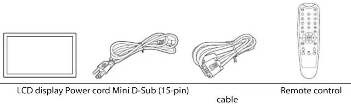
LCD display Power cord Mini D-Sub (15-pin)
cable
Remote control


AAA batteries Quick start guide
Notes:
- The type of power cord supplied may differ from that illustrated depending on your region of purchase.
- Before discarding the package, check that you haven't left any accessories inside the box.
- Dispose of packaging materials wisely. You can recycle the cardboard carton. Consider storing the package (if possible) for future transport of the display.
- Do not leave plastic bags within reach of young children or babies.
Parts of the Display and Their Functions
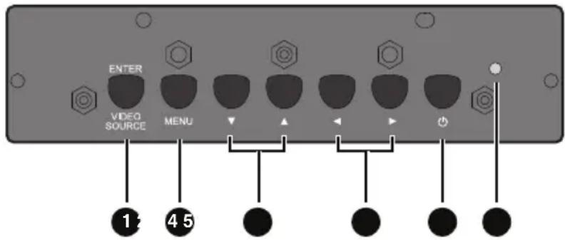
Front Panel
No. Name Description
| 1 | Remote control sensor / Ambient light sensor / Power indicator | • Receives command signals from the remote control.• Detects ambient lighting conditions around the display and adjusts screen brightness automatically when the Ambient Light Sensor function is activated.• Indicates the operating status of the display:- Lights up green when the power is turned on.- Lights up red when the display is turned off.- Lights up red when the display is in Standby Eco mode.- Flashes red when the display is in Standby Standard mode.- Off when the main power is turned off. |
Rear Panel
text_image
ENTER VIDEO SOURCE MENU 1 4 5No. Name Description
| 1 | ENTER/VIDEO SOURCE | • Selects a video source.• Confirms your selection or enters a submenu in the On-Screen Display (OSD) menu. |
| 2 | MENU | • Opens the OSD menu.• Returns to a previous menu or exits the OSD menu. |
| 3 | ▼ / ▲ | Scrolls through settings and options in the OSD menu. |
| 4 | ◀ / ▶ | Scrolls through settings and options in the OSD menu. |
| 5 | Power button Turns on the display or puts it in standby mode. | |
| 6 | Power indicator | Indicates the power status of the display:- Lights up green when the power is turned on.- Lights up red when the display is turned off.- Lights up red when the display is in Standby Eco mode.- Flashes red when the display is in Standby Standard mode.- Off when the main power is turned off. |
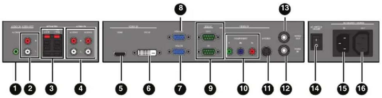
Input/Output Terminals
text_image
Diagram of a device rear panel with labeled ports and connectors, numbered 1 to 16.No. Name Description
| 1 | AUDIO IN (AUDIO1) Receives audio signals from an external device (such as a computer). | |
| 2 | AUDIO OUT (L/R) | Outputs audio signals from an audio or HDMI input source to an external device. |
| 3 | SPEAKERS (L/R) | Outputs audio signals from an audio or HDMI input source to external speakers. |
| 4 | AUDIO IN (AUDIO2/AUDIO3) | Receives audio signals from an external device (such as a VCR or DVD player). |
| 5 | VIDEO IN (HDMI) | Receives HDMI signals from an external device (such as a Blu-ray disc player). |
| 6 | VIDEO IN (DVI-D) Receives DVI signals from an external device (such as a computer). | |
| 7 | VGA IN | Receives analog RGB signals from an external device (such as a computer). |
| 8 | VGA OUT | Outputs analog RGB signals from the VGA IN input to another display. |
| 9 | RS232C-IN/OUT | For external control and multi-display operation.RS232C-IN: receives control signals from a computer or another display.RS232C-OUT: outputs control signals from the RS232C-IN input to another display. |
| 10 | VIDEO IN (COMPONENT) | Receives component video (YPbPr) signals from an external device (such as a DVD player, HDTV device or Laser disc player). |
| 11 | VIDEO IN (S-VIDEO) | Receives S-Video signals from an external device (such as a VCR or DVD player). |
| 12 | VIDEO IN | Receives composite video signals from an external device (such as a VCR or DVD player). |
| 13 | VIDEO OUT | Outputs composite video signals from the VIDEO IN input to another display. |
| 14 | AC SWITCH ON/OFF Turns on or off the main power. | |
| 15 | AC IN Connects to a power outlet via the supplied power cord. | |
| 16 | AC OUT Relays the AC power from the AC IN jack to another display. | |
Note:
Connector locations on the control panel may differ depending on the model.
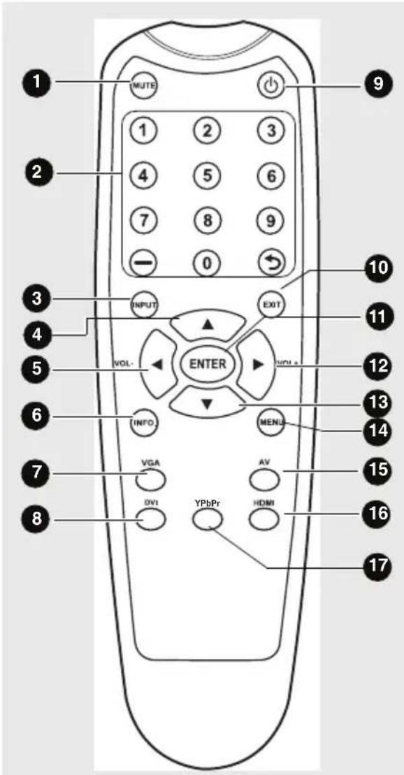
Remote Control
text_image
1 MUTE 2 1 2 3 4 5 6 7 8 9 - 0 3 INPUT VOL- ENTER EXIT 10 11 12 13 14 6 INFO MENU VGA AV DVI HDMI 15 16 171 MUTE
Turns on or off the mute function.
2 Numeric buttons
No function.
3 INPUT
Selects an input source.
4
Scrolls through settings and options in the OSD menu.
5 / VOL-
- Scrolls through settings and options in the OSD menu.
• Turns down the volume.
6 INFO.
Shows the current input source and resolution.
7 VGA
Selects the VGA input source.
8 DVI
Selects the DVI input source.
9 Power
Turns on the display or puts it in standby mode.
10 EXIT
Returns to a previous menu or closes the OSD menu.
11 ENTER
Confirms your selection or save changes.
12 ▶ / VOL+
- Scrolls through settings and options in the OSD menu.
• Turns up the volume.
13
Scrolls through settings and options in the OSD menu.
14 MENU
Opens or closes the OSD menu.
15 AV
Selects the AV input source.
16 HDMI
Selects the HDMI input source.
17 YPbPr
Selects the YPbPr input source.
Using the Remote Control
Installing Remote Control Batteries
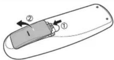
text_image
Diagram of a remote control device with labeled parts and directional arrows indicating movement or force- Open the remote control battery compartment cover.
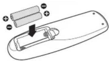
natural_image
Diagram of a remote control with battery and indicator lights (no text or symbols)- Insert the supplied batteries ensuring that the positive and negative marked battery terminals match the (+) and (-) marks in the battery compartment.
Note:
The supplied batteries are provided for your convenience so that you can operate the display straight away. You should replace them as soon as possible.
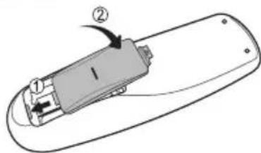
text_image
Diagram of a remote control device with labeled parts and directional arrows indicating movement or force- Refit the battery compartment cover.
Remote Control Usage Tips
- Point and aim the top front of the remote control directly at the display's remote control sensor window when you press the buttons.
- The remote control must be held at an angle within 45 degrees of the display's remote control sensor window to function correctly. The distance between the remote control and the sensors should not exceed 10 meters (32.8 feet).
- Do not let the remote control become wet or place it in humid environments (like bathrooms).
- If the display's remote control sensor window is exposed to direct sunlight or strong light, the remote control may not operate properly. In this situation, change the light source, readjust the angle of the display or operate the remote control from a location closer to display's remote control sensor window.
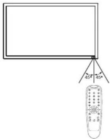
text_image
45° 45°Battery Safety Notice
Using wrong types of batteries may cause chemical leaks and/or explosion. Please pay attention to the following notes:
• Always ensure that the batteries are inserted with the positive and negative terminals in the correct directions as shown in the battery compartment.
- Different types of batteries have different characteristics. Do not mix different types. Do not mix old and new batteries. Mixing old and new batteries will shorten battery life and/or cause chemical leaks from the old batteries.
- When batteries fail to function, replace them immediately.
- Chemical leaks from batteries may cause skin irritation. If any chemical matter seeps out of the batteries, wipe it up immediately with a dry cloth.
Setting Up the Display
Mounting the Display
You can install the display on a vertical surface with a suitable wall mounting bracket or on a horizontal surface with the optional desktop stands. Please pay attention to the following notes during installation:
- This display should be installed by at least two adult persons. Attempting to install this display by only one person may result in danger and injuries.
- Refer the installation to qualified technicians. Improper installation may cause the display to fall or malfunction.
VESA mounts are used to secure the PS-Series for display. The PS-Series displays can be installed using a variety of VESA mounts available through Planar. If you do not have a VESA mount and would like to purchase one, contact Planar.
If you purchased a VESA mount, you should have received a separate box with mounting supplies and an installation manual. Follow these instructions carefully.
Keep in mind the following general installation guidelines:
- Screw length is crucial and will vary depending on the type of mount you use. Total screw length will include the penetration length plus the length required by the type of VESA mount in use.
Caution: Shorter screws will result in insufficient mounting length and longer screws could puncture parts inside the display.
- Prior to installation, make sure you know where all of the mounting points are located.
- Follow all safety precautions outlined in the VESA Installation manual.
- Verify the parts received with the list shown in the VESA Installation manual.
Notes:
- To maintain proper ventilation, keep at least 10mm of clear space from wall to rear cover of the display.
- The power connector should be positioned at the bottom of other connectors when you rotate the display.
- Please consult a professional technician for wall mount installations. The manufacturer accepts no liability for installations not performed by a professional technician.
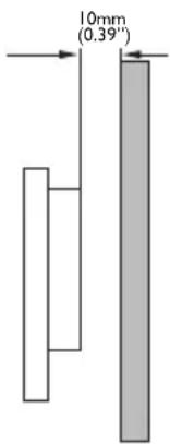
text_image
10mm (0.39")Connecting Audio/Video Signals
Pay attention to the following notes when you connect cables:
- Please turn off all devices.
- Familiarize yourself with the audio/video ports on the display and the devices you want to use. Be aware that incorrect connections may adversely affect picture quality.
- Do not remove cables from the ports by pulling the cable itself. Always grasp and pull the connectors at the end of the cable.
- Ensure that all cables are fully inserted and firmly seated.
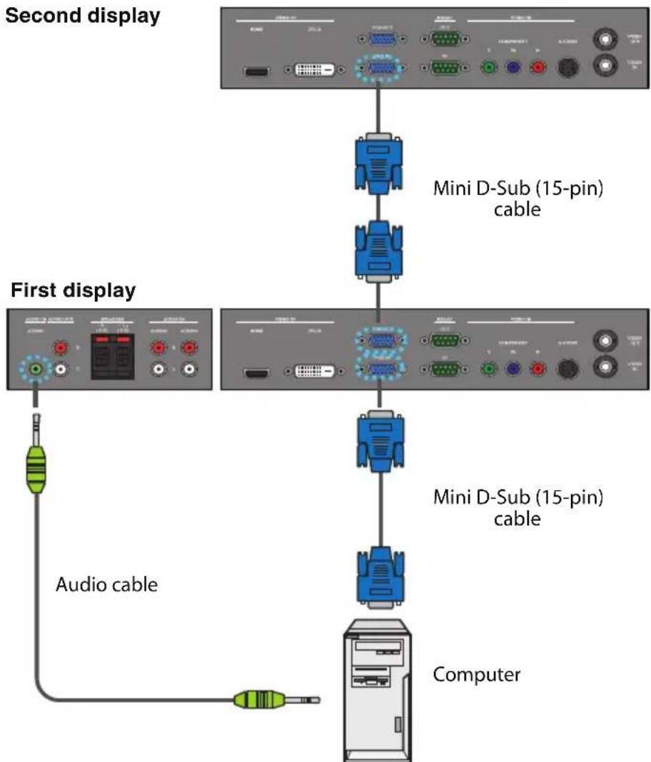
Connecting the VGA Input
- Connect the VGA IN jack on the display to the VGA output jack on a computer using a Mini D-Sub (15-pin) cable.
- Connect the computer's audio output jack to the AUDIO IN jack on the display using a suitable audio cable.
- If a second display is used, connect the VGA OUT jack on the first display to the VGA IN jack on the second display using a Mini D-Sub (15-pin) cable. This relays the VGA input signal from the first display to the second one.
- To view images from this input, press the VGA button on the remote control.
flowchart
graph TD
    A["Second display"] --> B["Mini D-Sub (15-pin) cable"]
    B --> C["First display"]
    C --> D["Mini D-Sub (15-pin) cable"]
    D --> E["Computer"]
    C --> F["Audio cable"]
*The audio cable is not supplied and should be purchased separately.
Note:
Connector locations on the control panel may differ depending on the model.
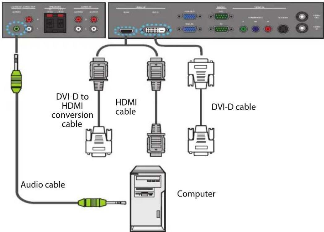
Connecting the Digital Input
- Connect the VIDEO IN (DVI-D) jack on the display to the DVI-D output jack on a computer using a DVI-D cable. If the computer has an HDMI output jack, connect the computer's HDMI output jack to the VIDEO IN (HDMI) input jack on the display using an HDMI cable or a DVI-D to HDMI conversion cable.
- Connect the computer's audio output jack to the AUDIO IN jack on the display using a suitable audio cable.
- To view video image from this input, press theDVI or HDMI button on the remote control.
flowchart
graph TD
    A["Computer"] -->|Audio cable| B["HDMA conversion cable"]
    A -->|DVI-D cable| C["DVI-D to HDMI cable"]
    A -->|DVI-D| D["Computer"]
*The cables are not supplied and should be purchased separately.
Note: Connector locations on the control panel may differ depending on the model.
Connecting the YPbPr Component Video Input
- Connect the VIDEO IN (COMPONENT) jacks on the display to the component output jacks on an A/V device (such as a VCR or DVD player) using a component video cable.
- Connect the DVD player's audio output jacks to the AUDIO IN (AUDIO2 or AUDIO3) jacks on the display using a suitable audio cable.
- To view video image from this input, press the YPbPr button on the remote control.
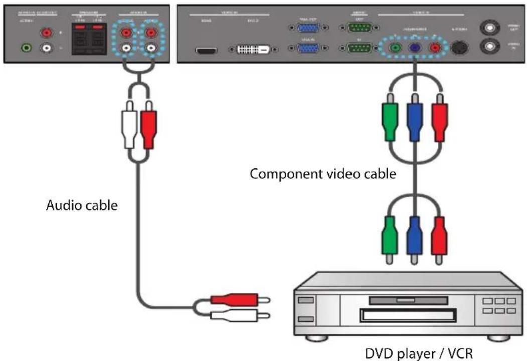
text_image
Audio cable Component video cable DVD player / VCR*The cables are not supplied and should be purchased separately.
Note:
Connector locations on the control panel may differ depending on the model.
Connecting the AV and S-Video Inputs
-
Connect the VIDEO IN (S-VIDEO) or VIDEO IN jack on the display to the output jack on an A/V device (such as a VCR) using an appropriate video cable.
-
Connect the VCR's audio output jacks to the AUDIO IN (AUDIO2 or AUDIO3) jacks on the display using a suitable audio cable.
-
If a second display is used, connect the VIDEO-OUT jack on the first display to the VIDEO IN jack on the second display using an AV cable. This relays the input signal from the first display to the second one.
-
To view video image from this input, press the AV button on the remote control for the AV signal, or press the INPUT button repeatedly for the S-Video signal.
Second display
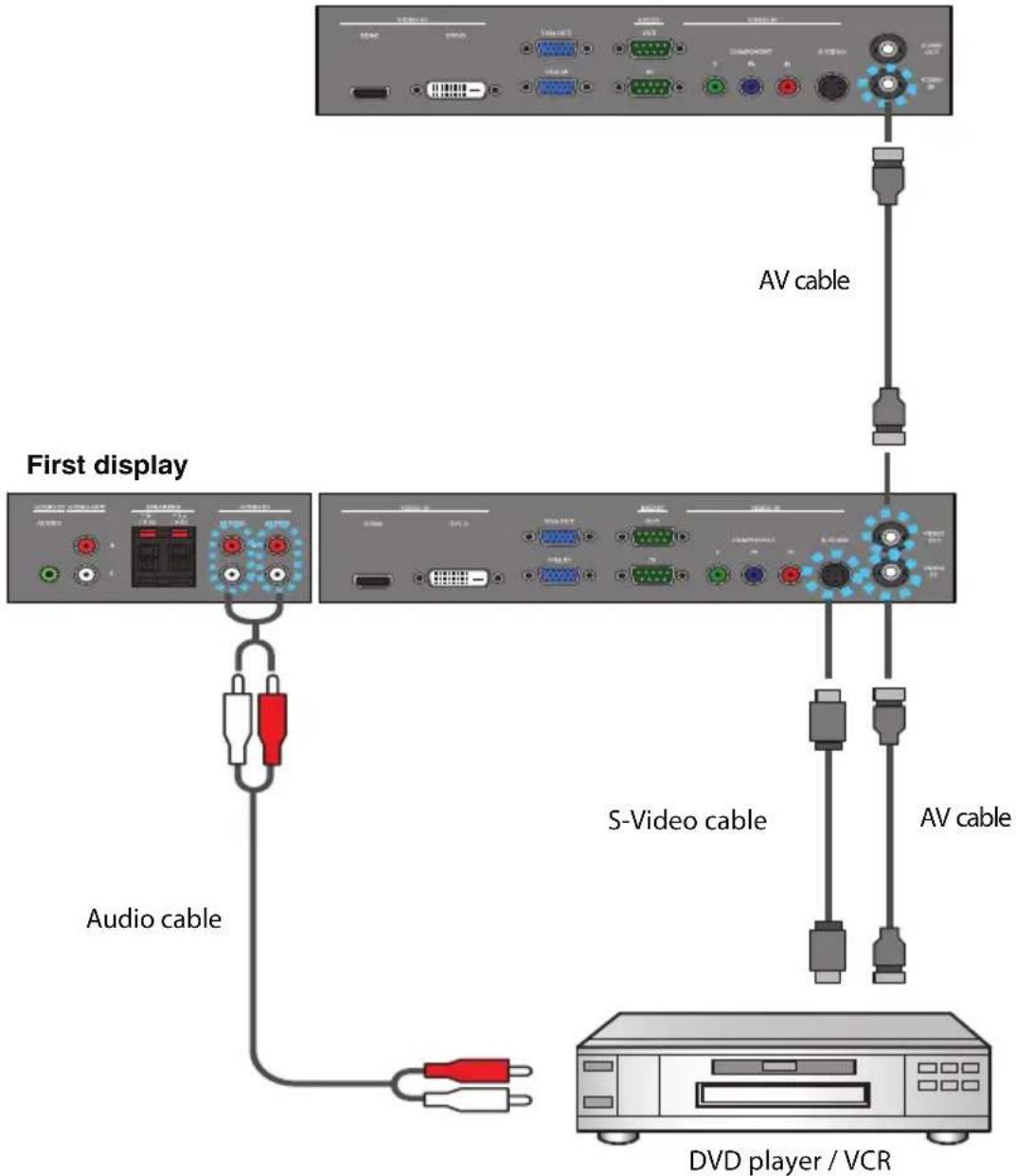
text_image
First display AV cable S-Video cable AV cable Audio cable DVD player / VCR*The cables are not supplied and should be purchased separately.
Note:
Connector locations on the control panel may differ depending on the model.
Connecting External Speakers
The built-in amplifier on the display allows you to output audio signals through external speakers. Connect external speakers to the SPEAKERS jacks on the display.
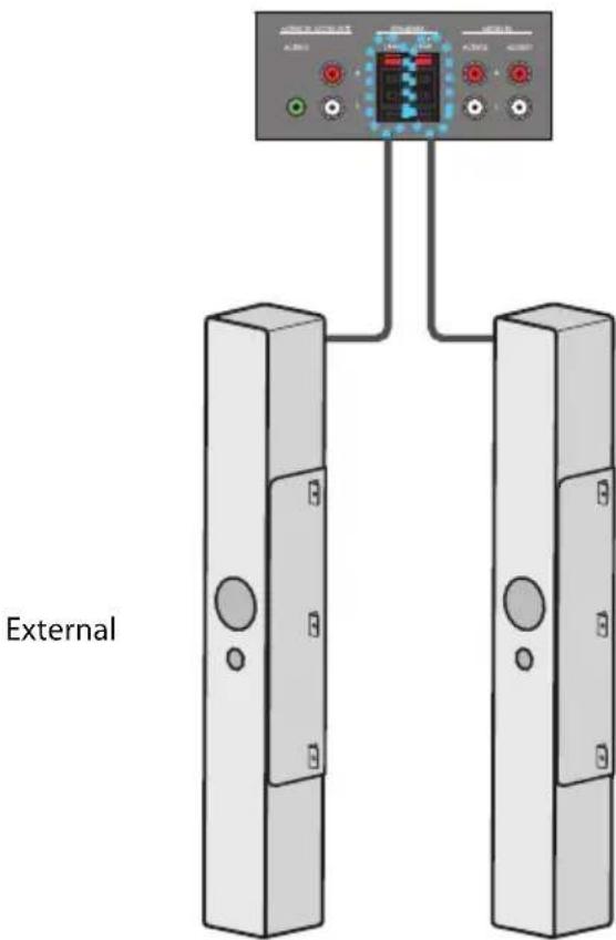
text_image
ExternalNote:
You can use the remote control or the control panel on the display to adjust the volume.
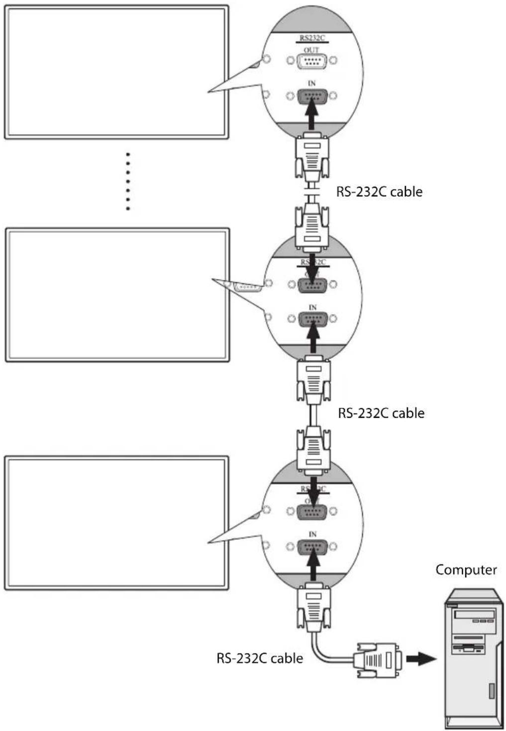
Connecting Multiple Displays
With the RS232C-IN/OUT interfaces, you can connect multiple displays serially (daisy chain) to a computer for management. The number of displays you can connect serially depends on the resolution of the input signal you use.
flowchart
graph TD
    A["Input"] --> B["RS-232C OUT"]
    B --> C["RS-232C cable"]
    C --> D["RS-232C IN"]
    D --> E["RS-232C cable"]
    E --> F["RS-232C OUT"]
    F --> G["RS-232C cable"]
    G --> H["Computer"]
    style A fill:#f9f,stroke:#333
    style B fill:#ccf,stroke:#333
    style C fill:#cfc,stroke:#333
    style D fill:#fcc,stroke:#333
    style E fill:#cff,stroke:#333
    style F fill:#ffc,stroke:#333
    style G fill:#cfc,stroke:#333
    style H fill:#fcc,stroke:#333
Note:
This function requires an RS-232C port equipped computer with the display management software installed.
Connecting Power
- Plug one end of the power cord into the AC IN jack on the display and the other end into an appropriate power outlet (if the outlet is switched, turn on the switch).
- Press the power switch to turn on the main power. The display will enter standby mode and the power indicator will light up amber.
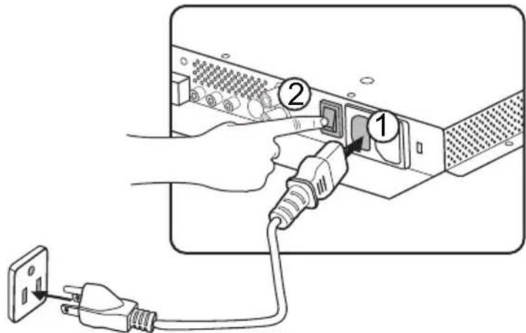
text_image
Diagram showing connection between a device with labeled components: plug, socket, and power outletNotes:
• The supplied power cord is suitable for use with 110-240V AC power only.
• The power cord and outlet illustrated may differ from the ones used in your region.
- Only use an appropriate power cord for your region. Never use a power cord which appears damaged or frayed, or change the plug type on the power cord.
- Be aware of the power loading when you use extension cords or multiple outlet power boards.
- There are no user serviceable parts in this display. Never unscrew or remove any covers. There are dangerous voltages inside the display. Turn off the power and unplug the power cord if you intend to move the display.
Basic Operations
Turning the Display On or Off
To turn on or off the display, press the power button on the display's control panel or on the remote control.
Notes:
- The display's standby mode still consumes a very small amount of power. To completely cut off the power supply, press the power switch to trun off the main power.
- The display follows the VESA approved DPM Power Management function. The power management function is an energy saving feature that automatically reduces the display's power consumption when the keyboard or the mouse has not been used for a fixed period.
text_image
MUTE ① ② ③ ④ ⑤ ⑥ ⑦ ⑧ ⑨Locking/Unlocking the Controls
The display's controls can be locked and unlocked to prevent unwanted or accidental operations. These commands are used for locking and unlocking.
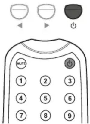
Control Panel Buttons
Press and hold ◀ and ▶ simultaneously for 5 seconds. Once locked, the control panel buttons do not function unless unlocked.
OSD Menu Function
Press and hold ▲ and ▼ simultaneously for 5 seconds. Once locked, the MENU button on the control panel does not function, and the OSD menu can not be used unless unlocked.
Power On/Off Function
Press and hold MENU and ◀ for 5 seconds. Once locked, the power button on the control panel does not function, and current power on/off status will be kept unless unlocked.
Remote Control Functions
Press and hold MENU and ▶ for 5 seconds. Once locked, the display does not respond to any remote control operations unless unlocked.
Switching Input Signals
Press the VGA, DVI, HDMI, YPbPr, AV and INPUT buttons on the remote control or the INPUT button on the control panel to select an input signal.
Adjusting Audio Volume Level
Press ▲/▼ on the control panel or VOL+/VOL- on the remote control to adjust the volume.
The OSD (On-Screen Display) Menu
OSD Menu Overview
| Menu name Options/functions See page | ||
| Picture | Picture ModeContrastBrightnessColorTintSharpnessBacklightDCRColor TempInput Resolution | 20 |
| Sound | VolumeMuteAudio SourceSpeaker | 21 |
| Option | Aspect ratioPIPVideo SourceAuto AdjustmentClock FrequencyPhaseH PositionV PositionAmbient Light SensorAuto Detection | 22 |
| Setting | LanguageOverscanScheduleDisplay WallPower SaveSet Monitor IDImage RetentionAuto AdjustmentOSD RotationAdvanced | 23 |
Note:
Some options are only available when a certain input signal source is selected.
Operations in the OSD Menu
| Using the control panel buttons Using the remote control | |
1. Press MENU to open the OSD menu.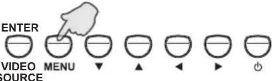 | 1. Press MENU to open the OSD menu.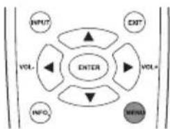 |
2. Press ▲ or ▼ to select an item.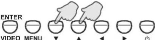 SOURCE SOURCE | 2. Press ▲ or ▼ to select an item.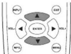 |
3. Press ENTER/VIDEO SOURCE to confirm selections.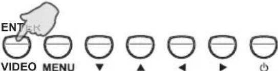 SOURCE SOURCE | 3. Press ENTER to confirm selections.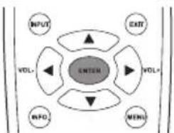 |
4. Press ▲ or ▼ to select a feature and press ◀ or ▶ to adjust settings. Press ENTER/VIDEO SOURCE to save changes.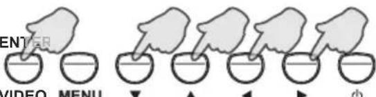 SOURCE SOURCE | 4. Press ▲ and ▼ to select a feature and press ◀ or ▶ to adjust settings. Press ENTER to confirm changes.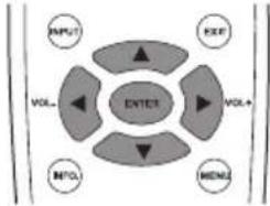 |
5. Press MENU to close the OSD menu.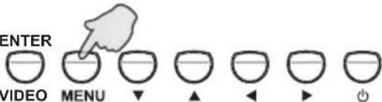 SOURCE SOURCE | 5. Press EXIT to close the OSD menu.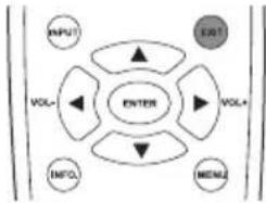 |
Picture Menu
Picture
 | Picture Mode Standard | |
| Contrast 88 | ||
| Brightness 43 | ||
 | Color | 55 |
| Tint | 50 | |
 | Sharpness | 5 |
| Backlight | 5 | |
| DCR | OFF | |
 | Color temp. | 9300°K |
| Input Resolution | Auto |
| Name Description | |
| Picture Mode Sets the display mode. | |
| Contrast Adjusts the image contrast when Picture Mode is set to User. | |
| Brightness Adjusts the image brightness when Picture Mode is set to User. | |
| Color Adjusts the color intensity when Picture Mode is set to User. | |
| Tint Adjusts the color tint when Picture Mode is set to User. | |
| Sharpness Adjusts the image sharpness when Picture Mode is set to User. | |
| Backlight | Adjusts the backlight intensity for the screen.Note: This feature is not available if the Ambient Light Sensor function is set to HIGH or LOW. |
| DCR | Turns the DCR function on or off. This feature enhances image contrast for dark scenes.Note: This feature is not available if the Ambient Light Sensor function is set to HIGH or LOW. |
| Color Temp Adjusts the color temperature. | |
| Input Resolution | Sets the VGA input resolution. This is only required when the display cannot detect the resolution correctly. |
Adjusting the Contrast
- Set the contrast to the highest level.
- Gradually decrease the contrast level until you reach the point where the details in the bright areas of the image can be seen clearly. Do not further decrease the contrast level to avoid losing the saturation of colors.
Adjusting the Brightness
- Set the brightness to the lowest level.
- Gradually increase the brightness level until you reach the point where the details in the dark areas of the image can be seen clearly. Do not further increase the brightness level to avoid the black areas from looking grayish.
Sound Menu
Sound

text_image
Volume 8 Mute OFF Audio Source Audio 1 Speaker External :Move Enter :Input Exit :ExitName Description
Volume Adjusts the volume.
Mute Turns the mute function on or off.
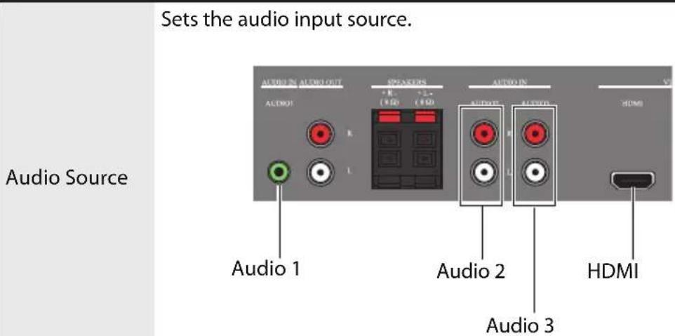
text_image
Sets the audio input source. Audio Source AUDIO IN AUDIO INPUT AUDIO IN AUDIO OUTPUT AUDIO IN AUDIO IN AUDIO IN AUDIO IN AUDIO IN AUDIO IN AUDIO IN AUDIO IN AUDIO IN AUDIO IN AUDIO IN AUDIO IN AUDIO IN AUDIO IN AUDIO IN AUDIO IN AUDIO IN AUDIO IN AUDIO IN AUDIO IN AUDIO IN AUDIO IN AUDIO IN AUDIO IN AUDIO IN AUDIO IN AUDIO IN AUDIO IN AUDIO IN AUDIO IN AUDIO IN AUDIO IN AUDIO IN AUDIO IN| Speaker | Sets the audio source. External: Selects the audio output source from SPEAKERS on the rear connector panel. Line-Out: Selects the audio output source from AUDIO OUT on the rear connector panel. Internal: Select the audio input source from AUDIO IN on the rear connector panel. (PS4200 only) |
Option Menu
Option
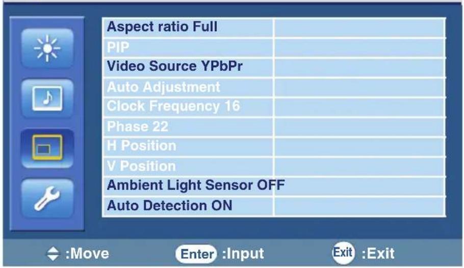
text_image
Aspect ratio Full PIP Video Source YPbPr Auto Adjustment Clock Frequency 16 Phase 22 H Position V Position Ambient Light Sensor OFF Auto Detection ON :Move Enter :Input Exit :Exit| Name Description | |
| Aspect ratio | Displays the input image in its original aspect ratio (when Original is selected) or forces the display to fill the input image on the entire display area (when Full is selected). |
| PIP (Picture in Picture) | ON/OFF:Turns on or off the PIP function.Main Input:Sets an input source for the main picture.Sub Input:Sets an input source for the sub picture.PIP Size:Changes the size of the sub picture.PIP Position:Changes the position of the sub picture.Notes:This feature is not available for AV and S-Video inputs.PIP is not available for all signal source combinations. See "Supported PIP Input Signal Combination" on page 30 for more information on supported combinations.In PIP mode, only sounds from the Main Input picture will be available. |
| Video Source Sets the video input source. | |
| Auto Adjustment Automatically optimizes image display for the VGA input. | |
| Clock Frequency Adjusts the clock frequency of the VGA or YPbPr input image. | |
| Phase Adjusts the phase of the VGA or YPbPr input image. | |
| H Position Adjusts the horizontal position of the VGA input image. | |
| V Position Adjusts the vertical position of the VGA input image. | |
| Ambient Light Sensor | Adjusts the ambient light sensitivity around the display. |
| Auto Detection Automatically detects available input sources. | |
Note: The adjustment of the Clock Frequency, Phase, H Position and V Position settings is only required when the Auto Adjustment function does not work perfectly on certain input signals.
Setting Menu
Setting
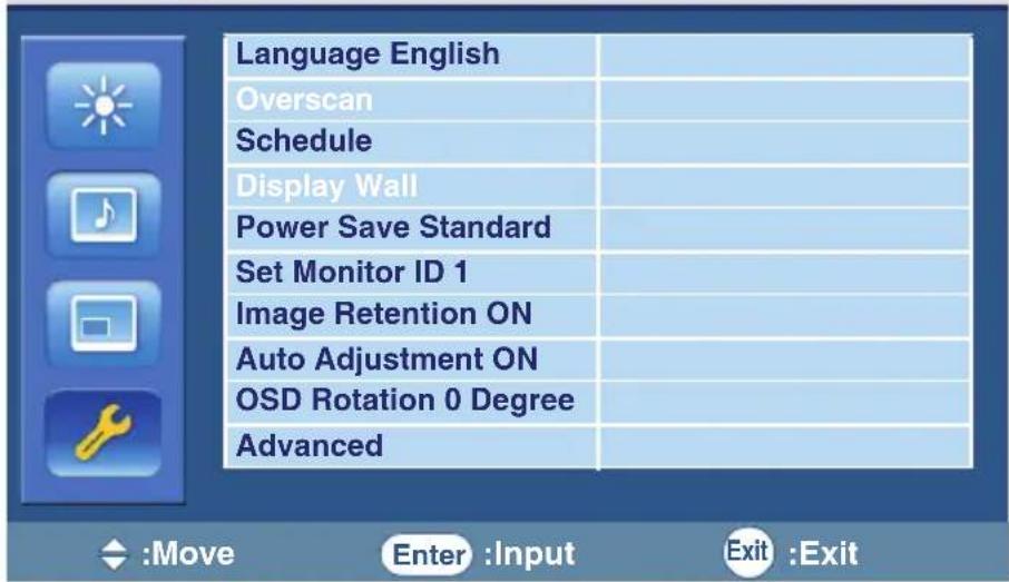
text_image
Language English Overscan Schedule Display Wall Power Save Standard Set Monitor ID 1 Image Retention ON Auto Adjustment ON OSD Rotation 0 Degree AdvancedName Description
| Language Sets your preferred language for the OSD menu. | |
| Overscan Turns the HDMI overscan function on or off. | |
| Schedule | Date and Time: Sets the current date and time.Schedule: Sets when to turn on or off the display and which input source should be used for each schedule.Notes:Set the current time before you set the Schedule.When schedule settings overlap, the Every Day setting takes priority over other weekly settings.When schedule settings overlap, scheduled power-on time takes priority over scheduled power-off time.If two schedules have the same settings, the first schedule on the list will take priority. |
| Display Wall | H Monitors: Sets the number of displays used in the horizontal position.V Monitors: Sets the number of displays used in the vertical position.H Position: Sets the horizontal position of the display wall matrix.V Position: Sets the vertical position of the display wall matrix.Frame Comp.: Adjusts images near the display edges for optimal demonstration across the display wall. |
| Power Save | Sets the display to enter the power saving mode when there is no signal detected.Eco: All source can enter the power saving mode, but only a VGA signal can wake up the display or you have to press the power button to wake up the display when other source is connected.Standard: All source can enter the power saving mode and wake up the display.Off: If no source is detected, the backlight will continue on.VGA Only: Only the VGA signal can enter the power saving mode and wake up the display.Note: Serial can bring any mode out of the power savings. |
| Set Monitor ID | Assigns an ID number for the current display when multiple displays are connected. |
| Image Retention | Automatically displays swift moving patterns every 10 seconds to prevent image retention on the screen. |
| Auto Adjustment | Automatically optimizes image display for the VGA input. |
| OSD Rotation | Adjusts the OSD rotation.Note: See product specifications for models recommended for portrait orientation. Landscape only models operated in portrait mode may result in premature failure and will not be covered under the warranty. |
| Advanced | Reset User Default: Resets all OSD settings (except the Language setting) to the factory settings.OSD Info Box: When turned ON, the display will always show the current input source and resolution onscreen. Select OFF to show the information box onscreen only when you press INFO. on the remote control.StatusThermal: Shows current temperature inside the display.Ambient Light: Shows current ambient brightness around the display.5V Detect: Shows the current 5V voltage detection result.12V Detect: Shows the current 12V voltage detection result.Operating Time: Shows the time elapsed since the display was last turned on. D=Day, H=Hour.FW Version: Shows the current firmware version.Input Source: Shows the current input source and its resolution. |
Product Information
Specifications
| Item Specifications | |||
| Model PS4200 PS4250 | |||
| LCD panel | Active area (H x V) (mm) 930.24 x 523.26 930.24 x 523.26 | ||
| Pixel pitch (mm) 0.4845 0.4845 | |||
| Native resolution (pixels) 1920 x 1080 1920 x 1080 | |||
| Brightness (cd/m2) 500 | (typical) 500 | (typical) | |
| Contrast 1500:1 (typical) 4000:1 (typical) | |||
| Response time (ms) | 5 (typical) | 5.5 (typical) | |
| Input | Computer | VGA (Mini D-Sub 15-pin), DVI (DVI-D) | |
| Video | Composite Video (BNC jacks), S-Video, Y Pb Pr (RCA jacks), HDMI | ||
| Audio | L/R (RCA jacks), Line-in (3.5 mm Mini-jack) | ||
| Control | RS-232C (Mini D-Sub 9-pin) | ||
| Output | Computer | VGA (Mini D-Sub 15-pin) | |
| Video | Composite Video (BNC jacks) | ||
| Speaker | External speaker jack (12W+12W, 8 Ohms) | ||
| Audio | L/R (RCA jacks) | ||
| Control | RS-232C (Mini D-Sub 9-pin) | ||
| Audio | Audio W (Amp) | 12W | 12W |
| Internal speaker | Yes | No | |
| Power | Supply | 100 - 240V AC, 50/60 Hz | |
| Consumption Max. | < 210W | <150W | |
| Consumption Standby | < 1W | < 0.5W | |
| Environment | Display Orientation | Landscape | Landscape/Portrait |
| Operating Temperature | 0 - 40°C, 32 - 104°F | ||
| Operating Humidity | 10 - 90% RH Non-Condensing | ||
| Storage Temperature | -20 - 60°C, 4 - 140°F | ||
| Storage Humidity | 10 - 95% RH Non-Condensing | ||
| Mechanical | Weight (lbs/kg) | 54.0/24.5 (Approximately) | 48.5/22 (Approximately) |
| Dimensions | 39.1 x 23.0 x 4.7/ | 38.3 x 22.4 x 2.6/ | |
| (W x H x D) (inch/mm) | 992 x 585 x 119.6 | 971.8 x 568.6 x 67 | |
Note:
Specifications and functions are subject to change without notice.
| Item Specifications | |||
| Model PS4650 PS5550 | |||
| LCD panel | Active area (H x V) (mm) 1018.08 x 572.67 1209.6 x 680.4 | ||
| Pixel pitch (mm) 0.53025 0.21 x 0.63 | |||
| Native resolution (pixels) 1920 x 1080 1920 x 1080 | |||
| Brightness (cd/m2) 500 | (typical) 400 | (typical) | |
| Contrast 4000:1 (typical) | 4000:1 (typical) | ||
| Response time (ms) | 6.5 (typical) 6.5 (typical) | ||
| Input | Computer | VGA (Mini D-Sub 15-pin), DVI (DVI-D) | |
| Video | Composite Video (BNC jacks), S-Video, Y Pb Pr (RCA jacks), HDMI | ||
| Audio | L/R (RCA jacks), Line-in (3.5 mm Mini-jack) | ||
| Control | RS-232C (Mini D-Sub 9-pin) | ||
| Output | Computer | VGA (Mini D-Sub 15-pin) | |
| Video | Composite Video (BNC jacks) | ||
| Speaker | External speaker jack (12W+12W, 8 Ohms) | ||
| Audio | L/R (RCA jacks) | ||
| Control | RS-232C (Mini D-Sub 9-pin) | ||
| Audio | Audio W (Amp) | 12W | 12W |
| Internal speaker | No | No | |
| Power | Supply | 100 - 240V AC, 50/60 Hz | |
| Consumption Max. | < 160W < 185W | ||
| Consumption Standby | < 0.5W < 0.5W | ||
| Environment | Display Orientation | Landscape/Portrait | Landscape |
| Operating Temperature | 0 - 40°C, 32 - 104°F | ||
| Operating Humidity | 10 - 90% RH Non-Condensing | ||
| Storage Temperature | -20 - 60°C, 4 - 140°F | ||
| Storage Humidity | 10 - 95% RH Non-Condensing | ||
| Mechanical | Weight (lbs/kg) | 57.3/26 (Approximately) | 60.0/27.2 (Approximately) |
| Dimensions(W x H x D) (inch/mm) | 41.7 x 24.4 x 2.6/1060.3 x 618.7 x 67 | 49.6 x 28.8 x 2.31259.8 x 731.9 x 59 | |
Note:
Specifications and functions are subject to change without notice.
| Item Specifications | ||
| Model PS4670 | ||
| LCD panel | Active area (H x V) (mm) 1018.08 x 572.67 | |
| Pixel pitch (mm) 0.53025 | ||
| Native resolution (pixels) 1920 x 1080 | ||
| Brightness (cd/m2) 1500 | (typical) | |
| Contrast 4000:1 (typical) | ||
| Response time (ms) 8 (typical) | ||
| Input | Computer VGA (Mini D-Sub 15-pin), DVI (DVI-D) | |
| Video | Composite Video (BNC jacks), S-Video, Y Pb Pr (RCA jacks), HDMI | |
| Audio L/R (RCA jacks), Line-in (3.5 mm Mini-jack) | ||
| Control RS-232C (Mini D-Sub 9-pin) | ||
| Output | Computer VGA (Mini D-Sub 15-pin) | |
| Video Composite Video (BNC jacks) | ||
| Speaker | External speaker jack (12W+12W, 8 Ohms) | |
| Audio | L/R (RCA jacks) | |
| Control RS-232C (Mini D-Sub 9-pin) | ||
| Audio | Audio W (Amp) | 12W |
| Internal speaker | No | |
| Power | Supply | 100 - 240V AC, 50/60 Hz |
| Consumption Max. | < 300W | |
| Consumption Standby | < 0.5W | |
| Environment | Display Orientation | Landscape/Portrait |
| Operating Temperature | 0 - 40°C, 32 - 104°F | |
| Operating Humidity | 10 - 90% RH Non-Condensing | |
| Storage Temperature | -20 - 60°C, 4 - 140°F | |
| Storage Humidity | 10 - 95% RH Non-Condensing | |
| Mechanical | Weight (lbs/kg) | 59.5/27 (Approximately) |
| Dimensions(W x H x D) (inch/mm) | 41.7 x 24.2 x 4.9/1058 x 614.5 x 124.2 | |
Note:
Specifications and functions are subject to change without notice.
| Item Specifications | ||
| Model PS6500 | ||
| LCD panel | Active area (H x V) (mm) 1428.48 x 803.52 | |
| Pixel pitch (mm) 0.744 | ||
| Native resolution (pixels) 1920 x 1080 | ||
| Brightness (cd/m2) | 5 (typical) 0 | |
| Contrast 5000:1 (typical) | ||
| Response time (ms) 8 (typical) | ||
| Input | Computer VGA (Mini D-Sub 15-pin), DVI (DVI-D) | |
| Video | Composite Video (BNC jacks), S-Video, Y Pb Pr (RCA jacks), HDMI | |
| Audio L/R (RCA jacks), Line-in (3.5 mm Mini-jack) | ||
| Control RS-232C (Mini D-Sub 9-pin) | ||
| Output | Computer VGA (Mini D-Sub 15-pin) | |
| Video | Composite Video (BNC jacks) | |
| Speaker | External speaker jack (12W+12W, 8 Ohms) | |
| Audio | L/R (RCA jacks) | |
| Control RS-232C (Mini D-Sub 9-pin) | ||
| Audio | Audio W (Amp) | 12W |
| Internal speaker | No | |
| Power | Supply 100 - 240V AC, 50/60 Hz | |
| Consumption Max. | < 550W | |
| Consumption Standby | < 1W | |
| Environment | Display Orientation Landscape | |
| Operating Temperature | 0 - 40°C, 32 - 104°F | |
| Operating Humidity | 10 - 90% RH Non-Condensing | |
| Storage Temperature | -20 - 60°C, 4 - 140°F | |
| Storage Humidity | 10 - 95% RH Non-Condensing | |
| Mechanical | Weight (lbs/kg) | 119.1/54 (Approximately) |
| Dimensions(W x H x D) (inch/mm) | 60.0 x 35.1 x 4.9/1523.6 x 891.6 x 124.8 | |
Note:
Specifications and functions are subject to change without notice.
Supported Input Signal Resolution
- Blank: not supported
Supported PIP Input Signal Combination
| Main picture signal source | |||||||
| AV S-Video | VGA YPbPr | DVI HDMI | |||||
| Sub picture signal source | AV | × | × | × | × | × | × |
| S-Video | × | × | × | × | × | × | |
| VGA | × | × | × | × | ○ | ○ | |
| YPbPr | × | × | × | × | ○ | ○ | |
| DVI | × | × | ○ | ○ | × | × | |
| HDMI | × | × | ○ | ○ | × | × | |
Supported Signal Source and Resolution in PIP Mode
Notes:
• O: supported
- Blank: not supported
| Problem Solution | |
| No picture | Check the following:Is the display turned on? Check the power indicator of the display.Is the signal source device turned on? Turn on the device and try again.Are there any loose cable connections? Make sure that all cables are connected firmly.Have you chosen an unsupported output resolution on the computer? Refer to "Supported Input Signal Resolution" on page 29 to select a supported resolution and try again.Have you chosen an unsupported output resolution on the DVD or Blu-ray disc player? Refer to "Supported Input Signal Resolution" on page 29 to select a supported resolution and try again. |
| No sound | Check the following:Have you turned on the mute function on the display or the input source device? Turn off the mute function or increase the audio volume level and try again.Are there any loose cable connections? Make sure that all cables are connected firmly. |
| The computer input image looks strange | Have you chosen an unsupported output resolution on the computer? Refer to "Supported Input Signal Resolution" on page 29 to select a supported resolution and try again.Use the Auto Adjustment function (See "Auto Adjustment" on page 22) to let the display automatically optimize the display of computer image.If the result of the Auto Adjustment function is not satisfactory, use the Clock Frequency, Phase, H Position and V Position functions to manually adjust the image. |
| The control panel buttons do not work | Have you locked the control panel buttons? Unlock the buttons and try again. |
| The remote control does not work | Have you locked the remote control function? Unlock the function and try again.Check for incorrect battery orientation.Check for dead batteries.Check your distance and angle from the display.Check whether remote control is properly being pointed at the display's remote control sensor window.Check for any obstacle between the remote control and the remote control sensor window.Check that the remote control sensor window is not under strong fluorescent lighting. or in direct sunlight.Check for any devices (computer or personal digital assistant, PDA) nearby that transmit infrared signals which may cause interference to signal transmission between the remote control and the display. Turn off the infrared function of these devices. |
Planar Systems, Inc.
Customer Service
24x7 Online Technical Support: http://www.planar.com/support
Americas Support
Tel: 1-866-PLANAR1 (866-752-6271) or +1 503-748-1100
Hours: M-F, 9am - 7pm Eastern Time | M-F, 6am - 4pm Pacific Time
Europe and Asia-Pacific Support
Tel: +358-9-420-01
Hours: M-F, 7:00am - 4pm CET
© 2011 Planar Systems, Inc. 05/08 Planar is a registered trademark of Planar Systems, Inc.
Other brands and names are the property of their respective owners.
Technical information in this document is subject to change without notice.
Document No. 020-1128-00 Rev. B.