SD2220W - Monitor Planar - Free user manual and instructions
Find the device manual for free SD2220W Planar in PDF.

User questions about SD2220W Planar
0 question about this device. Answer the ones you know or ask your own.
Ask a new question about this device
Download the instructions for your Monitor in PDF format for free! Find your manual SD2220W - Planar and take your electronic device back in hand. On this page are published all the documents necessary for the use of your device. SD2220W by Planar.
USER MANUAL SD2220W Planar
Stereoscopic Monitor
USER'S GUIDE
www.planar3d.com
FCC Statement Warning
This equipment has been tested and found to comply with the limits for a Class B digital device, pursuant to Part 15 of the FCC Rules. These limits are designed to provide reasonable protection against harmful interference in a residential installation. This equipment generates, uses, and can radiate radio frequency energy, and if not installed and used in accordance with the instruction, may cause harmful interference to radio communications. However, there is no guarantee that interference will not occur in a particular installation. If this equipment does cause harmful interference to radio or television reception, which can be determined by turning the equipment off and on, the user is encouraged to try to correct the interference by one or more of the following measures:
- Reposition or relocate the receiving antenna.
- Increase the separation between the equipment and the receiver.
- Connect the equipment into an outlet on a circuit different from that to which the receiver is connected.
- Consult the dealer or an experienced monitor technician for help.
Warning
Use only shielded signal cables to connect I/O devices to this equipment. You are cautioned that changes or modifications not expressly approved by the party responsible for compliance could void your authority to operate the equipment.
This device complies with part 15 FCC Rules. Operation is subject to the following two conditions (1) This device may not cause harmful interference. (2) This device must accept any interference received, including interference that may cause undesired operation.
Canadian DOC Notice

Planar Systems, Inc.
1195 NW Compton Drive
Beaverton, OR 97006-1992
www.planar.com
© 2009 Planar Systems, Inc. Planar is a registered trademark of Planar Systems, Inc. Other brands and names are the property of their respective owners. Technical information in this document is subject to change without notice. 06/09
020-0989-00A
Usage Notice

To prevent the risk of fire or shock hazards, do not expose this product to rain or moisture.
Do not open or disassemble the product, as doing so may cause electric shock.
Follow all warnings, precautions, and maintenance as recommended in this user's guide to maximize the life and performance of your unit.
Do
- Turn off the monitors before cleaning.
- Use only a dry, soft cloth or clean room wipe when cleaning the LCD panel surface or the half-mirror.
- Use a soft cloth moistened with water and/or mild detergent to clean the display housing and stand.
- Use only high quality and safety approved AC/DC power adapters.
- Disconnect the power plug from the grounded AC outlet if the product will not be used for a long period of time.
Don't
- Do not touch the LCD panel or half-mirror surfaces with sharp or hard objects.
- Do not use abrasive cleaners, waxes, or solvents for your cleaning.
- Do not operate the product under these conditions:
— In an extremely hot, cold, or humid environment
— In areas susceptible to excessive dust and dirt
— Near any appliance generating a strong magnetic field
— In direct sunlight
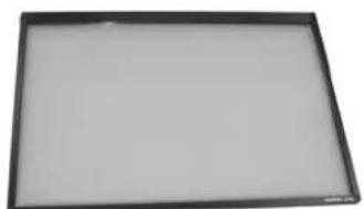
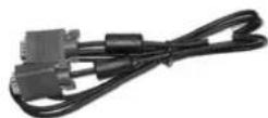
Box Contents
The SD2220W shipping box contains the following components:
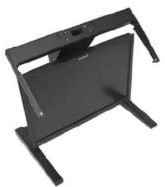
natural_image
Black electronic device with adjustable legs and a flat top (no visible text or symbols)Bottom monitor assembly with mirror support arms and mirror adjustment screws
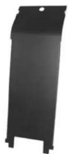
natural_image
Black rectangular object with a hole at the top, resembling a trash bin or container (no text or symbols visible)Bottom cable management cover
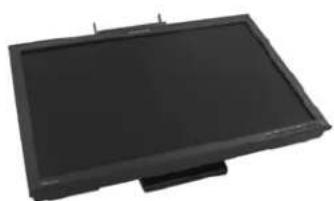
natural_image
Black rectangular electronic device with a flat top and small base (no visible text or symbols)Top monitor assembly
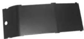
Top cable management cover
natural_image
Blank rectangular frame with black border (no text or symbols)Beamsplitter assembly
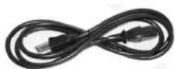
Two power cords (6-ft and 10-ft)
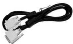
Two DVI cables (6-ft and 12-ft)
Two Analog VGA cables (6-ft and 10-ft)
Mirror-flip PCI card
Short DVI cables (14-in)
Product user's guide

Captain-style glasses (2 ea)
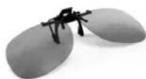
Spring clip-style glasses (1 ea)

Terminator-style glasses (2 ea)

Soft, dry cloths (3 ea)

Moistened cleaning pads (6 ea)
Contents
Usage Notice ....iii
Do ....iii
Don't....iii
Box Contents....iv
Stereoscopic Viewing ....1
StereoMirror™ Technology 2
Getting Started 4
Assemble the unit....4
Select a graphics card ....6
Install the mirror-flip PCI card ....6
Connect the cables....7
Connect the power cords....8
Check the alignment 8
Product Use....9
Operating in 2D mode....9
User controls....10
OSD menu 11
Power management.... 13
Monitor Specifications....13
LCD Panel....13
Plug and Play....14
Enviroment....14
Size and Weight....14
System Care 16
Software Compatibility....16
Accessories....16
Troubleshooting....17
Warning Signals....18
Warranty....18
Product Registration....18
CRT Recycling....19
Important Recycle Instructions....19
Stereoscopic Viewing
We live in a three-dimensional world. The human visual system can process the slightly different views of the world and translate the views into the perception of depth. This process is called stereopsis.
In the last two centuries much effort has been devoted to the reproduction of depth perception, primarily with photography and more recently with computer graphic images.
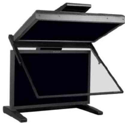
Stereoscopic/3D viewing can help a viewer make faster, more accurate, and more enjoyable interpretations of imagery. The SD2220W StereoMirror™ monitor, in particular, creates an unprecedented level of stereo/3D viewing quality and viewer comfort.
natural_image
Exterior view of a modern office building (no signage)The StereoMirror monitor
Stereo viewing is useful for the following applications:
• Photogrammetry and remote sensing
- Geospatial image analysis
- Geophysical modeling
• Molecular modeling
- Computer games
• Oil and gas exploration
• Architecture and mechanical design
• Stereo photography or videography
• Medical imaging (not as yet FDA 510(k) approved)
- Surgical planning
- Teaching of anatomy
- Simulation
• Complex data analysis
• Autonomous vehicle piloting

For some individuals, prolonged use of any stereoscopic monitor may cause discomfort. Take a break from stereo viewing if you sense eye fatigue. Individuals who are unaccustomed to using stereoscopic 3D monitors may require a period of adaptation.
StereoMirror™ Technology
A StereoMirror™ monitor consists of two AMLCD (Active Matrix Liquid Crystal Display) units, oriented at a 110° angle and mounted on a specially designed stand. A passive beamsplitter mirror bisects the angle formed between the two monitors, and there is a fine mechanical adjustment for the mirror angle between the two displays. One side of the glass mirror has a reflective coating, and the other side has an anti-reflective coating to minimize secondary reflections. The mirror has been treated with a hard top coating to accommodate cleaning.
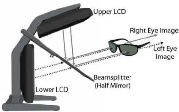
In general, the objective of a stereoscopic display is to efficiently present a left eye image solely to the left eye while the right eye image is directed to the right eye. This allows the human visual system to merge the two images and results in the
perception of depth, or stereopsis. In the StereoMirror™ design this stereo separation is achieved using the principle of conservation of polarization.
Liquid crystal displays operate based on the ability of liquid crystal material to modulate plane-polarized light. The two AMLCDs in the SD2220W model have been manufactured so that the polarized light emitted from the top monitor is 90^ rotated from that of the bottom monitor. The image from the lower monitor is seen through the mirror, as shown in the illustration above. When stereo pair images from the two monitors are viewed through crossed-polarizing glasses (glasses with polarizing films mounted on the eyepieces with their planes of polarization at a right angle to one another), the user only sees the left eye image with the eyepiece having the 135°-oriented polarizer and the right eye image with the eyepiece having the 45° polarizer. Light with a perpendicular polarization is not transmitted. The result is a single, fused stereoscopic image.
text_image
Upper LCD Right Eye Image Left Eye Image Lower LCD Beamsplitter (Half Mirror)Operating principle of the StereoMirror monitor
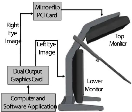
One of the benefits of StereoMirror's use of light polarization properties is the ability to utilize a 3rd, non-stereo monitor in conjunction with the stereo system. Any flat panel monitor with a 0°, 90°, or 180° polarization angle can be used while wearing the SD glasses.
A block diagram describing the process of driving a StereoMirror ^™ monitor with a computer is shown in the illustration below. The left eye and right eye images are sent to their respective AMLCDs independently and without any special treatment (with the exception of accommodating for the fact that the upper monitor is seen in a mirror; see discussion below). Presenting the stereo pair of images requires a setup or software application that accommodates dual-monitor stereo viewing. No additional modification is needed for use with the StereoMirror ^™ monitor design.
Any software application that uses the OpenGL quad-buffered stereo features is compatible with the StereoMirror. ^™ Quad-buffered stereo is a feature of the OpenGL 3D graphics library that allows an application to define two separate right/left eye viewpoints instead of the normal single monoscopic viewpoint. The two viewpoints are defined to give the correct parallax separation for the proper stereo effect. Once the two view-points have been defined the 3D scene is rendered identically for each of the two view-points. Many commercial 3D applications already have stereo viewing modes using the OpenGL stereo features.
Since the upper display of the monitor is seen in reflection, a mirror-flip operation must be performed on that data path. In the current product this is accomplished using an auxiliary signal processing board in the data path to the
flowchart
graph TD
    A["Computer and Software Application"] --> B["Dual Output Graphics Card"]
    B --> C["Right Eye Image"]
    B --> D["Left Eye Image"]
    C --> E["Mirror-flip PCI Card"]
    D --> E
    E --> F["Top Monitor"]
    E --> G["Lower Monitor"]
Driving the StereoMirror monitor
upper monitor. Driving a StereoMirror™ monitor is identical with driving a pair of projection displays used to show stereoscopic images with crossed polarizers in the two separate light paths. An off-the-shelf, dual-output graphics card is employed to drive the two monitors, again with no special preparation.
For more information on StereoMirror™ technology, go to www.planar.com/advantages/whitepapers.
Getting Started
Read all instructions before assembling the monitor. Improper assembly can result in damage to the display components.
Assemble the unit
- Remove the bottom monitor assembly from the shipping box and place it on a sturdy table or desktop. To keep the display surface clean, avoid touching the screen.
- Remove the top monitor assembly from the shipping box. Loosen the two screws on the cover of the cable management compartment and remove the cover.
- Slide the aluminum flanges of the upper assembly into the holes on the cross bracket of the bottom monitor assembly until fully seated. Continue to support the top monitor assembly and tighten the four thumb screws.
natural_image
3D rendering of a flat-screen monitor with adjustable stand (no text or symbols visible)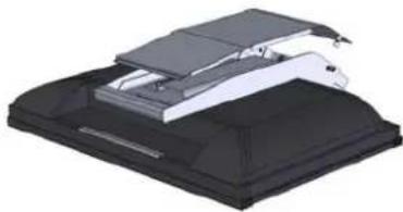
natural_image
3D rendering of a mechanical device with layered components (no visible text or symbols)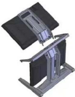
natural_image
3D mechanical assembly diagram showing two stacked components with no visible text or symbols- Thread the cables from the top monitor through the rectangular hole in the cross bracket.
natural_image
3D rendering of a mechanical device with a central bracket and mounting base (no text or symbols visible)- Replace the top and bottom cable covers, if desired.
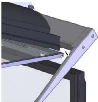
natural_image
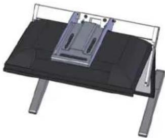
3D mechanical assembly diagram showing layered components with no visible text or symbols- Remove the beamsplitter from the shipping case. With the StereoMirror™ logo oriented to the lower right, insert the pins located on either side of the mirror frame into the corresponding slots on the mirror support arms. The pins should rest in the fully forward position of the mounting arm slots.
natural_image
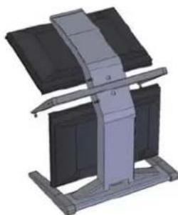
3D mechanical assembly diagram showing a bracket with mounting holes and a highlighted section (no text or symbols)Select a graphics card
The SD2220W unit requires a dual-output graphics card to drive the two monitors with a DVI signal. For professional applications that use OpenGL quad-buffered stereo, the graphics card should support OpenGL stereo as well. Typically, the two monitors should be in clone mode for these applications.
There are several compatible graphics card families. The NVIDIA Quadro FX line and the Matrox Parhelia line have all been tested and are compatible for OpenGL stereo applications. The NVIDIA GeForce line offers dual-DVI output graphics cards that work well for PC gaming and DirectX applications. AMD FireGL cards are also compatible with the SD line.
Visit www.planar3d.com for more details on graphics cards, software configuration, and using side monitors with the SD2220W unit.
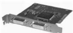
Install the mirror-flip PCI card

Proper ESD (electrostatic discharge) handling precautions should be exercised when installing the mirror-flip PCI card. Consult the computer manual for proper installation of graphics cards.
Because the viewer will see a reflection of the top monitor, this image needs to be flipped on the horizontal axis. A mirror-flip PCI card is included with the SD2220W unit. Plug this card into a free PCI slot in your computer. There are no drivers to load with the card.
- Remove the blank bracket from an available PCI slot.
- Insert the mirror-flip PCI card into the slot, align the connector pins, and press the board down until it is firmly seated.
- Secure the mounting bracket.
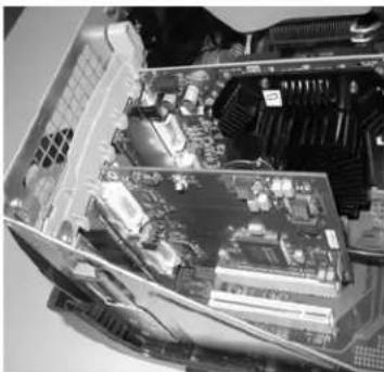
natural_image
Interior view of a computer motherboard showing CPU socket, RAM slots, and motherboard (no visible text or labels)Mirror-flip PCI card installed
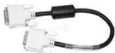
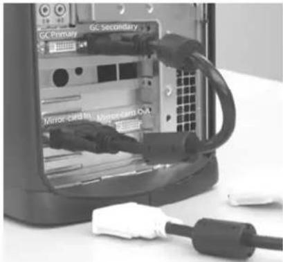
Connect the cables
The SD2220W unit comes with one 6-foot DVI cable, one 12-foot DVI cable, and one 14-inch DVI cable.
-
Plug one end of the 6-foot DVI cable into the primary port of the dual-channel DVI graphics card. Plug the other end into the bottom monitor of the SD2220W unit.
-
Plug one end of the 14-inch DVI cable into the secondary output of the dual-channel graphics card. Plug the other end into the input port (labeled "IN") of the mirror-flip PCI card.
-
Plug one end of the 12-foot DVI cable into the output port of the mirror-flip PCI card (labeled "OUT"). Plug the other end into the top monitor of the SD2220W unit.
text_image
GC Primary GC Secondary Mirror card Pt. Mirror card O/AShort DVI cable installed

The two monitors must be connected with an off-the-shelf video cable to comply with FCC regulations. Ferrite-core interface cables are provided. This device will not be in compliance with FCC regulations when a non-ferrite-core video cable is used.
Connect the power cords
Two power cords shipped with the unit. Use only the power cords supplied with the unit.
- Plug the 10-foot cord into the AC power jack of the top monitor. Plug the 6-foot cord into the bottom monitor. Then plug the power connectors into a grounded outlet.
- Turn on the soft power switch located on the front bezel of the two LCD monitors.
- Power up the computer.
Check the alignment
Although the SD2220W unit is aligned during manufacturing, it may require realignment after reassembly at your site. There are two fine adjustment screws located on the mirror support arms. Rotating these screws raises or lowers the beamsplitter mirror. Adjust the screws so that the corners of the reflected image of the upper monitor are aligned with the corners of the transmitted image from the lower monitor.
You may want to use a test image during the alignment process. A sample is available at www.planar3d.com.
Perfect alignment between the two images is not required for stereo viewing. The human visual system is typically adept at "fusing" two images that are slightly shifted relative to each other. This is especially true for horizontal alignment. In a careful manner, try to achieve vertical alignment as closely as possible. Coarse vertical misalignment can cause eye fatigue or headaches since the eyes are accustomed to seeing stereo images from the same vertical position.
Product Use
Operating in 2D mode
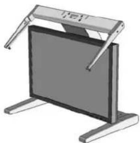
Your SD2220W unit can operate either as a 3D stereoscopic monitor or in the standard 2D mode. Converting to 2D viewing can be accomplished by either turning off the power to one of the monitors or by putting the mirror into the locked upright position. To move the mirror to the raised position, use two hands to slide it up the mirror support arms and then raise it until it drops into the locked position. To lower the mirror, use two hands to lift it out of the locked slot and then lower it down onto the fine adjustment screws.
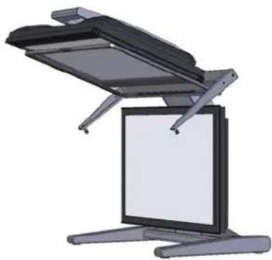
natural_image
Illustration of a flat-screen office chair with open lid and stand (no text or symbols)StereoMirror in 2D mode

The mirror should not be forced down. This can break the glass and damage the mirror frame. The mirror must be pulled forward before lowering.
User Controls
text_image
AUTO / EXIT 6 5 4 3 2 1 MENU / ENTER| 1 | Power LED will be Green when monitor is on, be yellow when in power saving mode, be dark when monitor in off mode. | |
| 2 |  | Power ON/OFF switch. Push to power on or power off. (Toggle switch) |
| 3 | Menu/Enter | Shows main OSD menu/ Enter key (in OSD menu)/ Audio mute and unmute ( must activate Volume OSD first, push ▲ / ▶ then Menu/Enter) |
| 4 |  | Shows Volume OSD/ Moves right or up (in OSD menu) |
| 5 |  | Selects input source/ Moves left or down (in OSD menu) |
| 6 | Auto/Exit | Auto adjustment (in D-Sub input only)/ Exit OSD menu/ Exit (in OSD menu) |
OSD Menu
| Main Menu icon | Sub Menu item | Sub Menu item | Description |
 | Preset Mode | STANDARD | Default Setting. Reflects native display capability. |
| MOVIE | Displays scenes in clearest detail. Pictures and photographs appear in vibrant colors with sharp detail. | ||
| GAME Enhances color. | |||
| TEXT | Optimal balance of brightness and contrast prevent eyestrain. The most comfortable way to read onscreen text | ||
| PHOTO Enhances colors and emphasize fine detail. | |||
| Brightness | Adjusts the background brightness of the screen image. | ||
| Contrast | Adjusts the contrast between the foreground and background of the screen image. | ||
| Auto Contrast | Adjusts the contrast of screen image automatically. | ||
| Black Level | Adjusts the black level of screen image. | ||
| Sharpness | Adjusts the scaling effect. (smoother or sharper.) | ||
 | Expansion Mode | FULL Selects wide format for display. | |
| ASPECT Selects 4:3 format for display. | |||
| Auto Adjustment | Auto adjusts the H/V Position, Phase and Clock of picture. (available in analog mode only) | ||
| H. Position | Adjusts the horizontal position.(available in analog mode only) | ||
| V. Position | Adjusts the vertical position.(available in analog mode only) | ||
| Clock | Adjusts picture Clock.(available in analog mode only) | ||
| Phase | Adjusts picture Focus.(available in analog mode only) | ||
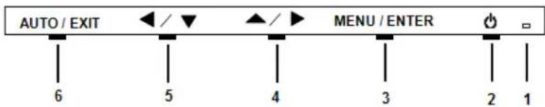
 | 9300K Sets the color temperature to 9300K. | ||
| 7500K Sets the color temperature to 7500K. | |||
| 5000K Sets the color temperature to 5000K. | |||
| sRGB Sets the color temperature to sRGB. | |||
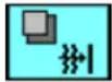
| User R/G/B Allows users to adjust red/green/blue intensity. | |||
 | Language | ||
| OSD H. Position | Adjusts the horizontal position of the OSD. | ||
| OSD V. Position | Adjusts the vertical position of the OSD. | ||
| OSD Turn Off | Adjusts the OSD timeout. | ||
 | Volume Adjusts the volume of audio | ||
| Input Select | D-SUB Selects input signal to analog (D-Sub) | ||
| DVI Selects input signal to digital (DVI) | |||
| Resolution Select | 720/640x4001360/1280/1024x7681680/1400x1050 | ||
| DDC/CI ON/OFF Turns ON/OFF DDC/CI support | |||
| Recall | |||
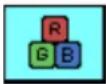
 | Information | ||
| Icon Function Description | ||
| 9300 | CIE coordinated Color Temperature of 9300°K | Sets the CIE coordinate color temperature to 9300°K |
| 7500 | CIE coordinated Color Temperature of 7500°K | Sets the CIE coordinate color temperature to 7500°K |
| 5000 | CIE coordinated Color Temperature of 6500°K | Sets the CIE coordinate color temperature to 5000°K |
| User | Three colors (Red, Green, Blue) can be adjusted from the OSD menu | Sets the settings to a by user defined CIE Temperature. |
NOTE: Changing the Brightness setting can reduce the number of discernable gray levels.
Power Management
This LCD monitor complies with the VESA DPMS (version 1.0) Power Management guidelines. The VESA DPMS provides four power-saving modes through detection of a horizontal or vertical sync signal. When the LCD monitor is in power-saving mode, the monitor screen is blank and the power LED indicator light is amber.
Monitor Specifications
| LCD Panel | |
| Size | 22W" |
| Display Type Active matrix color | TFT LCD |
| Resolution 1680 x 1050 | |
| Display Dot 1680 x (RGB) x 1050 | |
| Display Color 16.2M with FRC or | Dithering |
| Video | ||
| Input Signal Analog RGB 0.7Vp-p | Digital TMDS | |
| Input Impedance 75 Ohm ± 2% | ||
| Polarity | Positive, Negative | |
| Amplitude 0 - 0.7 ± 0.05 Vp | ||
| Multi-mode Supported | Horizontal Frequency: 30 ~ 83 kHzVertical Frequency: 56 ~ 75 Hz | 30~80kHz56~75Hz |
| Control | |
| Power switch (hard and soft types) | On/Off switch with LED indicator |
| Audio | |
| Input | 500mVrms |
| Output | 1W +1W |
| OSD | |
| Brightness | Digital |
| Contrast | Digital |
| Horizontal Position Digital | |
| Vertical Position Digital | |
| Phase | Digital |
| Clock | Digital |
| Display Mode Setup Use EEPROM to save settings in memor. | |
Power Management
| Mode | Power Consumption* | AC Input | LED Color |
| DPM On 52 W maximum 240 VAC Green | |||
| DPM Off 2 W maximum 240 VAC Yellow | |||
| DC switch off Off 1 W maximum 240 VAC Dark | |||
| Disconnected 2 W maximum 240 VAC |
*Meeting VESA DPM requirements measured from AC Input end of AC power cord.
| Sync Input | Analog | Digital |
| Signal | Separate TTL compatible horizontal and vertical synchronization. | TMDS |
| Polarity | Positive and negative | -- |
Plug and Play
The unit supports the VESA DDC2B functions of Plug and Play.
Environment
| Operating conditions, Temperature | 10°C - 35°C (50°F – 95°F) |
| Operating conditions, Relative humidity | 5 to 95% (noncondensing) |
| Storage Conditions, Temperature | -20°C to 60°C (-4°F to 140°F) |
| Storage Conditions, Relative humidity | 5 to 95% (noncondensing) |
Size and weight
| System width 23.1" (588 mm) | |
| System depth 20.7" (525 mm) | |
| System height 24.8" (631 mm) | |
| System weight 60 lb (27 kg) |
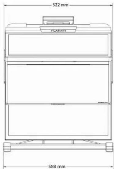
text_image
522 mm PLANAR 588 mm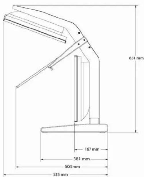
text_image
631 mm 167 mm 381 mm 504 mm 525 mmDimensions of monitor unit, front and side
System Care
Monitors - Turn off the monitors before cleaning. Use a dry, soft cloth, clean room wiper, or compressed air when cleaning the LCD panel surface. A soft cloth moistened with water and/or mild detergent can be used to clean the display housing and stand. Do not touch the LCD panel surfaces with sharp or hard objects. Do not use abrasive cleaners, waxes, or solvents for cleaning.
Mirror - Use a dry, soft cloth, clean room wiper, or compressed air when cleaning the mirror surface. A soft cloth moistened with glass cleaner, water, and/or mild detergent can also be used to clean the mirror. Do not touch the half-mirror surfaces with sharp or hard objects. Do not use abrasive cleaners, waxes, or solvents for cleaning.
Polarized glasses - Use a dry soft cloth, clean room wiper, or compressed air when cleaning the polarized glasses. A soft cloth moistened with water and/or mild detergent can also be used to clean the glasses. Do not touch the surfaces of the polarized glasses with sharp or hard objects. Do not use abrasive cleaners, waxes, or solvents for cleaning.
Software Compatibility
OpenGL - The SD2220W unit is compatible with OpenGL stereo. An appropriate graphics card is required to drive the two monitors with DVI signals. For professional applications that use OpenGL stereo support, the graphics card should support OpenGL stereo as well. Stereo viewing of professional applications is typically done in the so-called clone mode where most of the same information is duplicated on the left and right monitor, except for the stereo imagery. In other words, the desktop, windows, and menus are identical, but the bottom monitor shows the left-eye image while the top monitor exhibits the right-eye image.
DirectX - The SD2220W unit is compatible with the DirectX application programming interface.
Accessories
For repetitive transportation of the SD2220W unit, a reusable, ruggedized shipping case is available from Planar Systems. The case features a tough plastic shell, locks, customized foam inlay, and wheels.
Additional polarized glasses are available from Planar in three styles: Captain, Terminator, and Spring-Clip (for attaching to prescription glasses).
Contact Planar via the web site (www.planar3d.com) or toll free at 1-866-475-2627. Accessories can also be purchased through Planar resellers.
Troubleshooting
| Problem | Possible Solution |
| No image appears on the screen. | Check that all the power cord connections are secure.Check that the power buttons on the side and front of both monitors are switched on and that the power indicator light is green.Check that the DVI cables are securely fastened to the graphics card, the mirror-flip PCI card, and the two monitors.Make sure that the pins of the DVI connectors are not bent or broken.If only the bottom monitor appears to be working, make sure the graphics card is not in the single-monitor mode. |
| Partial image or incorrectly displayed image. | Check to see if the resolution of the computer/graphics card is higher than that of the LCD panels (1680 x 1050).Check to see that the output timing of the video signals is within the synchronous range of the LCD panels (horizontal: 30 – 94 kHz; vertical: 56 – 75 Hz). The “Input Not Supported” message appears on the screen if the timing is not supported by the LCD panel. |
| Both displays work but there is no stereo functionality. | Be certain the graphics card is properly set up for the dual-monitor stereo mode. If you are using a professional application, make sure that OpenGL settings are enabled.Refer to the owner’s manual for the graphics card. |
| The stereoscopic image appears to be inverted. | Be certain the video cable to the bottom display is the left channel and the cable to the top display is the right channel.Also make sure that the image sent to the top monitor is mirror-flipped either by software or the mirror-flip PCI card. |
| Only one display is showing an image. | Be certain that your graphics card is configured for two monitors. Use clone mode, horizontal span (also called stretch mode), or dual-monitor mode configuration. Be sure that all video cables are securely connected. |
Warning Signals
- Green power indicator light. Monitor has a signal and is working properly.
- Amber power indicator light. Monitor is in power-saving mode.
• LED power indicator is out. Monitor power is off. - "Cable Not Connected" message. Monitor is powered on, but is not detecting a video signal.
- "Input Not Supported" message. The signal of the computer graphics card is not compatible with the LCD monitor.
Warranty
The SD2220W standard warranty includes a 1-year return to depot replacement warranty service. Return the defective part of the system for a replacement with a comparable product.
- All components have a 30-day inspection warranty period
- All system components have a 1-year warranty
- Shipment from Planar is sent via ground.
• Expedited Delivery Service available - Extended Warranty Terms are available
Go to www.planar.com for the complete details of the warranty, including support procedure, returning a nonfunctioning unit, extended warranty limitations, and exclusion of damages.
Product Registration
To register your product, go to www.planar.com/support/cust.asp.
CRT Recycling
If your new Planar monitor is replacing a CRT unit, keep the following in mind:
- If the CRT unit is in good working condition, consider donating it to a school or nonprofit organization. It may qualify as a charitable tax deduction.
- Do not throw away a CRT unit. Cathode Ray Tubes contain hazardous materials and cannot be discarded with other refuse. A number of recycling programs are available. Do an online search of "CRT Recycling" for potential service providers in your area.
Important Recycle Instructions

LCD lamps inside this product contain mercury. This product may contain other electronic waste that can be hazardous if not disposed of properly. Recycle or dispose in accordance with local, state, or federal laws. For more information, contact the Electronic Industries Alliance at www.eiae.org. For lamp specific disposal information, check www.lamprecycle.org.
Planar Customer Service
Online Support
For support available 24/7, visit our Online Technical Support web page at www.planar.com/support. Online Technical Support is where you can find solutions for common problems, download documentation, view answers to frequently asked questions (FAQs), and get troubleshooting advice. Visit www.planar3d.com for specific questions about configuring the stereo monitor.
Customer First™ Technical Support
Call a customer service representative at 1-866-PLANAR1 (1-866-752-6271). Service is available Monday through Friday, 5 A.M. – 5 P.M. Pacific time (8 A.M. – 8 P.M. Eastern time).
E-mail Support
Send your inquiries to planarsupport@planar.com.
PLANAR
Planar Systems, Inc.
1195 NW Compton Drive
Beaverton, OR 97006-1992
Customer Service
E-mail: planarsupport@planar.com
Online: www.planar.com/support
Voice: 1-866-Planar1 (1-866-752-6271)