
SNMP Web Management - Unspecified PowerPlus - Free user manual and instructions
Find the device manual for free SNMP Web Management PowerPlus in PDF.

| Product Type | SNMP Web Management Card for UPS |
| Network Interface | 10/100Base-T Ethernet (RJ-45) |
| Supported Protocols | TCP/IP, UDP, SNMP, SMTP, SNTP, HTTP |
| Monitoring Features | Real-time UPS status via web browser, event logging, data logging, daily reports |
| Environmental Monitoring | Supports external EMD (Environmental Monitoring Device) for temperature and humidity |
| Remote Management | ViewPower Pro software integration for LAN/Internet monitoring |
| Shutdown Capabilities | Integrated Shutdown Wizard for safe system shutdown on power loss |
| Scheduling | Scheduled UPS on/off, battery self-test (once, daily, weekly, monthly) |
| Alert Methods | Email (SMTP) and SMS (via ViewPower Pro) alerts for events |
| Wake-on-LAN | Supports wake-on-LAN for remote PC power-on |
| Logging | Event log and data log with CSV export |
| Configuration | Web interface with password protection (default: 12345678) |
| IP Address Assignment | DHCP auto or static (default static: 192.168.102.230) |
| Power Supply | Powered by UPS slot (golden finger) or external 5V DC (SNMP box model) |
| Dimensions (Approx.) | Standard UPS slot card (approx. 100 x 60 x 20 mm) |
| Weight (Approx.) | 0.1 kg |
| Operating Temperature | 0°C to 40°C |
| Storage Humidity | 0% to 95% non-condensing |
| Certifications | CE, FCC (typical for such devices) |
Frequently Asked Questions - SNMP Web Management PowerPlus
User questions about SNMP Web Management PowerPlus
0 question about this device. Answer the ones you know or ask your own.
Ask a new question about this device
Download the instructions for your Unspecified in PDF format for free! Find your manual SNMP Web Management - PowerPlus and take your electronic device back in hand. On this page are published all the documents necessary for the use of your device. SNMP Web Management by PowerPlus.
USER MANUAL SNMP Web Management PowerPlus
This SNMP Web card can provide web server to monitor and manage multiple UPSs in a networked environment including LAN and INTERNET. It can detect temperature and humidity for the environment via connecting to EMD (Environmental Monitoring Device).
Integrated with Shutdown Wizard, it can not only prevent data loss from power outage and safely shutdown systems, but also store programming data and scheduled shut down the UPS. All UPS warning and fault event records can be kept in SNMP web card.
Integrated with ViewPower Pro software, it can monitor and remote access all distributed SNMP web card in a LAN or INTERNET. For the detailed operations, please check user manual of ViewPower Pro.
1.2 Features
▶ Open monitor via Web Browser.
➢ Offer SNMP MIB to monitor UPS status.
➢ Automatically detect and exchange 10M/100M Fast Ethernet.
➢ Support wake-on-LAN function.
Supported protocol such as TCP/IP, UDP, SNMP, SMTP, SNTP, HTTP and so on.
- Integrated with Shutdown Wizard, it can prevent data loss from power outage and safely shut down systems.
➢ Support to record and export event log, including UPS warnings, faults and EMD warnings.
➢ Support to record and export data log.
➢ Support daily reports for event log and data log.
➢ Scheduled UPS on/off and battery test.
1.3 Overlook

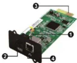
① Ethernet port (10/100Base-T)
②Sensor port
③Golden finger: connects to UPS slot
④Ethernet port status LEDs
SNMP I
SNMP II (Only for 3-phase online UPS)

① Ethernet port(10/100Base-T)
②RS-232 port
③5Vdc DC input
④ Data receiving indicator
⑤ Data transmission indicator
⑥Power indicator
Ethernet port status LEDs:
| 100M LED (Green) | Flash | Port is operating at 100Mbit/s |
| Off | Card is not connected to the network | |
| 10M LED (Yellow) | Flash | Port is operating at 10Mbit/s |
| Off | Card is not connected to the network |
1.4 Installation and Connection
Installation
If using SNMP card, please follow below steps to install SNMP card first:
Step 1: Remove the cover of intelligent slot on the back panel of UPS and retain the screws
Step 2: Slide the card into the open slot and secure with the screws from step 1. (see chart 1-1)
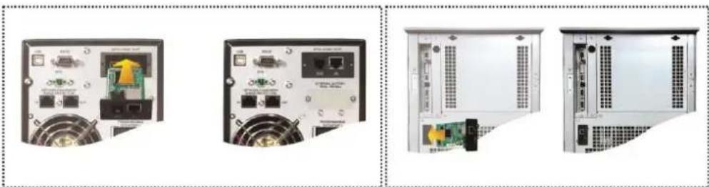
natural_image
Four-panel image showing front and back views of a server rack unit with ports, connectors, and ventilation (no visible text or labels)Chart 1-1
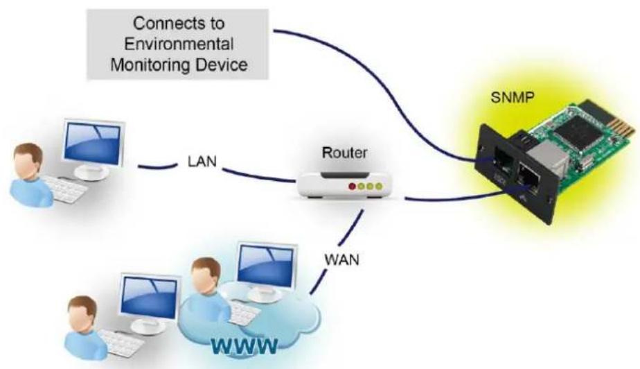
Refer to chart 1-2 for connecting the SNMP web card and chart 1-3 for connecting SNMP box.
If using SNMP card:
Plug Ethernet cable to the Ethernet port (RJ-45) on the SNMP card. Use one more Ethernet cable. Connect one end to the sensor port on the SNMP card and the other end to the optional environmental monitoring device.
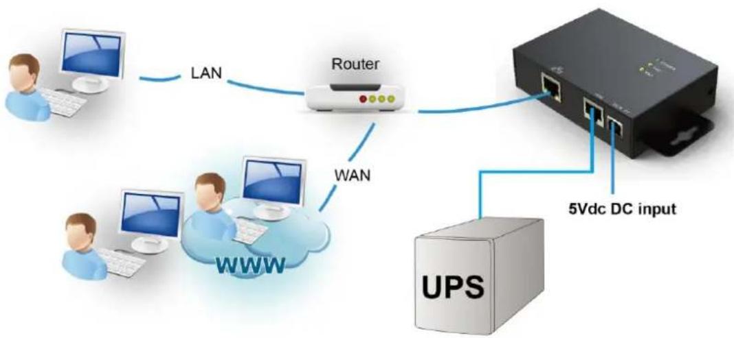
If using SNMP box:
Use one Ethernet cable to connect to Ethernet port (①) of the box. Use one RJ45 cable to connect to RS-232 port (②) of the box and RS-232 port of the UPS. Then, use bundled USB cable to connect to USB port (③) of the box and 5V DC USB power source.
flowchart
graph TD
    A["Connects to Environmental Monitoring Device"] --> B["LAN"]
    B --> C["Router"]
    C --> D["SNMP"]
    D --> E["WWW"]
    C --> F["WAN"]
Chart 1-2
flowchart
graph TD
    A["User"] -->|LAN| B["Router"]
    C["User"] -->|WAN| B
    B --> D["UPS"]
    D -->|5Vdc DC input| E["Server"]
    style A fill:#cce5ff,stroke:#333
    style C fill:#cce5ff,stroke:#333
    style B fill:#e6f3ff,stroke:#333
    style D fill:#cccccc,stroke:#333
    style E fill:#ffffff,stroke:#333
Chart 1-3
1.5 Configuration
a) Please install SNMP web manager wizard in your PC. After software is installed successfully, the Installer will leave a shortcut icon on your desktop.

Chart 1-4
b) Enter specific IP address to search all SNMP devices in LAN. (The
SNMP web manager will automatically collect the IP address from sever by default via a DHCP server. It will apply default IP address of 192.168.102.230, default subnet mask as 255.255.255.0, and default gateway as 0.0.0.0 without a DHCP server.
![SIMP Web Manager System Settings Language Help IP address MAC address 192.168.107.79 00-00-5E-00-10-23 SIMP status: 1 SIMP reset enable Use system time: 06/17/2012 16:42:01 Apply 192.168.107 Scan Add Del Basic Info IP settings Online upgrade System manager Static trap address IP address 192.168.107.79 MAC address 00-00-5E-00-10-23 Output window [16:42:00] 192.168.107.79 Online successfully.](/content/2026/06/1199341/images/3b7fcf001e9e67fd2c9790f6b6e1b9323e74557a04e36c0de242a4da46ba9e46.jpg)
Chart 1-5
c) User can modify IP setting, online upgrade, password management, and static trap address setting in SNMP Web Manager interface. It is necessary to enter password for any medications. The default password is 12345678.
Please check SNMP Web Manager User Manual for detailed configuration.
1.6 Monitoring
There are two ways to monitor:
a) Double click the selected device from the device list (refer to Chart 1-5) to open web page as Chart 1-6.
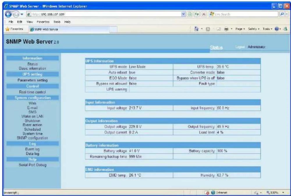
Chart 1-6
b) Installed ViewPower Pro software to monitor SNMP web card. Refer to Chart 1-7.
Please check ViewPower Pro User Manual for detailed monitoring.

Chart 1-7
2. SNMP web card GUI
SNMP web card GUI includes function menu, login section and main screen. Refer to Chart 2-1:

Chart 2-1
A .SNMP web card GUI version
B .Function Menu
It offers complete tool-set for navigation and setting the GUI.
C. Main Screen
It will display information and/or control alternatives according to function menu selected.
D. Login section
It shows user type for current login user. The default password for administrator is "12345678".
3. Function Menu
3.1 Information
3.1.1. Status
Select Information >> Status. Refer to Chart 3-1. It's shown real-time monitored UPS data including input, output, UPS, battery information and environmental information in table format.
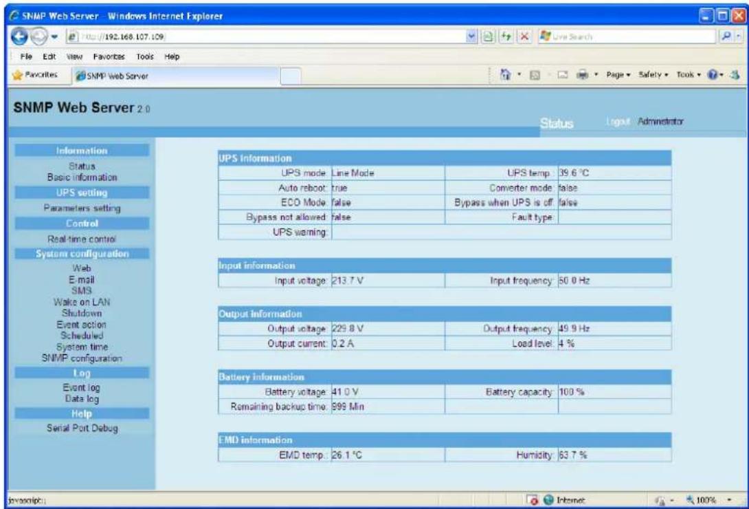
Chart 3-1
3.1.2. Basic information
Select Information>>Basic information. It includes UPS basic information, battery information and UPS rated information. Refer to Chart 3-2.
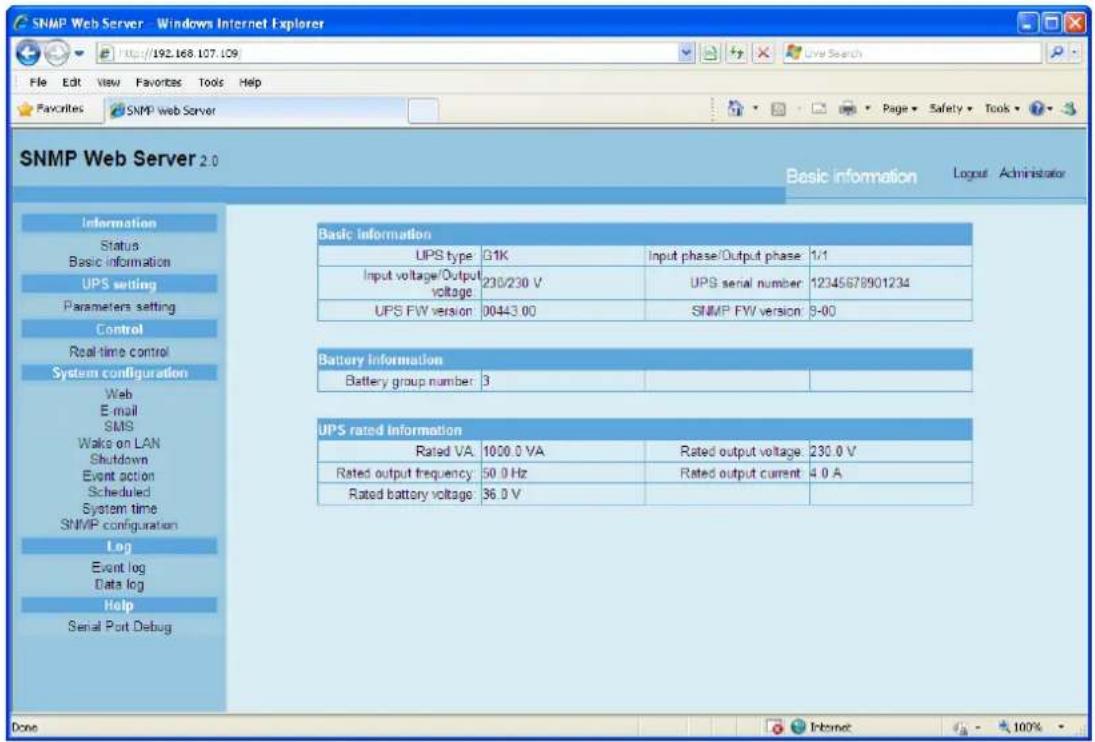
Chart 3-2
3.2 UPS setting
3.2.1 Parameters setting
Some UPS functions can be set and changed via software. Parameter setting includes backup time setting for programmable outlet (P1), battery number setting, voltage and frequency range setting for bypass mode and voltage range setting for ECO mode.
Select UPS setting >> Parameters setting. Refer to Chart 3-4.

Chart 3-4
Note: Different UPSs may access different parameter setting.
- Select the functions by clicking "Enable" or "Disable" button. Change the numbers by clicking up-down arrows or modify the numbers directly in the number column.
- Click "Apply" button to save the settings. Each function setting is saved by clicking "Apply" button in each section.
- Click "Default" button to recover the default setting.
Note: Any functions which are not supported by UPS will not be able to access.
➢ Alarm Control: If enabled, UPS alarm will be activated. Vice versa.
Alarm at bypass mode: If enabled, UPS alarms when it's working at bypass mode. Vice versa.
Alarm at battery mode: If disabled, UPS will not alarm when it's working at battery mode. Vice versa.
Auto reboot: If enabled, UPS will auto recover when AC is recovering. Vice versa.
Bypass when UPS is off: If enabled, AC will directly provide power to connected devices when UPS is off. Vice versa.
Converter mode: If enabled, the UPS will operate in converter mode. Vice versa.
ECO mode: If enabled, the UPS will operate in ECO mode when input voltage is within acceptable range. Vice versa.
Battery open status check: If enabled, the monitored UPS will check if the battery connection is ok or not when UPS is turned on.
➢ Cold start: If disabled, the UPS can be turned on only when AC is normally connected to UPS. Vice versa.
Bypass not allowed: If enabled, the UPS will not transfer to bypass mode under any conditions. If disabled, the UPS will be allowed to transfer to bypass mode according to UPS internal setting.
Battery deep-discharge protection: If enabled, the monitored UPS shuts down in accordance with the condition of battery and load on battery mode to protect battery. Vice versa.
Site fault detection: If enabled, the monitored UPS will beep when the input neutral and hot wires are reversed. Vice versa.
P1 Programmable outlet control (battery mode): If enabled, when UPS is running at battery mode, it will cut off P1 outlets after backup setting time arrives. If disabled, UPS will provide continuous power to P1 outlets until the battery is running out.
➢ Outlet setting: Users can set limited backup time for P1 outlets when UPS is on battery mode.
➢ Battery numbers setting: Set battery numbers in parallel.
Voltage and frequency range for bypass mode: Set acceptable voltage and frequency range in bypass mode
Maximum and minimum voltage: When UPS is on bypass mode and input voltage is out of setting range, UPS will enter battery mode.
✿ Maximum and minimum frequency: When UPS is on bypass mode and input frequency is out of setting range, UPS will enter battery mode.
Voltage range for ECO mode: Set acceptable voltage range for ECO mode.
3.3 Control
3.3.1. Real-time control
Select Control >> Real-time control. Refer to Chart 3-5.
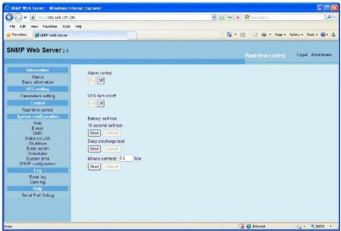
Chart 3-5
You can real-time control the UPS by executing following operation:
UPS turn On/Off: Click "On" to turn on the UPS and "Off" to turn off the UPS immediately.
Battery Self-Test: It offers three types of battery self-test: 10-second self-test, deep discharge test, and self-defined self-test. Simply clicking "Start" button from each type. It will execute the self-test immediately.
3.4. System configuration
3.4.1. Web user
It configures the authority to access SNMP web card. Please enter access ID and password in each column. There is no any limitation to access control in default setting. Refer to Chart 3-6.

Chart 3-6
If SNMP Manager pops up with "Authentication Required" windows, please provide default values as above:
User Name: user
Password: [leave empty]

3.4.2. E-mail
It's allowed to send alarm mail by SMTP server. To use this function, the e-mail service must be correctly configured. All values in this function page are default empty. This action can't be executed without the SMTP information, e-mail account and password. Besides, the sender account should be allowed for SMTP/POP3 forwarding.
Select System Configuration >> E-mail. Refer to Chart 3-7
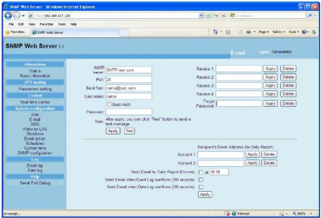
Chart 3-7
-
Enter SMTP server, SMTP port, sender's E-mail address, user name and password. Click checkbox of "Need Auth" for password verify.
-
Enter correct e-mail accounts in Receive list. Then, click "Apply" to add into receivers list. Click "Delete" button to delete e-mail account.
-
Click "Apply" to save the changes. The "Test" button can be used to send a test e-mail to all receivers to confirm correct operation. When the test e-mails are successfully sent to specific recipients, it will pop up a successful message on operated PC. Otherwise, it will pop up a failure dialog to indicate there is an error for parameter setting.
-
You may decide who will receive daily report e-mail at specific duration. Please enter recipient's Email Address and timer into columns. Then, click "Apply" button to set up this action. You also can configure who will receive alarm e-mail when event log exceeds 100 or data log exceeds 50 records. Please click checkbox of selections.
3.4.3. SMS
This function is required to have service software available such as ViewPower Pro. In the event of an alarm condition occurring, a message about UPS status will be sent to the specified users via mobile phone. Refer to Chart 3-8.
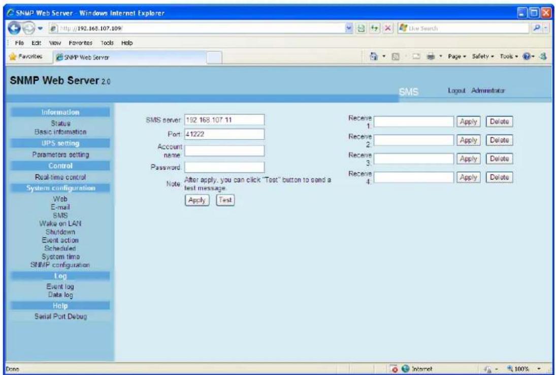
Chart 3-8
3.4.4. Wake on LAN
It's to remotely wake on specific PCs in LAN when these PCs are supported to Wake-on-LAN (WOL) via a magic packet.
Select System Configuration >> Wake on LAN. Refer to Chart 3-9.
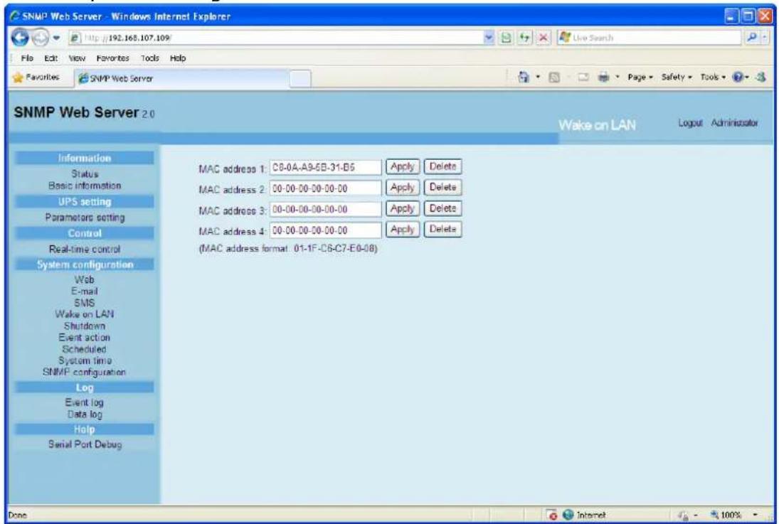
Chart 3-9
After MAC addresses of remote PCs are entered into address column, it will allow to remote control the PCs. However, it's also required to have
hardware support for remote PCs to implement this function.
3.4.5. Shutdown
It is to remotely shut down specific PCs with Shutdown Wizard. This function is only available to integrate with Shutdown Wizard. Please also check user manual of Shutdown Wizard for the details.
Select System Configuration >> Shutdown. Refer to Chart 3-10.

Chart 3-10
3.4.6. Event action
This function is only available to integrate with Shutdown Wizard. Please also check user manual of Shutdown Wizard for the details.
Select System Configuration >> Event action. Refer to Chart 3-11.
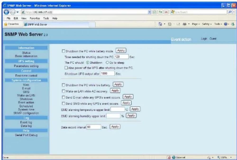
Chart 3-11
- Shutdown the PC while battery mode: When selected, integrated with Shutdown Wizard, local PC will shut down while UPS works on battery mode.
- Time needed for shutting down the PC: Enter the delay time to shut down the operating system.
-
The PC should:
-
Shutdown: When clicking the checkbox, the selected system will shut down. The default setting is clicked.
- Sleep mode: When clicking the checkbox, selected system will suspend the system instead of a normal shutdown. But this function is only supported by Windows 2000 or higher on supported hardware.
- Also power off the UPS after shutting down the PC: When click the checkbox, monitored UPS will turn off after local system shuts down. The UPS shutdown time will be later than system complete shutdown time. Users can choose to shut down the system without shutting down the UPS.
- Shutdown UPS output after xx sec: It will cut off UPS output after monitored UPS works on battery mode for xx sec.
- Shutdown the PC while low battery: When clicking this checkbox, local PC will shut down when monitored UPS battery is running low.
- Wake on LAN while AC recovery: When clicking this checkbox, the local PC will be wake on LAN while AC recovery.
- Send E-mail while any UPS event occurs: When clicking this checkbox, it will send alarm E-mail when any event occurs on the local UPS.
- Send SMS while any UPS event occurs: When clicking this checkbox, in
the event of an alarm condition occurring, a message about UPS status will be sent to the specified users via mobile phone.
- EMD alarming temperature upper limit: Set up alarm for high temperature point. If detected temperature is beyond setting value, it will send alarm message.
● EMD alarming humidity upper limit: Set up alarm for high humidity point. If detected humidity is beyond setting value, it will send alarm message.
● Data record interval xx sec: Data log record the data per xx sec.
3.4.7. Scheduled
Select System Configuration >> Scheduled. Refer to Chart 3-12.
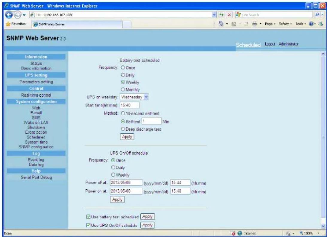
Chart 3-12
- Scheduled battery self-test: Scheduled battery self-test can be executed once, daily, weekly, or monthly. Users can select UPS and time parameters. It is recommended to set only one action in the same time. If multiple actions have been applied at the same time, some of these actions may be ignored. Any action will be ignored when the action is not supported by the UPS.
- Scheduled UPS on/off: Scheduled UPS on/off can be executed once, daily, weekly. Users can select UPS and time parameters. It is recommended to set only one action in the same time. If multiple actions have been applied at the same time, some of these actions may be
ignored. Any action will be ignored when the action is not supported by the UPS.
3.4.8. System time
Select System Configuration >> System time. Refer to Chart 3-13.

Chart 3-13
● Automatic time correction interval
● Time server: The SNTP server IP address or domain name.
● Time Zone (Relative to GMT)
- Applying daylight saving time
- System Time (mm/dd/yyyy hh:mm:ss): It is to set up SNMP web local host time
● Auto Restart system for Every (0: Disable): XX Minute(s)
- Manual Restart system after 30 Seconds.: When click "Apply" button, SNMP will restart after 30 seconds.
3.4.9. SNMP configuration
Setting SNMP web card basic information such as set IP address, password, trap IP address, SNMP UDP port and Restore the factory settings.
Note: Some operations will cause SNMP to reboot. It's normal operation.
Select System Configuration >> SNMP configuration. Refer to Chart 3-14.

Chart 3-14
- IP address: There are two methods to obtain IP address
- Automatically obtain IP address (DHCP, default)
- Manually configure IP address
The system will default automatically obtain IP addresses. If there is no this kind of service provided in LAN, the default IP will display as "192.168.102.230", Net mask as "255.255.255.0" and default gateway as "0.0.0.0".
- Password: Modify the password. The length of password is 8\~15 digits.
- Trap IP address: The SNMP device could provide 4 static trap addresses.
- SNMP UDP port: You may change SNMP port and trap port.
- Restore the factory settings
Note: The system will default automatically obtain IP addresses and default Password is 12345678.
3.5. Log
3.5.1. Event log
In the Event Log window, it lists all history events and can be saved as .csv file. The event log includes UPS warnings, fault info and EMD warnings. Refer to Chart 3-15.
Select Log >> Event log.
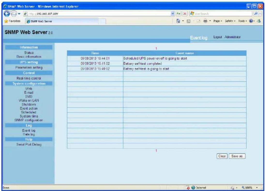
Chart 3-15
3.5.2. Data Log
In the Data Log window, it will list all history logs and can be save as .csv file. Refer to Chart 3-16.
Select Log >> Data log.
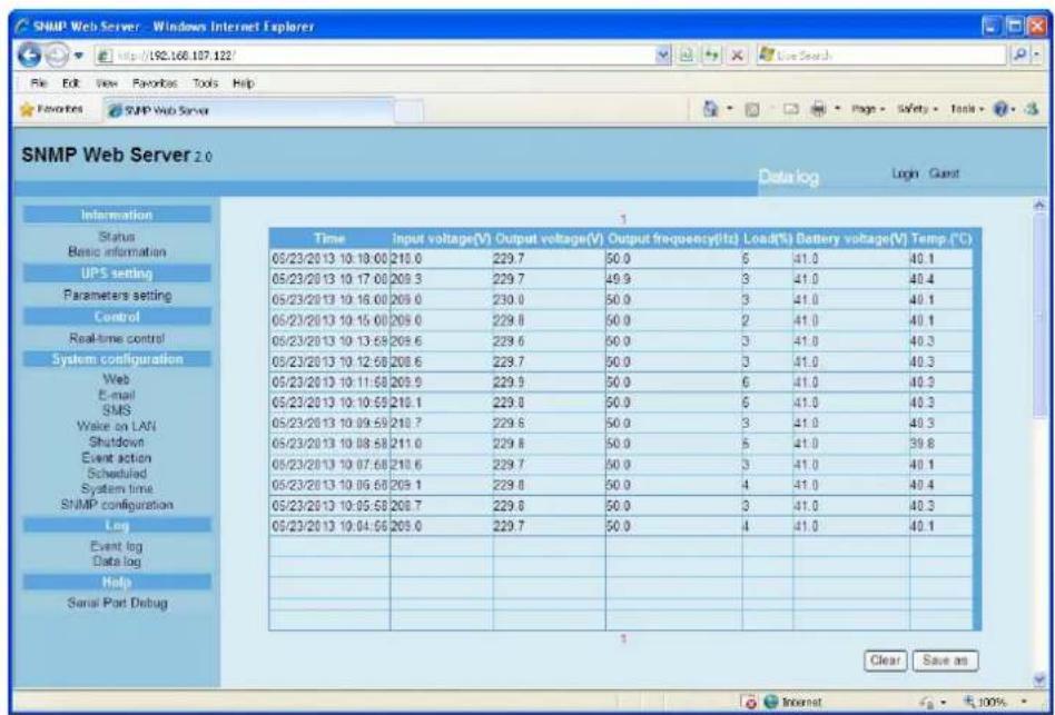
Chart 3-16
3.6. Help
3.6.1. Serial Port Debug
It's to test communication condition between SNMP card and device.
Select Log >> Event log. Refer to Chart 3-17.
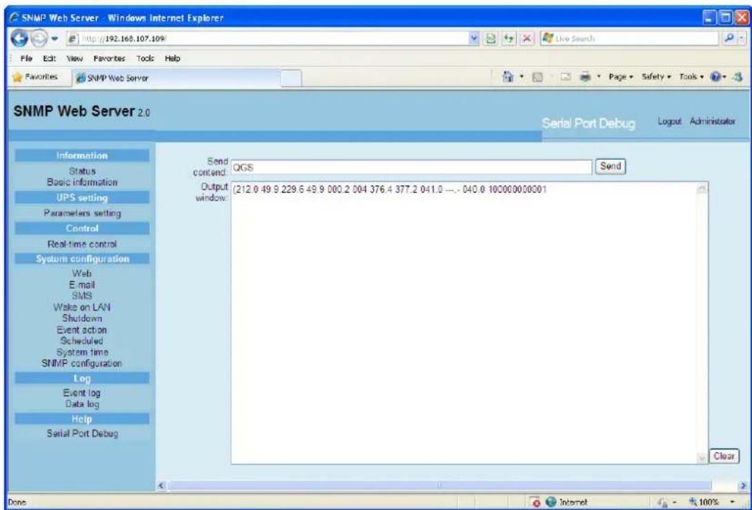
Chart 3-17


- Features
- Overlook
- Installation and Connection
- Installation
- Chart 1-1
- If using SNMP card:
- If using SNMP box:
- Configuration
- Monitoring
- SNMP web card GUI
- Function Menu
- Information
- Status
- Basic information
- UPS setting
- Parameters setting
- Control
- Real-time control
- System configuration
- Web user
- Chart 3-7
- SMS
- Wake on LAN
- Shutdown
- Event action
- Scheduled
- Chart 3-12
- System time
- SNMP configuration
- Log
- Event log
- Data Log
- Help
- Serial Port Debug
Brand : PowerPlus
Model : SNMP Web Management
Category : Unspecified