
BDHR26K - Hammer BLACK & DECKER - Free user manual and instructions
Find the device manual for free BDHR26K BLACK & DECKER in PDF.


| Product Type | SDS plus rotary hammer |
| Brand | Black & Decker |
| Model | BDHR26K |
| Power Input | 800 W |
| Voltage | 230 V |
| Frequency | 50 Hz |
| No-Load Speed | 0-900 RPM |
| Impact Rate | 0-4000 BPM |
| Impact Energy | 2.4 J |
| Max Drilling Capacity (Concrete) | 26 mm |
| Max Drilling Capacity (Steel) | 13 mm |
| Max Drilling Capacity (Wood) | 30 mm |
| Weight | 3.26 kg |
| Operating Modes | 3 modes: drilling, hammer drilling, chiseling |
| Sound Pressure Level | 88 dB(A) (K=3 dB(A)) |
| Sound Power Level | 99 dB(A) (K=3 dB(A)) |
| Vibration (Hammer Drilling) | 18.6 m/s² (K=1.5 m/s²) |
| Vibration (Chiseling) | 15.8 m/s² (K=1.5 m/s²) |
| Side Handle | Included, adjustable |
| Depth Stop | Adjustable |
| Overload Coupling | Yes, cuts driving force if bit jams |
| Lock-On Button | Yes, for continuous operation |
| Variable Speed Switch | Yes, speed depends on pressure |
| Double Insulated | Yes |
| Maintenance | Clean ventilation slots regularly; blow dust from housing with dry air |
Frequently Asked Questions - BDHR26K BLACK & DECKER
User questions about BDHR26K BLACK & DECKER
0 question about this device. Answer the ones you know or ask your own.
Ask a new question about this device
Download the instructions for your Hammer in PDF format for free! Find your manual BDHR26K - BLACK & DECKER and take your electronic device back in hand. On this page are published all the documents necessary for the use of your device. BDHR26K by BLACK & DECKER.
USER MANUAL BDHR26K BLACK & DECKER

natural_image
Line drawing of a mechanical drill bit with handle and screw base (no text or symbols)A

B
C

natural_image
Line drawing of a person holding a firearm, viewed from the side (no text or symbols)D
E

F
Intended use
Your BLACK+DECKER™ BDHR26K SDS plus rotary hammer is intended to drill holes in concrete, bricks, wood, and steel, light chipping, demolition applications and for carbide tipped core drilling or use for screwdriver.
Safety instructions
General power tool safety warnings

Warning! Read all safety warnings and all instructions. Failure to follow the warnings and
instructions may result in electric shock, fire and/or serious injury.
Save all warnings and instructions for future reference. The term “power tool” in the warnings refers to your mainsoperated (corded) power tool or battery-operated (cordless) power tool.
1. Work area safety
a. Keep work area clean and well lit. Cluttered or dark areas invite accidents.
b. Do not operate power tools in explosive atmospheres, such as in the presence of flammable liquids, gases or dust. Power tools create sparks which may ignite the dust or fumes.
c. Keep children and bystanders away while operating a power tool. Distractions can cause you to lose control.
2. Electrical safety
a. Power tool plugs must match the outlet. Never modify the plug in any way. Do not use any adapter plugs with earthed (grounded) power tools. Unmodified plugs and matching outlets will reduce risk of electric shock.
b. Avoid body contact with earthed or grounded surfaces such as pipes, radiators, ranges and refrigerators. There is an increased risk of electric shock if your body is earthed or grounded.
c. Do not expose power tools to rain or wet conditions. Water entering a power tool will increase the risk of electric shock.
d. Do not abuse the cord. Never use the cord for carrying, pulling or unplugging the power tool. Keep cord away from heat, oil, sharp edges or moving parts. Damaged or entangled cords increase the risk of electric shock.
e. When operating a power tool outdoors, use an extension cord suitable for outdoor use. Use of a cord suitable for outdoor use reduces the risk of electric shock.
f. If operating a power tool in a damp location is unavoidable, use a residual current device (RCD) protected supply. Use of an RCD reduces the risk of electric shock. NOTE: The term “residual current device (RCD)” may be replaced by the term “ground fault circuit interrupter (GFCI)” or “earth leakage circuit breaker (ELCB)”.
3. Personal safety
a. Stay alert, watch what you are doing and use common sense when operating a power tool. Do not use a power tool while you are tired or under the influence of drugs, alcohol or medication. A moment of inattention while operating power tools may result in serious personal injury.
b. Use personal protective equipment. Always wear eye protection. Protective equipment such as dust mask, non-skid safety shoes, hard hat, or hearing protection used for appropriate conditions will reduce personal injuries.
c. Prevent unintentional starting. Ensure the switch is in the off-position before connecting to power source and/or battery pack, picking up or carrying the tool. Carrying power tools with your finger on the switch or energising power tools that have the switch on invites accidents.
d. Remove any adjusting key or wrench before turning the power tool on. A wrench or a key left attached to a rotating part of the power tool may result in personal injury.
e. Do not overreach. Keep proper footing and balance at all times. This enables better control of the power tool in unexpected situations.
f. Dress properly. Do not wear loose clothing or jewellery. Keep your hair, clothing and gloves away from moving parts. Loose clothes, jewellery or long hair can be caught in moving parts.
g. If devices are provided for the connection of dust extraction and collection facilities, ensure these are connected and properly used. Use of dust collection can reduce dust-related hazards.
- Power tool use and care
a. Do not force the power tool. Use the correct power tool for your application. The correct power tool will do the job better and safer at the rate for which it was designed.
b. Do not use the power tool if the switch does not turn it on and off. Any power tool that cannot be controlled with the switch is dangerous and must be repaired.
c. Disconnect the plug from the power source and/or the battery pack from the power tool before making any adjustments, changing accessories, or storing power tools. Such preventive safety measures reduce the risk of starting the power tool accidentally.
d. Store idle power tools out of the reach of children and do not allow persons unfamiliar with the power tool or these instructions to operate the power tool. Power tools are dangerous in the hands of untrained users.
e. Maintain power tools. Check for misalignment or binding of moving parts, breakage of parts and any other condition that may affect the power tools operation. If damaged, have the power tool repaired before use. Many accidents are caused by poorly maintained power tools.
f. Keep cutting tools sharp and clean. Properly maintained cutting tools with sharp cutting edges are less likely to bind and are easier to control.
g. Use the power tool, accessories and tool
bits etc. in accordance with these instructions, taking into account the working conditions and the work to be performed. Use of the power tool for operations different from those intended could result in a hazardous situation.
- Service
a. Have your power tool serviced by a qualified repair person using only identical replacement parts. This will ensure that the safety of the power tool is maintained.
Hammer safety warnings
- Wear ear protectors. Exposure to noise can cause hearing loss.
- Use auxiliary handle(s), if supplied with the tool. Loss of control can cause personal injury.
- Hold power tool by insulated gripping surfaces, when performing an operation where the cutting accessory may contact hidden wiring or its own cord. Cutting accessory contacting a “live” wire may make exposed metal parts of the power tool “live” and could give the operator an electric shock.
- Never use a chisel accessory in rotary mode. The accessory will bind in the material and rotate the drill.
- Use clamps or another practical way to secure and support the workpiece to a stable platform. Holding the work by hand or against your body leaves it unstable and may lead to loss of control.
- Before drilling into walls, floors or ceilings, check for the location of wiring and pipes.
- Avoid touching the tip of the drill bit after drilling so as to avoid scalding.
- The intended use is described in this instruction manual. The use of any accessory or attachment or performance of any operation with this tool other than those recommended in this instruction manual may present a risk of personal injury and/or damage to property.
* Note: Mains voltage: When connecting to the mains, it is imperative to verify if the voltage of the mains matches that of the power tool. If the mains voltage exceeds the voltage indicated on the power tool, the user may become severely injured in an accident, and the tool may be damaged. On the contrary, if the mains voltage is lower than the voltage required by the tool, the motor may be damaged as a result. Thus, if it is not possible to verify the voltage, it is imperative not to plug in to the power source.
Safety of others
- This appliance is not intended for use by persons (including children) with reduced physical, sensory or mental capabilities, or lack of experience and knowledge, unless they have been given supervision or instruction concerning use of the appliance by a person responsible for their safety.
• Children should be supervised to ensure that they do not play with the appliance.
Other risks
Additional residual risks may arise when using the tool which may not be included in the enclosed safety warnings. These risks can arise from misuse, prolonged use etc. In spite of the application of the relevant safety regulations and the implementation of safety devices, certain risks cannot be avoided.
These are:
- Injuries caused by touching any rotating/moving parts.
- Injuries caused when changing any parts, blades or accessories.
- Injuries caused by prolonged use of a tool. When using any tool for prolonged periods ensure you take regular breaks.
- Impairment of hearing.
- Health hazards caused by breathing dust developed when using your tool (example:- working with wood, especially oak, beech and MDF.)
Labels on tool
The following symbols are shown on the tool along with the date code:

Warning! To reduce the risk of injury, the user must read the instruction manual.

Wear safety glasses or goggles when operating this tool.

Wear ear protection when operating this tool.
Position of Date Barcode (Fig. C)
The Date Code (12), which also includes the year of manufacture, is printed into the housing.
Example:
2017 XX JN
Year of manufacturing
Electrical Safety

Your tool is double insulated; therefore no earth wire is required. Be sure to check that the power supply corresponds to the voltage on the rating plate. Corresponds.
- If the supply cord is damaged, it must be replaced by the manufacturer or an authorised Black and Decker Service Centre in order to avoid a hazard.
Using an Extension Cable
If it is necessary to use an extension cable, please used an approved extension cable that fits the tool's power input specifications (please refer to the technical data). The minimum cross-sectional area of the conducting wire is 1.5 sq. mm. Cables should be untangled before reeling up.
Please refer to the following table.
| Cable cross-sectional area (mm ^2 ) Cable rated current (Ampere) | ||||||||
| 0.75 6 | ||||||||
| 1.00 10 | ||||||||
| 1.50 15 | ||||||||
| 2.50 20 | ||||||||
| 4.00 25 | ||||||||
| Cable length (m) | ||||||||
| 7.5 15 25 30 45 60 | ||||||||
| Voltage Amperes Cable rated current (Ampere) | ||||||||
| 115 | 0 - 2.0 | 6 | 6 | 6 | 6 | 6 | 10 | |
| 2.1 - 3.4 | 6 | 6 | ||||||
| 3.5 - 5.0 | 6 | 6 | ||||||
| 5.1 - 7.0 | 10 | 10 | ||||||
| 7.1 - 12.0 | 15 | 15 | ||||||
| 12.1 - 20.0 | 20 | 20 | ||||||
| 230 | 0 - 2.0 | 6 | 6 | |||||
| 2.1 - 3.4 | 6 | 6 | ||||||
| 3.5 - 5.0 | 6 | 6 | ||||||
| 5.1 - 7.0 | 10 | 10 | ||||||
| 7.1 - 12.0 | 15 | 15 | ||||||
| 12.1 - 12.0 | 20 | 20 | ||||||
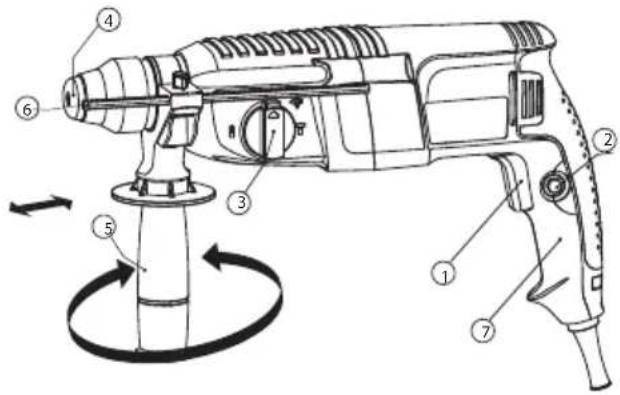
Features (Fig. E)
This tool includes some or all of the following features.
- Variable speed switch
- Lock-on button
- Mode selector
- Tool clamp
- Side handle
- Depth stop
- Main handle
Assembly
Warning! Before assembly, make sure that the tool is switched off and unplugged.
Attaching the Side Handle (fig. E)
Warning! When drilling holes in concrete or bricks, please use the side handle for your safety.
- Turn the grip counterclockwise until you can slide the side handle onto the front of the tool.
- Rotate the side handle into the desired position.
- Tighten the side handle by turning the grip clockwise.
Warning! When using the tool, remember to install the side handles properly.
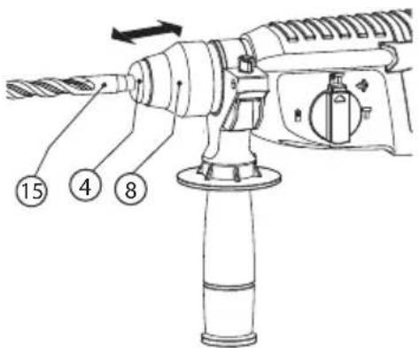
Fitting an accessory (fig.A)
- Clean and grease the shank (15) of the accessory.
- Insert the accessory bar into the tool clamp(4).
- Push the accessory down and turn it slightly until it fits into the slots.
- Pull on the accessory to check if it is properly locked. The hammering and drilling function requires the accessory to be able to move axially several centimetres when locked in the tool clamp.
- To remove the accessory, pull back the sleeve (8) and pull out the accessory from the tool clamp.
Use
Warning! Please operate tool with normal load. Do not overload.
Warning! Before drilling into walls, floors or ceilings, check for the location of wiring and pipes.
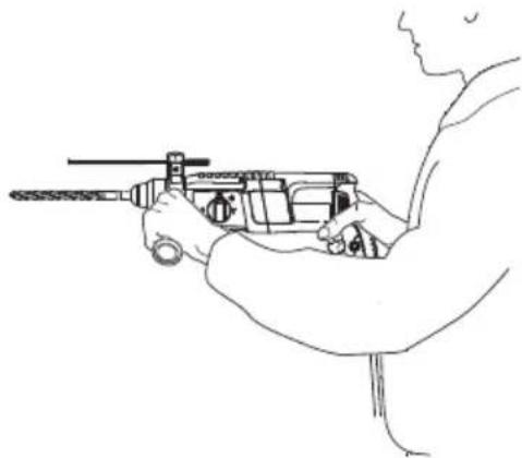
Proper Hand Position (FIG. E, FIG. D)

WARNING! To reduce the risk of serious personal injury, ALWAYS use proper hand position as shown.

WARNING! To reduce the risk of serious personal injury, ALWAYS hold securely in anticipation of a sudden reaction.
Proper hand position requires one hand on the side handle (5), with the other hand on the main handle (7).
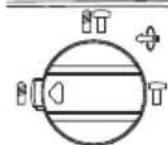
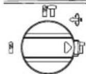
Selecting the Operating Mode (fig. B)
The tool can be used in two operating modes. Based on actual work requirements, the drilling mode selector (3) can be rotated to the required position.
Hole drilling (Fig. B) (Fig. F)
- For drilling in steel, wood and plastics, set the operating mode selector (3) to the (1) position. At the same time, it is necessary to use a suitable drill chuck (13) (optional accessory) to clamp the attachment rod.
- Insert the drill chuck (13) into the tool chuck (4) according to the instructions for installing attachments. Turn the drill chuck to loosen the clamps at the front -end of the drillclamp, and insert the accessory bar (14) into the clamps and turn the chuck in the opposite direction. You may also use the drill chuck key to tighten the clamp.
Hammer drilling (Fig. B)
- For hammer drilling in masonry and concrete, set the operating mode selector (3) to the T1 position.
- The drill bit has to be placed accurately onto the drill hole position. After that, pull the switch for optimal effects. Make sure the tool is in the correct position to prevent the drill from deviating from the hole.
- When the drill hole is clogged with debris or fine powder, please don't exert any more pressure. Tool should be put in free-running state before removing part of the drill bit from the hole. If repeated a few times, the blockage in the hole would be cleared, and normal drilling can resume.
Only impact (Fig.B)
- When chisel/peel/dismantle. turn the Mode selector (3) to “☐”. Need tip bid, cold chisel, scaling chisel and so on. Note: Don’t change the Mode selector when the tool is running.
- Repeatedly adjustment can position the Chisel Angle
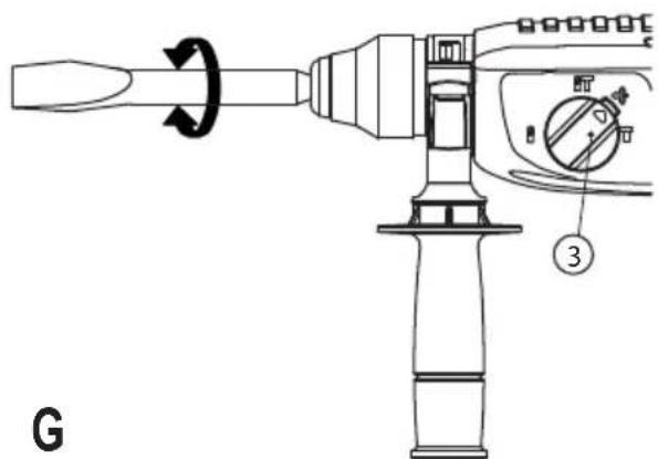
Deflection angle (chisel/peel/dismantle) (Fig.G)
- The drill head can fix different angles. Change the angle, turn the Mode selector (3) to “☐”. then turn the drill head to need angle.
Warning! When the drill bit hits cement or the steel rebar in the cement, the tool may recoil dangerously. Please hold the tool tightly in a balanced and stable position at all times to prevent it from recoiling dangerously.
Overload coupling device
If the drill bit his caught or hooked, the driving force transmitted to the drill shaft will be cut off. This would generate a strong recoil, so it would be necessary to hold the tool tightly with both hands to remain in a stable position.
Setting the drilling depth (Fig. E)
The depth stop is a convenient feature to ensure uniformity in drilling depth. Loosen the side handle to adjust the depth gauge according to the required depth. After that, tighten the side handle.
- Slacken the side handle (5) by turning the grip counterclockwise.
- Set the depth stop (6) to the required position. The maximum drilling depth is equal to the distance between the tip of the drill bit and the front end of the depth stop.
- Tighten the side handle by turning the grip clockwise.
Switching on and off
Warning! Before plugging in to the power source, make sure the switch can be flipped freely, and can return to its original position once released.
- To switch the tool on, press the variable speed switch (1). The tool speed depends on how far you press the switch.
- As a general rule, use low speeds for large diameter drill bits and high speeds for smaller diameter drill bits.
- For continuous operation, press the lock-on button (2) and release the variable speed switch.
- To switch the tool off, release the variable speed switch. To switch the tool off when in continuous operation, press the variable speed switch once more and release it.
Accessories
The performance of your tool depends on the accessory used. BLACK+DECKER accessories are engineered to high quality standards and designed to enhance the performance of your tool. By using these accessories you will get the very best from your tool.
Maintenance
Your BLACK+DECKER corded/cordless appliance/tool has been designed to operate over a long period of time with a minimum of maintenance. To ensure satisfactory operations, the tool must be maintained and cleaned regularly
Warning! Before performing any maintenance on corded/ cordless power tools:
- Switch off and unplug the appliance/tool.
- Or switch off and remove the battery from the appliance/tool if the appliance/tool has a separate battery pack.
- Or run the battery down completely if it is integral and then switch off.
- Unplug the charger before cleaning it. Your charger does not require any maintenance apart from regular cleaning.
- Regularly clean the ventilation slots in your appliance/tool/charger using a soft brush or dry cloth.
- Regularly clean the motor housing using a damp cloth. Do not use any abrasive or solvent-based cleaner.
- Regularly open the chuck and tap it to remove any dust from the interior (when

Cleaning

Warning! Blow dirt and dust out of the main housing with dry air as often as dirt is seen collecting in and around the air vents. Wear approved eye protection and approved dust mask when performing this procedure.

Warning! Never use solvents or other harsh chemicals for cleaning the non-metallic parts of the tool. These chemicals may weaken the material of the parts. Use only mild soap and damp cloth to clean the tool. Never let any liquid get inside the tool; never immerse any part of the tool into liquid.
Protecting the environment

Separate collection. This product must not be disposed of with normal household waste.
Should you find one day that your BLACK+DECKER product needs replacement, or if it is of no further use to you, do not dispose of it with household waste. Make this product available for separate collection.

Separate collection of used products and packaging allows materials to be recycled and used again. Reuse of
recycled materials helps prevent environmental pollution and reduces the demand for raw materials.
Local regulations may provide for separate collection of electrical products from the household, at municipal waste sites or by the retailer when you purchase a new product.
BLACK+DECKER provides a facility for the collection and recycling of BLACK+DECKER products once they have reached the end of their working life. To take advantage of this service please return your product to any authorised repair agent who will collect them on our behalf.
You can check the location of your nearest authorised repair agent by contacting your local BLACK+DECKER office at the address indicated in this manual. Alternatively, a list of authorised BLACK+DECKER repair agents and full details of our after-sales service and contacts are available on the Internet at: www.2helpU.com.
Service Information
BLACK+DECKER offers a full network of company-owned and authorized service locations throughout Asia. All BLACK+DECKER Service Centers are staffed with trained personnel to provide customers with efficient and reliable product service.
Whether you need technical advice, repair, or genuine factory replacement parts, contact the BLACK+DECKER location nearest to you.
NOTE
- BLACK+DECKER's policy is one of continuous improvement to our products and, as such, we reserve the right to change product specifications without prior notice.
- Standard equipment and accessories may vary by country.
- Product specifications may differ by country.
- Complete product range may not be available in all countries. Contact your local BLACK+DECKER dealers for range availability
Technical data
| BDHR26K | |
| Power input W 800 | |
| Voltage V 230 | |
| Frequency Hz 50 | |
| No-load speed min ^-1 O-900 (RPM) | |
| Impact rate BPM 0-4000 | |
| Impact energy J 2.4 | |
| Modes 3 | |
| Max drilling capacity | |
| Concrete mm 26 | |
| Steel mm 13 | |
| Wood mm 30 | |
| Weight kg 3.26 |
Level of sound pressure according to EN 60745:
Sound pressure ( L_pA ) 88 dB(A), uncertainty (K) 3 dB(A) Sound power ( L_WA ) 99 dB(A), uncertainty (K) 3 dB(A)
Vibration total values (triax vector sum) according to EN 60745:
ah, HD = 18,6 m/s ^2 , uncertainty (K) 1.5 m/s ^2 ah, Cheq = 15,8 m/s ^2 , uncertainty (K) 1.5 m/s ^2
EC declaration of conformity MACHINERY DIRECTIVE
CE
BDHR26K - Rotary Hammer
BLACK+DECKER declares that these products described under "Technical data" are in compliance with: 2006/42/EC, EN 60745-1:2009 + A11:2010, EN 60745-2-6:2010
These products also comply with Directive 2014/30/EU and 2011/65/EU.
For more information, please contact BLACK+DECKER at the following address or refer to the back of the manual.
The undersigned is responsible for compilation of the technical file and makes this declaration on behalf of BLACK+DECKER.

R. Laverick
Engineering Manager BLACK+DECKER Europe, 210 Bath Road, Slough, Berkshire, SL1 3YD United Kingdom 07.2017
Guarantee
BLACK+DECKER is confident of the quality of its products and offers an outstanding guarantee. This guarantee statement is in addition to and in no way prejudices your statutory rights.
If a BLACK+DECKER product becomes defective due to faulty materials, workmanship or lack of conformity, within 24 months from the date of purchase, BLACK+DECKER guarantees to replace defective parts, repair products subjected to fair wear and tear or replace such products to make sure of the minimum inconvenience to the customer unless:
- The product has been used for trade, professional or hire purposes.
- The product has been subjected to misuse or neglect.
- The product has sustained damage through foreign objects, substances or accidents.
- Repairs have been attempted by persons other than authorised repair agents or BLACK+DECKER service staff.
To claim on the guarantee, you will need to submit proof of purchase to the seller or an authorised repair agent. You can check the location of your nearest authorised repair agent by contacting your local BLACK+DECKER office at the address indicated in this manual. Alternatively, a list of authorised BLACK+DECKER repair agents and full details of our aftersales service and contacts are available on the Internet at: www.2helpU.com
Kullanım amacı


- Intended use
- Safety instructions
- General power tool safety warnings
- Work area safety
- Electrical safety
- Personal safety
- Hammer safety warnings
- Safety of others
- Other risks
- These are:
- Labels on tool
- Position of Date Barcode (Fig. C)
- Electrical Safety
- Using an Extension Cable
- Features (Fig. E)
- Assembly
- Attaching the Side Handle (fig. E)
- Fitting an accessory (fig.A)
- Use
- Proper Hand Position (FIG. E, FIG. D)
- Selecting the Operating Mode (fig. B)
- Hole drilling (Fig. B) (Fig. F)
- Hammer drilling (Fig. B)
- Only impact (Fig.B)
- Deflection angle (chisel/peel/dismantle) (Fig.G)
- Overload coupling device
- Setting the drilling depth (Fig. E)
- Switching on and off
- Accessories
- Maintenance
- Cleaning
- Protecting the environment
- Service Information
- NOTE
- Level of sound pressure according to EN 60745:
- Vibration total values (triax vector sum) according to EN 60745:
- EC declaration of conformity MACHINERY DIRECTIVE
- CE
- BDHR26K - Rotary Hammer
- Laverick
- Guarantee
- Kullanım amacı
Brand : BLACK & DECKER
Model : BDHR26K
Category : Hammer