
TD40 NTSC - Monitor INFOCUS - Free user manual and instructions
Find the device manual for free TD40 NTSC INFOCUS in PDF.

User questions about TD40 NTSC INFOCUS
0 question about this device. Answer the ones you know or ask your own.
Ask a new question about this device
Download the instructions for your Monitor in PDF format for free! Find your manual TD40 NTSC - INFOCUS and take your electronic device back in hand. On this page are published all the documents necessary for the use of your device. TD40 NTSC by INFOCUS.
USER MANUAL TD40 NTSC INFOCUS
Foreword
■ Caution 3
■ Important Safety Information .... 5
Overviewing your the Monitor
■ Viewing the Control Panel 9
■ Viewing the Connecting Panel .... 10
■ Viewing the Remote Control
- Key Description .... 12
- PIP(Picture In Picture) Keys .... 13
- Loading the Batteries .... 15
Installation
■ Table Stand Installation 16
■ Speaker Installation .... 17
Connecting the Cable/Devices
■ Connecting the TV Cable 18
■ Connecting the VCR 19
■ Connecting the DVD 20
■ Connecting the Set Top Box....21
■ Connecting the PC (D-Sub & DVI) 22
- Displayable the Monitor Specification.... 23
Setting the Channel
■ Basic Operation 24
■ OSD Menu Structure 25
■ Choosing the Channel Type 26
■ Storing the Channel Automatically 26
■ Fine Tuning the Channel Reception....27
■ Setting the Favorite Channel 28
Setting the Picture
■ Changing the Picture Mode 29
■ Adjusting the User Mode.... 30
■ Changing the Color Temperature 32
■ Video NR (Noise Reduction) 33
■ Changing the Screen Format .... 33
■ Adjusting the PC Screen (Geometry) 35
Setting the Sound
■ Adjusting the Sound Balance 37
■ Changing the Sound Mode .... 37
■ Adjusting the User Sound Mode 38
■ Spatial Effect ...... 38
■ AVC (Auto Volume Control).... 39
■ MTS (Multichannel Television Sound) 39
Setting the Others
■ Adjusting the Transparency of the OSD Window 40
■ PIP (Picture In Picture) 40
- Changing the Size in PIP.... 40
- Choosing the Source in PIP 41
- Picture Swap in PIP 41
- Changing the Position in PIP 42
■ Other Advanced Function 42
- Set ID 43
- Setting the Blue Screen Mode 43
- Changing the OSD Language 43
- Front Key Lock in Advance 43
■ V-chip (TV Parental Guidelines) 44
Setting the Time
■ Setting the Current Time.... 47
■ Setting the On Time.... 47
■ Setting the Off Time.... 49
■ Setting the Sleep Timer 49
Troubleshooting 50
Warranty Card 51

CAUTION
RISK OF ELECTRIC SHOCK DO NOT OPEN

CAUTION : TO REDUCE THE RISK OF ELECTRIC SHOCK, DO NOT REMOVE COVER (OR BACK), NO USER-SERVICEABLE PARTS INSIDE. REFER SERVICING TO QUALIFIED SERVICE PERSONNEL.

This symbol is intended to alert the user to the presence of uninsulated "dangerous voltage" within the product's enclosure that may be of sufficient magnitude to constitute a risk of electric shock to persons.

This symbol is intended to alert the user to the presence of important operating and maintenance(servicing) instructions in the literature accompanying the appliance.
CAUTION
- TO PREVENT DAMAGE WHICH MAY RESULT IN FIRE OR SHOCK HAZARD.
- DO NOT EXPOSE THIS APPLIANCE TO RAIN OR MOISTURE.
- SHOCK HAZARD DO NOT OPEN.
CAUTION
These servicing instructions are for use by qualified service personnel only. To reduce the risk of electric shock, do not perform any servicing other than that contained in the operating instructions unless you are qualified to do so.
CAUTION
The stand is intended for use with this monitor only. Use with other products may result in injury.
WARNING
- Apparatus shall not be exposed to dripping or splashing and no objects filled with liquids, such as vases, shall be placed on the apparatus.
- This is Class B product. In a domestic environment this product may cause radio interference in which case the user may be required to take adequate measures.
- To reduce the risk of fire and electric shock, do not expose this product to rain or moisture.
FCC NOTICE
This device has been tested and found to comply with the limits for a Class B device, pursuant to Part 15 of the FCC Rules. These limits are designed to provide reasonable protection against harmful interference in home environment as well as in a commercial, industrial or business environment. This equipment can generate, use and radiate radio frequency energy and, if not installed and used in accordance with the instruction, may cause harmful interference to radio communications. However, there is no guarantee that interference will not occur in a particular installation. If this equipment does cause harmful interference to radio or television reception, which can be determined by turning the equipment off and on, the user is encouraged to try to correct the interference by one or more of the following measures:
- Reorient or relocate the receiving antenna.
- Increase the separation between the equipment and receiver.
- Connect the equipment into an outlet on a circuit different from that to which the receiver is connected.
- Consult the dealer or an experienced radio/TV technician for help.
Changes or modification not expressly approved by the party responsible for compliance could void the user's authority to operate the equipment. Connecting of peripherals requires the use of grounded shielded signal cables.
Always be careful when using your the Monitor. To reduce the risk of fire, electrical shock, and other injuries, keep these safety precautions in mind when installing, using, and maintaining your machine.

natural_image
Cartoon illustration of a smiling computer monitor with a microphone and earphones (no text or symbols)Read all safety and operating instructions before operating your the Monitor.

natural_image
Cartoon illustration of a smiling computer monitor with a magnifying glass showing a grid of books (no text or symbols present)Keep the safety and operating instructions for future reference.

Heed all warnings on the Monitor and in the operating instructions.
Always be careful when using your the Monitor. To reduce the risk of fire, electrical shock, and other injuries, keep these safety precautions in mind when installing, using, and maintaining your machine.
- Read these instructions.
- Keep these instructions.
- Heed all warnings.
-
Follow all instructions.
-
Do not use this apparatus near water.
-
Clean only with a damp cloth.
-
Do not block any of the ventilation openings. Install in accordance with the manufacturer's instructions.
-
Do not install near any heat sources such as radiators, heat registers, stoves, or other apparatus (including amplifiers) that produce heat.
-
Do not defeat the safety purpose of the polarized or grounding type plug. A polarized plug has two blades with one wider than the other. A grounding type plug has two blades and a third grounding prong. The wide blade or the third prong is provided for your safety. When the provided plug does not fit into your outlet, consult an electrician for replacement of the obsolete outlet.
-
Protect the power cord from being walked on or pinched particularly at plugs, convenience receptacles, and the point where they exit from the apparatus.
-
Only use the attachments/accessories specified by the manufacturer.
-
Use only with a cart, stand, tripod, bracket, or table specified by the manufacturer, or sold with the apparatus. When a cart is used, use caution when moving the cart/apparatus combination to avoid injury from tip-over.

natural_image
Symbolic icon of a person pushing a large box with a triangular shape, enclosed in a circle (no text or symbols)-
Unplug this apparatus during lightning storms or when unused for long periods of time.
-
Refer all servicing to qualified service personnel. Servicing is required when the apparatus has been damaged in any way, such as power supply cord or plug is damaged, liquid has been spilled or objects have fallen into the apparatus, the apparatus has been exposed to rain or moisture, does not operate normally, or has been dropped.

natural_image
Cartoon illustration of a smiling computer monitor with hands and earphones (no text or symbols)Follow all operating and use instructions.

Unplug the Monitor from the wall outlet before cleaning. Use a damp cloth; do not use liquid or aerosol cleaners.

natural_image
Cartoon illustration of a computer monitor with a butterfly graphic and a small cat, no text or symbols presentNever add any attachments and/or equipment without approval of the manufacturer. Such additions can increase the risk of fire, electric shock, or other personal injury.

natural_image
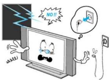
Cartoon illustration of a person reacting to a TV screen showing floating objects, surrounded by clouds and debris (no text or symbols)Do not use the Monitor where contact with or immersion in water is a possibility, such as near bath tubs, sinks, washing machines, swimming pools, etc.
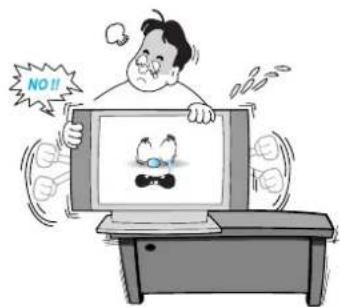
When installing the Monitor on a table, be careful not to place it too close to the edge of the table.
- This may cause the Monitor to fall, causing serious injury to a child or adult, and serious damage to the Monitor.
natural_image
Cartoon illustration of a computer monitor with a smiling face, connected to a speaker and a microphone (no text or symbols present)Provide ventilation for the Monitor. The unit is designed with slots in the cabinet for ventilation to protect it from overheating. Do not block these openings with any object, and do not place the Monitor on a bed, sofa, rug or other similar surface. Do not place it near a radiator or heat register. If you place the Monitor on a rack or bookcase, ensure that there is adequate ventilation and that you've followed the manufacturer's instructions for mounting.
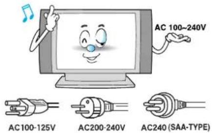
Use only the accessory cord designed for this product to prevent shock. The power supply voltage rating of this product is AC100-240V, the power cord attached conforms to the following power supply voltage. Use only the power cord designated by our dealer to ensure Safety and EMC.
When it is used by other power supply voltage, power cable must be changed. Consult your product dealer.
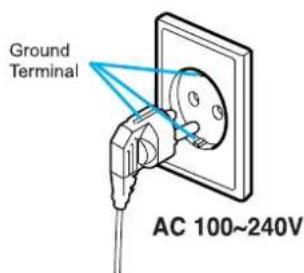
Use only a grounded or polarized outlet. For your safety, this Monitor is equipped with a polarized alternating current line plug having one blade wider than the other. This plug will fit into the power outlet only one way. If you are unable to insert the plug fully into the outlet, try reversing the plug. If the plug still does not fit, contact your electrician to replace your outlet.

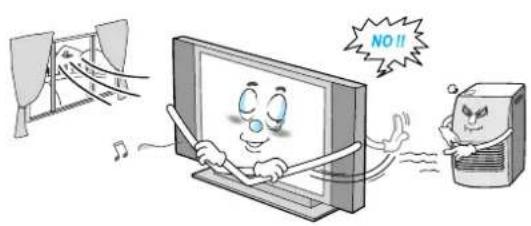
Avoid overhead power lines. An outside antenna system should not be placed in the vicinity of overhead power lines or other electric light or power circuits or where it can fall into such power lines or circuits. When installing an outside antenna system, be extremely careful to keep from touching the power lines or circuits. Contact with such lines can be fatal.
Unplug the Monitor from the wall outlet and disconnect the antenna or cable system during a lightning storm or when left unattended and unused for long periods of time. This will prevent damage to the unit due to lightning and power-line surges.

Protect the power cord. Power supply cords should be routed so that they won't be walked on or pinched by objects placed on or against them. Pay particular attention to cords at plugs, convenience receptacles, and the point where they exit from the unit.

natural_image
Illustration of an electrical circuit with a battery, wires, and a warning symbol (no text or labels)Do not overload the wall outlet or extension cords. Overloading can result in fire or electric shock.

natural_image
Cartoon illustration of a person using a computer monitor with a smiling face and musical notes (no text or symbols)Do not insert anything through the openings in the unit, where they can touch dangerous voltage points or damage parts. Never spill liquid of any kind on the Monitor.

Bend antenna cable between inside and outside building to prevent rain from flowing in.
- This may cause water damaged inside the Monitor and could give an electric shock.
Ground outdoor antennas. If an outside antenna or cable system is connected to the Monitor, be sure the antenna or cable system is grounded so as to provide some protection against voltage surges and built-up static charges. Section 810 of the National Electrical Code, ANSI/NFPA No.70-1984, provides information about proper grounding of the mast and supporting structure, grounding of the lead-in wire to an antenna discharge unit, size of grounding conductors, location of antenna discharge unit, connection to grounding electrodes, and requirements for the grounding electrode.
natural_image
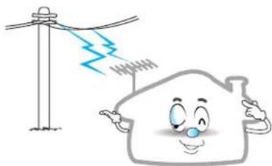
Cartoon illustration of a house with a lightning bolt above it, next to a utility pole (no text or symbols)Do not place an outside antenna in the vicinity of overhead power lines or other electric light or power circuits.
- This may cause an electric shock.

There should be enough distance between an outside antenna and power lines to keep the former from touching the latter even when the antenna falls.
- This may cause an electric shock.
Do not attempt to service the Monitor yourself. Refer all servicing to qualified service personnel. Unplug the unit from the wall outlet and refer servicing to qualified service personnel under the following conditions:
- when the power-supply cord or plug is damaged
- if liquid has been spilled on the unit or if objects have fallen into the unit
- if the Monitor has been exposed to rain or water
- if the Monitor does not operate normally by following the operating instructions
- if the Monitor has been dropped or the cabinet has been damaged
- when the Monitor exhibits a distinct change in performance

natural_image
Cartoon illustration of a man reacting to a falling stock chart on a computer screen, with a lightning bolt symbolizing market decline (no text or symbols present)When replacement parts are required, be sure the service technician uses replacement parts specified by the manufacturer or those that have the same characteristics as the original part. Unauthorized substitutions may result in additional damage to the unit.

Upon completion of any service or repairs to this the Monitor, ask the service technician to perform safety checks to determine that the Monitor is in a safe operating condition.

natural_image
Cartoon illustration of a man reacting to a falling stock chart on a computer screen, with a lightning bolt symbolizing market decline (no text or symbols present)If you make adjustments yourself, adjust only those controls that are covered by the operating instructions. Adjusting other controls may result in damage and will often require extensive work by a qualified technician to restore the Monitor to normal.
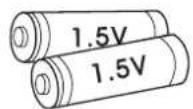
Only use the specified batteries.
- This may cause damage to the Monitor or could give an electric shock.

natural_image
Cartoon illustration of a computer monitor with a surprised face and speech bubbles (no text or symbols)Do not place anything containing liquid on top of the Monitor.
- This may cause a fire or could give an electric shock.

natural_image
Cartoon illustration of a smiling television with smoke and flames, accompanied by a grape cluster (no text or symbols)In case of smoke or strange smell from the Monitor, switch it off, unplug it from the wall outlet and contact your dealer or service center.
- This may cause a fire or could give an electric shock.

natural_image
Cartoon illustration of a person reacting to a screen showing two butterflies (no text or symbols present)The viewing distance should be about 5\~7 times as long as diagonal length of the screen.
- If not, eyes will strain.

natural_image
Cartoon illustration of a person reacting to a surprised expression on a computer monitor (no text or symbols present)When moving the Monitor assembled with speakers do not carry holding the speakers.
- This may cause the Monitor to fall, causing serious injury to a child or adult, and serious damage to the Monitor.
OSD Key Position
Front Panel
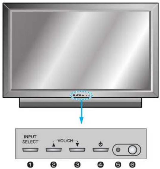
OSD key & Function
① Input Source Select
2 UP
③ DOWN (See the box below.)
4 Power (Stand By)
5 Remote Sensor
6 Status / Power Indicator LED
OSD Key Function
INPUT SELECT
Select the signal source from multiple input sources such as TV, AV 1, AV 2, S-Video / AV, Component1, Component2, PC and DVI.
VOL/CH▲/▼
To change the CHANNEL, Press ▲ button first and change the CHANNEL with ▲,▼ buttons. To change the VOLUME, Press ▼ button first and change the VOLUME with ▲,▼ buttons.
Power On /Off
Turn the Monitor on and off.
Accessories
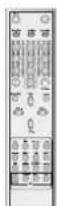
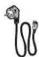
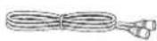

Remote Control Handset Power Cord RF Cable Owner's Manual Alkaline Batteries
Back Panel and Jacks
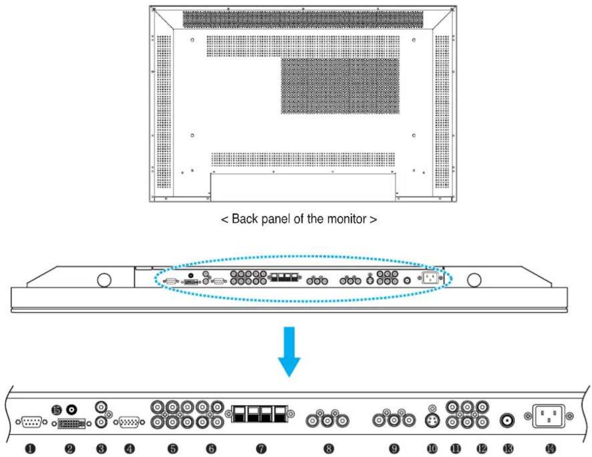
| 1 | RS-232C | To control from PC. |
| 2 | DVI | For PC, Set top box. |
| 3 | PC Sound | PC/DVI Audio Input. |
| 4 | D-Sub (PC) | For PC, Set top box. |
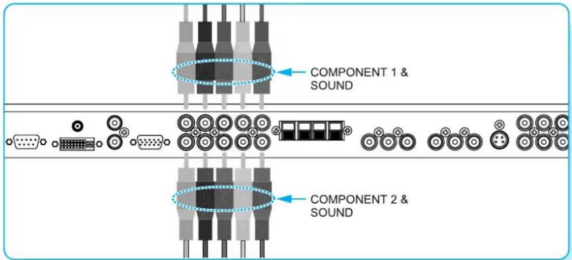
| 5 | Component 1, 2 | For DVD, Set top box. |
| 6 | Component Sound | For Component Audio Input. |
| 7 | Speakers | To connect speakers (2CH, Stereo) |
| 8 | AV 1 | For VCR, DVD, Set top box. |
| 9 | AV 2 | For VCR, DVD, Set top box. |
| 10 | S-Video | For DVD, Set top box, S-VHS. |
| 11 | AV Output | To connect other TV or monitor. |
| 12 | AV 3 | For VCR, DVD, Set top box. |
| 13 | TV Antenna | For TV antenna cable. (Air) |
| 14 | AC Power | |
| 15 | DC 5V Output |
① RS-232C Jack
Connects a control signal from a PC.
② DVI Input Jack
Connects a digital video signal from a DVI output jack of PC or Set Top box.
③ PC Sound
Connects a sound signal from PC or DVI.
④ RGB PC Input Jack (D-Sub)
Connects a video signal from a video output jack of PC.
Cables connecting the PC vary according to the type of machine, so contact your product dealer.
⑤ Component Input Jack 1, 2
Connects a three separate component video signal from a component output jack of a DVD player or Set Top box.
Supports 480i/60Hz, 480p/60Hz, 576i/50Hz, 576p/50Hz, 720p/60Hz, 720p/50Hz, 1080i/50Hz, 1080i/60Hz signals. (i: interlace, p: progressive)
6 Component Sound
Connects a sound signal from component.
⑦ Speaker Jack
Connects external speakers by wires. Match red/red and black/black of speaker/TV.
⑧ ⑨ Composite (RCA) input Jack 1, 2
Connects an AV composite video signal from a composite output terminal of a VCR or DVD player.
⑩ S-Video Input Jack
Connects a S-Video video signals from a S-Video output jack of a S-VHS, VCR or DVD player.
⑪ (Upper). Composite (RCA) output Jack
Output the signal of the current screen of the Monitor. Connects to other TV or monitor.
⑫ (Lower). Composite (RCA) input Jack 3
Connects an AV composite video signal from a composite output terminal of a VCR or DVD player. Unavailable when a S-Video cable is put into the S-Video input jack.
⑬ ANT. IN (TV Antenna Jack)
Connects to an TV antenna cable.
14 AC(POWER) Input Terminal
Firmly insert the accessory power cord as far as it will go into the power input terminal. Firmly push the power cord plug as far as it will go into the power socket.
Connectors
| AUDIO INPUT | RCA Pin Jack |
| COMPOSITE VIDEO INPUT | RCA Pin Jack |
| COMPOSITE VIDEO OUTPUT | RCA Pin Jack |
| S-VIDEO INPUT | Mini Din 4 Pin |
| COMPONENT VIDEO INPUT | RCA Pin Jack |
| ANALOG RGB INPUT | Mini D-Sub 15pin |
| DIGITAL VIDEO INPUT | DVI-D 24 pin |
- Cables connecting the PC vary according to the type of machine, so consult your product dealer.
RS-232C Configurations
3-Wire (Non-standard)
 | ||
| RXD | 2 | 3 |
| TXD | 3 | 2 |
| GND | 5 | 5 |
| DTR | 4 | 4 |
| DSR | 6 | 6 |
| RTS | 7 | 7 |
| CTS | 8 | 8 |
Key Description
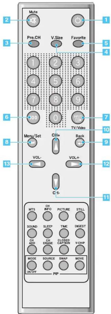
1 Power
Turn the Monitor on and off.
2 Mute
Temporarily cut the sound and restore it.
3 Pre.CH
Turn to the previous channel or exit OSD.
4 V.Size Choose the Screen Form. Wide Panorama Zoom1 Zoom2 4:3
5 FAVORITE (FAVOURITE)
Tune to your next favorite channel.
6 100
Press to tune the channels over 100.
7 INPUT
Display the input source list.
8 Menu / Set
Display the main OSD menu.
Activate your choice in the OSD menu.
9 Back
Return to the previous OSD menu.
10 CH+
Move to the upper channel.
11 CH- Move to the lower channel.
12 VOL+
Increase the volume level.
13 VOL- Decrease the volume level.
PIP (Picture In Picture) Keys
13 MODE (On / Off)
Activate PIP function and change the PIP window size and PIP mode.
Small → Large → Twin (Half) → OFF
14 SOURCE
Change the PIP window source.
15 SWAP
Swap the main screen and the PIP window.
16 MOVE
Move the position of the PIP window.
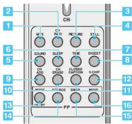
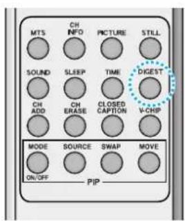
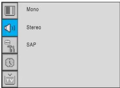
1 MTS
Choose the MTS (Stereo) mode. Each time it is pressed, different mode is selected.
Mono → Stereo → SAP
- You can select only available modes depending on the source.
2 CH INFO
Display the current information about time, screen form, source and MTS mode.
3 PICTURE
There are 4 picture modes.
Standard → Vivid → Mild → User
4 STILL
Temporarily freeze the screen and restore it.
5 SOUND
Choose the sound equalizer settings.
Standard → Movie → Music → News → User
6 SLEEP
Set the preset time interval for automatic turn-off.
OFF → 10 → 20 → 30 → 60 → 90 → 120 → 150 → 180
7 TIME
Display the current time on the screen.
8 Digest
Display 15 TV programs at the same time.
9 CH ADD
Add the current channel to memory.
10 CH ERASE
Erase the current channel from memory.
11 CLOSE CAPTION
Set the close caption.
OFF → Close Caption1 → Close Caption2 → Text1
→ Text2
12 V-CHIP
Get into V-Chip menu.
flowchart
graph TD
    A["Move key: Move the position of PIP window."] --> B["Left Up"]
    B --> C["Right Up (Start)"]
    C --> D["Down"]
    D --> E["Left Down"]
    E --> F["Right Down"]
    G["Swap key: Swap the sources of the main screen and PIP window."] --> H["Image 1"]
    H --> I["Image 2"]
    I --> J["Image 3"]
    J --> K["Change from small to large to twin"]
    L["MODE KEY: Change the PIP window mode. OFF → SMALL → LARGE → TWIN"] --> M["SMALL"]
    M --> N["LARGE TWIN"]
Source key : Change the source of the PIP window. The available sources are shown as below.
| PIP\Main | TV AV 1 | AV 2 | S-Video/AV 3 | Component1 | Component2 PC | DVI | ||
| TV | √ | √ | √ | √ | √ | √ | √ | √ |
| AV 1 | √ | - | √ | √ | √ | √ | √ | √ |
| AV 2 | √ | √ | - | √ | √ | √ | √ | √ |
| S-Video/AV 3 | √ | √ | √ | - | √ | √ | √ | √ |
| Component1 | √ | √ | √ | √ | - | - | - | - |
| Component2 | √ | √ | √ | √ | - | - | - | - |
| PC | √ | √ | √ | √ | - | - | - | - |
| DVI | √ | √ | √ | √ | - | - | - | - |
Loading the Batteries
1 Press on the cover and slide in the direction of the arrow.
2 care that the + and - ends face the correct direction.
3 Close the cover until it clicks. Load two AAA batteries, taki
natural_image
Simple diagram of a device with a blue downward arrow indicating compression or disassembly (no text or symbols)
natural_image
Technical line drawing of a battery panel with two terminals and a separate view showing internal components (no text or symbols)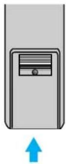
natural_image
Simple diagram of a device with a blue upward arrow indicating motion or direction (no text or symbols)Reception Range of Remote Control
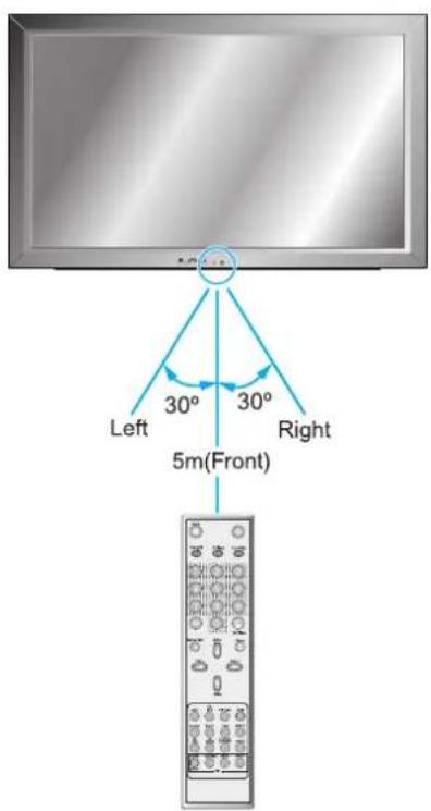
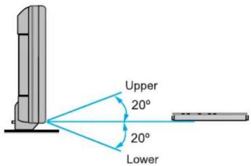
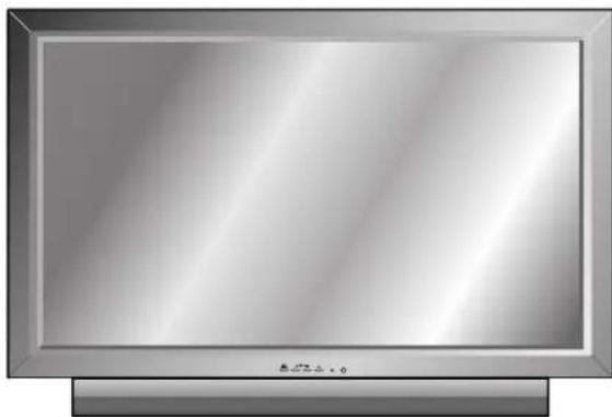
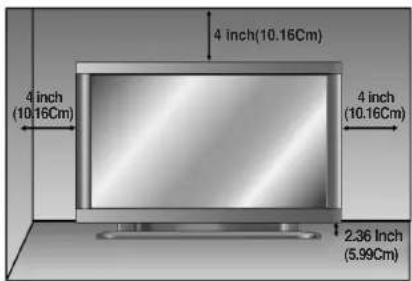
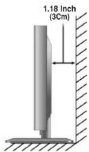
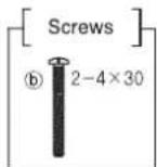
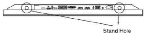
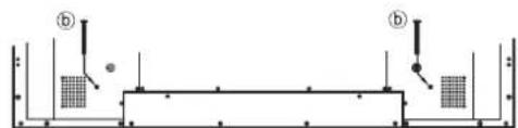
Table Stand Installation (Optional)
natural_image
Front view of a flat-screen CRT television with no visible text or symbols on the screen or frame.< The Monitor can be installed on the desk as shown above. >
- Table Stand mount minimum allowable clearances for adequate ventilation.
Installation
Table-Stand User's Guide
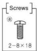
① Insert Stand Bars into the Stand Base as shown below
② a- Secure with Screw A (8 x 18)
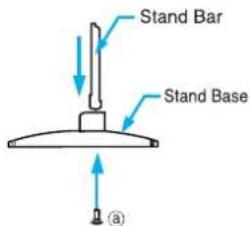
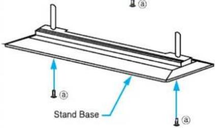
③ Insert a Stand-Table as below ④ b—Secure with Screw B (4 x 30)
natural_image
Pure structural diagram of a beam supported by two vertical supports, with no text or symbols present.
Speaker Installation (Optional)

Caution
- Be sure monitor power is turned off before making any connections.
Place the speakers in the position you want. Install the speaker wires on the monitor and speaker. Be sure to connect the positive "+" wire to the "+" input and the negative "-" wire to the "-" input. Connect left monitor input to left speaker and right monitor input to right speaker. Any extra speaker wire length remaining can be bunched into the wire holders provided.
(Caution: Once installed, the speaker wire holders lock into position and can't be removed.)
• Always lift the monitor itself (not the speakers) when handling or moving the monitor after speakers have been installed.
Speaker Accessories
4-Iron Plates (Mount speakers to monitor)
8-4 x 16 Long Bolts
(Attach iron plates to speakers)
8-4 x 8 Short Bolts
(Attach iron plates to monitor)

2-Speaker Wires
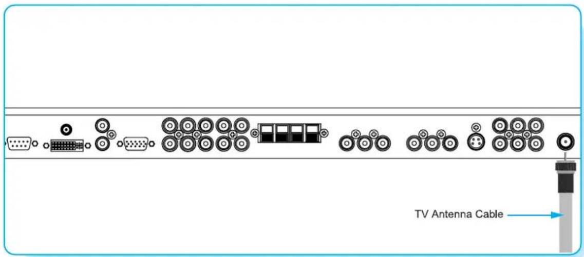
Connecting the TV Cable
1 Connect the TV antenna cable to the TV input jack. Press INPUT button on the remote control and select TV on OSD.
2 Use CH+, CH- button or numeric button to change TV channel for your channel selection.
3 Press Pre.CH button on the remote control to tune the previous channel.
4 Also, you can tune to cable service provided channels using the cable box. For further information regarding cable TV service, contact cable TV service provider(s).
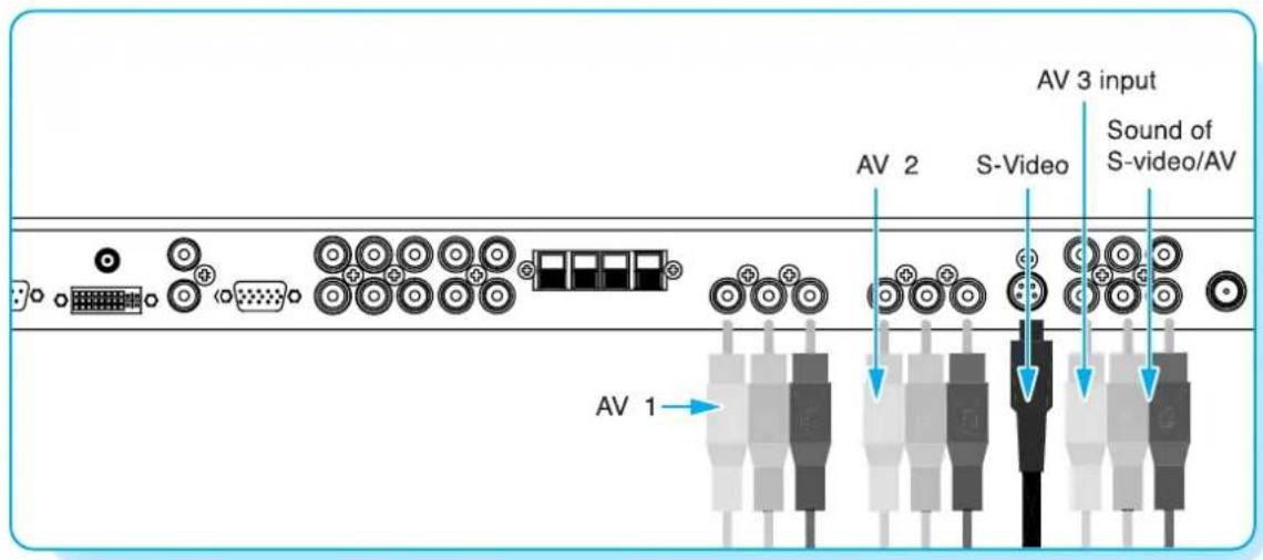
Connecting the VCR
With S-Video
Connect a S-Video cable to the S-Video jacks of the VCR and the Monitor.
Connect L (White), R (Red) sound cable (composite) to the sound jacks of the VCR and the Monitor.
With AV input
Connect a composite cable to the AV video jacks of the VCR and the Monitor.
Connect L (White), R (Red) sound cable (composite) to the sound jacks of the VCR and the Monitor.
Watching VCR
1 Press INPUT button on the remote control and select Video Sources.
2 Insert a video tape into the VCR and press the PLAY button on the VCR.

Notes
- To avoid picture noise (interference), leave an adequate distance (over 3m) between the VCR and monitor.
- When connecting the Monitor with external equipment, match the colour of connecting ports (e.g. Video -yellow, Audio(L) - white, Audio(R) - red).
- If you have a mono VCR, connect the audio cable from the VCR to the AUDIO(L/MONO) input of the Monitor.
- If you connect an S-VHS VCR to the S-VIDEO input socket, you can get a better picture quality than normal video input (AV).
Connecting the DVD
- Connect the three separate component video cables to the DVD player's Y, Pb and Pr jacks and to the Component jacks on the Monitor.
- Connect the audio cable to the DVD player's audio L (White) and R (Red) jacks and to the L and R audio jacks beside the Component jacks on the Monitor.
How to use
1 Turn on the DVD player.
2 Press INPUT button on the remote control of the Monitor and select Component1 or Component2.
Component Input ports
You can get better picture quality if you connect DVD player with component input sockets as below.
| Supported Signals for Component ports | ||
| Component1 | Component2 | |
| 480i / 60Hz | √ | √ |
| 480p / 60Hz | √ | √ |
| 576i / 50Hz | √ | √ |
| 576p / 50Hz | √ | √ |
| 720p / 50Hz | √ | √ |
| 720p / 60Hz | √ | √ |
| 1080i / 50Hz | √ | √ |
| 1080i / 60Hz | √ | √ |
| Component ports of the Monitor | Y | P_B | P_R |
| Video output ports of DVD player | Y | Pb | Pr |
| Y | B-Y | R-Y | |
| Y | Db | Cr | |
| Y | P_B | P_R |

- Normal DVD source is based on 480i, which should be through normal YPbPr of Component signal.
- Component, PC, DVI ports can be displayed only 1 signal among them. If one of them is being displayed, other ports are unavailable.
How to connect
Connect Set Top Box video inputs to AV, COMPONENT, PC or DVI jacks on the Monitor.
Audio inputs to Audio sockets beside the L (White) and R (Red) audio jacks which you connect video inputs.
natural_image
Diagram of electronic component pinout showing various connectors and connectors (no text or labels)How to use
1 Turn on the Set Top Box.
2 Press INPUT button on the remote control of the Monitor and select Component1, Component2, PC or DVI.
Supported Signals
| Component1 Component2 PC DVI | ||||
| 480i/60Hz | √ | √ | - | - |
| 480p/60Hz | √ | √ | √ | √ |
| 576i/50Hz | √ | √ | - | - |
| 576p/50Hz | √ | √ | √ | √ |
| 720p/50Hz | √ | √ | √ | √ |
| 720p/60Hz | √ | √ | √ | √ |
| 1080i/50Hz | √ | √ | √ | √ |
| 1080i/60Hz | √ | √ | √ | √ |
How to connect
With Component
Connect a three separate component cables to the component jacks of the STB and the Monitor.
Connect L (White) and R (Red) sound cables (composite) to the sound jacks of the STB and the Monitor.
With RGB(D-Sub) or DVI
Connect a D-Sub or DVI cable to the AV video jacks of the STB and the Monitor.
Connect L (White) and R (Red) sound cables (composite) to the sound jacks of the STB and the Monitor.

Notice
- Component, PC and DVI ports can be displayed only 1 signal among them. If one of them is being displayed, other sockets are unavailable.
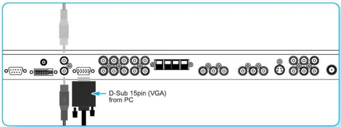
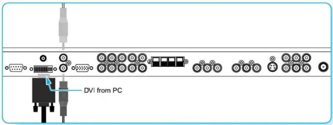
Connecting a PC to the Monitor
- There are two connectors to connect the Monitor and PC: D-Sub and DVI.
• D-Sub
Connect a PC (15pin) video cable between the Video Output port on the PC and the PC port on the Monitor.
• DVI
Connect a DVI-D cable between the DVI Output port on the PC and the DVI port on the Monitor.
Pin Configuration
15Pin Signal Cable (based on protruded pin)
To watch the PC screen
① Turn on the Monitor and press INPUT button to select the PC MODE.
② Turn on the PC and check for the PC requirements.
3 Adjust the PC screen in Geometry menu.
| Pin No. Description | |
| 1 | Red (R) |
| 2 | Green (G) |
| 3 | Blue (B) |
| 4 | Grounding |
| 5 | Grounding (DDC) |
| 6 | Red (R) Grounding |
| 7 | Green (G) Grounding |
| 8 | Blue (B) Grounding |
| 9 | Reserved |
| 10 | Sync Grounding |
| 11 | Grounding |
| 12 | Data (DDC) |
| 13 | Horizontal sync. |
| 14 | Vertical sync. |
| 15 | Clock (DDC) |
Resolution Horizontal Frequency (KHz) Vertical Frequency (Hz)
| 640 x 350 | 31.468 | 70.09 |
| 37.861 | 85.08 | |
| 640 x 400 | 31.469 | 70.08 |
| 37.927 | 85.03 | |
| 640 x 480 | 31.469 | 59.94 |
| 35.000 | 66.66 | |
| 37.861 | 72.80 | |
| 37.500 | 75.00 | |
| 43.269 | 85.00 | |
| 45.913 | 90.03 | |
| 53.011 | 100.04 | |
| 64.062 | 120.000 | |
| 800 x 600 | 35.156 | 56.25 |
| 37.879 | 60.31 | |
| 48.077 | 72.18 | |
| 46.875 | 75.00 | |
| 53.674 | 85.06 | |
| 56.000 | 90.00 | |
| 64.016 | 100.00 | |
| 832 x 624 | 49.725 | 74.55 |
| 852 x 480 | 31.468 | 60.05 |
| 1024 x 768 | 48.363 | 60.00 |
| 56.476 | 70.06 | |
| 60.023 | 75.02 | |
| 1280 x 768 | 47.700 | 60.00 |
| 1280 x 1024 | 64.000 | 60.00 |
• The PC signal is supported by DVI also.

Notes
• Synchronization input form : separate
• The Monitor recognizes 640x480@60Hz signal as 480p DTV signal. So the signal is expanded, please try other signals like 640x480@75Hz.
- The Monitor operates abnormally if a non-standard video format is selected.
- 1280 X 768 : 40" Native Resolution Horizontal Polarity is Positive(+) Vertical Polarity is Negative(-)
- Depending on the manufacturer, your PC screen might appear differently (and depending on your particular version of Windows).
Check your PC instruction book for information about connecting your PC to a the Monitor. - The Monitor may operate abnormally if a non-standard video signal.
- "Out of range" message box will appear when an over-spec video signal is input. Change the video settings of PC when the message is displayed.
Turning the Monitor On /Off
Press the Power button on the remote control. The Monitor will turn on and you will be ready to use its features. You can also use the Power button on the front panel.
Select Source
Press INPUT button on the remote control. Then you can see the source list menu shown as below.
Source Change
1 TV
2 AV 1
3 AV 2
4 S-VIDEO /AV 3
5 COMPONENT 1
6 COMPONENT 2
7 PC
8 DVI
Source list menu
Select the source to watch with CH+/CH- button on the remote control and press the Menu/Set button.
TV Channel Selection
1 Connect the signal source (TV antenna) to TV input. Press INPUT button on the remote control and select TV on the source list.
2 Use CH+, CH- button or numeric button to change TV channel you want.
3 Press Pre.CH button on the remote control to watch the previous channel.
4 Also, you can tune the cable service, provided channels while using the cable box. For further information regarding cable TV service, contact your TV service provider(s).
Volume Control
Use VOL+/VOL- button on the remote control to adjust the volume level.
Press MUTE button on the remote control when you need to cut the sound temporarily.
- OSD (On Screen Display) allows users to control or adjust various features and settings in accordance with his/her preferences.
- Press the Menu/Set button on the remote control to see the main OSD menu.
EXAMPLE of OSD Menu
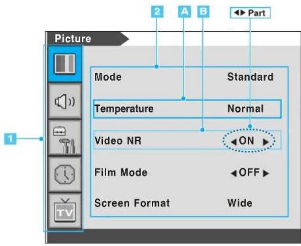
1 Main Menu
Press Menu/Set button on the remote control to enter the main OSD menu. First, select Main menu item you need with CH+/CH- key. To select a main menu items, just press VOL+ or Menu/Set button on the Remote Control.
2 Sub Menu
Each menu item has its own sub menu items to set.
3 Sub Menu items
A: If there is no ◀▶ part, the item has an sub menu.
You can enter the sub menu and adjust an item you need.
Select sub-menu item with CH+/CH- button on the remote control and press VOL+ or Menu/Set button to enter the submenu.
B : If there is a ◀▶ part, you can set the item by selecting ◀▶. Ex) ◀ON ▶ or ◀OFF ▶
Press VOL+ or Menu/Set button to set a ◀▶ part, and adjust it with CH+/CH- key.
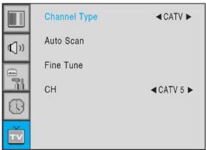
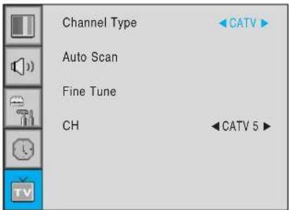
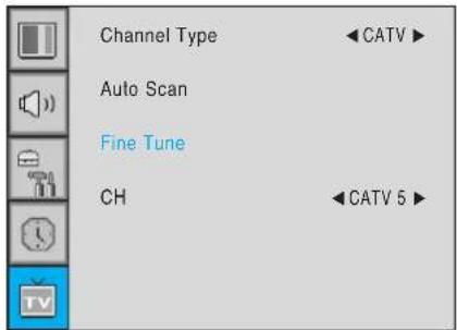
Channel Type
Before your television can begin memorizing the available channels, you must specify the type of signal source that is connected to the TV (i.e., an antenna, a standard cable system, an HRC, or an IRC).
1 Press Menu/set button to display the main OSD menu.
2 Select the TV main menu item.
3 Press Menu/Set to enter the sub menu.
4 Select Channel Type and press VOL+ button to enter the ◀▶ parts. Then the cursor moves into the ◀▶ parts.
5 Select the channel type with CH+/CH- button and press BACK button. You can select AIR, CATV (Cable TV), IRC or HRC.

- You can enter the TV menu in TV mode only. (When you watch a TV channel.)

Auto Scan
1 Press Menu/set button to display the main OSD menu.
2 Select the TV Main menu.
3 Press Menu/Set to enter the sub menu.
4 Select Auto Scan with CH+/CH- button and press Menu/Set button on the remote control. Then the tuning bar will appear and scanning will start.
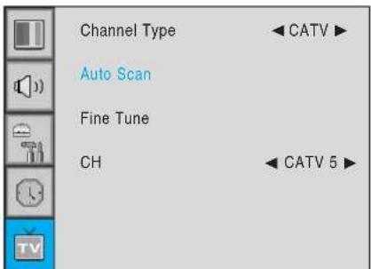

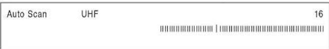

Notes
- Only scanned channels can be stored as Favorite channels.
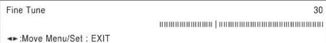
Fine Tune
The Fine Tuning function lets you manually adjust the Monitor's tuner if you have difficulty tuning analog Channels. Press Menu/set button to display the main OSD menu.
1 Press Menu/set button to display the main OSD menu.
2 Select the TV main menu item.
3 Press Menu/Set to enter the Fine tune sub menu.
4 Select Fine tune with CH+/CH- button and press Menu/Set button. Then you can see the adjust bar.
5 Adjust the fine tune with VOL+ or VOL- button.

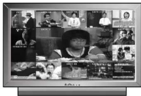
Digest
In the Digest function, you can watch 15 programs at the same time. (This function works only in TV mode)
1 Press the Digest button on the Remote Control.
2 By pressing the channel number, the selected channel becomes main window.
3 You can make off the Digest Function by pressing Digest button again.

a Set the favorite channel
You can store of your favorite channels for each available input source (such as TV or CATV).
Then, when you press the FAVORITE button on the remote control, the Monitor display only the favorite channels you previously stored, allowing you to quickly and easily find frequently wanted channels.
1 Press Menu/set button to display the main OSD menu.
2 Select the TV main menu.
3 Press Menu/Set to enter the TV sub menu.
4 Select CH and press the Menu/Set button.
Then the cursor moves into the ◀▶ parts and the Skip and Fav menu appear.
5 In the ◀▶ parts, select the channel to skip or set as the favorite channels.
6 Then press CH- button on the remote control to enter the sub menu.
7 In sub menu, move with CH- and CH+ button and set the values with VOL+ and VOL- button.
Sub menu appears
You can add or erase the current channel by the remote control.
① CH ADD
Add the current channel into the scanned channel list.
② CH ERASE
Remove the current channel from the scanned channel list.

Notes
- Only scanned channels can be set as Favorite Channels.
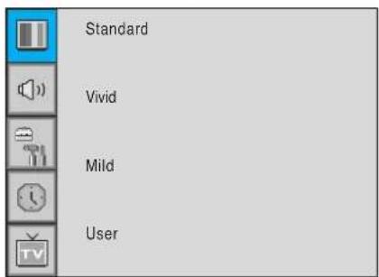
Mode
Your the Monitor has 3 automatic factory preset picture settings ("Standard", "Vivid" and "Mild"). You can choose Standard, Vivid or Mild by pressing "Picture" button on the remote control (or by making a selection from the menu). Or you can select USER which automatically recalls your personalized picture setting.
1 Press Menu/set button to display the main OSD menu.
2 Select the picture main menu.
3 Press Menu/Set to enter the sub menu.
4 Select Mode and press Menu/Set to enter the sub menu. Then the picture sub mode appear.
5 Select the picture mode and press Menu/Set button.
6 You will see the picture setting bars. Just Press BACK button on the remote control. You can adjust each values of the picture setting, but the changed values are stored as in USER mode.
USER mode has additional settings in a sub-menu: See next page.


Notes
- Alternative method : Just press the "Picture" button on the remote control. Each time it is pressed, different mode is selected.
Picture Mode is to set CH+ or adjust Picture Adjust, Mode, Video Noise Reduction, Screen Format and Burn Protection.
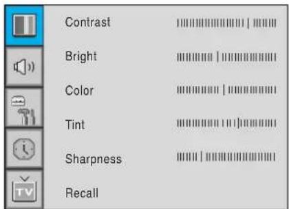
Adjust USER Mode
You can change the Contrast, Brightness, Color, and Sharpness according to personal preference in USER mode.
1 Select the item to adjust with CH-, CH+ button.
2 Press Menu/Set button.
3 Adjust the item with VOL-, VOL+ button.
4 To cancel all adjust, select Recall and press Menu/Set button.
For a more detailed description of these settings, see the next page.
Select USER mode (Previous page)

| Contrast | |
| Bright | |
| Color | |
| Tint | |
| Sharpness | |
| Recall |
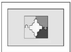
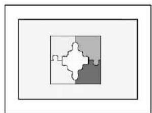
Contrast
Adjust brightness difference between bright part of the screen and dark part.
natural_image
Abstract geometric pattern with interlocking shapes in white and gray (no text or symbols)Distinct Vague
natural_image
Abstract geometric pattern with interlocking shapes in white, gray, and dark gray (no text or symbols)▶
Brightness
Adjust brightness of the screen.

natural_image
Solid gray rectangle with white border (no text or symbols)Dark Bright
natural_image
Simple gray rectangle with a thin border, no text or symbols present.▶
Color
Adjust deep and light color of the screen.

natural_image
Simple line drawing of a leafy branch (no text or symbols)Decrease Increase

natural_image
Illustration of a leafy branch with two leaves (no text or symbols)▶
Tint
Adjusts the balance between green and yellow.

natural_image
Silhouette of a plant with leaves and flowers (no text or symbols)Green color is deeper Red color is deeper

natural_image
Illustration of a leafy plant with two leaves (no text or symbols)Sharpness
Adjust vividness of the screen.

natural_image
Simple line drawing of two leafy branches (no text or symbols)Less sharp Sharp

natural_image
Black-and-white line drawing of a leafy branch with two leaves (no text or symbols)▶
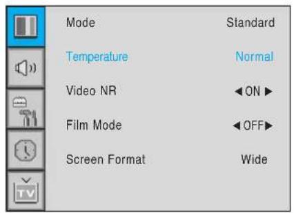
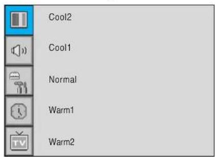
Temperature
Your the Monitor has 5 screen temperatures (color settings):
1 Press Menu/set button to display the main OSD menu.
2 Select the picture main menu.
3 Press Menu/Set to enter the picture menu.
4 Select Temperature and press Menu/Set to enter the sub menu. Then the Picture-Temperature sub menu appear.
5 Select the Temperature mode with CH-/CH+ button and press Menu/Set button.
6 Press BACK button to return.
Cool 1,2
Screen seems cool: Strong Blue
Normal
Normal: Factory default.
Warm 1, 2
Screen seems warm: Strong Red

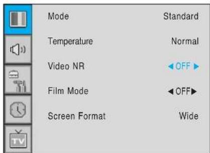
Video NR
This function automatically filters out and reduces the image noise and improves picture quality where receiving weak signals.
1 Press Menu/Set button to display the main OSD menu.
2 Select the picture main menu item.
3 Press Menu/Set to enter the sub menu.
4 Select Video NR and press VOL+ button to enter the ◀▶ parts. Then the cursor moves into the ◀▶ parts.
5 Turn on or off Video NR function with CH+/CH-button and press BACK button.

Screen Format
Your the Monitor has four Screen Formats: WIDE, PANORAMA, ZOOM1, ZOOM2, 4:3. (For more detail description for these modes, refer to the next page.)
1 Press Menu/Set button to display the main OSD menu.
2 Select the picture main menu.
3 Press Menu/Set to enter the picture menu.
4 Select Screen Format and press Menu/Set to enter the sub menu. Then the Screen Format sub menu appear.
5 Select the screen format you want and press Menu/Set button

Screen Format Description
Wide
Wide video: No change.
4:3 video: Expands 4:3 video signal horizontally to fit the Wide screen.
Panorama
Wide video: No change.
4:3 video: Expands 4:3 video horizontally to fit the Wide screen and to minimize distortion, sides are expanded more than center.
Zoom 1
Expands Wide mode screen vertically.
Zoom 2
Expands zoom 1 mode screen vertically.
4:3
Wide video: The image is suppressed.
4:3 video: No expansion. There are gray areas besides the image.

natural_image
Simple diagram with a large circle and two smaller circles inside a rectangle (no text or symbols)
natural_image
Simple diagram with three gray circles inside a rectangle (no text or symbols)
natural_image
Simple diagram with two gray circles inside a rectangle, no text or symbols present
natural_image
Simple diagram with two gray oval shapes inside a rectangle, no text or symbols present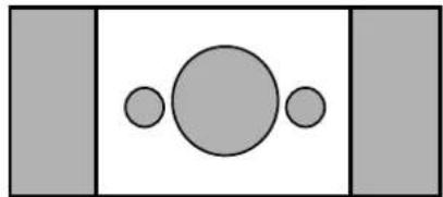
natural_image
Simple geometric diagram with three circles inside a rectangle, no text or symbols presentIn PC mode, you can adjust the H, V-Position, Native Mode and Phase. Also you can adjust them automatically.
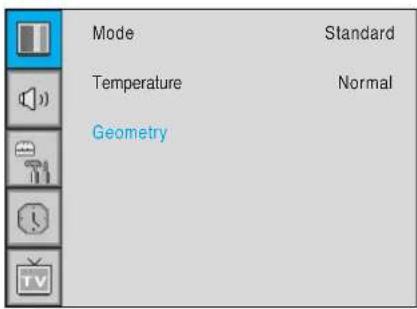
Geometry
You can change H, V-Position, Native Mode and Phase in PC mode like usual PC monitors.
You can also adjust them automatically. (Auto adjust function.)
1 Press Menu/set button to display the main OSD menu.
2 Select the picture main menu with CH+, CH- button.
3 Press Menu/Set to enter the sub menu.
4 Select Geometry and press Menu/Set to enter the sub menu. Then the picture Geometry sub menu will appear.
1 Select the item to adjust with CH-, CH+ button.
2 Press Menu/Set button.
3 Then the cursor moves on the bar and you can adjust the value with VOL-, VOL+ button.
4 To adjust these items, automatically, select Auto Adjust and press Menu/Set button.

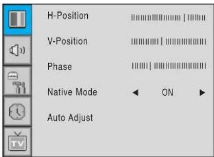
For more detail description refer to the next page.
\* \* \* \* \* \* \* \* \* \* \* \* \* \* \* \* \* \* \* \* \* \* \* \* \* \* \* \* \* \* \* \* \* \* \* \* \* \* \* \* \* \*
H-POSITION
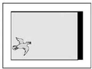
natural_image
Simple line drawing of a bird in flight against a plain background (no text or symbols)◀
natural_image
Simple line drawing of a bird flying near a flag (no text or symbols)▶
V-POSITION
natural_image
Simple line drawing of a flying bird in flight against a plain background (no text or symbols)◀
natural_image
Simple line drawing of a flying bird in flight against a plain background (no text or symbols)▶
PHASE
Mismatch
natural_image
Simple geometric diagram with two concentric rectangles (no text or symbols)Match
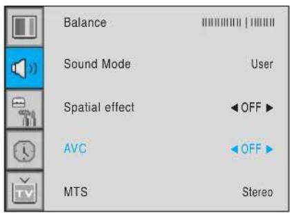
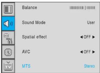
In SOUND Menu, you can adjust balance, MTS (Multi-Track Sound), AVC (Auto Volume Control) and select the equalizer settings.
Balance
This control allows you to adjust the balance of the left and right speaker output.
1 Press Menu/set button to display the main OSD menu.
2 Select the SOUND main menu.
3 Press Menu/Set to enter the sub menu.
4 Select Balance and press Menu/Set button.
5 Adjust the balance with VOL-, VOL+ button and press Menu/Set button.
Sound Mode
Your the Monitor has four automatic sound settings ("Standard", "Movie", "Music" and "News") that are preset at the factory. You can activate either Standard, Movie, Music or News by pressing "SOUND" on the remote control (or by making a selection from the menu) or you can select "Custom" which automatically recalls your personalized sound settings.
1 Press Menu/set button to display the main OSD menu.
2 Select the SOUND main menu.
3 Press Menu/Set button to enter the sub menu.
4 Select Sound Mode and press Menu/Set to enter the sub menu. Then the Mode sub menu appear.
5 Select the Equalizer setting and press Menu/Set button.
6 You will see the Equalizer bars. Just press BACK button on the remote control. You can adjust each values of Equalizer, but the changed values are stored as in USER mode.
USER mode require more settings. It has sub menu: See next page.

bar
Equalizer | Frequency | Value | | :--- | :--- | | 0.1 | 0.1 | | 0.5 | 0.5 | | 1.5 | 1.5 | | 5.0 | 5.0 | | 10.0kHz | 10.0 |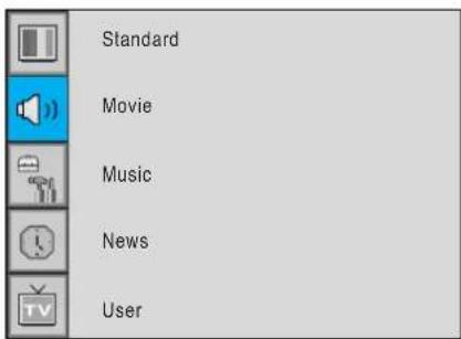
User Adjust
You can use the OSD menu to change the Treble, Bass, Balance and DRC according to your preference.
1 Equalizer menu appear when you select USER mode.
2 Select a gain bar with VOL+, VOL- button on the remote control and adjust it with CH+/CH- button.
3 Press BACK or BACK button on the remote control to exit Equalizer. The result will be saved automatically.
Select USER mode (Previous page)
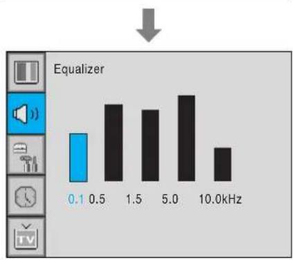
bar
Equalizer | Frequency (kHz) | Value | |---|---| | 0.1 | 1.0 | | 0.5 | 2.0 | | 1.5 | 1.8 | | 5.0 | 2.2 | | 10.0 | 1.3 |Spatial Effect
This function can create surround effect such as the sound seems to come from all directions.
1 Press Menu/set button to display the main OSD menu.
2 Select the SOUND main menu item with CH+/CH- button.
3 Press Menu/Set to enter the sub menu.
4 Select Spatial effect and press VOL+ button.
5 Turn on or off Spatial effect function with CH+/CH-button and press Menu/Set button.
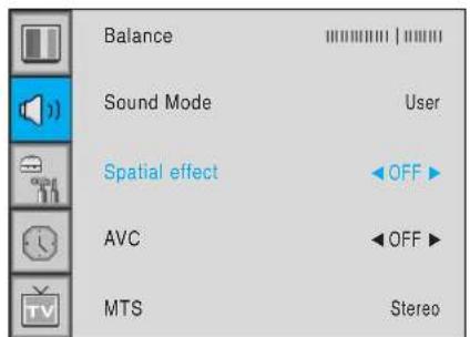
AVC(Auto Volume Control)
This function adjust sound volume level automatically depending on the source.
1 Press Menu/set button to display the main OSD menu.
2 Select the SOUND main menu.
3 Press Menu/Set to enter the sub menu.
4 Select AVC and press VOL+ button to enter the ◀▶ parts. Then the cursor moves into the ◀▶ parts.
5 Turn on or off AVC function with CH+/CH- button and press BACK button.
MTS (Multichannel Television Sound)
Select sound signal format from the input source. There are Mono, Stereo, SAP sound formats.
1 Press Menu/set button to display the main OSD menu.
2 Select the SOUND main menu with CH+/CH-button on the remote control.
3 Press Menu/Set to enter the sub menu.
4 Select MTS and press Menu/Set to enter the sub menu. Then the MTS sub menu appear.
5 Select the MTS format with CH+/CH- and press Menu/Set button.
The available sound formats are displayed. Usually, you can see Mono and Stereo.

Translucent
Adjust the transparency of the OSD menu. There are 8 step from OFF to 7.
1 Press Menu/set button to display the main OSD menu.
2 Select the SET UP main menu with CH+/CH-button on the remote control.
3 Press Menu/Set to enter the sub menu.
4 Select Translucent and press VOL+ button to enter the ◀► parts. Then the cursor moves into the ◀► parts.
5 Adjust with CH+/CH- button and press EXIT button.
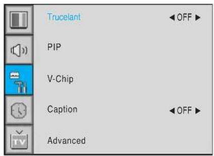
PIP (Picture In Picture)
You can watch two channels or sources at the same time. And set up PIP size and position.
1 Press Menu/set button to display the main OSD menu.
2 Select the SET UP main menu with CH+/CH- button on the remote control.
3 Press Menu/Set to enter the sub menu.
4 Select PIP and press Menu/Set to enter the sub menu. Then the PIP sub menu appear.
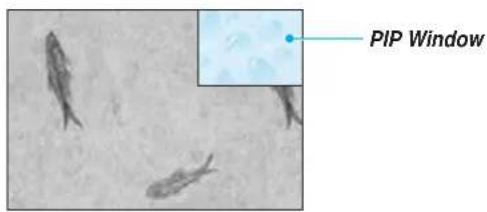

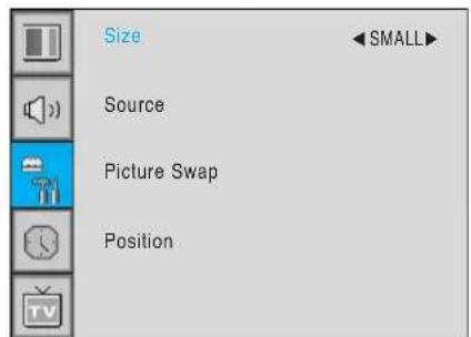
Size in PIP (Picture In Picture)
Change the size of the PIP window. There are 3 sizes: SMALL, Large, Twin.
1 Select Size and press VOL+ button to enter the ◀▶ parts. Then the cursor moves into the ◀▶ parts.
2 Adjust size function with CH+/CH- button and press Menu/Set button.
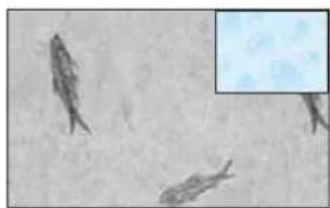
natural_image
Microscopic view of elongated biological structures with a magnified inset showing internal detail (no text or symbols)SMALL LARGE TWIN

natural_image
Microscopic view of biological cells with visible internal structures (no text or labels)
natural_image
Microscopic view of a single elongated biological structure on the left, and a magnified view of cellular or tissue samples on the right (no text or symbols)Source in PIP
Change the source of the PIP window.
1 Select Source and press Menu/Set to enter the sub menu. Then the PIP sub menu appear.
2 The available sources will be displayed. Select the source and press Menu/Set button.
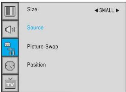
This picture is an example. The displayed sources may be different depending on the main input source.
| PIP\Main | TV AV 1 | AV 2 | S-Video/AV 3 | Component1 | Component2 PC | DVI | ||
| TV | √ | √ | √ | √ | √ | √ | √ | √ |
| AV 1 | √ | - | √ | √ | √ | √ | √ | √ |
| AV 2 | √ | √ | - | √ | √ | √ | √ | √ |
| S-Video/AV 3 | √ | √ | √ | - | √ | √ | √ | √ |
| Component1 | √ | √ | √ | √ | - | - | - | - |
| Component2 | √ | √ | √ | √ | - | - | - | - |
| PC | √ | √ | √ | √ | - | - | - | - |
| DVI | √ | √ | √ | √ | - | - | - | - |
Picture Swap in PIP (Picture In Picture)
Swap the sources of the main screen and the PIP window.
Select Picture Swap and press Menu/Set button.
Position in PIP
Change the position of the PIP window.
1 Select Position with CH+/CH- button on the remote control and press Menu/Set to enter the sub menu. Then the PIP sub menu appear.
2 In Sub Menu, there are four positions. Select the position with CH+/CH- button on the remote control and press BACK button.

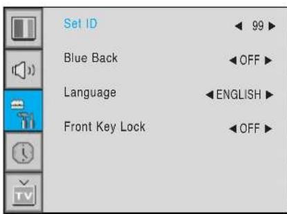
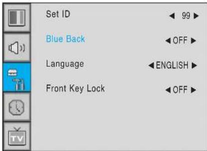
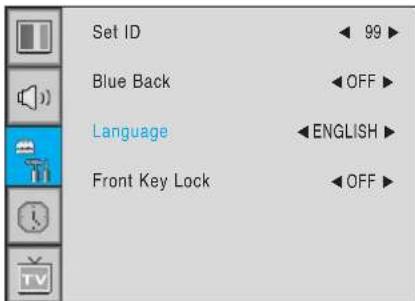
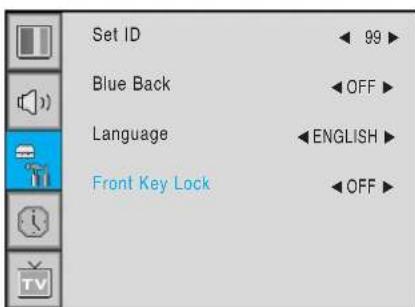
Advanced
You can se up ID, Blue Back, Language and Front Key Lock in Advanced Menu.
1 Press Menu/set button to display the main OSD menu.
2 Select the SET UP main menu with CH+ / CH-button on the remote control.
3 Press Menu/Set to enter the sub menu.
4 Select Advanced and press Menu/Set to enter the Advanced menu.
Then the Advanced sub menu appear.

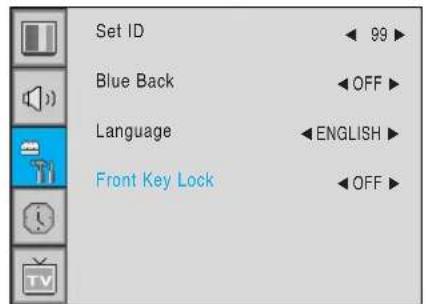
Set ID in Advanced
Set the ID of the Monitor for mass-controlling through the serial port.
1 Select Set ID and press VOL+ button to enter the ◀▶ part. Then the cursor moves into the ◀▶ part.
2 Adjust with CH+ / CH- button and press BACK button.
Blue Back in Advanced
You can set to display blue-color screen instead of noise screen.
1 Select Blue Back and press VOL+ button to enter the ◀▶ parts. Then the cursor moves into the ◀▶ parts.
2 Turn the function on or off with CH+/CH- button and press BACK button.
Language in Advanced
Set the language to use in OSD.
Supported languages are English, French, German, Spanish, Italian.
1 Select Language and press VOL+ button to enter the ◀▶ parts. Then the cursor moves into the ◀▶ parts.
2 Choose the Language with CH+ / CH- button and press BACK button.
Front Key Lock in Advanced
Lock the OSD panel of the Monitor. It can protect the Monitor from children's power on/off or other operation by miss.
1 Select Front Key Lock and press VOL+ button to enter the ◀▶ parts. Then the cursor moves into the ◀▶ parts.
2 Turn the function on or off with CH+/CH- button and press BACK button.
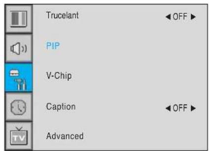
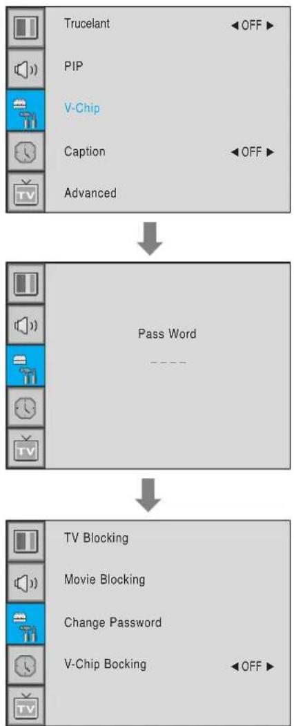
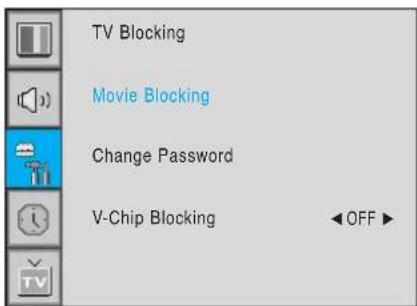
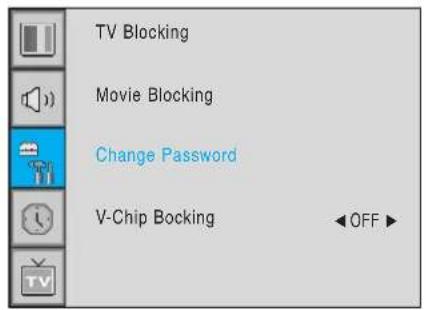
V-Chip (TV Parental Guidelines
Parental restrictions can be set up using either of two methods: The TV guidelines or the MPAA rating.
1 Press Menu/set button to display the main OSD menu.
2 Select the SET UP main menu with CH+/CH-button on the remote control.
3 Press Menu/Set to enter the sub menu.
4 After enter the password, the V-Chip sub menu appear.
flowchart
graph TD
    A["Trucelant"] --> B["OFF"]
    C["PIP"] --> D["Pass Word"]
    E["V-Chip"] --> F["Pass Word"]
    G["Caption"] --> H["Pass Word"]
    I["Advanced"] --> J["Pass Word"]
    K["TV Blocking"] --> L["Movie Blocking"]
    M["Change Password"] --> N["V-Chip Blocking"]
    O["OFF"] --> P["OFF"]

Caution
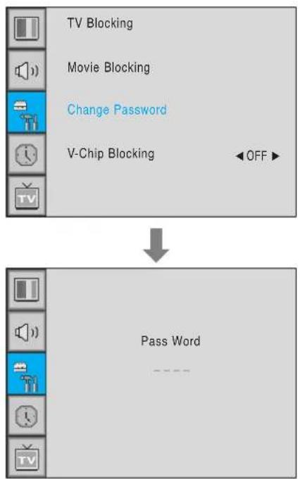
• The factory default number is 0000 and the master button number is 9673.
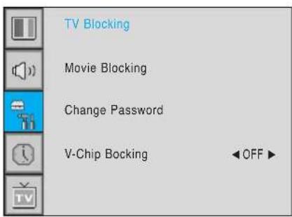
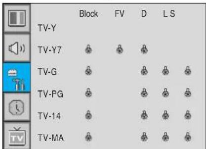
TV Blocking in V-Chip
You can set up Restrictions Using the "TV Parental Guidelines" of FCC.
1 Select TV Blocking with CH+/CH- button on the remote control and press Menu/Set to enter the sub menu. Then the TV Blocking sub menu appear.
2 You can independently lock the TV ratings. The locked TV (FCC) ratings are indicated by the symbol 🔒.
3 Press CH+/CH-/VOL+/VOL- buttons and the Menu/Set button to activate the appropriate restrictions for TV (FCC) rating system.
Note: These categories consist of two separate groups: TV-Y and TV-Y7 (young children through age 7), and TV-G through TV-MA (everybody else).
The restrictions for these two groups work independently: If a household includes very young children as well as young adults, the TV guidelines must be set up separately for each age group.

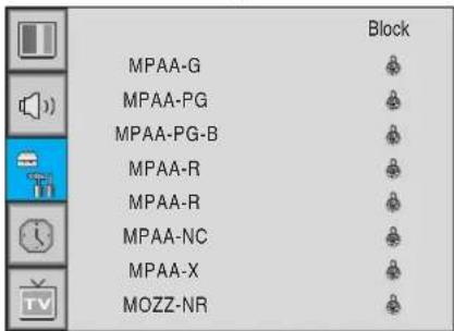
Movie Blocking in V-Chip
The Movie Blocking uses the Motion Picture Association of America (MPAA) system, and its main application is for movies. When the Rating Controls is on, the TV will automatically block any programs that are coded with objectionable ratings (either MPAA or TV-Ratings).
1 Select Movie Blocking with CH+/CH- button on the remote control and press Menu/Set to enter the sub menu. Then the Movie Blocking sub menu appear.
2 You can independently lock the TV ratings. The locked Movie (FCC) ratings are indicated by the symbol 🔒.
3 Press CH+/CH- buttons and the Menu/Set button to activate the appropriate restrictions for MPAA rating system.

Change Password in V-Chip
1 Select Change Password with CH+/CH- button on the remote control and press Menu/Set to enter the sub menu. Then the Pass Word change sub menu appear.
2 Enter the new password with numeric buttons on the remote control.
V-Chip Blocking in V-Chip
1 Select V-Chip Blocking with CH+/CH- buttons on the remote control.
2 Enter to the ◀▶ part by pressing VOL+ button. Then the cursor moves into the ◀▶ parts.
3 ON / OFF the V-Chip Blocking with CH+/CH- buttons.
4 Exit with Back button on the remote control.
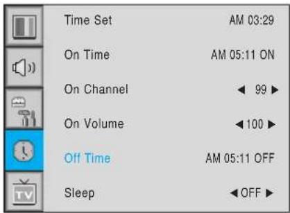
In the TIME menu, you can set the current time and auto power on / off.
Time Set
Set the current time.
1 Press Menu/set button to display the main OSD menu.
2 Select the TIME main menu.
3 Press Menu/Set to enter the sub menu.
4 Select Time Set by pressing VOL+ button.
5 Move the cursor by pressing VOL-, VOL+ button and adjust time by CH+, CH- button.
| Time Set | AM 03:29 |
| On Time | AM 05:11 ON |
| On Channel | ← 99 ▶ |
| On Volume | ←100 ▶ |
| Off Time | AM 05:11 OFF |
| Sleep | ←OFF ▶ |
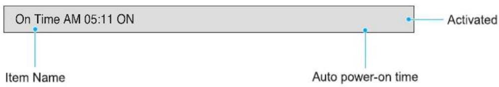
On Time
This the Monitor can be set to turn on automatically at specific time that you choose. Before using the timer, you must set the Monitor's Time as described previously.
1 Press Menu/set button to display the main OSD menu.
2 Select the TIME main menu with CH+/CH- button on the remote control.
3 Press Menu/Set to enter the sub menu.
4 Select On Time with CH+/CH- button and press VOL+ button.
5 Move the cursor by VOL-, VOL+ button and adjust time by CH+, CH- button.
| Time Set | AM 03:29 |
| On Time | AM 05:11 ON |
| On Channel | ← 99 ▶ |
| On Volume | ← 100 ▶ |
| Off Time | AM 05:11 OFF |
| Sleep | ← OFF ▶ |
On Channel
Set the channel when the Monitor power turn on automatically.
• Available only when the Time is set and On Time is ON.
1 Press Menu/set button to display the main OSD menu.
2 Select the TIME main menu with CH+/CH- button on the remote control.
3 Press Menu/Set to enter the sub menu.
4 Select On Channel.
5 Enter to the ◀▶ part with VOL+ button. Then the cursor moves into the ◀▶ parts.
6 Adjust the channel with CH+/CH- button. Press BACK button to return.
| Time Set | AM 03:29 |
| On Time | AM 05:11 ON |
| On Channel | ← 99 ▶ |
| On Volume | ← 100 ▶ |
| Off Time | AM 05:11 OFF |
| Sleep | ←OFF ▶ |
On Volume
• Available only when the Time is set and On Time is ON.
1 Press Menu/set button to display the main OSD menu.
2 Select the TIME main menu with CH+/CH- button on the remote control.
3 Press Menu/Set to enter the sub menu.
4 Select On Volume.
5 Enter to the ◀▶ part by pressing VOL+ button. Then the cursor moves into the ◀▶ parts.
6 Adjust the sound volume level with CH+/CH- button.
| Time Set | AM 03:29 |
| On Time | AM 05:11 ON |
| On Channel | ← 99 ▶ |
| On Volume | ←100 ▶ |
| Off Time | AM 05:11 OFF |
| Sleep | ←OFF ▶ |
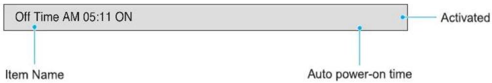
Off Time
This the Monitor can be set to turn off automatically at specific times that you choose. Before using the timer, you must set the Monitor's clock as described previously.
1 Press Menu/set button to display the main OSD menu.
2 Select the TIME main menu with CH+/CH- button on the remote control.
3 Press Menu/Set to enter the sub menu.
4 Select Off Time with CH+/CH- button on the remote control and press VOL+ button.
5 Move the cursor with VOL-/VOL+ button and adjust time with CH+/CH- button.
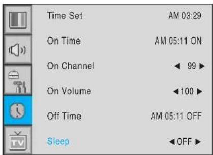
Sleep
You can set your the Monitor to automatically turn off after a preset interval. If you turn off the Monitor in the state of setting up sleep time and turn on again, sleep time erased therefore set up again. The time period runs from OFF(0min) to 180min. (OFF, 10min, 20, 30, 60, 90, 120, 150, 180)
1 Press Menu/set button to display the main OSD menu.
2 Select the TIME main menu. with CH+/CH- button on the remote control.
3 Press Menu/Set to enter the sub menu.
4 Select Sleep with CH+/CH- button on the remote control and press VOL+ button.
5 Enter to the ◀▶ part with VOL+ button. Then the cursor moves into the ◀▶ parts.
6 Set the time period with CH+/CH- button.
7 Press BACK button to return.
If your monitor is not working properly, please scan this list of problems and possible solutions. It may save you time and money.
| Quick Action for Possible SolutionProblem | |
| No picture & No sound | Check whether the Monitor is turned on.Power cord inserted into wall outlet?Plug another product's power cord into the wall outlet where the Monitor's power cord was plugged in. |
| Picture OK & No sound | Press the VOLUME(▶) button.Check the audio input signal. |
| The remote control doesn't work | Check to see if there is any object between the Monitor and the remote control causing obstruction.Check to see if the batteries are installed with the correct polarities. |
| Digital broadcasting screen problem | Check the digital signal strength and input antenna. |
| No or Poor color or Poor picture | Select Color in the Picture and press VOLUME (▶) button.Keep a certain distance between the Monitor and the input source.Activate any function to restore the brightness of the picture.Check to see that both the monitor and the source are plugged in and turned on. |
| The image is too light or too dark | Adjust the Brightness or Contrast settings. |
| The image is too large or too small | Adjust the Size settings. |
| No output from one of the speakers | Adjust Balance in the Sound Menu. |
Limited Warranty
Subject to the Limitations, Exclusions and Disclaimers hereof, InFocus Corporation ("InFocus") warrants that the LCD Thin Display Device and Accessories (hereinafter collectively or individually referred to as "Product" as appropriate) purchased from InFocus, an InFocus dis tributor, or an InFocus reseller will conform to InFocus' specifications and be free from defects in material or workmanship for the respective Limited Warranty period provided below. InFocus does not warrant that the Product will meet the specific requirements of the end-user customer. If the Product while subject to this Limited Warranty, is defective in material or workmanship during the warranty period, then InFocus, at its option, will REPAIR or REPLACE the Product. All exchanged parts and Products replaced under this Limited Warranty will become property of InFocus. InFocus' sole obligation is to supply (or pay for) all labor necessary to repair the Product found to be defective within the Limited Warranty period and to repair or replace defective parts with new parts or, at the option of InFocus, serviceable used parts that are equivalent or superior to new parts performance. Limited Warranty periods are as follows:
- Product Limited Warranty Period: one (1) year from date of purchase.
- Accessory Product Limited Warranty Period: one (1) year from date of purchase.
WARRANTY LIMITATION AND EXCLUSION
THIS WARRANTY SETS FORTH INFOCUS' MAXIMUM LIABILITY FOR ITS PRODUCT. THIS WARRANTY EXTENDS ONLY TO PRODUCTS PURCHASED FROM INFOCUS OR AN INFOCUS AUTHORIZED RESELLER. . InFocus shall have no further obligation under the foregoing Limited Warranty if the Product has been damaged due to abuse, improper ventilation, fire, water, disaster, mispackaging, shipping, lightning or other acts of nature, misuse, neglect, smoke exposure (cigarette or otherwise), accident, unusual physical or electrical stress and/or power surges, unauthorized modifications (including use of an unauthorized mount), tampering, alterations, service other than by InFocus or its authorized service providers, or failure caused other than from ordinary use or failure to properly use the Product in the application for which said Product was intended. In addition, failure of the end-user to follow maintenance procedures as outlined in the product's user guide, where a schedule is specified for regular cleaning of certain parts (based on usage and environment), and the end-user has failed to follow such schedule, the Product will not be covered under the Limited Warranty. Finally, InFocus shall have no further obligation if InFocus Product was subjected to operating conditions outside of the range specified in the user's guide or in this Limited Warranty. This Limited Warranty excludes Product cleaning, repair, or replacement of plastics and glass due to cosmetic damage and damage as a result of normal wear. Product repair outside of the terms of the Limited Warranty will be on a time and materials basis. Prolonged Product "demonstration" causes unusual Product wear and is not considered normal use under the terms of this Limited Warranty. Wide screen format displays (16:9, the aspect ratio of the screen width to height) are primarily designed to view wide screen format full-motion video. The images displayed on them should primarily be in the wide screen 16:9 ratio format, or expanded to fill the screen if your model offers this feature, and constantly moving. Displaying stationary graphics and images on screen, such as the dark side-bars on non-expanded standard 4:3 ratio format video, should be limited to no more than 15% of the total viewing time. LCD burn-in as a result of excessive display of static images is not covered under the terms of this Limited Warranty. The Accessory Product Limited Warranty covers the accessory item only and excludes normal wear. Remanufactured Products and Software Products are exempt from the foregoing Limited Warranty. Please refer to the appropriate Remanufactured Product Limited Warranty or Software Product Limited Warranty for applicable Warranty information.
DISCLAIMER OF UNSTATED WARRANTIES
THE WARRANTY PRINTED ABOVE IS THE ONLY WARRANTY APPLICABLE TO THIS PRODUCT. ALL OTHER WARRANTIES, EXPRESS OR IMPLIED, INCLUDING, BUT NOT LIMITED TO, THE IMPLIED WARRANTIES OF MERCHANTABILITY AND FITNESS FOR PARTICULAR PURPOSE ARE DISCLAIMED. THERE ARE NO WARRANTIES THAT EXTEND BEYOND THE DESCRIPTION ON THE FACE HEREOF AND THE FOREGOING WARRANTY SHALL NOT BE EXTENDED, ALTERED OR VARIED EXCEPT BY WRITTEN INSTRUMENT SIGNED BY INFOCUS. SOME JURISDICTIONS DO NOT ALLOW LIMITATIONS ON HOW LONG AN IMPLIED WARRANTY MAY LAST, SO SUCH LIMITATIONS MAY NOT APPLY TO YOU.
Limited Warranty Period
The Limited Warranty periods hereof commence on the date of purchase by the end-user customer. These Limited Warranty provisions shall apply only to the end-user purchaser (first person or entity that purchased a new Product for personal or business use and not for the purpose of distribution or resale). SOME JURISDICTIONS MAY GRANT YOU CONSUMER RIGHTS WITH MINIMUM WARRANTY DURATION THAT DIFFER FROM THE DURATIONS PROVIDED HEREIN, AND INFOCUS WILL HONOR ALL SUCH CONSUMER RIGHTS.
To Be Eligible For Limited Warranty Coverage
Any person exercising a claim under this Limited Warranty must establish to the satisfaction of InFocus both the date of purchase and that the Product was purchased new from InFocus or an InFocus authorized reseller. The sales receipt or invoice, showing the date of purchase of the Product is the proof of the date of purchase.
To Obtain Warranty Service
During the Limited Warranty period, to exercise this Limited Warranty, the purchaser must first contact 1) InFocus, 2) a service facility authorized by InFocus or 3) the place of original purchase.
InFocus Customer Service - 1-503-685-8888 or visit www.infocus.com/service
For Warranty service, the purchaser will be advised to return or deliver the defective Product freight and all fees prepaid, to an InFocus Service Center or to a service facility authorized by InFocus. When returning Product to InFocus, a Return Materials Authorization (RMA) # is required and must be clearly displayed on the outside of the shipping carton or a similar package affording an equal degree of protection. InFocus or the service facility authorized by InFocus will return the repaired/replaced Product freight prepaid to the purchaser.
Products returned for Warranty service must be accompanied by a written letter that: (i) explains the problem; (ii) provides proof of date of purchase; (iii) provides the authorized reseller's name; and (iv) provides the model and serial number of the Product. Upon request of InFocus Corporation or a service facility authorized by InFocus, proof of legal import must accompany the warranty repair Product, otherwise the Product must be returned to the place of original purchase, to the manufacturer (Purchaser must bear all tax, duty and freight), or the Purchaser must bear charges for the warranty repair.
No repair or replacement of Product or part thereof shall extend the Limited Warranty period as to the entire Product. Warranty on the repair part and workmanship shall only be effective for a period of ninety (90) days following the repair or replacement of that part or the remaining period of the Product Limited Warranty whichever is greater.
LIMITATION OF LIABILITY
IT IS UNDERSTOOD AND AGREED THAT INFOCUS' LIABILITY WHETHER IN CONTRACT, IN TORT, UNDER ANY WARRANTY, IN NEGLIGENCE OR OTHERWISE SHALL NOT EXCEED THE RETURN OF THE AMOUNT OF THE PURCHASE PRICE PAID BY PURCHASER AND UNDER NO CIRCUMSTANCES SHALL INFOCUS BE LIABLE FOR SPECIAL, INDIRECT, INCIDENTAL OR CONSEQUENTIAL DAMAGES OR LOST PROFITS, LOST REVENUES OR LOST SAVINGS. THE PRICE STATED FOR THE PRODUCTS IS A CONSIDERATION IN LIMITING INFOCUS' LIABILITY.
Limitation on Bringing Action - No action, regardless of form, arising out of the agreement to purchase the Product may be brought by purchaser more than one year after the cause of action has accrued.
Governing Law - Any action, regardless of form, arising out of the agreement to purchase the Product is governed by Oregon law.
Mandatory Arbitration - Any action, regardless of form, arising out of the agreement to purchase the Product is subject to mandatory arbitration.
SOME JURISDICTIONS DO NOT ALLOW THE EXCLUSION OR LIMITATION OF INCIDENTAL OR CONSEQUENTIAL DAMAGES SO THE ABOVE LIMITATION OR EXCLUSION MAY NOT APPLY TO YOU. THIS LIMITED WARRANTY GIVES YOU SPECIFIC LEGAL RIGHTS, AND YOU MAY ALSO HAVE OTHER RIGHTS, DEPENDING ON JURISDICTION.
- Foreword
- Overviewing your the Monitor
- Installation
- Connecting the Cable/Devices
- Setting the Channel
- Setting the Picture
- Setting the Sound
- Setting the Others
- Setting the Time
- Troubleshooting 50
- Warranty Card 51
- CAUTION
- WARNING
- FCC NOTICE
- Do not attempt to service the Monitor yourself. Refer all servicing to qualified service personnel. Unplug the unit from the wall outlet and refer servicing to qualified service personnel under the following conditions:
- OSD Key Position
- OSD key & Function
- OSD Key Function
- INPUT SELECT
- VOL/CH▲/▼
- Power On /Off
- Accessories
- RS-232C Configurations
- PIP (Picture In Picture) Keys
- MODE (On / Off)
- SOURCE
- SWAP
- MOVE
- MTS
- CH INFO
- PICTURE
- STILL
- SOUND
- SLEEP
- TIME
- Digest
- CH ADD
- CH ERASE
- CLOSE CAPTION
- V-CHIP
- Loading the Batteries
- Speaker Installation (Optional)
- Speaker Accessories
- Connecting the TV Cable
- Connecting the VCR
- With S-Video
- With AV input
- Watching VCR
- Notes
- Connecting the DVD
- How to use
- Component Input ports
- How to connect
- With Component
- With RGB(D-Sub) or DVI
- Notice
- Connecting a PC to the Monitor
- Pin Configuration
- To watch the PC screen
- Turning the Monitor On /Off
- Select Source
- Source Change
- TV Channel Selection
- Volume Control
- EXAMPLE of OSD Menu
- Main Menu
- Sub Menu
- Sub Menu items
- Channel Type
- Auto Scan
- Fine Tune
- Digest
- a Set the favorite channel
- Mode
- Adjust USER Mode
- Contrast
- Brightness
- Color
- Tint
- Sharpness
- Temperature
- Video NR
- Screen Format
- Screen Format Description
- Wide
- Panorama
- Zoom 1
- Zoom 2
- 4:3
- Geometry
- \* \* \* \* \* \* \* \* \* \* \* \* \* \* \* \* \* \* \* \* \* \* \* \* \* \* \* \* \* \* \* \* \* \* \* \* \* \* \* \* \* \*
- Balance
- Sound Mode
- User Adjust
- Spatial Effect
- AVC(Auto Volume Control)
- MTS (Multichannel Television Sound)
- Translucent
- PIP (Picture In Picture)
- Size in PIP (Picture In Picture)
- Source in PIP
- Picture Swap in PIP (Picture In Picture)
- Position in PIP
- Advanced
- Set ID in Advanced
- Blue Back in Advanced
- Language in Advanced
- Front Key Lock in Advanced
- V-Chip (TV Parental Guidelines
- TV Blocking in V-Chip
- Movie Blocking in V-Chip
- Change Password in V-Chip
- V-Chip Blocking in V-Chip
- Time Set
- On Time
- On Channel
- On Volume
- Off Time
- Sleep
- Limited Warranty
- WARRANTY LIMITATION AND EXCLUSION
- DISCLAIMER OF UNSTATED WARRANTIES
- Limited Warranty Period
- To Be Eligible For Limited Warranty Coverage
- To Obtain Warranty Service
- LIMITATION OF LIABILITY
Brand : INFOCUS
Model : TD40 NTSC
Category : Monitor