
DT-N24F - Pregnant JVC - Free user manual and instructions
Find the device manual for free DT-N24F JVC in PDF.

| Product Type | Portable Bluetooth Speaker |
| Model | DT-N24F |
| Brand | JVC |
| Dimensions (W x H x D) | 20 x 10 x 10 cm |
| Weight | 0.5 kg |
| Power Output | 10 W |
| Battery Capacity | 2000 mAh (Rechargeable Li-ion) |
| Battery Life | Up to 6 hours |
| Wireless Connectivity | Bluetooth 5.0 |
| Audio Input | 3.5 mm Aux-in |
| Charging Port | Micro USB |
| Controls | Power, Volume +/- , Play/Pause, Next/Previous track |
| Hands-free Function | Built-in microphone for calls |
| Water Resistance | IPX5 (splash proof) |
| Operating Range | Up to 10 meters |
| Materials | Plastic housing with fabric grille |
| Maintenance & Cleaning | Wipe with a soft, dry cloth. Do not use harsh chemicals. |
| Safety Precautions | Do not expose to extreme temperatures or moisture. Use only supplied charger. |
| Spare Parts & Repairability | Not user-serviceable. Contact JVC support for repairs. |
| General Information | Portable speaker for indoor and outdoor use. Compatible with most Bluetooth devices. |
Frequently Asked Questions - DT-N24F JVC
User questions about DT-N24F JVC
0 question about this device. Answer the ones you know or ask your own.
Ask a new question about this device
Download the instructions for your Pregnant in PDF format for free! Find your manual DT-N24F - JVC and take your electronic device back in hand. On this page are published all the documents necessary for the use of your device. DT-N24F by JVC.
USER MANUAL DT-N24F JVC
MULTI FORMAT LCD MONITOR
DT-N24F
INSTRUCTIONS
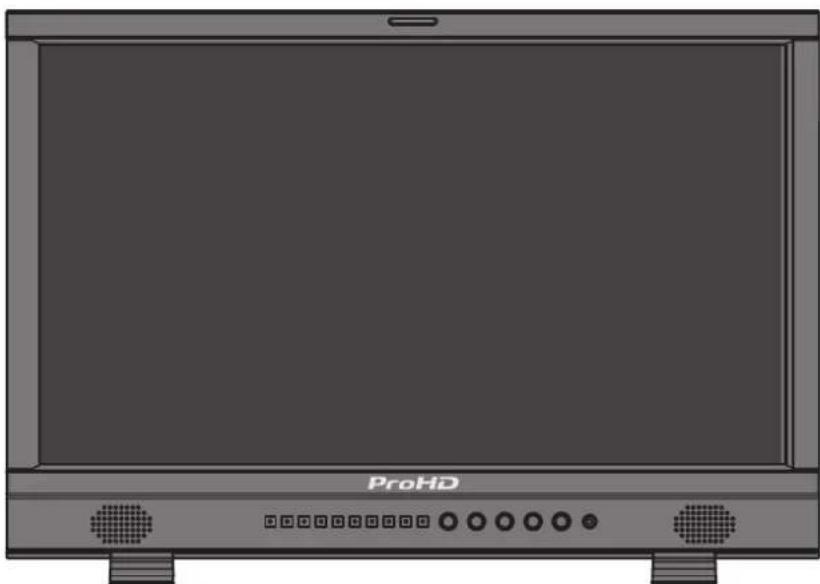
natural_image
Front view of a ProHD monitor with indicator lights and ports (no text or symbols on the screen)
CAUTION
RISK OF ELECTRICAL SHOCK DO NOT OPEN

CAUTION: To reduce the risk of electric shock. Do not remove cover (or back). No user serviceable parts inside. Refer servicing to qualified service personnel.

The lightning flash with arrowhead symbol, within an equilateral triangle is intended to alert the user to the presence of uninsulated “dangerous voltage” within the product’s enclosure that may be of sufficient magnitude to constitute a risk of electric shock to persons.

The exclamation point within an equilateral triangle is intended to alert the user to the presence of important operating and maintenance (servicing) instructions in the literature accompanying the appliance.
WARNING: TO REDUCE RISK OF FIRE OR ELECTRIC SHOCK, DO NOT EXPOSE THIS APPARATUS TO RAIN OR MOISTURE. NO OBJECTS FILLED WITH LIQUIDS, SUCH AS VASES, SHALL BE PLACED ON THE APPARATUS.
IMPORTANT SAFEGUARDS
Electrical energy can perform many useful functions. This unit has been engineered and manufactured to assure your personal safety. But IMPROPER USE CAN RESULT IN POTENTIAL ELECTRIC SHOCK OR FIRE. In order not to defeat the safeguards incorporated into this product, observe the following basic rules for its installation, use, and service. Please read these "IMPORTANT SAFEGUARDS" carefully before use.
- All the safety and operating instructions should be read before the product is operated.
- The safety and operating instructions should be retained for future reference.
- All warnings on the product and in the operating instructions should be adhered to.
- All operating instructions should be followed.
POWER CONNECTION
The power supply voltage rating of this product is AC 120 V(For U.S.A. and Canada) and AC 220 -240 V(For Europe and Asia).
The power cord attached conforms to the following power supply voltage and countries. Use only the power cord designated to ensure safety and EMC regulations of each country.
Not all types of power cords are supplied to this product.
For U.S.A. and Canada: AC 120V For Europe and Asia: AC 220-240V


This plug will fit only into a grounded power outlet. If you are unable to insert the plug into the outlet, contact your electrician to install the proper outlet. Do not defeat the safety purpose of the grounded plug.
This product should be operated only with the type of power source indicated on the label. If you are not sure of the type of power supply of your home, consult your product dealer or local electric power company.
Warning: This is a class A product. In a domestic environment this product may cause radio interference in which case the user may be required to take adequate measures.
- Before connecting other products such as VCR's and personal computers, you should turn off the power of this product for protection against electric shock.
- Do not use attachments not recommended by the manufacturer as they may be hazardous.
- When replacement parts are required, be sure the service technician has used replacement parts specified by the manufacturer or equivalents. Unauthorized substitutions may result in fire, electric shock, or other hazards.
-
Upon completion of any service or repairs to this product, ask the service technician to perform safety checks to determine that the product is in proper operating condition.
-
Do not install this product in the following places:
- in a damp or dusty room
- where the product is exposed to soot or steam, such as near the cooking counter or a humidifier
- near heat sources
- where condensation easily occurs, such as near the window
- in a location exposed to direct sunlight or strong light
- Do not place this product on an unstable cart, stand, or table. The product may fall, causing serious injury to a child or adult, and serious damage to the product.
The product should be mounted according to the manufacturer's instructions, and should use a mount recommended by the manufacturer. - Do not use this product near water.
- Be sure to install the product in the place where proper temperature and humidity are kept (☐ "Operating conditions" on page 19).
This product becomes hot during its use. Take enough care when handling the product.
Under the following conditions,
- Turn off the power.
- Unplug this product from the wall outlet.
- Refer service to qualified service personnel.
a) When the product emits smoke or unusual smell.
b) When the product exhibits a distinct change in performance —for example, no picture or no sound.
c) If liquid has been spilled, or objects have fallen on the product.
d) If the product has been exposed to rain or water.
e) If the product has been dropped or damaged in any way.
f) When the power supply cord or plug is damaged.
Safety Precautions (cont.)
Do not attempt to service this product yourself, as opening or removing covers may expose you to dangerous voltages and other hazards. Refer all service to qualified service personnel.
Do not use the product for a long time if the sound is distorted.
- When the product is left unattended and unused for a long period of time, unplug it from the wall outlet and disconnect the cable system.
- Do not overload wall outlets, extension cords, or convenience receptacles on other equipment as this can result in a risk of fire or electric shock.
Use only the power source specified on the unit.
• AC power: 120 V/220 - 240V, 50 Hz/60 Hz
- DC power: 11V-17V
- Slots and openings in the cabinet are provided for ventilation. These ensure reliable operation of the product and protect it from overheating. These openings must not be blocked or covered.
- Never push objects of any kind into this product through openings as they may touch dangerous voltage points or short-circuit the parts, which could result in a fire or electric shock.
- Never spill liquid of any kind on the product.
- Never place anything on the product. (Placing liquids, naked flames, cloths, paper, etc. on the product may cause a fire.)
- Do not apply any strong shock to the LCD panel. (Do not hit any object against it or push it with a sharp-pointed tool.)
- Do not put heavy objects on the product.
- Do not step on or hang on the product.
IMPORTANT SAFETY INSTRUCTIONS
1) Read these instructions.
2) Keep these instructions.
3) Heed all warnings.
4) Follow all instructions.
5) Do not use this apparatus near water.
6) Clean only with dry cloth.
7) Do not block any ventilation openings. Install in accordance with the manufacturer's instructions.
8) Do not install near any heat sources such as radiators, heat registers, stoves, or other apparatus (including amplifiers) that produce heat.
9) Do not defeat the safety purpose of the polarized or grounding-type plug. A polarized plug has two blades with one wider than the other. A grounding type plug has two blades and a third grounding prong. The wide blade or the third prong are provided for your safety. If the provided plug does not fit into your outlet, consult an electrician for replacement of the obsolete outlet.
10) Protect the power cord from being walked on or pinched particularly at plugs, convenience receptacles, and the point where they exit from the apparatus.
11) Only use attachments/accessories specified by the manufacturer.
12) Use only with the cart, stand, tripod, bracket, or table specified by the manufacturer, or sold with the apparatus. When a cart is used, use caution when moving the cart/apparatus combination to avoid injury from tip-over.
13) Unplug this apparatus during lightning storms or when unused for long periods of time.
14) Refer all servicing to qualified service personnel. Servicing is required when the apparatus has been damaged in any way, such as power-supply cord or plug is damaged, liquid has been spilled or objects have fallen into the apparatus, the apparatus has been exposed to rain or moisture, does not operate normally, or has been dropped.
15) Apparatus shall not be exposed to dripping or splashing and no objects filled with liquids, such as vases, shall be placed on the apparatus.
16) Batteries shall not be exposed to excessive heat such as sunshine, fire or the like.
17) When discarding batteries, environmental problems must be considered and the local rules or laws governing the disposal of these batteries must be followed strictly.

Operating Precautions
The LCD panel and backlight have life expectancy. Due to the basic characteristics of the LCD panel, an afterimage or uneven display may occur. It is recommended that you change images occasionally, activate the power saving function, or often turn off the power to reduce the load on the LCD panel. Continuous operations of the LCD panel may accelerate the deterioration.
Maintenance
Unplug this product from the wall outlet before cleaning.
LCD panel
To avoid irreparable change in appearance of the screen such as uneven color, discoloration, scratches, be careful about the following:
- Do not paste or stick anything using any glues or adhesive tapes.
- Do not write anything on the screen.
- Do not strike the screen with a hard object.
- Avoid condensation on the screen.
- Do not wipe the screen with any liquid such as water. In addition, wiping the screen with water-diluted neutral detergent or solvent such as alcohol, thinner, or benzine may affect the anti-reflection treatment of the screen.
- Do not wipe the screen forcefully.
Wipe stains off the LCD panel with a soft cloth. If the screen gets heavily stained, wipe it with a soft cloth soaked in water-diluted neutral detergent and wrung well, then wipe with a soft dry cloth.
Cabinet
To avoid the deterioration or damages of the cabinet such as its paint's peeling away, be careful about the following:
- Do not wipe the cabinet using solvent such as alcohol, thinner, or benzine.
- Do not expose the cabinet to any volatile substance such as insecticides.
- Do not allow any rubber or plastic in contact for a long time.
- Do not wipe the cabinet forcefully.
Wipe stains off the cabinet with a soft cloth. If the cabinet gets heavily stained, wipe it with a soft cloth soaked in water-diluted neutral detergent and wrung well, then wipe with a soft dry cloth.
Ventilation openings
Use a vacuum cleaner to get rid of the dust around the intakes (all the openings). If a vacuum cleaner is not available, use a cloth and wipe it off. Leaving the dust around the intakes may prevent proper temperature control and cause damage to the product.
Safety Precautions.... 2
IMPORTANT SAFEGUARDS 2
Operating Precautions.... 4
Caution for use of the product in the high temperature 4
Maintenance 4
Installation....6
Index of Parts and Functions....7
Rear panel 7
Front panel 8
Showing Input Signals....9
Volume Adjustment/Audio Channel Selection 9
On the Information Display 9
On the Status Display 9
Menu Configuration....10
The operation procedure 10
Menu Transition Diagram 10
Main Menu 11
External Control 17
About the external control 17
Using the UMD control 17
Using the GPI control 17
Troubleshooting....18
Specifications 19
General 19
LCD panel 19
Input/output terminals 19
Dimensions 20
Available signals 21
Installation
- Do not rest your arm on the monitor or lean against the monitor.
- Do not touch the LCD panel when installing the monitor.
- Be sure to install the monitor securely to prevent the monitor from falling over, which may cause damage to the monitor or injury.
- To install the monitor on a shelf or any other suitable surface using screws
1 Lay the monitor on a cloth with the LCD panel facing down to prevent the LCD panel from being damaged.
2 Take out the desktop stand (2 feet) from accessory box in the package.
3 Clockwise screw the feet onto the bottom of the monitor.
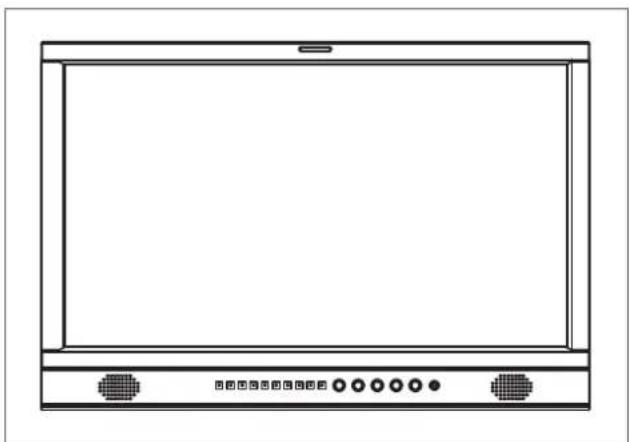
natural_image
Front view of a computer monitor with control buttons at the bottom (no text or symbols visible)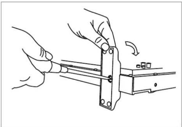
natural_image
Line drawing of hands using a tool to adjust or install a mechanical component (no text or symbols present)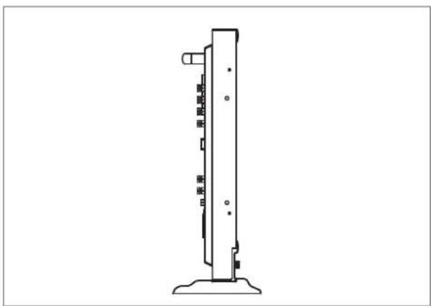
natural_image
Technical line drawing of a vertical mechanical component with mounting base (no text or symbols)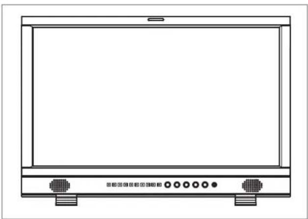
natural_image
Line drawing of a flat-screen monitor with control buttons at the bottom (no text or symbols)Rear panel
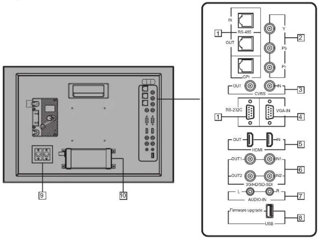
1 REMOTE terminal
Terminal for controlling the monitor by an external control (“External Control” on page 17).
2 Y / Pb / Pr (IN) terminals (BNC)
3 CVBS terminals (BNC)
Input (IN) and output (OUT) terminals for the composite signals.
4 VGA-IN (mini D-sub 15pin)
Input terminal for analog RGB signal. (page) 22
5 HDMI terminal
Input / Output terminal for HDMI signals. The monitor will not display or output HDMI with HDCP protection. ( page 22)
6 E. AUDIO 3G/HD/SD SDI (IN 1, IN 2) terminals (BNC)
Input / Output terminals for the HD/SD SDI signals. ● The terminals accept also EMBEDDED AUDIO signals including up to 16 audio channels with a sampling frequency of 48 kHz.
7 AUDIO (IN) terminals (pin jack)
Input terminals for the analog audio signals. ● Set signal source as ANALOG (CVBS, VGA, YPbPr), the analog audio can be monitored as audio meters or output via Speaker/Headphone.
8 USB socket
Download new firmware to a USB stick, and insert into this socket. By menu operating, the monitor firmware can be upgraded.
9 DC-IN terminal
Main (Back up) power input, connect with DC11V 1-7V 4-pin XLR power adapter. (Pin 1: Negative, Pin 4: Positive)
10 AC-IN terminal
AC power input connector. Connect the provided AC power cord to an AC outlet.
CAUTION
Do not connect the power cord until all other connections are completed.
Note for connections
• Before making any connections, turn off all the equipment.
- Use a cord whose plugs correctly match the terminals on this monitor and the equipment.
- Plugs should be firmly inserted; poor connections could cause noise.
- When unplugging a cord, be sure to grasp its plug and pull it out.
- DO NOT connect the power cord until all connections are complete.
• Refer also to the user manual of each piece of equipment.
Front panel
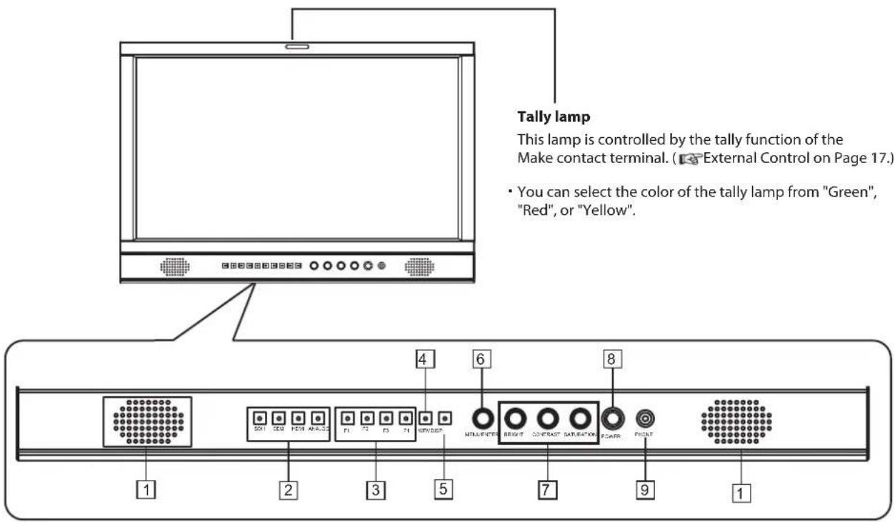
1 Speaker: For SDI/HDMI embedded audio and analog audio monitoring. (Will not work if earphone is plugged in)
2 INPUT SELECT buttons/lamps
Selects an input.
SDI 1: E. AUDIO 3G/HD/SD SDI (IN 1) terminal
SDI 2: E. AUDIO 3G/HD/SD SDI (IN 2) terminal
HDMI:HDMI terminal
ANALOG: select from CVBS, VGA, Y/ Pb / Pr signal
●The lamp for the selected input lights
3 FUNCTION button
You can use the functions assigned to this button.
4 WFM button
Waveform shortcut key, press "WFM" to quickly turn on or turn off the waveform, and select the type of the waveform.
5 DISP button
Press "INFO ON/OFF" to turn on or turn off relevant status information, audio and video waveform.
6 VOLUME MENU/PUSH
When the menu is inactivated, press "VOLUME MENU/PUSH" to turn on the main menu
Revolve "VOLUME MENU/PUSH" to adjust settings or parameters, and press to apply
When the menu is inactivated, revolve "VOLUME MENU/PUSH" to adjust the sound volume
7 Picture adjustment knob
BRIGHT: Adjusts the picture brightness and the default value is 50.
CONTRAST: Adjusts the picture contrast and the default value is 50.
SATURATION: Adjusts the picture saturation and the default value is 50.
* Directly press BRIGHT/CONTRAST/SATURATION knobs, the parameters will recover to default value.
8 POWER
Turns on and off the monitor.
9 PHONE
3.5mm earphone socket, for SDI/HDMI embedded audio and analog audio monitoring.
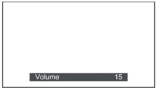
Volume Adjustment
1 When no menu screen is not displayed, revolve the "VOLUME MENU/PUSH" button
2 Clockwise revolve "VOLUME MENU/PUSH" knob to volume up, and anticlockwise revolve to volume down. The volume value range is 0-31.
3 Press the "VOLUME MENU/PUSH" button to finish.
The "Volume" screen disappears automatically if no operations are made for 3 seconds.
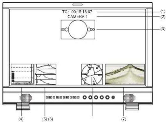
On the Information Display
1 Time code (SDI)
Under SDI input, it can display Time code. If no Time code information is detected, it will be displayed as "TC UNLOCKED". User can set function keys F1 \~ F4 or GPI pins as "Time code" to turn on or off this function.
2 UMD
Set up the UMD under "UMD" submenu.
3 AFD (SDI)
User can set function keys F1\~F4 or GPI pins as "AFD" to turn on or off this function. If no relevant information is detected, it will be displayed as "AFD: UNLOCKED".
4 Audio Bar
Monitor the audio information. The relevant parameters like position, audio channels and blending, etc. can be changed under "Audio Bar" submenu. User can set function Keys F1 \~ F4 or GPI pins as "Audio Bar" to turn on or off this function.
5 Histogram
User can set function Keys F1\~F4 or GPI pins as "Histogram" to turn on or off this function.
6 Vector
The relevant parameters like Vector position, Vector color and Vector blending, etc. can be changed under "Vector" submenu. User can set function Keys F1 \~ F4 or GPI pins as "Vector" to turn on or off this function.
7 Waveform
Press "WFM" on the front panel to turn on/of this function. The relevant parameters like WFM position, WFM color and WFM blending, etc. can be changed under "Waveform" submenu.
On the Status Display
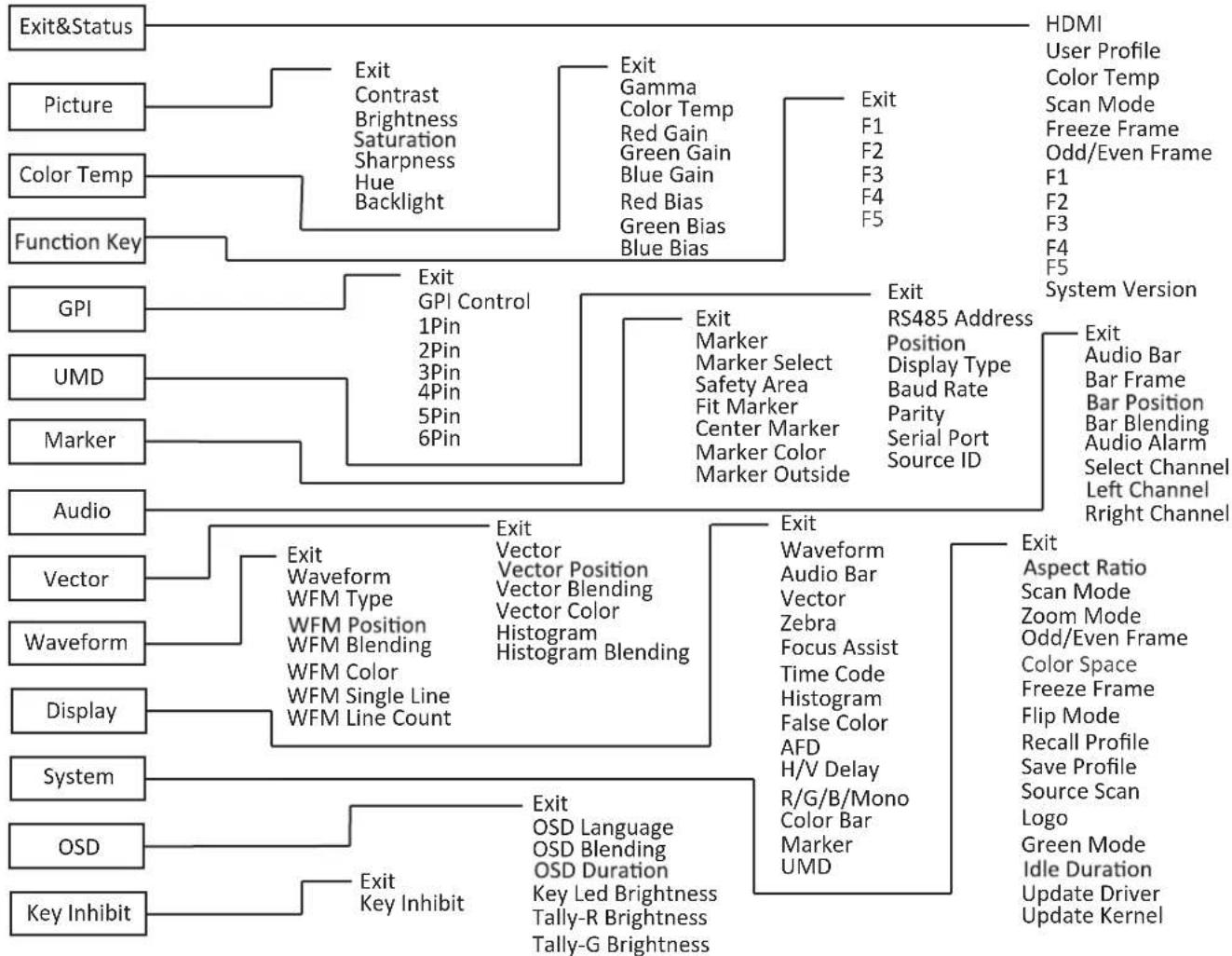
Press "VOLUME MENU/PUSH" button, the main menu will pop up from the left top of the screen, to display the current working status, including:
- Current input video format.
If no video input is locked, it will display "No Signal". - User profile. The monitor can restore 3 user preference settings.
- Color temperature value.
- Scan mode.
- Freeze Frame mode status.
-
Odd/Even Frame mode status.
Not available if the current input signal doesn't support Odd/Even mode. -
The Function Key 1 setting.
-
The Function Key 2 setting.
-
The Function Key 3 setting.
-
The Function Key 4 setting.
-
Current firmware version.
| Main Menu | Status |
| Exit&Status | HDMI XXX 1 |
| Picture | User Profile XX 2 |
| Color Temp | Color Temp XXXX 3 |
| Function Key | Scan Mode XXX 4 |
| GPI | Freeze Frame XXX 5 |
| UMD | Odd/Even Frame XXX 6 |
| Marker | F1 XXX 7 |
| Audio | F2 XXX 8 |
| Vector | F3 XXX 9 |
| Waveform | F4 XXX 10 |
| Display | F5 XXX |
| System | System Version XXX 11 |
| OSD | |
| Key Inhibit |

The Operation Procedure
1 Press the MENU button to display the Main Menu
2 Revolve "VOLUME MENU/PUSH" to select submenu, the selected submenu highlights in yellow, press "VOLUME MENU/PUSH" to apply and enter into the selected submenu's items
3 Revolve "VOLUME MENU/PUSH" to select the item which needed to adjust, press "VOLUME MENU/PUSH", the selected item and its parameters will be highlighted in yellow.
4 Revolve "VOLUME MENU/PUSH" to change the selected item's parameter, press "VOLUME MENU/PUSH" to apply and save the settings.
5 Revolve "VOLUME MENU/PUSH" to select "Exit", press "VOLUME MENU/PUSH" to quit submenu. Select "Exit & Status" under the Main Menu and press to quit Main Menu.
Notice:
The items in gray cannot be set up.
- If there is no operation under the set time, the menu will automatically save settings and quit.
- If the key function function is turned on, except key inhibit function, all other items are in grey. Please turn off the key inh to adjust the items.

Menu Transition Diagram
flowchart
graph TD
    A["Exit&Status"] --> B["Picture"]
    A --> C["Color Temp"]
    A --> D["Function Key"]
    A --> E["GPI"]
    A --> F["UMD"]
    A --> G["Marker"]
    A --> H["Audio"]
    A --> I["Vector"]
    A --> J["Waveform"]
    A --> K["Display"]
    A --> L["System"]
    A --> M["OSD"]
    A --> N["Key Inhibit"]

    B --> O["Exit"]
    B --> P["Contrast"]
    B --> Q["Brightness"]
    B --> R["Saturation"]
    B --> S["Sharpness"]
    B --> T["Hue"]
    B --> U["Backlight"]

    C --> V["Exit"]
    C --> W["Gamma"]
    C --> X["Color Temp"]
    C --> Y["Red Gain"]
    C --> Z["Green Gain"]
    C --> AA["Blue Gain"]
    C --> AB["Red Bias"]
    C --> AC["Green Bias"]
    C --> AD["Blue Bias"]

    D --> AE["Exit"]
    D --> AF["GPI Control"]
    D --> AG["1Pin"]
    D --> AH["2Pin"]
    D --> AI["3Pin"]
    D --> AJ["4Pin"]
    D --> AK["5Pin"]
    D --> AL["6Pin"]

    E --> AM["Exit"]
    E --> AN["Marker"]
    E --> AO["Marker Select"]
    E --> AP["Safety Area"]
    E --> AQ["Fit Marker"]
    E --> AR["Center Marker"]
    E --> AS["Marker Color"]
    E --> AT["Marker Outside"]

    F --> AU["Exit"]
    F --> AV["RS485 Address"]
    F --> AW["Position"]
    F --> AX["Display Type"]
    F --> AY["Baud Rate"]
    F --> AZ["Parity"]
    F --> BA["Serial Port"]
    F --> BB["Source ID"]

    H --> BC["Exit"]
    H --> BD["Audio Bar"]
    H --> BE["Bar Frame"]
    H --> BF["Bar Position"]
    H --> BG["Bar Blending"]
    H --> BH["Audio Alarm"]
    H --> BI["Select Channel"]
    H --> BJ["Left Channel"]
    H --> BK["Right Channel"]

    I --> BL["Exit"]
    I --> BM["Waveform"]
    I --> BN["Vector Type"]
    I --> BO["Vector Position"]
    I --> BP["Vector Blending"]
    I --> BQ["Vector Color"]
    I --> BR["Vector Blending"]
    I --> BS["Vector Color Histogram Blending"]

    J --> BT["Exit"]
    J --> BU["Waveform"]
    J --> BV["Audio Bar"]
    J --> BW["Vector"]
    J --> BX["Zebra"]
    J --> BY["Focus Assist"]
    J --> BZ["Time Code Histogram False Color AFD H/V Delay R/G/B/Mono Color Bar Marker UMD"]

    K --> CA["Exit"]
    K --> CB["Aspect Ratio Scan Mode Zoom Mode Odd/Even Frame Color Space Freeze Frame Flip Mode Recall Profile Save Profile Source Scan Logo Green Mode Idle Duration Update Driver Update Kernel"]

    L --> CD["Exit"]
    L --> CE["Key Inhibit"]

    M --> CF["Exit"]
    M --> CG["Key Inhibit"]

    N --> CH["Exit"]
    N --> CI["Key Inhibit"]

    O --> CJ["HDMI User Profile Color Temp Scan Mode Freeze Frame Odd/Even Frame F1 F2 F3 F4 F5 System Version"]

    P --> CK["HDMI User Profile Color Temp Scan Mode Freeze Frame Odd/Even Frame F1 F2 F3 F4 F5 System Version"]

    Q --> CR["HDMI User Profile Color Temp Scan Mode Freeze Frame Odd/Even Frame F1 F2 F3 F4 F5 System Version"]

    R --> CS["HDMI User Profile Color Temp Scan Mode Freeze Frame Odd/Even Frame F1 F2 F3 F4 F5 System Version"]

    S --> CT["HDMI User Profile Color Temp Scan Mode Freeze Frame Odd/Even Frame F1 F2 F3 F4 F5 System Version"]

    T --> CU["HDMI User Profile Color Temp Scan Mode Freeze Frame Odd/Even Frame F1 F2 F3 F4 F5 System Version"]

    U --> CV["HDMI User Profile Color Temp Scan Mode Freeze Frame Odd/Even Frame F1 F2 F3 F4 F5 System Version"]

    V --> CW["HDMI User Profile Color Temp Scan Mode Freeze Frame Odd/Even Frame F1 F2 F3 F4 F5 System Version"]

    W --> CX["HDMI User Profile Color Temp Scan Mode Freeze Frame Odd/Even Frame F1 F2 F3 F4 F5 System Version"]

    X --> CY["HDMI User Profile Color Temp Scan Mode Freeze Frame Odd/Even Frame F1 F2 F3 F4 F5 System Version"]

    Y --> CZ["HDMI User Profile Color Temp Scan Mode Freeze Frame Odd/Even Frame F1 F2 F3 F4 F5 System Version"]

    Z --> DA["HDMI User Profile Color Temp Scan Mode Freeze Frame Odd/Even Frame F1 F2 F3 F4 F5 System Version"]

    AA --> DB["HDMI User Profile Color Temp Scan Mode Freeze Frame Odd/Even Frame F1 F2 F3 F4 F5 System Version"]

    AB --> DC["HDMI User Profile Color Temp Scan Mode Freeze Frame Odd/Even Frame F1 F2 F3 F4 F5 System Version"]

    AC --> DD["HDMI User Profile Color Temp Scan Mode Freeze Frame Odd/Even Frame F1 F2 F3 F4 F5 System Version"]

    AD --> DE["HDMI User Profile Color Temp Scan Mode Freeze Frame Odd/Even Frame F1 F2 F3 F4 F5 System Version"]

    AE --> DF["HDMI User Profile Color Temp Scan Mode Freeze Frame Odd/Even Frame F1 F2 F3 F4 F5 System Version"]

    AF --> DG["HDMI User Profile Color Temp Scan Mode Freeze Frame Odd/Even Frame F1 F2 F3 F4 F5 System Version"]

    AG --> DH["HDMI User Profile Color Temp Scan Mode Freeze Frame Odd/Even Frame F1 F2 F3 F4 F5 System Version"]

    AH --> DI["HDMI User Profile Color Temp Scan Mode Freeze Frame Odd/Even Frame F1 F2 F3 F4 F5 System Version"]

    AI --> DJ["HDMI User Profile Color Temp Scan Mode Freeze Frame Odd/Even Frame F1 F2 F3 F4 F5 System Version"]

    AJ --> DE
    AJ --> DC
- "Exit &Status" is only displayed, and cannot be set/changed.

Main Menu
Picture Function
Setting for the picture quality.
| Item | To do | Setting value |
| Exit | Return Main Menu | |
| Contrast | Adjusts the contrast of the display. | 0 to 100 |
| Brightness | Adjusts the brightness of the display. | 0 to 100 |
| Saturation | Adjusts the saturation of the display. | 0 to 100 |
| Sharpness | Adjusts the sharpness of the display. | 0 to 100 |
| Hue | Adjusts the hue of the display. | 0 to 100 |
| Backlight | Adjusts the backlight of the display. | 0 to 100 |
Color Temperature
Adjusts the R/G/B Gain and Bias, and Gamma Preset
| Item | To do | Setting value |
| Exit | Return Main Menu | |
| Gamma | Select the Gamma correction value. | 2.2 (equivalent to Y 2.2)2.4 (equivalent to Y 2.4)2.6 (equivalent to Y 2.6) |
| Color Temp | Select the color temperature Mode. | 5600K、6500K、9300K、User |
| Red Gain | Adjusts the Red Gain | 0 to 255 |
| Green Gain | Adjusts the Green Gain | 0 to 255 |
| Blue Gain | Adjusts the Blue Gain | 0 to 255 |
| Red Bias | Adjusts the Red Bias | 0 to 255 |
| Green Bias | Adjusts the Green Bias | 0 to 255 |
| Blue Bias | Adjusts the Blue Bias | 0 to 255 |
Only "Color Temp" is set to "User", the Red/Blue/Green Gain or Red/Blue/Green Bias can be adjusted
Function Key
Set short-cut functions for F1-F4
| Item | To do | Setting value |
| Exit | Return Main Menu | |
| F1 | Assign functions to the function keys F1 - F4 on the front key board | Audio Bar, Histogram, False Color, AFD, H/V Delay, R/G/B/Mono, Marker, Color Bar, UMD, Audio Alarm, Odd/Even Frame, Focus Assist, Aspect Ratio, Scan Mode, Zoom Mode, Mute, Freeze Frame, Flip Mode, CVBS, YPbPr, VGA, Color Temp, Time Code, Zebra, Vector. |
| F2 | ||
| F3 | ||
| F4 |
For example: Set F3 to "R/G/B/Mono" under "Function key" submenu. User can press F3 on the front panel to adjust the parameters of "R/G/B/Mono", and the "R/G/B/Mono" will change and follow the sequence: Blue Only → Red Only → Green Only → Mono → Off.
GPI
Setting functions for external control
| Item | Setting valueTo do | |
| Exit | Return Main Menu | |
| GPI Control*1 | Enable GPI control | ON, OFF |
| 1 Pin | Assign functions to the GPI terminals | Red Tally, Green Tally, Yellow Tally, Aspect Ratio, Scan Mode, Zoom Mode, Mute, Freeze Frame, Flip Mode, Color Temp, Time code, Zebra, Vector, Audio Bar, Histogram, False Color, AFD, H/V Delay, R/G/B/Mono, Marker, Color Bar, UMD, Audio Alarm, Odd/Even Frame, Focus Assist |
| 2 Pin | ||
| 3 Pin | ||
| 4 Pin | ||
| 5 Pin | ||
| 6 Pin |
*1 When "GPI control" is set to "On", the monitor can be operated through external GPI control unit.
Example 1: Under "GPI" submenu, set "GPI control" to "On", set "2 Pin" to "Red Tally", when the pin 2 of the external GPI control unit is connected with ground, the Tally light on the front panel will turn red. When disconnected, the tally light will turn off.
Example 2: Under "GPI" submenu, set "GPI control" to "On", set "6 Pin" to "Scan Mode", when the pin 6 of the external GPI control unit is connected with ground, the Scan mode will change and follow the sequence: "Normal" >"Overscan" >"Native".
Menu Configuration (cont.)
UMD
Setting UMD control parameters (TSL UMD Protocol V3.1/4.0, provided by Television System LTD.)
| Item | To do | Setting value |
| Exit | Return Main Menu | |
| Address setting1 to 126: Set a particular address | 1 to 126RS485 Address | |
| Position | Position setting | Top、Bottom |
| Display Type | Choose Display Type | Source ID、UMD |
| Baud Rate | Baud Rate setting | 38400、9600、19200 |
| Parity | Parity setting | Even、None |
| Serial Port | Choose Serial Port | RS485、RS232 |
| Source ID | Setting of "Source ID"*1 |
*1 Setting of "Source ID"
(1) Change the input to one that you want to assign a video source name for.
(2) Select "Source ID"
(3) revolve the "MENU" button to select the first character.
Each time you revolve the "MENU" button, the character changes as follows.

(4) Press the "MENU" button to move the arrow to the next space.
The characters entered before moving the arrow are memorized.
(5) Repeat steps (3) and (4) (10 characters at maximum).
(6) Press MENU button to store the name.
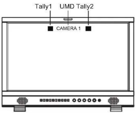
- UMD setup
(1) Connect the external control equipment with the monitor
(2) Set "Display Type" to "UMD"
(3) Set "Serial Port" to RS485 or RS232 according to the port type of external
control equipment
(4) Make sure the "address", "Baud Rate", "Parity" the same
(5) Adjust the external control equipment and send UMD command, the UMD information will be displayed as the right photo.
User can set the character and color of the UMD and the color of Tally1 and 2.
Marker
Settings for marker functions
| Item | To do | Setting value |
| Exit | Return Main Menu | |
| Marker | Display settingOn: Displayed, Off: Not displayed | Off、On |
| Marker Select | Adjust the ratio of marker | Off、4:3、13:9、14:9、15:9、16:9、1.85:1、2.35:1 |
| Safety Area | Safety Area setting | Off、80%、85%、90%、93%、95% |
| Fit Marker*1 | Fit Marker setting | Off、On |
| Center Marker | Display settingOn: Displayed, Off: Not displayed | Off、On |
| Marker Color | Marker color setting | White、Red、Green、Blue、Black、Gray |
| Marker Outside | Marker Outside color setting | Off、Gray、Black |
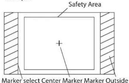
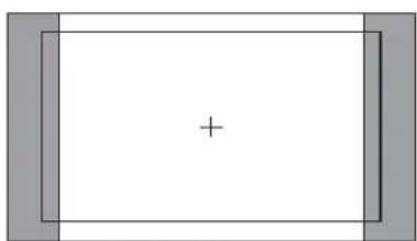
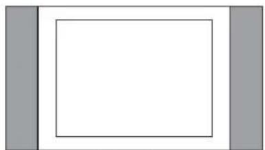
*1 When "Fit Marker" is Off, the size of safety area is benchmarked against the actual display screen, accounting for 80% \~ 95% of actual display screen. When "Fit Marker" is On, the size of safety area is benchmarked against the area inside the scales marker, accounting for 80% \~ 95% of the area inside the scales marker.
Example:
natural_image
Simple geometric diagram with a central plus sign inside a rectangle, flanked by gray rectangular borders (no text or symbols)Marker: 4:3
Safety Area: 85%
Center Marker: On
Fit Marker: Off
natural_image
Simple geometric diagram with a white rectangle and two gray vertical bars on the left (no text or symbols)Marker: 4:3
Safety Area: 85%
Center Marker: Off
Fit Marker: On
Audio Setting
Setting for the audio meters and channel selection
| Item | To do | Setting value | |||
| Exit | Return Main Menu | ||||
| Audio Bar | Display settingOn: Displayed, Off: Not displayed | On、Off | |||
| Bar Frame*1 | Display settingOn: Displayed,Off: Not displayed 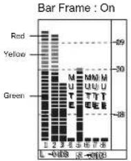 | Bar Frame : Off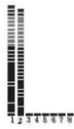 | On、Off | ||
| Bar Position | Bar Position setting | Top Right、Bottom Left、Bottom Right、Top Left | |||
| Bar Blending | Bar Blending settingOff: Set the background of the bar display black.Low: Set the background of the bar display grayHigh: Set the background of the bar display transparent. | Low、Off High | |||
| Audio Alarm*2 | Display settingOn: Displayed,Off: Not displayed 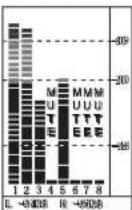 | Audio Alarm : Off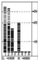 | Off、On | ||
| Select Channel*3 | Select Channel setting [YHTA] 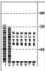 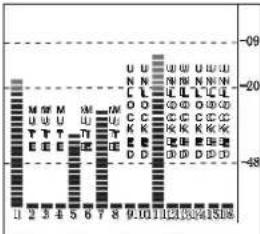 | HDMI: Channel 1-2、1-8SDI: Channel 1-2、1-8、1-16ANALOG: Channel 1-2 | |||
| Left ChannelRight Channel*4 | Select the audio left and right channels to output.The current left channel number displays green, and the right channel number displays red. 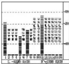 Left Channel.5 Green Right Channel.11 Red Left Channel.5 Green Right Channel.11 Red | HDMI: Channel 1-8SDI: Channel 1-16 | |||
*1 When "Bar Frame" is set to "Off", only the audio meter will be displayed
When "Bar Frame" is set to "On", frame and real-time audio value will be displayed.
*2 When "Audio Alarm" is set to "On", if no embedded audio is detected, the audio bar will display "UNLOCKED". If the audio value is too low, the audio bar will display "MUTE".
*3 Select Channel
Under analog signal, only channel1-2 can be displayed.
Under HDMI signal, channel1-2 and 1-8 can be selected.
Under SDI signal, channel 1-2, 1-8 and 1-16 can be selected
*4 Audio channels can be selected to output according to the requirements.
When the current "Select Channel" is set to "Channel1-2", the left channel and right channel output can be selected from Channel1 or channel2.
When the current "Select Channel" is set to "Channel1-8", the left channel and right channel output can be selected from Channel1 to channel8.
When the current "Select Channel" is set to "Channel1-16", the left channel and right channel output can be selected from Channel1 to channel16.
In audio bar, the left channel information will be in green, and the right channel information will be in red.
Vector
Setting for Vector scope and Histogram patterns
| Item | To do | Setting value |
| Exit | Return Main Menu | |
| Vector | Display settingOn: Displayed, Off: Not displayed | Off、On |
| Vector Position settingVector Position | Bottom Right、Center、Top Left、Top Right、Bottom Left | |
| Vector Blending | Vector Blending settingOff: Set the background of the vector display black.Low: Set the background of the vector display grayHigh: Set the background of the vector display transparent. | Off、Low、High |
| Vector Color | Vector Color setting | Color、White、Green、False Color |
| Histogram | Display settingOn: Displayed, Off: Not displayed | Off、On |
| Histogram Blending | Histogram Blending settingOff: Set the background of the histogram display black.Low: Set the background of the histogram display grayHigh: Set the background of the histogram display transparent. | Off、Low、High |
Waveform
Setting for Waveform patterns
| Item | To do | Setting value |
| Exit | Return Main Menu | |
| Waveform | Display settingOn: Displayed, Off: Not displayed | Off、On |
| WFM Type | Waveform type setting | Y、Cb、Cr、R、G、B |
| WFM Position | Waveform position settingWaveform blending setting | Bottom Left、Bottom Right、Center、Top Left、Top Right |
| WFM Blending | Off: Set the background of the waveform display black.Low: Set the background of the waveform display grayHigh: Set the background of the waveform display transparent. | Low、High、Off |
| WFM Color | Waveform color setting | White、Green、False Color |
| WFM Single Line | Display settingOn: Displayed, Off: Not displayed | Off、On |
| WFM Line Count | WFM Line Count setting | 0 to 1079 |
*1: Only the "WFM Single Line" is set to "ON", the "WFM Line Count" can be adjusted.
"WFM Single Line" is to display the selected line waveform of "WFM Line Count"
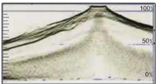
area
| Time | Value | |------|-------| | 0 | 0% | | 5 | 50% | | 10 | 100% |WFM Single Line Off
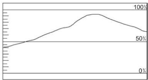
line
| Point | Value | |-------|-------| | 1 | 50% | | 2 | 75% | | 3 | 100% |WFM Single Line: On
Display
On/off control center for all function patterns display
| Item | To do | Setting value |
| Exit | Return Main Menu | |
| Waveform | Display settingOn: Displayed, Off: Not displayed | Off、On |
| Audio Bar | Display settingOn: Displayed, Off: Not displayed | Off、On |
| Vector | Display settingOn: Displayed, Off: Not displayed | Off、On |
| Zebra | Display settingOn: Displayed, Off: Not displayed | Off、On |
| Focus Assist | Focus Assist setting | Off、Blue、Red |
| Time Code | Display settingOn: Displayed, Off: Not displayed | Off、On |
| Histogram | Display settingOn: Displayed, Off: Not displayed | Off、On |
| False Color | Display settingOn: Displayed, Off: Not displayed | Off、On |
| AFD | Display settingOn: Displayed, Off: Not displayed | Off、On |
| H/V Delay | Display settingOn: Displayed, Off: Not displayed | Off、On |
| R/G/B/Mono | R/G/B/Mono setting | Off、Blue Only、Red Only、Green Only、Mono |
| Color Bar | Display settingOn: Displayed, Off: Not displayed | Off、On |
| Marker | Display settingOn: Displayed, Off: Not displayed | Off、On |
| UMD | Display settingOn: Displayed, Off: Not displayed | Off、On |
System
General system mode settings and firmware upgrade
| Item | To do | Setting value |
| Exit | Return Main Menu | |
| Aspect Ratio | Aspect Ratio setting | 16:9、4:3 |
| Scan Mode | Scan Mode setting | Normal、OverScan、Native |
| Zoom Mode | Zoom Mode setting | Off、Zoom1、Zoom2 |
| Odd/Even Frame | Odd/Even Mode setting | Off、Odd Mode、Even Mode |
| Freeze Frame | Display settingOn: Displayed, Off: Not displayed | Off、On |
| Flip Mode | Flip Mode settingABCDEFH FlipV Flip H/V Flip | Off、H Flip、V Flip、H/V Flip |
| Recall Profile | Loading Factory settings and User presetsDefault: Recover all settings to factory settingUser 1/2/3: Load the User settings 1/2/3 | Factory、User1、User2、User3 |
| Save Profile | Save current User settingsUser 1/2/3: Save the current settings to User 1/2/3 | User1、User2、User3 |
| Source Scan*1 | Settings for auto-scan input signals when switch on the monitorOn: Automatically scanOff: Stays the signal source when the monitor is switched off | On、Off |
| Logo*2 | Settings to display Switch on logo or notOn: Display, Off: Not display | On、Off |
| Green Mode*3 | Display settings when in Energy Save mode | Black Backlight、Standby、Gray Backlight |
| Idle Duration | Set an idle time to enter Energy Save mode | Off、30Sec、2Hours、4Hours |
| Update Driver*4 | Enter to upgrade Driver (USB firmware upgrade) | No、Yes |
| Update Kernel*5 | Enter to upgrade Kernel (USB firmware upgrade) | No、Yes |
*1 Source Scan
When set to "Yes", next time switch on the monitor, the monitor will automatically scan the available signal source with the sequence of "SDI1 >SDI2 >HDMI >YPbPr >VGA >CVBS".
*2 Logo
When powered on, the screen will display ProHD logo.
*3 Green Mode
When no recognized signal is detected and operation time reaches the time selected in "Idle Duration", the monitor will turn to green energy saving mode: "Green mode".
Under standby, Gray Backlight, Blacklight mode, press any button on the front panel, the monitor will be back to normal status.
\*4, \*5 Update Driver/ Kernel
Operation steps:
- Download latest firmware files to USB disk, switch on the monitor, and insert to the USB port on rear panel of the monitor
- Press "MENU/ENTER", enter "Main Menu" - "System", and select "Update Driver" or "Update Kernel".
- Set "Yes", the monitor will upgrade automatically.
| Main Menu | System | ||
| Exit | |||
| Exit&Status | > | Aspect Ratio | XX |
| Picture | > | Scan Mode | XXXX |
| Color Temp | > | Zoom Mode | XXX |
| Function Key | > | Odd/Even Frame | XXX |
| GPI | > | Color Space | XXX |
| UMD | > | Freeze Frame | XXX |
| Marker | > | Flip Mode | XXX |
| Audio | > | Recall Profile | XXX |
| Vector | > | Save Profile | XXX |
| Waveform | > | Source Scan | XXX |
| Display | > | Logo | XXX |
| System | > | Green Mode | XXX |
| OSD | > | Idle Duration | XXX |
| Key Inhibit | > | Update Driver | Yes |
| Update Kernel | XXX | ||
- During firmware upgrade, the screen will display progress percentage. Please do not cut off power during the upgrade.
| USB firmware upgrade | |
| Firmware Upgrading... | 37% |
| Caution! DO NOT cut off power during firmware upgrade. | |
- When succeed, the monitor will automatically re-start, and then the upgrade will be finished.
OSD
Adjust the OSD display size, color, duration, and TALLY light/keyboard light settings
| Item | To do | Setting value |
| Exit | Return Main Menu | |
| OSD Language | OSD Language setting | English、Chinese |
| OSD Blending | OSD Blending setting | Low、Medium、High、Off |
| OSD Duration*1 | OSD Duration setting | 10Sec、15Sec、30Sec、60Sec |
| OSD Zoom | OSD Zoom setting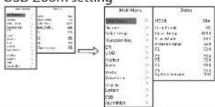 | Off、On |
| Key Led Brightness | Key Led Brightness setting | Low、Medium、High、Off |
| Tally-R Brightness | Set the brightness of tally when is red | High、Low、Medium |
| Tally-G Brightness | Set the brightness of tally when is green | High、Low、Medium |
*1 During this period of time, if there's no operation to the menu, the menu will automatically quit.
Key Inhibit
To lock the keyboard for safety operation
| Item | To do | Setting value |
| Exit | Return Main Menu | |
| Key Inhibit | Key Inhibit setting | Off、On |
If the "Key Inhibit" is "On", there is no response when all the buttons expert "VOLUME MENU/PUSH" are pressed, the screen will be displayed as "Key Inhibit".
User can set "Key Inhibit" under "key Inhibit" submenu to "Off" to recover the functions of all buttons.
About the external control
This monitor has three external control terminals.
- RS-485 terminal (RJ-45): Controls the monitor with the RS-485 system. The terminal is to connect with TallyMan system of UMD application.
- RS-232C terminal (D-sub 9-pin): Controls the monitor with the RS-232C system (TallyMan) The terminal is to connect with TallyMan system of UMD application.
- Make contact terminal (RJ-45): Controls the monitor by short-circuiting the corresponding pin terminal to the GND pin terminal, or disconnecting (opening) it. The terminal is to assign functions for GPI controlling.
Using the UMD control
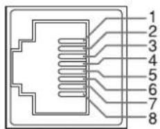
This is a female terminal.
| Pin No. | IN terminal signal | OUT terminal signal |
| 1 | TXD + TXD + | |
| 2 | TXD - TXD - | |
| 3 | RXD + RXD + | |
| 4 | NC NC | |
| 5 | NC NC | |
| 6 | RXD - RXD - | |
| 7 | NC NC | |
| 8 | GND GND |
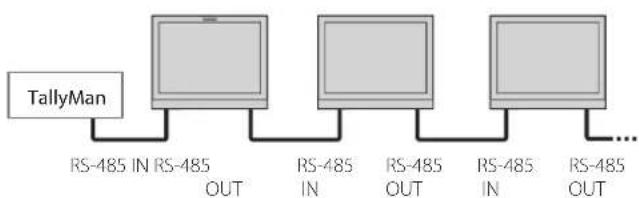
flowchart
graph LR
    A["TallyMan"] --> B["RS-485 IN RS-485 OUT"]
    B --> C["RS-485 IN"]
    C --> D["RS-485 OUT"]
    D --> E["RS-485 IN"]
    E --> F["..."]
    style A fill:#f9f,stroke:#333
    style F fill:#f9f,stroke:#333
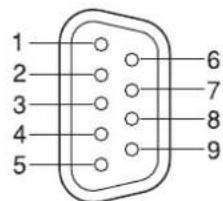
This is a female terminal.
| Pin No. | Signal | |
| 1 | NC | |
| 2 | RXD | |
| 3 | TXD | |
| 4 | NC | |
| 5 | GND | |
| 6 | NC | |
| 7 | RTS | |
| 8 | CTS | |
| 9 | NC | |
● The 7th terminal and the 8th terminal are connected.
Using the GPI control
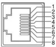
This is a female terminal.
| Pin No | Pin name |
| 1 GPI 1 | |
| 2 GPI 2 | |
| 3 GPI 3 | |
| 4 GPI 4 | |
| 5 GPI 5 | |
| 6 GPI 6 | |
| 7 NC | |
| 8 GND |
To assign the functions to the pin terminals
1 Select "GPI" on the Main Menu.
2 Set "GPI control" to "ON".
3 Select a pin name ("Pin1" - "Pin6") for which you want to assign a function, then select the function you want to assign.
Operation of the external control
1 Operate each function by short-circuiting the corresponding pin terminal to the 8th pin terminal (GND) or opening it.
| Display | Functions to be controlled | Opening | Short-circuiting |
| No function | — | — | |
| Red Tally | Tally light red | off | Red |
| Green Tally | Tally light green | off | Green |
| Yellow Tally | Tally light yellow | off | Yellow |
| Aspect Ratio | Changes the aspect ratio. | *1 | |
| Scan Mode | Changes the scan mode | *2 | |
| Zoom Mode | Changes zoom mode | *3 | |
| Mute | Mute setting | *4 | |
| Freeze Frame | Freeze Frame setting | *4 | |
| Time code | Time code display | *4 | |
| Zebra | Zebra display | *4 | |
| Vector | Vector display | *4 | |
| Audio Bar | Audio Bar display | *4 | |
| Histogram | Histogram display | *4 | |
| False Color | False Color display | *4 | |
| AFD | AFD display | *4 | |
| H/V Delay | H/V Delay display | *4 | |
| Marker | Marker display | *4 | |
| Color Bar | Color Bar display | *4 | |
| UMD | UMD display | *4 | |
| Audio Alarm | Audio Alarm display | *4 | |
| Color Temp | Color Temp setting | *5 | |
| R/G/B/Mono | R/G/B/Mono setting | *6 | |
| Flip Mode | Flip Mode setting | *7 | |
| Odd/Even Frame | Odd/Even Mode setting | *8 |
*1 For every short-circuiting, the Aspect Ratio value changes in the order of 16:9 >4:3
*2 For every short-circuiting, the Scan Mode value changes in the order of Normal > Overscan > Native
*3 For every short-circuiting, the Zoom Mode value changes in the order of Off → Zoom1 → Zoom2
*4 For every short-circuiting, the value changes in the order of On → Off
*5 For every short-circuiting, the Color Temp value changes in the order of 6500K > 5600K > 9300K > User
*6 For every short-circuiting, the R/G/B/Mono value changes in the order of Off → Blue Only → Red Only → Green Only → Mono
*7 For every short-circuiting, the Flip Mode value changes in the order of Off → H Llip → V Flip → H/V Flip
*8 For every short-circuiting, the Odd/Even Frame Mode value changes in the order of Off → Odd Mode → Even Mode
Solutions to common problems related to the monitor are described here. If none of the solutions presented here solve the problem, unplug the monitor and consult an authorized dealer or service center.
| Symptom | Probable cause and corrective action | Page |
| No power supply. | ● press "POWER" button● Firmly insert the AC power plug. | 87 |
| No picture with the power on. | ● Select the correct input using the INPUT SELECT buttons.● Connect the connecting cable firmly.● Turn on the power of the connected component and set the output correctly.● Check whether the input signal format is acceptable on the monitor. | 87—21 |
| No sound. | ● Adjust the volume level.● Deactivate the muting function.● Connect the connecting cable firmly.● Turn on the power of the connected component and set the output correctly. | 9117— |
| No Sync | ● Select the correct input using the INPUT SELECT buttons.● Connect the connecting cable firmly.● Turn on the power of the connected component and output video signals. Or, check whether the video output of the component (video output setting of the VCR or graphic board of the computer) is set correctly. | 87— |
| Wrong color, no color. | ● Adjust each picture adjustment knob on the front panel or adjust the items of "Picture" in the Main Menu.● Adjust the "Recall profile" to "Default" under "System" submenu● Turn the Blue only/ Red Only/ Green Only/Mono off under R/G/B/Mono submenu● Turn off the "Focus Assist" function● Turn off the "False Color" function | 8, 111515, 1715, 1715, 17 |
| The picture becomes blurred. | ● Adjust the picture contrast or brightness by using the adjustment knobs on the front panel. Or, adjust "Contrast" or "Brightness" of "Picture" in the Main Menu. | 8, 11 |
| Buttons on the monitor do not work. | ● Set "Key Inhibit" in the Main Menu to "Off" | 16 |
The following are not malfunctions.
- When a still image is displayed for a long time, it may remain indistinctly on the screen after the picture has changed. Though the remaining picture will disappear after a while, there may be a case that it remains for a long period depending on the length of time the still image was displayed for. This is due to the characteristics of the LCD display and is not a malfunction.
- Red spots, blue spots and green spots on the panel surface are a normal characteristic of LCD panels, and not a problem. The LCD panel is built with very high precision technology; however, be aware that a few pixels may be missing or constantly lit.
The following symptoms are problems only when pictures or sounds are not played back normally.
A slight electric shock occurs when you touch the LCD panel.
● The top and/or rear panel of the monitor becomes hot.
● The monitor emits a cracking noise.
● The monitor emits a mechanical noise.

General
| Model name DT-N24F | |
| Type Multi format LCD monitor | |
| Screen size Type 23.8 wide format | |
| Aspect ratio 16:9 | |
| Horizontal/vertical frequency (computer signal) | H: 64 kHz - 83 kHzV: 50 Hz - 75 Hz* Some signals within this frequency range may not be displayed |
| Compliant video signal format | “Available signals” on page 21 |
| Format 3G SDI: SMPTE-425M-A/BHD SDI: BTA S-004C, SMPTE292M, SMPTE-425M-A/B, SMPTE-274M, SMPTE-RP211, SMPTE-296MSD SDI: SMPTE-125M, ITU-R BT.6562K: SMPTE ST 2048-1: 2011EMBEDDED AUDIO: SMPTE299M, SMPTE272M | |
| Audio output Internal speaker: 2.5W+2.5W(8Ω) | |
| Operating conditions | Operating temperature: 0°C - 40°C (41°F - 95°F)Operating humidity: 20% - 80% (non-condensing)(Slightly variable depending on ambient conditions for installation.) |
| Power requirements AC 120 V / AC 220 - 240 V, 50 Hz/60 Hz; DC11 ~ 17V | |
| Rated current 1.5A (AC 100V ~ 240V)3.0A (DC11 ~ 17V) | |
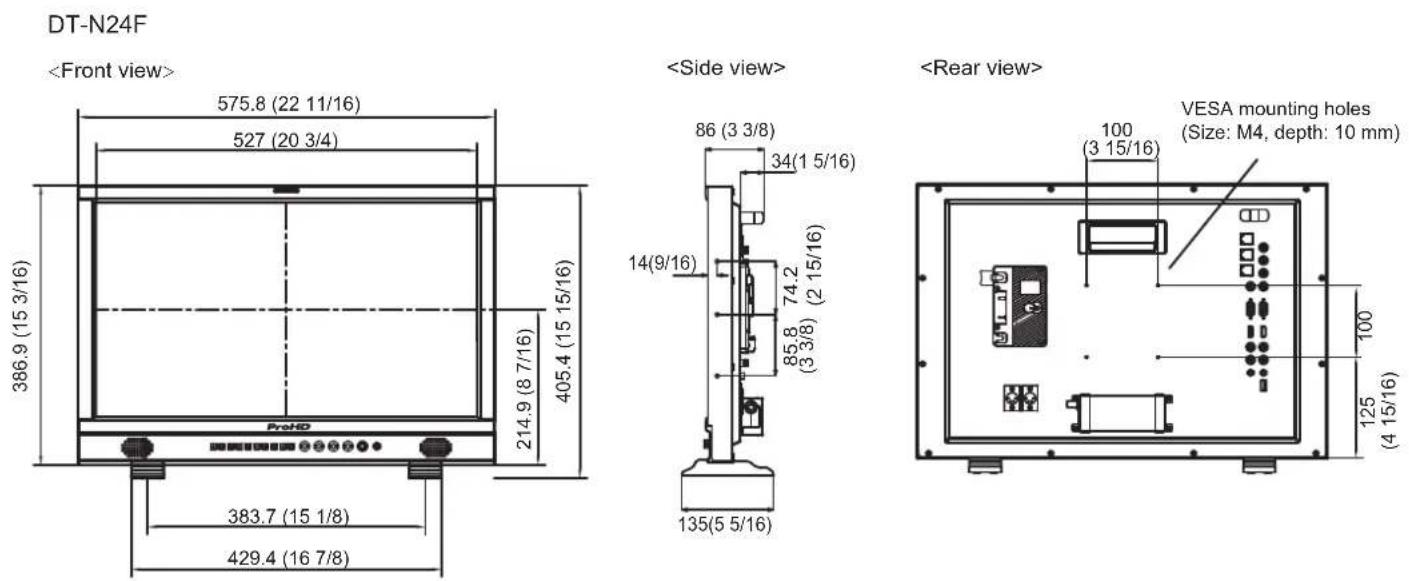
| External dimensions (excluding protruding parts) | with the stand without the standWidth: 575.8 mm (22 1/2") 575.8mm (22 1/2")Height: 405.4 mm (16") 386.9 mm (15 1/4")Depth: 135 mm (5 1/4") 86 mm (3 1/4") |
| Weight | 7.2 kg(15.9 lbs) (with the stand) |
| Accessories AC power cord x 1 | |

LCD panel
| Type | 23.8" wide, active matrix TFT |
| Effective screen size | Width: 527.04 mm (20 3/4")Height: 296.46 mm (11 11/16")Diagonal: 604.7 mm (23 13/16") |
| Number of pixels displayed 1920 x 1080 | |
| Number of colors displayed 1670 million | |
| Viewing angle (TYP.) 178° (Horizontally), 178° (Vertically) | |
| Brightness (TYP.) 250 cd/m | ^2 |
| Contrast ratio (TYP.) | 1000:1 |

Input/output terminals
| Video | CVBS | Input/output of composite signal: 1 line, BNC connector x 2, 1 V (p-p), 75 Ω* The input (IN) and output (OUT) terminals |
| HDMI | HDMI connector x 2(IN and OUT) | |
| VGA | 1 Line, mini D-SUB 15pin x1(IN) | |
| YPbPr | Y: 1 V(p-p), 75 Ω(with sync)Pb : 0.7 V (p-p), 75 ΩPr: 0.7 V (p-p), 75 Ω | |
| E. AUDIO 3G/ HD/SD SDI | Digital signal input (compatible with EMBEDDED AUDIO signals): auto detection, 2 line, BNC connector x 2 | |
| E. AUDIO 3G/ HD/SD SDI | Digital signal output (compatible with EMBEDDED AUDIO signals): auto detection, 2 line, BNC connector x 2 | |
| Audio | AUDIO (IN) | Analog audio signal input: 1 line, RCA connector x 2, 500 mV (rms), high impedance |
| AUDIO (MONITOR OUT) | Speaker: 2.5W+2.5W(8Ω)3.5mm phone | |
| External control | GPI (MAKE) | “Using the GPI control” on page 17. |
| UMD (RS-485) | “Using the UMD control” on page 17. | |
| UMD (RS-232C) |

Dimensions
Unit: mm (inch)

Available signals
The following signals are available for this monitor. Video signals
| No. Signal name | Signal format shown in the status display | Input terminal | |||||
| CVBS YPbPr | VGA SDI HDMI | ||||||
| 1 | NTSC | NTSC | √ | — | — | — | — |
| 2 | NTSC 4.43 | NTSC | √ | — | — | — | — |
| 3 | PAL-M | PAL | √ | — | — | — | — |
| 4 | PAL | PAL | √ | — | — | — | — |
| 5 | PAL-N | PAL | — | — | — | — | — |
| 6 | SECAM | SECAM | √ | — | — | — | — |
| 7 | 480/60i | 480i | — | √ | — | √ | √ |
| 8 | 480/59.94i | 480i | — | √ | — | √ | √ |
| 9 | 576/50i | 576i | — | √ | — | √ | √ |
| 10 | 480/60p | 480p | — | √ | — | — | √ |
| 11 | 480/59.94p | 480p | — | √ | — | — | √ |
| 12 | 576/50p | 576p | — | √ | — | — | √ |
| 13 | 640*480/60p | 640*480 | — | √ | √ | — | √ |
| 14 | 640*480/59.94p | 640*480 | — | √ | √ | — | √ |
| 15 | 720/60p | 720p60 | — | √ | — | √ | √ |
| 16 | 720/59.94p | 720p60 | — | √ | — | √ | √ |
| 17 | 720/50p | 720p50 | — | √ | — | √ | √ |
| 18 | 1080/60i | 1080i60 | — | √ | — | √ | √ |
| 19 | 1080/59.94i | 1080i60 | — | √ | — | √ | √ |
| 20 | 1080/50i | 1080i50 | — | √ | — | √ | √ |
| 21 | 1080/60p | 1080p60 | — | √ | √ | √ | √ |
| 22 | 1080/59.94p | 1080p60 | — | √ | √ | √ | √ |
| 23 | 1080/50p | 1080p50 | — | √ | √ | √ | √ |
| 24 | 1080/30p | 1080p30 | — | √ | — | √ | √ |
| 25 | 1080/29.97p | 1080p30 | — | √ | — | √ | √ |
| 26 | 1080/25p | 1080p25 | — | √ | — | √ | √ |
| 27 | 1080/24p | 1080p24 | — | √ | — | √ | √ |
| 28 | 1080/23.98p | 1080p24 | — | √ | — | √ | √ |
| 29 | 1080/30PsF | 1080PsF30 | — | — | — | √ | √ |
| 30 | 1080/29.97PsF | 1080PsF30 | — | — | — | √ | √ |
| 31 | 1080/25PsF | 1080PsF25 | — | — | — | √ | √ |
| 32 | 1080/24PsF | 1080PsF24 | — | — | — | √ | √ |
| 33 | 1080/23.98PsF | 1080PsF24 | — | — | — | √ | √ |
| 34 | 2048*1080/23.98p | 1080p24 | — | — | — | √ | — |
| 35 | 2048*1080/24p | 1080p24 | — | — | — | √ | — |
| 36 | 2048*1080/25p | 1080p25 | — | — | — | √ | — |
| 37 | 2048*1080/29.97p | 1080p30 | — | — | — | √ | — |
| 38 | 2048*1080/30p | 1080p30 | — | — | — | √ | — |
| 39 | 2048*1080/50p | 1080p50 | — | — | — | √ | — |
| 40 | 2048*1080/59.94p | 1080p60 | — | — | — | √ | — |
| 41 | 2048*1080/60p | 1080p60 | — | — | — | √ | — |
√: Acceptable
—: Not acceptable
For signal formats other than E.Audio 3G/HD/SD SDI input, **/59.94, **/29.97, and **/23.98 will be displayed as **/60, **/30, and**/24 respectively.
Specifications (cont.)
Computer signals (preset)
Analog RGB input (COMP./RGB terminals) and DVI input (HDMI terminal):
| No. S | Signal name | ycneuqerF noituloseR | Scan system | |||
| Horizontal Vertical | cal Horizontal (kHz) | Vertical (Hz) | ||||
| 1 | VGA60 | 640 | 480 | 31.5 | 59.9 | Non-interlace |
| 2 | SVGA60 | 800 | 600 | 37.9 | 60.3 | Non |
| 3 | XGA60 | 1024 | 768 | 48.4 | 60.0 | Non |
| 4 | WXGA(1280) | 1280 | 768 | 47.8 | 60.0 | Non |
| 5 | WXGA+60*1 | 1440 | 900 | 55.9 | 60.0 | Non |
| 6 | SXGA60*1 | 1600 | 1200 | 75.0 | 60.0 | Non |
| 7 | 1080/60p*1 | 1920 | 1080 | 67.5 | 60.0 | Non |
| 8 | WXGA(1360) | 1360 | 768 | 47.7 | 60.0 | Non |
*1 No. 5, 6, 7, signals come in, thin lines will become obscured because their signal resolution is higher than the screen resolution.
Non-preset signals may not be displayed normally even if the frequency is within the acceptable range.
Specification of the HDMI terminal
Connect it to the HDMI output terminal of a video device.
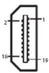
| Pin No. | Input signal |
| 1 | T.M.D.S Data 2+ |
| 2 | T.M.D.S Data 2 shield |
| 3 | T.M.D.S Data 2- |
| 4 | T.M.D.S Data 1+ |
| 5 | T.M.D.S Data 1 shield |
| 6 | T.M.D.S Data 1- |
| 7 | T.M.D.S Data 0+ |
| Pin No. | Input signal |
| 8 | T.M.D.S Data 0 shield |
| 9 | T.M.D.S Data 0- |
| 10 | T.M.D.S Clock+ |
| 11 | T.M.D.S Clock shield |
| 12 | T.M.D.S Clock- |
| 13 | Spare (not connected) |
| 14 | Spare (not connected) |
| Pin No. | Input signal |
| 15 | SCL |
| 16 | SDA |
| 17 | DDC/CEC GND |
| 18 | +5 V Power |
| 19 | Hot Plug Detect |
Specification of the mini D-SUB15pin terminal
Connect it to the mini D-SUB15pin output terminal of a video device.
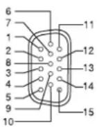
| Pin No. | Input signal |
| 1 | Red video signal |
| 2 | Green video signal |
| 3 | Blue video signal |
| 4 | Not connected |
| 5 | Ground |
| 6 | Red video signal return |
| Pin No. | Input signal |
| 7 | Green video signal return |
| 8 | Blue video signal return |
| 9 | Not connected |
| 10 | Ground |
| 11 | Not connected |
| 12 | I2C data |
| Pin No. | Input signal |
| 13 | Horizontal synchronization signal |
| 14 | Vertical synchronization signal |
| 15 | I2C clock |
Notice on transportation
This monitor is precision equipment and needs dedicated packing material for transportation. Never use any packing material supplied from sources other than JVC or JVC-authorized dealers.
- For easy understanding, pictures and illustrations are shown by being emphasized, omitted or composed, and may be slightly different from actual products.
- Design and specifications are subject to change without notice.
- All company names and product names mentioned herein are used for identification purposes only, and may be the trademarks or registered trademarks of their respective companies.
This model is manufactured, warranted and supported by SWIT Electronics Co., Ltd. / SWIT Electronics USA, LLC, and distributed in North America by JVCKENWOOD USA Corporation.
To obtain service or for further information, please contact:
Address: 3350 Scott Blvd. 61-02, Santa Clara, CA 95054
Toll free: 1 866 986-SWIT (7948) • Tel: 408 260-8258 • Fax: 408 228-8438
Email: info@swit.us • Website: www.swit.us
ProHD
SWIT Electronics Co., Ltd.
10 Hengtong Road, Nanjing Economic and Technological Development Zone
Nanjing 210038, P.R.China
Tel: +86-25-85805753 Fax: +86-25-85805296 Email: contact@swit.cc
www.swit.cc
- MULTI FORMAT LCD MONITOR
- DT-N24F
- INSTRUCTIONS
- CAUTION
- RISK OF ELECTRICAL SHOCK DO NOT OPEN
- IMPORTANT SAFEGUARDS
- POWER CONNECTION
- Under the following conditions,
- Safety Precautions (cont.)
- IMPORTANT SAFETY INSTRUCTIONS
- Operating Precautions
- Maintenance
- Unplug this product from the wall outlet before cleaning.
- LCD panel
- Cabinet
- Ventilation openings
- Installation
- Rear panel
- Note for connections
- Front panel
- Volume Adjustment
- On the Information Display
- Time code (SDI)
- UMD
- AFD (SDI)
- Audio Bar
- Histogram
- Vector
- Waveform
- On the Status Display
- The Operation Procedure
- Notice:
- Menu Transition Diagram
- Main Menu
- Picture Function
- Color Temperature
- Function Key
- GPI
- Menu Configuration (cont.)
- UMD
- - UMD setup
- Marker
- Audio Setting
- Vector
- Waveform
- Display
- System
- \*4, \*5 Update Driver/ Kernel
- Operation steps:
- OSD
- Key Inhibit
- About the external control
- Using the UMD control
- Using the GPI control
- To assign the functions to the pin terminals
- Operation of the external control
- The following are not malfunctions.
- Dimensions
- Available signals
- Specifications (cont.)
- Computer signals (preset)
- Specification of the HDMI terminal
- Specification of the mini D-SUB15pin terminal
- Notice on transportation
- ProHD
Brand : JVC
Model : DT-N24F
Category : Pregnant