VM-1010 - Lamp Bolt - Free user manual and instructions
Find the device manual for free VM-1010 Bolt in PDF.


| Product Type | Wireless TTL Macro Flash Set (includes VM-1010 flashes and VM-1020 transceiver) |
| Model | VM-1010 (Macro Flash), VM-1020 (Transceiver) |
| Brand | Bolt |
| Category | Photography Flash/Light |
| Guide Number (VM-1010) | 10 (ISO 100, meters) / 14 (ISO 200, meters) |
| Wireless Frequency | 2.4 GHz |
| Wireless Distance (VM-1010) | Up to 328 ft (100 m) |
| Number of Groups | 3 (A, B, C) |
| Number of Channels (VM-1010) | 4 |
| Number of Channels (VM-1020) | 16 |
| Flash Modes | TTL/Macro, S1/S2 Optical Slave, Manual |
| Transceiver Modes | Group, TTL Ratio, Multi (Canon only), Slave |
| Flash Compensation | TTL ±3 EV in 1/3 steps; Manual 1/128 to 1/1 in 1/3 steps |
| Recycle Time (VM-1010) | Approx. 4 seconds at full power |
| LED Focus Assist Light | Yes, adjustable power (VM-1020) and on flash units |
| LED Light (VM-1010) | 0.5 W, 5500K ±200K, CRI 90 |
| Battery Type (VM-1010) | 2× AAA (Alkaline recommended) |
| Battery Type (VM-1020) | 2× AA (Alkaline recommended) |
| Dimensions (VM-1010) | 2.8 × 3 × 2.4 in (7.1 × 7.8 × 6 cm) |
| Weight (VM-1010) | 3.7 oz (105 g) |
| Dimensions (VM-1020) | 2.1 × 2.5 × 3.3 in (5.4 × 6.3 × 8.4 cm) |
| Weight (VM-1020) | 3.8 oz (107 g) |
| Included Accessories | 2× VM-1010 flashes, 1× VM-1020 transceiver, flash mounting ring, mini-stand, 2× flash stands, 2× shoe adapters, 2× soft diffusers, 2× diffusers, 9 color gels per flash, gel pouches, padded case, lens adapters (52, 55, 58, 62, 67, 72, 77 mm) |
| Operating Temperature (VM-1010) | 10°F to 122°F (-10°C to 50°C) |
| Safety Features | Overheat protection, low battery indication, auto sleep after 90 seconds (transceiver) |
Frequently Asked Questions - VM-1010 Bolt
User questions about VM-1010 Bolt
0 question about this device. Answer the ones you know or ask your own.
Ask a new question about this device
Download the instructions for your Lamp in PDF format for free! Find your manual VM-1010 - Bolt and take your electronic device back in hand. On this page are published all the documents necessary for the use of your device. VM-1010 by Bolt.
USER MANUAL VM-1010 Bolt
natural_image
Black DSLR camera with extended lens and flash unit against a solid background (no visible text or symbols)VM-1000
TTL MACRO FLASH SET
User Manual
Thank you for choosing Bolt.
The Bolt VM-1000 is a full-featured wireless macro flash for your Nikon, Canon, or Sony camera. This advanced digital flash system puts creative control in your hands with a broad range of automatic and manual features. It can be used to illuminate close-up subjects with multi-flash setups and flexible wireless communication.
Enjoy automatic TTL settings with the ability to use up to three groups and sixteen channels without interference. Change auto flash compensation values or set flash power manually. With the included Macro Flash Ring, you can use up to four VM-1010 flash units. You'll be able to experiment with light and customize lighting settings to illuminate close-up subjects.
Table of Contents
Precautions 3
Contents 5
Overview 6
Battery Installation 12
Transceiver and Flash Setup 14
VM-1010 Flash Settings and Controls......20
VM-1020 Transceiver Settings and Controls .....22
Specifications....32
Troubleshooting 34
Firmware Upgrade ....35
FCC Compliance....35
Precautions

- Before using this product, please thoroughly read the following safety notices to ensure safe use and help prevent damage to your flash or injury to yourself and others.
- Do not fire the flash at close range directly into the eyes of people or animals. This can cause damage to the retina and may even lead to blindness.
- To avoid overheating and damaging your flash unit, please wait for at least ten minutes after twenty-five continuous flashes at full power.
-
Do not disassemble or attempt to repair this product yourself. There are high-voltage components inside that can produce a hazardous electric shock.
-
Keep this product and its batteries out of the reach of children.
- Use only the power sources specified in this manual.
• Always switch the flash off before changing the batteries. - Always install batteries of the same type, brand, and age. Do not combine different types or brands, or old and new batteries. This can cause the batteries to leak, overheat, or explode. Install the batteries in the proper orientation, according to the indicator in the battery chamber. Installing batteries in the reverse orientation may cause them to leak, overheat, or explode.
-
Do not clean this product with agents containing corrosive or flammable substances such as paint thinner, benzene, or nail-polish remover.
-
Do not use or store this product in flammable conditions (such as environments containing flammable gases or liquid chemicals). This can damage the flash, start a fire, or cause an electric shock.
- This product is not water resistant. Keep it away from rain, snow, humidity, and general moisture.
- If you detect a burning smell, smoke, or excessive heat coming from the flash, immediately stop operation and remove the batteries to prevent the product from igniting or melting.
-
Do not drop or otherwise cause a strong physical impact to this product, as this can cause a malfunction that may cause it to explode or ignite.
-
Should the product sustain physical damage, do not touch any exposed interior metal parts. If touched, they may generate an electric shock or cause a malfunction. Promptly remove the batteries, and take the product to an authorized service center for repair.
- For long-term storage, remove all batteries from this product to prevent the product from igniting or leaking corrosive liquids.
- Do not store or use this product at temperatures above 149^ (65°C).
Contents
- Keep the metal contacts in the battery compartment clean and free of corrosion and dirt. Do not touch them with your fingers. Corrosive elements on the contacts can damage this product and prevent it from functioning properly. Contacts may be cleaned with isopropyl alcohol on a cotton swab.
- Dispose of used batteries properly. Never heat them or throw them into a fire, as this can cause the batteries to leak corrosive liquids, generate heat, or explode.
- Images are for illustrative purposes only.
• VM-1010 TTL Macro Flash (×2)
• VM-1020 TTL Transceiver
- Flash mounting ring
• Transceiver mini stand
- Macro Flash stand (×2)
- Shoe adapters (×2)
- Soft diffuser (×2)
- Diffuser (×2)
- 9 color gels (×2)
- Gel pouch (x2)
- Padded zippered case
- Lens adapters: 52, 55, 58, 62, 67, 72, and 77 ~mm
Overview
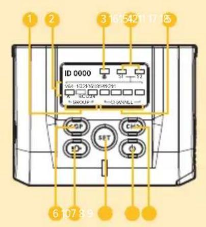
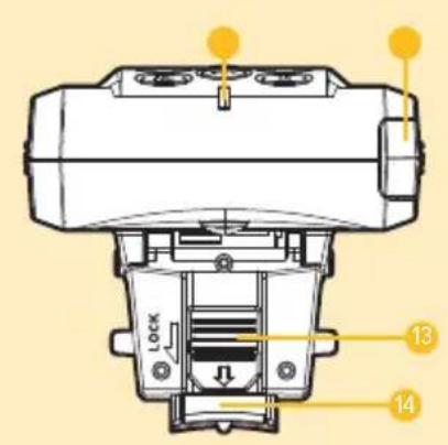
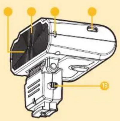
Macro Flash VM-1010
1 Group LED indicators
2 Luminance LED indicators
3 Macro TTL LED indicator
4 S1/S2 LED indicators
5 Channel LED indicators
6 Group / < button
7 LED focus assist light / flash test button
8 Set button
9 Power button
10 Channel / > button
11 LED status indicator
12 Battery cover
13 Mounting-foot lock
14 Mounting foot
15 Flash sensor
16 LED assist lamps
17 Diffuser notches
18 USB interface
19 Slide release
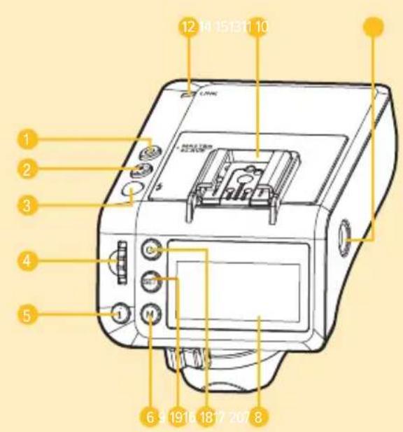
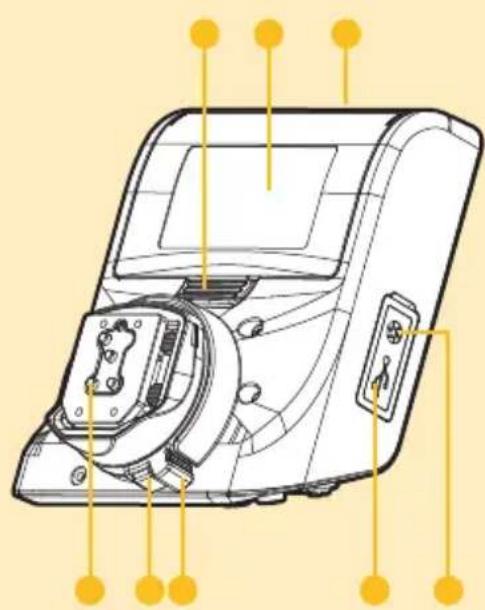
Transceiver VM-1020
1 Power button
2 LED focus assist button
3 Flash test LED indicator/button
4 Adjustment dial
5 Info button
6 Mode button
7 Set button
8 Group button
9 LCD
10 1/4-20 socket
11 Hot shoe
12 Link indicator LED
13 Battery compartment button
14 Battery compartment door
15 LED focus assist
16 Mounting foot
17 Collar-lock release button
18 Foot-collar lock
19 USB port
20 2.5 mm shutter-release sync port
natural_image
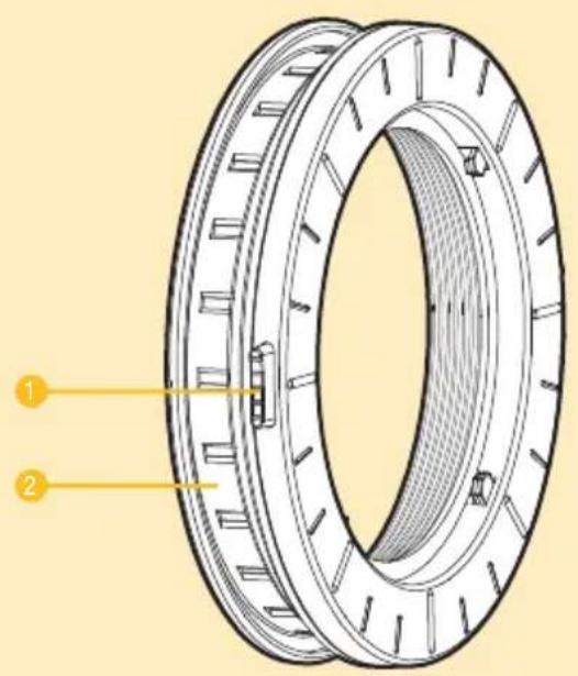
Line drawing of a device with labeled ports and connectors (no text or symbols)Flash Mounting Ring
1 Ring release button ( × 2)
2 Flash holder ring
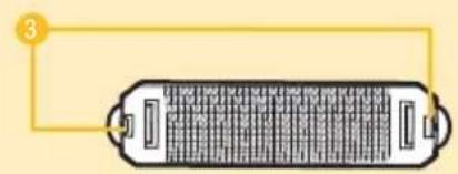
Diffuser
3 Notch windows
Shoe Adapter
4 Foot mount
5 Locking wheel
6 Mounting foot
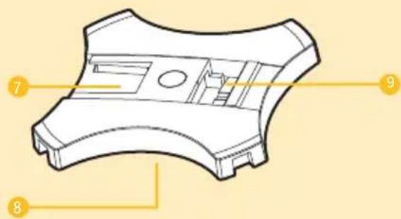
Flash Stand
7 Cold shoe
8 1/4-20 socket
9 Foot mount
natural_image
Diagram of a battery pack with labeled connection point (no text or symbols on the main body)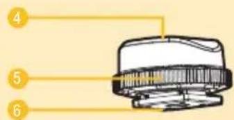
Battery Installation
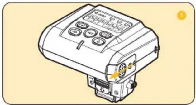
VM-1010
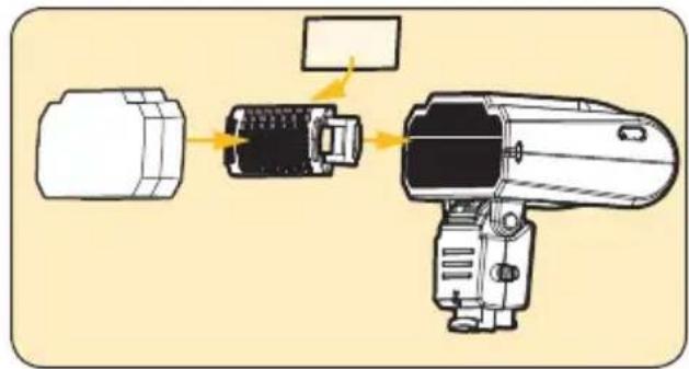
- Push and slide out the battery compartment door in the direction of the arrow.
- Insert the batteries with the correct polarity orientation.
- Slide the battery door closed until it's secure.
natural_image
Line drawing of a mechanical device with control buttons and a yellow indicator light (no text or symbols)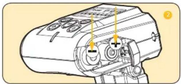
natural_image
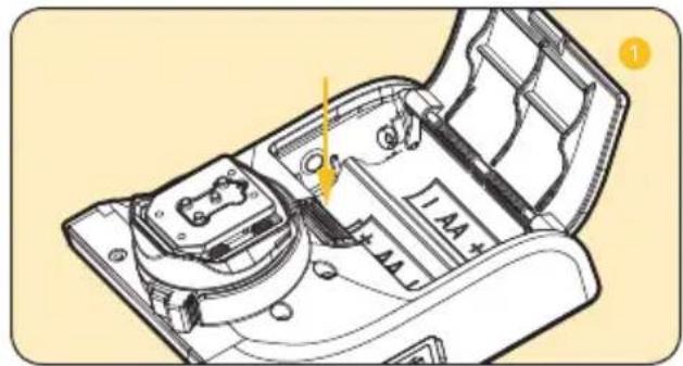
Technical line drawing of a mechanical device with no visible text or symbolsVM-1020
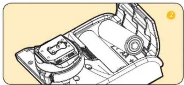
- Press the battery compartment button to open the door.
- Insert the batteries on top of the release pull, with the correct polarity as shown inside the compartment.
- Close the compartment door until secure.
Note: When the batteries are low on power, the battery icon will blink. If the batteries are out of power, the screen displays NO POWER, and the unit will turn off.
natural_image
Technical line drawing of a mechanical assembly with no visible text or symbolsTransceiver and Flash Setup
Mounting the Transceiver to a Camera
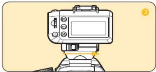
- Press the collar-lock release button, and slide the collar to the left to unlock.
- Insert the mounting foot into your camera's hot shoe.
- Slide the collar to the right until it clicks and is locked.
Mounting the Transceiver to a Stand
Mini Stand
- Make sure the transceiver's collar lock is in the unlocked position.
- Slide the transceiver into the mini-stand's cold shoe, and slide the collar to the right until it locks.
natural_image
Illustration of a camera with adjustment knobs and a screen, no text or symbols present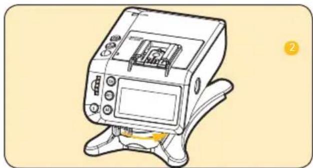
natural_image
Line drawing of a medical device with control panel and display screen (no text or symbols)Light Stand
You can mount the transceiver to a light stand, using the mini-stand or transceiver's 1/4-20 socket.
- Screw the mini stand on to a light stand using the 1/4-20 mount.
- Attach the transceiver to the mini-stand's cold shoe, and slide the collar lock to the right until secure.
Alternatively, you can screw the transceiver's 1/4-20 socket to a wide variety of grips and mounting hardware.
Mounting a Flash to the Transceiver
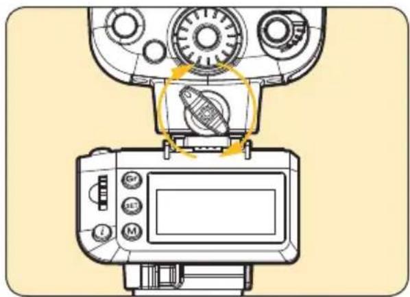
A flash can mount to the transceiver and operate remotely with TTL functionality, as if mounted directly to your camera.
Mounting the Macro Flash
Setting Up the Flash Mounting Ring
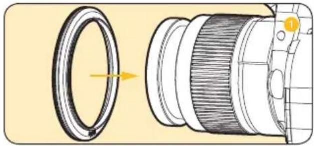
- Choose the lens adapter (52, 55, 58, 62, 67, 72, or 77 ~mm ) that fits your lens, and screw it onto the lens's filter threads.
- Squeeze the ring release buttons, seat the flash mounting ring over the lens adapter, and release. Wiggle the mounting ring a little to make sure it's secure.
natural_image
Technical illustration of a camera lens assembly showing the aperture and main frame (no text or symbols)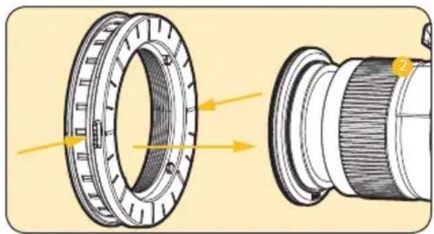
natural_image
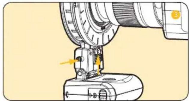
Technical illustration of a mechanical component with cross-sectional view and labeled parts (no text or symbols present)- Seat the flash's mounting foot into the ring's flash holder, and slide the foot lock down to secure. Use the slide release buttons to adjust the flash's postion around the ring.
natural_image
Technical illustration of a mechanical assembly with a component and directional arrow (no text or symbols)Mounting the Flash to the Flash Stand
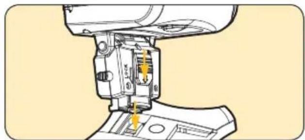
- Hook the flash's mounting foot into the stand, and seat the foot into the flash stand.
- Slide the lock down to secure.
natural_image
Technical illustration of a sewing machine needle insertion into a base (no text or symbols visible)Using the Shoe Adapter
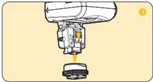
- Hook the flash's mounting foot into the shoe adapter's foot mount.
- Slide the lock down to secure.
- Slide the shoe adapter's foot into the cold shoe of the flash stand.
- Rotate the locking wheel clockwise until secure.
Adjusting the Flash Angle
You can adjust the flash head to angles of -45^ to 60^ .
natural_image
Diagram of a mechanical assembly with a component inserted into a housing (no text or symbols visible)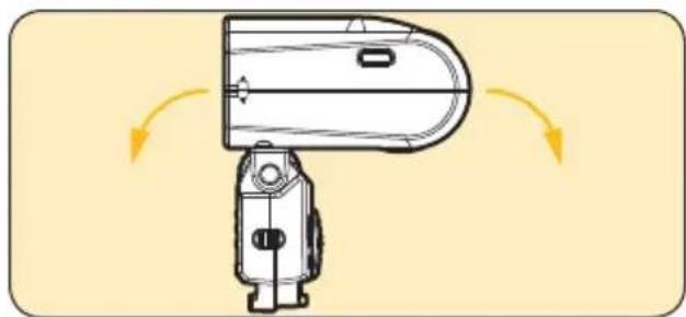
natural_image
Diagram of a handheld device with directional arrows indicating motion or rotation (no text or symbols)Attaching a Diffuser
Diffuser
Attach the diffuser over the diffuser notches. Make sure they line up with the diffuser notch windows.
Soft Diffuser
You can attach the soft diffuser over the diffuser or directly to the flash head. Make sure the soft diffuser is in the correct orientation.
natural_image
Diagram of a mechanical device with exploded view showing internal components and assembly (no text or labels)Using the Gels
A collection of nine color gels are included with each flash, so you can change the flash color temperature.
- Insert a gel inside the diffuser.
- Attach the diffuser to the front of the flash.
VM-1010 Flash Settings and Controls
TTL/Macro Mode
Press and hold the power button [©] to turn the flash on. LED indicators will light up for TTL/Macro mode, Group A, and Channel 1.
To cycle through groups A, B, and C, press Group [◀] To cycle through channels 1, 2, 3, and 4, press Channel [◀].
Note: When using the flashes with the transceiver, you must make sure to set them all to the same channel and group.
S1/S2 Slave Modes
In the S1/S2 Slave modes, the VM-1010 is set to be optically triggered by an external flash source. The S1 mode fires on any flash, while the S2 mode ignores the preflash and fires on the second flash. You will set the flash power manually when using these modes.
- Press the Set button [] to switch to the S1 or S2 mode.
- Press [] or [] buttons to increase or decrease the flash output power.
LED Focus Assist/Flash Test
Press the LED Focus Assist/Flash Test [button to fire off a test flash.
Press and hold the LED Focus Assist/Flash Test [button to enable and disable the LED Focus Assist lights.
VM-1020 Transceiver Settings and Controls
Press and hold the power button [¢] until the Flash Test button lights up, and the LCD displays the flash settings. Any changes to the settings will be saved after eight seconds of inactivity. Pressing the Info [☐] and Mode [M] buttons at the same time will reset all setting and parameter changes.
Group Mode
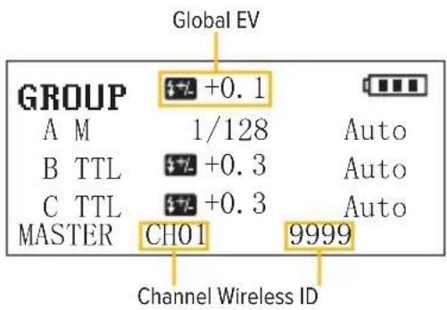
Group mode allows you to use automatic TTL settings or have manual control over groups A/B/C. Set flash power, focal distance, or overall group compensation. There are three flash modes per group: TTL, M, or Off. TTL uses automatic settings from the camera with user control over flash compensation. Manual allows you to set the flash power of the group. Off will disable a group.
Group Mode Zoom
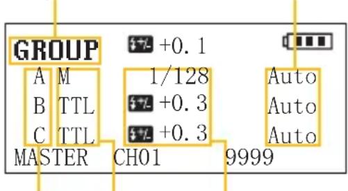
Flash Groups Flash Modes Flash Adjustments
- Press the Mode [] button to switch to Group mode.
- Press the Group [Gr] button to highlight and enter group selection, and use the Adjustment dial to select the groups A/B/C. Make sure the VM-1010 flashes are set to the same group.
- Press the Set [SET] button once to select the group flash mode. Use the adjustment dial to select TTL, M, or Off.
- Press the Set [SET] button again to change the flash compensation or power. Use the adjustment dial to adjust negative (-) or positive (+) compensation or power values.
- Press the Set [SET] button again to adjust the zoom focus parameter. Use the adjustment dial to set zoom focus to Auto or manually adjust between 18 and 200 mm.
- Press the Set [] button again to confirm the group settings.
Setting the Wireless Channel
- Press the Info [] button once, and the wireless channel will blink. Use the adjustment dial to change the channel from 1 to 16.
- Press the Set [] button to confirm.
Keep in mind the VM-1010 macro flashes operate on channels 1 to 4, and the transceiver must be set to one of the corresponding channels.
Setting the Wireless ID
The wireless ID must be set to 0000 to use with the VM-1010 Macro Flashes.
- Press the Info [i] button twice until the first 0 of the ID is blinking. Use the adjustment dial to change values.
- Press the Info [i] button again for each additional digit of the ID, and use the adjustment dial to change the value.
- Press the Set [] button to confirm.
Global EV Compensation
The global EV compensation allows you to apply the same exposure value adjustment to all groups, independent of the flash power set for each one.
Press the Info [ ] button until global EV is blinking, and use the adjustment dial to change the value. Press the Set [ ] button to confirm.
Multi Mode (Canon Only)
Multi mode fires the flash repeatedly during a single exposure, creating a multi-exposure effect. Use this feature to capture stroboscopic photos of a dancer leaping across a stage or a golfer swinging a driver. To use Multi mode, you'll need a second VM-1020 transceiver along with a Canon Speedlite.
Multi Mode
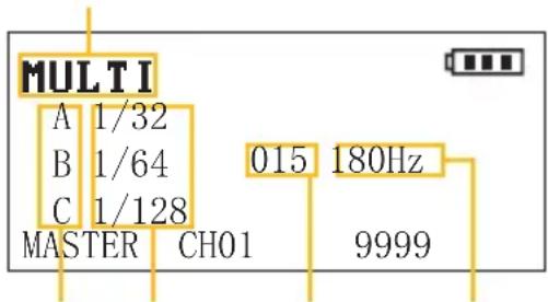
Flash Groups Flash Power Frequency# of Flashes
- Press the Mode [ ] button to switch to Multi mode.
-
Press the Group [Gr] button to highlight and enter group selection, and use the Adjustment dial to select the groups A/B/C.
-
Press the Set [SET] button to highlight and change the flash group's power. Use the Adjustment dial to select the power level in six steps from 1/4 to 1/128.
- Press the Info [i] button until the number of shots is flashing. Use the Adjustment dial to select the number of shots from 0 to 90 (selection is based on the camera's shutter speed).
- Press the Info [i] button until the frequency of shots is flashing. Use the Adjustment dial to select the frequency from 1 to 199 Hz.
- Press the Set [] button to confirm the settings.
- Mount your Canon Speedlite on a second VM-1020 transceiver, and set the transceiver to Slave mode (see Slave Mode below). Make sure both transceivers are set to the same channel and the slave is set to the desired group.
TTL Ratio Mode
This mode allows you to set power ratios between groups A and B. Group C works independently and offers TTL, manual, or off modes. For example, if you set a ratio of 1:2 between groups A and B, group B will fire with two times more power than group A.
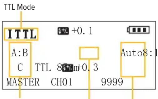
Flash Groups Flash Group Ratios Zoom
- Press the Mode [] button to switch to TTL mode.
- Press the Group [Gr] button to highlight and enter group selection, and use the adjustment dial to select groups A:B or C.
- When A:B is selected, press the Set [SET] button once to select the group flash ratios. Use the adjustment dial to select a ratio from 8:1 to 1:8.
-
Press the Set [SET] button again to adjust the zoom focus parameter. Use the adjustment dial to set the zoom focus.
-
Press the Set [] button again to confirm the group A:B settings.
You can change Group C settings according to the instructions in Group Mode above.
To set the wireless channel and ID number, as well as the overall group compensation, see Setting the Wireless Channel, Setting the Wireless ID, and Global EV Compensation above.
Slave Mode
In this mode, the transceiver acts a slave, and it receives flash information from the master unit. Use this mode when you need to wirelessly trigger a speedlight or camera.
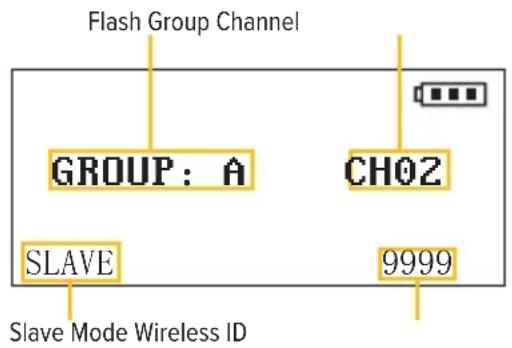
- With the unit powered on, press the power [] button once to enter Slave mode.
- Press the Group [] button to cycle through groups A/B/C.
- Press the Info [i] button to change the wireless channel and ID (see Setting the Wireless Channel and Setting the Wireless ID above).
LED Focus Assist
Press the LED Focus Assist [button to turn on the transceiver's LED focus assist light. Use the adjustment dial to change the power level. Press and hold the [button to turn on the LED Focus Assist Light for the VM-1010 flashes.
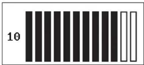
LED Focus Assist Power Level
Flash Test
Press the Flash Test [button to fire off a test flash from all the flashes in your setup. This ensures everything is linked correctly.
Triggering a Studio Light
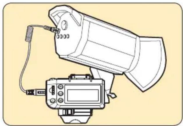
You can wirelessly trigger a studio light using the VM-1020's 2.5 mm sync port and the master/slave setup between multiple transceivers.
Sleep Mode
When the VM-1020 is idle for ninety seconds, the unit will enter sleep mode. Press any button to wake the VM-1020.
natural_image
Line drawing of a camera with attached display and cable (no text or symbols)Specifications
Transceiver (VM-1020)
Operating Frequency: 2.4 GHz
Operating Distance: 98 ft. (30 m)
Groups: 3
Channels: 16
Battery Type: AA
High-Speed Sync: 1/8000
LED Light Output: 5500 K ±200 K, Ra 90
LED Focus Assist Output: 1.2 to 2 W
Manual Output: 1/128 to 1/1 in 1/3 increments
TTL Output: ±3 in 1/3 increments
Antenna: Built-in PCB
Output Ports: 2.5 mm
Input Ports: USB
Input Voltage: n/a
Operating Temperature: 5°F to 149°F (-15°C to 65°C)
Storage Temperature: -22°F to 185°F (-30°C to 85°C)
Dimensions ( H × W × D ): 2.1 × 2.5 × 3.3 in.
(5.4 × 6.3 × 8.4 cm)
Weight: 3.8 oz. (107 g)
Macro Flash (VM-1010)
Guide Number: 10 (ISO 100 m) / 14 (ISO 200 m)
LED Light: 0.5 W, 5500 K ±200 K, RA 90
Groups: 3
Channels: 4
S1/S2 Distance: Indoor: 65.6 ft. (20 m) Outdoor: 32.8 ft. (10 m)
Wireless Frequency: 2.4 GHz
Wireless Distance: 328 ft. (100 m)
Cover Angle: -45^ to 60^
Recycle Time: 4 sec. at 1/1 output
Battery Type: AAA
Operating Temperature: 10°F to 122°F
(-10°C to 50°C)
Storage Temperature: -4°F to 158°F (-20°C to 70°C)
Dimensions (H × W × D): 2.8 × 3 × 2.4 in.
(7.1 × 7.8 × 6 cm)
Weight: 3.7 oz. (105 g)
Troubleshooting
| Problem Solution | |
| The VM-1000 does not turn on. | Replace the batteries. (Note: If the batteries are low, replace both batteries at the same time. Do not use different brands or types of batteries.)Make sure that the batteries are inserted into the battery compartment with the correct polarity orientation. |
| The slave units do not fire. | Make sure that all VM-1010 and VM-1020 units are set to the same channel and group. Make sure channel ID numbers are set appropriately. The default value for normal operation is 0000.Make sure all devices are powered on.Check the contact between the flash's mounting foot and each hot shoe. Also check the hot-shoe connection between the camera and the transceiver. Make sure all mounting feet have been fully inserted into the corresponding hot shoes. Make sure each VM-1020 is operating in the correct Master or Slave mode. |
| The picture is underexposed or overexposed. | If the subject looks too dark or light, change the exposure compensation value (EV).If your camera is in HSS mode, the effective flash range is shorter. Position the light closer to the subject. |
Firmware Upgrade FCC Compliance
Visit www.boltflashes.com for more information on the latest firmware version.
Connect the VM-1010's and VM-1020's USB ports to a computer, and follow the instructions for downloading and installing the latest firmware version.
This device complies with Part 15 of the FCC Rules. Operation is subject to the following two conditions:
- This device may not cause harmful interference.
- This device must accept any interference received, including interference that may cause undesired operation.
One-Year Limited Warranty
This BOLT product is warranted to the original purchaser to be free from defects in materials and workmanship under normal consumer use for a period of one (1) year from the original purchase date or thirty (30) days after replacement, whichever occurs later. The warranty provider's responsibility with respect to this limited warranty shall be limited solely to repair or replacement, at the provider's discretion, of any product that fails during normal use of this product in its intended manner and in its intended environment. Inoperability of the product or part(s) shall be determined by the warranty provider. If the product has been discontinued, the warranty provider reserves the right to replace it with a model of equivalent quality and function.
This warranty does not cover damage or defect caused by misuse, neglect, accident, alteration, abuse, improper installation or maintenance. EXCEPT AS PROVIDED HEREIN, THE WARRANTY PROVIDER MAKES NEITHER ANY EXPRESS WARRANTIES NOR ANY IMPLIED WARRANTIES, INCLUDING BUT NOT LIMITED TO ANY IMPLIED WARRANTY OF MERCHANTABILITY OR FITNESS FOR A PARTICULAR PURPOSE. This warranty provides you with specific legal rights, and you may also have additional rights that vary from state to state.
To obtain warranty coverage, contact the BOLT Customer Service Department to obtain a return merchandise authorization ("RMA") number, and return the defective product to BOLT along with the RMA number and proof of purchase. Shipment of the defective product is at the purchaser's own risk and expense.
For more information or to arrange service, visit www.boltflashes.com or call Customer Service at 212-594-2353.
Product warranty provided by the Gradus Group.
www.gradusgroup.com
BOLT is a registered trademark of the Gradus Group.
© 2019 Gradus Group LLC. All Rights Reserved.

BOLT*
A Gradus Group Brand
- TTL MACRO FLASH SET
- Thank you for choosing Bolt.
- Table of Contents
- Precautions
- Contents
- Overview
- Macro Flash VM-1010
- Transceiver VM-1020
- Flash Mounting Ring
- Diffuser
- Shoe Adapter
- Flash Stand
- Battery Installation
- VM-1010
- VM-1020
- Transceiver and Flash Setup
- Mounting the Transceiver to a Camera
- Mounting the Transceiver to a Stand
- Mini Stand
- Light Stand
- Mounting a Flash to the Transceiver
- Mounting the Macro Flash
- Setting Up the Flash Mounting Ring
- Mounting the Flash to the Flash Stand
- Using the Shoe Adapter
- Adjusting the Flash Angle
- Attaching a Diffuser
- Soft Diffuser
- Using the Gels
- VM-1010 Flash Settings and Controls
- TTL/Macro Mode
- S1/S2 Slave Modes
- LED Focus Assist/Flash Test
- VM-1020 Transceiver Settings and Controls
- Group Mode
- Setting the Wireless Channel
- Setting the Wireless ID
- Global EV Compensation
- Multi Mode (Canon Only)
- TTL Ratio Mode
- Slave Mode
- LED Focus Assist
- Flash Test
- Triggering a Studio Light
- Sleep Mode
- Specifications
- Transceiver (VM-1020)
- Macro Flash (VM-1010)
- Firmware Upgrade FCC Compliance
- One-Year Limited Warranty
Brand : Bolt
Model : VM-1010
Category : Lamp