FreeWave Aviator - Remote control Vello - Free user manual and instructions
Find the device manual for free FreeWave Aviator Vello in PDF.

User questions about FreeWave Aviator Vello
0 question about this device. Answer the ones you know or ask your own.
Ask a new question about this device
Download the instructions for your Remote control in PDF format for free! Find your manual FreeWave Aviator - Vello and take your electronic device back in hand. On this page are published all the documents necessary for the use of your device. FreeWave Aviator by Vello.
USER MANUAL FreeWave Aviator Vello
Thank you for choosing the Vello FreeWave Aviator System. The FreeWave Aviator is a professional solution for wirelessly controlling off-camera TTL-capable flashes while retaining full TTL capability. The FreeWave Aviator System is an ideal tool for photographers on every level. The Aviator gives you the ability to fine tune your lighting and help you match your final shot to your creative vision.
The Vello FreeWave Aviator allows for an impressive range of wireless control. Supporting up to 16 channels, flashes can be arranged in three groups, which can each be set to TTL or Manual mode. The TTL EV compensation, manual power, and zoom levels for each group can be
changed separately, and groups can also be controlled with ratio-based adjustments. This allows the flexibility to be creative with different lighting treatments and effects. You can instantly raise and lower power levels on select lights, or use the zoom control to change the tone and shape of the lighting for exciting new looks.
With its multiple groups feature, you can easily configure up to three different light groups, which can be triggered individually or simultaneously, for a total of seven different combinations. (Simultaneous triggering of multiple flash groups requires additional FreeWave Aviator Receivers or Transceivers, available separately.)
The FreeWave Aviator does not require line-of-sight positioning, since its radio waves pass through and around objects, such as walls, windows, and floors. It also functions in all lighting conditions including bright daylight or direct sunshine.

natural_image
Two black electronic devices with display screens, one showing a small circular icon and the other displaying a grid of connected ports (no visible text or symbols on device surfaces)TABLE OF CONTENTS
Contents 4
Key Features....5
Precautions....6
Overview 8
Before You Begin....10
Compatible Devices....10
Mounting/Turning on the Transceiver......11
Mounting the Receiver.... 12
Mounting a Hot-Shoe Flash to a
Receiver/Transceiver 13
Using Studio Flashes with a Receiver or Transceiver....14
About TTL....15
Setting Channels.... 16
Adjusting Master/Slave Mode on the Transceiver....17
Setting Flash Groups 18
Adjusting a Flash Group's TTL Power (EV)....20
Adjusting a Flash Group's Zoom....21
Using TTL Ratio Adjustment Modes......22
Changing a Flash Group's Power Mode.....24
Using High Speed Sync/Second Curtain Sync Modes....25
Setting Auto-Focus Assist (Nikon Only)......27
Additional Features 28
Resetting the Transceiver to Factory Default Settings....29
Specifications 30
Troubleshooting 31
FCC Compliance.... 31
CONTENTS
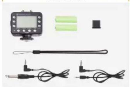
Transceiver
- Transceiver
• Lanyard
• 3.5 mm to 3.5 mm cable - 3.5 mm to 1/4" mono-plug cable
- Hot-shoe protector
- 2 × AA batteries
- User manual
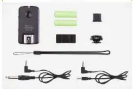
Receiver
- Receiver
• Lanyard
• 3.5 mm to 3.5 mm cable
• 3.5 mm to 1/4" Mono-plug cable
• Hot-shoe protector
• Adhesive backed accessory shoe - Hot-shoe locknut
- 2 × AA batteries
- User manual
Transceiver Kit
natural_image
Product photo of a handheld electronic device with two cables and a sensor, no visible text or symbolsReceiver Kit
natural_image
Product display of a handheld electronic device with various components and wires (no visible text or symbols)KEY FEATURES
Wireless TTL (Through-the-Lens):
makes full use of your flashes' built-in TTL technology
16 Channels (2.4 GHz Radio):
allow the setting of different channels to avoid interference
Three Flash Groups:
enable configuration of different flash groups with individual settings
Master/Slave Function: enables the
Transceiver to be used as either a Master (Transmitter) on your camera or as a Slave (Receiver) with a flash attached
TTL or Manual Mode: remotely
sets your flash to TTL or Manual mode and can adjust power levels
TTL Exposure Compensation: enables
fine tuning of TTL exposure by +/- 3 EV
High Speed Sync:
allows flash synchronization up to 1/8000 of a second
Regular or Second Curtain Sync:
allows you to create special effects and "after blur" images
Flash Zoom Control: remotely sets
the zoom on all compatible flashes
Additional Lighting Options:
can trigger Studio Lights together with your hot-shoe flashes
Backlit Digital Display: allows easy
viewing and changing of settings in all lighting conditions on the Transceiver
can be used for a more secure connection with a Receiver
TTL Hot Shoe: allows you to use a
TTL flash on-camera (pass through)
Battery Indicator: displays battery
life on the Transceiver
PRECAUTIONS
- Please read full manual before using device.
- Do not disassemble or modify. Failure to observe this precaution could result in electric shock or product malfunction. Should the product break open due to accidental damage, remove the batteries and send it to an authorized repair center.
-
Keep dry. Do not handle with wet hands, immerse in water, or expose to rain or snow. Failure to observe this precaution could result in fire or cause electric shock.
-
Do not use in the presence of flammable gases. Failure to observe this precaution could result in fire or explosion.
- Keep out of the reach of children. This product contains small parts that may pose a choking hazard. Should a child swallow any part of this product, consult a physician immediately.
-
Turn off immediately should a malfunction occur. Should smoke or any unusual smell come from this product, shut it off and remove the batteries immediately. Send it to an authorized repair facility for service. Continued use may result in damage or physical injury.
-
Do not expose to high temperature. Do not leave product in a closed vehicle in the sun or other area subject to extremely high temperature. Failure to observe this precaution could result in fire or damage to casing or internal parts.
- Observe precautions when handling batteries. Batteries may leak or explode if improperly handled. Please observe the following precautions when using batteries with this product.
-
Use only batteries listed in this manual. Do not mix new and old batteries or different brands or types of batteries.
-
Read and follow all warnings and instructions provided by the battery manufacturer.
- Do not attempt to short-circuit or disassemble batteries.
- Do not put batteries in a fire, or apply direct heat to them.
-
Do not attempt to install batteries in the reverse direction.
-
Batteries may leak when fully discharged. To avoid damage to the product, be sure to remove the batteries if the product will not be used for an extended period of time or if the battery power is low.
- Should fluid from damaged batteries come into contact with skin or clothing, rinse immediately with fresh water.
• Pictures are for illustration only.
OVERVIEW
Transceiver
- LCD Display Screen
- Group Settings Buttons (A,B, and C)
- LED Indicator
- Test Button
- Menu Button
- Option Button
- Flash Sync Mode Button
- Select Button
-
- and - Buttons
- TTL-Dedicated Hot Shoe
- Battery Compartment
- Locking Wheel
- Power Switch
- 3.5 mm Sync Output Port
- USB Port
Front Right

text_image
VCELLO Asiator A B C S S Test Main Option Max BP Select +LOCK ① ② ③ ④ ⑤ ⑥ ⑦ ⑧ ⑨ ⑩Back Left

text_image
VELLO FreeWave Ablator Wheels Roll Trigger TRANSCEIVER OECN 11 12
natural_image
Technical line drawing of a camera lens with adjustment knob and base mount (no text or symbols)
text_image
⑭ ⑮ ⑯ ⑰ ⑱ ⑲ ⑳ ⑴Receiver
- LED Indicator
- Test Button
- TTL-Dedicated Hot Shoe
- Battery Compartment
- 1/4"-20 Lightstand Socket
- Channel Switch
- Power Switch
- Threaded PC Sync Output Port
- Group Switch
- USB Port
- 3.5 mm Sync Output Port
- Lanyard Mount
Top Left

text_image
① ② ③ VELLO FreeNex Anterior Wireless Linker RECEIVER
text_image
⑥ ⑦ ⑧Bottom Right

text_image
④ ⑤ N=10
text_image
⑨ ⑩-12Front

natural_image
Simple line drawing of a battery with two terminals and internal components (no text or symbols)BEFORE YOU BEGIN
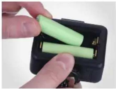
Installing the Batteries
The Aviator Transceiver and Receiver units each require two AA batteries to operate.
To install, open the battery compartment door and insert the batteries as indicated by the polarity icons in the compartment. Once installed, close the compartment door.
natural_image
Close-up of hands holding a black rectangular battery pack with two green batteries, no visible text or symbols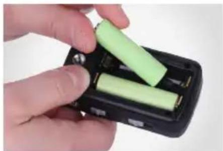
natural_image
Close-up of hands inserting a green cylindrical battery into a black plastic case (no text or symbols visible)COMPATIBLE DEVICES
The Vello FreeWave Aviator is available in models for both Nikon i-TTL and Canon E-TTL cameras. The Nikon and Canon models are each compatible with the respective company's TTL (Through-The-Lens) technology.
To make full use of the Aviator system, we recommend using TTL-capable hot-shoe flashes that are fully compatible with your camera's TTL system.
FreeWave Aviator Transceivers and Receivers do not provide high-voltage sync protection, and they are not recommended for use with flash units that have a trigger voltage of more than 6V.
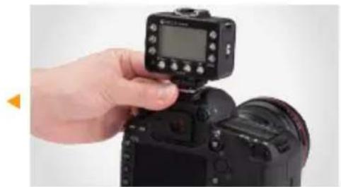
MOUNTING/TURNING ON THE TRANSCEIVER
- With your camera and Transceiver Off, loosen the Transceiver's locking ring.
- Insert the Transceiver's hot shoe on your camera's hot-shoe mount with the LCD panel facing the rear of the camera.
- Tighten the Transceiver's locking ring.
- Turn on the Camera and then slide the Transceiver's Power Switch to On.
- Slide to Off position to turn the Transceiver off.
natural_image
Hand holding a DSLR camera with a digital display on top (no visible text or symbols)
natural_image
Close-up of a hand pressing a black mechanical component on a device (no visible text or symbols)Note: make sure that your Master Transceiver and all Receiver units and Slaves are set to the same Channel before use.
Note: the Aviator Transceiver can also be mounted on any hot-shoe or cold-shoe compatible stand.
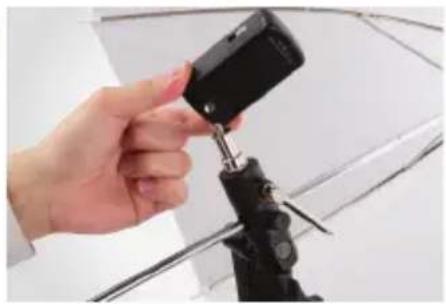
MOUNTING THE RECEIVER
- With your Receiver and flash Off, mount the Receiver to your 1/4"-20 light stand or accessory stand. Take care not to overtighten the Receiver.
- Slide the Group Switch to A, B, or C to select the desired Group. (The Group D setting on the Receiver is for factory calibration only and is not available for use.)
- Slide the Channel Switch to 1, 2, 3, or Auto. ("Auto" is equal to the Transceiver's Channel "4".)
natural_image
Hand holding a black camera module with a tool, mounted on a tripod (no visible text or symbols)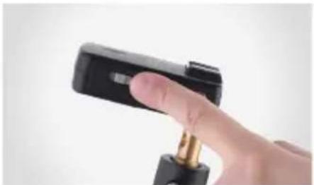
natural_image
Close-up of a hand holding a black handheld device with a gold connector (no visible text or symbols)Note: make sure that all your FreeWave Aviator units are set to the same channel before use.
MOUNTING A HOT-SHOE FLASH TO A RECEIVER/TRANSCEIVER
- Make sure the flash and Receiver or Transceiver are turned Off.
- Switch the flash's locking switch to the unlocked position.
- Insert the flash's hot-shoe foot into the Receiver or Transceiver's hot-shoe mount.
- Switch the flash's locking switch to the locked position.

natural_image
Hand holding a black DSLR camera on a tripod, with a white umbrella in the background (no text or symbols visible)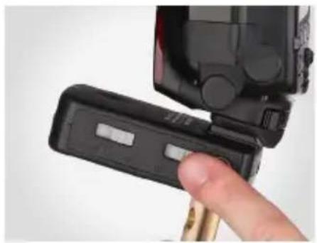
natural_image
Close-up of a hand inserting a black plastic device into a black plastic housing (no visible text or symbols)- Turn on the flash.
- Your flash must be in TTL mode in order to function properly in all modes with the FreeWave Aviator. (See your flash's manual for assistance.)
- Turn on your Aviator Receiver or Transceiver by moving the switch to the On position.
USING STUDIO FLASHES WITH A RECEIVER OR TRANSCEIVER
For more complex lighting needs, the FreeWave Aviator can also trigger studio flashes independently or alongside hot-shoe flashes. (Note that TTL compatibility is only available for TTL-capable flashes.)
Both the Aviator Receiver and Transceiver have 3.5 mm Sync Ports, and the Receiver also has a PC Sync Port which allows you to connect a sync cable to your studio flashes.
Note: the PC Sync Port will also accept a PC locking cable.
Connecting with a 3.5 mm Cable
- Plug the 3.5 mm cable into the Receiver or Transceiver's Sync Port.
- Plug the other end of the cable into the studio flash's 3.5 mm jack.
- If your studio flash has a 1/4" monoplug jack, you will need to use the included 3.5 mm to 1/4" monoplug cable.
Connecting with a PC Sync Cable
- Using a PC Sync to 3.5 mm cable (not included), plug the PC Sync end into the Receiver's PC Sync port.
- Plug the 3.5 mm end of the cable into the studio flash's 3.5 mm jack.
- If your studio flash has a 1/4" monoplug jack, you will need to use a PC Sync to 1/4" monoplug cable (not included).

natural_image
Close-up of a hand holding a small electronic device with a key inserted (no visible text or symbols)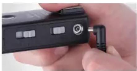
natural_image
Close-up of a hand holding a black electronic device with a metallic connector (no visible text or symbols)ABOUT TTL
The FreeWave Aviator automatically sets the appropriate flash level using your camera's through-the-lens (TTL) metering system data, calculating the correct power for all communicating TTL compatible flashes.
text_image
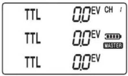
TTL 0.0EV CH / TTL 0.0EV MASTER TTL 0.0EVMain TTL Adjustment Screen
The startup or default screen for the Aviator Transceiver is called the TTL Screen. Many of the instructions start out from the TTL Screen, so it will be helpful to remember how to return to it.
To return to the TTL Screen while in Master mode (see page 17), simply press the Option button once or twice until the screen appears. (If the device is in Slave mode, you will first have to return to Master mode.)
Once set, the Aviator Transceiver retains all changes made to its settings, even after the device is turned off.
Note: see page 29 for resetting the Transceiver to factory default settings.
SETTING CHANNELS
Setting an Aviator
Transceiver's Channel
To set the desired Channel, do the following:
- From the TTL Screen or the Slave Mode screen, press Menu to enter Channel Select.
- Use the + and - buttons to select the desired channel from 1-16 (channels 5-16 are only available when using two Aviator Transceiver units).
- Press Select to apply the setting.

natural_image
Close-up of a hand holding a black DSLR camera module (no visible text or symbols)Setting an Aviator Receiver's Channel
While the Receiver is Off, slide the Channel switch to the desired Channel (1, 2, 3 or Auto). Then turn the Receiver on.
Note: "Auto" is equal to the Transceiver's Channel "4"
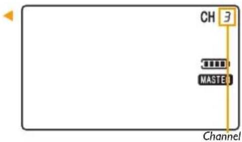
text_image
CH MASTER ChannelNote: all devices must be set to the same channel for the system to function properly.
ADJUSTING MASTER/SLAVE MODE ON THE TRANSCEIVER
Using the FreeWave Aviator System requires at least two units: one Transceiver set to Master mode and either a Receiver or a second Transceiver set to Slave mode. The Transceiver you are using to control your lighting must be set to Master mode.
To set a Transceiver to either Master or Slave mode, do the following:
- From the TTL Screen, press Menu twice. The device's current mode will start blinking.
- Toggle between Master and Slave mode using the + and - buttons.
- Press Select when the desired mode is displayed to apply the setting.
Note: when using a flash in the hot shoe atop a Transceiver set to Master mode, the flash will operate as a 4th TTL Group in "fully" automatic mode. Adjustments are limited to "fully" TTL (i.e. TTL EV Adjustments are not available) or Manual power settings.
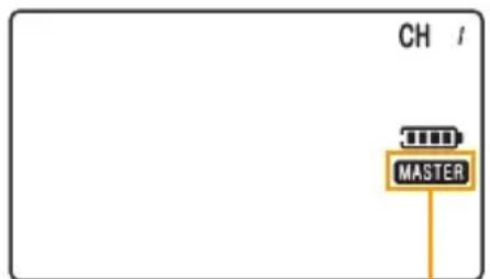
text_image
CH MASTERMaster Mode
Note: when a Transceiver is set to Slave mode, the Flash/Test button will not function.
SETTING FLASH GROUPS
Setting Flash Groups on the
Aviator Transceiver in Master Mode
The Aviator Transceiver allows individual control of flash settings for groups A, B and C. It can also fire all groups simultaneously.
To set the mode of a particular flash group, do the following:
- Press the desired group to toggle through the modes, (between TTL, Manual and OFF)
text_image
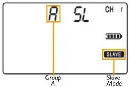
R SL CH / Group A Slave ModeSetting Flash Groups on the
Aviator Transceiver in Slave Mode
When the Transceiver is in Slave mode, set the desired group by pressing A, B, or C.
text_image
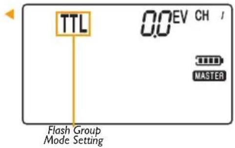
TTL 0.0 EV CH / MASTER Flash Group Mode SettingSetting the Group on the Aviator Receiver
Slide the Group switch on the Aviator Receiver to the desired Group (either A, B, or C).
To assign multiple Receivers to the same flash group, simply select the same group letter for each Receiver in the flash group.
Note: you can combine studio lights and speedlights within the same flash group. (Be aware of the independent recycling time of each flash to ensure all flash units are ready to fire).
Note: the Group D setting is reserved for factory calibration and is not available for use.

natural_image
Close-up of a hand holding a black DSLR camera module, no visible text or symbolsADJUSTING A FLASH GROUP'S TTL POWER (EV)
Using a Transceiver in Master mode:
- From the TTL Screen, press Select. The screen will start flashing.
- Press A, B, or C to select the desired flash group. The selected group will start flashing.
- Use the + and - buttons to set the EV (exposure) in TTL mode.
- Press Select twice when done to apply the settings.
- Press 4Test to confirm settings.
Note: 12 /Test fires a test flash on all connected hot-shoe lights and studio lights. It is advisable to always test fire your flashes after making changes to confirm your settings.
text_image
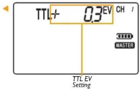
TTL+ 0.3EV CH / MASTER TTL EV SettingThe FreeWave Aviator has the ability to refine your flash output by adjusting a flash group's zoom. This function controls the concentration and diffusion of light emitted by your flash.
Using a Transceiver in Master mode:
- From the TTL Screen, press Select twice to enter Zoom Select.
- Press A, B, or C to select the desired Group.
-
Use + and - buttons to set the zoom level (Auto, 24, 28, 35, 50, 70, 80, or 105 mm) for the selected group (Auto is one level below 24 mm and appears as "Au").
-
Press Select when done to apply the setting.
- Press 4Test to confirm settings.
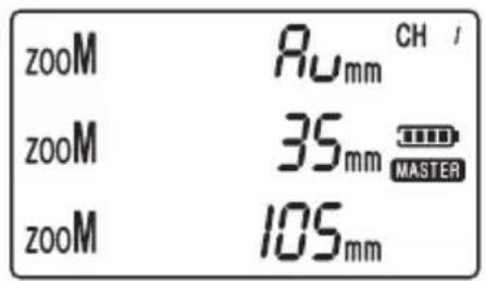
text_image
zooM Ruxmm CH / zooM 35mm MASTER zooM 105mmUSING TTL RATIO ADJUSTMENT MODES
Ratio Adjustment Mode gives you the convenience of not having to make individual adjustments to each flash group. You can make simple adjustments to the relationship between Group A and B, or Groups A, B and C (with Group C adjusting itself in relation to Group B), using a FreeWave Aviator Transceiver.
A standard portrait lighting setup uses a main (or key) light set at 100% power, a fill light at 50%, and a background light set as needed. In the device's Ratio Mode, you only need to adjust your ratio settings. The others will self-adjust and maintain their relative settings automatically.
For example, in Ratio A:B Mode, when setting the ratio as 2/1 (or 2:1), Group A will be twice as powerful as Group B.
In Ratio A:BC Mode, the device allows adjustments to the power of Group C in relation to Group B. Adjustments to Group C are set in EV. Each EV stop higher or lower will be either twice or half the power of the previous stop respectively (setting the EV to -1 would mean that Group C is 1 stop less powerful – or half the power of Group B). The EV can be adjusted in increments of 1/3 of a stop.
For example, in Ratio A:BC mode, if B is set to be half (-1 stop) of A, and C is set to an EV of -1 (1 stop less than B), C would actually be 1/4 (-2 stops) the power of A.

flowchart
graph TD
    A["Camera"] --> B["Group A (Key Light)"]
    B --> C["Group B (Fill Light)"]
    C --> D["Subject"]
    D --> E["Group C (Background Light)"]
Typical portrait lighting arrangement
Ratio A:B Mode
Using a Transceiver in Master mode:
- Set your TTL-compatible hot-shoe flash to TTL mode.
- From the TTL Screen, press Option to enter Ratio A:B Mode.
- Press Select to access the ratio adjustment.
- Use + and - buttons to adjust the ratio (up to 7 stops plus or minus).
- Press Select when done to apply the setting.
- Press 4Test to confirm settings.
Ratio A:BC Mode
Using a Transceiver in Master mode:
- From the TTL Screen, press Option twice to enter Ratio A:BC Mode.
- Press Select to access the ratio adjustment.
- Use + and - buttons to adjust the ratio (up to 7 stops plus or minus).
- Press Select to access an EV (exposure adjustment) to Group C, which will adjust its power in relation to group B.
-
Use the + and - buttons to adjust the EV ratio.
-
Press Select when done.
- Press 4Test to confirm settings.
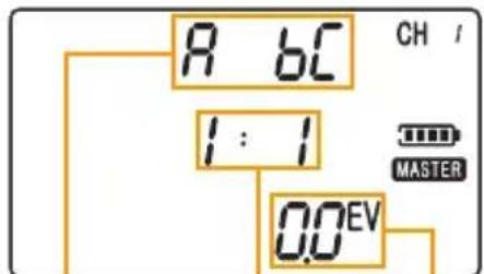
text_image
R 6C 1:1 0.0EV CH / MASTERRatio Mode Indicator
Group A:B Ratio Setting
Group C
EV Setting
CHANGING A FLASH GROUP'S POWER MODE
Set a Flash Group to Manual mode
Using a Transceiver in Master mode:
- Set your compatible TTL hot-shoe flash to TTL mode.
- From the Transceiver's TTL Screen, press the Select button, and the screen will begin to blink.
- Press the desired group button (A, B, or C) twice to set that group to manual mode.
-
Use the + and - buttons to adjust the manual power setting.
-
Press Select twice when done to apply the settings.
- Press 4Test to confirm settings.

text_image
M 1/1 CH / MASTERManual Flash Mode Power Setting
Turn a Flash Group Off
Using a Transceiver in Master mode:
- Press the desired group button (A, B, or C) to toggle through the power modes until you reach Off.
- Press 4Test to confirm settings.
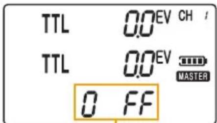
text_image
TTL 0.0 EV CH / TTL 0.0 EV MASTER 0 FFFlash Group set to Off
USING HIGH SPEED SYNC/SECOND CURTAIN SYNC MODES
For Nikon
The Vello FreeWave Aviator supports Hi-Speed Sync (HSS) up to 1/8000 of a second on compatible cameras and TTL flashes. This means that the entire duration of the shot, including the flash, can be as short as 1/8000 of a second.
The FreeWave Aviator also supports second-curtain sync mode on compatible cameras and TTL flashes.
Consult your camera's user manual to find out how to activate these modes.
Using a Transceiver in Master mode:
- From the TTL Screen choose a flash sync mode by pressing the Flash Sync Mode [×] button.
• Second Curtain Sync ( )
Note: High Speed Sync is controlled directly by the camera on Nikon systems – no settings are needed on the FreeWave Aviator.

text_image
TTL 0.0EV CH / TTL 0.0EV MASTER TTL 0.0EVSecond Curtain Sync Mode
Note: these functions work only with compatible cameras and TTL flashes.
For Canon
Using a Transceiver in Master mode:
- From the TTL Screen choose a flash sync mode by pressing the Flash Sync Mode [4] button to cycle through and choose an option.
• Second Curtain Sync ( )
- High-Speed Sync ( ?)
Note: Canon systems requires setting High Speed or Second Curtain Sync on the Transceiver.
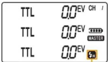
text_image
TTL 0.0EV CH / TTL 0.0EV MASTER TTL 0.0EVHigh Speed Sync Mode
SETTING AUTO-FOCUS ASSIST (NIKON ONLY)
To configure your Nikon flash's Auto-Focus Assist (AF Assist) from the Transceiver:
- Make sure your flash's AF Assist is turned on (see your flash's manual)
-
From the TTL Screen, press the Menu button three times
-
Press + or - to turn AF Assist On or Off
-
Press Select to apply the setting.
Note: for turning off a Nikon Camera's AF light, see your cameras manual.
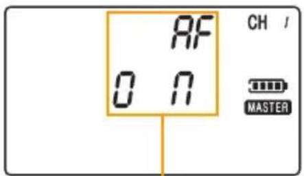
text_image
RF ON CH / MASTERAF Assist Setting
Note: for Canon systems, AF illumination is controlled directly by the flash (see your flash's manual)
ADDITIONAL FEATURES
TTL Pass-through
When a Transceiver is set to Master mode and mounted on your camera, a hot-shoe flash attached to its hot shoe receives TTL exposure data from the Master Transceiver unit to ensure that your photos will be properly exposed. It functions as a separate unit, independent of Groups A, B, and C. Adjustments to that flash are limited to Auto TTL (meaning that TTL EV adjustments are not available) or Manual power settings.

natural_image
Close-up of a hand adjusting a DSLR camera with a digital display and control panel (no visible text or symbols)Flash Wake-Up
If your flash has a wake-up function press the 4Test button on the Transceiver to wake your flash.
If your flash does not have a wake-up function, you may be able to turn off sleep mode: Refer to your flash's manual to find out if you can turn off sleep mode.
RESETTING THE TRANSCEIVER TO FACTORY DEFAULT SETTINGS
The FreeWave Aviator Transceiver remembers the last Group Mode, Channel, Zoom and Master/Slave settings when powered off. To reset your Transceiver to factory default settings, press and hold the Menu and Option buttons together for 3 seconds. The LCD display should show "All Settings Cleared."
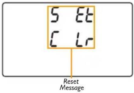
text_image
5 Et C Lr Reset Message| Channel | |
| Master/Slave Mode | |
| Flash Group Power Mode | |
| TTL Mode Power (EV) | s A,B, and C |
| Manual Mode Power | and C |
| Flash Zoom | |
| Ratio A:B Mode | |
| Ratio A:BC Mode | |
| Flash Sync Mode | |
| AF Assist (Nikon Only) |
SPECIFICATIONS
| Transceiver | Receiver | |
| Dimensions (W × H × D) | .25" (70 × 67 × 32 mm) | 1.75" × 1.25" × 3.19" (45 × 32 × 81 mm) |
| Weight (without battery) | 2.4 oz. (68 g) | |
| Power | 2 AA batteries (400 hrs. on standby) | |
| Output | Shoe | TTL hot shoe, PC sync port,3.5 mm sync port |
| Channels | 4 channels | |
| Groups | ||
| Range | ||
| Sync Speed | ||
| Flash Sync Modes | cond Curtain Sync | |
| EV Compensation | ||
TROUBLESHOOTING
- Check the contact between the light's hot shoe foot and the Receiver's hot shoe, and between the camera's hot shoe and the Transceiver's hot-shoe foot.
- Make sure the hot-shoe light's locking switch is set to the lock position.
- Make sure that the Receiver is powered on and at the correct setting.
-
Remove the batteries from the Transceiver and Receiver, wait a moment and then replace.
-
Change the channel by adjusting the switch on the Receiver and the setting on the Transceiver to a different combination, taking care to ensure that both the Transceiver and Receiver are set identically.
- Ensure that your TTL compatible flash is set to TTL mode, even when using the Transceiver to trigger in manual mode.
- After changing settings on the Aviator Transceiver, push the 5/Test button to confirm new settings.
FCC COMPLIANCE
This device complies with Part 15 of the FCC Rules. Operation is subject to the following two conditions:
- This device may not cause harmful interference.
- This device must accept any interference received, including interference that may cause undesired operation.
ONE-YEAR LIMITED WARRANTY
This VELLO product is warranted to the original purchaser to be free from defects in materials and workmanship under normal consumer use for a period of one (1) year from the original purchase date or thirty (30) days after replacement, whichever occurs later. The warranty provider's responsibility with respect to this limited warranty shall be limited solely to repair or replacement, at the provider's discretion, of any product that fails during normal use of this product in its intended manner and in its intended environment. Inoperability of the product or part(s) shall be determined by the warranty provider. If the product has been discontinued, the warranty provider reserves the right to replace it with a model of equivalent quality and function.
This warranty does not cover damage or defect caused by misuse, neglect, accident, alteration, abuse, improper installation or maintenance. EXCEPT AS PROVIDED HEREIN, THE WARRANTY PROVIDER MAKES NEITHER ANY EXPRESS WARRANTIES NOR ANY IMPLIED WARRANTIES, INCLUDING BUT NOT LIMITED TO ANY IMPLIED WARRANTY OF MERCHANTABILITY OR FITNESS FOR A PARTICULAR PURPOSE. This warranty provides you with specific legal rights, and you may also have additional rights that vary from state to state.
To obtain warranty coverage, contact the Vello Customer Service Department to obtain a return merchandise authorization (“RMA”) number, and return the defective product to Vello along with the RMA number and proof of purchase. Shipment of the defective product is at the purchaser’s own risk and expense.
For more information or to arrange service, visit www.vellogear.com or call Customer Service at 212-594-2353.
Product warranty provided by the Gradus Group.
www.gradusgroup.com
VELLO is a registered trademark of the Gradus Group.
© 2015 Gradus Group LLC. All Rights Reserved.

VELLO™
A Gradus Group Brand
www.vellogear.com
All other trademarks are the property of their respective owners.