EKI-1526T-VDC-BE - Server B&B Electronics - Free user manual and instructions
Find the device manual for free EKI-1526T-VDC-BE B&B Electronics in PDF.

User questions about EKI-1526T-VDC-BE B&B Electronics
0 question about this device. Answer the ones you know or ask your own.
Ask a new question about this device
Download the instructions for your Server in PDF format for free! Find your manual EKI-1526T-VDC-BE - B&B Electronics and take your electronic device back in hand. On this page are published all the documents necessary for the use of your device. EKI-1526T-VDC-BE by B&B Electronics.
USER MANUAL EKI-1526T-VDC-BE B&B Electronics
natural_image
Illustration of three server racks with network ports and connectors, no text or symbols presentEKI-1528/1526
8/16-port RS-232/422/485 Serial Device Server
Copyright
The documentation and the software included with this product are copyrighted 2008 by Advantech Co., Ltd. All rights are reserved. Advantech Co., Ltd. reserves the right to make improvements in the products described in this manual at any time without notice. No part of this manual may be reproduced, copied, translated or transmitted in any form or by any means without the prior written permission of Advantech Co., Ltd. Information provided in this manual is intended to be accurate and reliable. However, Advantech Co., Ltd. assumes no responsibility for its use, nor for any infringements of the rights of third parties, which may result from its use.
Acknowledgements
Intel and Pentium are trademarks of Intel Corporation.
Microsoft Windows and MS-DOS are registered trademarks of Microsoft Corp.
All other product names or trademarks are properties of their respective owners.
Product Warranty (2 years)
Advantech warrants to you, the original purchaser, that each of its products will be free from defects in materials and workmanship for two years from the date of purchase.
This warranty does not apply to any products which have been repaired or altered by persons other than repair personnel authorized by Advantech, or which have been subject to misuse, abuse, accident or improper installation. Advantech assumes no liability under the terms of this warranty as a consequence of such events.
Because of Advantech's high quality-control standards and rigorous testing, most of our customers never need to use our repair service. If an Advantech product is defective, it will be repaired or replaced at no charge during the warranty period. For out-of-warranty repairs, you will be billed according to the cost of replacement materials, service time and freight. Please consult your dealer for more details.
If you think you have a defective product, follow these steps:
-
Collect all the information about the problem encountered. (For example, CPU speed, Advantech products used, other hardware and software used, etc.) Note anything abnormal and list any onscreen messages you get when the problem occurs.
-
Call your dealer and describe the problem. Please have your manual, product, and any helpful information readily available.
-
If your product is diagnosed as defective, obtain an RMA (return merchandise authorization) number from your dealer. This allows us to process your return more quickly.
-
Carefully pack the defective product, a fully-completed Repair and Replacement Order Card and a photocopy proof of purchase date (such as your sales receipt) in a shippable container. A product returned without proof of the purchase date is not eligible for warranty service.
-
Write the RMA number visibly on the outside of the package and ship it prepaid to your dealer.
Part No. 2003152600 Edition 1
Printed in Taiwan October 2008
Declaration of Conformity
CE
This product has passed the CE test for environmental specifications when shielded cables are used for external wiring. We recommend the use of shielded cables. This kind of cable is available from Advantech. Please contact your local supplier for ordering information.
CE
This product has passed the CE test for environmental specifications. Test conditions for passing included the equipment being operated within an industrial enclosure. In order to protect the product from being damaged by ESD (Electrostatic Discharge) and EMI leakage, we strongly recommend the use of CE-compliant industrial enclosure products.
FCC Class A
Note: This equipment has been tested and found to comply with the limits for a Class A digital device, pursuant to part 15 of the FCC Rules. These limits are designed to provide reasonable protection against harmful interference when the equipment is operated in a commercial environment. This equipment generates, uses, and can radiate radio frequency energy and, if not installed and used in accordance with the instruction manual, may cause harmful interference to radio communications. Operation of this equipment in a residential area is likely to cause harmful interference in which case the user will be required to correct the interference at his own expense.
Technical Support and Assistance
- Visit the Advantech web site at www.advantech.com/support where you can find the latest information about the product.
- Contact your distributor, sales representative, or Advantech's customer service center for technical support if you need additional assistance. Please have the following information ready before you call:
– Product name and serial number
– Description of your peripheral attachments
– Description of your software (operating system, version, application software, etc.)
– A complete description of the problem
– The exact wording of any error messages
Safety Instructions
- Read these safety instructions carefully.
- Keep this User Manual for later reference.
- Disconnect this equipment from any AC outlet before cleaning. Use a damp cloth. Do not use liquid or spray detergents for cleaning.
-
For plug-in equipment, the power outlet socket must be located near the equipment and must be easily accessible.
-
Keep this equipment away from humidity.
-
Put this equipment on a reliable surface during installation. Dropping it or letting it fall may cause damage.
-
The openings on the enclosure are for air convection. Protect the equipment from overheating. DO NOT COVER THE OPENINGS.
-
Make sure the voltage of the power source is correct before connecting the equipment to the power outlet.
-
Position the power cord so that people cannot step on it. Do not place anything over the power cord.
-
All cautions and warnings on the equipment should be noted.
-
If the equipment is not used for a long time, disconnect it from the power source to avoid damage by transient overvoltage.
-
Never pour any liquid into an opening. This may cause fire or electrical shock.
-
Never open the equipment. For safety reasons, the equipment should be opened only by qualified service personnel.
-
If one of the following situations arises, get the equipment checked by service personnel:
-
The power cord or plug is damaged.
– Liquid has penetrated into the equipment.
– The equipment has been exposed to moisture. -
The equipment does not work well, or you cannot get it to work according to the user's manual.
– The equipment has been dropped and damaged.
– The equipment has obvious signs of breakage. -
DO NOT LEAVE THIS EQUIPMENT IN AN ENVIRONMENT WHERE THE STORAGE TEMPERATURE MAY GO BELOW -20°C (-4°F) OR ABOVE 60°C (140°F). THIS COULD DAMAGE THE EQUIPMENT. THE EQUIPMENT SHOULD BE IN A CONTROLLED ENVIRONMENT.
-
CAUTION: DANGER OF EXPLOSION IF BATTERY IS INCORRECTLY REPLACED. REPLACE ONLY WITH THE SAME OR EQUIVALENT TYPE RECOMMENDED BY THE MANUFACTURER, DISCARD USED BATTERIES ACCORDING TO THE MANUFACTURER'S INSTRUCTIONS.
-
The sound pressure level at the operator's position according to IEC 704-1:1982 is no more than 70 dB (A).
DISCLAIMER: This set of instructions is given according to IEC 704-1. Advantech disclaims all responsibility for the accuracy of any statements contained herein.
Chapter 1 Introduction......1
1.1 Overview ...... 2
1.2 Features 2
1.3 Product Specifications.... 3
1.3.1 LAN 3
1.3.2 Serial Communications 3
1.3.3 Software Features.... 3
1.3.4 Mechanical.... 3
1.3.5 General 4
1.3.6 Power Requirements .... 4
1.3.7 Environment....4
1.3.8 Regulatory Approvals.... 4
1.4 Package Checklist.... 4
Chapter 2 Getting Started......5
2.1 Understanding the EKI-1528/1526.... 6
2.1.1 COM Port Redirector (Virtual COM) 7
2.1.2 TCP Server (Data Mode) 8
2.1.3 TCP Client (Data Mode)....9
2.1.4 Serial Tunneling Mode 9
2.1.5 UDP Mode (Data Mode) 10
2.1.6 Control Mode 10
2.2 Hardware.... 11
2.2.1 Panel Layout 11
2.2.2 LED Indicators 12
Table 2.1: EKI-1528/1526 LED Indicators 12
2.2.3 Dimensions (Unit: mm) 12
2.3 Connecting Hardware 13
2.3.1 Rack Mount.... 13
2.3.2 Connecting EKI-1528/1526's Power 14
2.3.3 Connecting to the Serial Devices.... 14
Table 2.2: EKI-1528/1526 Serial Port Pin Assignments ..... 14
2.3.4 Connecting to a Host or the Network 14
2.3.5 Connecting to the Serial Console Port.... 14
2.4 Installing the Configuration Utility.... 15
Chapter 3 Configuration....17
3.1 Configuration Utility Overview 18
3.2 Discovering Serial Device Servers....19
3.2.1 Auto Searching 19
3.2.2 Clear Device List and Search Again 21
3.2.3 Manual Appending 22
ork Settings 23
Settings 24
Operation Mode Settings 28
3.5.1 Virtual COM Mode 28
3.5.2 Data Mode (USDG Mode) 29
3.5.3 Control Mode (USDG Mode).... 32
Table 3.1: AT Command List.... 33
ssible IP Settings.... 34
Auto Warning Settings 34
3.7.1 Email Alert.... 34
3.7.2 SNMP Trap 35
3.7.3 System Event.... 35
3.7.4 Serial Port Event 36
3.8 Port Monitor 37
3.9 Administrator Settings.... 38
3.9.1 Import/Export Device Setting 38
3.9.2 Import/Export Serial Port Setting 39
3.9.3 Locate the Serial Device Server 39
3.9.4 Lock the Serial Device Server (Password Protection) 39
3.9.5 Restore to Factory Default Settings.... 41
3.9.6 Update Firmware 42
Chapter 4 Setting COM Redirector .... 45
4.1 Setting COM Redirector(Virtual COM port)...... 46
Chapter 5 Web-Based Configuration.... 55
5.1 Overview 56
5.2 Accessing the Web Page.... 56
5.3 System 58
5.4 Network Configuration 58
5.5 Port Configuration 59
5.6 Monitor 60
5.7 Auto Warning (Alarm) 61
5.8 Change Password....62
5.9 Import/Export Device Settings 64
5.10 Reboot 65
Chapter 6 Telnet/Serial Console Configuration67
6.1 Overview 68
6.2 Telnet Console.... 68
6.3 Serial Console.... 69
6.4 Command List....71
Table 6.1: Console Command List .... 71
Appendix A Pin Assignments....83
A.1 Pin Assignments 84
A.1.1 RS-232 Pin Assignments.... 84
A.1.2 RJ-45 Cable PIN Assignments 84
Chapter 1
Introduction
1.1 Overview
This manual provides the necessary information to use the EKI-1528 and EKI-1526. The Advantech EKI-1500 series of serial device servers consist of fast and cost-effective device servers between serial RS-232/422/485 and Ethernet interfaces.
The two Ethernet ports allow the EKI-1528/1526 to establish two separate Ethernet connections to two Ethernet domains or switches in the same domain. Through dual Ethernet connections, the EKI-1528/1526 greatly improves the device connectivity reliability, increases system stability, and simplifies redundant configuration.
By encapsulating serial data and transporting it over Ethernet, the EKI-1528/1526 allows virtual serial links over Ethernet and IP (TCP/IP, UDP/IP) networks. After Advantech Serial Device Server Configuration Utility (including COM port redirector driver) installation, standard serial operation calls are transparently redirected to the serial device servers, guaranteeing compatibility with legacy serial devices and enabling backward compatibility with existing software. The EKI-1528/1526 also supports serial tunneling, allowing two native serial devices to communicate over a network without any hosts and programming. As a result, you can extend limited distance, point-to-point, direct serial connections within the plant, throughout the factory, the facility, the office building, or across the global enterprise.
The EKI-1528/1526 provides various operation modes including COM port redirector (Virtual COM port), TCP server mode, TCP client mode, and UDP mode. These units upgrade your existing device for integrating into the Internet world, and make your serial devices behave just like the networking devices.
The EKI-1528/1526 provides rich configuration methods: web browser console, Telnet console, serial interface console, and Windows utility. Each method ensures quick and effective installation. The EKI-1528/1526 also supports automatic IP configuration protocol including DHCP and BOOTP.
1.2 Features
■ Supports 8 or 16-ports RS-232/422/485 serial communication
■ Supports dual 10/100 Mbps auto-sensing Ethernet ports
■ Supports high baud rate from 50 bps to 921.6 Kbps
■ Provides COM port redirection mode, TCP server mode, TCP client mode, and UDP mode
■ Provides rich configuration methods: web browser console, Telnet console, serial console, and Windows utility
■ Easy-managing Advantech Serial Device Server Configuration Utility for Windows 2000/XP/Vista(x86)
■ Built-in buzzer for easy location
Built-in 15 KV ESD protection for all signals and enhancement protection for RS-422/485 lines
■ Standard 1U rackmount size
■ Automatic RS-485 data flow control
1.3 Product Specifications
1.3.1 LAN
■ Compatibility: IEEE802.3, IEEE802.3u
■ Speed: 10/100 Mbps, auto MDI/MDIX
No. of Ports: 2
■ Port Connector: 8-pin RJ45 (with LED)
■ Protection: Built-in 1.5 KV magnetic isolation
1.3.2 Serial Communications
■ Port Type: RS-232/422/485, software selectable
No. of Ports: 8/16
■ Port Connector: 8-pin RJ45
Data Bits: 5,6,7,8
■ Stop Bits: 1,1.5,2
■ Parity Bits: None, Odd, Even, Space, Mark
■ Flow Control: XON/XOFF, RTS/CTS, DTR/DSR
■ Baud Rate: 50 bps to 921.6 Kbps
Serial Signals:
- RS-232: TxD, RxD, CTS, RTS, DTR, DSR, DCD, GND
- RS-422: TxD+, TxD-, RxD+, RxD-, GND
- RS-485: Data+, Data-, GND
■ Protection: 15 KV ESD protection for all signals
1.3.3 Software Features
■ Driver Support: Windows 2000/XP/Vista(x86)
■ Utility Software: Advantech Serial Device Server Configuration Utility
Operation Modes:
- COM port redirection mode (Virtual COM)
- TCP/UDP server (polling) mode
- TCP/UDP client (event handling) mode
– Pair connection (peer to peer) mode
Configuration: Web Browser, Telnet Console, Windows Utility, or Serial Console
Protocols: ICMP, IP, TCP, UDP, BOOTP, DHCP, Auto IP, Telnet, SNMP, HTTP, DNS, SMTP, ARP
■ Management: SNMP MIB-II
1.3.4 Mechanical
■ Material: SECC sheet metal chassis
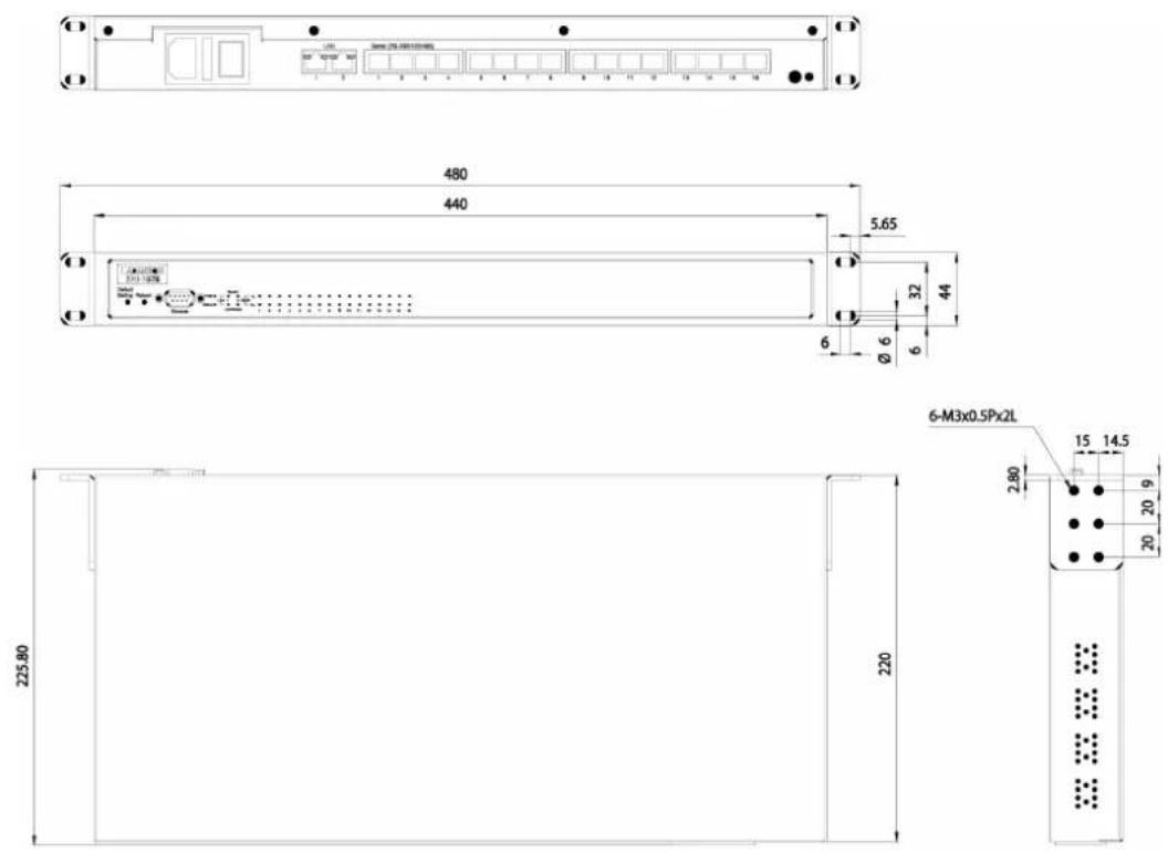
■ Dimensions (H x W x D): 44 x 440 x 220 mm
Weight:
- EKI-1528: 2.53 Kg
- EKI-1526: 2.58 Kg
1.3.5 General
LED Indicators:
– System: Power, System Status
– LAN: Speed, Link/Active
- Serial: Tx, Rx
■ Alert Tool: Built-in buzzer and RTC (real time clock)
■ Reboot Trigger: Built-in WDT (watchdog timer)
1.3.6 Power Requirements
■ Power Input: 100 to 240 VAC, 47 to 63 Hz
■ Power Consumption:
- EKI-1528: 8W
- EKI-1526: 10W
1.3.7 Environment
■ Operating Temperature: 0 to 60 °C (32 to 140°F)
■ Storage Temperature: -20 to 85 °C (-4 to 185 °F)
■ Operating Humidity: 5 to 95% RH
1.3.8 Regulatory Approvals
■ EMC: CE Class A, FCC Part 15 Subpart B Class A
■ One 8 or 16-port serial device server
■ EKI-1500 IEDG driver utility and documentation CD
■ One 30cm RJ45 to DB9 cable for serial connection
- Rack mount kits, including 2 L-shape metal plates and 12 screws
■ One RS-232 loopback DB9 tester
Optional Accessories
■ OPT1I: 1m RJ45 to DB9 (male) cable
■ OPT1J: 30cm RJ45 to DB9 (male) cable
■ 1702002600: Power Cable US Plug 1.8m
■ 1702002605: Power Cable EU Plug 1.8m
■ 1702031801: Power Cable UK Plug 1.8m
■ 1702031836: Power Cable China/Australia Plug 1.8m
Note! If anything is missing or damaged, contact your distributor or sales representative immediately.

Chapter 2
Getting Started
2.1 Understanding the EKI-1528/1526
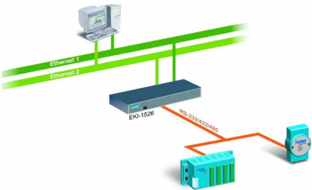
The EKI-1528/1526 is network-based, serial device server for connecting RS-232/422/485 serial devices, such as PLCs, CNCs, scales, and scanners, directly to a TCP/IP network. Once connected through the EKI-1528/1526, the serial devices will be able to send and receive data on a network like any other network devices. It extends traditional COM ports of a PC with access over a TCP/IP network. Through networking, you can control and monitor remote serial devices either over a LAN or over the WAN. Since the EKI-1528/1526 is connected through a TCP/IP network, you might need to know some basic facts about networking in order to get the server hooked up correctly.
After the simple installation steps to attach your network and serial device to the appropriate connectors on the serial device servers and driver installation, you will then be able to communicate with the serial devices via its own application software and with the EKI-1500 serial device servers. COM port redirector, TCP server mode, TCP client mode, UDP server mode, UDP client mode and Control mode are all different schemes to make a serial connection across using one or more Serial device server.
The EKI-1528/1526 provides dual Ethernet ports that can establish two physical Ethernet connections. Dual connections enable an alternative backup session that host can connect to device server by the way of second connection while the primary connection should be lost or dropped.
flowchart
graph TD
    A["Ethernet 1"] --> B["Router"]
    C["Ethernet 2"] --> B
    B --> D["RS-232/422/485"]
    D --> E["ADAM Device"]
    F["EKI-1526"] --> D
    style A fill:#f9f,stroke:#333
    style C fill:#f9f,stroke:#333
    style F fill:#ccf,stroke:#333
    style D fill:#cff,stroke:#333
    style E fill:#ffc,stroke:#333
2.1.1 COM Port Redirector (Virtual COM)
Advantech serial device server configuration utility is a serial COM port redirector that creates virtual COM ports and provides access to the serial devices connected to Advantech serial device servers. You can configure the serial device server and enable the virtual COM port using one integrated utility. Advantech serial device server configuration utility allows you to configure Microsoft applications to communicate with network enabled serial device servers as easily as if they were physically installed in or directly connected to the PC.
The Advantech redirector can create up to 255 virtual COM ports. Application on the host can open virtual COM port to access the serial device servers at the same time. The redirector will handle each active virtual COM port as a separate TCP connection to Advantech serial device servers.
Normal Mode
The Advantech redirector connects the Advantech serial device servers while an application open the COM port and disconnects from the Advantech serial device servers when the application closes the COM port. The redirector uses TCP network connections to the Advantech serial device server to gain the access to the connected serial devices.
Multi-Access Mode (Shared COM Port Mode)
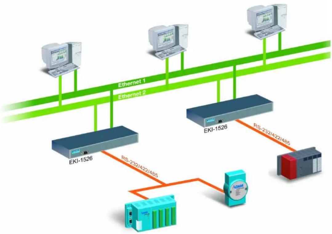
Most of serial devices are connected directly and physically to the PC serial ports via a cable. The operation system, ex. Windows XP, provides the COM ports that user's application can access, and control the serial device through the serial cable. This means that the serial device can be connected to one host and only one application on this host can handle input, output and control operation on this device.
If you want to run more than one applications to use same serial device, you can employ EKI-1500 serial device servers that provide a virtual COM port for a host or multi-hosts on an Ethernet network. EKI-1500 serial device server is located between hosts and serial devices. Each serial port on the EKI-1500 serial device server can allow the maximum of 5 host connections through one Ethernet port or two Ethernet ports. There are two major operation modes for Multi-Access Mode. First one is broadcast mode; the EKI-1500 serial device server handles a command from one application and replies the data from the serial port to all applications that are connecting this serial port. Another one is polling mode; the EKI-1500 serial device server handles the command from one application and reply to this application only. Query from other applications must be queued and wait for current process completing.
By using a serial derive server to share serial device, you eliminate the separate serial lines and serial devices that can be attached to individual hosts. Collecting the data from these serial devices become more easily and more effectively.
flowchart
graph TD
    A["EKI-1526"] -->|RS-232/422/485| B["ADAM"]
    C["EKI-1526"] -->|RS-232/422/485| D["ADAM"]
    E["EKI-1526"] -->|RS-232/422/485| F["ADAM"]
    G["EKI-1526"] -->|RS-232/422/485| H["ADAM"]
    I["EKI-1526"] -->|RS-232/422/485| J["ADAM"]
    K["EKI-1526"] -->|RS-232/422/485| L["ADAM"]
    M["EKI-1526"] -->|RS-232/422/485| N["ADAM"]
    O["EKI-1526"] -->|RS-232/422/485| P["ADAM"]
    Q["EKI-1526"] -->|RS-232/422/485| R["ADAM"]
    S["EKI-1526"] -->|RS-232/422/485| T["ADAM"]
    U["EKI-1526"] -->|RS-232/422/485| V["ADAM"]
    W["EKI-1526"] -->|RS-232/422/485| X["ADAM"]
    Y["EKI-1526"] -->|RS-232/422/485| Z["ADAM"]
    AA["EKI-1526"] -->|RS-232/422/485| AB["ADAM"]
    AC["EKI-1526"] -->|RS-232/422/485| AC
    AD["EKI-1526"] -->|RS-232/422/485| AE["ADAM"]
    AF["EKI-1526"] -->|RS-232/422/485| AG["ADAM"]
    AH["EKI-1526"] -->|RS-232/422/485| AI["ADAM"]
    AJ["EKI-1526"] -->|RS-232/422/485| AK["ADAM"]
    AL["EKI-1526"] -->|RS-232/422/485| AM["ADAM"]
    AN["EKI-1526"] -->|RS-232/422/485| AO["ADAM"]
    AP["EKI-1526"] -->|RS-232/422/485| AQ["ADAM"]
    AR["EKI-1526"] -->|RS-232/422/485| AS["ADAM"]
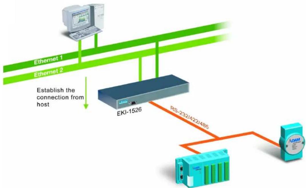
2.1.2 TCP Server (Data Mode)
In the TCP server mode, you might initiate the TCP connection from host to the EKI-1500 serial device server. This operation mode supports a max. of 5 simultaneous connections for each serial port on the EKI-1500 serial device server from one host or several hosts, however multi-hosts collect the data from one serial port at the same time.
flowchart
graph TD
    A["Ethernet 1"] --> B["EKI-1526"]
    C["Ethernet 2"] --> B
    B --> D["RS-232/422/485"]
    D --> E["ADAM"]
    style A fill:#f9f,stroke:#333
    style C fill:#f9f,stroke:#333
    style B fill:#ccf,stroke:#333
    style E fill:#cfc,stroke:#333
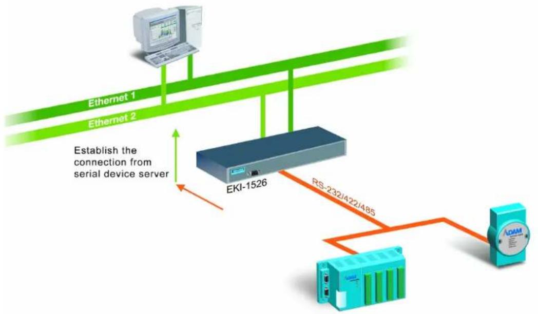
2.1.3 TCP Client (Data Mode)
In the TCP Client mode, the TCP connection will be established from the EKI-1500 serial device server. This operation mode supports a max. of 16 simultaneous connections for each serial port on the EKI-1500 serial device servers to one host or several hosts. You should configure the IP address and TCP port number of the network hosts which the EKI-1500 serial device server connect to using Advantech Serial Device Server Configuration Utility. After configuration, when EKI-1500 serial device server receives the data from serial port, the device server will employ the connection to hosts which are configured.
flowchart
graph TD
    A["Eki-1526"] -->|RS-232J422J48S| B["ADAM"]
    C["Ethernet 1"] --> D["Ethernet 2"]
    D -->|Establish the connection from serial device server| A
2.1.4 Serial Tunneling Mode
Two native serial devices can communicate over an Ethernet network without any intermediate host PC and software programming. Serial Tunneling is very simple to use. You can use Advantech Serial Device Server Configuration Utility to designate one serial port as the tunneling master and another serial device server port as the tunneling slave.
flowchart
graph TD
    A["EKI-1526"] -->|RS-232/422/485| B["AnM Device"]
    C["EKI-1526"] -->|RS-232/422/485| D["AnM Device"]
    B --> E["AnM Device"]
    D --> F["AnM Device"]
2.1.5 UDP Mode (Data Mode)
UDP is used primarily for broadcasting messages over a network. In the UDP server mode, the EKI-1500 serial device server accesses a max. of 8 hosts' UDP message. In the UDP client mode, the EKI-1500 serial device server transmits UDP message to a max. of 16 hosts simultaneously.
flowchart
graph TD
    A["TCP / IP Ethernet"] --> B["EKI-1526"]
    B --> C["RS-232/422/485"]
    C --> D["Temperature/Humidity"]
    C --> E["Lighting"]
    C --> F["Fire Alarm"]
    C --> G["Power Meter"]
    B --> H["No connection required"]
2.1.6 Control Mode
In the control mode, the EKI-1500 serial device server presents a modem interface to the attached serial device: it accepts AT-style modem commands to connect / disconnect to other networking device. If you want serial device running application program to connect/disconnect to different devices by request, you can use the control mode.
The control mode provides three kinds of modem AT-style commands. The serial devices can use these commands to control the EKI-1500 serial device server connecting or disconnecting to remote networking devices. Thus intelligent serial devices such as stand-alone PLC will send /receive data to/from devices one by one via Ethernet.
2.2 Hardware
In this section, it will give you an overview of the EKI-1528/1526 hardware and installation.
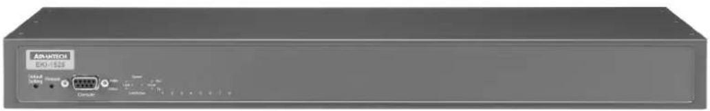
2.2.1 Panel Layout
EKI-1526: Front View
natural_image
Front view of an IEEE EKI-1326 network device (no visible text or symbols on the device body)EKI-1526: Rear View
natural_image
Front view of a network switch interface with I/O ports and serial port (no visible text or labels beyond port numbers)EKI-1528: Front View
natural_image
Front view of an Ethernet EC21589 device showing ports and indicator lights (no readable text beyond branding)EKI-1528: Rear View

natural_image
Front view of a network switch device showing LAN and Serial port ports (no readable text or symbols)Reboot Button
Press the reboot button to reboot the EKI-1528/1526.
Default Setting Button
The EKI-1528/1526 will be set back to the factory default settings after you keep pressing this button about 10 seconds. (The Status LED will be off and then start to blink again while the system rebooting success.)
2.2.2 LED Indicators
There are LEDs display the power status, system status, dual Ethernet networks status, and serial communication status on the front panel of the EKI-1528/1526. Each of them has its own specific meaning as below table.
| Table 2.1: EKI-1528/1526 LED Indicators | |
| LED Name LED Color LED Description | |
| PWR Green Power is on | |
| Off Power is off, or power error condition exists | |
| Status Orange Blinking: System is readySteady on: The device server has been located by utility's locating the device function | |
| Off System is not working | |
| Ethernet Orange Blinking: Ethernet port is transmitting or receiving dataSteady on: Ethernet has the good link for 10Mbps or 100Mbps operations | |
| Green On: 100Mbps Ethernet connectionOff: 10Mbps Ethernet connection | |
| Serial Orange Serial port is transmitting data | |
| Green Serial port is receiving data | |
| Off No data is transmitted or received through the serial port | |
2.2.3 Dimensions (Unit: mm)
2.3 Connecting Hardware
This section introduces how to connect the EKI-1528 or EKI-1526 to serial devices for first time.
2.3.1 Rack Mount
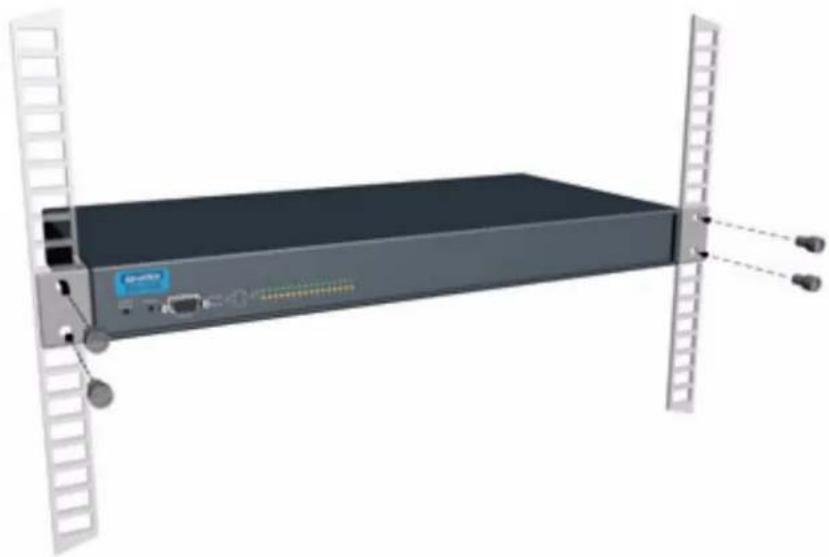
natural_image
3D rendering of a server rack with two vertical racks and a front panel, no visible text or symbols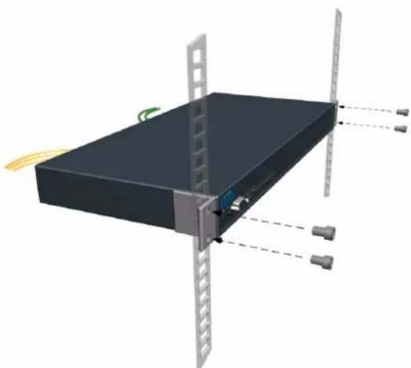
natural_image
3D diagram of a server rack with connected components and wiring, no visible text or symbols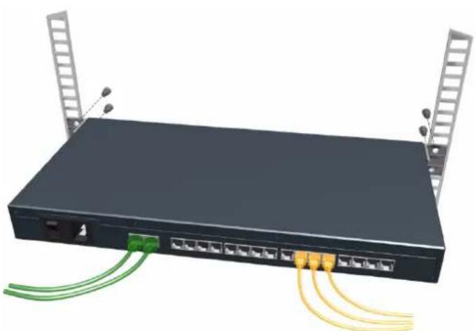
natural_image
Black network switch device with multiple Ethernet ports and two vertical ladders on top (no text or symbols visible)2.3.2 Connecting EKI-1528/1526's Power
Connect the EKI-1528 or EKI-1526 AC power line with its AC connector. If the power is properly supplied, you can turn on the power switch and the PWR LED will show a green color.

natural_image
Close-up of a black electrical switch panel with three ports and a fuse (no visible text or symbols)2.3.3 Connecting to the Serial Devices
The EKI-1528/1526 provides 8 or 16 RJ45 connectors. Connect the serial data cable between the EKI-1528/1526 and the serial devices. The RS-232/422/485 pin assignments are as below.
| Table 2.2: EKI-1528/1526 Serial Port Pin Assignments | |||||||||
| P | i | n | 1 | 2 | 3 | 4 | 5 | 6 | 7 |
| RS-232 | DCD | RX | TX DTR | GND DSR | RTS | CTS | |||
| RS-422 | TX- | TX+ | RX+ | RX- | GND | - | - | - | |
| RS-485 | Data- | Data+ | - | - | GND | - | - | - | |
8
2.3.4 Connecting to a Host or the Network
The EKI-1528/1526 provides two RJ45 connectors with dual independent Ethernet networks, and supports 10/100 Mbps transmission speed. The EKI-1528/1526 will auto detect current transmission speed on the network and configure itself accordingly. For normal operation, the EKI-1528/1526 can be connected to other hubs or switches through a twisted-pair straight through the Ethernet cable. For configuration or troubleshooting purposes, user may need to connect the EKI-1528/1526 directly to the host PC. In this operation mode, user can use an Ethernet cable to connect the EKI-1528/1526 to the host PC's Ethernet connector directly due to the EKI-1528/1526 supports auto MDI/MDIX functions.
2.3.5 Connecting to the Serial Console Port
Connect to the Serial Consol port using directly cable with DB9 male connector. Refer to Chapter 6 for details.
2.4 Installing the Configuration Utility
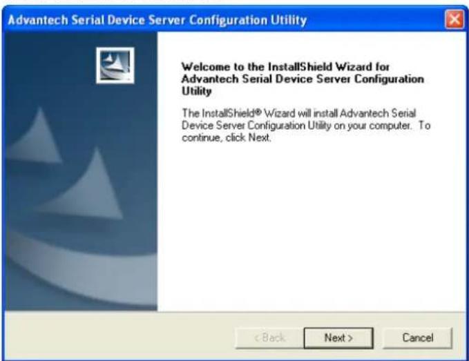
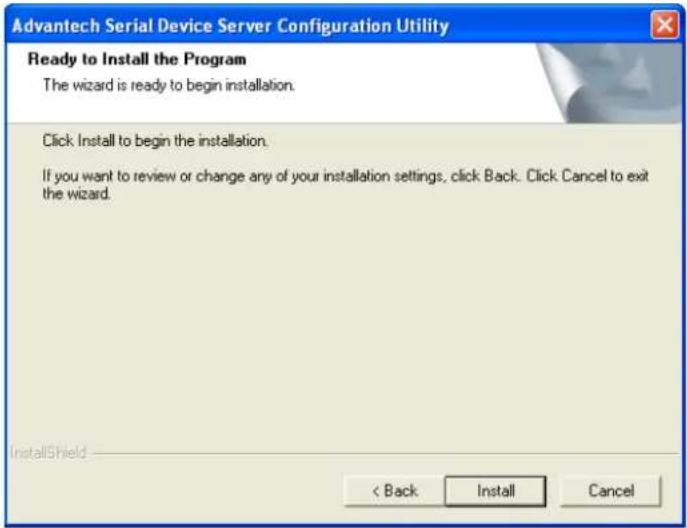
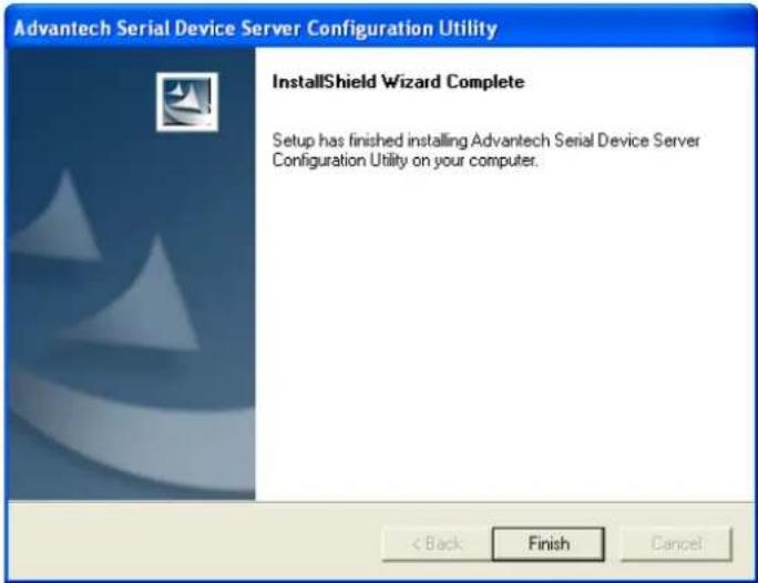
The following section will show you how to install the Advantech serial device server configuration utility, a tool to set up and monitor the EKI-1500 serial device servers.
Note! Be sure the Microsoft .NET Framework on your host PC is greater than version 2.0.

- Insert the Advantech industrial communication IEDG series driver utility CD into the CD-ROM drive (e.g. E:) on the host PC.
- Use Windows explorer or the Windows Run command to execute the setup program, the path for the setup program on the CD-ROM should be: E:\Utility&Driver\SerialDeviceServerConfigurationUtility\Serial_Device_Server_Configuration_Utility_[Version]_Release_[date].exe
- Upon executing the setup program, the Welcome Dialog Box will be pop-up. Press the "Next" button to continue.
- Carefully read the Software License Agreement, and press "Yes" to continue.

- The Setup program will specify a default installation path: C:\Program Files\Advantech eAutomation\Serial Device Server Configuration Utility\
- After setup has copied all program files to your computer, click the
button to finish the installation.
Chapter 3
Configuration
3.1 Configuration Utility Overview
EKI-1500 serial device servers provide an easy-to-use utility to configure your serial device server through an Ethernet connection. For secure administration, it can also restrict the access rights for configuration to only one host PC. With this secure function enabled, other PCs will not have permission for configuration. After the installation program on the Advantech IEDG Series Driver Utility CD-ROM is finished, the serial device servers will be ready for use and configure.
Advantech Serial Device Server Configuration Utility is an excellent device server management tool. You can connect and configure the local and remote Advantech serial device servers easily. Moreover, Virtual COM port will be enabled in the same utility. Using this utility, you can:
Configure the network settings (you can set the IP address, Gateway address, and Subnet mask)
■ View and set the serial port parameters (configure operating mode, baud rate, serial port settings and operating mode settings)
■ Perform diagnostic tests (virtual COM port testing, port status list)
■ Perform administrative functions (export and import the serial device server setting, manage access IP, a descriptive name, upgrade firmware)
■ Configure COM port redirector (virtual COM port)
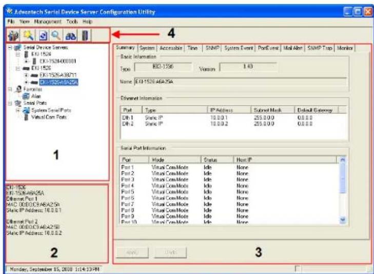
You may open the Serial Device Server Configuration Utility from the Windows Start Menu by clicking Start → All Programs → Advantech eAutomation → Serial Device Server Configuration Utility. The Serial Device Server Configuration Utility will appear as below.
There are four major areas in this new serial device server configuration utility.
- Serial Device Server List Area: All devices will be searched and listed in this area. You can arrange different favorite group and virtual COM ports.
- Serial Device Server Information Area: Click on the serial device server or move cursor to the serial device server, the related information will be shown on this area.
- Configuration Area: Click on the item on the Device Server List Area, the configuration page will display on the area.
- Quick Tool Bar: Useful management functions shortcut.
Note! Please reserve TCP/UDP port 5048 and 5058 in your Ethernet network, configuration utility will use these ports to communicate with Advantech EKI-1000, ADAM-4570, and EDG-4500 serial device servers.
3.2 Discovering Serial Device Servers
3.2.1 Auto Searching
Advantech Serial Device Server Configuration Utility will automatically search all the EKI-1000, ADAM-4570 and EDG-4500 series device servers on the network and show them on the Serial Device Server List Area of the utility. The utility provides an auto-search function to show your device(s) by simply executing the configuration utility program from the Start Menu.
From here all device on the same network domain will be searched and display on Device Server List Area. You can click on the device name to show the features of the specific device. Click on the "+" before the model name (e.g. EKI-1526), and the utility will expand the tree structure to show the individual device name. Click on the "-" before the model name (e.g. EKI-1526), and the utility will collapse the tree structure.
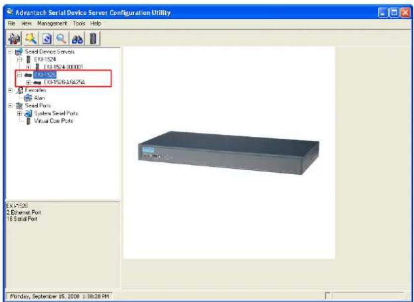
For example, the EKI-1526 in this figure is shown "EKI-1526-A6A25A" after expanding the tree structure.
Note!
When you run the Configuration Utility for the first time, the default device name is "MAC ID". In this case, the device name "EKI-1526-A6A25A" means the device "MAC ID" is "00 D0 C9 A6 A2 5A". You can change the default device name in the System Tab of Device Properties.

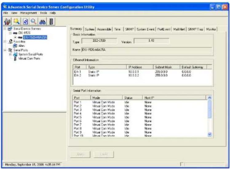
Select the device in this sub-tree. The first tab on the "Configuration Area" shows the summary of "Basic Information" included device type, version, and name, "Ethernet Information", and "Serial Port Information". In the serial port information frame, it displays the operation mode, status and connected host IP.
Click on the “+” before the device name, and the utility will expand the interfaces on this device server.
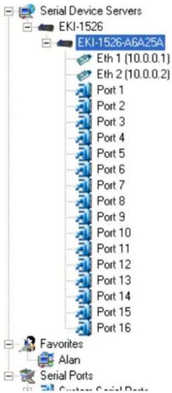
Click on each item, you will entry the configuration page to change the setting. The configuration will be introduced on following sections.
3.2.2 Clear Device List and Search Again
You can click the button on the Quick Tool Bar. The utility will clear all list device servers in the Serial Device Server List Area and re-search again. Don't use this function frequently. The warning message will be pop-up when you double click this button.

You can click the button on the "Quick Tool Bar". The utility will search serial device server on local LAN.
3.2.3 Manual Appending
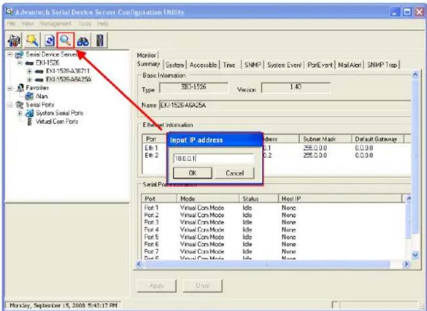
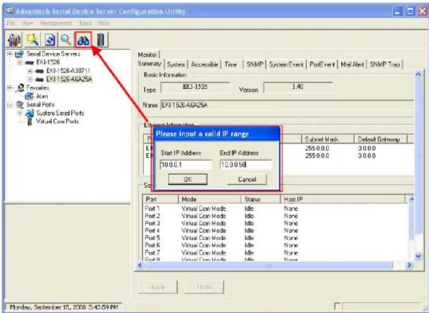
Using "Add IP address to Favorite" or "Search a Range of IP addresses" function, you are able to add one device or group of devices to "Favorites". These devices can locate on local network domain or other network domain.
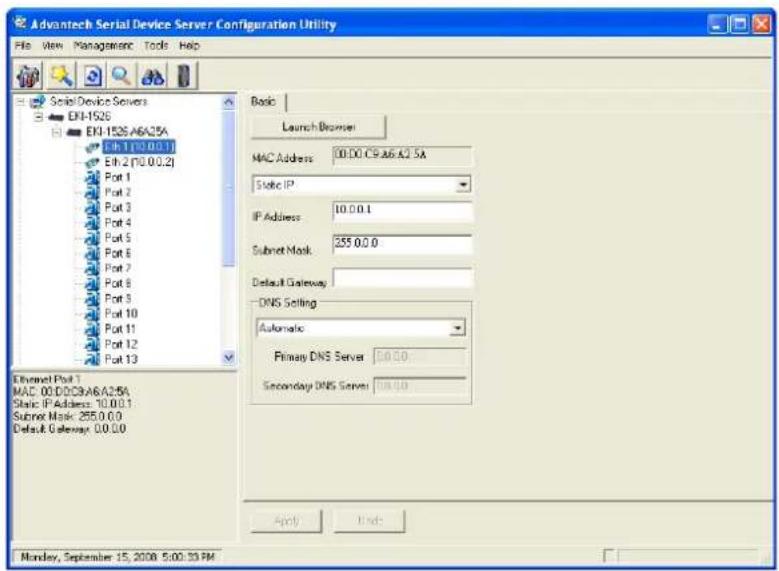
3.3 Network Settings
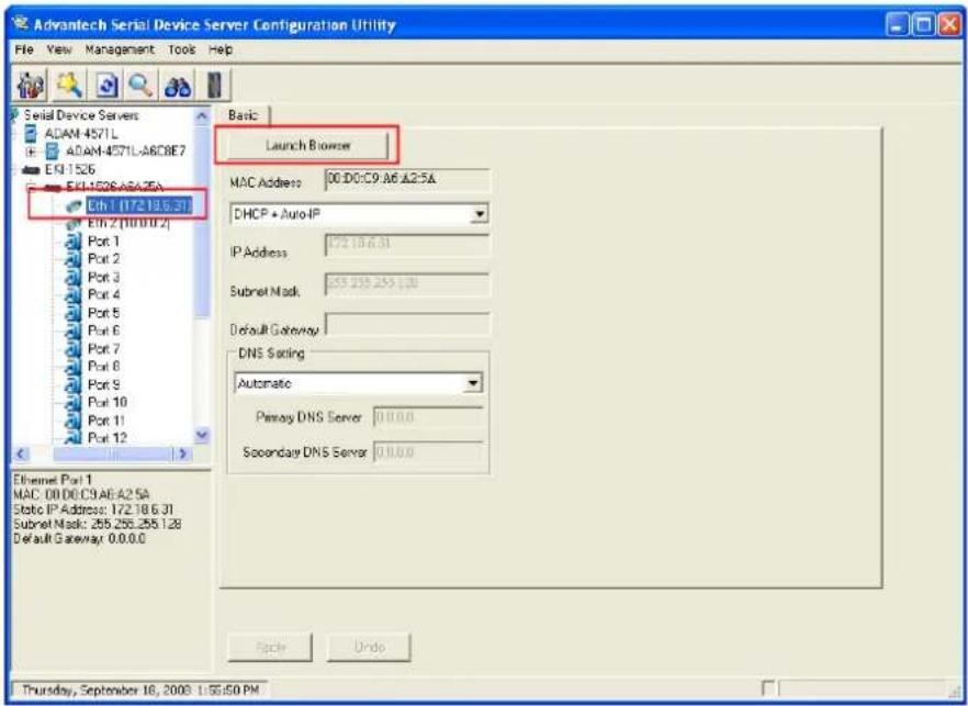
This section explains how to configure the EKI-1528/1526 network using this utility so that it can communicate over a network with serial devices.
Click on the “+” before the model name (e.g. EKI-1526), and the utility will expand the tree structure to show the individual device name. And click on the “+” before the device name, and the utility will expand the interfaces on this device server. Select the Ethernet interface. (Select Eth1 or Eth2, these are two individual Ethernet ports)
MAC address:
The MAC address is for the local system to identify and locate each serial device servers. This MAC address is already set before delivery from factory, hence no need for further configuration.
IP address, Subnet Mask, Default Gateway:
You can choose from four possible IP Configuration modes --- Static, DHCP, BOOTP, and DHCP/BOOTP.
Static IP
User defined IP address, Subnet Mask, and Default Gateway.
DHCP + Auto-IP
DHCP Server assigned IP address, Subnet Mask, Default Gateway, and DNS.
BOOTP + Auto-IP
BOOTP Server assigned IP address.
DHCP + BOOTP + Auto-IP
DHCP Server assigned IP address, Subnet Mask, Default Gateway, and DNS, or BOOTP Server assigned IP address. (If the DHCP Server does not respond)
DNS Setting
In order to use DNS feature, you need to set the IP address of the DNS server to be able to access the host with the domain name. The EKI-1500 serial device server provides Primary DNS Server and Secondary DNS Server configuration items to set the IP address of the DNS server. Secondary DNS Server is included for use when Primary DNS server is unavailable.
Note!

When you have finished the configuration of these settings for each category, please press the "Apply" button in order to make these settings effective on the Serial Device Server. (Will reboot your Serial Device Server immediately)
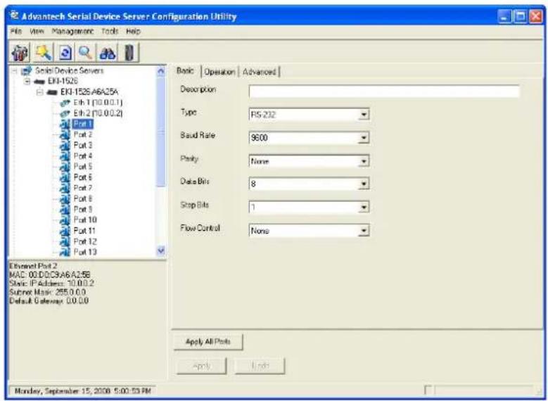
3.4 Serial Settings
This section explains how to configure the EKI-1528/1526 serial communication parameters using this utility. There are various operation modes that are suitable for different application.
Click on the "+" before the model name (e.g. EKI-1526), and the utility will expand the tree structure to show the individual device name. And click on the "+" before the device name, and the utility will expand the interfaces on this device server. Select the serial interface.
■ Description:
You can give a more detailed description on the function of the port for easier management and maintenance. Descriptions have a limit of 128 characters.
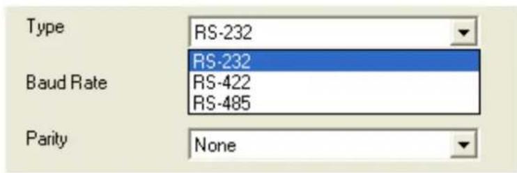
Type
The EKI-1500 serial device server offers three kinds of serial interfaces, RS-232, RS-485 and RS-422. User can use any of the three serial interfaces according to user's requirements.
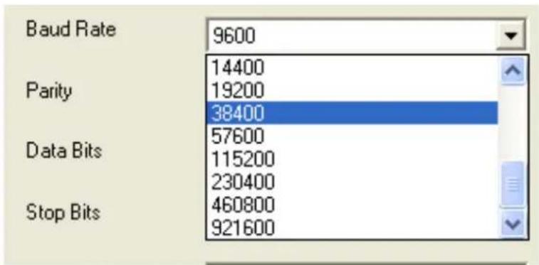
Baud Rate:
The EKI-1500 serial device server supports baud rate from 50 to 921.6Kbps. While setting the baud rate, please note that the value should conform to the current transmission speeds of connected devices.
bar
| Category | Value | |---|---| | Baud Rate | 9600 | | Parity | 14400 | | Parity | 19200 | | Parity | 38400 | | Data Bits | 57600 | | Data Bits | 115200 | | Data Bits | 230400 | | Stop Bits | 460800 | | Stop Bits | 921600 |Parity:
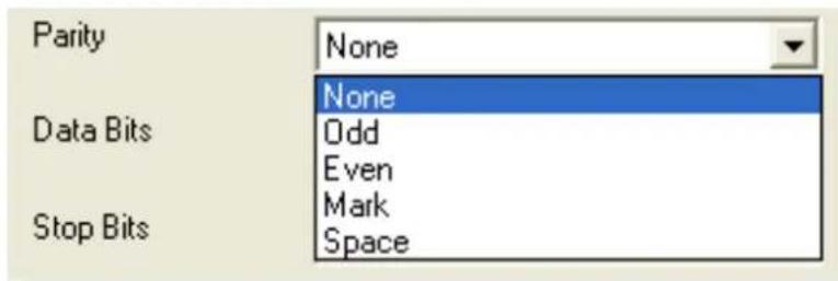
The EKI-1500 serial device server provides five options: None, Odd, Even, Space, and Mark.
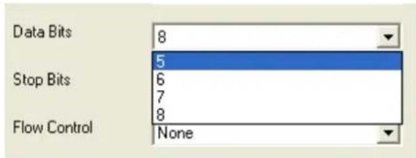
Data Bits:
The EKI-1500 serial device server provides four options: 5, 6, 7 and 8.
- Stop Bits:
The EKI-1500 serial device server provides three options: 1, 1.5 and 2.

Flow Control:
The EKI-1500 serial device server provides four options: None, XOn/XOff, RTS/CTS, and DTR/DSR.

Note!

When you have finished the configuration of these settings for each category, please press the "Apply" button in order to make these settings effective on the Serial Device Server. Or you can press "Apply All Ports" to make these setting effective for all serial ports on the Serial Device Server.
■ Advanced Settings:
The EKI-1500 serial device server provides the advanced settings for some special applications which need critical time requirements. In normal applications, these settings are recommended not to be set to avoid the unusual action happened.
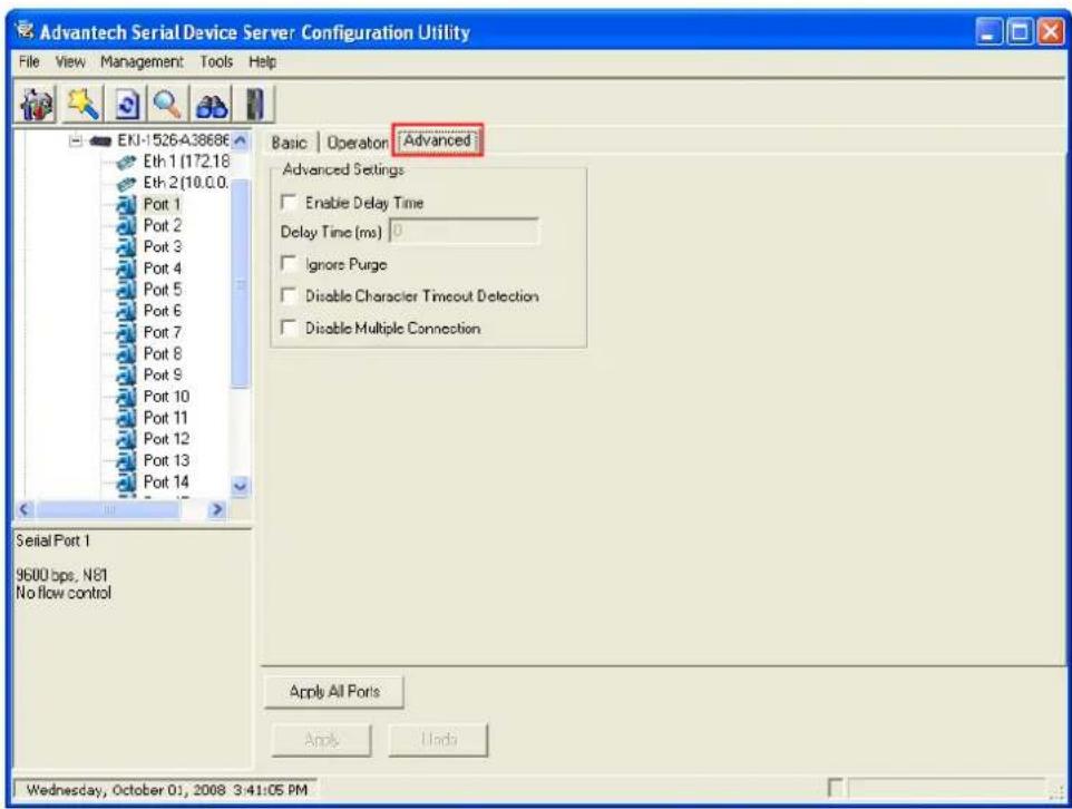
Delay Time (ms)
When you enable the delay time, the serial port will postpone the received data for the time interval you set, and then send the received data to the TCP/IP network.
Ignore Purge
Some application program will purge the serial port while it is the first time opens this serial port. You can ignore the purge command by enable this option.
Disable Character Timeout Detection
Enable this option will disable the serial port character timeout detection.
Disable Multiple Connection
Enable this option will disable the multi-access function, thus the only one TCP connection is allowed on this serial port.
Note! These settings are just for some special application cases. We recommend do not enable the advanced settings in normal usage.

3.5 Operation Mode Settings
3.5.1 Virtual COM Mode
The EKI-1500 serial device server extends traditional COM ports of a PC to Ethernet access. Through Ethernet networking, users can control and monitor remote serial devices and equipments over LAN or WAN. The EKI-1528/1526 comes with a COM port redirector (Virtual COM driver) that transmits all serial signals intact. This means that your existing COM-based software can be preserved, without modifying to fulfill the needs. The Virtual COM mode allows user to continue using RS-232/422/485 serial communications software that was written for pure serial communication applications.
The EKI-1528/1526 comes with COM port redirector (virtual COM driver) that work with Window 2000/XP/Vista(X86) systems. The driver establishes a transparent connection between host and serial device by mapping the IP of the EKI-1500 serial device server serial port to a local COM port on the host computer.
The EKI-1528/1526 provides Multi-access function through Ethernet connection path. Allow the maximum of 5 connections to open one serial port simultaneously. In this mode, all connection has to use the same serial setting. If one serial setting of these connections is different from others, the data communication may operate incorrectly.
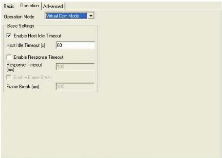
■ Host Idle Timeout
The "Host Idle Timeout" setting monitors the connection between the host and the device. If the "Host Idle Timeout" setting time is reached, the device server will release the resources allocated to the port mapping. This prevents a stalled host from affecting the connective device.
The EKI-1528/1526 provides Multi-access function through Ethernet connection path. Allow the maximum of 5 connections to open one serial port simultaneously. In the mode, all connection has to use the same serial setting. If one serial setting of these connections is different from others, the data communication may operate incorrectly.
There are two operating mode of Multi-access function. One is Normal mode; another is Round-Robin mode.
Normal mode
Disabling "Response Timeout" parameter, the EKI-1528/1526 will operate in "normal mode". When multiple hosts open the serial port simultaneously, the EKI-1528/1526 only offers control ability for the first connected host and provides data communication function for others. Each serial port supports up to five simultaneous connections, so multiple hosts can transmit/receive data to/from the same serial port simultaneously. Every host can transmit data to the same serial port, and the EKI-1528/1526 will also transmit data to every hosts. When the multiple hosts transmit data to the same serial port at the same time, the received data from Ethernet and the outputs of serial port are mixed. When the EKI-1528/1526 receives data from serial port, the data will also be transmitted to the connected hosts simultaneously.
Round-Robin mode:
Enabling “Response Timeout” parameter, the EKI-1528/1526 will operate in “Round-Robin mode”. Each serial port supports up to five simultaneous connections, so multiple hosts can transmit/receive data to/from the same serial port simultaneously. Every host can transmit data to the same serial port simultaneously, but the EKI-1528/1526 will process the data communication in order. The EKI-1528/1526 will process the first host’s request and reply the response to the first host. The EKI-1500 serial device server can determine the end of the serial acknowledgement via response timeout. When EKI-1500 serial device server receives nothing from serial port after the setting of response timeout, the device will reply the acknowledgement to the host and then process the next host’s request. While the connected hosts are more and “Response Timeout” is long, the process time is much longer.
Frame Break is a very import parameter for Round Robin mode. This parameter is the smart way to reduce inefficient waiting time and the EKI-1528/1526 can transmit data more efficiently. Disabling the Frame Break function, the EKI-1528/1526 will wait "Response Timeout" period, whether the device have transmitted the data. During this period, the commands from hosts will be queued and the EKI-1528/1526 just processes this command. Enabling "Frame Break", if the serial port idle is longer than the "Frame Break" period, the EKI-1528/1526 will assume the communication is completed and continue the next host's query. This is an efficient way to reduce the waiting time and improve the performance.
3.5.2 Data Mode (USDG Mode)
The EKI-1528/1526 can be Data server or Data client either. Both operations support TCP and UDP protocol. The EKI-1528/1526 makes your serial devices behave just like networking devices. You can issue commands or transmit data from serial devices, which connected to the EKI-1528/1526, to any devices that are connected to the Internet.
The EKI-1528/1526 allows most 5 host PCs accessing data simultaneously via polling networking architecture. You can use it according to your application. If you want to access the EKI-1528/1526, you must ascertain your application software supports standard networking application programming interface (API) such as: WinSock Socket.
You might select "USDG Mode" as the following figure to change the mode of the port to TCP server/client or UDP mode.
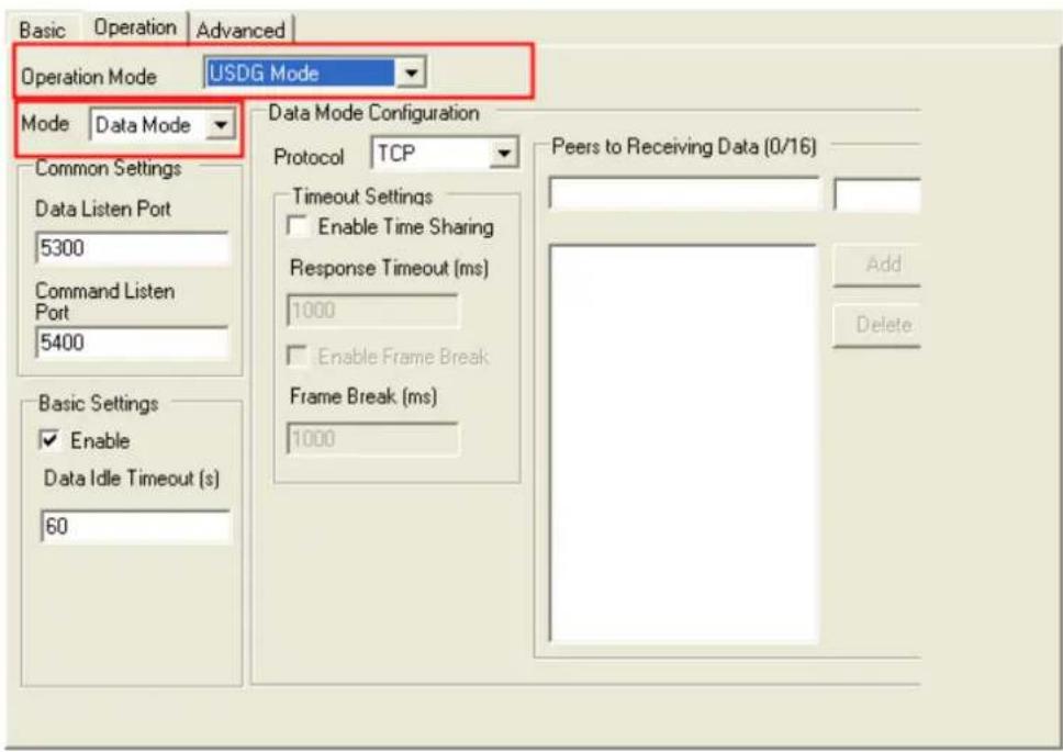
Protocol
The EKI-1528/1526 provides TCP/IP and UDP two protocols. In settings, you can choose either TCP mode or UDP mode according to your application.
Data Listen Port
The TCP/UDP port number represents the source port number, and the number is used to identify the channel for remote initiating connections. Range: 1024-65533. If an unknown caller wants to connect to the system and asks for some services, they need to define the TCP/UDP port to carry a long-term conversation.
Each node on a TCP/IP network has an IP address, and each IP address can allow connections on one or more TCP port. The well known TCP ports are those that have been defined; for example, port 23 is used for Telnet connections. There are also custom sockets that users and developers define for their specific needs. The default TCP/UDP port of the EKI-1528/1526 is 5300. The example initial 5300 is System Port, and 5301 is Data Port. But users can adjust them by one's preference or application.
Each port has its own data listen port to accept connected request of other network device. So, the data listen port can't be set the same value. You can transmit/receive data to/from device via the data listen port.
Command Listen Port
Each port has its own command listen port to accept connected request of other network device. So, the command listen port can't be set the same value. You can use 'AT command' to change the port setting via the command listen port. The Command Listen Port should be different from the Data Listen port.
Data Idle Timeout
The default is 60 seconds. If you want to keep connection continually, you can disable the Data Idle Timeout. Data idle Time is the time period in which the device waits for data. If the EKI-1528/1526 does not receive data over an established idle time, the EKI-1528/1526 will disconnect temporarily. When the data comes to the EKI-1528/1526, it will reconnect automatically. Users do not need to reconnect.
Enable Time Sharing
The EKI-1528/1526 provides Multi-access function through Ethernet connection path. Allow the maximum of 5 connections to open one serial port simultaneously. In the mode, all connection has to use the same serial setting. If one serial setting of these connections is different from others, the data communication may operate incorrectly.
There are two operating mode of Multi-access function. One is Normal mode; another is Round-Robin mode.
Normal Mode
Disabling “Response Timeout” parameter, the EKI-1528/1526 will operate in “normal mode”. When multiple hosts open the serial port simultaneously, the EKI-1528/1526 only offers control ability for the first connected host and provides data communication function for others. Each serial port supports up to five simultaneous connections, so multiple hosts can transmit/receive data to/from the same serial port simultaneously. Every host can transmit data to the same serial port, and the EKI-1528/1526 will also transmit data to every hosts. When the multiple hosts transmit data to the same serial port at the same time, the received data from Ethernet and the outputs of serial port are mixed. When the EKI-1528/1526 receives data from serial port, the data will also be transmitted to the connected hosts simultaneously.
Round-Robin Mode
Enabling “Response Timeout” parameter, the EKI-1528/1526 will operate in “Round-Robin mode”. Each serial port supports up to five simultaneous connections, so multiple hosts can transmit/receive data to/from the same serial port simultaneously. Every host can transmit data to the same serial port simultaneously, but the EKI-1528/1526 will process the data communication in order. The EKI-1528/1526 will process the first host’s request and reply the response to the first host. The EKI-1500 serial device server can determine the end of the serial acknowledgement via response timeout. When EKI-1500 serial device server receives nothing from serial port after the setting of response timeout, the device will reply the acknowledgement to the host and then process the next host’s request. While the connected hosts are more and “Response Timeout” is long, the process time is much longer.
Frame Break is a very import parameter for Round Robin mode. This parameter is the smart way to reduce inefficient waiting time and the EKI-1528/1526 can transmit data more efficiently. Disabling the Frame Break function, the EKI-1528/1526 will wait "Response Timeout" period, whether the device have transmitted the data. During this period, the commands from hosts will be queued and the EKI-1528/1526 just processes this command. Enabling "Frame Break", if the serial port idle is longer than the "Frame Break" period, the EKI-1528/1526 will assume the communication is completed and continue the next host's query. This is an efficient way to reduce the waiting time and improve the performance.
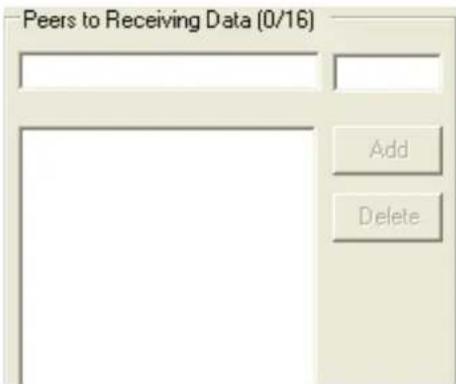
Peer Number
Set the number of network device which you want to connect. You can set maximum sixteen network devices which you want to connect. You need to fill out the IP Address and Port of network devices which you want to connect.
3.5.3 Control Mode (USDG Mode)
In controlling mode, the EKI-1528/1526 presents a modem interface to the attached serial device: it accepts AT-style modem commands to connect / disconnect to other networking device. If you want serial device running application program to connect/disconnect to different devices dynamically, you can use controlling mode.
The “Control mode” provides three kinds of modem AT-style commands. The serial devices can use these commands to control the EKI-1528/1526 to connect/disconnect to remote networking device. Thus, intelligent serial devices such as standalone PLC will send /receive data to/from devices one by one via Ethernet.
Please refer to the Data Mode (USDG Mode) to setup the Data Listen Port, Command Listen Port, and Data Idle Timeout.
Hangup Character
The default character is "+". After you have connected to another serial device via EKI-1528/1526, you may need to disconnect. Then you can use the command "+++" to disconnect. To do this leaves your keyboard idle (don't press any keys) for at least several seconds, then press "+" three times. You can set "Guard Time" to define the idle time. Be sure that you have to press "+" over the idle time.
Guard Time
The default value is 1000 ms.
Example:
The following commands are available for EKI-1528/1526.
Table 3.1: AT Command List
| Command Function | |
| ATDT<TCP port> | “Forms a TCP connection to the specified host.Ex: ATDT 192.0.55.22:5201In above example, the EKI serial device server forms a raw TCP connection to the networking device (192.0.55.22). The TCP port is 5301.” |
| ATA Answering an incoming call | |
| +++Returns the user to the command prompt whenentered from the serial port during a remote host con- nection. | |
3.6 Accessible IP Settings
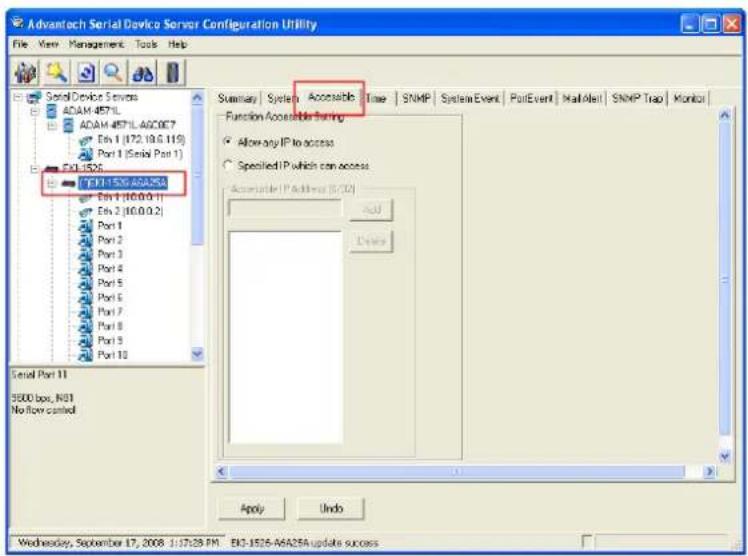
Accessible IP setting allows you to add or remove the blocking host IP addresses to prevent unauthorized access. If you want to restrict access to certain PCs, you can list their IP addresses in this area. The maximum is 32 PCs.
3.7 Auto Warning Settings
3.7.1 Email Alert
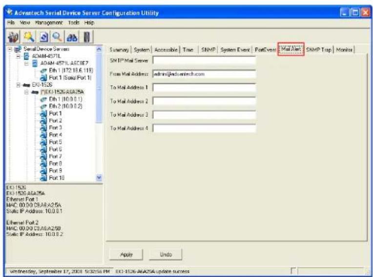
Consult your ISP or Network Administrator for the proper SMTP mail server settings. The auto warning functions may not work properly without proper settings.
3.7.2 SNMP Trap
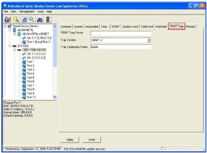
You need to set the proper IP address of SNMP Trap Server. And choose the Trap Version; there are "SNMP v1" and "SNMP v2c" options.
3.7.3 System Event
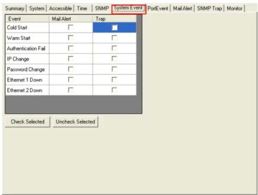
Cold Start
This refers to starting the system from power off. When performing a cold start, the EKI-1528/1526 will send an e-mail, or send a SNMP trap after success rebooting.
Warm Start
This refers to restarting the system without turning the power off. When performing a warm start, the EKI-1528/1526 will send an e-mail, or send a SNMP trap after restarting the system.
Authentication failure
The user types a wrong password from Console or Administrator. When authentication failure
Occurs, the EKI-1528/1526 will send an e-mail, or send a SNMP trap.
IP Change
The user changes the EKI-1528/1526's IP address. When the IP address changes, the EKI-1528/1526 will send an e-mail, or send a SNMP trap after restarting the system.
Password Change
The user changes the EKI-1528/1526's password. When the password changes, the EKI-1528/1526 will send an e-mail, or send a SNMP trap after restarting the system.
Ethernet 1 Down
The Ethernet 1 port has link failure condition. When the Ethernet 1 links fail, the EKI-1528/1526 will send an e-mail, or send a SNMP trap immediately.
Ethernet 2 Down
The Ethernet 2 port has link failure condition. When the Ethernet 2 links fail, the EKI-1528/1526 will send an e-mail, or send a SNMP trap immediately.
3.7.4 Serial Port Event
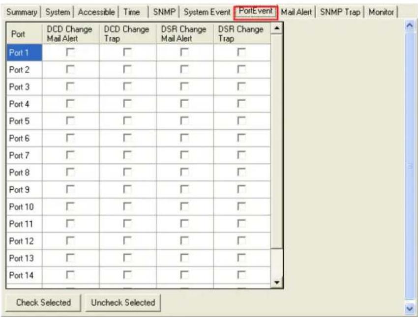
DCD Change
The DCD (Data Carrier Detect) signal has changed, also indicating that the modem connection status has changed. For example, a DCD change to high also means "Connected" between local modem and remote modem. If the DCD signal changes to low, it also means that the connection line is down. When the DCD signal changes, the EKI-1528/1526 will send an e-mail, or send a SNMP trap.
DSR Change
The DSR (Data Set Ready) signal has changed, also indicating that the data communication equipment's power is off. For example, a DSR change to high also means that the DCE is powered ON. If the DSR signal changes to low, it also means that the DCE is powered off. When the DSR signal changes, the EKI-1528/1526 will send an e-mail, or send a SNMP trap.
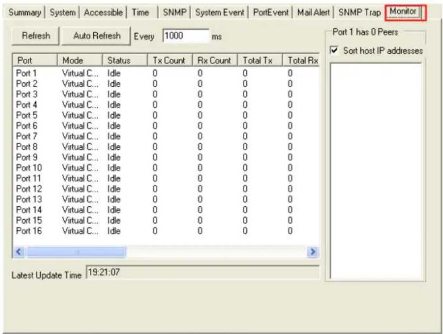
3.8 Port Monitor
Configuration utility provides an excellent function that allows monitoring the serial ports' status. It will present each serial port's operation mode and status. The IP address of the host PC which is communicating with serial port will be list on the right window. Click "Refresh" button, the status will be refresh once. It will be auto refresh after click "Auto Refresh" and the time duration is depending on the setting (the default value is 1000ms).
3.9 Administrator Settings
The configuration utility provides several administrator settings for easy management and configuration. Right click the mouse on the device name in the sub-tree of Serial Device Sever List Area, and select these administrator settings.
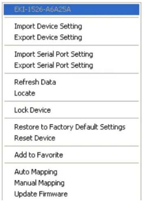
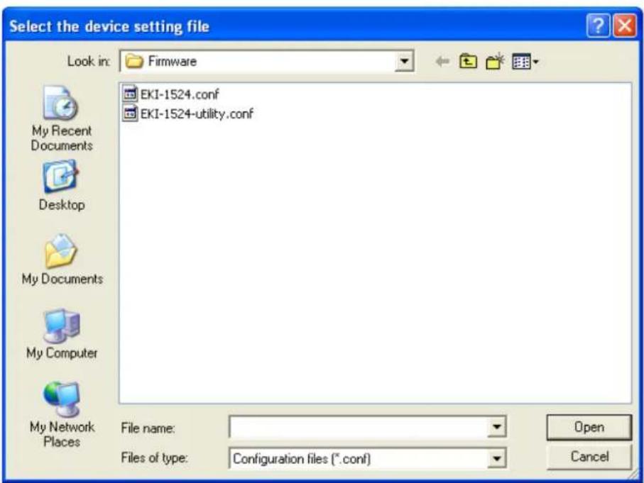
3.9.1 Import/Export Device Setting
The utility allows importing or exporting the serial device server's setting via the ".conf" file format.
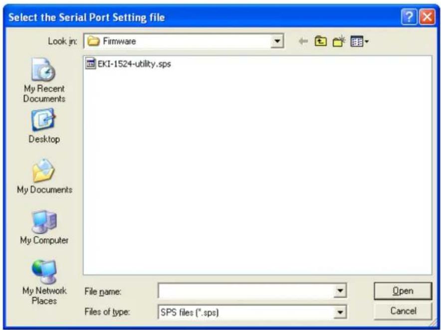
3.9.2 Import/Export Serial Port Setting
The utility allows importing or exporting the serial port setting including "Basic Setting" and "Operation Setting" via ".sps" file format.
3.9.3 Locate the Serial Device Server
If there are many serial device severs need your management, you may need to identify which unit is correct to configuration on utility. Click "Locate" to make that unit's "Status" LED be steady on and the buzzer will make the beep sound until you click "Stop Locate".
3.9.4 Lock the Serial Device Server (Password Protection)
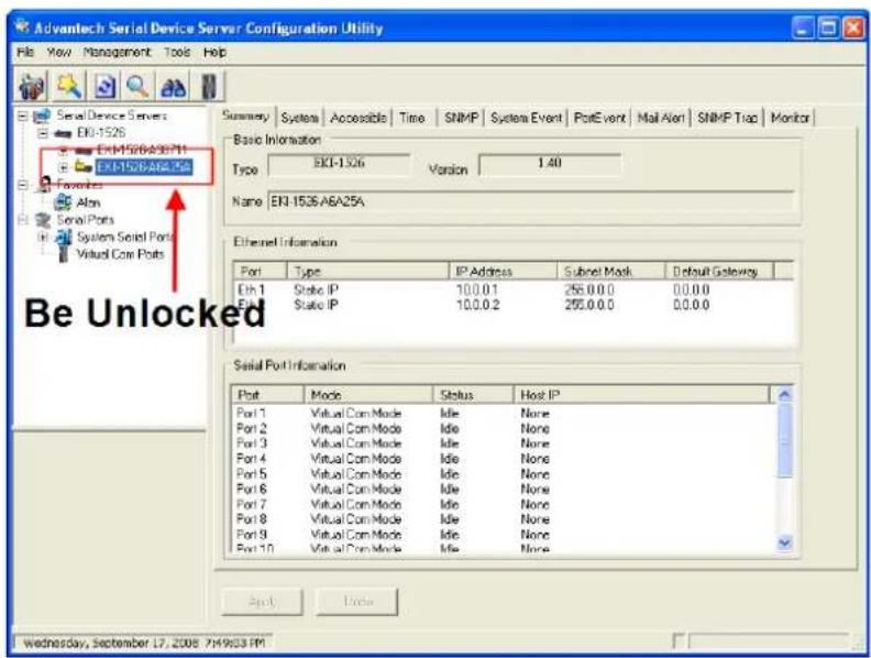
The configuration utility provides the "Lock Device" function to make it more confidential. You need to set up a password while the first time clicking "Lock Device". Be sure to click "Reset Device" to restart the serial device server and store your setting password into the memory.
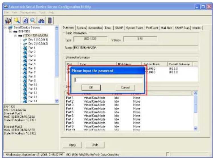
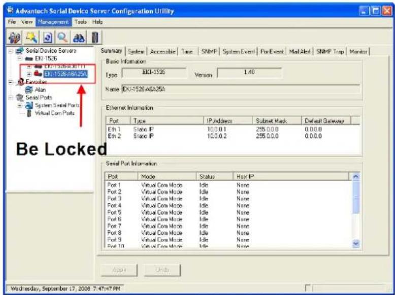
Click "Unlock Device" to unlock the serial device sever, and you need to fill in the password you have set up before. If you forgot the password, the only way to solve this problem is to restore the setting of the serial device server to the factory default which will be introduced next section.
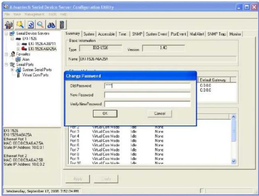
If you want to disable this function or change the password, click "Change Password" to change the password to default "None" (leave the new password and confirm new password columns blank) to disable this function or other password you want to change. Be sure to click "Reset Device" to restart the serial device sever and store the new password into the memory.
3.9.5 Restore to Factory Default Settings
The configuration utility provides this function to let you can restore the serial device server to factory default settings. The confirm message will be pop-up while clicking "Restore to Factory Default Settings". If you really want to restore the serial device sever to factory default settings, please click "Yes" button to continue.

Then, please power off the serial device server within ten seconds, after reconnecting the power back, the all setting will be reset to the factory default. If the power remains more than ten seconds, the serial device server will not have any changes.

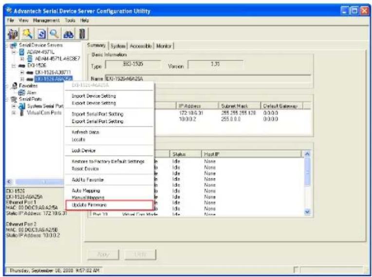
3.9.6 Update Firmware
Advantech continually upgrades its firmware to keep up with the ever-expending world of computing. You can use the update firmware function in the utility to carry out the upgrade procedure. Please access Advantech's website: http://www.advantech.com to download the latest version of the firmware. Before update the firmware, make sure that your host's Network domain is as same as the serial device server or the host can establish the TCP connection to the serial device server.
Right Click on the device name and select "Update Firmware" function.
Select the firmware file you want to update.
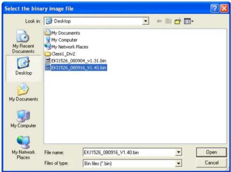
Wait for few seconds to process the updating firmware. After downloading the firmware completely, click on the "OK" button. The serial device server will restart automatically.
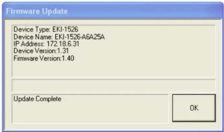
Note! Be sure that the host PC Ethernet network domain is as same as the EKI-1500 serial device server or the host PC can establish the TCP connection with the serial device server while doing the updating firmware process.
Chapter 4
Setting COM Redirector
4.1 Setting COM Redirector(Virtual COM port)
Advantech COM port mapping software is a serial COM port redirector that creates virtual COM ports and provides access to serial devices connected to Advantech serial device servers. Your serial device applications can communicate with serial devices connected to Advantech serial device servers without software changes. Since the virtual COM ports work like standard Windows COM ports, your application software sees no difference between a local serial device and one connected to a Advantech serial device server.
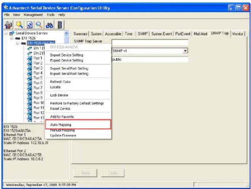
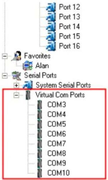
COM redirector utility and Virtual COM port Management utility are integrated into one utility with same GUI. Advantech Serial Device Server Configuration Utility can create all Virtual COM ports using "Auto Mapping" function. You can map the Virtual COM port by yourself.
4.1.1 Auto Mapping
Right click the serial device name on the sub-tree of Serial Device Server List area and select the "Auto Mapping" function.
The serial ports that can be assigned to virtual COM will be shown in this window. Select the serial ports you wish to map or click the
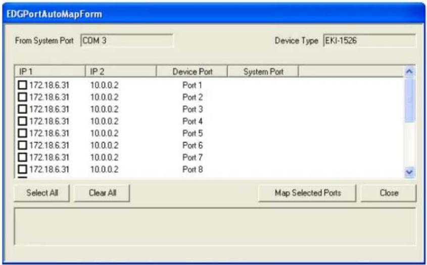
The COM ports in the "Virtual Com Ports" listing are now available for use by Windows applications.
Right click the serial device name on the sub-tree of Device Server List area and select the "Manual Mapping" function.
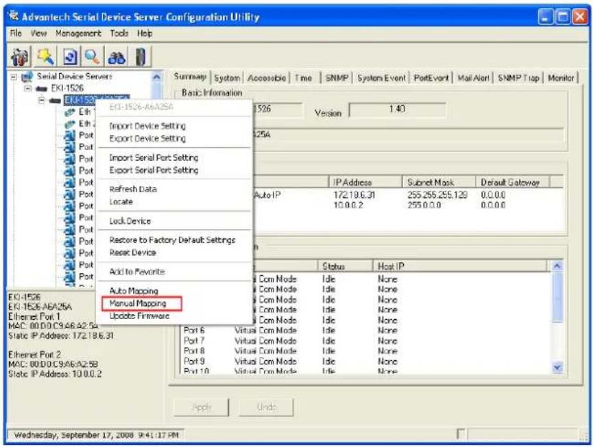
Select the serial port on the serial device server and the host COM that you want to map. Press
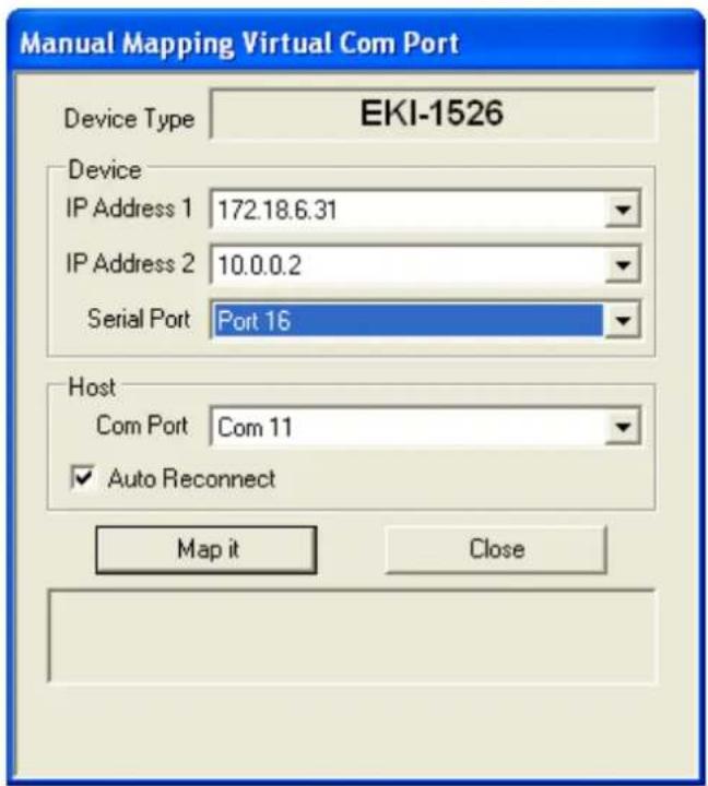
Auto Reconnect Property
Sometimes, the connection between Advantech serial device server and HOST is interrupted by network traffic or powered-off by accident. In such a situation, the host has to reconnect to Advantech serial device server. The function "Auto Reconnect" is for this purpose, if the Advantech serial server loses the connection to its host, the COM redirector will try to re-establish the connection while the host's AP access the virtual COM port. The COM redirector DOES NOT re-establish the connection automatically. When the connection is working again, the host's commands will be automatically received by the Advantech serial device server again. Reconfiguration is not necessary, so this function enhances the reliability of the system.
If the function is disabled, the connection does not be re-established again unless the COM redirector or host is restarted.
Dual Ethernet Redundancy
The EKI-1500 serial device sever has two Ethernet ports. You can select two Ethernet port to establish two Ethernet connections with one virtual COM port. It means that COM redirector will use one connection with the COM port on device server to communicate. If this connection failed, COM redirector will establish another Ethernet connection to communicate with device. The switch time will be 3 seconds \~ 5 seconds depending on the network traffic and host status.
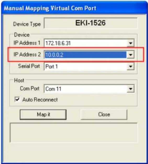
If you don't use the redundant function, just select the correct IP address in the IP address 1 field.
Note! If you set the wrong IP address, COM redirector will still try to connect the device. It might cause the system performance low or other issue.

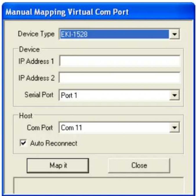
4.1.3 Manual Direct Mapping Virtual COM Port
Click the button on the Quick Took bar, you can add a target by selecting the
Device Type and inputting the IP address without physically connecting the serial device server to the network.
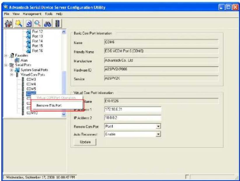
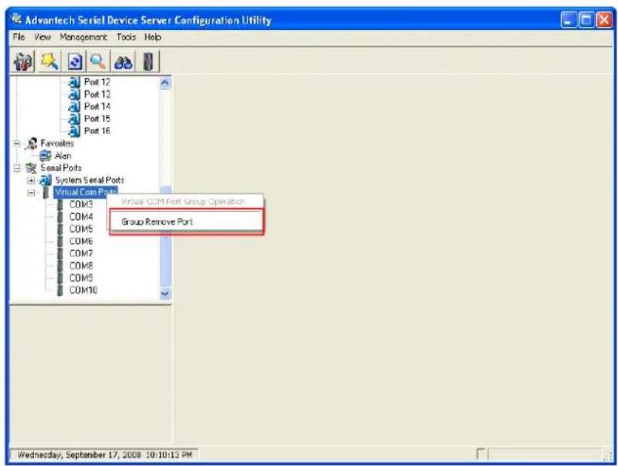
4.1.4 Remove the Virtual COM Port
If you want to remove the virtual COM port, you can remove them one by one or group remove ports.
Individual Remove
Right click on COM port you have mapped before and select "Remove This Port".
Group Remove Port
Right click on Virtual Com Ports on Device Server List Area and select "Group Remove Port", you can choose which ports you want to remove.
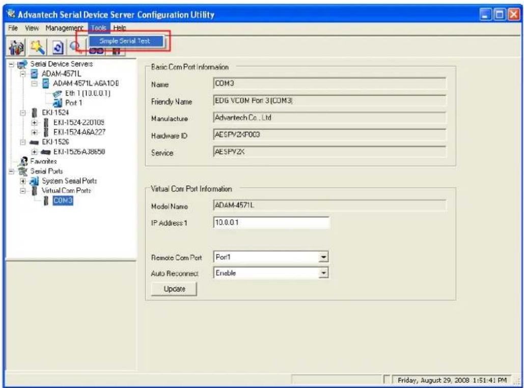
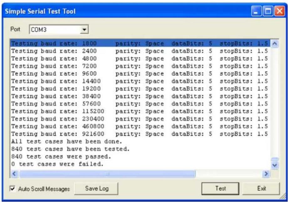
4.2 Running Diagnostic Test
The purpose of this test is to make sure the communication from host PC to serial device server is OK. If there is still an error, you can check the communication from the EKI-1500 serial device server to the devices.
If the test is selected, an external test will be done to check that the connection signals for each port are working properly. For the test, you will need to connect each port to a loopback tester (provided in the package). The loopback test only applies to RS-232 mode. The test is divided into two parts: Signal test and Communication Parameters test.
Note! Before you do this diagnostic test, you must complete the process of virtual COM port mapping (which is described in chapter 4.1).

Click "Simple Serial Test" on the Tools menu,
Select which COM port you want to run diagnostic test, and then press "Test" button to process the testing.
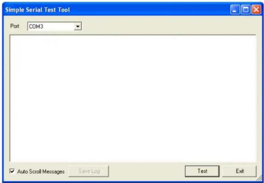
Signal Test
■ RTS -> CTS: check the RTS and CTS signal between two ports
■ DTR -> RI: check the DTR and RI signal between two ports
■ DTR -> DSR: check the DTR and DSR signal between two ports
■ DTR -> DCD: check the DTR and DCD signal between two ports
Communication Parameters Test
■ Baud rate: 50bps \~ 921.6kbps
Data bit: 5, 6, 7, 8
■ Stop bit: 1, 1.5, 2
■ Parity: Odd, Even, None, Space, Mark
When the test is finish, it will show the test result, the click "Exit" button to return to the utility window.
Chapter 5
Web-Based Configuration
5.1 Overview
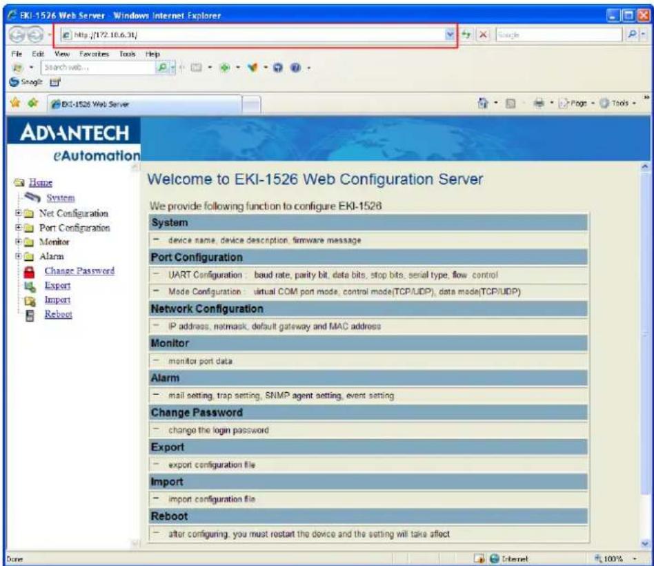
EKI-1500 serial device server can be configured through a web interface. By using a standard web browser, the same procedure as with the Windows configuration utility can be used. In the browser's address field, enter the IP Address of your EKI-1500 serial device server. The default IP setting is 10.0.0.1, but you should use the IP which you have previously assigned for this device. Once the IP is entered, you will be presented with the following windows.
Note! Before using the web-based configuration, make sure your host PC Ethernet network IP domain is as same as the serial device server, or it can establish the TCP connection with the serial device server.
5.2 Accessing the Web Page
By configuration utility
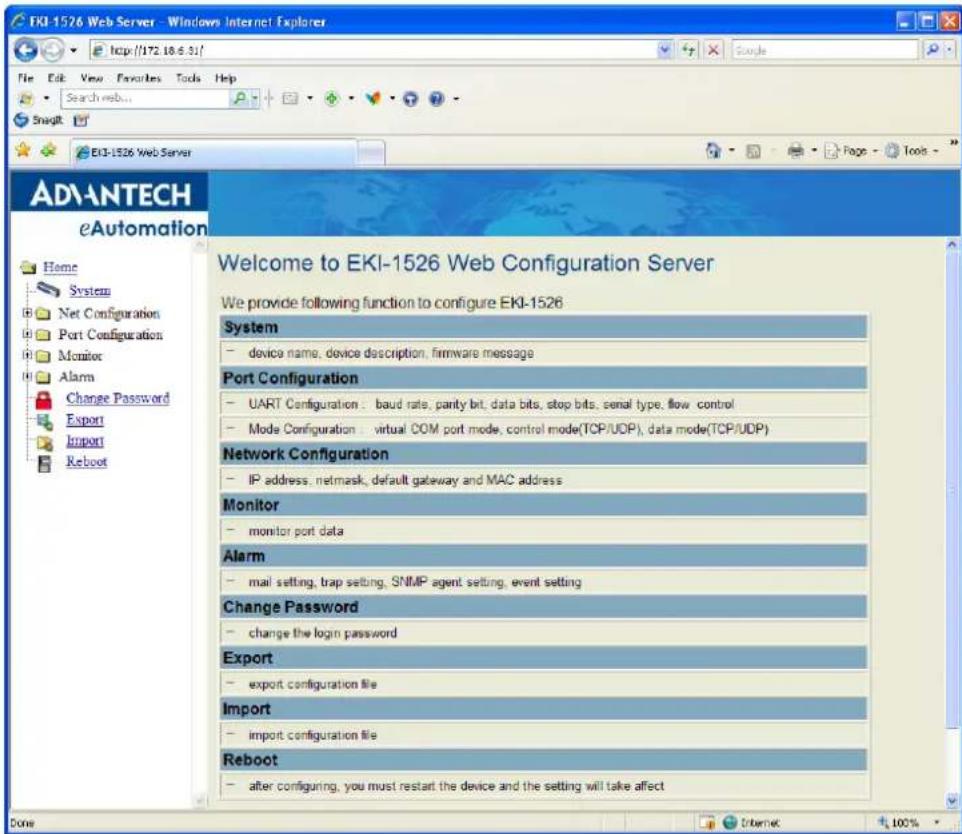
By Windows Internet Explorer
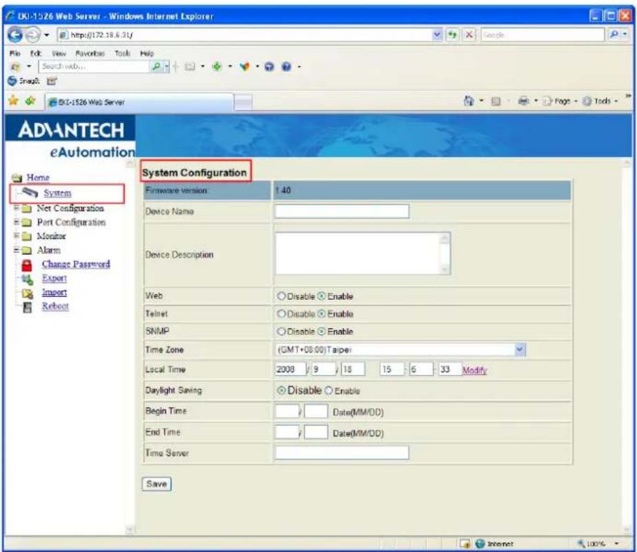
5.3 System
You can change the Device Name and Device Description on this page. You can also enable or disable the Web, Telnet, and SNMP functions. Moreover, you can set the Timezone related setting.
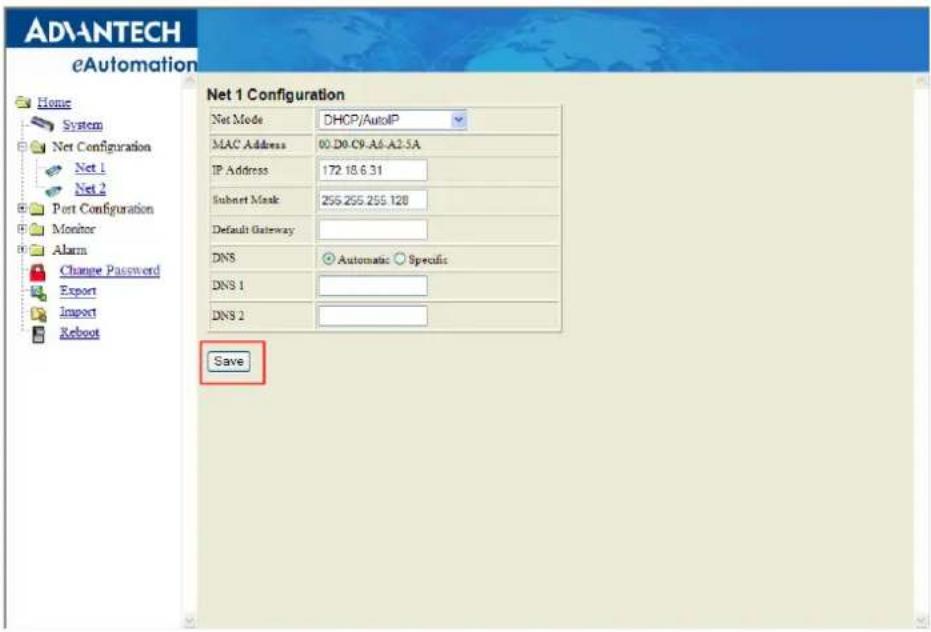
5.4 Network Configuration
Click the Net Configuration and chose either Net 1 or Net 2, there are Net Mode, IP Address, Subnet Mask, Default Gateway and DNS. Enter the corresponding values for your network environment. Remember press "Save" after fill in all values.
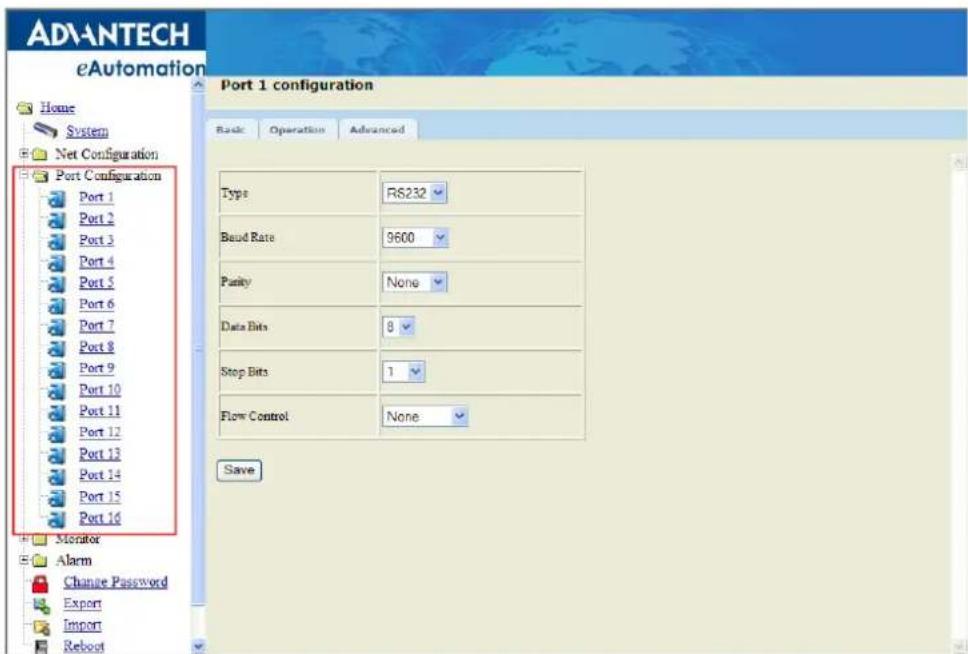
5.5 Port Configuration
There are Basic, Operation Mode, and Advanced Setting in the serial port configuration. For more detailed information for setting, please refer to chapter 3.4 and chapter 3.5.
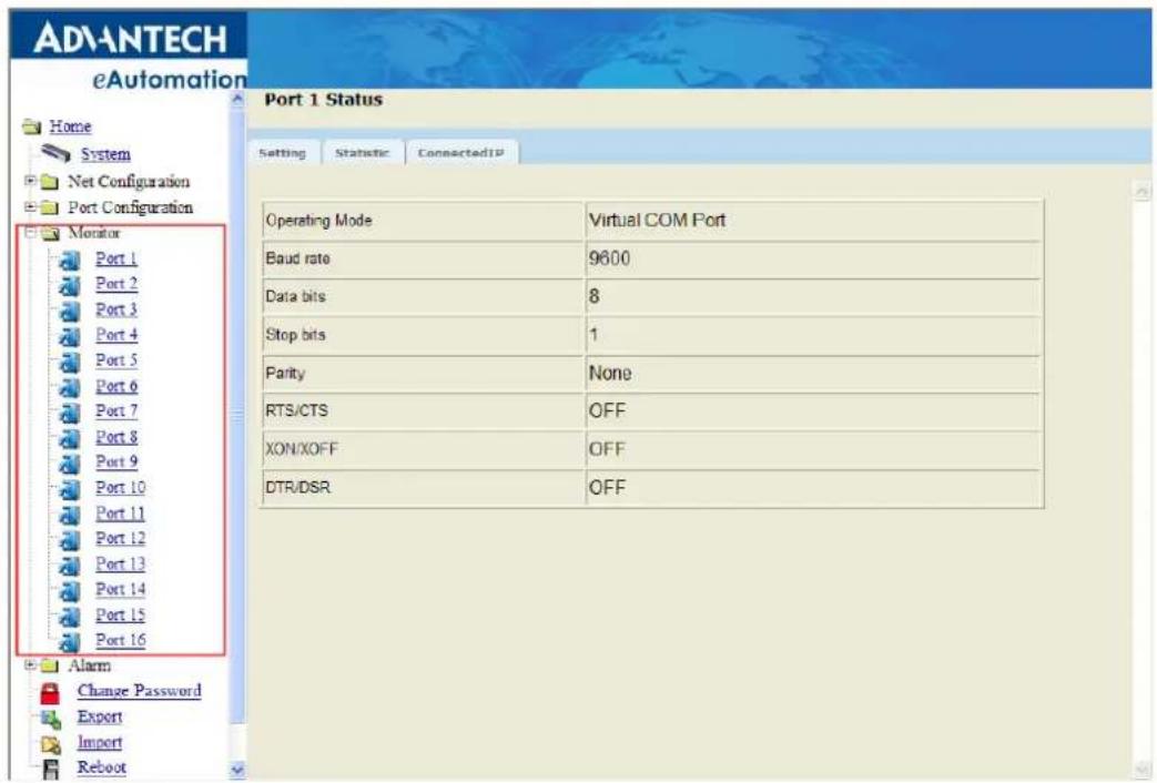
5.6 Monitor
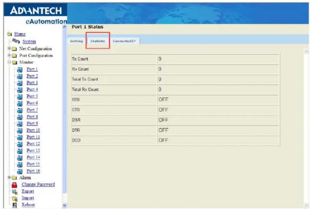
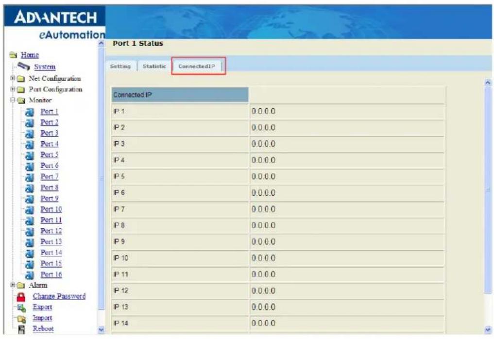
You can monitor the serial ports settings, statistic, and the connected IP address by click on Monitor function on the main menu.
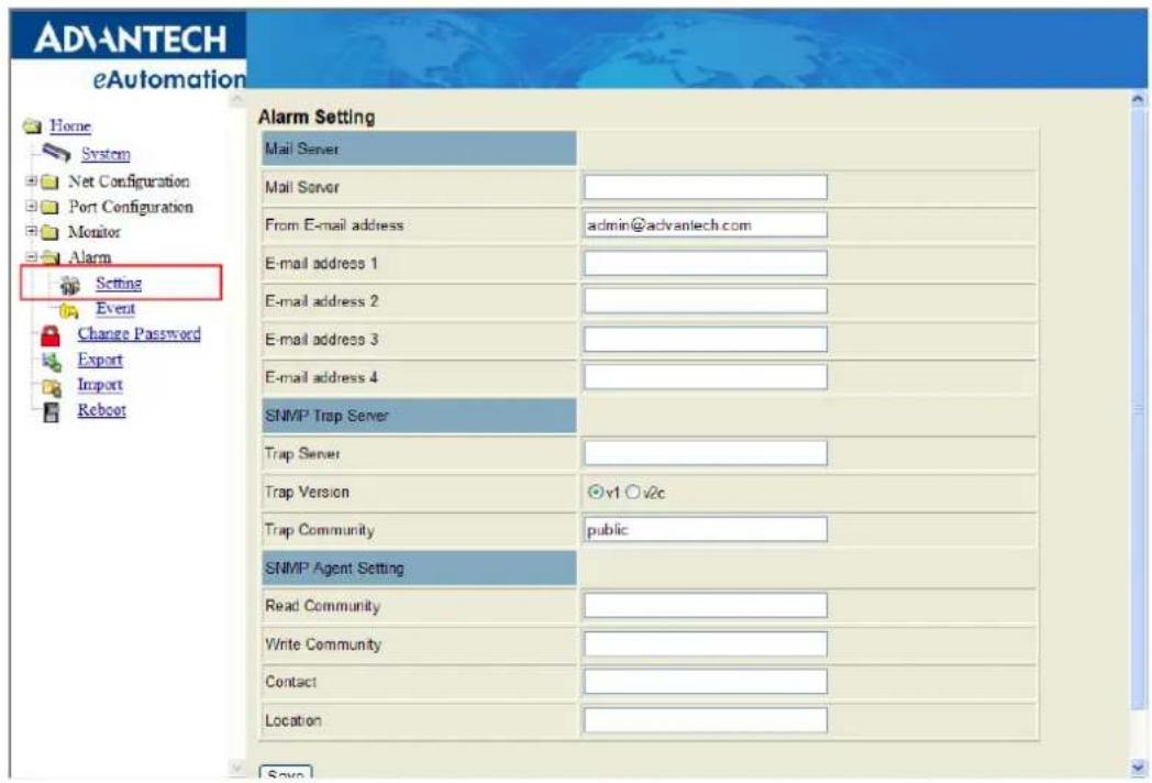
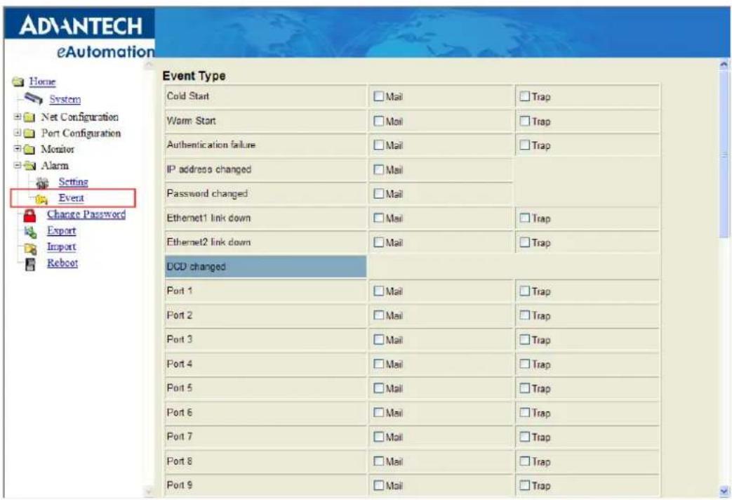
5.7 Auto Warning (Alarm)
You can set the e-mail server and SNMP Trap server in the Setting page, and set the event type in the Event page. For more detailed information for Auto Warning function, please refer to chapter 3.7.
Note! All new configurations will take effect after rebooting. The reboot function is located on the main menu of the Web Configuration.

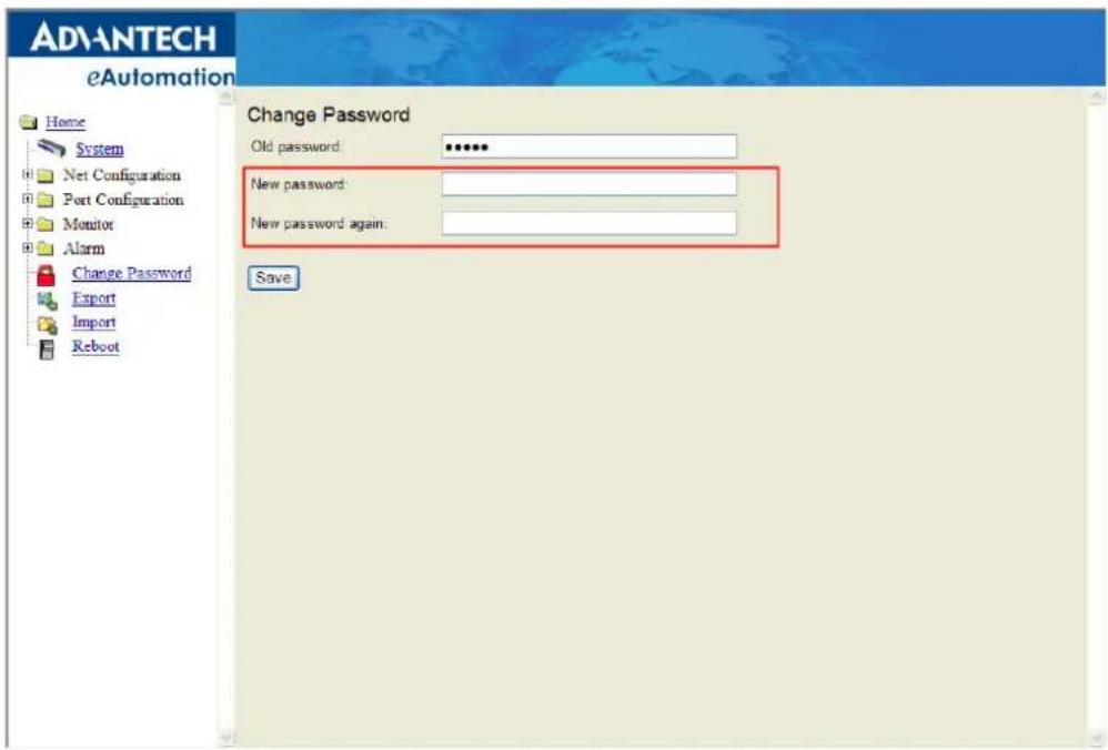
5.8 Change Password
You can change the serial device server password on here:
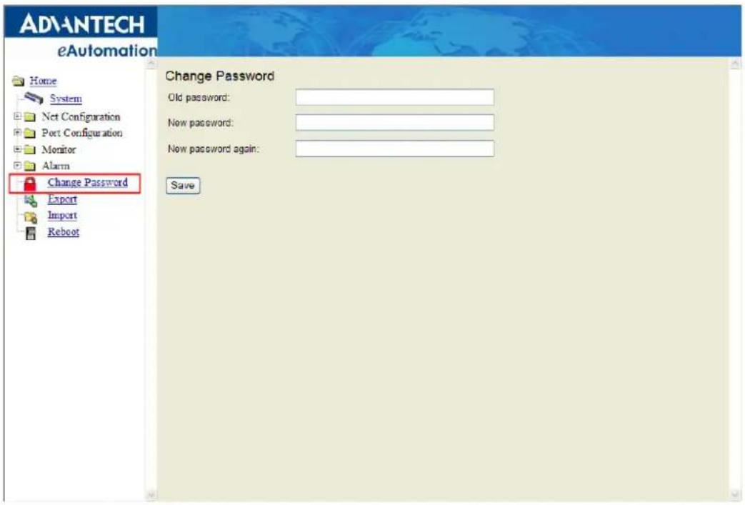
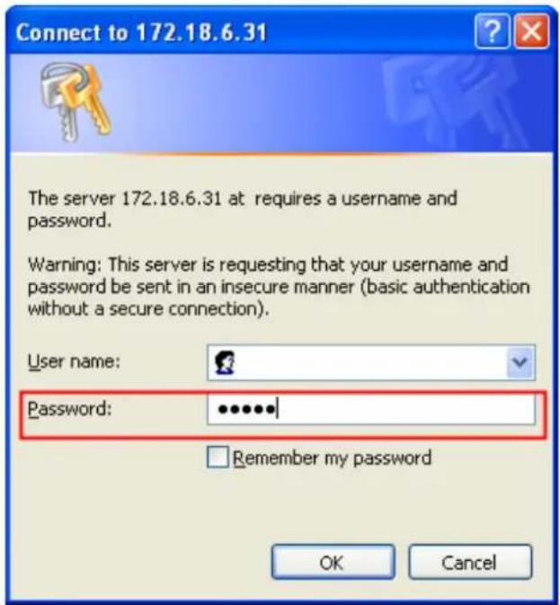
If you have set a password via the configuration utility or Telnet or serial console, when you access the web configuration, you need to key in the password. Do not need to enter the username in the dialog.
If you want to disable the password protection, just change the password to the default "None" (leave the new password column blank), Be sure to press the "Save" button and reboot the serial device server to make the change effective.
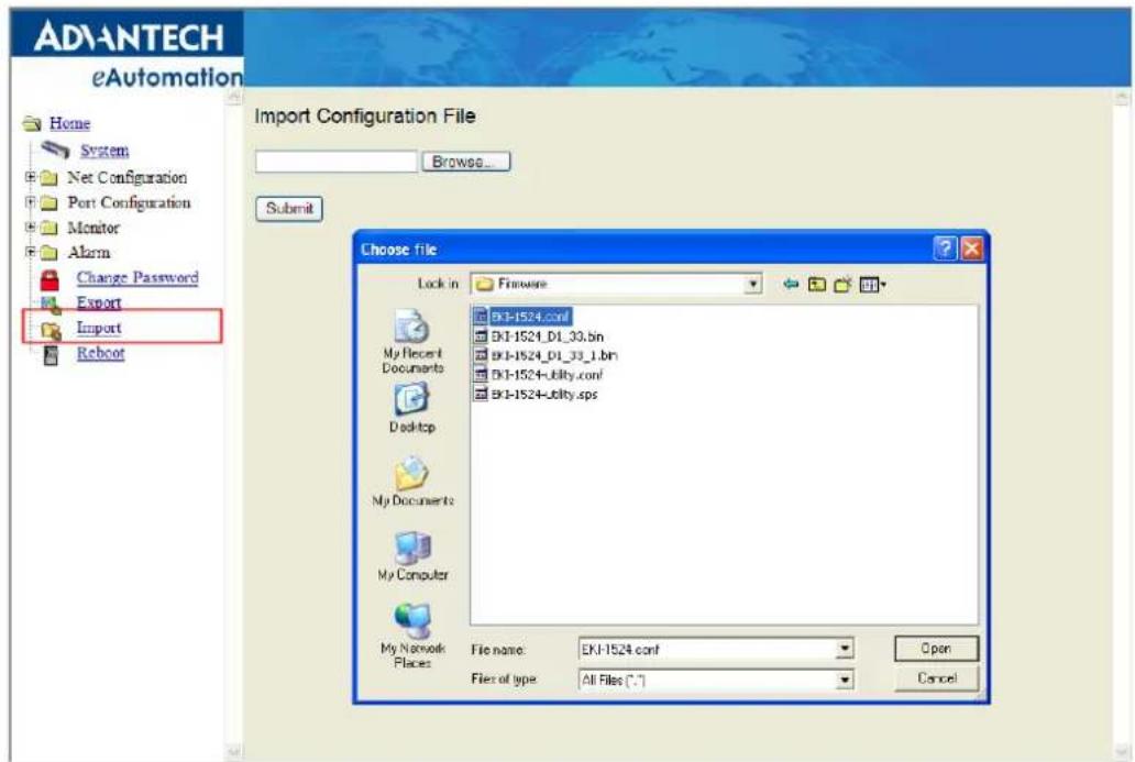
5.9 Import/Export Device Settings
You can Import or Export the serial device server all setting as the “.conf” file format.

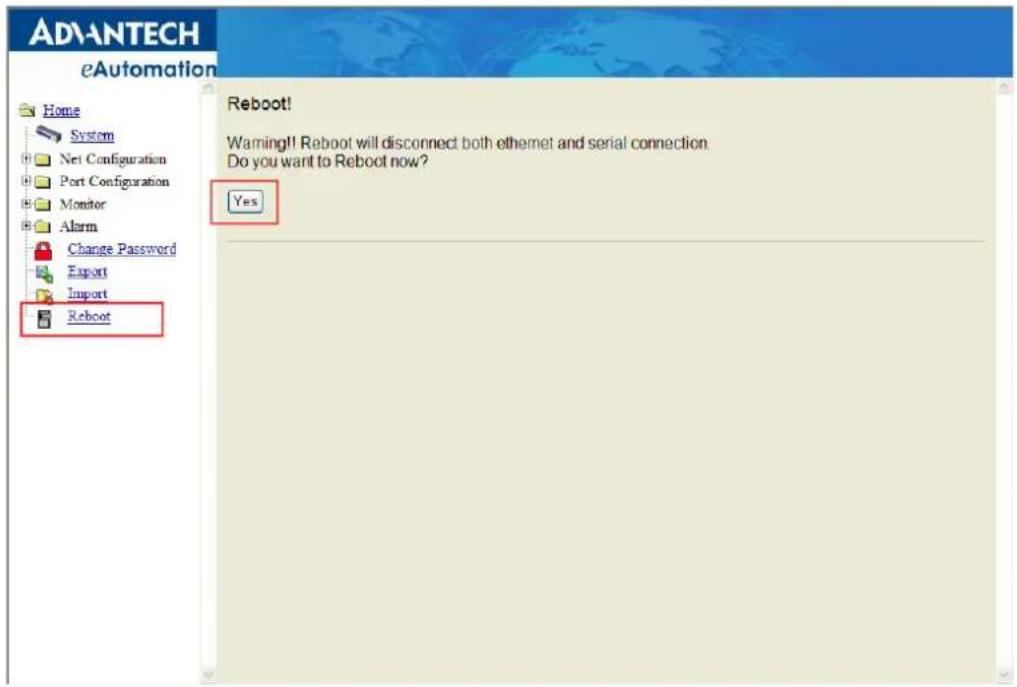
5.10 Reboot
The configuration will take effect after clicking "Save" button. But all configurations will save to flash memory after this reboot step. Press the "Reboot" button and the system will give a reset response. It will take a few seconds to reconnect with the new values.
Chapter 6
Telnet/Serial Console Configuration
6.1 Overview
The purpose of the Console Configuration is to help you manage your device in console mode. One of the main functions of the console mode is to change the web configuration login password. You can use terminal software like Hyper Terminal, Telix and other related terminal software.
6.2 Telnet Console
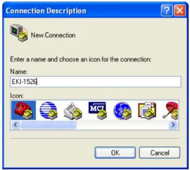
Create a new connection
You can create a new Telnet connection and assign a connection name for the console configuration.
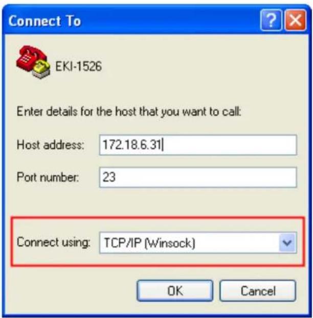
Input the IP address
Confirm that the Telnet console configuration works ok. Be sure that your host PC Ethernet network IP domain is as same as the EKI-1500 serial device server, and the Telnet TCP port number is "23".
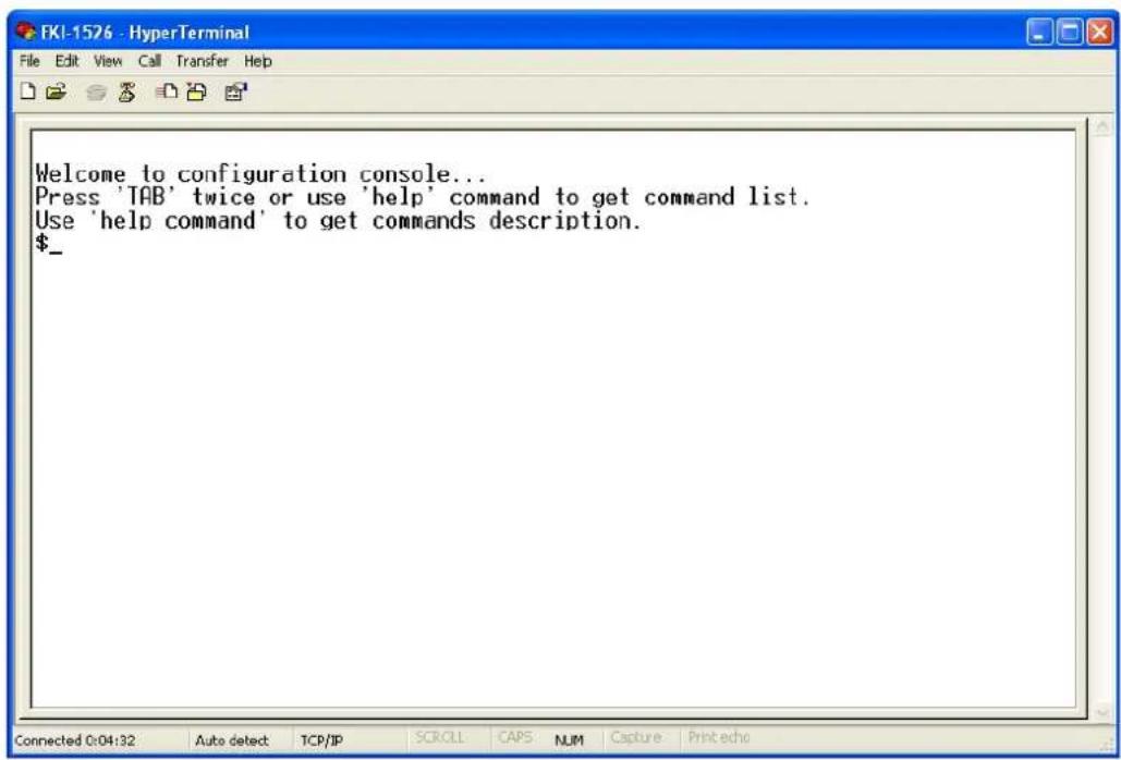
Connecting Success
After connection the serial device server in Telnet console mode, you can see the welcome message in the Hyper Terminal Windows.
6.3 Serial Console
Connecting the cable
You can connect to the EKI-1500 serial device server's console port with a RS-232 DB9 M-type communication cable, with the other end connecting to the host's serial port. Make sure the connection is OK and then run the Hyper Terminal Program on your host.
Create a new connection
You can create a new connection and assign a connection name for the console configuration.

Select the COM port
Confirm that the console configuration works ok.

COM Port Settings
To connect the EKI-1500 serial device server for console configuration, the port setting should match the EKI-1500 serial device sever default settings.

Console Configuration Default Settings
Baud rate: 38400
Data bits: 8
Parity: None
Stop bits: 1
Flow control: None
Connection Success
After connecting the device in console mode, you can simply press
6.4 Command List
Table 6.1: Console Command List
| Command Function Description | |
| system Show or configure the system information | |
| port Show or configure the serial ports information | |
| portadv Show or configure the serial ports advanced settings | |
| mvcom Show or configure the serial ports in Virtual COM mode | |
| mctrl Show or configure the serial ports in Control mode (USDG) | |
| mdata Show or configure the serial ports in Data mode (USDG) | |
| net Show or configure the Ethernet ports settings | |
| password Set or change the password | |
| apply Write settings to the flash memory and reboot the system immediately | |
| exit Terminate the shell session | |
| help Display help information of command list | |
| Display help information of command list | |
| import Import the serial device server all settings | |
| export Export the serial device server all settings | |
| monitor Monitor the serial ports status | |
| alarm | Show or configure the auto warning functions including mail alarm and SNMP alarm |
| time Show or configure the time information | |
| service Enable or disable the web, Telnet and SNMP functions | |
Help
You might type the "help" command or press
[Usage] help
[Function] Display help information of command list
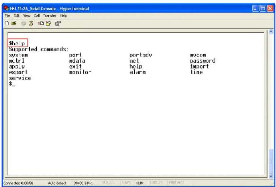
You might use "help" command to show the usage of all commands.
[Usage] help [command]
[Function] Show the usage of command
![$help Supported commands: system port portadv mvcom mctrl mdata net password apply exit help import export monitor alarm time service $help system Usage: system Show current device status and informations. Usage: system name [Maximum length 31 bytes] Set current device name. Usage: system desc [Maximum length 127 bytes] Set current device description. $_](/content/2026/06/1194515/images/a0e64be5f283b642633374ec313ecf85b162dd047896fa23a812ad7b6744165f.jpg)
System
[Usage] system
[Function] Show firmware version, device name and description
![$system Firmware Version :1.40 Device Name :'EKI-00D0C9A6A25A Device Description :' $help system Usage: system Show current device status and informations. Usage: system name [Maximum length 31 bytes] Set current device name. Usage: system desc [Maximum length 127 bytes] Set current device description. $](/content/2026/06/1194515/images/d0cbbecdb97f0d5f7526bdd019e5fde6e96b642989402123ea27a7d8c6aa4ac5.jpg)
[Usage] system
[Function] Show current device status and information
[Usage] system name XXXX
[Function] Set current device name [XXXX: maximum length 31 bytes]
[Usage] system desc XXXX
[Function] Set current device description [XXXX: maximum length 127 bytes]
Port
"Port" is the command to show all serial ports information and configure the serial ports settings.
![$help port Usage: port [nn|all] Show port status and informations. Usage: port [nn] desc [Maximum length 127 bytes] Set serial port description. Usage: port [nn|all] type [232|422|485] flow [] flow 0:None. flow 1:X0n/X0ff. flow 2:RTS/CTS. flow 3:DTR/DSR. Set serial port type and flow control. Usage: port [nn|all] baud [50-230400] parity [] data [5-8] stop [1|1.5|2] acceptable baud: 50 75 110 150 300 600 1200 1800 2400 4800 7200 9600 14400 19200 38400 57600 115200 230400 parity n: None Parity. parity e: Even Parity. parity o: Odd Parity. parity m: Mark Parity. parity s: Space Parity. Set serial baud rate, parity and numbers of data bits, numbers of stop bits. Usage: port [nn|all] mode [vcom|ctrl|data] Set serial port as virtual COM port or control mode or data mode. Press any key for continue... -](/content/2026/06/1194515/images/84c345901c7c3b1ee7bd3c40aca40d7d766032cd25a88237f6f9d0798f7ca72d.jpg)
[Usage] port nn or port all
[Function] Show the "nn"th port or all ports information
![Set serial port type and flow control. Usage: port [nn|all] baud [50-230400] parity [] data [5-8] stop [1|1.5|2] acceptable baud: 50 75 110 150 300 600 1200 1800 2400 4800 7200 9600 14400 19200 38400 57600 115200 230400 parity n: None Parity. parity e: Even Parity. parity o: Odd Parity. parity m: Mark Parity. parity s: Space Parity. Set serial baud rate, parity and numbers of data bits, numbers of stop bits. Usage: port [nn|all] mode [vcom|ctrl|data] Set serial port as virtual COM port or control mode or data mode. Press any key for continue... $port 13 ------------------------ Serial Port 13 Information Description : Type : RS-232 Baudrate : 9600 Flow Control: None Data Bits : 8 Stop Bits : 1 Parity : None Mode : Virtual COM Port Host Idle TimeOut(s) : 60 $_](/content/2026/06/1194515/images/fb5aa0bc225517f123a6857ae684df41a978e82364ae7ac234548e47577701c1.jpg)
[Usage] port nn desc XXXX
[Function] Set the "nn"th port's description [XXXX: maximum length 127 bytes]
[Usage] port nn||all type 232|422|485 flow 0|1|2|3
[Function] Set serial ports' type and flow control
Flow 0: None
Flow 1: XOn/XOff
Flow2: RTS/CTS
Flow3: DTR/DSR
[Usage] port nn|all baud XXXX parity n|e|o|m|s data 5|6|7|8 stop 1|1.5|2
[Function] Set the serial ports' baud rate, parity, data bits, and stop bits.
Acceptable baud rate: 50, 75, 110, 150, 300, 600, 1200, 1800, 2400, 4800, 7200, 9600, 14400, 19200, 38400, 57600, 115200, 230400, 460800, and 921600
Parity n: None
Parity e: Even
Parity o: Odd
Parity m: Mark
Parity s: Space
[Usage] port nn|all mode vcom|ctrl|data
[Function] Set the serial ports as virtual COM mode, control mode, or data mode
mvcom
Show and setup the VCOM mode
![$help mycom Usage: mycom Show all port mode and mode informations. Usage: mycom [nn]all] Set port [nn]all] as virtual COM port mode. Usage: mycom [nn]all] idle to [] Set host idle timeout(s). Usage: mycom [nn]all] respto [] framebk [] Set response timeout(ms) and frame break(ms).](/content/2026/06/1194515/images/a7c122d1835a7861f36e7073c4a6324c72dc9c00b3e3b4b6fcb2f315ce8f6503.jpg)
[Usage] mvcom
[Function] Show all serial ports mode and related information
[Usage] mvcom nn|all
[Function] Set the "nn"th or all serial ports as the Virtual COM mode
[Usage] mvcom nn|all idleto XX
[Function] Set the "nn"th or all serial ports host idle timeout (S)
[Usage] mvcom nn|all respto XX framebk XX
[Function] Set the "nn"th or all serial ports response timeout and frame break
mctrl
Show and setup the Control mode
![$help mctrl Usage: mctrl Show port mode and mode informations. Usage: mctrl [nn|all] Set port [nn|all] as control mode. Usage: mctrl [nn|all] idletto [] guardt [] hangchr [] Set data idle timeout(s) guard time(ms) hangup character.](/content/2026/06/1194515/images/4b3d41fa288c9d77890942c722cb05d3dc46ad7f2b6311727c93e074499c1133.jpg)
[Usage] mctrl
[Function] Show all serial ports mode and related information
[Usage] mctrl nn|all
[Function] Set the "nn"th or all serial ports as the Control mode
[Usage] mctrl nn|all idleto XX guardt XX hangchr XX
[Function] Set the "nn"th or all serial ports data idle timeout, guard time and hang character
mdata
Show and setup the Data mode
![$help mdata Usage: mdata Show port mode and mode informations. Usage: mdata [nn|all] Set port [nn|all] as data mode. Usage: mdata [nn|all] protocol [TCP|UDP] Set transmit protocol as TCP or UDP. Usage: mdata [nn|all] idletto [] lsport [] atport [] Set data idle timeout(s) listen port and AT command port. Usage: mdata [nn|all] respto [] framebk [] Set response timeout(ms) and frame break(ms). Usage: mdata [nn|all] peernum [1-16] peer [d.d.d.d:d] ... Set peer IP address and port for receive data. $_](/content/2026/06/1194515/images/3807b6eaa7748664f968f8b4541c478a8a6c78d3c4b652249a145c341697450c.jpg)
[Usage] mdata
[Function] Show all serial ports mode and related information
[Usage] mdata nn|all
[Function] Set the "nn"th or all serial ports as the Data mode
[Usage] mdata nn|all protocol TCP|UDP
[Function] Set the "nn"th or all serial ports' transmit protocol as TCP or UDP
[Usage] mdata nn|all idleto XX lsport XXXX atport XXXX
[Function] Set the "nn"th or all serial ports data idle timeout, listen port, and AT command port
[Usage] mdata nn|all respto XX framebk XX
[Function] Set the "nn"th or all serial ports response timeout and frame break
[Usage] mdata nn|all peernum 1|2|3|4|5|6|7|8|9|10|11|12|13|14|15|16 peer XX.XX.XX.XX:ppp
[Function] Set the peer IP address and port for receive data
net
Show and setup the Ethernet port configuration
![$help net Usage: net [1|2] Show device network status and informations. Usage: net [1|2] mode [static|dhcp|bootp|all] Set network operating mode. Usage: net [1|2] ip [d.d.d.d] netmask [d.d.d.d] gw [d.d.d.d] Set IP address and subnet mask and gateway. Usage: net [1|2] dns [auto|specific] Enable/Disable DNS. Usage: net [1|2] dns1 [d.d.d.d] Set network DNS1. Usage: net [1|2] dns2 [d.d.d.d] Set network DNS2. $_](/content/2026/06/1194515/images/ab9048e55b4ef81855cda885b50e8024f1a04fd20183080161c7124923590557.jpg)
[Usage] net 1|2
[Function] Show the first or second Ethernet port status and information
[Usage] net 1|2 mode static|dhcp|boot|all
[Function] Set the network operating mode
[Usage] net 1|2 ip XX.XX.XX.XX netmask XX.XX.XX.XX gw XX.XX.XX.XX
[Function] Set IP address, subnet mask, and default gateway
[Usage] net 1|2 dns auto|specific
[Usage] net 1|2 dns1 XX.XX.XX.XX
[Usage] net 1|2 dns2 XX.XX.XX.XX
[Function] Set the DNS function
password
![$help password Usage: password Display two different Usage. Usage: password new [1-31 characters] Set new password. Usage: password old [**...] new [1-31 characters] Confirm the old password and set new password.](/content/2026/06/1194515/images/82403cb19125d3f68f247d69602133b5af2bd8074409982f7c3eecde369b0586.jpg)
[Usage] password new XXXX
[Function] Set new password [XXXX: maximum 31 characters]
[Usage] password old XXXX new XXXX
[Function] Confirm the old password and set a new password
apply
[Usage] apply
[Function] Save the settings to the flash memory and reboot the system immediately
exit
[Usage] exit
[Function] Terminate the shell session
import/export
[Usage] import
[Function] Import the serial device server settings' file
[Usage] export
[Function] Export the serial device server settings' file
monitor
Show the serial ports settings, statistic, and connected IP address
![Usage: monitor port [1|2]..] ip Monitor connected IP $monitor port 13 setting Baud rate : 9600 Data bits : 8 Stop bits : 1 Parity : None RTS/CTS : OFF XON/XOFF : OFF DTR/DSR : OFF $ Welcome to configuration console... Press 'TAB' twice or use 'help' command to get command list. Use 'help command' to get commands description. $help monitor Usage: monitor port [1|2]..] setting Monitor COM port setting Usage: monitor port [1|2]..] statistic Monitor COM port statistic data Usage: monitor port [1|2]..] ip Monitor connected IP $ $_](/content/2026/06/1194515/images/80da84badae884de2a2b390aa9f53145e98a50cbfcbfda2ae7efad61a48beb0a.jpg)
[Usage] monitor port 1|2|...|16 setting
[Function] Monitor the serial ports settings
[Usage] monitor port 1|2|...|16 statistic
[Function] Monitor the serial ports statistic
[Usage] monitor port 1|2...|16 ip
[Function] Monitor the serial ports connected IP address
alarm
Show or configure the auto warning function
![EKI-1526_Seial Console - HyperTerminal File Edit View Cell Transfer Help Supported commands: system port portadv mvcom mctrl mdata net password apply exit help import export monitor alarm time service $help alarm Usage: alarm Show current alarm informations. Usage: alarm mail server [null|address] from [null|address] to1 [null|address] to2 [null|address] to3 [null|address] to4 [null|address] Set current mail server configuration. Usage: alarm trap server [null|address] ver [1|2] community [null|name] Set current trap server configuration. Usage: alarm agent rcommunity [null|name] wcommunity [null|name] contact [null|name] location [null|name] Set current snmp agent configuration. Usage: alarm event mail [cstart] [wstart] [auth] [ip] [passwd] [eth1] [eth2] Set current mail event configuration. Usage: alarm event trap [cstart] [wstart] [auth] [eth1] [eth2] Set current trap event configuration. Usage: alarm port [1|2]..] dcd [none|mail|trap|all] dsr [none|mail|trap|all] Set current port alarm configuration. $_](/content/2026/06/1194515/images/b8e7bc80b4374ae2a5f46f570223b36f12c1d8376871079bb9bb9c481cefc3eb.jpg)
For more detailed setting for auto warning, please refer to chapter 3.7
time
Show or configure the time information
![$help time Usage: time Show current time informations. Usage: time [YYYYMMDDhhmmss] Set current time configuration. Usage: time timezone [-12|..|0|1|..|12] Set current time zone configuration. Usage: time daylight [on|off] [begin [MMDD] end [MMDD]] Set current daylight saving configuration. Usage: time ntp [timeserver] Set current time server configuration.](/content/2026/06/1194515/images/e73fcf2fb8fb0d24d1187a6e8546904253eb64abc6e8142c89dfa1e3f1888c33.jpg)
[Usage] time
[Function] Show the current time information
[Usage] time YYYYMMDDhhmmss
[Function] Modify the current time information
[Usage] time timezone -12|...|0|1|...|12
[Function] Set the current timezone configuration
[Usage] time daylight on|off begin MMDD end MMDD
[Function] Set the current time daylight saving configuration
[Usage] time ntp XXXX
[Function] Set the NTP timeserver [XXXX: time server]
service
Enable or disable some extra service
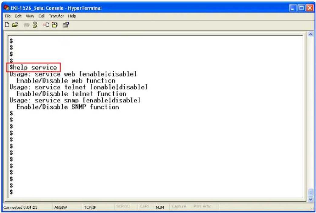
[Usage] service web enable|disable
[Function] Enable or disable the web-based configuration
[Usage] service telnet enable|disable
[Function] Enable or disable the telnet console
[Usage] service SNMP enable|disable
[Function] Enable or disable the SNMP function
Appendix A
Pin Assignments
A.1 Pin Assignments
A.1.1 RS-232 Pin Assignments
| Pin No. | Description |
| Pin 1 | DCD |
| Pin 2 | Rx |
| Pin 3 | Tx |
| Pin 4 | DTR |
| Pin 5 | GND |
| Pin 6 | DSR |
| Pin 7 | RTS |
| Pin 8 | CTS |
| Pin 9 | - |
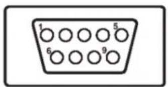
A.1.2 RJ-45 Cable PIN Assignments
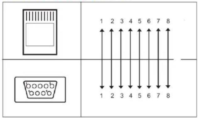
A.1.2.1 1. RS-422
| Pin No. | Description |
| 1 | Tx- |
| 2 | Tx+ |
| 5 | GND |
| 3 | Rx+ |
| 4 | Rx- |
A.1.2.2 2. RS-485
| Pin No. | Description | ||
| 1 | D | a | t |
| 2 | D | a | t |
| 5 | GND |

ADVANTECH
eAutomation
www.advantech.com
Please verify specifications before quoting. This guide is intended for reference purposes only.
All product specifications are subject to change without notice.
No part of this publication may be reproduced in any form or by any means, electronic, photocopying, recording or otherwise, without prior written permission of the publisher.
All brand and product names are trademarks or registered trademarks of their respective companies.
© Advantech Co., Ltd. 2008