
HFB4M - Camera Speco Technologies - Free user manual and instructions
Find the device manual for free HFB4M Speco Technologies in PDF.

| Product Type | 4MP FIT TVI Motorized Zoom Focus Camera |
| Image Sensor | 1/2.8" SONY STARVIS 5.69 Mega CMOS Sensor |
| Effective Pixels | 2616(H) x 1964(V), 5.14M Pixels |
| Resolution | 720P, 1080P, 1440P, 1944P |
| Lens | 2.8-12mm Motorized Lens with Auto Focus |
| Minimum Illumination | 0.01 Lux @ F1.2 |
| Video Output | HD-Analog (TVI, CVBS) |
| Signal-to-Noise Ratio | More than 50dB |
| Wide Dynamic Range (WDR) | ON/OFF (LINE/FRAME, LOW/MIDDLE/HIGH) |
| Digital Noise Reduction (DNR) | 2D, 3DNR (OFF/LOW/MIDDLE/HIGH) |
| Smart-IR | 0~20 Level Adjustable |
| Defog | OFF/ON (AUTO/MANUAL, LOW/MIDDLE/HIGH) |
| Privacy Masking | OFF/ON, 16 Zone (Box or Polygon) |
| Sens-Up | OFF/AUTO (x2 ~ x32) |
| Day & Night | Auto (AGC)/COLOR/BW/EXTERN |
| Power Supply | DC 12V (Max 8.5W / 0.71A) or AC 24V (Max 7.9W / 0.53A) |
| Operating Temperature | -10°C ~ +50°C (14°F ~ 122°F), RH 95% Max. |
| Dimensions (WxHxD) | 3.74" x 3.4" x 9" (95 x 86 x 229 mm) |
| Weight | 1.54 lbs (0.7 kg) |
| Warranty | 5 Years (Parts and Labor) |
Frequently Asked Questions - HFB4M Speco Technologies
User questions about HFB4M Speco Technologies
0 question about this device. Answer the ones you know or ask your own.
Ask a new question about this device
Download the instructions for your Camera in PDF format for free! Find your manual HFB4M - Speco Technologies and take your electronic device back in hand. On this page are published all the documents necessary for the use of your device. HFB4M by Speco Technologies.
USER MANUAL HFB4M Speco Technologies
Speco Technologies is constantly developing product improvements.
We reserve the right to modify product design and specifications without notice and without incurring any obligation.
Rev. 01/01/2020
Contents
- Contents......2
- Precautions....3, 4
Safety Instructions 5
Package Contents......6
● Camera Installation....7-10
Specifications....11,12
Camera Dimension 13
Features....14
OSD Menu Details 15-28
● Trouble Shooting....29
Precautions
Do not install the camera in extreme temperature conditions.
natural_image
Cartoon illustration of two anthropomorphic surveillance cameras emitting flames, with a cloud above (no text or symbols)Only use the camera under conditions where temperatures are between -10°C and +50°C. Be especially careful to provide ventilation when operating under high temperatures.
Do not install the camera under unstable lighting conditions.

natural_image
Illustration of two cartoon-style surveillance cameras with warning lights, no text or symbols presentSevere lighting change or flicker can cause the camera to work improperly.
Do not touch the front lens of the camera.

natural_image
Illustration of a hand holding a small device next to a circular device with angry faces (no text or symbols)This is one of the most important parts of the camera. Be careful not to leave fingerprints on the lens cover.
Never keep the camera pointed directly at strong light.

natural_image
Illustration of a sun shining on a camera and a satellite with a smiling face (no text or symbols)It can cause malfunctions to occur.
Do not drop the camera or subject it to physical shocks.

natural_image
Cartoon illustration of a flying saucer with angry face and smoke, falling off water (no text or symbols)Housing damage can compromise weatherproof ratings.
Do not expose the camera to radioactivity.

natural_image
Illustration of two cartoon-style icons: a radiation symbol and a surprised robot, both with expressive faces (no text or symbols present)If exposed to radioactivity the CCD will fail.
NOTE
* If the camera is exposed to spotlight or object reflecting strong light, smear or blooming may occur.
* please check that the power satisfies the normal specification before connecting the camera.

The lightning flash with an arrowhead symbol, within an equilateral triangle is intended to alert the user to the presence of uninsulated dangerous voltage within the product's enclosure that may be of sufficient magnitude to constitute a risk of electric shock to persons.

The exclamation point within an equilateral triangle is intended to alert the user to the presence of important operating and maintenance (servicing) instructions in the literature accompanying the appliance.
In USA and Canada, Use Class 2 Power Supply Only
INFORMATION - This equipment has been tested and found to comply with limits for a Class A digital device, pursuant to part 15 of the FCC Rules & CE Rules. These limits are designed to provide reasonable protection against harmful interference when the equipment is operated in a commercial environment. This equipment generates, uses, and can radiate radio frequency energy and, if not installed and used in accordance with the instruction manual, may cause harmful interference to radio communications. Operation of this equipment in a residential area is likely to cause harmful interference in which case the user will be required to correct the interference at their own expense.
WARNING - Changes or modifications not expressly approved by the manufacturer could void the user's authority to operate the equipment.
WARNING - To prevent electric shock and risk of fire hazards:
◆Do NOT use power sources other than that specified.
◆Do NOT expose this appliance to rain or moisture.
Apparatus shall not be exposed to dripping or splashing and no objects filled with liquids, such as vases, shall be placed on the apparatus.
CAUTION : To prevent electric shock and risk of fire hazards:
Do NOT use power sources other than those specified.
Safety Instructions
Precautions for use
- This camera should be installed by qualified personnel only
There are no user serviceable parts inside
Do not disassemble this camera other than to make initial adjustments
Use a UL approved regulated 24 volt AC or 12 volt DC power supply - Use appropriate low voltage power cable to prevent fire or electrical shock
Please insure that your installation area can support the weight of the camera
Please handle this camera carefully :
Do not use a strong or abrasive detergent when cleaning the camera
Do not install near cooling or heating device
Package Contents
Please make sure that the following items are included in the Package:
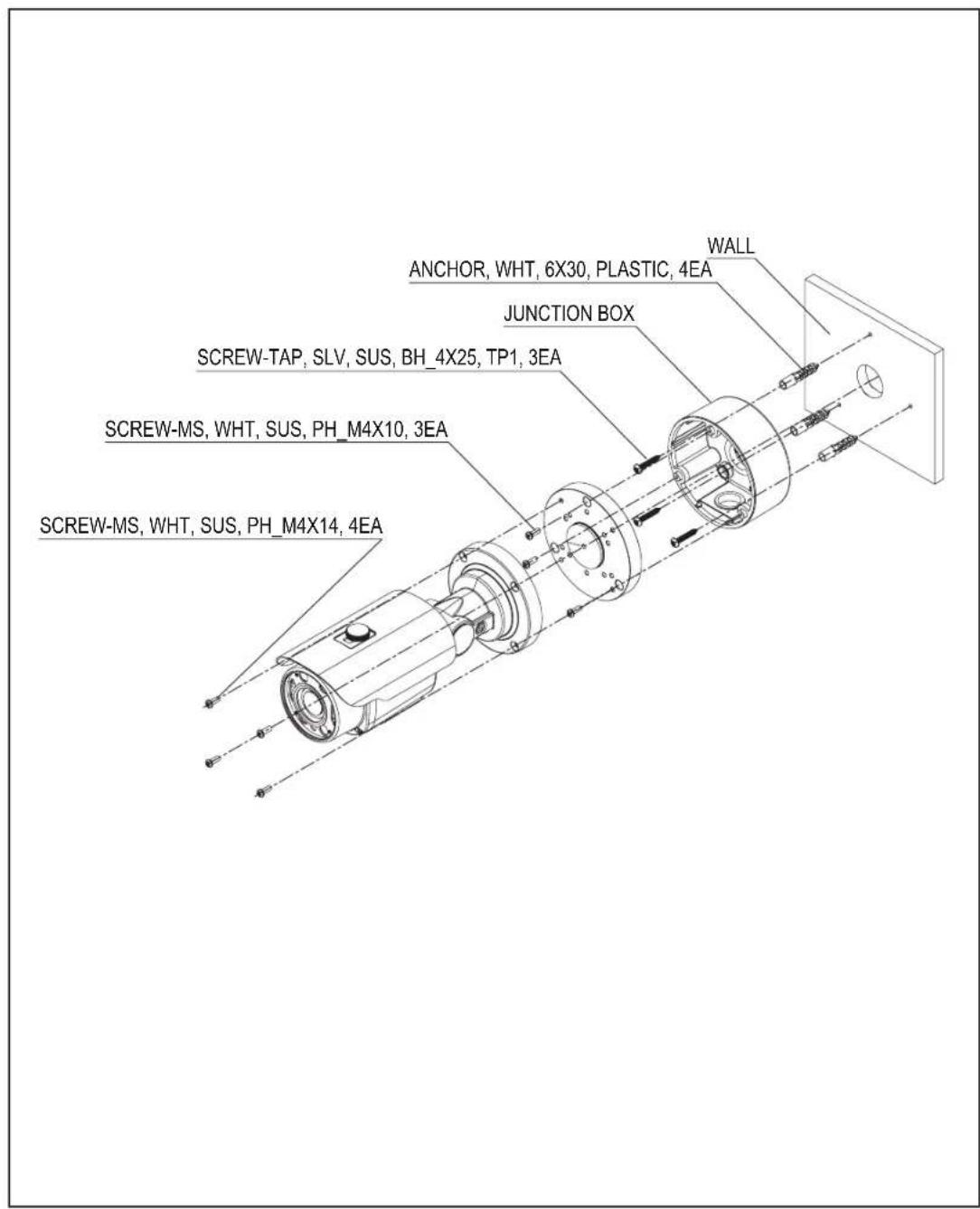
1) HFB4M Included Junction Box
• 1 Power Jack
• 1 Mount Base Sticker
• 1 Wrench
- Set Screw
- 3 Tapping Screws 4x25
- 4 Hexagon Socket Screws M4x14
- 3 Plastic Anchor
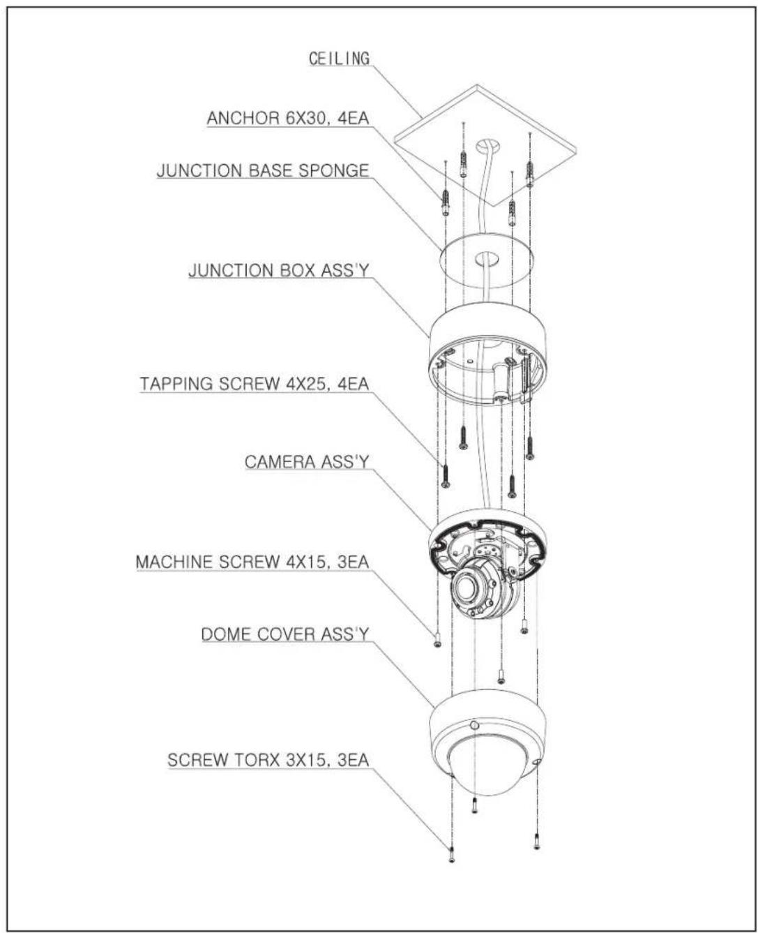
2) HFD4M Included Junction Box
• 1 Power Jack
• 1 Chameleon Cover
• 1 Junction Box Sponge
• 1 Wrench
- Set Screw
- 4 Tapping Screws 4x25
- 3 MachineScrews M4x15
- 4 Plastic Anchor
Camera Installation
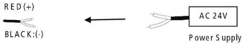
CONNECT POWER CABLE
- WHEN USING 12 VOLTS DC (constant voltage 500mA)

- WHEN USING 24 VOLTS AC (40 Volt Amps)
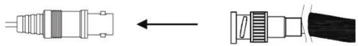
- CONNECT VIDEO CABLE
CONNECT BLACK COLOR BNC CABLE TO THE BNC JACK.
natural_image
Diagram showing two types of electrical connectors: one with a wire and connector, the other with a black cable (no text or symbols)Camera Installation
Compatibility
1) HFB4M

2) HFD4M

Camera Installation
1. HFB4M
Camera Installation
2. HFD4M
4MP FIT TVI Motorized Zoom Focus Camera
2.8-12mm MFZ Lens

natural_image
Exterior view of a black surveillance camera with mounting flange (no visible text or symbols)HFB4M (2.8-12mm)
SPECIFICATIONS
| MODEL | HFB4M | |
| Image sensor | Sensor type | 1/2.8" SONY STARVIS 5.69Mega CMOS Sensor |
| Effective pixels | 2616(H) X 1964(V), 5.14M Pixels | |
| Total pixels | 2704(H) X 2104(V), 5.69M Pixels | |
| Resolution | 720P/1080P/1440P/1944P | |
| Framelate | NTSC 30P, PAL 25P, 20P, 12.5P | |
| Scanning system | Progressive Scan | |
| Min. illumination | 0.01 Lux @ F1.2 | |
| Video Output | HD-Analog | TVI,CVBS |
| S/N Ratio | More than 50dB | |
| Lens | Drive Type | 2.8-12mm Motorized Lens with Auto Focus |
| Function | AGC | 0 ~ 10 Level Adjustable |
| Shutter Speed | AUTO /FLK/ MAMUAL(1/30Sec ~ 1/30000Sec) | |
| Brightness | 0 ~ 20 Level Adjustable | |
| Sens-UP | OFF/AUTO (x2 ~ x32) | |
| WDR | OFF/ON(LINE/FRAME)LOW/MIDDLE/HIGH | |
| BLC | OFF/ON | |
| HLC | OFF/ON | |
| ACE(D-WDR/ATR-EX) | OFF/ON(LOW/MIDDLE/HIGH) | |
| Privacy Masking | OFF/ON (16 Zone) | |
| DEFOG | OFF/ON(LOW/MIDDLE/HIGH) | |
| D-ZOOM | 1.0x ~ 16.0x | |
| Day & Night | Auto(AGC)/COLOR/BW/EXTERN(Lux CTL, PWM CTL) | |
| Smart -IR | 0~20 Level Adjustable | |
| White Balance | AUTO(1,700K ~ 11,000K)/AUTOext/PRESET/Manual | |
| DNR | 2D, 3DNR | |
| Mirror | MIRROR/FLIP | |
| Sharpness | 0~10 Level Adjustable | |
| Defog | OFF/ON | |
| Gamma Correction | 0.45 ~ 0.75 | |
| Shading | OFF/ON | |
| Language | ENG/KOR/CHN1/CHA2/JPN | |
| Power Consumption | DC 12V: Max 8.5W / 0.71A, AC 24V: Max 7.9W / 0.53A | |
| Operating Temperature | -10 ~ +50 Deg C. RH 95% Max. | |
| Storage Temperature | -20 ~ +60 Deg C. RH 95% Max. | |
| Dimensions | 3.74"(W)*3.4"(H)*9"(D) | |
| Weight | 1.54lbs | |
4MP FIT TVI Motorized Zoom Focus Camera
2.8-12mm MFZ Lens

natural_image
Close-up of a black speccal surveillance camera (no visible text or symbols on body)SPECIFICATIONS
HFD4M (2.8-12mm)
| MODEL | HFD4M | |
| Image sensor | Sensor type | 1/2.8" SONY STARVIS 5.69Mega CMOS Sensor |
| Effective pixels | 2616(H) X 1964(V), 5.14M Pixels | |
| Total pixels | 2704(H) X 2104(V), 5.69M Pixels | |
| Resolution | 720P/1080P/1440P/1944P | |
| Framelate | NTSC 30P, PAL 25P, 20P, 12.5P | |
| Scanning system | Progressive Scan | |
| Min. illumination | 0.01 Lux @ F1.2 | |
| Video Output | HD-Analog | TVI,CVBS |
| S/N Ratio | More than 50dB | |
| Lens | Drive Type | 2.8-12mm Motorized Lens with Auto Focus |
| Function | AGC | 0 ~ 10 Level Adjustable |
| Shutter Speed | AUTO /FLK/ MAMUAL(1/30Sec ~ 1/30000Sec) | |
| Brightness | 0 ~ 20 Level Adjustable | |
| Sens-UP | OFF/AUTO (x2 ~ x32) | |
| WDR | OFF/ON(LINE/FRAME)LOW/MIDDLE/HIGH | |
| BLC | OFF/ON | |
| HLC | OFF/ON | |
| ACE(D-WDR/ATR-EX) | OFF/ON(LOW/MIDDLE/HIGH) | |
| Privacy Masking | OFF/ON (16 Zone) | |
| DEFOG | OFF/ON(LOW/MIDDLE/HIGH) | |
| D-ZOOM | 1.0x ~ 16.0x | |
| Day & Night | Auto(AGC)/COLOR/BW/EXTERN(Lux CTL, PWM CTL) | |
| Smart -IR | 0~20 Level Adjustable | |
| White Balance | AUTO(1,700K ~ 11,000K)/AUTOext/PRESET/Manual | |
| DNR | 2D, 3DNR | |
| Mirror | MIRROR/FLIP | |
| Sharpness | 0~10 Level Adjustable | |
| Defog | OFF/ON | |
| Gamma Correction | 0.45 ~ 0.75 | |
| Shading | OFF/ON | |
| Language | ENG/KOR/CHN1/CHA2/JPN | |
| Power Consumption | DC 12V: Max 8.5W / 0.71A, AC 24V: Max 7.9W / 0.53A | |
| Operating Temperature | -10 ~ +50 Deg C. RH 95% Max. | |
| Storage Temperature | -20 ~ +60 Deg C. RH 95% Max. | |
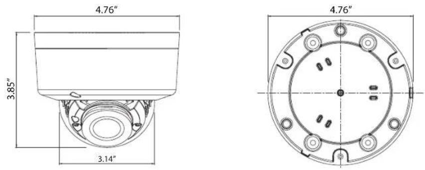
| Dimensions | 4.76"(Dia)*3.85"(H) | |
| Weight | 1.0 lbs | |
Camera Dimension
1) HFB4M

2) HFD4M
General Features
● Transfer Video Interface
The combination of a 5Mega CMOS image sensor and TVI DSP provides an excellent resolution of TVI picture.
● DNR
Smart DNR prevents the image blurring of moving object and activates only if moving objects are appearing on the scene.
Smart-IR
No saturation image, vivid image in darkness! "TVI" camera makes very sharp video image in darkness! This technology eliminates saturation of video image of the closer object in darkness by control of the IR sensitivity. Saturation never happens in our "TVI" cameras, you can enjoy vivid image in any dark condition!
- Sens-Up
Despite a limited & low light condition, Sens-Up - Max. x32 helps the viewer to get visible and clear images.
- Defog
Defog function “improves” the clarity of images taken in poor conditions such as fog, smoke, rain or snow.
● WDR
A powerful and advanced technology that captures a high resolution picture even where images appear dark.
● CVBS(Composite Video Blanking and Sync)
TV system is switchable 'NTSC' or 'PAL' with built-in OSD.
● Intelligent Function
An extraordinary technology that enables Speco Technologies TVI to become the ultimate solution by providing intelligent features based on motion detection. It also strengthens crime prevention and detection.
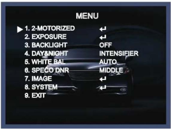
How to Set Up the camera menu
- Setup Menu
MENU
| SPECO PRESET MODE default | ||||||
| INDOOR | OUTDOOR | LOWLIGHT | HALLWAY | LOBBY | ELEVATOR | |
| LENS | DC LENS : INDOORMANUAL LENS : AUTO | DC LENS : OUTDOORMANUAL LENS : AUTO | DC LENS : INDOORMANUAL LENS : AUTO | DC LENS : INDOORMANUAL LENS : AUTO | DC LENS : INDOORMANUAL LENS : AUTO | DC LENS : INDOORMANUAL LENS : AUTO |
| SENS-UP | X8 | X16 | X32 | X8 | X8 | X8 |
| BACKLIGHT | OFF | OFF | OFF | OFF | WDR | OFF |
| DNR | HIGH | HIGH | HIGH | MIDDLE | LOW | LOW |
SPECO TECH
| 1.PRESET | INDOOR / OUTDOOR / LOW LIGHT / HALLWAY / LOBBY(WDR) / ELEVATOR | ||||
| 2.MAIN SETUP | 1.2-MOTORIZED | AF MODE | ONESHOT/MANUAL | ||
| D&N FILTER | SYNC OFF/SYNC ON | ||||
| INITIALIZE | ON(PUSHING) | ||||
| RETURN (SAVE/CANCEL) | |||||
| 2.EXPOSURE | BRIGHTNESS | 0~20 default: 10 | |||
| SHUTTER | AUTO | INDOOR/OUTDOOR/DEBLUR | |||
| RETURN (SAVE/CANCEL) | |||||
| MANUAL | 1/30, 1/60, 1/120, 1/250, 1/700, 1/1000, 1/1600, 1/2500, 1/5000, 1/7000, 1/10000, 1/30000(30P)1/60, 1/120, 1/250, 1/700, 1/1000, 1/1600, 1/2500, 1/5000, 1/7000, 1/10000, 1/30000, 1/50000(60P) | ||||
| FLICKER | |||||
| SENS-UP | OFF, X2, X4, X8, X16, X32 | ||||
| AGC | 0~10 default: 10 | ||||
| RETURN (SAVE/CANCEL) | |||||
| 3.BACKLIGHT | OFF | ||||
| HLC | LEVEL | 0~20 default: 10 | |||
| MODE | BLK/WHT/YEL/CYN/GRN/MAG/RED/BLU | ||||
| RETURN | |||||
| BLC | H-POS | 0~20 default: 11 | |||
| V-POS | 0~19 default: 10 | ||||
| H-SIZE | 0~20 default: 3 | ||||
| V-SIZE | 0~12 default: 3 | ||||
| RETURN (SAVE/CANCEL) | |||||
| WDR | WDR MODE | LINE/FRAME | |||
| OFF | |||||
| BOX | WINDOW ZONE | ||||
| WINDOW USE | |||||
| H-POS | |||||
| V-POS | |||||
| H-SIZE | |||||
| V-SIZE | |||||
| RETURN (SAVE/CANCEL) | |||||
| POLYGON | WINDOW ZONE | 0~3 default: 0 | |||
| WINDOW USE | ON/OFF | ||||
| POS0-X | default: 420 | ||||
| POS0-Y | default: 240 | ||||
| POS1-X | default: 730 | ||||
| POS1-Y | default: 240 | ||||
| POS2-X | default: 426 | ||||
| POS2-Y | default: 540 | ||||
| POS3-X | default: 726 | ||||
| POS3-Y | default: 540 | ||||
| RETURN (SAVE/CANCEL) | |||||
| WEIGHT | LOW/MIDDLE/HIGH | ||||
| RETURN (SAVE/CANCEL) | |||||
How to Set Up the camera menu
- Setup Menu
MENU
| 4.DAY&NIGHT | AUTO | D>N THRES(AGC) | 0~20 default: 13 | |||
| N>D THRES(AGC) | 0~20 default: 3 | |||||
| DELAY | LOW, MIDDLE, HIGH | |||||
| RETURN (SAVE/CANCEL) | ||||||
| COLOR | ||||||
| B&W | ||||||
| EXTERN | SMART - IR | 0~20 default: 2 | ||||
| GHOST CAT | ON/OFF | |||||
| LED LEVEL | 0~10 default: 10 | |||||
| D>N THRES(CDS) | 0~20 default: 13 | |||||
| N>D THRES(CDS) | 0~20 default: 7 | |||||
| DELAY | LOW, MIDDLE, HIGH | |||||
| RETURN (SAVE/CANCEL) | ||||||
| 5.WHITE BAL | AUTO/AWB/AWC-SET | |||||
| MANUAL | C-TEMP | 3000K/5000K/8000K | ||||
| R-GAIN | 0~20 default: 10 | |||||
| B-GAIN | 0~20 default: 10 | |||||
| RETURN (SAVE/CANCEL) | ||||||
| 6.SPECO DNR | OFF/LOW/MIDDLE/HIGH | |||||
| 7.IMAGE | SHARPNESS | 0 ~ 10 default: 10 | ||||
| COLOR GAIN | 0 ~ 20 default: 10 | |||||
| GAMMA | 0.45, 0.55, 0.6, 0.65 | |||||
| MIRROR | ON/OFF | |||||
| FLIP | ON/OFF | |||||
| D-ZOOM | 1.0X ~ 16X default: 1.0X | |||||
| ACE | OFF, LOW, MIDDLE, HIGH | |||||
| DEFOG | ON | MODE | AUTO/MANUAL | |||
| LEVEL | LOW,MIDDLE,HIGH | |||||
| RETURN (SAVE/CANCEL) | ||||||
| OFF | ||||||
| SHADING | ON | WEIGHT | 0% ~ 100% default: 100% | |||
| RETURN (SAVE/CANCEL) | ||||||
| OFF | ||||||
| PRIVACY | BOX | ON | ZONE NUM | 0~15 default: 0 | ||
| ZONE DISP | ON/OFF | |||||
| H-POS | 0~60 default: 12 | |||||
| V-POS | 0~34 default: 2 | |||||
| H-SIZE | 0~60 default: 3 | |||||
| V-SIZE | 0~34 default: 3 | |||||
| Y LEVEL | 0~20 default: 10 | |||||
| CB LEVEL | 0~20 default: 10 | |||||
| CR LEVEL | 0~20 default: 10 | |||||
| TRANS | 0~3 default: 0 | |||||
| RETURN (SAVE/CANCEL) | ||||||
| OFF | ||||||
| POLYGON | ON | ZONE NUM | 0~15 default: 0 | |||
| ZONE DISP | ON/OFF | |||||
| POS0-X | default: 80 | |||||
| POS0-Y | default: 5 | |||||
| POS1-X | default: 88 | |||||
| POS1-Y | default: 5 | |||||
| POS2-X | default: 88 | |||||
| POS2-Y | default: 13 | |||||
| POS3-X | default: 80 | |||||
How to Set Up the camera menu
- Setup Menu
MENU
| POS3-Y | default:13 | |||||
| Y LEVEL | 0~20 default:10 | |||||
| CB LEVEL | 0~20 default:10 | |||||
| CR LEVEL | 0~20 default:10 | |||||
| TRANS | 0~3 default:2 | |||||
| RETURN (SAVE/CANCEL) | ||||||
| OFF | ||||||
| RETURN (SAVE/CANCEL) | ||||||
| 8.SYSTEM | VIDEO OUTPUT | OUTPUT | TVI | |||
| FRAME RATE | 720/30P, 1080/30P, 1440/30P, 1944/20P, 1944/12.5P | |||||
| FREQ | 50HZ/60HZ | |||||
| CONFIRM | YES(PUSH) | |||||
| RETURN (SAVE/CANCEL) | ||||||
| IMAGE RANGE | FULL | |||||
| COMP | ||||||
| USER | OFFSET | 0~32 default:10 | ||||
| RETURN | ||||||
| LANGUAGE | ENG, CHN, CHN(S), JPN, KOR | |||||
| CAM TITLE | OFF | |||||
| RIGHT UP | ||||||
| LEFT DOWN | ||||||
| RESET | ON-PUSHING | |||||
| RETURN (SAVE/CANCEL) | ||||||
| 9.EXIT | SAVE/CANCEL | |||||
| 3.EXIT | ||||||
Menu Set Up
Menu items can be selected by using the OSD buttons of the camera.
- PRESET

1-1. Preset : INDOOR / OUTDOOR / LOW LIGHT / HALLWAY / LOBBY(WDR) / ELEVATOR.
- Used for a quick and easy setup for the installation environment.
* The Advanced Set Up menu will be displayed on the monitor.
- Move and select the required function using the Up and Down button.
* Move the triangular indicator Up or Down to select the desired feature by pressing the Up or Down button.

- Change menu settings using the Left or Right button.
* Available values or Status are displayed by pressing the Left or Right buttons. Press the button until desired value / status is displayed.
- After Changing the setting move the arrow indicator to EXIT and press the SET button to EXIT.
NOTE
* Move to the available submenu by moving ←arrow to desired feature.
* Submenu is not available when this symbol displayed “---”.
1. 2-MOTORIZED
- Move the triangular indicator to 2-MOTORIZED using the Up and Down buttons on the Set Up menu screen.
- Select the desired lens type by pressing the Left of Right button.
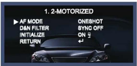
◆ AF MODE
- ONESHOT : Adjust zoom and focus automatically.
- MANUAL : Adjust zoom and focus manually.
◆ D&N FILTER[ON/OFF] : Adjust zoom and focus when Day & Night is changing.
◆ INITIALIZE : If you press OSD button 3\~4 seconds, Lens Initializing start.
2. EXPOSURE
- On the Set Up menu, Select EXPOSURE by using the Up or Down button.

- Select the desired shutter mode by pressing the Left or Right button.
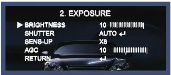
◆ BRIGHTNESS : The brightness can be adjusted. The brightness control range is 1\~20.
◆ SHUTTER : DC lens is launched with the setting of 1/30 and the manual lens is launched with the setting of Auto shutter, but the shutter speed can be adjusted from 1/30 to 1/50,000.
→ FLK : Select FLK mode if flickering occurs ; caused by the unmatched frequency of electric light.
◆ SENS-UP : The bright screen can be displayed by sensing the degree of the darkness automatically under the circumstance of low light condition or at night.
→ Off \~x32 Level Adjustable.
◆ AGC (Auto Gain Control) : The higher the AGC level is, the more noises appear.
→ 0\~10 Level selectable.
NOTE
* Sens-Up mode is not worked when Electronic shutter is selected as Manual.
3. BACKLIGHT
On this menu, backlight image can be compensated by users selecting one of modes. (HLC, BLC, WDR)
- Move the triangular indicator to BACKLIGHT on the SETUP menu screen using the Up and Down button.
- Select the desired mode by using the left or Right button.
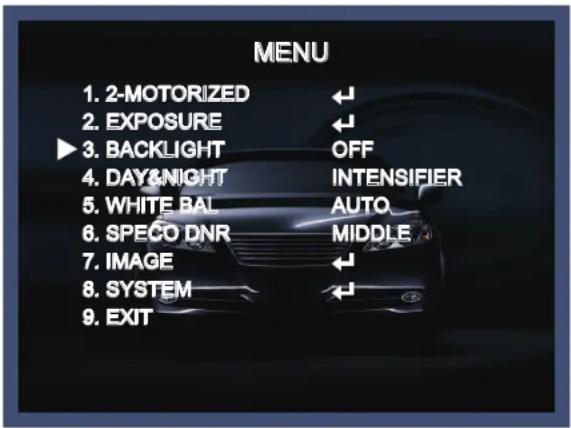
◆ Off : Deactivated status.
◆ HLC : This function is used to surpress or strong light source (for example, headlights of cars during nighttime) so that other subjects can be seen in more detail. If you select HLC, a submenu appears where you can make finer adjustments.
- LEVEL : Adjust the brightness level from which on the light source is to be masked out.
0\~20 level adjustable.
- MODE : Select the color of HLC range.

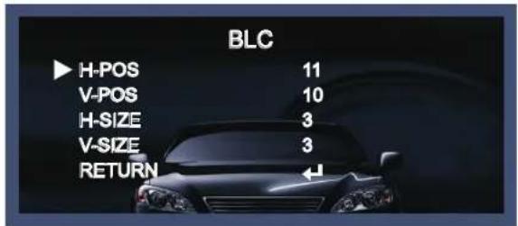
◆ BLC : This function is used to counterbalance the screen image by increasing the brightness so that a subject which appears dark due to a strong backlight can be displayed in more detail. If you select BLC, a submenu appears where you can make finer adjustments.
- H-POS/V-POS/H-SIZE/V-SIZE : Define the position and size of the area of interest by changing the position & size.
◆ WDR : The WDR (Wide Dynamic Range) function works to correct excessive light within the frame to produce a usable image. When the image has simultaneous bright and dark areas, it makes both areas distinct. If you select WDR, a submenu appears where you can make finer adjustments.

- WDR MODE : The Specific WDR area can be selected.
* BOX
WINDOW ZONE [0\~3]
WINDOW USE [ON/OFF]
H-POS [1\~1920] : You can select the horizontal starting position of the monitoring area.
V-POS [1\~1080] : You can select the vertical starting position of the monitoring area.
H-ZISE [1\~1920]: You can select the horizontal size of the monitoring area.
V-SIZE [1\~1080]: You can select the vertical size of the monitoring area.
* POLYGON
WINDOW ZONE [0\~3]
WINDOW USE [ON/OFF]
POS0-X : You can select the horizontal & Diagonal starting position of the monitoring area.
POS0-Y : You can select the vertical & Diagonal starting position of the monitoring area.
POS1-X : You can select the horizontal & Diagonal starting position of the monitoring area.
POS1-Y : You can select the vertical & Diagonal starting position of the monitoring area.
POS2-X : You can select the horizontal & Diagonal starting position of the monitoring area.
POS2-Y : You can select the vertical & Diagonal starting position of the monitoring area.
POS3-X : You can select the horizontal & Diagonal starting position of the monitoring area.
POS3-Y : You can select the vertical & Diagonal starting position of the monitoring area.
- WEIGHT [MIDDLE, HIGH, LOW] : Select the WDR level of the camera.
4. DAY&NIGHT
You can change the color mode of color or black / white by setting up the mode.
- Select Day&Night using the Up or Down button on the Set Up menu screen.
- Select the desired mode using the Left or Right buttons.

INTENSIFIER : The bright screen can be displayed by sensing the degree of the darkness automatically under the circumstance of low light condition or at night.
◆ AUTO : Automatically, It shifts into the color mode in the bright environment and the B/W mode in the low light condition. It can adjust the delay time, starting brightness and end brightness according to the ambient conditions by pressing the Set button.
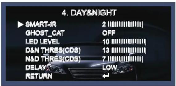
- SMART IR.: 0\~20 smart IR level adjustable.
- GHOST_CAT[ON/OFF] : Get rid of Ghost phenomenon (image dragging) when set-up the SENS-UP.
- LED LEVEL : 0\~10 IR ADJUST level adjustable.
- D>N THRES(CDS) : 0\~20 CDS THRES level adjustable.
- N>D THRES(CDS): 0\~20 CDS THRES level adjustable.
- DELAY [LOW/MIDDLE/HIGH] : Set the delay time for switching between COLOR and B/W.
5. WHITE BAL
Use this function when the color adjustment of a screen is needed.
- Move the triangular indicator to WHITE BAL on the SETUP menu screen using the Up and Down button.
- Select the desired mode by using the left or Right button.
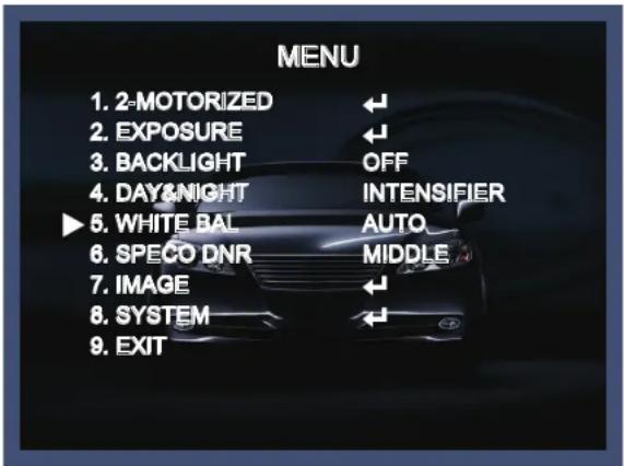
◆ AUTO : Use this mode when the color temperature is from 3,000k to 8,000k.
◆ AWB : The function to search for the color which is matched well with the ambient environment.
◆ AWC→SET : After letting camera focus on the blank white paper to the best condition of current lighting environment, press the SET button. If the lighting condition is changed, Re-adjustment should be needed.
◆ MANUAL : Manual compensation make the more detailed control possible. First, after adjusting the white balance using the ATW or AWB mode, change the mode into the manual compensation mode and then press Set button. While looking at the color change of the subject seen on the screen after setting up the proper color temperature, increase the each value of the blue and the red.
- C-TEMP : 3000K/5000K/8000K level adjustable.
- R-GAIN : 0\~20 level adjustable.
- B-GAIN : 0\~20 level adjustable.
- Return : Every function is set up at the WHITE BAL menu, and then return the previous menu.
NOTE
The White Balance may not be worked properly in the following conditions. If this doesn't work, use the AWB mode.
* When there is a very high color temperature in the circumstances of the subject. (for example, clear sky, Sunset)
* It is very dark.
* If the camera is headed to the fluorescent light directly or if there is a drastic lighting change, The operation of White balance may become unstable.
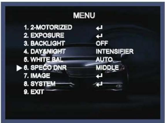
6. SPECO DNR
This function is used to improve the picture quality by filtering the noise which is generated under low brightness conditions. You can set different levels here.
- Move the triangular indicator to SPECO DNR by using the Up and Down button.
- Select the mode to use by pressing the left or Right button and OFF/LOW/MIDDLE/HIGH level selectable.
7. IMAGE
When selecting, the following submenu will appear.
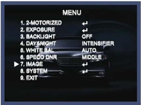
Here you can optimise the image quality by adjusting different options.
![7. IMAGE SHARPNESS 10 [########] COLOR GAIN 10 [########] GAMMA 0.65 MIRROR OFF FLIP OFF D-ZOOM 1.0X ACE OFF DEFOG OFF SHADING OFF PRIVACY ← RETURN ←](/content/2026/06/1194429/images/1f0f0ef1a469f64e907ce1baaa7db2f6ad582bd467048944b6f1ac926c45a24f.jpg)
◆ SHARPNESS [1 \~ 10] : Adjusts the image sharpness. If the level goes up excessively, it may affect the video image and generate a noise.
◆ COLOR GAIN [0 \~ 20] : Changes the color gain of the camera.
◆ GAMMA [0.45 \~ 0.65] : Changes the gamma curve of the camera.
◆ MIRROR [ON, OFF] : Mirrors the image horizontally on the screen.
◆ FLIP [ON, OFF] : Flips the image vertically on the screen.
◆ D-ZOOM: You can use the digital zoom with x1\~x16 magnifications.
◆ ACE [OFF/LOW/MIDDLE/HIGH] : Intelligent lighting level control to over come even strong backlight conditions.
◆ DEFOG [ON, OFF] : This function helps to recognize the object in a dusty weather condition. ON, a submenu appears where you can make finer adjustments.
◆ SHADING [ON, OFF] : Compensates the shading effects of lenses when the lens is set to a very wide angle. This function will reduce the brightness difference between the centre and the edges. If you select ON, a submenu appears where you can make finer adjustments.
◆ PRIVACY [ON, OFF] : This is used to hide certain areas on the monitor. You can designate each different 15 area. The size of a designated area can be adjusted. The color of a privacy area can be selected various colors. When you select the return, the setting values in this function menu are saved, then get out of this menu.
\* BOX
ZONE NUM [0\~15] : Select a mask out of the 16 mask areas and set the options below for the selected mask.
ZONE DISP [ON, OFF] : Choose ON to activate privacy masks and press OFF to deactivate masks.
H-POS [0\~60] : Define the horizontal start position of the privacy mask.
V-POS [0\~34]: Define the vertical start position of the privacy mask.
H-SIZE [0\~60] : Define the horizontal size of the privacy mask.
V-SIZE [0\~34] : Define the vertical size of the privacy mask.
Y LEVEL [0\~20] : Define the brightness of the mask color.
CB LEVEL [0\~20] : Define the blue amount of the mask color.
CR LEVEL [0\~20] : Define the red amount of the mask color.
TRANS [0\~3] : Applies a tone from the window to act on the selected area.
\* POLYGON
ZONE NUM [0\~15] : Select a mask out of the 16 mask areas and set the options below for the selected mask.
ZONE DISP [ON, OFF] : Choose ON to activate privacy masks and press OFF to deactivate masks.
POS0-X : You can select the horizontal & Diagonal starting position of the monitoring area.
POS0-Y : You can select the vertical & Diagonal starting position of the monitoring area.
POS1-X : You can select the horizontal & Diagonal starting position of the monitoring area.
POS1-Y : You can select the vertical & Diagonal starting position of the monitoring area.
POS2-X : You can select the horizontal & Diagonal starting position of the monitoring area.
POS2-Y : You can select the vertical & Diagonal starting position of the monitoring area.
POS3-X : You can select the horizontal & Diagonal starting position of the monitoring area.
POS3-Y : You can select the vertical & Diagonal starting position of the monitoring area.
Y LEVEL [0\~20] : Define the brightness of the mask color.
CB LEVEL [0\~20] : Define the blue amount of the mask color.
CR LEVEL [0\~20] : Define the red amount of the mask color.
TRANS [0\~3] : Applies a tone from the window to act on the selected area.
8. SYSTEM
This can be used when you want to select the additional function control.
-
When the SETUP menu is displayed, select SYSTEM using the Up and Down button.
-
Select one of the mode using the Up and Down button.

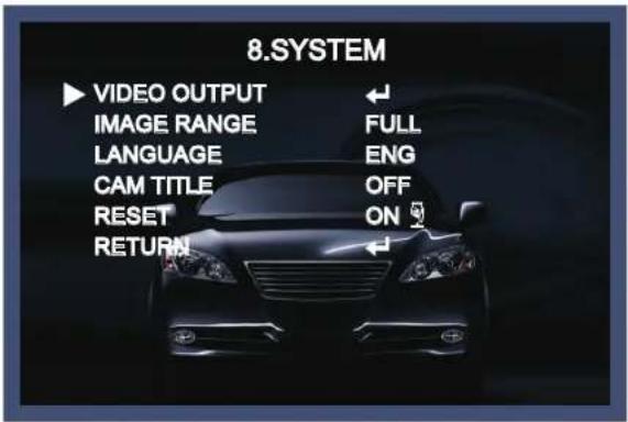
VIDEO OUTPUT
- OUTPUT : TVI.
- FRAME RATE[720/30P, 1080/30P, 1440/30P, 1944/20P, 1944/12.5P] : Choose output type.
- FREQ[60Hz/50Hz] : You can select PAL (25FPS) or NTSC (30FPS).
- CONFIRM : Apply the setting value of output mode. (If confirm is not applied after changing the output mode, the setting value is not changed.)
◆ IMAGE RANGE : Adjust the rate of YC signal to 100%(FULL), 75%(COMP) or 100%\~75%(USER).
◆ LANGUAGE : ENG, CHN, CHN(S), JPN, KOR
◆ CAM TITLE : It can be adjusted when you get into the Cam Title menu. This function is to display the letters of the camera on the monitor.
◆ RESET [ON] : All settings will be restored to factory default.
Exit
Press the Set button in the exit menu to save the current settings and exit the Set Up menu.
Trouble Shooting
| PROBLEM | POSSIBLE CAUSE |
| Nothing appears on the screen. | Check the power cable, power supply output and video connection between the camera and monitor. |
| The image on the screen is dim. | Are the camera lens or the lens glass dirty?Clean the lens / glass with a soft clean cloth.Adjust the monitor controls, as required.If the camera is facing a very strong light, change the camera position.Adjust the lens focus. |
| The image on the screen is dark. | Adjust the contrast control of the monitor.If there is an intermediate device, correctly set the 75Ω/Hz. |
| The camera is not working properly and the surface of the camera is hot. | Check the camera is correctly connected to an appropriate regulated power source. |
| Motion Detection is not activated. | Has MOTION DET been set to ON in the menu?Has MD AREA been properly defined? |
| The color of the picture is not correct. | Check the settings in WHITE BALANCE menu. |
| The image on the screen flickers. | Make sure that the camera isn't facing direct sunlight or fluorescent lighting. If necessary,change the camera position. |
| The SENS-UP does not work. | Check that the AGC setting in the EXPOSURE menu is't set to OFF. |
| Auto-Focusing Is Not Working Properly. | 1. VERY RARELY, the auto-focusing may not work.But, this is not a defect. This symptom occurs due to the product's specific feature.For this reason, if you experience this symptom, then please manually move the control board once to the left and once to the right.Then, the focusing will be corrected and working properly as it should.2. (Recommendation) ONE PUSH FeatureIn case the focusing does not work, please do the following to correct this problem.Menu -> 1. 2MOTOR -> 3. ONEPUSHAF -> Push the "ON" button for 1 second. -> The Auto Focusing will begin upon changing to "PUSHING". |
speco technologies®
LIMITED WARRANTY - VIDEO PRODUCTS
THIS WARRANTY IS VALID ONLY ON PRODUCTS PURCHASED AND USED IN THE UNITED STATES OF AMERICA AND CANADA. THIS WARRANTY APPLIES ONLY TO THE ORIGINAL USER.
SUBJECT TO CONDITIONS AND EXCLUSIONS FOUND BELOW, THIS PRODUCT IS WARRANTED AGAINST MANUFACTURING DEFECTS IN MATERIAL AND WORKMANSHIP FOR THE FOLLOWING PERIOD FOR PARTS AND LABOR:
SPECO TECHNOLOGIES CAMERAS .... 5 YEARS
SPECO TECHNOLOGIES IP CAMERAS..... 5 YEARS
SPECO PTZ AND VL CAMERAS....1 YEAR
SPECO TECHNOLOGIES MONITORS......1 YEAR
IR LEDS 90 DAYS
DVRs 5 YEARS
NVRs 5 YEARS
BALANCE OF
SPECO TECHNOLOGIES LINE .... 1 YEAR
SPECO TECHNOLOGIES WILL REPAIR OR REPLACE (AT OUR DISCRETION) ANY PARTS FOUND TO BE DEFECTIVE FOR THE WARRANTY PERIOD SPECIFIED. WE WILL PROVIDE A REPLACEMENT FOR ANY DEFECTIVE PART.
CONDITIONS
- YOU MUST OBTAIN A RETURN AUTHORIZATION (RA) NUMBER FOR ANY MERCHANDISE BEING RETURNED TO SPECO TECHNOLOGIES, WHETHER FOR RETURN/EXCHANGE OR REPAIR, WHETHER IN OR OUT OF WARRANTY.
- THIS WARRANTY WILL BE HONORED ONLY UPON PRESENTATION OF THE ORIGINAL DATED BILL OF SALE OR SALES SLIP.
- TRANSPORTATION OF THE PRODUCT TO OUR SERVICE DEPARTMENT IS THE RESPONSIBILITY OF THE USER. REPAIRED OR REPLACED PRODUCT WILL BE RETURNED PREPAID DURING THE WARRANTY PERIOD.
- SPECO TECHNOLOGIES DOES NOT AUTHORIZE ANY INTERNET OR MAIL ORDER PRODUCT SALES. IF A SPECO TECHNOLOGIES PRODUCT IS PURCHASED FROM AN UNAUTHORIZED DISTRIBUTOR OR OTHER SOURCE, INCLUDING RETAILERS, MAIL ORDER SELLERS AND ONLINE SELLERS, IT WILL NOT BE HONORED OR SERVICED UNDER THE EXISTING SPECO TECHNOLOGIES WARRANTY POLICY. ANY SPECO TECHNOLOGIES PRODUCT PURCHASED FROM THESE ONLINE MERCHANTS WILL VOID THE APPLICABLE WARRANTY AND IS INELIGIBLE FOR TECHNICAL SUPPORT. IF YOU HAVE QUESTIONS ABOUT A RESELLER, PLEASE CONTACT SPECO TECHNOLOGIES AT 1-800-645-5516 FOR A LIST OF UNAUTHORIZED DEALERS, VISIT: www.specotech.com/unauthorized.
EXCLUSIONS
- THIS WARRANTY SHALL NOT COVER ADJUSTMENT OF CUSTOMER OPERATED CONTROLS AS EXPLAINED IN THE APPROPRIATE Model's INSTRUCTION MANUAL OR PRODUCTS WHICH HAVE BEEN ALTERED, ABUSED, OR HAVE MISSING OR ALTERED SERIAL NUMBERS.
- THIS WARRANTY SHALL NOT APPLY TO UNCRATING, SETUP, INSTALLATION, OR THE REMOVAL AND REINSTALLATION OF PRODUCTS AFTER REPAIR.
- THIS WARRANTY SHALL NOT APPLY TO REPAIRS OR REPLACEMENTS NECESSITATED BY ANY CAUSE BEYOND THE RESULT OF MANUFACTURE INCLUDING, BUT NOT LIMITED TO, ANY MALFUNCTION, DEFECTS OR FAILURE CAUSED BY OR RESULTING FROM UNAUTHORIZED SERVICE OR PARTS, IMPROPER MAINTENANCE, MODIFICATION OR REPAIR BY THE USER, ABUSE, MISUSE, NEGLECT, ACCIDENT, FIRE, FLOOD, OR OTHER ACTS OF NATURE, INCORRECT LINE VOLTAGE, DAMAGE OR IMAGE BURNS TO TELEVISION PICTURE TUBES CAUSED BY OR ATTRIBUTABLE TO THE USE OF ANY ACCESSORY, ELECTRONICS GAME OR DEVICE, OR DAMAGE CAUSED TO IMAGE PICKUP DEVICES BY EXCESSIVE LIGHT.
THE FOREGOING IS IN LIEU OF ALL OTHER EXPRESSED WARRANTIES AND WE DO NOT AUTHORIZE ANY PARTY TO ASSUME FOR US ANY OTHER OBLIGATION OR LIABILITY. IN NO EVENT SHALL WE BE LIABLE FOR INCIDENTAL OR CONSEQUENTIAL DAMAGES ARISING FROM THE USE OF THIS PRODUCT, OR FOR ANY DELAY IN THE USE OF THIS PRODUCT DUE TO CAUSES BEYOND OUR CONTROL. SOME STATES DO NOT ALLOW LIMITATIONS OF HOW LONG AN IMPLIED WARRANTY LASTS AND/OR DO NOT ALLOW THE EXCLUSION OR LIMITATION OF CONSEQUENTIAL DAMAGES. THE ABOVE LIMITATIONS ON IMPLIED WARRANTY AND CONSEQUENTIAL DAMAGES MAY NOT APPLY TO YOU.
THIS WARRANTY GIVES YOU SPECIFIC LEGAL RIGHTS. YOU MAY HAVE OTHER RIGHTS WHICH VARY FROM STATE TO STATE.
NOTE: FOR YOUR PROTECTION IN THE EVENT OF THEFT OR LOSS OF THIS PRODUCT, PLEASE FILL IN THE INFORMATION REQUESTED BELOW AND RETAIN WITH YOUR SALES RECEIPT.
MODEL NO.:
SERIAL NO.:
(LOCATED ON BACK OR BOTTOM OF UNIT)
DATE OF PURCHASE:
WHERE PURCHASED:
PURCHASE PRICE:
| Speco Technologies200 New HighwayAmityville, NY 11701www.specotech.com | FOR MORE INFORMATION REGARDING SERVICE OR RETURN,CALL US TOLL FREE: 1-800-645-5516 IN METRO NY: 631-957-8700 |
ALWAYS USE DISCRETION WHEN INSTALLING VIDEO AND/OR AUDIO SURVEILLANCE EQUIPMENT ESPECIALLY WHEN THERE IS AN EXPECTATION OF PRIVACY. INQUIRE REGARDING FEDERAL, STATE AND/OR LOCAL REGULATIONS APPLICABLE TO THE LAWFUL INSTALLATION OF VIDEO AND/OR AUDIO RECORDING OR SURVEILLANCE EQUIPMENT. PARTY CONSENT MAY BE REQUIRED.
speco technologies®
200 New Highway Amityville, NY 11701 631-957-8700 1 800 645 5516 www.specotech.com


- Contents
- Precautions
- NOTE
- In USA and Canada, Use Class 2 Power Supply Only
- Safety Instructions
- Precautions for use
- Please handle this camera carefully :
- Package Contents
- Camera Installation
- CONNECT POWER CABLE
- Compatibility
- HFB4M
- HFD4M
- 4MP FIT TVI Motorized Zoom Focus Camera
- 2.8-12mm MFZ Lens
- Camera Dimension
- General Features
- ● Transfer Video Interface
- ● DNR
- Smart-IR
- - Sens-Up
- - Defog
- ● WDR
- ● CVBS(Composite Video Blanking and Sync)
- ● Intelligent Function
- How to Set Up the camera menu
- - Setup Menu
- Menu Set Up
- 2-MOTORIZED
- EXPOSURE
- BACKLIGHT
- DAY&NIGHT
- WHITE BAL
- SPECO DNR
- IMAGE
- \* BOX
- \* POLYGON
- SYSTEM
- Exit
- speco technologies®
- LIMITED WARRANTY - VIDEO PRODUCTS
- CONDITIONS
- EXCLUSIONS
Brand : Speco Technologies
Model : HFB4M
Category : Camera