Signature Series HP15WO-3-4L - Jokofu Perlick - Free user manual and instructions
Find the device manual for free Signature Series HP15WO-3-4L Perlick in PDF.

| Product Type | Undercounter Wine Cooler |
| Brand | Perlick |
| Model | Signature Series HP15WO-3-4L |
| Category | Wine Cooler / Beverage Center |
| Dimensions (W x H x D) | 15 in x 34.5 in x 24 in (38.1 cm x 87.6 cm x 61 cm) |
| Weight | 85 lb (38.6 kg) |
| Power Supply | 115 V, 60 Hz |
| Annual Energy Consumption | ~200 kWh |
| Temperature Range | 40°F - 65°F (4°C - 18°C) |
| Capacity | Up to 40 standard wine bottles |
| Control Type | Digital touchscreen thermostat |
| Interior Lighting | LED, adjustable |
| Shelving | Wooden slide-out shelves |
| Door Type | Stainless steel framed, reversible |
| Installation | Freestanding or built-in undercounter |
| Refrigerant | R600a |
| Noise Level | < 45 dB |
| Maintenance | Clean condenser coils annually; defrost manually |
| Safety Features | Child lock, automatic defrost, temperature alarm |
| Warranty | 2 years parts and labor |
| Repairability | Replacement parts available via authorized service centers |
Frequently Asked Questions - Signature Series HP15WO-3-4L Perlick
User questions about Signature Series HP15WO-3-4L Perlick
0 question about this device. Answer the ones you know or ask your own.
Ask a new question about this device
Download the instructions for your Jokofu in PDF format for free! Find your manual Signature Series HP15WO-3-4L - Perlick and take your electronic device back in hand. On this page are published all the documents necessary for the use of your device. Signature Series HP15WO-3-4L by Perlick.
USER MANUAL Signature Series HP15WO-3-4L Perlick
PERLICK RESIDENTIAL INSTALLATION MANUAL
TABLE OF CONTENTS
Warranty Information ....2
Safety Information 4
Plumbing, Electrical and General Information ....4
Installation Instructions....5
Toe Kick Installation....7
Shelving/Drawer Adjustments....8
Door Information......8
Changing the Door Swing Direction ....8
Handle Installation....11
Door Lock Installation....11
Wood Overlay Installation....12
Wine Rack Trim....12
CONGRATULATIONS
Congratulations on your purchase of a Perlick high quality residential refrigeration product. Perlick's innovative product offering gives you the opportunity to enjoy the functionality and user friendliness in just about any room of your home, including kitchens, bedrooms, entertainment rooms, basements and even bathrooms.
All Perlick products are built with commercial grade stainless steel, providing you with the beauty and durability for a lifetime of use. This installation guide will show you how to properly install your new perlick product.
We dedicate considerable time to ensure that our products provide the highest level of customer satisfaction. If, however, service is required, call Perlick at 800.558.5592. For your own protection, never return merchandise for credit without our approval.
We thank you again for selecting a high quality Perlick product. We hope you enjoy using it.
Model Number: ____
Serial Number: ____
Purchase Date: ____
Dealer Name/Address:
Phone Number: ____
PERLICK RESIDENTIAL PRODUCTS WARRANTY
WARRANTY:
Perlick Corporation ("Perlick") warrants to the original retail purchaser that during the Basic Warranty Period, Perlick's products will be free from free from defects in material and workmanship, and during the Extended Warranty Period, the hermetically sealed refrigeration system contained in Perlick's undercounter refrigerator will be free from defects in material and workmanship. This system consists entirely of the compressor, condenser, drier, connecting tubing, evaporator and hot gas bypass valve.
The Basic Warranty Period is as follows:
- For a new product or floor display model, other than the H50IM Clear Ice Maker: The three (3) year period commencing on the date of purchase by the original retail purchaser, except that the Basic Warranty Period will be the two (2) year period commencing on the date of purchase by the original retail purchaser if the purchase of the product is not registered with Perlick within ninety (90) days of purchase in the manner described below.
- For the H50IM Clear Ice Maker or a factory second (B-Stock) product: The one (1) year period commencing on the date of purchase by the original retail purchaser.
The Extended Warranty Period applies only to the hermetically sealed refrigeration system contained in Perlick's undercounter refrigerators. The Extended Warranty Period is the portion of the six (6) year period commencing on the date of purchase by the original retail purchaser that is not covered by the Basic Warranty Period.


IMPORTANT!
Read and understand all information in this manual before attempting the installation. All plumbing and electrical work must be performed by a qualified technician and conform to all applicable state and local codes.
REMEDY:
Perlick will provide the parts and labor necessary to repair or replace (at Perlick's option) any parts proven to be defective in material or workmanship during the Basic Warranty Period. Perlick will provide the replacement parts, but not the labor, for any parts of the hermetically sealed refrigeration system proven to be defective in materials or workmanship during the Extended Warranty Period. The cost of freight to ship the replacement parts will be paid by Perlick. Replacement parts are warranted for the remainder of the original warranty period, or ninety (90) days, whichever is longer.
REGISTRATION:
Your Perlick product can be registered via the online Warranty Registration form at http://www.perlick.com/residential-products/service-support/warranty-registration/.
OTHER TERMS AND CONDITIONS:
This Warranty applies only to products installed in the fifty states of the United States, the District of Columbia and the ten provinces of Canada.
To obtain the warranty coverage described in this Warranty, Perlick or its authorized distributor or dealer must receive written notice of the warranty claim within the applicable warranty period. To receive parts and/or service and the name and telephone number of the nearest Perlick authorized service representative, please contact your Perlick dealer or distributor, or Perlick's Customer Service Department by writing to it at Perlick Corporation, Attn: Customer Service Department, 8300 West Good Hope Road, Milwaukee, Wisconsin 53223; or by calling Perlick's Customer Service Department at 800-558-5592; or by e-mailing Perlick's Customer Service Department at warrantyserv@perlick.com. In addition, you can notify Perlick of a warranty claim by visiting Perlick's website at http://www.perlick.com/residential-products/service-support/ and filling out and submitting the Technical Service Request form that appears there.
All service provided by Perlick under this Warranty must be performed by Perlick's authorized service representatives, unless otherwise specified by Perlick in writing. Service will be provided during normal business hours.
This Warranty applies only to the original retail purchaser of the Perlick product, and may not be assigned or transferred.
This Warranty does not apply to:
- Damage to Products occurring during transportation.
- Products that are used in a manner that is not normal residential or light commercial use.
- Products that are: improperly installed; misused or abused; operated with low voltage; wired in a manner not conforming to electrical codes; not properly operated in accordance with Perlick's instructions; not cleaned or maintained in accordance with Perlick's instructions; modified; or damaged by lightning or other acts of nature.
- Consumable items such as light bulbs.
- Cosmetic damage.
- Adjustments to controls, door reversal, cleaning the condenser or other routine maintenance.
- Products for which the original proof of purchase, delivery date or serial number cannot be verified.
- Products for which the defective parts are not returned for inspection if requested by Perlick.
- Damage to other property caused by the products, including but not limited to loss of food due to spoilage and damage caused by water leakage.
THIS LIMITED WARRANTY IS IN LIEU OF ANY OTHER WARRANTY, EXPRESSED OR IMPLIED, INCLUDING BUT NOT LIMITED TO ANY IMPLIED WARRANTY OF MERCHANTABILITY OR FITNESS FOR A PARTICULAR PURPOSE; PROVIDED HOWEVER, THAT TO THE EXTENT REQUIRED BY LAW, IMPLIED WARRANTIES ARE INCLUDED BUT DO NOT EXTEND BEYOND THE DURATION OF THE EXPRESS WARRANTY FIRST SET ABOVE.
PERLICK'S SOLE LIABILITY AND YOUR EXCLUSIVE REMEDY UNDER THIS WARRANTY ARE SET FORTH IN THE PARAGRAPH ENTITLED "REMEDY" SET FORTH ABOVE.
PERLICK SHALL HAVE NO LIABILITY WHATSOEVER FOR ANY INCIDENTAL, CONSEQUENTIAL OR SPECIAL DAMAGES ARISING FROM THE SALE, USE OR INSTALLATION OF THE PRODUCT OR FROM ANY OTHER CAUSES WHATSOEVER, WHETHER BASED ON WARRANTY (EXPRESS OR IMPLIED) OR OTHERWISE BASED ON CONTRACT, TORT OR ANY OTHER THEORY OF LIABILITY. IN NO EVENT SHALL PERLICK'S LIABILITY WITH RESPECT TO A PRODUCT EXCEED THE PURCHASE PRICE OF THE PRODUCT.
Some states do not allow limitations on how long an implied warranty lasts, or the exclusion or limitation of incidental or consequential damages, so the above limitations and exclusions may not apply to you. This Warranty gives you specific legal rights, and you may also have other rights, which vary from state to state.
Perlick
PERUCK RESIDENTIAL INSTALLATION MANUAL
SAFETY
PLEASE READ all instructions completely before attempting to install or operate the unit. Take particular note of the DANGER, WARNING and CAUTION information in the manual. The information is important for the safe and efficient installation, operation and care of your Perlick unit.
DANGER
Indicates a hazard that WILL result in serious injury or death if precautions are not followed.
WARNING
Indicates a hazard MAY cause serious injury or death if precautions are not followed.
CAUTION
Indicates a hazard where minor injury or product damage may occur if precautions are not followed.
PRIOR TO INSTALLATION
Carefully inspect cabinet for hidden damage. If damage is discovered, file your claim immediately with the transport company. Perlick is not responsible for damage in transit.
CAUTION
When moving the unit, be sure to protect finished flooring with appropriate material to avoid damage from moving the unit.
CAUTION
Do not lift unit by drawer, shelving or door handles, as damage to the unit could occur if not moved as instructed.
WARNING
To prevent personal injury, a minimum of two people are required to lift the unit. Larger units may require additional personnel.
Before moving the unit, secure the door shut with tape to prevent door from swinging open while being moved. Carefully move unit to installation site and place in front of opening.
CAUTION
If unit has been laid on its back or sides, place unit upright and allow minimum of 24 hours before connecting power.
PLUMBING
No plumbing connections are required. Condensate from the cooling coil is automatically evaporated through a condensate pan located in the condensing section of the unit.
ELECTRICAL
A 115 volt, 60 Hz, 15 amp circuit breaker and electrical supply are required. A separate circuit is required for each Perlick unit installed.
Follow the National Electrical Code and any local codes or ordinances when installing the receptacle.
All Perlick units come equipped with a NEMA 5-15P 90° plug with a 5' cord extending beyond the rear of the cabinet. The electrical outlet must be flush with, or recessed into, the wall surface for all HP, HC and HA models.
HH (Sottile) models have a recess at the rear of the cabinet to accommodate the plug and keep a true 18" depth. See Figure 1 below for the cut-out in the back panel for the electrical outlet location.

text_image
20 7/32" 1 27/32" TYP Recessed Panel ** SCREW TO FLOOR 31 3/8" ** BRACKET TO FLOOR 29 13/16" ** LEG LEVELERS CAN ADD 3/4" TO THESE DIMENSIONS WHEN FULLY EXTENDED. 23/32" 6 15/16" 2 5/32" 2 5/8" 29/32" 3 5/32" 1 1/32" 23/32"Figure 1. HH (Sottile Model) Electrical Connections
⚠ CAUTION Do not attempt to operate the equipment on any other power source than that listed on the Electrical Specification Plate attached to the unit.
A DANGER Serious Electrocution Hazard! Electrical grounding is required. This appliance is equipped with a 3-prong (grounding) polarized plug for your protection against possible shock hazards. Failure to comply with these electrical guidelines may result in possible death or serious injury, fire, or loss of property.
- Never remove the round grounding prong from the plug.
- Never use a 2-prong adapter.
- Never use extension cord to connect power to the unit.
- If a 2-prong receptacle is encountered, or a longer power cord is required, contact a qualified electrician to have it replaced in accordance with applicable electrical codes.
ADDITIONAL GENERAL INFORMATION
- All electrical instructions assume the outlet is located 4" - 10" above the floor surface.
- Floor must be level in area of installation. Leg levelers are used for fine-tune adjustment only and should not be used to compensate for floor differences exceeding 1/2".
INSTALLATION
Unit may tip forward if loaded racks/shelves are all pulled out at the same time. To prevent tipping, and to provide stable installation, the unit must be secured in place with the anti-tip brackets supplied with the unit. The anti-tip brackets, when properly installed, should secure the rear legs/glides to the mounting surface and prevent the unit from tipping forward.
NOTE: Anti-tip brackets are only used for stationary cabinets and should not be installed on cabinets with accessory casters. Caster kits are available for HP, HC and HA model cabinets. Refer to the instructions supplied with the caster kit for proper installation.
NOTE: If installing on a concrete floor, concrete fasteners are required and not included with the anti-tip kit.
NOTE: Some installation sites may require modifications to provide a secure surface for attaching the brackets.
A set of anti-tip brackets is supplied with the unit. These brackets should be attached to the floor at the rear of the unit. Each bracket must be located to engage the rear glides when the cabinet is pushed back into position. Refer to Figures 2A, 2B and 3 (shown below) for anti-tip bracket mounting locations.

text_image
15/16" 3/16" 22-1/32"Figure 2B. 24" Anti-tip Kit
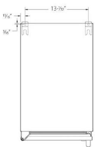
text_image
15/6" 3/6" 13-½"Figure 2A. 15" Anti-tip Kit

text_image
1½" 22 ½" 23 ¾" 3/6" ¾" ½" to hole 1 ¾" ¾"Figure 3. 48" Anti-tip Kit
Perlick
PERLICK RESIDENTIAL INSTALLATION MANUAL
PREPARING THE SPACE
CAUTION If the unit is to be installed under a countertop, it is recommended that the countertop be supported by a structure other than the unit itself to prevent damage to the unit.
CAUTION Make sure the floor under the unit is level with the surrounding finished floor. Protect a finished floor with plywood, cardboard, or some other suitable material before moving the unit into place. Failure to do this may result in damage to the floor.
1). Make sure the space opening is correctly sized for the unit. See chart below for finished rough opening requirements:
| HP15 15" Signature Series | ||
| Height Depth Width | ||
| 34-3/8" minimum,35-1/2" maximum | 24" 15" | |
| HP24 24" Signature Series | ||
| Height Depth Width | ||
| 34-3/8" minimum,35-1/2" maximum | 24" 24" | |
| HP48 48" Signature Series | ||
| Height Depth Width | ||
| 34-3/8" minimum,35-1/2" maximum | 24" 48" | |
| HH24 Signature Series Sottile | ||
| Height Depth Width | ||
| 32-1/2" 18" 24" | ||
| HC24 24" C-Series | ||
| Height Depth Width | ||
| 34-3/8" minimum,35-1/2" maximum | 24" 24" | |
| HA24 24" ADA-Compliant Series | ||
| Height Depth Width | ||
| 32-1/2" 24" 24" | ||
NOTE: For a cabinet door to open properly, the door must open a minimum of 90°. Use a minimum 3" filler in corner installations to assure a full 90° opening. Allow 25" clearance in front of unit for full door swing and shelf/drawer pull out for all units.
2). Check that the following are level and square:
- Front and interior opening
• Installation opening and floor surface - Countertop bottom front edge
NOTE: The floor under the unit must be at the same level as the surrounding finished floor.
⚠️ CAUTION To prevent possible damage to the countertop, do not place heavy objects on countertop directly over unit.
INSTALLING THE UNIT
1). Plug the unit into the 15 amp grounded electrical outlet located within the installation opening. With power applied to the unit, check that the lighting and cooling functions operate properly. Turn off the power to the wall outlet at the circuit breaker.
2). With all surfaces in the installation opening square and level, refer to Figure 4 on page 7 and perform the following steps to level the unit:
- At the front of the opening, measure from the floor to the bottom of the front edge of the countertop.
- Measure from the floor surface to the top of the unit at the rear corners.
- Adjust the unit legs so these two measurements are equal. Using an adjustable wrench or pliers, turn legs clockwise to lower the unit or counterclockwise to raise it.
NOTE: Legs should not extend more than 3/4" from the bottom of the unit.
3). Slide the unit into position in the opening. Make sure the rear leveling legs slide under the ant-tip brackets. Push the unit into the opening until the bottom front edge of the unit is flush with the surrounding cabinetry, or until the rear legs are tight against the anti-tip brackets.
4). Shim the front of the unit so the front face is flush with the surrounding cabinetry. Adjust the front legs to support the countertop at the shimmed height. Using an adjustable wrench or pliers, turn the legs clockwise to lower the unit or counterclockwise to raise it. Countertop should be resting on top of the unit.
NOTE: Countertop should be resting evenly on entire top of the unit. Shim if necessary to prevent damage to the countertop.
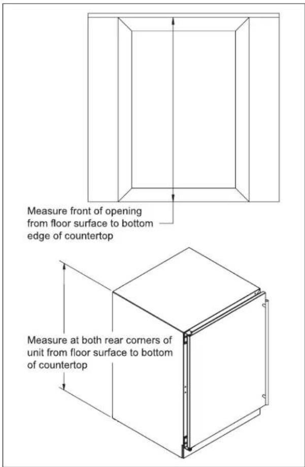
text_image
Measure front of opening from floor surface to bottom edge of countertop Measure at both rear corners of unit from floor surface to bottom of countertopFigure 4. Leveling the Unit
5). Check interior door openings to make sure the unit is level and square. Install shelving and/or drawers. Place the slide brackets squarely into the bracket grooves. When installed properly, a "click" should be heard from the slide bracket retaining tabs and the brackets should slide smoothly. The retaining tabs will stop the shelf/drawer when pulled out to full extension.
6). Turn on the power to the wall outlet at the circuit breaker.
NOTE: Improper shelf/drawer installation may not actuate slide mechanism.
TOE PLATE INSTALLATION
Once the unit is secured in place, install the louvered toe plate. Secure the plate by snapping the latch into the latch catch on the unit (Figure 5).
CAUTION
The toe plate must be removed to service the unit. The oor cannot
interfere with removal, and the louvered sections must not be covered or obstructed. Obstructions could prevent proper air circulation, which may damage the unit.
NOTE: To achieve maximum performance, interior louver openings and fan guard openings should never be obstructed.

text_image
Latch Strike LatchFigure 5. Toe Plate Installation
SHELVING/DRAWER ADJUSTMENTS
A CAUTION Completely empty shelf or drawer before removing.
- Pull the shelf/drawer out to its furthest position. Locate the tabs in the middle of both extenders. Lift one tab up while pushing the opposite tab down, and pull shelf/ drawer out (Figure 6).
- Position each bracket separately. Grasp the middle of the bracket, pull the front end up and out, then forward to remove it.
- Place bracket at desired location. Push the bracket rear hook into the rear mounting slot, then set front of the bracket in the front slot.
- Repeat for other brackets.
- Push extenders completely into brackets. Align the shelf/drawer grooves with the extenders and slide completely into the unit.
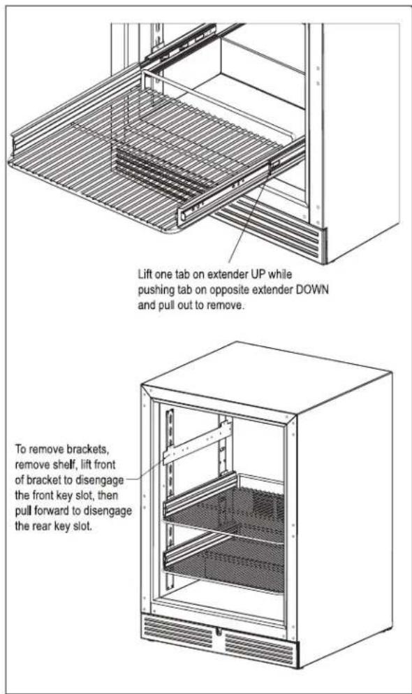
text_image
Lift one tab on extender UP while pushing tab on opposite extender DOWN and pull out to remove. To remove brackets, remove shelf, lift front of bracket to disengage the front key slot, then pull forward to disengage the rear key slot.Figure 5. Shelving/Drawer Adjustment
DOOR OPTIONS
Perlick residential units offer a variety of door panel design alternatives; solid stainless steel, solid wood overlay, glass with stainless steel trim and glass with wood overlay trim.
Solid stainless steel and stainless steel glass doors are shipped from the factory with decorative stainless steel panels and handles in place on the unit. Solid wood overlay and glass wood overlay doors are designed to accept a decorative front panel to match surrounding cabinetry and door handles.
NOTE: Wood overlay models are designed to accept wood overlay panels from your cabinetry supplier. They do not include a wood overlay. Templates are available on www.perlick.com/residential-products. Click on Service & Support, and then choose Wood Overlay Templates from the menu. Take care in choosing the correct template for your specific model. The handle is supplied by the customer.
All Perlick units (excluding beer dispenser and ice maker models) accept any of the above door configurations and are fully interchangeable. Glass door configurations are not available on beer dispenser or ice maker models.
NOTE: Glass with stainless steel trim and glass with wood trim may sweat in conditions with relative humidity over 75%.
CHANGING DOOR SWING DIRECTION
NOTE: Changing the door mount is not advisable if the door is equipped with a custom wood overlay. Doing so may result in an undesirable handle position.
To change the door swing direction, a hinge kit is required:
• Part No. 67439R - Right hinge kit
• Part No. 67439L - Left hinge kit
In addition to the hinge kit, the following tools are required:
• Large flat head screwdriver
• Regular Phillips head screwdriver
- Plastic putty knife
1). Support the door in the open position as shown in Fig. 7 on page 9. Remove the hinge pin.
2.) Pull door to the side and then lower door.
3.) Remove top and bottom hinge brackets. Retain screws for later use. See Fig. 8 on page 9.
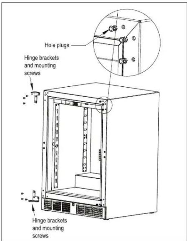
4). Remove the hole plugs from the top and bottom hinge bracket mounting holes (see Fig. 8 on page 9). Place the plugs in the holes on the opposite side made vacant by removing the hinges in step 3.
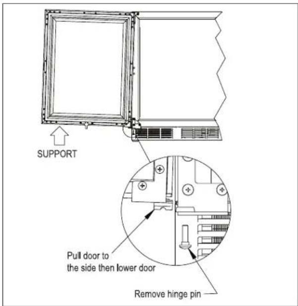
text_image
SUPPORT Pull door to the side then lower door Remove hinge pinFigure 7. Door Removal
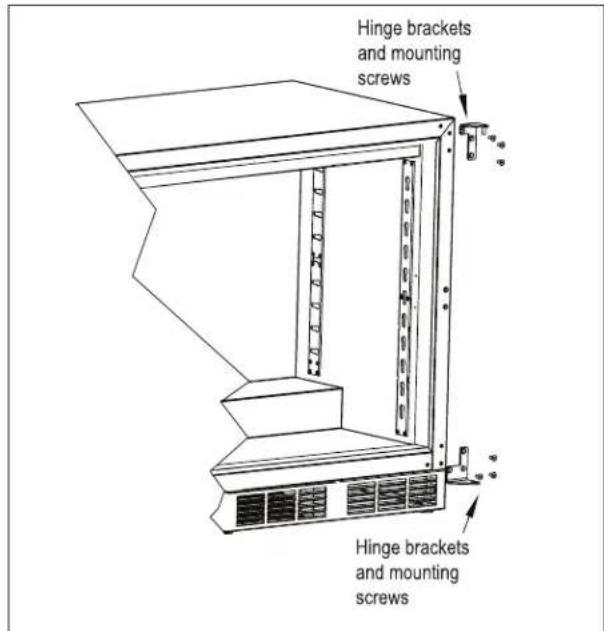
5). Using the screws removed in step 3, install the top and bottom hinge brackets from the kit (Fig. 9).
text_image
Hinge brackets and mounting screws Hinge brackets and mounting screwsFigure 9. Hinge Installation
text_image
Hole plugs Hinge brackets and mounting screws Hinge brackets and mounting screwsFigure 8. Hinge Removal
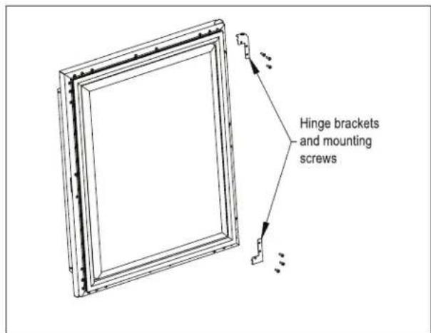
6). Remove the top and bottom door hinge brackets and the push plunger brackets (Fig. 10). Retain the screws for later use.
text_image
Hinge brackets and mounting screwsFigure 10. Door Brackets
Perlick
PERUCK RESIDENTIAL INSTALLATION MANUAL
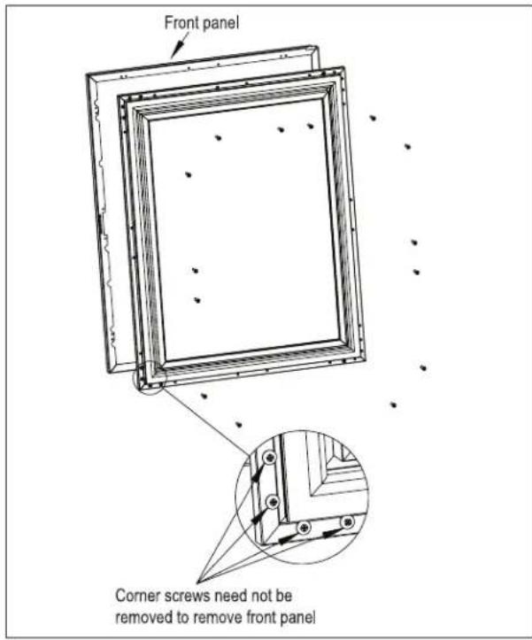
7). Remove the front panel from the door assembly by removing the door gasket and then removing the overlay mounting screws, 4 per side, from the perimeter of the door assembly (Fig. 11). Rotate the front panel 180°. The top becomes the bottom. Reattach using the same screws and mounting holes and then reinstall the door gasket.
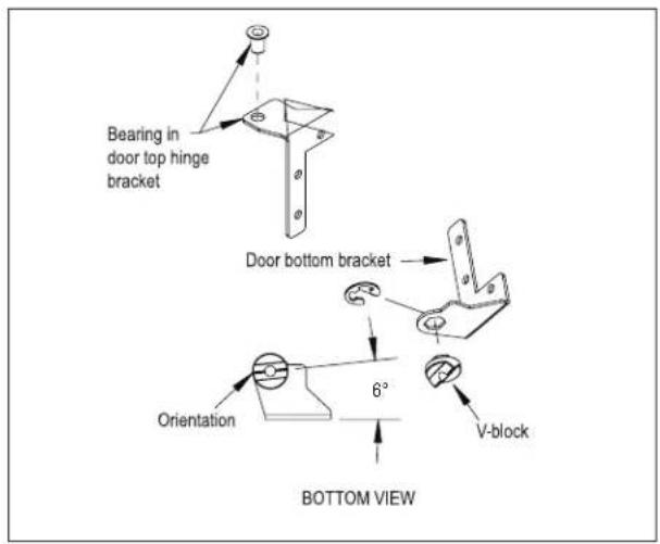
9). Insert the bearing into the door hinge bracket (Fig. 13).
10). Insert the V-block into the door bottom hinge bracket and attach with the e-clip (Fig. 13). Note the orientation of the V-block.
text_image
Front panel Corner screws need not be removed to remove front panelFigure 11. Removing Front Panel
text_image
Bearing in door top hinge bracket Door bottom bracket Orientation 6° V-block BOTTOM VIEWFigure 13. Bearing and V-Block
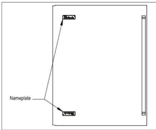
8). Remove the Perlick nameplate from the door front using a plastic putty knife (Fig. 12). Install the new Perlick nameplate included in the kit.
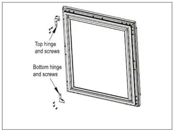
11). Attach the top and bottom hinges and push plunger using screws removed in step 6 (Fig. 14).
flowchart
graph TD
    A["Nameplate"] --> B["Component 1"]
    A --> C["Component 2"]
Figure 12. Nameplate
text_image
Top hinge and screws Bottom hinge and screwsFigure 14. Door Hinges
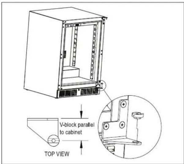
12). Place the lower V-block into the lower cabinet hinge with the notch parallel to the cabinet (Fig. 15).
text_image
V-block parallel to cabinet TOP VIEWFigure 15. Installing V-Block
13). Lift the door assembly and insert the top pin into the bearing. Move door toward cabinet and align the V-blocks (Fig. 16).
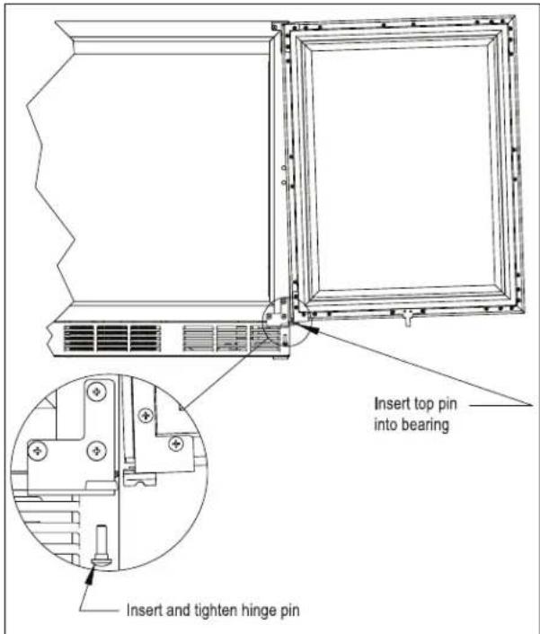
text_image
Insert top pin into bearing Insert and tighten hinge pinFigure 16. Installing Door
14). Insert and tighten the lower hinge pin to complete the assembly.
HANDLE INSTALLATION
CAUTION The handle mounting on the wood overlay should be mounted on the overlay only (not the actual door) to avoid damage to the factory door.
- Handle must be attached to the overlay before mounting the overlay onto the door. Mark the rear of the wood overlay panel with handle fastening locations.
- Drill through the wood overlay panel at marked locations, taking care not to damage the panel.
- Countersink screw heads so that screw heads are flush with the back side of the panel. Attach the handle to the overlay panel.
⚠ CAUTION Proper woodworking materials and equipment should be used to avoid damage or errors in workmanship.
DOOR LOCK INSTALLATION
NOTE: Full size lock installation wood overlay panel templates are available on the Perlick website. Visit www.perlick.com/Residential, click on Service & Support, and then choose Wood Overlay Templates from the menu. Lock templates are available for all HP, HC, HA and HH series models. Take care in choosing the correct template for your specific model.
When installing to a wood overlay, perform the lock installation before mounting the wood overlay to the door!
- See Figure 17 below. Attach mounting bracket to wood overlay.
- Insert lock body and attach with nut.

text_image
Mounting bracket Nut Lock strike Lockwasher Screw Lock body Lock bracket Figure 17. Installing Door LockWOOD OVERLAY INSTALLATION (FOR -2, -4 AND -6 MODELS)
Before beginning installation, check all components for proper fit and finish.
CAUTION
For best performance and functionality, the overlay panels should be 3/4" thick. The weight of the overlays should not exceed 20 lbs for solid (-2) doors, 10 lbs for glass (-4) doors, or 10 lbs for drawer (-6) models.
- With the unit secured in position, open the door, remove the door gasket and make sure panel pre-drilled holes align with door frame holes.
- Loosely attach four corners of overlay panel to the door using #10 x 3/4" wood screws, installed through the door frame from the rear.
- Check for overall wood overlay panel fit, position, and function. Make minor adjustments as necessary. When panel is properly aligned, tighten mounting screws securely. Install the rest of the mounting screws and tighten securely.
CAUTION
Do not overtighten wood overlay attachment screws, as this may be supplied door frame.
WINE RACK TRIM (OPTIONAL)
All wine reserve racks come with sleek stainless steel fronts. Unfinished solid hardwood fronts are optional and can be removed and replaced with other wood to match your cabinetry. See Figure 18 and 19 for wine rack face details.
NOTE: The unfinished faces should be finished and sealed. In many cases, stains and/or finishes have odors that may be objectionable in an enclosed area. Do not stain or finish wood faces while installed on unit. To remove the front wood face from the wine shelf, simply pull out the wine shelf and remove the fasteners, finish as desired, and when completely dry, reinstall with fasteners.
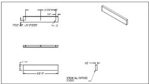
text_image
4.120°×4.957 95° 1732°×48' x 95° DEEP 1.12" 95°/5" 1/2" STREAK ALL OUTS DE EDGEFigure 18. Wine Rack Trim, 15" models
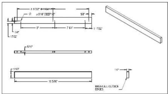
text_image
8 1732" 4+1500" x 916" CEDP-15" 58" 34" 1732" 7 10" 1 1732" 516" 1 12" 18 516" 20" BREAK ALL OUTSIDE EDGESFigure 19. Wine Rack Trim, 24" models

text_image
Perlick®QUALITY & INNOVATION
THAT INSPIRES
Use and Care Guides, Specification Sheets, Wood Overlay Templates for Doors, Drawers and Grilles, and Corresponding Compliance and Energy Guides are available for download at
www.perlick.com/residential-products/service-support.
Contact Perlick Customer or Technical Service at 800.558.5592.
Customer Service and Technical Service are available business days Monday through Friday from 7:00 a.m. to 7:00 p.m. CST.

8300 W. Good Hope Road, Milwaukee, WI 53223 • 800.558.5592 • info@perlick.com • www.perlick.com