
CR24D-1-4L - Jokofu Perlick - Free user manual and instructions
Find the device manual for free CR24D-1-4L Perlick in PDF.

| Product Type | Undercounter Beverage Center |
| Brand | Perlick |
| Model | CR24D-1-4L |
| Width | 24 inches (61 cm) |
| Height | 34.5 inches (87.6 cm) |
| Depth | 24 inches (61 cm) |
| Weight | 108 lbs (49 kg) |
| Power Supply | 115V / 60Hz, 2.5A |
| Temperature Range | 34°F to 50°F (1°C to 10°C) |
| Shelves | 4 adjustable wire shelves |
| Door Type | Full-height glass door with stainless steel frame |
| Interior Light | LED with on/off switch |
| Thermostat | Digital, with external display |
| Defrost | Automatic |
| Lock | Key lock included |
| Leveling Legs | 2 front leveling legs |
| Installation Type | Built-in or freestanding |
| Cleaning | Wipe interior and exterior with damp cloth; mild soap if needed |
| Replacement Parts | Contact Perlick customer service or authorized parts distributor |
| Warranty | 1 year parts and labor (check manual for details) |
Frequently Asked Questions - CR24D-1-4L Perlick
User questions about CR24D-1-4L Perlick
0 question about this device. Answer the ones you know or ask your own.
Ask a new question about this device
Download the instructions for your Jokofu in PDF format for free! Find your manual CR24D-1-4L - Perlick and take your electronic device back in hand. On this page are published all the documents necessary for the use of your device. CR24D-1-4L by Perlick.
USER MANUAL CR24D-1-4L Perlick
natural_image
Exterior view of a modern stainless steel double-chamber refrigerator with illuminated shelves and glass doors (no visible text or symbols)
Installation
& Operation Manual
Wine Column Refrigeration
Commercial
Model CC24W Series
Model CC24D Series
Residential
Model CR24W Series
Model CR24D Series
Model CC24W-1-4R/CR24W-1-4R Shown
TABLE OF CONTENTS
General Information....2
Opening/Niche Dimensions 5
Placement and Alignment of Appliance 10
Anti-Tip Bracket 11
Installing Door Overlay Panel....13
Door Trim Installation....16
Grill Installation....17
Air Filter Installation....18
PerliQ Digital Control Operation 19
Stainless Steel/Surface Care....22
Use and Care Information 23
Warranty 25
GENERAL INFORMATION
Introduction
Congratulations on your purchase of a Perlick commercial wine column refrigerator. This manual has been prepared to assist you in the installation of your column refrigerator and to acquaint you with its operation and maintenance.
We dedicate considerable time to ensure that our products provide the highest level of customer satisfaction. If service is required, your dealer can provide you with a list of qualified service agents. For your own protection, never return merchandise for credit without our approval.
We thank you for selecting a Perlick product and assure you of our continuing interest in your satisfaction.
Product Information
Additional product information, such as installation instructions, Use and Care Guides, Spec Sheets, CAD Drawings, Compliance Documentation and product warranty information can be referenced or downloaded at perlick.com.
Warranty Registration
To register your product, visit our web site at www.perlick.com. Click on "Commercial", then "Resources", then "Use and Care", and then "Warranty Registration Form". You must complete and submit this form or the installation date will revert back to the ship date.
Please record the purchase date and the dealer's name, address and telephone number below.
Model Number: ____
Serial Number: ____
Purchase Date: ____
Dealer Name & Address
Phone Number
NOTE: See page 20 for full warranty details.
Product Identification Plate
Your product information can be found on the product's identification plate. The identification plate is located on the sidewall behind the toe kick plate. To access the identification plate, simply remove the toe kick plate (grill). The identification plate will be adhered to the right sidewall.
SAFETY
PLEASE READ all instructions completely before attempting to install or operate the unit. Take particular note of the DANGER, WARNING an CAUTION information in the manual. The information is important for the safe and efficient installation, operation and care of your Perlick unit.
DANGER
Indicates a hazard that WILL result in serious injury or ns are not followed.
WARNING
Indicates a hazard MAY cause serious injury or s are not followed.
death if precautions are not followed.
CAUTION
Indicates a hazard where minor injury or product is if precautions are not
damage may occur if precautions are not followed.
NOTICE
Indicates that property damage may occur if
warnings or instructions are not followed.
IMPORTANT!
Read and understand all information in this manual before attempting the installation. All electrical work must be performed by a qualified technician and conform to all applicable state and local codes.
SITE PREPARATION
WARNING
Carefully inspect the cabinet for hidden damage. If
damage is discovered, file your claim immediately with the transportation company. Perlick is not responsible for damage in transit.
CAUTION
When moving the unit, be sure to protect finished
flooring with appropriate material to avoid damage from moving the appliance.
CAUTION
If unit has been laid on its back or sides, place unit
upright and allow minimum of 24 hours before connecting the unit. Failure to do so can affect the function and performance of the appliance.
This appliance should be installed in a dry, ventilated indoor location. The ambient temperature of the location must be between 55^ F ( 13^ C) and 100^ F ( 43^ C) for optimal performance.
When fully stocked, Perlick wine column refrigeration is very heavy. To ensure safety and prevent home damage, the load-bearing capacity of your floor must be 550 lbs for each CC24W column being installed.
This product must be installed on a level floor for safety and optimal performance. The base must be flat to ensure anti-tip brackets properly function and that the refrigeration system is level. Any walls and surrounding furniture/fixtures need to be securely attached to the floor, wall studs or concrete prior to installing the column.
To ensure proper performance, the air intake (toe kick) must not be blocked. Perlick refrigeration is front-breathing, and covering the intake will cause the system to overheat and fail.
PRIOR TO INSTALLATION
Safety Precautions

Inspect the electrical cord and plug for damage prior
to plugging the unit in.

If service is necessary, repair work must be
performed by a Perlick authorized servicer. Work done by unqualified individuals could potentially be dangerous and will void the warranty.

If unit has been laid on its back or sides, place unit
upright and allow minimum of 24 hours before connecting power. Failure to follow this procedure may damage the compressor and void the warranty.

Do not use or store flammable liquids (ie;
gasoline) or vapors near the appliance.

Perlick columns are top heavy. It is important that it
is secured at all times with the door closed until installed. Install as directed using anti-tip brackets provided to prevent tipping.

Take special care when moving to prevent injury.
Electrical

Serious electrocution hazard. Electrical
grounding is required. This appliance is equipped with a 3-prong (grounding) polarized plug for your protection against possible shock hazards. Failure to comply with these electrical guidelines may result in possible death or serious injury, fire or loss of property.

Never use an extension cord to connect the unit to
the electrical source. Do not use a two-prong adapter or remove the power cord ground prong.
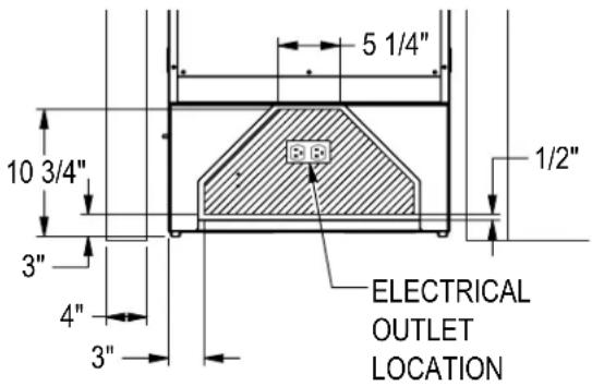
Installation must comply with all applicable electrical codes. The electrical supply must be located within the shaded area of the illustration below. A separate circuit, servicing only this appliance, is required. A ground fault circuit interrupter (GFCI) is not recommended and may cause interruption of operation. The outlet should be placed in the hatched area dimensioned below.
| Electrical Supply 1 | 15V, 60Hz., Phase 1, 3.3 amps |
| Service Dedicated | 15 amp circuit |
| Power/Cord Type/Length | NEMA 5-15P w/5' power cord |
NOTICE
This product contains blown foam insulation
using blowing agent R-611 (Methyl Formate). The foam in this product does not contain HFC's, CFC's, or HCFC's.
INSTALLATION
Installation Tools and Materials
- Screwdrivers (standard Phillips.)
- Power Drill
- Drill bits (masonry bits required for concrete installation)
- Standard socket, wrench and 1/2" socket
- 2' and 4' levels
- Material to protect flooring and surrounding cabinetry
For Built-In Applications
Opening Dimensions
The depth of each Perlick column is 24" (610) to door face (not including the 3/4" overlay). Allow for door panel thickness when planning the finished opening depth. A minimum of 4" (102) finished return is required on all sides of the opening. See below for opening dimensions drawing.
It is important that the side walls of the niche are plumb prior to installation. The minimum thickness of both the side walls and the top wall must be 5/8" (16). The minimum thickness of the toe kick panel must be 1/2" (13). A thickness of 3/4" (19) is recommended.
Framed cabinets will require additional filler material behind the face frame for attaching anti-tip brackets. Refer to the illustration below.
![84" [2134] 25" [635] 24" [610] 23 3/4" [603] OVERALL 22 1/8" [562] TO CABINET 21 9/16" [547] TO GRILL 24" 3/4" [629] [610] OVERALL TO FRONT OF DOOR FACE 3/4" [19] OVERLAY 83 7/8" [2131] OVERALL 4" [102] TO 6" [153] TOE KICK](/content/2026/06/1192852/images/788f2c78840355f28630a7711388cea007306dc66194174da6e36f897329a439.jpg)
![SIDE WALL CABINET DOOR FILLER MATERIAL 24" [610] FRAME FACE 4" [102]](/content/2026/06/1192852/images/c66c8973dc60700d39845ed1665e01a5c11682fb841f03e070874b13d6e487dc.jpg)
5 Printed in USA
INSTALLATION CONTINUED
ADJACENT WALL OR STRUCTURE MINIMUM CLEARANCE REQUIREMENTS

WHEN BUILDING INTO STRUCTURE OR NEXT TO ADJACENT WALLS REFERENCE THIS DRAWING FOR MINIMUM REQUIRED CLEARANCES TO AVOID INTERFERENCE WHEN OPENING THE DOOR(S).
THE ADJACENT STRUCTURE CLEARANCES INDICATED ARE BASED ON A STANDARD PERLICK HANDLE INSTALLED ON THE DOOR OVERLAY.
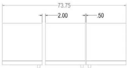
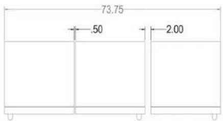
MINIMUM SPACING REQUIRED BETWEEN ADJACENT CABINETS TO AVOID DOOR SWING INTERFERENCE.
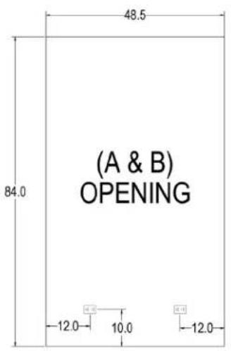
(A) 2 Cabinets HANDLE TO HANDLE.
Refer to (A&B) Opening diagram (page 8) for finished opening dimensions and outlet locations.

(A) HANDLE TO HANDLE
(B) 2 Cabinets HINGE TO HINGE.
Refer to (A&B) Opening diagram (page 8) for finished opening dimensions and outlet locations.

(B)HINGE TO HINGE
INSTALLATION CONTINUED
MINIMUM SPACING REQUIRED BETWEEN ADJACENT CABINETS TO AVOID DOOR SWING INTERFERENCE CONTINUED.
Opening Dimensions
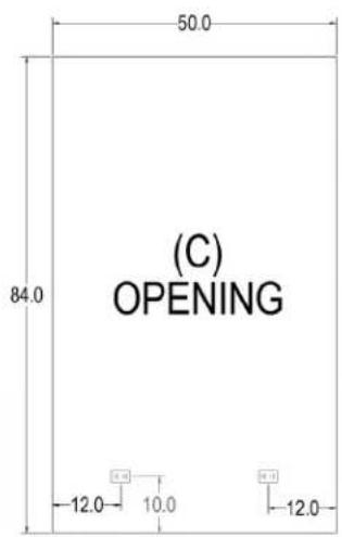
(C) 2 Cabinets HANDLE TO HINGE.
Refer to (C) Opening diagram (page 8) for finished opening dimensions and outlet locations.
(C) HANDLE TO HINGE
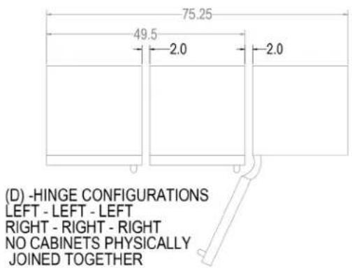
(D) 3 Cabinets with Hinges either all left or all right.
Refer to (D) Opening diagram (page 8) for finished opening dimensions and outlet locations.
(E) 3 Cabinets with Hinges Left-Right-Left or Right-Left-Right.
Refer to (E) Opening diagram (page 9) for finished opening dimensions and outlet locations.
(E) - HINGE CONFIGURATIONS
LEFT - RIGHT - LEFT
RIGHT - LEFT - RIGHT
ALL CABINETS PHYSICALLY
JOINED TOGETHER
(F) 3 Cabinets with Hinges Left-Left-Right or Right-Right-Left.
Refer to (F) Opening diagram (page 9) for finished opening dimensions and outlet locations.
(F) - HINGE CONFIGURATIONS
LEFT - LEFT - RIGHT
RIGHT - RIGHT- LEFT
(2) CABINETS PHYSICALLY JOINED TOGETHER
INSTALLATION CONTINUED
MINIMUM SPACING REQUIRED BETWEEN ADJACENT CABINETS TO AVOID DOOR SWING INTERFERENCE CONTINUED.
(G) 3 Cabinets with Hinges Right-Left-Left or Left-Right-Right.
Refer to (G) Opening diagram (page 9) for finished opening dimensions and outlet locations.
(G) - HINGE CONFIGURATIONS
RIGHT - LEFT - LEFT
LEFT - RIGHT - RIGHT
(2) CABINETS PHYSICALLY JOINED TOGETHER
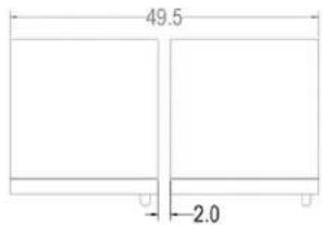
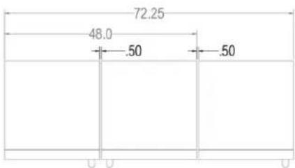
FINISHED OPENING DIMENSIONS FOR 2 AND 3 UNIT INSTALLATIONS.

INSTALLATION CONTINUED
FINISHED OPENING DIMENSIONS FOR 2 AND 3 UNIT INSTALLATIONS CONTINUED.
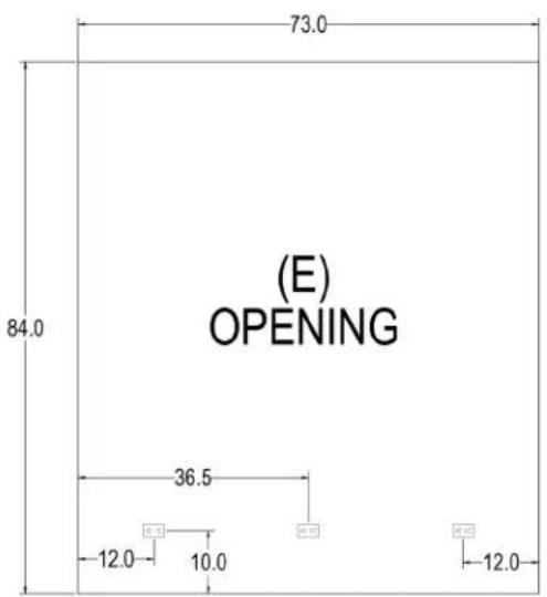

Note:
For installations involving more than 3 cabinets, combine opening dimensions for the openings which correspond to the combined Hinge and Handle configurations.
PLACEMENT & ALIGNMENT
CAUTION
Before moving the unit into position, secure the door closed and protect any finished flooring.
WARNING
If the unit has been on its back, it must stand upright for a minimum of 24 hours before connecting power.
Move the unit near the opening. Plug the power cord into the grounded outlet and roll the unit into position. Push unit into place.
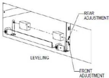
Leveling
Front and rear leveling legs can be adjusted from the front once the unit is positioned.
NOTE: Remove grill to access leveling adjustment access holes.
Once the unit is in position, height adjustment can be made from the front. Using the hex driver leveling tool, turn clockwise to raise the unit or counterclockwise to lower. Refer to the illustration below.
When the unit is properly leveled, door adjustments are less likely to be necessary.
CAUTION
Level the unit to the floor, not surrounding cabinetry.
This could affect the operation of the unit, such as door closing.
WARNING
To reduce the possibility of the unit tipping forward, the front leveling legs must be in contact with the floor.

natural_image
Person standing on a concrete floor next to an industrial machine (no visible text or symbols)Adjusting front leveling legs.
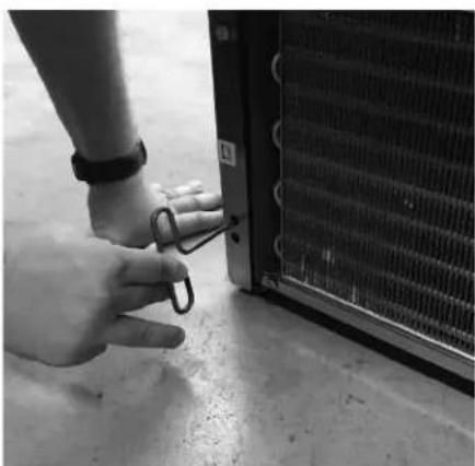
natural_image
Close-up of a hand holding a small metal clip next to a large heat exchanger or cooling unit (no visible text or symbols)Adjusting rear leveling legs.
LEVELING THE UNIT

ANTI-TIP BRACKET
The anti-tip bracket and supporting hardware is included with your unit. In the case of dual installation, each individual unit must be outfitted with the included anti-tip brackets.
For drawings of the anti-tip bracket installation on integrated unit, see below. For drawings of the anti-tip bracket installation on freestanding units, see page 8.
CAUTION
Always wear safety glasses and use other necessary protective devices or apparel when installing or working with anchors. Anchors are not recommended for use in lightweight masonry material such as block or brick, or for use in new concrete which has not had sufficient time to cure. The use of core drills is not recommended to drill holes for anchors.
WARNING
Verify there are no electrical wires or plumbing in the area which the screws could penetrate.
Anti-Tip Bracket Installation for Built-In Applications
NOTE: Do not fasten anti-tip brackets to adjacent cabinetry until the cabinet has been leveled.
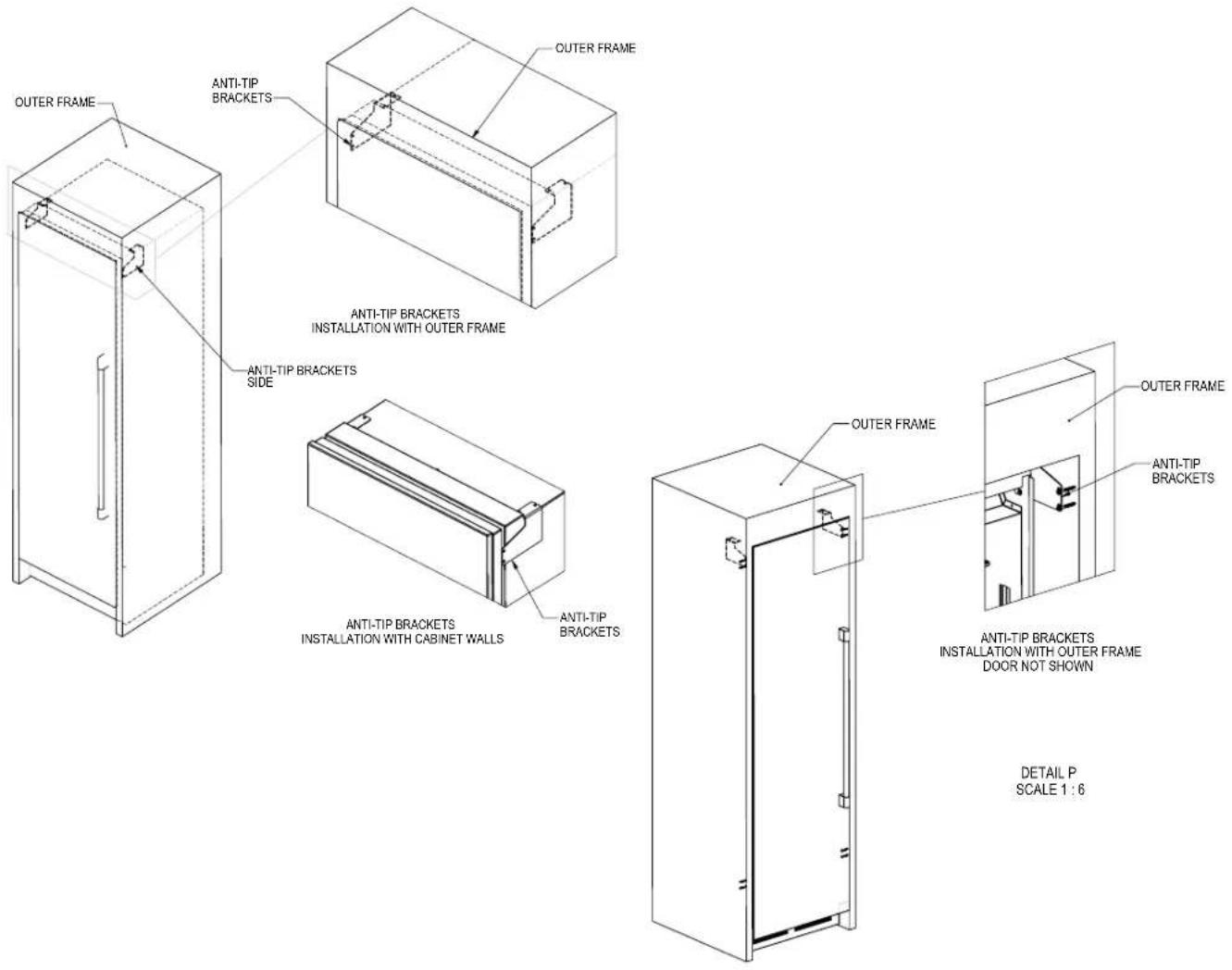
Anti-Tip Application for Freestanding Applications
NOTE: Cabinet must be leveled before securing to wall with anti-tip bracket.
![with anti-tip bracket. ANTI TIP BRACKET TOP ANTI TIP BRACKETS TOP AND BACK 1 1 1/2" [38] WALL ANTI TIP BRACKET TOP AND BACK DETAIL D SCALE 1 : 3](/content/2026/06/1192852/images/a126619c8479fa2a02fdf762c4c6c9be924134f53569e5e18d64486447fda649.jpg)
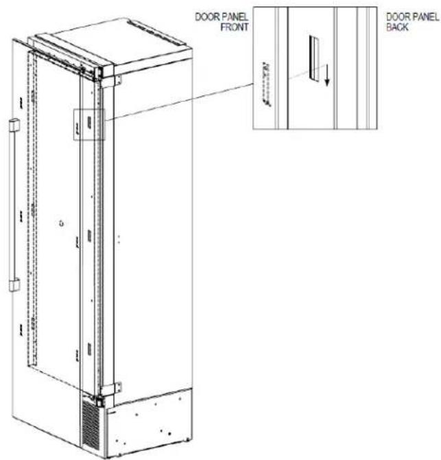
INSTALLING DOOR OVERLAY PANELS
Typical panel dimensions are based on 84" (2134) finished height with 1/8" (3) reveals. Template must be adjusted for panels exceeding typical dimensions.
Place the panel face down on a protected work surface. Attach six clips to the back of overlay in locations indicated in wood overlay drawing.
Use provided #10 x 1/2" screws to attach clips to overlay. Overlay then slides onto door face. Attach overlay to door adjustment brackets using remaining #10 x 1/2" screws. Once mounted, adjust overlay to match adjacent cabinetry.
CAUTION
As the reveal between cabinets and the unit decreases, the potential exists for severe finger pinching if fingers are placed in the opening when door is closing.

4" Toe Kick Wood Overlay Template Glass Door
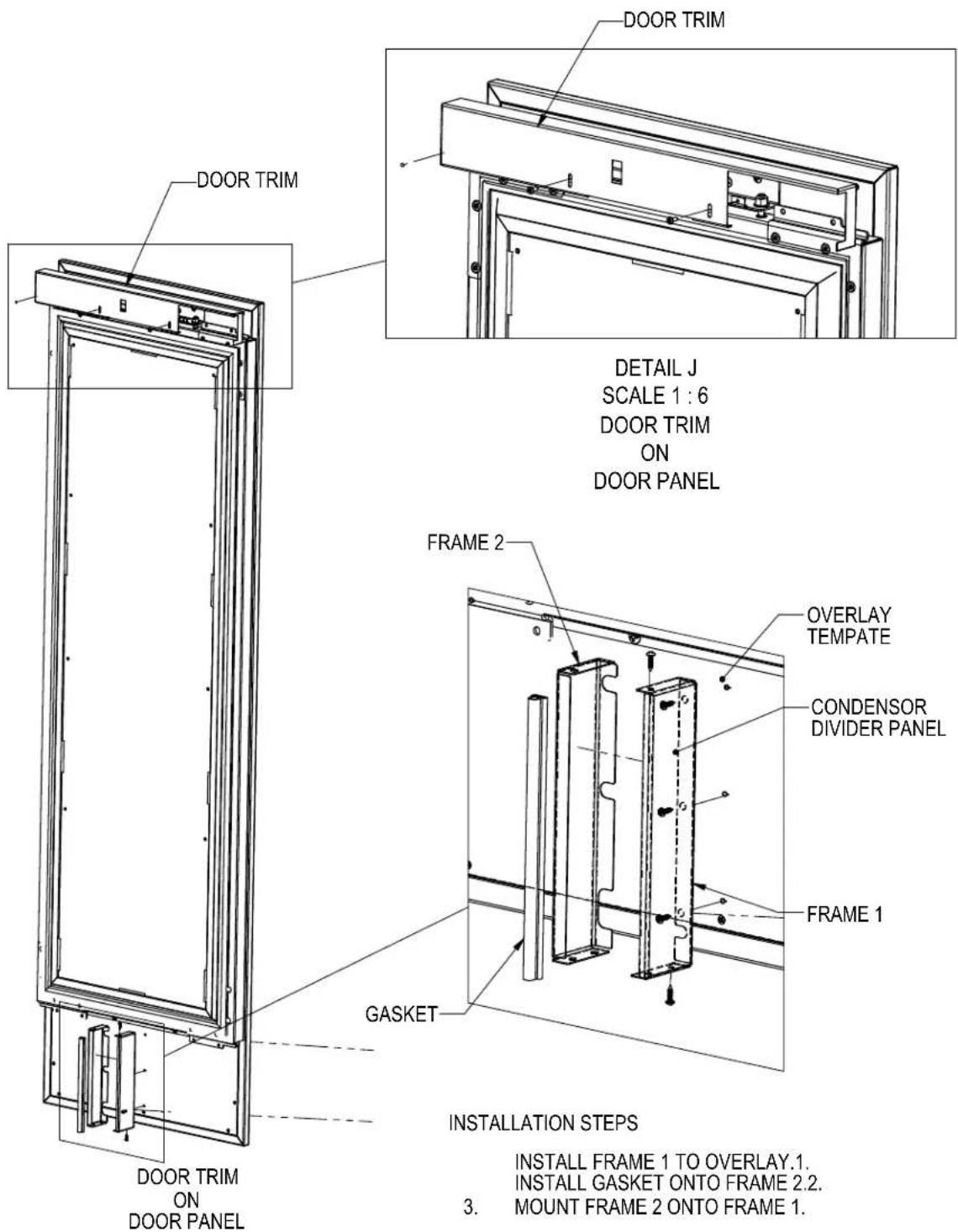
INSTALLING DOOR OVERLAY PANELS CONTINUED
Custom Overlay Panels
A custom door panel and handle hardware must be installed. The thickness of the custom panel can vary. A minimum 5/8" (16) thick panel is required, but the thickness can be increased provided it does not exceed the maximum panel weight of 65 lbs (29). 3/4" panel is recommended. Please note that the combined door and overlay weight cannot exceed 120 lbs (54). The depth of each model is 24" (610). Allow for panel thickness when planning the finished opening depth. Templates for solid and glass door models can be found on page 9.
CAUTION
As reveals between cabinetry and the unit
decrease, severe finger pinching can occur while the door is closing.
The height of the custom door panel can extend beyond the typical panel height provided it does not exceed the weight limit listed above.
CAUTION
Do not install a solid overlay panel onto the
front of a glass door model. Condensation will form between the glass and the overlay panel, which will cause damage to custom cabinetry.
Side Panels
Custom panels can be built to customer specifications to match surrounding cabinetry.
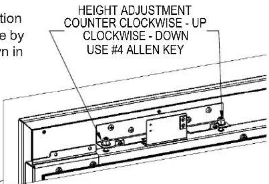
DOOR OVERLAY PANEL ADJUSTMENT
Close the door to make adjustments to align panels and reveals.
For up-and-down adjustments, turn the height adjustment screws in the top bracket in and out. Adjust the screws as needed to achieve an even reveal on each side of the door overlay.
Once final adjustments are made to the position of the door overlay, secure the overlay in place by installing the bottom overlay bracket as shown in BOTTOM OF DOOR illustration below.
Top Of Door
HEIGHT ADJUSTMENT COUNTER CLOCKWISE - UP CLOCKWISE - DOWN USE #4 ALLEN KEY

natural_image
Technical line drawing of a rectangular frame with mounting brackets and internal components (no text or symbols)Bottom Of Door

DOOR TRIM INSTALLATION
Once overlay is adjusted, mount the door trim bracket onto the door adjustment bracket using the provided screws.
DETAIL K SCALE 1:4
COMPLETION - GRILL INSTALLATION
Install the grill by snapping into latch catches.

TOE KICK CLEARANCE
![24 3/4" [829] OVER ALL 3/4" [19] OVERLAY 24" [610] TO FRONT OF DOOR FRAME DOOR PANEL 83 7/8" [2130] TO CABINET BASE TOE KICK CLEARANCE 24" [610] TO BACK OF UNIT HINGE DOOR PANEL LOUVERS FOR VENTS 4" [102] TO](/content/2026/06/1192852/images/eb729a74cd300fec08619f624ce60c9ac5e5d352fd1d9d0e0641014ebbe486a2.jpg)
17 Printed in USA
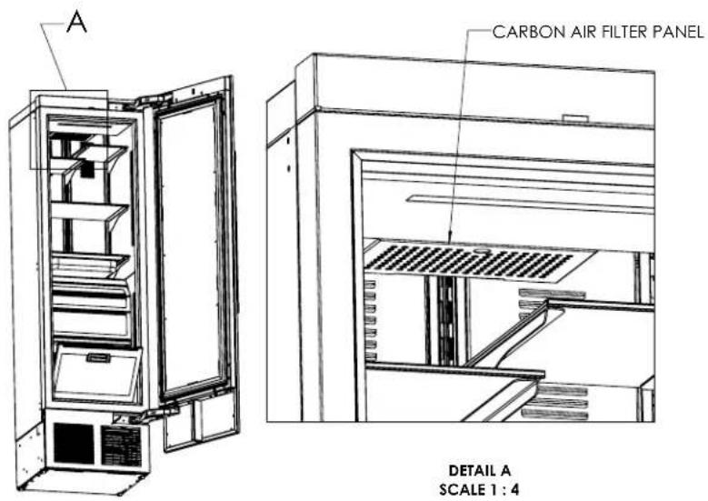
INSTALLING AIR FILTERS
Carbon Air Filter
The carbon air filters should be placed on the perforated panel located in the top-rear of the cabinet.
NOTE: The top wine rack will need to be removed to access the filter.
- Remove the filter from the plastic bag before installing into the unit. Do not open or puncture the tyvek bag.
- To lower the carbon air filter panel, pull firmly.
- Place the carbon air filter directly onto the panel and close panel - push firmly to engage closure clips.
- It is recommended that the carbon filter be replaced every 6 months.

WINE COLUMN DIGITAL CONTROL OPERATION
WINE COLUMN DIGITAL CONTROL OPERATION
The following instructions are for the PerIIQ ^™ digital controller in Perlick column wine reserves (models CC24W and CC24D).

1 Wake Button
2 Temperature zone selection (Dual-zone models)
3 White wine temperature setting
4 Red wine temperature setting
5 Cellar temperature setting
6 Temperature adjustment (up and down in 1° increments)
7 Temperature readout
8 Light adjustment (door open)
9 Light adjustment (door closed)
10 Light intensity adjustment
11 Fahrenheit temperature mode
12 Celsius temperature mode
13 Sabbath mode
14 QuickCool mode
15 Settings menu
Using the Wine Column Control
Upon door opening, the Wake button (1) outline will illuminate. Once activated, the temperature zone selection (2), temperature adjustment (6), temperature readout (7) and settings (15) menu icons will illuminate.
Selecting a Temperature Zone
Perlick's PerllQ™ digital controller is preset with recommended temperature settings for white wine, red wine and cellaring. Within the presets, you have the ability to adjust the temperature in 1° increments as you desire. Because single zone models (CC24W) are one temperature throughout, there is no zone selection. On dual zone models (CC24D), press the temperature zone selection (2) icon to toggle through the zones until desired zone is illuminated. Single zone models come factory set to 50°F. Dual zone models come factory set to 60°F in the top zone and 50°F in the bottom zone.

Top Zone

Bottom Zone
NOTE: Dual Zone Wine Upper compartment temperature setpoint must always be set at or above the lower compartment setpoint.
Storing White Wine
Perlick wine columns are preset with expert-recommended temperature settings for white wine. To set a zone in dual zone models to this preset, touch the temperature zone selection icon (2) to illuminate the zone you'd like to set to white wine temperature, then choose the white wine temperature setting icon (3) to set. For single zone models, simply choose the white wine temperature setting icon (3).
| Compartment | Sp. Factory Setting Temperature Range | |
| Any 50°F 40°F | -68°F | |
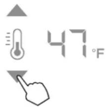
To adjust the temperature up or down, press the temperature adjustment (6) arrows until desired temperature is reflected in the temperature readout (7). Double beep indicates that minimum or maximum temperature has been reached. Temperature will flash twice to indicate new setting.
Storing Red Wine
Perlick wine columns are preset with expert-recommended temperature settings for red wine. To set a zone in dual zone models to this preset, touch the temperature zone selection icon (2) to illuminate the zone you'd like to set to red wine temperature, then choose the red wine temperature setting icon (4) to set. For single zone models, simply choose the red wine temperature setting icon (4).
| Compartment $p. Factory Setting Temperature Range | |||
| Any 60°F 40°F | -68°F | ||

To adjust the temperature up or down, press the temperature adjustment (6) arrows until desired temperature is reflected in the temperature readout (7). Double beep indicates that minimum or maximum temperature has been reached. Temperature will flash twice to indicate new setting.
Cellaring Wine
Perlick wine columns are preset with expert-recommended temperature settings for cellaring (long-term storage) wine. By choosing the cellar mode, the entire cabinet will default to 55^ F for long-term storage. For dual zone models, touch the temperature zone selection icon (2) to illuminate, then choose the Cellar temperature setting icon (5) to set. For single zone models, simply choose the Cellar temperature icon (5).
| Compartment | Sp. Factory Setting Temperature Range | |
| Any 55°F 40°F | -68°F | |
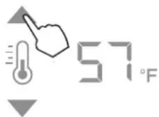
To adjust the temperature up or down, press the temperature adjustment (6) arrows until desired temperature is reflected in the temperature readout (7). Double beep indicates that minimum or maximum temperature has been reached. Temperature will flash twice to indicate new setting.
Column Theatre Lighting
Perlick column wine reserves feature an impressive amount of lighting for clear viewing and display of wine bottles. Main lighting, which can be changed from white to blue, runs vertically down the wall, and display lighting runs horizontally across the ceiling of the unit. Dual zone models also have display lighting on ceiling of the lower zone.

natural_image
Two symbolic icons: a lightbulb with arrows pointing upward and a light bulb with downward arrows pointing down, both without any text or symbols.Wine models are factory set to white lighting. To adjust the brightness of the lighting when the door is opened, press the up and down arrows in the light intensity adjustment icon (4). To change to blue lighting, continue pressing the arrows until the control turns blue in color. To return to white lighting, continue pressing the arrows until controls illuminate white. Icons will flash twice to confirm color setting.
Changing from Fahrenheit to Celsius scale
The controller is factory set to Fahrenheit scale, but can easily be changed to read Celsius in the settings menu.


Press the settings menu (15) icon on the far right. This will illuminate a cluster of four icons as shown to the left. To display temperatures in Celsius, press the Celsius readout icon (12).
Change will be reflected in the temperature readout (7). The C will be illuminated to signify the scale.
Quick Cool (Shopping) Mode
The wine column can be set to Quick Cool (shopping) mode to lower the temperature after loading a large quantity of product to quickly bring them to the preferred temperature.
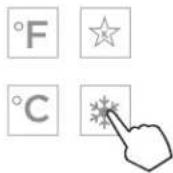
Press the settings menu (15) icon on the far right. This will illuminate a cluster of four icons as shown to the left. To activate Quick Cool (shopping) mode, press the Quick Cool (14) icon. This will activate the mode and the Quick Cool (14) will remain illuminated until the set point is achieved.
Sabbath Mode
All Perlick column refrigeration models have Sabbath mode capabilities. This allows the user to interact with the unit without changing the amount of energy it is using. In this mode, the interior lighting is turned off until user turns off Sabbath mode.
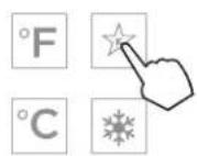

Press the settings menu (15) icon on the far right. This will illuminate a cluster of four icons as shown to the left. To activate Sabbath mode, press the Sabbath mode icon (13).
Please note that, when in Sabbath mode, the Sabbath mode (13) icon will be the only icon that will be illuminated (continuously) until user presses the Sabbath mode icon to turn the mode off.
Showroom Mode
Select Showroom mode for units that are being used solely for display purposes. Showroom mode has the user interface fully functional along with the cabinet lights, however, the refrigeration unit will be shut down.


Press the settings menu (15) icon on the far left. This will illuminate a cluster of four icons as shown to the right. To activate Showroom mode, press the Sabbath mode icon (13) and Quick Cool mode icon (14) simultaneously.
STAINLESS STEEL CARE AND CLEANING
Perlick's stainless steel surfaces are food grade, 304 stainless steel. Stainless steel is a "passive" metal because it contains other metals like Chromium, Nickel and Manganese that stabilize the atoms. Chromium provides an invisible film that covers the steel surface, acting as a shield agent against corrosion. As long as the film is intact and not contaminated, the metal is passive and stainless. If the passive film of stainless steel has been broken, the surface can start to corrode or rust.
Three materials or processes can break down stainless steel's passive layer, allowing corrosion to occur.
- Mechanical Abrasion This refers to items that will scratch stainless steel surfaces. Steed pads, wire brushes and scrapers are prime examples.
- Water Water that comes out of the faucet in varying degrees of hardness. Hard water may leave spots. When allowed to sit, these deposits will break down the passive Chromium layer and rust stainless steel. Other deposits from food preparation must be promptly removed with an appropriate cleaning agent.
- Chlorides Chlorides are found everywhere. They are in water, food and table salt. Household and industrial cleaners are the worst offenders.
Preventing Stainless Steel Rust
Use non-abrasive tools to clean stainless steel surfaces. Soft cloths and plastic scouring pads will not harm the steel's passive layer.
Clean with polish lines. Some stainless steels have visible polishing lines or "grain". When visible lines are present, always scrub in a motion parallel to the lines. When the grain cannot be seen, polish in a consistent straight pattern - not in a circular motion.
Use alkaline, alkaline chlorinated or non-chloride containing cleaners. While many traditional cleaners are loaded with chlorides, the industry is providing an ever-increasing choice of non-chloride cleaners. If you are not sure of chloride content in the cleaner being used, contact your cleaner supplier. If you present cleaner contains chloride, ask your supplier for an alternative. Avoid cleaners containing quaternary salt; it also can attack
stainless steel and cause pitting and/or rusting. Clean frequently to avoid build-up of hard, stubborn stains.
Stainless Steel Exterior Door Cleaning
Keep exterior stainless steel surface pristine by wiping the door with a damp microfiber cloth, followed by a dry polishing chamois. Always follow the grain direction when cleaning.
BLACK METALLIC SURFACE CARE AND CLEANING
Perlick's black metallic surface is finished with powder coat. When properly cared for, powder coating provides a durable, uniform finish that is resistant to scuffing, scratching or staining.
The following surfaces are black metallic:
- Wine Models Wine Shelf Fronts
To clean the black metallic surface:
- Carefully remove any loose debris with a damp sponge.
- Use a soft cloth and a mild household detergent solution to remove deposits.
- Wipe area with soft cloth and clean water. Dry thoroughly.
WINE STORAGE
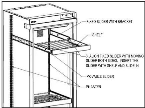
Wine Shelving
- Prior to making shelf adjustments, clear the shelf of product. Shelf must be empty prior to changing its position.
To Remove Wine Shelves


To Install Wine Shelves

AIR FILTRATION SYSTEM
We recommended changing the air filters every 6 months for optimum performance. Filters can be purchased through your local authorized Perlick dealer.
Carbon Air Filter
The Carbon air filter removes odor, bacteria and mold spores from the air.
To remove the Carbon air filter in CC24W and CC24D Wine units, refer to page 14 - carbon air filter.
WARRANTY
The terms and conditions set forth below together with those appearing on the face of the Acknowledgement (the “Order”) constitute the complete and exclusive agreement between Perlick Corporation and the Buyer pertaining to the goods and/or services identified in the Order. If there is a discrepancy or conflict between any exhibit or supplement to the Order and these terms and conditions, these terms and conditions shall control. The Order is intended by Seller and Buyer to be the complete, exclusive, and final statement of their agreement. Any changes to an Order must be in writing and signed by Perlick and Buyer.
TERMS NET 30 DAYS
Payment by Visa, MasterCard, American Express or Discover card accepted or cash in advance unless prior accommodations have been made with our Credit Department. Please direct inquiries for detailed information to our Credit Manager. All sales, excise, or similar taxes required by law to be collected or paid by seller shall be in addition to prices quoted unless an appropriate Tax Exemption certificate is furnished. All goods are sold F.O.B. factory. Except for otherwise provided, Perlick will not be responsible for freight, transportation, insurance, shipping, storage, handling, demurrage or similar charges. Invoices are payable in full in thirty (30) days following the invoice,s date of issuance. If by the terms of sale credit is extended, Perlick reserves the right to revoke such credit if buyer fails to pay for any products when due and may demand payment prior to the commencement of any further shipment.
WAIVER
Any waiver of strict compliance with the provisions of an Order must be in writing. No such waiver shall be construed as a waiver of any other term or condition except as provided in writing, nor as a waiver of any subsequent breach of the same term or condition.
METHOD OF SHIPMENT
All shipments are carefully packed and labeled. Crates, boxes and cartons used are of approved weight and strength. Freight rates are based upon 100 pound minimum.
LOST and DAMAGED MERCHANDISE
THE RESPONSIBILITY OF THE PERLICK CORPORATION CEASES UPON ACCEPTANCE OF ITS PRODUCTS BY THE CARRIER. Any damage or loss sustained in shipment is the carrier's responsibility. Before giving the carrier a clean receipt at time of delivery, make sure you receive every item on the bill and inspect every carton, crate and box for concealed damage, i.e., broken boards, crushed or punctured cartons, torn cardboard. IF ANY ITEMS ARE SHORT OR DAMAGED, DO NOT ACCEPT THE SHIPMENT UNLESS THE CARRIER MAKES A NOTATION OF THIS ON YOUR FREIGHT BILL. Then request an inspection. Do not destroy the packing materials. If their agent does not make an inspection within five days, advise the carrier via letter that you notified them regarding the matter and they have failed to act. You will need this letter to support your claim. Then file a claim for your loss. When you give the carrier a clean receipt, you accept the total responsibility for the shipment. UPS shipments are insured individually and UPS will replace all merchandise that is lost or damaged.
RETURN OF MERCHANDISE
Do not return any merchandise without our approval. Merchandise returned without a return merchandise authorization number will not be accepted at Perlick. Used, discontinued, and certain custom made items cannot be returned for credit. These custom items include non-catalog products (specials) as well as custom assembled catalog products. Catalog items are designated as non-returnable on the price list page on which they appear. Items returned must be in new condition and packaged in their original carton or crate. Freight charges must be prepaid on all return shipments.
When a return is authorized, a credit may be allowed pending an examination of the returned goods. The amount of the restocking charge will depend on the condition of the equipment. The minimum restocking charge for glass washers, bottle coolers, frosters, direct draws, cooler series back bars and accessory parts is 20%. The minimum restocking charge for custom series cabinets is 50%. The minimum restocking charge for un-assembled, freestanding underbar stainless steel modules is 20%. Assembled under bar modules are considered custom products and are not returnable for credit. The restocking charge on the item returned is either a percentage of the value of the item or \$35.00, whichever is greater.
ONE YEAR PARTS WARRANTY
Perlick products are guaranteed against defects in both material and workmanship for a period of one year from date of sale. Defective parts will be replaced on a no-charge basis, F.O.B. our factory, when adjudged defective upon inspection. We are not responsible for parts damaged by alteration, unauthorized service, accident or abuse. All costs associated with replacement, including freight, labor and/or loss of sales, are the responsibility of the user..
ONE YEAR LABOR WARRANTY
In addition to Perlick's one year parts warranty and five year compressor warranty, ALL PERLICK REFRIGERATION SYSTEMS are offered with a one year labor warranty at no extra charge. Perlick's one year labor warranty provides that Perlick will pay for the cost of any labor to replace any defective part for up to one year after installation, subject to the following terms and conditions:
(A) Parts returned to Perlick shall be returned freight prepaid and shall be identified with Perlick's serial number and return authorization number.
(B) Improper operation due to voltage variances, inadequate wiring and physical damage is the responsibility of the purchaser. They are not manufacturing defects.
(C) Condenser coils shall be cleaned regularly. Failure to provide an adequate flow of cooling air will void this warranty.
(D) Factory-specified maintenance and installation will be provided by the selling dealer who shall also be responsible for the installation and set-up of these products in accordance with local plumbing, refrigeration and electrical codes.
Perlick's one year labor policy applies to the United States and Canada. IT DOES NOT APPLY TO REFRIGERATION SYSTEMS ADDED BY OTHERS (remote systems) or any part which has been subject to misuse, neglect, alteration, accident, or to any damage caused by transportation, flood, fire or other acts of God.

Form No. Z2487
Rev. 11.24.2020


- Installation
- & Operation Manual
- TABLE OF CONTENTS
- GENERAL INFORMATION
- Introduction
- Product Information
- Warranty Registration
- Product Identification Plate
- SAFETY
- DANGER
- WARNING
- CAUTION
- NOTICE
- IMPORTANT!
- SITE PREPARATION
- PRIOR TO INSTALLATION
- Safety Precautions
- Electrical
- Installation Tools and Materials
- For Built-In Applications
- Opening Dimensions
- INSTALLATION CONTINUED
- ADJACENT WALL OR STRUCTURE MINIMUM CLEARANCE REQUIREMENTS
- MINIMUM SPACING REQUIRED BETWEEN ADJACENT CABINETS TO AVOID DOOR SWING INTERFERENCE.
- 2 Cabinets HANDLE TO HANDLE.
- 2 Cabinets HINGE TO HINGE.
- MINIMUM SPACING REQUIRED BETWEEN ADJACENT CABINETS TO AVOID DOOR SWING INTERFERENCE CONTINUED.
- FINISHED OPENING DIMENSIONS FOR 2 AND 3 UNIT INSTALLATIONS.
- FINISHED OPENING DIMENSIONS FOR 2 AND 3 UNIT INSTALLATIONS CONTINUED.
- Note:
- PLACEMENT & ALIGNMENT
- Leveling
- ANTI-TIP BRACKET
- Anti-Tip Bracket Installation for Built-In Applications
- Anti-Tip Application for Freestanding Applications
- INSTALLING DOOR OVERLAY PANELS
- INSTALLING DOOR OVERLAY PANELS CONTINUED
- Custom Overlay Panels
- Side Panels
- DOOR OVERLAY PANEL ADJUSTMENT
- Top Of Door
- Bottom Of Door
- DOOR TRIM INSTALLATION
- COMPLETION - GRILL INSTALLATION
- INSTALLING AIR FILTERS
- Carbon Air Filter
- WINE COLUMN DIGITAL CONTROL OPERATION
- Using the Wine Column Control
- Selecting a Temperature Zone
- Storing White Wine
- Storing Red Wine
- Cellaring Wine
- Column Theatre Lighting
- Changing from Fahrenheit to Celsius scale
- Quick Cool (Shopping) Mode
- Sabbath Mode
- Showroom Mode
- STAINLESS STEEL CARE AND CLEANING
- Preventing Stainless Steel Rust
- Stainless Steel Exterior Door Cleaning
- BLACK METALLIC SURFACE CARE AND CLEANING
- WINE STORAGE
- Wine Shelving
- AIR FILTRATION SYSTEM
- WARRANTY
- TERMS NET 30 DAYS
- WAIVER
- METHOD OF SHIPMENT
- LOST and DAMAGED MERCHANDISE
- RETURN OF MERCHANDISE
- ONE YEAR PARTS WARRANTY
- ONE YEAR LABOR WARRANTY
Brand : Perlick
Model : CR24D-1-4L
Category : Jokofu