MDS-10-5 - Marine VHF Radio Standard Horizon - Free user manual and instructions
Find the device manual for free MDS-10-5 Standard Horizon in PDF.

| Product Type | Marine VHF Radio |
| Brand | Standard Horizon |
| Model | MDS-10-5 |
| Dimensions (W x H x D) | 7.2 x 2.6 x 6.1 inches (183 x 66 x 155 mm) |
| Weight | 2.2 lbs (1.0 kg) |
| Power Supply | 13.8 V DC (11.7 – 15.6 V) |
| Current Consumption | Transmit: 5.5 A (25W), Standby: 0.8 A |
| RF Output Power | 25W / 1W selectable |
| Frequency Range | 156.025 – 157.425 MHz (TX), 156.050 – 163.275 MHz (RX) |
| Channels | All US, International, and Canadian marine channels |
| DSC | Class D (Digital Selective Calling) |
| Waterproof Rating | IPX7 (submersible to 1 m for 30 minutes) |
| Display | Large dot matrix LCD with adjustable backlight |
| Key Features | Dual/Tri-Watch, programmable scanning, priority channel, weather alerts |
| Audio Output | 4W (internal speaker) |
| Maintenance | Clean with a damp cloth and mild detergent; avoid solvents |
| Safety | Use with proper antenna; comply with RF exposure guidelines |
| Spare Parts & Repairability | Available through authorized dealers; factory service recommended |
| General Information | Fixed mount, suitable for recreational and commercial vessels |
Frequently Asked Questions - MDS-10-5 Standard Horizon
User questions about MDS-10-5 Standard Horizon
0 question about this device. Answer the ones you know or ask your own.
Ask a new question about this device
Download the instructions for your Marine VHF Radio in PDF format for free! Find your manual MDS-10-5 - Standard Horizon and take your electronic device back in hand. On this page are published all the documents necessary for the use of your device. MDS-10-5 by Standard Horizon.
USER MANUAL MDS-10-5 Standard Horizon
INSTALLATION and CONNECTION MANUAL
Copyright 2008. STANDARD HORIZON All rights reserved. Printed in Japan. No part of this publication may be reproduced or distributed in any form or by any means, or stored in a database or retrieval system, without prior written permission of the publisher.
CODE: Issue A - 170108e
HIGH VOLTAGE WARNING
Dangerously high voltages are present within the Radar scanner unit. There are no internal connections or adjustments necessary for installation. Only a qualified Radar service technician should remove the cover. Technicians must exercise extreme care when working inside the unit. Always remove power before removing the cover. Some capacitors may take several minutes to discharge, even after switching off the Radar. Before touching the magnetron or any high voltage components, ground them with a clip lead.
MICROWAVE RADIATION HAZARD
The microwave energy radiated by a Radar antenna is harmful to humans, especially to one's eyes. Never look directly into an open waveguide or into the path of radiation from an enclosed antenna. Radar and other radio frequency radiation can upset cardiac pacemakers. If someone with a cardiac pacemaker suspects abnormal operation, immediately turn off the equipment and move the person away from the antenna. Turn off the Radar whenever it is necessary to work on the antenna unit or on other equipment in the beam of the Radar.
Stay away from trans- mitting antenna.
The radar antenna emits microwave radiation which can be harmful to the human body, particularly the eyes. Never look directly into the antenna radiator from a distance of less than 1 m when the radar is in operation.
WARNING
Radio Frequency Radiation Hazard
The Radar antenna emits electromagnetic radio frequency (RF) energy, which can be harmful, particularly to your eyes. Never look directly into the antenna aperture from a close distance while the Radar is in operation or expose yourself to the transmitting antenna at a close distance.
MAGNETRON PREHEATING
When starting your Radar for the first time or when restarting it after a two month or longer non-operating period, preheat the magnetron at least 30 minutes in stand-by mode.
Please read through this Installation and Connection Manual before the first operation. If you have any questions, please contact the Standard Horizon Product Support (800)767-2450, your local dealer or Si-Tex directly at (727) 576-5995.
SAFETY PRECAUTIONS 5
High Voltage Warning 5
Microwave Radiation Hazard 5
Warning 5
Magnetron Preheating 6
1. INTRODUCTION 9
1.0 CONVENTIONS USED 9
1.1 INTRODUCTION 9
1.2 GENERAL INFORMATION 9
Product Support Inquiries 10
1.3 PACKING LIST 10
1.3.0 Options 10
1.3.1 Replacement Parts 10
2. INSTALLATION 11
2.0 INSTALLATION CONSIDERATIONS 11
2.1 PREPARE THE RADAR FOR INSTALLATION 11
2.1.0 Cable 11
2.2 INSTALLATION PROCEDURE 12
2.3 ELECTRICAL AND DATA CONNECTIONS 12
2.4 CONNECTION PROCEDURE 13
2.5 RADAR JUNCTION BOX CONNECTIONS 14
2.6 RADAR ANTENNA CONNECTIONS 15
2.6.0 DOME Connections 15
2.6.1 OPEN ARRAY Connections 15
2.7 CHART PLOTTER CONNECTIONS AND SET UP 16
2.7.0 CP180 & CP180i Connections 16
Port Setup 16
2.7.1 CP300 & CP300i Connections 17
Port Setup 17
2.7.2 CPV350 Connections 18
Port Setup 19
2.7.3 CP500 Connections 19
Port Setup 20
2.7.4 CPV550 Connections 20
Port Setup 21
2.8 CHART PLOTTERS SOFTWARE UPDATE 21
2.8.0 Backing up Marks and Routes 21
2.8.1 Installing Software 21
3. TECHNICAL SPECIFICATIONS 23
3.0 MDS-1 23
3.0.0 Antenna Unit 23
3.0.1 Dimensions and Mounting 24
3.1 MDS-8 25
3.1.0 Antenna Unit 25
3.1.1 Dimensions and Mounting 25
3.2 MDS-9 26
3.2.0 Antenna Unit 26
3.2.1 Dimensions and Mounting 27
3.3 MDS-10-4/MDS-10-5 28
3.3.0 Antenna Unit 28
3.3.1 Dimensions and Mounting 29
Appendix A. WHAT IS RADAR? 31
A.0 GENERAL 31
A.0.0 Antenna 31
A.0.1 Side Lobe 31
A.1 CHARACTERISTICS OF RADAR WAVE 32
A.1.0 Targets difficult to display on screen 32
A.1.1 Shadow zones of radar 32
A.1.2 False echoes 33
Ghost echoes 33
Multiple echoes 33
False echoes caused by side lobe 34
Distant False echoes caused by duct phenomenon 34
Radar interference 34
Appendix B. INSTALLATION 37
B.0 MORE INSTALLATION CONSIDERATIONS 37
B.0.0 Shifting from keel line 37
B.0.1 Obtaining sufficient dip angle 37
B.1 INSTALLING SCANNER UNIT 38
INDEX 39
1. INTRODUCTION
1.0 CONVENTIONS USED
Please refer to the legend below:
| [MENU] | If you see brackets around a bold and capital letter word this refers to a key press. |
| [CHART] | If you see brackets around a bold and small capital letter word this refers to a Soft Key press. |
GENERAL SETUP When a word(s) is in bold capital letters and underlined, this refers to a menu selection item.
1.1 INTRODUCTION
The Radar Antenna includes the necessary electronics to deliver Radar information to a compatible Standard Horizon GPS Chart Plotter, and is supplied with mounting hardware kit, interconnection cable and a Radar Junction Box. Menu operation and functions activation in this Installation and Connection Manual is related to the following Chart Plotter models with software capable to operate a Radar Antenna. Whenever it is necessary, a note has been inserted for those models with operational differences.
· CP180
- CP180i
- CP300
- CP300i
· CPV350
· CP500
- CPV550
To confirm the Chart Plotter has the software to operate a Radar Antenna:
-
Turn on the Chart Plotter, select the chart page.
-
Press [MENU] and look for a Radar selection.
If the Chart Plotter has a Radar selection, it has the software. If the Chart Plotter does not have the software, it is available by contacting Standard Horizon Marine Product Support at 800/767-2450 or your Standard Horizon dealer for a Software Card. See Par. 2.8 for software update procedure.
1.2 GENERAL INFORMATION
The Si-Tex Radar Antennas are compatible specific Standard Horizon GPS Chart Plotters. The Si-Tex Scanner Antennas operate on a frequency range of 9410+/-30MHz and can be operated from 10.8 to 41.6 VDC with power output from 2kW or 4kW depending on the Si-Tex Antenna Model connected.
PRODUCT SUPPORT INQUIRIES
If you have any questions or comments, we invite you to visit the www.standardhorizon.com to send an E-Mail or contact the Product Support team at 800-767-2450 M-F 7:00-5:00PST (in USA or Canada), Standard Horizon/Vertex Standard authorized dealers (Outside USA or Canada), or Si-Tex USA at (727) 576-5995.
1.3 PACKING LIST
When the package containing the Si-Tex Radar Antenna is first opened, please check for the following contents.
Si-Tex Antenna (dome or open array) with 30Ft of routing cable
Fasteners, stainless steel
4 Bolts, hex metric M8 x 25U (approx. 3/8 dia. x 1 in. long)
4 Flat washer
4 Lock washer
1 Radar Junction Box
1 Template, for locating mounting holes
2 Fuses, 5A (spare)
1.3.0 Options
Flux Gate compass sensor (needed for chart overlay) check with your dealer for this item
Extensions cables, 15 or 20 meters
1.3.1 Replacement Parts
1 Radar Junction Box
Stainless Hardware Kit (4 Bolts, flat washer and lock washer)
2 Fuses, 5A (spare)
Contact Si-Tex directly of Replacement Parts at (727) 576-5995.
2. INSTALLATION
This chapters illustrates the instructions on mechanical and electrical connections of the Radar and the necessary software settings to operate it.
WARNING
In order for the Radar Antenna to communicate with the Chart Plotter, the software must be configured as explained in the Par. 2.7.
2.0 INSTALLATION CONSIDERATIONS
Prior to the actual installation of the Radar Antenna, several factors must be considered to ensure maximum performance (see also Appendix B).
a. The Antenna must be located so that passengers and crew are not exposed to the direct Radar beam.
b. The Antenna should be mounted on the centerline of your vessel in a location that has an unobstructed view forward and the rest of the area around the scanner is as unobstructed as possible.
c. A location as high as practical to improve maximum range is preferable, keeping in mind that minimum range objects may be overlooked if mounted too high. Large structure or stacks cause blind spots.
d. Contamination from engine exhaust on the scanner housing reduces Radar performance.
e. Antennas for GPS, radio communication or other equipment should not be in the Radar beam (Use non-metallic extension poles to move the active area of Antennas above the Radar beam).
f. In selecting a location, consider the suitability of the mounting surface. It must be flat and approximately levelled with the vessel's water line. The surface must support the weight of the scanner and have access to the under side for installation of the four mounting bolts.
g. Consider the cable route from the Antenna to the GPS Chart Plotter's location. Avoid routing the interconnecting cable through areas of possible damage from moving objects, machinery, and exposure to chemicals or high temperature.
NOTE
- The recommended mounting surface thickness is 3/8 to 1/2 in. (9 mm to 13 mm).
If the mounting surface is thin, the mounting surface must be increased to the recommended surface thickness. - If it is thicker, longer bolts must be purchased.
- The scanner will be damaged if bolts penetrate more than 9/16 in. (15 mm).
2.1 PREPARE THE RADAR FOR INSTALLATION
Unpack the Radar Antenna and check that the contents correspond to the packing list.
2.1.0 Cable
Do not remove the cover from the unit. There are no connections or adjustments inside the
unit that are needed for installation or operation. The cable must remain attached. For ease of handling, coil the cable and place it on top of the scanner. Then secure it with tape. Invert the scanner and make sure the four mounting holes are clear to accept bolts.
Working at higher elevations may become necessary while installing the scanner unit. Observe safety measures and take sufficient precaution to avoid personal injury or damage to the equipment.
2.2 INSTALLATION PROCEDURE
Prepare the mounting surface by making sure it is clean and flat.
NOTE
It is a better to check the accuracy of the template by measuring the actual dimension between the hole locations. The reproduction process and moisture absorption can affect accuracy. Use the template provided to mark the location of four mounting holes. Align the template squarely with the centerline of the vessel and with the arrow pointing forward.
- Drill four 3/8 in. (10 mm) diameter holes through the mounting surface.
- Check that each bolt (with lock washer and flat washer) protrude through the mounting surface at least 5/16 in. (8 mm) but less than 9/16 in. (15 mm). The scanner will be damaged if bolts protrude more than 9/16 in. (15 mm).
- Apply sealant around each mounting hole.
- Place the Antenna on the mounting surface. Orient the Antenna with the index mark on the housing facing forward (cable gland facing aft).
- Install and tighten four M8 x 25U (M8 x 1 in.) mounting bolts.
- Uncoil the scanner cable.
- Secure the cable near the scanner to support the weight of the cable and prevent strain on the watertight cable seal. If the cable is to pass through tubing or a bulkhead, protect the unfinished end.
NOTE
Do not use the unfinished wires or fabric braid to pull the cable. Attach a fish cord only to the cable jacket.
-
Route the cable to the operator's location, securing it at appropriate points along the way.
-
Make a drip loop and apply sealant at the entry point of an exterior bulkhead.
2.3 ELECTRICAL AND DATA CONNECTIONS
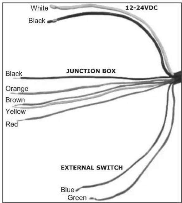
The cable from Antenna unit provides all power, data and control connections necessary for operation.
- The large Black and White leads are for power connections and connect directly to a 10.8 - 31.2 VDC power for MDS-1 and to a 10.8 - 41.6 VDC power for MDS-8/MDS-9/MDS-10-4/MDS-10-5.
- The five small wires (Black, Orange, Yellow, Brown, Orange) are connected to the Radar Junction Box.
- The two remaining small wires (Green and Blue) connect to the Radar On/Off switch.
NOTE
The "On/Off control switch" controls the main power to the Radar Antenna.
flowchart
graph TD
    A["White"] --> B["JUNCTION BOX"]
    C["Black"] --> B
    D["Blue"] --> E["EXTERNAL SWITCH"]
    F["Green"] --> E
    G["Orange"] --> E
    H["Brown"] --> E
    I["Yellow"] --> E
    J["Red"] --> E
    B --> K["12-24VDC"]
Figure 2.3 - Antenna Cable
2.4 CONNECTION PROCEDURE
NOTE
In the following procedure the small wires must be stripped and tinned, and then connected to the proper connections in the Radar Junction Box, and to pins on the On/Off control switch. If you are uncertain of your skill in completing these tasks, it is strongly advised to obtain the services of a qualified technician. It is essential to the operation and reliability of your Radar that these procedures are accomplished properly.
- Arrange the free end of the Antenna cable so that the wires will reach their intended points for connections.
- The two large wires must reach a power panel; the five leads in the braided fabric jacket must reach the Radar Junction Box and the two remaining leads must reach the desired location for the On/Off control switch.
- If the leads must go in different directions, first route the five leads in the fabric braid to the Junction Box. Then extend the shorter leads using the same size or larger size wire.
Please note that the power supply level at the Junction Box should be at least 12V since due the cable length the voltage at the Radar could drop below 10V.
The power supply cables should be of adequate diameter to feed the Radar, the Chart Plotter, the Junction Box and eventually any other instrument connected. The larger the diameter the better. A too small cable section could cause voltage drop over the cable with consequential overheating and danger of fire.
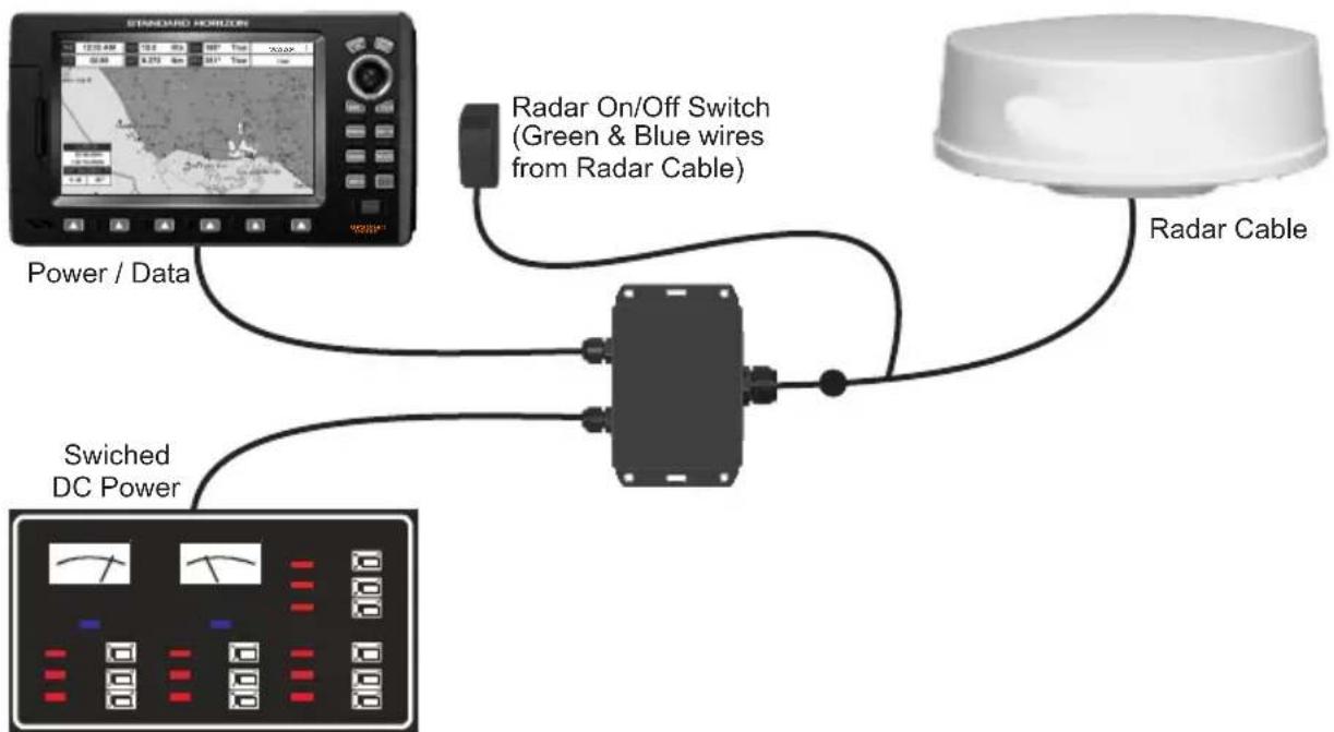
flowchart
graph TD
    A["STANDARD HORIZON"] --> B["Power / Data"]
    B --> C["Radar On/Off Switch (Green & Blue wires from Radar Cable)"]
    C --> D["Radar Cable"]
    D --> E["Switched DC Power"]
Figure 2.4 - Example of Connection Procedure for CP300
2.5 RADAR JUNCTION BOX CONNECTIONS
Referring to the diagram below, connect the color coded wires from the Radar cable to the designated place on Terminal strip A in Radar Junction Box as follows.
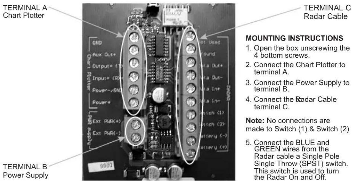
Figure 2.5 - Radar Junction Box
Terminal Strip A - Chart Plotter
This terminal strip is used to connect a compatible Standard Horizon GPS Chart Plotter to a Radar Antenna. Power – and Power+ connections are used to power the Standard Horizon Chart Plotter when connected.
Terminal Strip B - Power Supply
This terminal strip is used to connect the proper supply to power the Radar Antenna and
Standard Horizon Chart Plotter. Do not omit the in-line fuse unless a dedicated and fused terminal is available. If so, install a 5 Amp fuse.
Terminal Strip C - Radar Cable
This terminal strip is used to connect the Radar Antenna.
2.6 RADAR ANTENNA CONNECTIONS
2.6.0 DOME Connections
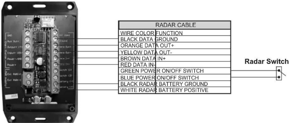
Figure 2.6.0 - DOME Connections
2.6.1 OPEN ARRAY Connections
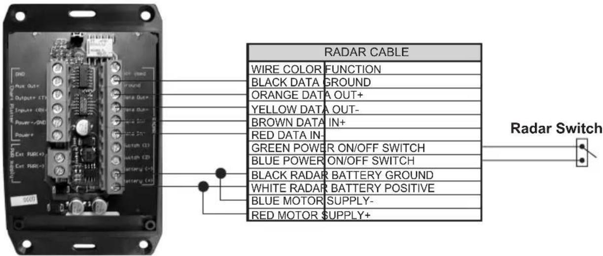
Figure 2.6.1 - OPEN ARRAY Connections
NOTE
When installing a Open Array Radar, it is important to connect:
a. Red (motor+) and White to B+ connection
b. Blue (motor -) and Black to B- connection.
2.7 CHART PLOTTER CONNECTIONS AND SET UP
The following instructions refer to Dome Antennas; refer to Open Array for connections.
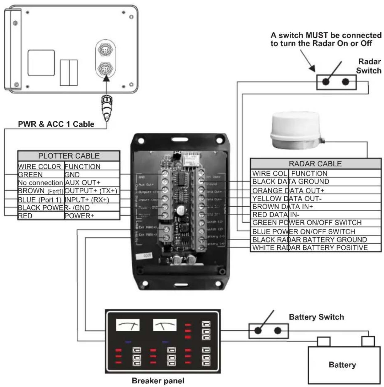
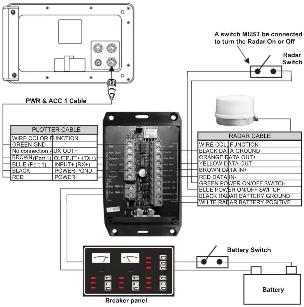
2.7.0 CP180 & CP180i Connections
flowchart
graph TD
    A["A switch MUST be connected to turn the Radar On or Off"] --> B["Radar Switch"]
    B --> C["PWR & ACC 1 Cable"]
    C --> D["PLOTTER CABLE"]
    D --> E["Breaker panel"]
    E --> F["Battery"]
    G["Radar Cable"] --> H["Switch"]
    H --> I["Black RADAR BATTERY GROUND"]
    H --> J["WHITE RADAR BATTERY POSITIVE"]
    K["Battery Switch"] --> L["Switch"]
    L --> M["Black RADAR BATTERY GROUND"]
    L --> N["GREEN POWER ON/OFF SWITCH"]
    L --> O["BLE POWER ON/OFF SWITCH"]
    P["WIRE COLOR FUNCTION"] --> Q["GREEN GND"]
    P --> R["No connection AUX OUT+"]
    P --> S["BROWN (Port1) OUTPUT+ (TX+)"]
    P --> T["BLUE (Port 1) INPUT+ (RX+)"]
    P --> U["BLACK POWER -/GND"]
    P --> V["RED POWER+"]
    W["AIR DATA OUT+"] --> X["Output+ CTN"]
    Y["ORANGE DATA OUT+"] --> Z["OUTPUT+ (TX+)"]
    AA["YELLOW DATA OUT-"] --> AB["INPUT+ (RX+)"]
    AC["RED DATA IN-"] --> AD["Switch CD3"]
    AE["GREEN POWER ON/OFF SWITCH"] --> AF["Switch CD5"]
    AG["BLE POWER ON/OFF SWITCH"] --> AH["Switch CD6"]
    AI["BLACK RADAR BATTERY POSITIVE"] --> AJ["Switch CD7"]
Figure 2.7.0 - CP180 & CP180i Connections
Port Setup
When an optional Radar Antenna is connected, Port 1 of the NMEA In/Out Communication Setup menu must be changed to RADAR as shown below for communications.
-
From the Chart page, press [MENU]. Move the ShuttlePoint knob to highlight SETUP MENU and press [ENT].
-
Move the ShuttlePoint knob to highlight ADVANCED SETUP and press [ENT].
- Move the ShuttlePoint knob to highlight IN/OUT CONNECTIONS and press [ENT].
- Move the ShuttlePoint knob to highlight PORT 1 INPUT and press [ENT].
- Move the ShuttlePoint knob up/down to select RADAR and press [ENT].
- Press [CLR] or move the ShuttlePoint knob to the left until the Chart page is shown.
2.7.1 CP300 & CP300i Connections
flowchart
graph TD
    A["A switch MUST be connected to turn the Radar On or Off"] --> B["Radar Switch"]
    B --> C["PWR & ACC 1 Cable"]
    C --> D["PLOTTER CABLE"]
    D --> E["WIRE COLOR FUNCTION"]
    D --> F["GREEN GND"]
    D --> G["No connection A UX OUT+"]
    D --> H["BROWN (Port 1) OUTPUT+ (TX+)"]
    D --> I["BLUE (Port 1) INPUT+ (RX+)"]
    D --> J["BLACK POWER-/GND"]
    D --> K["RED POWER+"]
    C --> L["RADAR CABLE"]
    L --> M["WIRE COL FUNCTION"]
    L --> N["BLACK DATA GROUND"]
    L --> O["ORANGE DATA OUT+"]
    L --> P["YELLOW DATA OUT-"]
    L --> Q["BROWN DATA IN+"]
    L --> R["RED DATA IN-"]
    L --> S["GREEN POWER ON/OFF SWITCH"]
    L --> T["BLUE POWER ON/OFF SWITCH"]
    L --> U["BLACK RADAR BATTERY GROUND"]
    L --> V["WHITE RADAR BATTERY POSITIVE"]
    C --> W["Breaker panel"]
    W --> X["Battery Switch"]
    X --> Y["Battery"]
Figure 2.7.1 - CP300 & CP300i Connections
Port Setup
When an optional Radar Antenna is connected, Port 1 of the NMEA In/Out Communication Setup menu must be changed to RADAR as shown below for communications.
- From the Chart page, press [MENU]. Move the ShuttlePoint knob to highlight SETUP MENU and press [ENT].
- Move the ShuttlePoint knob to highlight ADVANCED SETUP and press [ENT].
- Move the ShuttlePoint knob to highlight IN/OUT CONNECTIONS and press [ENT].
- Move the ShuttlePoint knob to highlight PORT 1 INPUT and press [ENT].
- Move the ShuttlePoint knob up/down to select RADAR and press [ENT].
- Press [CLR] or move the ShuttlePoint knob to the left until the Chart page is shown.
2.7.2 CPV350 Connections
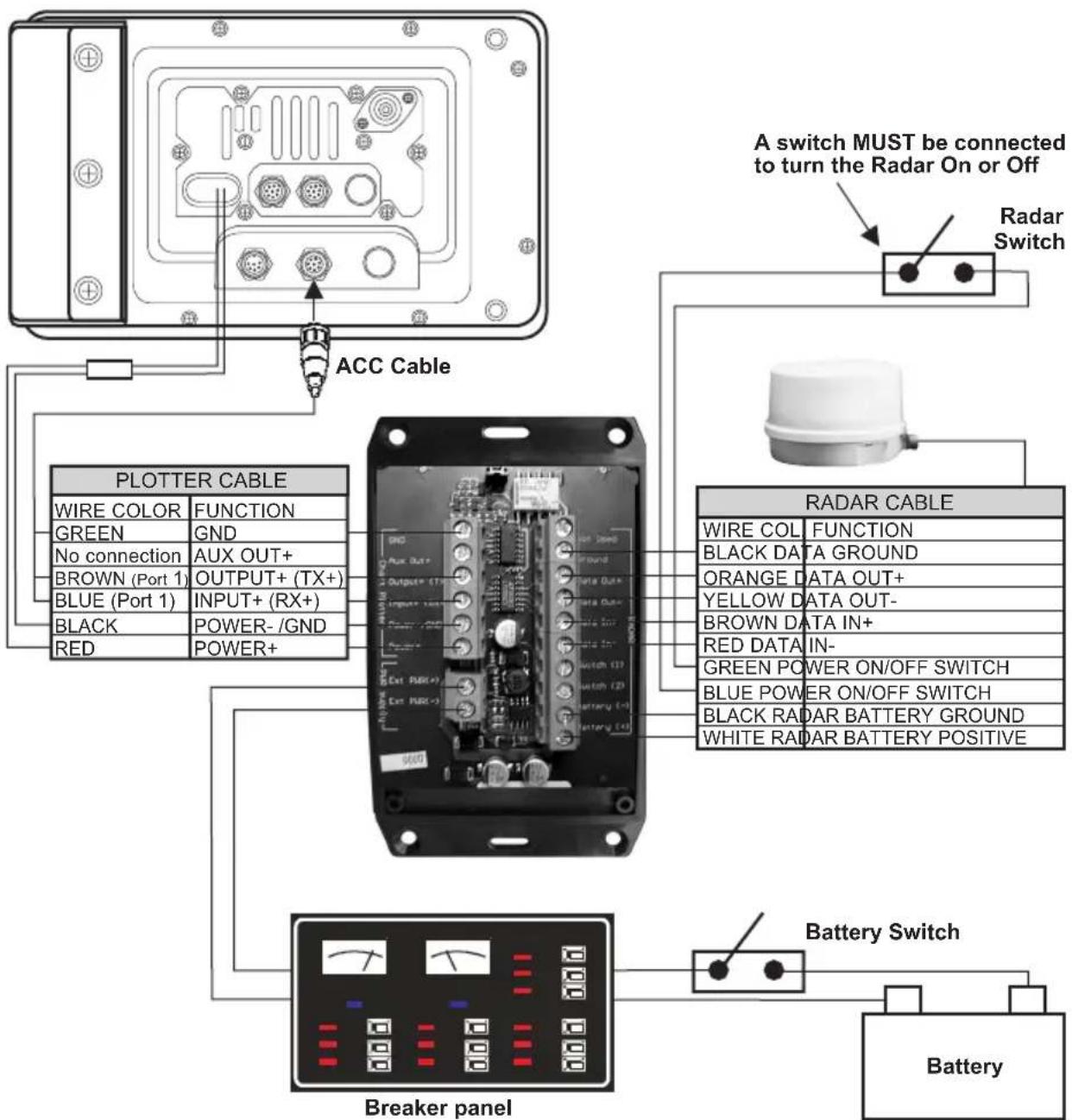
Figure 2.7.2 - CPV350 Connections
Port Setup
When an optional Radar Antenna is connected, Port 1 of the NMEA In/Out Communication Setup menu must be changed to RADAR as shown below for communications.
- From the Chart page, press [MENU]. Move the ShuttlePoint knob to highlight SETUP MENU and press [ENT].
- Move the ShuttlePoint knob to highlight ADVANCED SETUP and press [ENT].
- Move the ShuttlePoint knob to highlight IN/OUT CONNECTIONS and press [ENT].
- Move the ShuttlePoint knob to highlight PORT 1 INPUT and press [ENT].
- Move the ShuttlePoint knob up/down to select RADAR and press [ENT].
- Press [CLR] or move the ShuttlePoint knob to the left until the Chart page is shown.
2.7.3 CP500 Connections
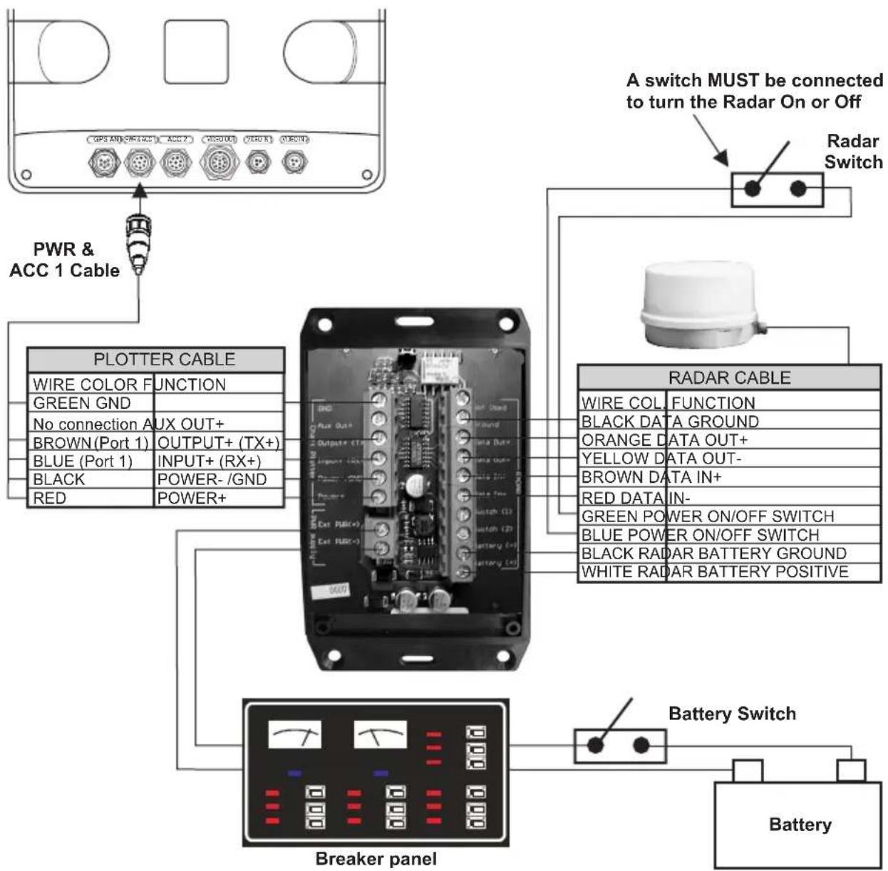
Figure 2.7.3 - CP500 Connections
Port Setup
When an optional Radar Antenna is connected, Port 1 of the NMEA In/Out Communication Setup menu must be changed to RADAR as shown below for communications.
-
From the Chart page, press [MENU]. Move the ShuttlePoint knob to highlight SETUP MENU and press [ENT].
-
Move the ShuttlePoint knob to highlight ADVANCED SETUP and press [ENT].
- Move the ShuttlePoint knob to highlight IN/OUT CONNECTIONS and press [ENT].
- Move the ShuttlePoint knob to highlight PORT 1 INPUT and press [ENT].
- Move the ShuttlePoint knob up/down to select RADAR and press [ENT].
- Press [CLR] or move the ShuttlePoint knob to the left until the Chart page is shown.
2.7.4 CPV550 Connections
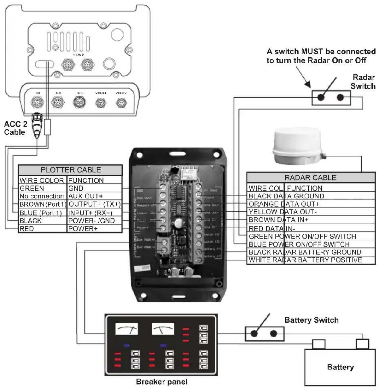
flowchart
graph TD
    A["1 RAM 2"] --> B["ACCC 2 Cable"]
    B --> C["PLOTTER CABLE"]
    C --> D["Breaker panel"]
    D --> E["Battery"]
    F["A switch MUST be connected to turn the Radar On or Off"] --> G["Radar Switch"]
    H["Radar Cable"] --> I["Breaker panel"]
    I --> J["Battery"]
    K["A switch MUST be connected to turn the Radar On or Off"] --> L["Radar Switch"]
    M["A switch MUST be connected to turn the Radar On or Off"] --> N["Radar Switch"]
Figure 2.7.4 - CPV550 Connections
Port Setup
When an optional Radar Antenna is connected, Port 1 of the NMEA In/Out Communication Setup menu must be changed to RADAR as shown below for communications.
- From the Chart page, press [MENU]. Move the ShuttlePoint knob to highlight SETUP MENU and press [ENT].
- Move the ShuttlePoint knob to highlight ADVANCED SETUP and press [ENT].
- Move the ShuttlePoint knob to highlight IN/OUT CONNECTIONS and press [ENT].
- Move the ShuttlePoint knob to highlight PORT 1 INPUT and press [ENT].
- Move the ShuttlePoint knob up/down to select RADAR and press [ENT].
- Press [CLR] or move the ShuttlePoint knob to the left until the Chart page is shown.
2.8 CHART PLOTTERS SOFTWARE UPDATE
The Software CARD is used to update the software in the Chart Plotter to be compatible with the Radar.
NOTE
Updating the software in the Chart Plotters with this Software CARD will erase all Marks and Routes that you have stored. Please read carefully the following paragraphs.
2.8.0 Backing up Marks and Routes
If you have created Marks and Routes you will need to either make note and manually re-enter them or purchase a optional User C-CARD.
Refer to the Chart Plotters's Owner's Manual for backing up the points.
2.8.1 Installing Software
Once you have backed up your User Points:
- Turn off the Chart Plotter and insert the Software CARD into any C-CARD slot on the Chart Plotter.
- Press and hold [PWR] until the Chart Plotter beeps, then release the key.
- Wait until the Start screen is shown, then remove the CARD.
- The software is now updated and the Chart Plotter is compatible with the Radar.
Figure 2.8.1 - Example of Start Up screen
3. TECHNICAL SPECIFICATIONS
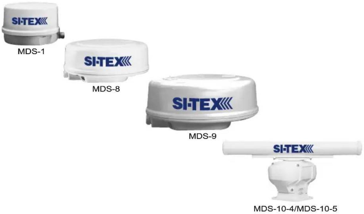
| Features | MDS-1 | MDS-8 | MDS-9 | MDS-10-4/MDS-10-5 |
 |  |  |  | |
| Antenna | 12.4 Inch-Dome | 20 Inch-Dome | 23.5 Inch-Dome | 47.25/59.1 Inch-Open Array |
| Peak Power Output 2KW 2KW 4KW 4KW | ||||
| Beam Width (degree) Horizontal | 7^ | 4.7^ | 4.0^ | 2.4^/1.7^ |
| Beam Width (degree) Vertical 25^ 25^ 25^ 25^ | ||||
| Rotation (RPM) 30 30 24 24 |
3.0 MDS-1
3.0.0 Antenna Unit
- Power supply : 10.8 to 31.2 VDC
- Power consumption : 30W or less
- Preheat times : 90 sec
- Aerial : Radome 0.9 Feet
- Peak power output : 2kW
- Transmitting frequency : 9445+/-30MHz
- Beam width (degree) Horizontal: 7^
- Vertical : 25°
- Sidelobes Within +/-10° : <=-20dB
- Rotation : 30rpm
- Pulse Length (μsec)/PRF (Hz) S : 0.1/2200
M, M1 : 0.3/1100
L, M2 : 0.8/550 - IF center frequency : 60MHz (Linear amplifier)
- IF bandwidth S : 6MHz
M, M1 : 6MHz
L, M2 : 3MHz - Noise figure : 10dB nominal
- Operating Temperature : -25°C \~ +55°C
• Operation in wind (relative) : 100 knots - Water Resistance : IPX6 (IEC60529)
- Preheat times output (by 5 sec step) : 85 sec to 5 sec
3.0.1 Dimensions and Mounting
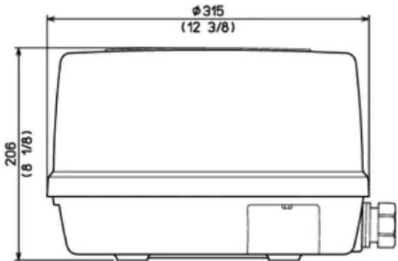
Figure 3.0.1 - Radar MDS-1 (I)
Weight: 4.5 kg (10 lb) without cable
Weight: 5.5 kg (12.5 lb) 10m cable included
Figure 3.0.1a - Radar MDS-1 (II)
3.1.0 Antenna Unit
• Power supply : 10.8 to 41.6 VDC
- Power consumption : 30W or less
- Preheat times : 90 sec
· Aerial : Radome 1.5 Feet
- Peak power output : 2kW
- Transmitting frequency : 9445+/-30MHz
- Beam width (degree) Horizontal : 4.7°
- Vertical : 25^
- Sidelobes Within +/-10° : <=-20dB
· Rotation : 30rpm
· Pulse Length ( μsec)/PRF (Hz) S : 0.1/2200
- M, M1 : 0.3/1100
· L, M2 : 0.8/550
· IF center frequency : 60MHz (Linear amplifier)
· IF bandwidth S : 6MHz
· M, M1 : 6MHz
· L, M2 : 3MHz
- Noise figure : 10dB nominal
· Operating Temperature : -25°C \~ +55°C
· Operation in wind (relative) : 100 knots
- Water Resistance : IPX6 (IEC60529)
- Preheat times output (by 5 sec step) : 85 sec to 5 sec
3.1.1 Dimensions and Mounting
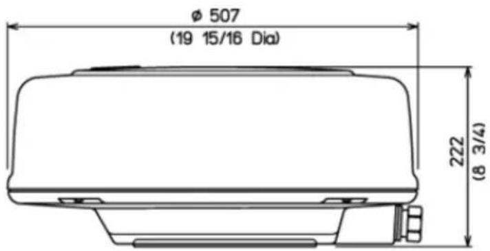
Figure 3.1.1 - Radar MDS-8 (I)
Weight: 8.1 kg (18.0 lb) 10m cable included
Weight: 68 kg (15.0 lb) without
Figure 3.1.1a - Radar MDS-8 (II)
3.2 MDS-9
3.2.0 Antenna Unit
- Power supply : 10.8 to 41.6 VDC
- Power consumption : 45W or less
- Preheat times : 120 sec
· Aerial : Radome 1.8 Feet - Peak power output : 4kW
- Transmitting frequency : 9410+/-30MHz
- Beam width (degree) Horizontal: 4.0^
Vertical : 25° - Sidelobes Within +/-10° : <=-20dB
· Rotation : 24rpm -
Pulse Length (μsec)/PRF (Hz) S : 0.1/2000
M, M1 : 0.25/2000
L, M2 : 0.5/1000
L, L1 : 1.0/500
· IF center frequency : 60MHz (Linear amplifier)
· IF bandwidth S : 6MHz
M, M1 : 6MHz
L, M2 : 3MHz
L, L1 : 3MHz -
Noise figure : 6.0dB or less
- Operating Temperature: -25^ +55^
• Operation in wind (relative) : 100 knots - Water Resistance : IPX6 (IEC60529)
- Preheat times output (by 5 sec step) : 115 sec to 5 sec
3.2.1 Dimensions and Mounting
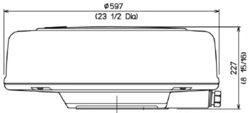
Figure 3.2.1 - Radar MDS-9 (I)
Weight: 9.7 kg (21.5lb) 10m cable included
Weight: 8.4 kg (19.0 lb) without cable
Figure 3.2.1a - Radar MDS-9 (II)
3.3.0 Antenna Unit
· Power supply : 10.8 to 41.6 VDC
- Power consumption : 80W or less
- Preheat times : 120 sec
· Aerial MDS-10-4 or MDS-10-5 : Open 4 or 5 Feet
- Peak power output : 4kW
- Transmitting frequency : 9410+/-30MHz
- Beam width (degree) Horizontal : 2.4° or 1.7°
Vertical : 25°
- Sidelobes Within +/-10° : <=-23dB
Outside +/-10° : <=-32dB
· Rotation : 24rpm
· Pulse Length ( μsec)/PRF (Hz) S : 0.06/4000
M, M1 : 0.15/2000
L, M2 : 0.4/1000
L, L1 : 1.0/500
· IF center frequency : 60MHz (Linear amplifier)
· IF bandwidth S : 20MHz
M, M1 : 20MHz
L, M2 : 5MHz
L, L1 : 5MHz
- Noise figure : 5.0dB or less
· Operating Temperature : -25°C \~ +55°C
· Operation in wind (relative) : 70 knots
· Water Resistance : IPX6 (IEC60529)
· Preheat times output (by 5 sec step) : 115 sec to 5 sec
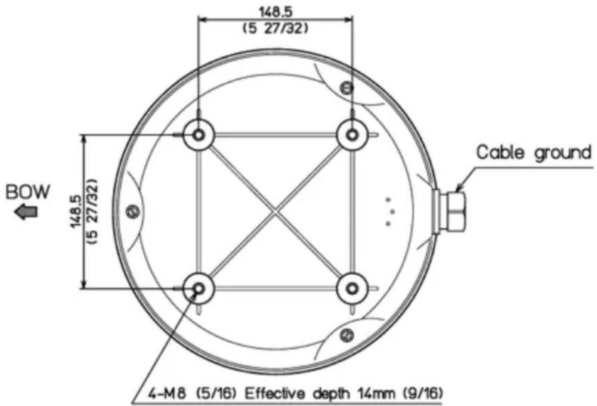
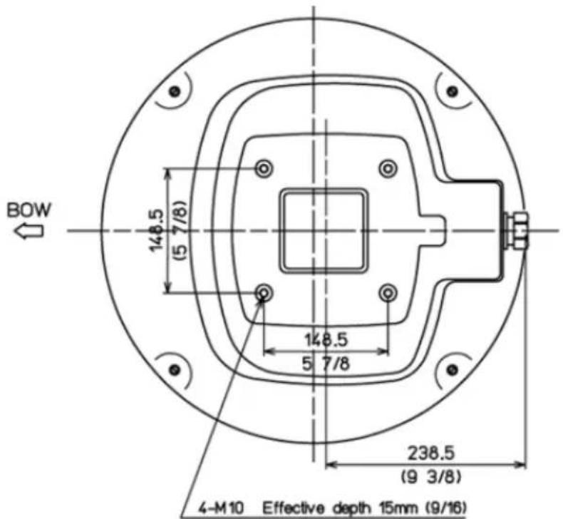
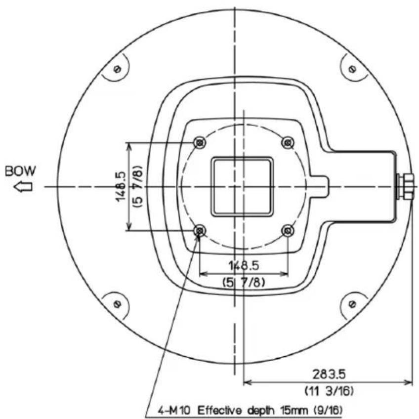
3.3.1 Dimensions and Mounting
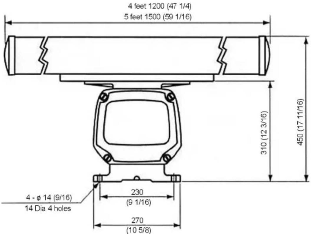
Figure 3.3.1 - Radar MDS-10-4/MDS-10-5 (II)
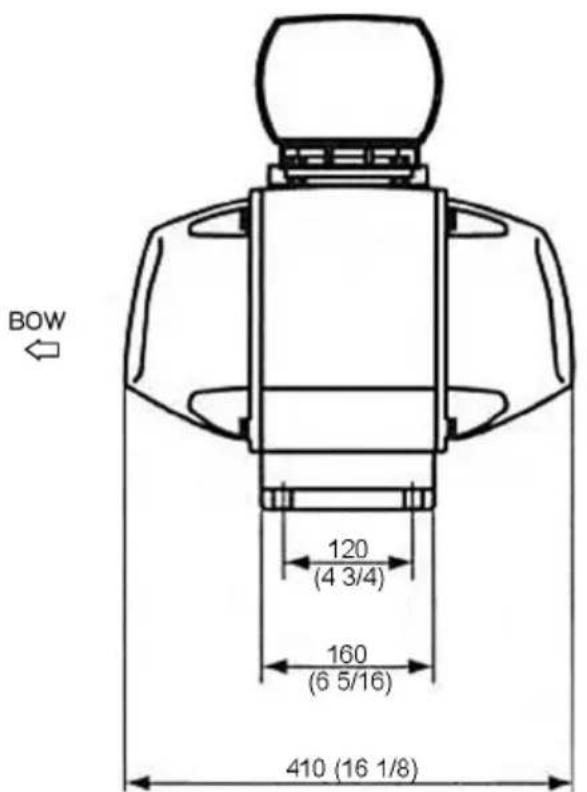
Weight: 21.2 Kg (47lb) 4 feet
Weight: 21.9 Kg (49lb) 5 feet
Figure 3.3.1a - Radar MDS-10-4/MDS-10-5 (III)
A.0 GENERAL
The word “radar” is an acronym for “RAdio Detecting And Ranging.” In very simple terms, this is how it works. A radio transmitter sends a quick microwave pulse, and then a receiver listens for that signal’s echo when it is bounced back from something in its path. The returning signal is processed by a computer to determine its relative distance, position and bearing. This information is graphically displayed on a screen for you to see. Other boats or ships, navigational markers, landmasses and such are referred to as targets.
By knowing how long it takes for a signal to return, the distance to a target can be determined. As the radar antenna scans through a 360-degree rotation, it can show where the target is relative to your position. By repeated scans, you can see which direction another vessel is moving.
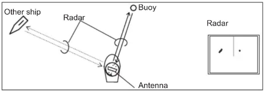
Figure A - Radar
A.0.0 Antenna
How radar will perform is largely determined by its antenna or scanner. Increasing the size of the antenna improves long-range performance and target discrimination, or the ability to distinguish two separate targets at a distance. The critical factors are the antenna's beam width and side lobe level. Typically, a radar antenna will radiate a tightly focused beam from the front of the array. The longer the antenna array is, the narrower the beam width will be. Additionally, it will also emit smaller amounts of energy to each side. The lower the side lobe level, the less the effect of a false echo.
A.0.1 Side Lobe
The beam in which the strongest radio signal is radiated from the antenna is called the “main lobe”. Those beams that are radiated in other directions are referred to as the “side lobes”. The side lobe level refers to the difference in level (signal strength) between the largest side lobe and the main lobe.
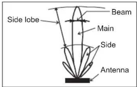
Figure A.0.1 - Antenna pattern
A.1 CHARACTERISTICS OF RADAR WAVE
Radio waves travel out from the antenna while bending slightly along the earth's surface. The amount they bend depends on atmospheric conditions. The sight distance of a radar generally is about 6% longer than the optical sight distance and is calculated using this equation: Radar sight distance (NM) = 2.22 ( height (m) + height (m))
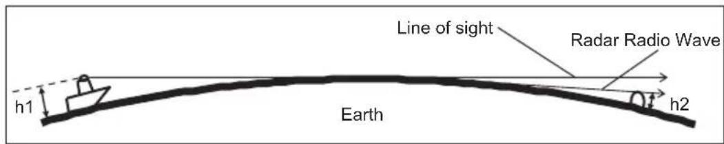
Figure A.1 - Radar wave
A.1.0 Targets difficult to display on screen
The intensity of the reflected radio signal from a target depends on the distance, height, and size of the target, as well as its material and shape, along with the radar's transmitter power output and antenna size. Targets made of fibreglass, wood, or other low-reflectance materials or those that have a small incident angle are difficult to display on a screen. Sandy beaches, and sandy or muddy shallows can be difficult to catch. Because there's not much to reflect a signal back to you, a coastline can actually be closer to your boat than it appears on the screen.
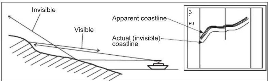
Figure A.1.0 - Targets difficult to display on screen
A.1.1 Shadow zones of radar
Radar waves propagate in a straight line. A high outcropping of land or a large ship will
create a shadow zone behind it and prevent you from seeing targets on the other side. More importantly, if a mast or some part of the boat's superstructure is in the path of the antenna's sweep, this will also create a shadow zone. No targets will be recognized behind it and it could create a dangerous situation.
A.1.2 False echoes
Sometimes radar will display targets on screen that do not exist in the real world. You should be aware of how and why this happens.
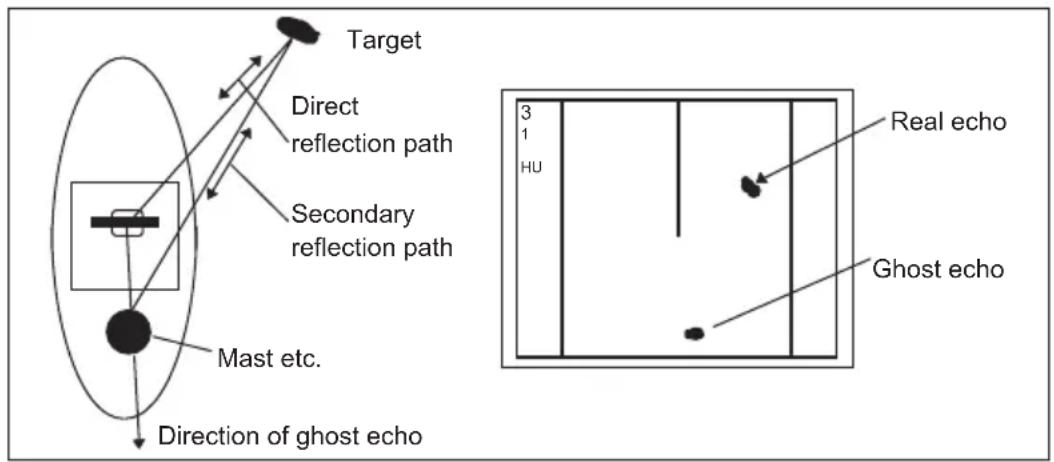
Ghost echoes
Sometimes one large object very near your boat will appear as two different targets on screen. One is the actual radar echo. The other is a ghost echo generated by a re-reflection of the original signal. It comes back to your own boat, bounces back to the target, and then is picked up by the antenna on the second bounce. The actual echo appears at the correct distance and bearing on the screen. The ghost echo appears somewhere behind your boat. This type of false echo is also generated by re-reflection of waves from bridges, break walls or building along shore.
flowchart
graph TD
    A["Target"] --> B["Direct reflection path"]
    B --> C["Secondary reflection path"]
    C --> D["Mast etc."]
    D --> E["Direction of ghost echo"]
    F["Real echo"] --> G["Ghost echo"]
    style A fill:#f9f,stroke:#333
    style B fill:#ccf,stroke:#333
    style C fill:#cfc,stroke:#333
    style D fill:#fcc,stroke:#333
    style E fill:#cff,stroke:#333
    style F fill:#ffc,stroke:#333
    style G fill:#cfc,stroke:#333
    style_H["Hu"] --> I["3"]
    I --> J["1"]
    I --> K["Real echo"]
Figure A.1.2 - Ghost Echoes
Multiple echoes
If there is a large vertical reflecting surface near your boat, as in the case when you pass alongside a large ship, radar signals are repeatedly bounced back and forth between your boat and the other object. Two to four images appear on the screen at equal intervals in the same bearing. This is called a multiple echo. The image appearing closest to you is the real echo. Multiple echoes will disappear as you move away from the reflecting object or its bearing changes.
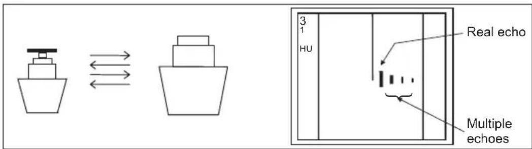
Figure A.1.2a - Multiple Echoes
False echoes caused by side lobe
An antenna's side lobe emissions are low power, and will not register distant targets. However, if there is a strong reflecting target near your boat, it sometimes may appear as a circular-arc false echo on the screen.
WARNING
When near large targets or land, your boat's mast may sometimes appear as circular-arc shaped false echo.
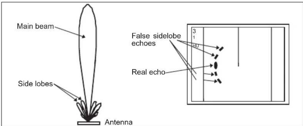
Figure A.1.2b - False Echoes caused by side lobe
Distant False echoes caused by duct phenomenon
The duct phenomenon sometimes occurs when meteorological conditions create a temperature inversion between layers of air. When this happens, radar waves propagate erratically and can reach a location considerably farther away from your boat than the radar's maximum distance range. What appears on screen is a false echo that looks to be nearer than the actual target. Since the true echo from the distant target is outside the measurement capabilities of the radar, its apparent distance will change when you change ranges, and you can conclude that it's a false echo.
Radar interference
If another boat's radar is operating on the same frequency as yours, it can create interference on your display. The interference usually appears as spiral or radial patterns. This radar has an interference rejection control to eliminate interference. Turn it on to reduce
or eliminate the interference.
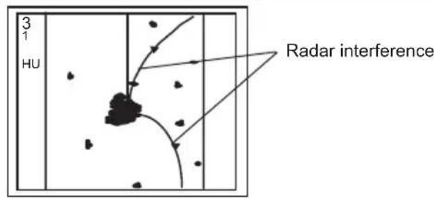
Figure A.1.2c - Radar interference
B.0 MORE INSTALLATION CONSIDERATIONS
B.0.0 Shifting from keel line
By shifting the scanner position from the keel line to the starboard side of the boat, it is possible to move shadow zones to the port side. This makes it possible to keep a clear view to the bow. The distance to be shifted can be calculated using the following equation:
$$ \mathrm{Ls} = 0. 4 \mathrm{R} + \mathrm{D} / 2 [ \mathrm{m} ] (\text { when } \mathrm{R} < 1 5 \mathrm{m}) $$
$$ \mathrm{Ls} = 0. 0 2 5 \mathrm{R} + \mathrm{D} / 2 [ \mathrm{m} ] (\text {when R > = 15m}) $$
where Ls = distance to be shifted from keel line
D = diameter of obstacle on keel line
R = distance from scanner to obstacle
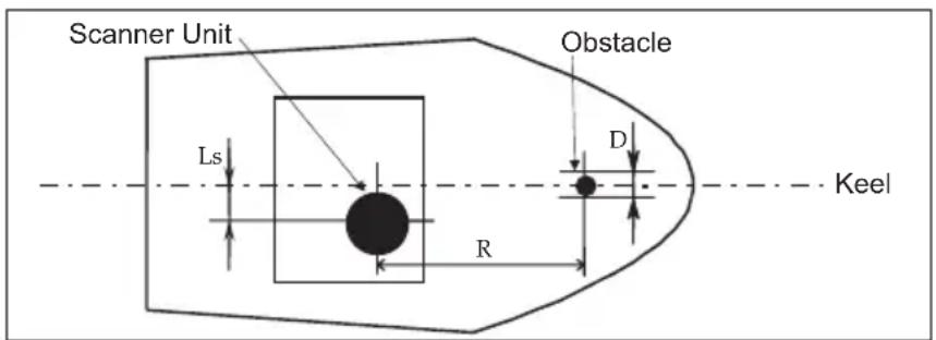
Figure B.0.0 - Shifting from keel line
B.0.1 Obtaining sufficient dip angle
Raise the scanner position so that there is a sufficient dip angle available between the line of sight from the scanner to the obstacle and the horizontal line. By raising the dip angle above 5^ , it is possible to prevent mid- and long-distance shadow zones. The radar cannot detect objects below the line of sight.
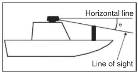
Figure B.0.1 - Obtaining sufficient dip angle
B.1 INSTALLING SCANNER UNIT
Use a mounting base such as the ones shown in Figure B.1, or you can install the scanner directly to a roof or other flat surface. Be certain you keep the water drain tube clear. It's located at the bottom of the scanner unit.
NOTE
If the mounting bracket or surface has a curvature of more than 2mm, use spacers with the mounting bolts to prevent stress on the scanner housing.
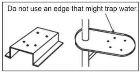
Figure B.1 - Installing scanner unit
A
Aerial 23, 25, 26, 28
Antenna 31
ANTENNA CONNECTIONS 15
Antenna Unit 23, 25, 26, 28
B
Backing up 21
Beam width 23, 25, 26, 28
C
cable from Antenna 12
CONNECTION PROCEDURE 13
CONVENTIONS 9
CP180 & CP180i 16
CP300 & CP300i 17
CP500 19
CPV350 18
CPV550 20
D
DATA CONNECTIONS 12
Dimensions 24, 25, 27, 29
E
ELECTRICAL CONNECTIONS 12
F
False echoes 33
G
Ghost echoes 33
|
INSTALLATION 11,37
Installing Software 21
J
JUNCTION BOX 14
K
keel line 37
L
legend 9
M
Magnetron 6
Marks 21
MDS-1 23
MDS-10-4/MDS-10-5 28
MDS-8 25
MDS-9 26
Microwave Radiation 5
Mounting 24, 25, 27, 29
Multiple echoes 33
N
Noise figure 23, 25, 27, 28
0
Operating Temperature 23, 25, 27, 28
Operation in wind 23, 25, 27, 28
P
PACKING LIST 10
Peak power output 23, 25, 26, 28
Port Setup 16, 17, 19, 20, 21
Power consumption 23, 25, 26, 28
Power supply 9, 23, 25, 26, 28
Preheat 23, 25, 27, 28
Preheat times 23, 25, 26, 28
Preheating 6
Product Support 10
Pulse Length 23, 25, 26, 28
R
Radar interference 34
RADAR WAVE 32
Replacement Parts 10
Rotation 23, 25, 26, 28
Routes 21
S
SAFETY PRECAUTIONS 5
SCANNER UNIT 38
Shadow zones 32
Sidelobe 23, 25, 26, 28, 31, 34
Software CARD 21
SOFTWARE UPDATE 21
SPECIFICATIONS 23
T
Targets 32
Transmitting frequency 23, 25, 26, 28
U
User C-CARD 21
W
Warning 5
Water Resistance 23, 25, 27, 28
WAVE 32
WHAT IS RADAR 31
PLEASE NOTE
The following "Limited Warranty" is for customers that have purchased products in the United States. For Limited Warranty details outside the United States, contact the dealer in your country.
STANDARD HORIZON LIMITED WARRANTY
STANDARD HORIZON (a division of Vertex Standard USA) warrants, to the original purchaser only, each new Marine Product ("Product") manufactured and/or supplied by STANDARD HORIZON against defects in materials and workmanship under normal use and service for a period of 3 years from the date of purchase.
In the event of a defect, malfunction or failure of the Product during the warranty period, Standard Horizon's liability for any breach of contract or any breach of express or implied warranties in connection with the sale of Products shall be limited solely to repair or replacement, at its option, of the Product or part(s) therein which, upon examination by STANDARD HORIZON, appear to be defective or not up to factory specifications. STANDARD HORIZON may, at its option, repair or replace parts or subassemblies with or reconditioned parts and subassemblies.
To receive warranty service, the purchaser must deliver the Product, transportation and Insurance prepaid, to STANDARD HORIZON (Marine Division of Vertex Standard) - Attention Factory Service - 10900 Walker Street - Cypress, CA 90630, include proof of purchase indicating model, serial number and date of purchase.
STANDARD HORIZON will not warrant installation, maintenance or service of the Products. In all instances, STANDARD HORIZON's liability for damages shall not exceed the purchase price of the defective Product. This warranty only extends to Products sold within the 50 States of the United States of America and the District of Columbia.
STANDARD HORIZON will pay all labour and replacement parts charges incurred in providing the warranty repair service except where purchaser abuse or other qualifying exceptions exist. The purchaser must pay any transportation expenses incurred in returning the Product to STANDARD HORIZON for service.
This limited warranty does not extend to any Product which has been subjected to misuse, neglect, accident, incorrect wiring by anyone other than STANDARD HORIZON, improper installation, or subjected to use in violation of instructions furnished by STANDARD HORIZON, nor does this warranty extend to Products on which the serial number has been removed, defaced, or changed. STANDARD HORIZON cannot be responsible in any way for ancillary equipment not furnished by STANDARD HORIZON which is attached to or used in connection with Products, or for the operation of the Product with any ancillary equipment, and all such equipment is expressly excluded from this warranty. STANDARD HORIZON disclaims liability for range, coverage, or operation of the Product and ancillary equipment as a whole under this warranty.
STANDARD HORIZON reserves the right to make changes or improvements in Products, during subsequent production, without incurring the obligation to install such changes or improvements on previously manufactured Products. The implied warranties which the law imposes on the sale of this Product are expressly LIMITED, in duration, to the time period specified above. STANDARD HORIZON shall not be liable under any circumstances for consequential damages resulting from the use and operation of this Product, or from the breach of this LIMITED WARRANTY, any implied warranties, or any contract with STANDARD HORIZON. IN CONNECTION WITH THE SALE OF ITS PRODUCTS, STANDARD HORIZON MAKES NO WARRANTIES, EXPRESS OR IMPLIED AS TO THE MERCHANTABILITY OR FITNESS FOR A PARTICULAR PURPOSE OR OTHERWISE, EXCEPT AS EXPRESSLY SET FORTH HEREIN.
Some states do not allow the exclusion or limitation of incidental or consequential damages, or limitation on how an implied warranty lasts, so the above limitation or exclusions may not apply. This warranty gives specific legal right, and there may be other right which may vary from state to state.