A5460KA - Padlocks Master Lock - Free user manual and instructions
Find the device manual for free A5460KA Master Lock in PDF.

User questions about A5460KA Master Lock
0 question about this device. Answer the ones you know or ask your own.
Ask a new question about this device
Download the instructions for your Padlocks in PDF format for free! Find your manual A5460KA - Master Lock and take your electronic device back in hand. On this page are published all the documents necessary for the use of your device. A5460KA by Master Lock.
USER MANUAL A5460KA Master Lock
natural_image
Gray padlock with engraved text 'AMERICAN 1023' on its body (no other readable text or symbols)
text_image
HARDECKY AMERICAN LOCK®
natural_image
Two metallic padlocks with 'AMERICAN LOCK®' branding, displayed side by side (no additional text or symbols visible)
text_image
AMERICAN LOCK 800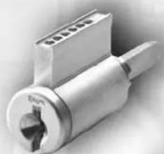
natural_image
Close-up of a metallic mechanical component with a central knob and threaded shaft (no visible text or symbols)
natural_image
Close-up of a metalliclic lock component with a handle and circular head detail (no visible text or symbols)
natural_image
Close-up of a metallic connector with threaded body and central knob (no visible text or symbols)
text_image
WARDEVED AMERICAN LOCK®
text_image
SERIES 2000 AMERICAN LOCK®2013
Commercial Security Products
SERVICE MANUAL
Table of Contents
Padlock Servicing Procedures
Series A700 2
Series A748 3
Series A780, A790 4
Series A1000, A5000, A6000 5
Series A5400, A6400 (Stainless Steel). 6
Series A1405 8
Series A2000 & A2010 9
Series A2500 10
Series A3100, A3200, A3500 (Interchangeable Core – IC). 11
Series A3600 and A3700 (Key-In-Knob - KIK) 12
Series A3800 13
Series A3900 14
Series A7000 (Tubular) 15
Series AH10 (Blade) 16
Series AL50 17
Weatherbuilt Covers....18
Service Parts
Actuators
American Lock Actuators....20
Actuators for Master Lock Cylinders....22
Drivers 23
Cylinders
Pin Tumbler 24
BumpStop™ Mechanism....25
Interchangeable Core 26
Door Hardware Multi-Cylinders 26
Edge™ Key Control Cylinders 27
Edge™ System Master Keying. 27
Rim, Mortise & KIK Cylinders 28
Door Hardware Component Parts. 29
Tubular....30
Disc Tumbler 31
Retainers & Trap Doors 32
Keys 33
Bitting Specifications 34
Lock Lubricants 34
Service Kits .... Back Cover
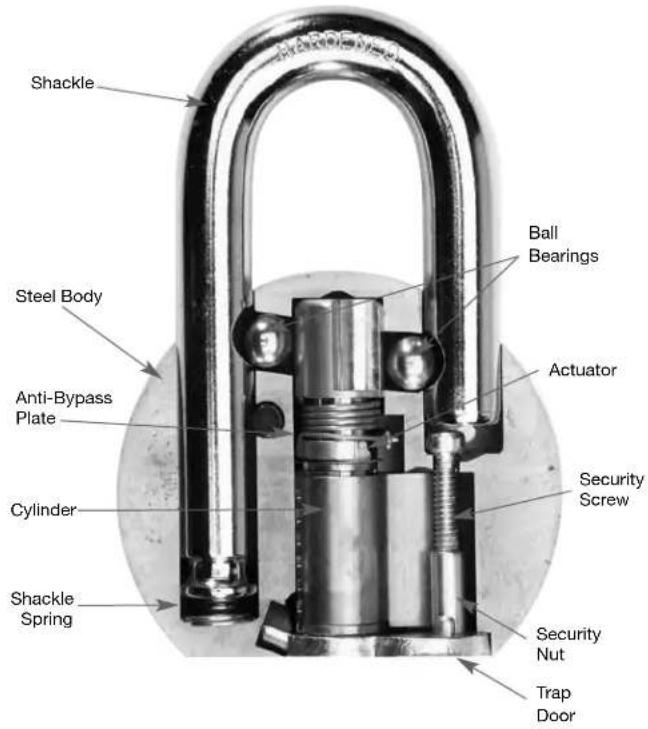
Disassembly
- Unlock shackle
- Use a Phillips screwdriver to remove security screw
- Remove security nut and trap door
- Remove cylinder and anti-bypass plate
- Place lock on flat surface and close shackle
- Actuator and ball bearings should fall out, if not, see page 20
- Remove shackle retaining screw, (APKG4765010)
- Remove shackle and spring
Assembly
- Insert shackle spring and shackle
- Insert and tighten shackle retaining screw
- Insert ball bearings
- Insert actuator as shown
- Check operation with follower tool
- Insert cylinder and rotate clockwise
- Insert trap door
- Insert security nut and screw
- Tighten security screw
- Check operation
text_image
SHAKLE Steel Body Anti-Bypass Plate Cylinder Shackle Spring Ball Bearings Actuator Security Screw Security Nut Trap Door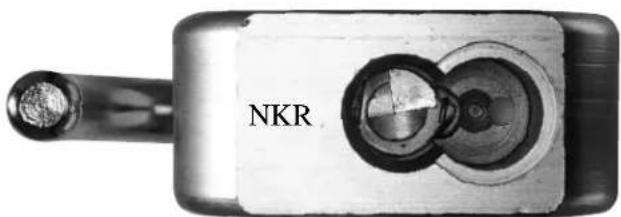
natural_image
Close-up of a metallic electronic device with two circular components and a central lens, labeled 'NKR' (no additional text or symbols visible)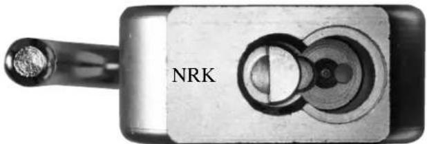
natural_image
Close-up of a metallic electronic device labeled 'NRK' with a circular button and connector (no additional text or symbols visible)| Model | Shackle | Shackle Spring | Actuator | Ball Bearings | |||
| Diameter Length | Part No. | NKR NRK | |||||
| A700, A700W0, A706 7/16" | 1-1/16" APKG158 | 2940 APKG16120 | 10 APKG2029010 | APKG2084090 APKG1807020 | |||
| A702, A702W0 (zinc) 7/16" | 1-1/16" APKG158 | 2950 APKG161201 | 10 APKG2029010 | APKG2084090 APKG1807020 | |||
| A701, A701W0, A707 7/16" | 2" APKG1582960 | APKG1612010 | APKG2029010 | APKG2084090 APKG1807020 | |||
| A703, A703W0 (zinc) 7/16" | 2" APKG1582970 | APKG1612010 | APKG2029010 | APKG2084090 APKG1807020 | |||
For Quantity Content and Ordering Information See the Price Book For Trap Door Part Numbers, See Page 32
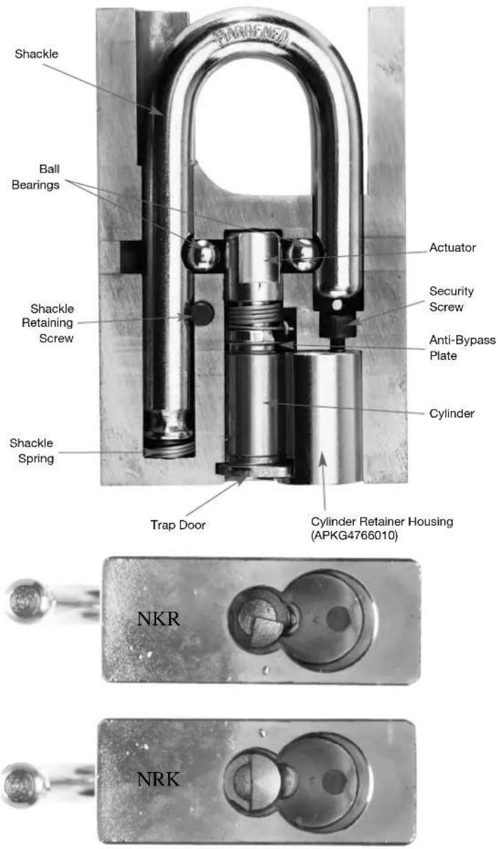
Disassembly
Disassembly
- Unlock shackle
- Use a 5/32" hex wrench to remove security screw
- Remove cylinder retaining housing
- Remove trap door, cylinder and anti-bypass plate
- Place lock on flat surface and close shackle
- Actuator and ball bearings should fall out, if not, see page 20
- Remove 3/32" hex shackle retaining screw
- Remove shackle and spring
Assembly
- Insert shackle spring and shackle
- Insert and tighten shackle retaining screw
- Insert ball bearings
- Insert actuator as shown
- Check operation with follower tool
- Insert cylinder and rotate clockwise
- Insert trap door
- Insert cylinder retainer housing
- Insert security screw
- Tighten security screw
- Check operation
| Model | Shackle | Shackle Spring | Actuator | Ball Bearings | |||
| Diameter Length | Part No. | NKR NRK | |||||
| A748 7/16" 1-1/16" | APKG1583290 | APKG1612010 | APKG1188300 | G0000274 APKG1 | 807020 | ||
For Quantity Content and Ordering Information See the Price Book For Trap Door Part Numbers, see page 32
Disassembly
- Unlock shackle
- Use a 5/32" hex wrench to remove security screw
- Relock shackle: remove key
- Remove cylinder retaining housing
- Remove trap door and cylinder
- Place lock on flat surface and close shackle
- Actuator and ball bearings should fall out, if not, see page 20
- Remove shackle 1/8" hex retaining screw
- Remove shackle
Assembly
- Insert shackle
- Insert and tighten shackle retaining screw
- Insert ball bearings
- Insert actuator as shown
- Check operation with follower tool
- Insert cylinder and rotate clockwise
- Insert trap door
- Insert cylinder retainer housing
- Insert security screw
- Unlock shackle
- Tighten security screw
- Check operation
For cylinder retainer housing use part number (A3031010).

text_image
SHARLENEO Shackle Ball Bearings Actuator Shackle Retaining Screw Security Screw Cylinder Trap Door Cylinder Retainer Housing (APKG4766010)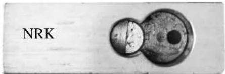
text_image
NRK| Model | Shackle | Shackle Screw | Actuator | Ball Bearings | |||
| Diameter Length | Part No. | NKR NRK | |||||
| A780 7/16" 1-1/4" | APKG0000273 | APKG4765010 N/A | APKG0000274 | APKG1807020 | |||
| A790 1/2" 1-1/2" | APKG1583280 | APKG4765010 N/A | APKG0000275 | APKG1809010 | |||
For Quantity Content and Ordering Information See the Price Book For Trap Door Part Numbers, see page 32
American Lock Series A1000, A5000 & A6000
Disassembly
- Unlock shackle
- Use a Phillips screwdriver to remove security screw
- Remove security nut and trap door
- Remove cylinder and anti-bypass plate
- Place lock on flat surface and close shackle
- Actuator and ball bearings should fall out, if not, see page 20
- Remove shackle and spring
Assembly
- Insert shackle spring and shackle
- Insert ball bearings
- Insert actuator as shown
- Check operation with follower tool
- Insert cylinder and rotate clockwise
- Insert trap door
- Insert security nut and screw
- Tighten security screw
- Check operation
(see page 7 for A1000, A5000 and A6000 Specifications Chart)
text_image
SHARLENE Shackle Ball Bearings Actuator Security Screw Anti-Bypass Plate Shackle Spring Cylinder Trap Door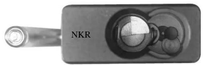
natural_image
Close-up of a black electronic device with a metallic knob and circular ports, labeled 'NKR' (no other text or symbols visible)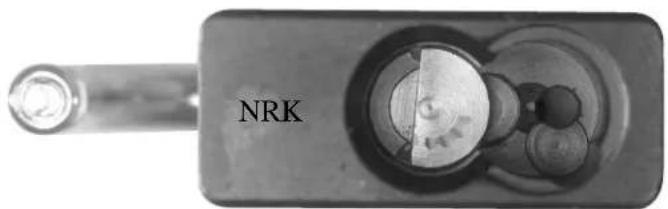
natural_image
Close-up of a mechanical component labeled 'NRK' with internal circular features (no readable text beyond label)American Lock Stainless Steel Series A5400 & A6400
Disassembly
- Unlock shackle
- Use a Phillips screwdriver to remove security screw
- Remove security nut and trap door
- Remove cylinder and anti-bypass plate
- Place lock on flat surface and close shackle
- Actuator and ball bearings should fall out, if not, see page 20
- Remove shackle and spring
Assembly
- Insert shackle spring and shackle
- Insert ball bearings
- Insert actuator as shown
- Check operation with follower tool
- Insert cylinder and rotate clockwise
- Insert trap door
- Insert security nut and screw
- Tighten security screw
- Check operation
(see page 7 for A5400 & A6400 Specifications Chart)
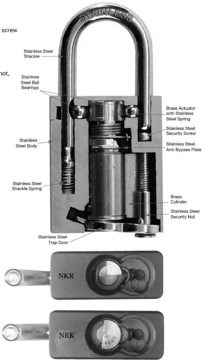
text_image
screw Stainless Steel Shackle Stainless Steel Ball Bearings Stainless Steel Body Stainless Steel Shackle Spring Stainless Steel Trap Door Brass Actuator with Stainless Steel Spring Stainless Steel Security Screw Stainless Steel Anti-Bypass Plate Brass Cylinder Stainless Steel Security Nut NKR NRKAmerican Lock Series A1000, A5000 & A6000 (Continued)
| MODEL | SHACKLE DIAMETER | LENGTH | PART NO. | SHACKLE SPRING | ACTUATOR | BALL BEARINGSNK | |
| A1105,A1105WO,A1165 1/4" 1" APKG1582980 APKG1613010 APKG1188270 APKG2081160 APKG1806010 | |||||||
| A1106,A1106WO,A1166 1/4" 1-1/2" APKG1583180 APKG1613010 APKG1188270 APKG2081160 APKG1806010 | |||||||
| A1107,A1107WO,A1167 1/4" 3" APKG1583210 APKG1613010 APKG1188270 APKG2081160 APKG1806010 | |||||||
| A1205,A1205WO,A1265 5/16" 1-1/8" APKG1582240 APKG1606010 APKG1188270 APKG2081160 APKG1806010 | |||||||
| A1205B,A1205BWO,A1265B | 5/16" | 3/4" | APKG1584030 | APKG1606010 | APKG1188270 | APKG2081160 | APKG1806010 |
| A1205SS,A1205SSWO,A1265SS | 5/16" | 1-1/8" | APKG0065435 | APKG0210031 | APKG1188270 | APKG2081160 | APKG1806010 |
| A1206,A1206WO,A1266 | 5/16" | 2" | APKG1582290 | APKG1606010 | APKG1188270 | APKG2081160 | APKG1806010 |
| A1206B,A1206BWO,A1266 | 5/16" | 2" | APKG0056794 | APKG1606010 | APKG1188270 | APKG2081160 | APKG1806010 |
| A1206SS,A1206SSWO,A1266SS | 5/16" | 2" | APKG0065436 | APKG0210031 | APKG1188270 | APKG2081160 | APKG1806010 |
| A1207,A1207WO,A1267 | 5/16" | 3" | APKG1582310 | APKG1606010 | APKG1188270 | APKG2081160 | APKG1806010 |
| A1207SS,A1207SSWO,A1267SS | 5/16" | 3" | APKG0065437 | APKG0210031 | APKG1188270 | APKG2081160 | APKG1806010 |
| A1209,A1209WO,A1269 | 5/16" | 5" | APKG0000954 | APKG1606010 | APKG1188270 | APKG2081160 | APKG1806010 |
| A1209SS,A1209SSWO,A1269SS | 5/16" | 5" | APKG0065438 | APKG0210031 | APKG1188270 | APKG2081160 | APKG1806010 |
| A1305,A1305WO,A1365 3/8" 1-1/8" APKG1581550 APKG1611010 APKG1188270 APKG2081160 APKG1806010 | |||||||
| A1305B,A1305BWO,A1365B | 3/8" | 1-1/8" | APKG0056760 | APKG1611010 | APKG1188270 | APKG2081160 | APKG1806010 |
| A1305SS,A1305SSWO,A1365SS | 3/8" | 1-1/8" | APKG0065432 | APKG0500023 | APKG1188270 | APKG2081160 | APKG1806010 |
| A1306,A1306WO,A1366 3/8" 2" APKG1581570 APKG1611010 APKG1188270 APKG2081160 APKG1806010 | |||||||
| A1306SS,A1306SSWO,A1366SS | 3/8" | 2" | APKG0065433 | APKG0500023 | APKG1188270 | APKG2081160 | APKG1806010 |
| A1307,A1307WO,A1367 3/8" 3" APKG1581590 APKG1611010 APKG1188270 APKG2081160 APKG1806010 | |||||||
| A1307SS,A1307SSWO,A1367SS | 3/8" | 3" | APKG0065434 | APKG0500023 | APKG1188270 | APKG2081160 | APKG1806010 |
| A5100,A5100WO,A6100 1/4" 1" APKG1582980 APKG1613010 APKG1188270 APKG2081160 APKG1806010 | |||||||
| A5101,A5101WO,A6101 1/4" 1-1/2" APKG1583180 APKG1613010 APKG1188270 APKG2081160 APKG1806010 | |||||||
| A5102,A5102WO,A6102 1/4" 3" APKG1583210 APKG1613010 APKG1188270 APKG2081160 APKG1806010 | |||||||
| A5200,A5200WO,A6200 5/16" 1-1/8" APKG1582240 APKG1606010 APKG1188270 APKG2081160 APKG1806010 | |||||||
| A5200SS,A5200SSWO,A6200SS | 5/16" | 1-1/8" | APKG0065435 | APKG0210031 | APKG1188270 | APKG2081160 | APKG1806010 |
| A5201,A5201WO,A6201 | 5/16" | 2" | APKG1582290 | APKG1606010 | APKG1188270 | APKG2081160 | APKG1806010 |
| A5201SS,A5201SSWO,A6201SS | 5/16" | 2" | APKG0065436 | APKG0210031 | APKG1188270 | APKG2081160 | APKG1806010 |
| A5202,A5202WO,A6202 | 5/16" | 3" | APKG1582310 | APKG1606010 | APKG1188270 | APKG2081160 | APKG1806010 |
| A5202SS,A5202SSWO,A6202SS | 5/16" | 3" | APKG0065437 | APKG0210031 | APKG1188270 | APKG2081160 | APKG1806010 |
| A5205,A5205WO,A6205 | 5/16" | 5" | APKG0000954 | APKG1606010 | APKG1188270 | APKG2081160 | APKG1806010 |
| A5205SS,A5205SSWO,A6205SS | 5/16" | 5" | APKG0065438 | APKG0210031 | APKG1188270 | APKG2081160 | APKG1806010 |
| A5260,A5260WO,A6260 3/8" 1-1/8" APKG1581550 APKG1611010 APKG1188270 APKG2081160 APKG1806010 | |||||||
| A5260SS,A5260SSWO,A6260SS | 3/8" | 1-1/8" | APKG0065432 | APKG0500023 | APKG1188270 | APKG2081160 | APKG1806010 |
| A5261,A5261WO,A6261 3/8" 2" APKG1581570 APKG1611010 APKG1188270 APKG2081160 APKG1806010 | |||||||
| A5261SS,A5261SSWO,A6261SS | 3/8" | 2" | APKG0065433 | APKG0500023 | APKG1188270 | APKG2081160 | APKG1806010 |
| A5262,A5262WO,A6262 3/8" 3" APKG1581590 APKG1611010 APKG1188270 APKG2081160 APKG1806010 | |||||||
| A5262SS,A5262SSWO,A6262SS | 3/8" | 3" | APKG0065434 | APKG0500023 | APKG1188270 | APKG2081160 | APKG1806010 |
| A5300,A5300WO,A6300 5/16" 1-1/8" APKG1582240 APKG1611010 APKG1188270 APKG2081160 APKG1806010 | |||||||
| A5360,A5360WO,A6360 3/8" 1-1/8" APKG1581550 APKG1611010 APKG1188270 APKG2081160 APKG1806010 | |||||||
| A5530,A5530WO,A6530 1/4" 1" APKG1582980 APKG1613010 APKG1188270 APKG2081160 APKG1806010 | |||||||
| A5530B,A5530BWO,A6530B | 1/4" | 1" | APKG1583240 | APKG1613010 | APKG1188270 | APKG2081160 | APKG1806010 |
| A5530,A5530WO,A6531 1/4" 1-1/2" APKG1583180 APKG1613010 APKG1188270 APKG2081160 APKG1806010 | |||||||
| A5530,A5530WO,A6532 1/4" 3" APKG1583210 APKG1613010 APKG1188270 APKG2081160 APKG1806010 | |||||||
| A5560,A5560WO,A6560 5/16" 1-1/8" APKG1582240 APKG1606010 APKG1188270 APKG2081160 APKG1806010 | |||||||
| A5560B,A5560BWO,A6560B | 5/16" | 3/4" | APKG0056792 | APKG1606010 | APKG1188270 | APKG2081160 | APKG1806010 |
| A5560SS,A5560SSWO,A6560SS | 5/16" | 1-1/8" | APKG0065435 | APKG0210031 | APKG1188270 | APKG2081160 | APKG1806010 |
| A5561,A5561WO,A6561 | 5/16" | 2" | APKG1582290 | APKG1606010 | APKG1188270 | APKG2081160 | APKG1806010 |
| A5561B,A5561BWO,A6561B | 5/16" | 2" | APKG0056794 | APKG1606010 | APKG1188270 | APKG2081160 | APKG1806010 |
| A5561SS,A5561SSWO,A6561SS | 5/16" | 2" | APKG0065436 | APKH0210031 | APKG1188270 | APKG2081160 | APKG1806010 |
| A5562,A5562WO,A6562 | 5/16" | 3" | APKG1582310 | APKG1606010 | APKG1188270 | APKG2081160 | APKG1806010 |
| A5562SS,A5562SSWO,A6562SS | 5/16" | 3" | APKG0065437 | APKG0210031 | APKG1188270 | APKG2081160 | APKG1806010 |
| A5565,A5565WO,A6565 | 5/16" | 5" | APKG000954 | APKG1606010 | APKG1188270 | APKG2081160 | APKG1806010 |
| A5565SS,A5565SSWO,A6565SS | 5/16" | 5" | APKG0065438 | APKG0210031 | APKG1188270 | APKG2081160 | APKG1806010 |
| A5570,A5570WO,A6570 3/8" 1-1/8" APKG1581550 APKG1606010 APKG1188270 APKG2081160 APKG1806010 | |||||||
| A5570B,A5570BWO,A6570B | 3/8" | 1-1/8" | APKG0056760 | APKG1606010 | APKG1188270 | APKG2081160 | APKG1806010 |
| A5570SS,A5570SSWO,A6570SS | 3/8" | 1-1/8" | APKG0065432 | APKG0500023 | APKG1188270 | APKG2081160 | APKG1806010 |
| A5571,A5571WO,A6571 3/8" 2" APKG1581570 APKG1606010 APKG1188270 APKG2081160 APKG1806010 | |||||||
| A5571SS,A5571SSWO,A6571SS | 3/8" | 2" | APKG0065433 | APKG0500023 | APKG1188270 | APKG2081160 | APKG1806010 |
| A5572,A5572WO,A6572 3/8" 3" APKG1581590 APKG1606010 APKG1188270 APKG2081160 APKG1806010 | |||||||
| A5572SS,A5572SSWO,A6572SS | 3/8" | 3" | APKG0065434 | APKG0500023 | APKG1188270 | APKG2081160 | APKG1806010 |
| A5400,A5400WO,A6400 5/16" 1-1/8" APKG0110032 APKG1606010 APKG1188270 APKG2081160 APKG1806010 | |||||||
| A5401,A5401WO,A6401 | 5/16" | 2" | APKG0110033 | APKG1606010 | APKG1188270 | APKG2081160 | APKG1806010 |
| A5460,A5460WO,A6460 3/8" 1-1/8" APKG0110029 APKG1611010 APKG1188270 APKG2081160 APKG1806010 | |||||||
| A5461,A5461WO,A6461 3/8" 2" APKG0110030 APKG1611010 APKG1188270 APKG2081160 APKG1806010 | |||||||
For Quantity Content and Ordering Information, See the Price Book
For Trap Door Part Numbers, see page 32
R NRK
American Lock Series A1405 (for Yale LFIC 1220)
Disassembly
- Unlock shackle
- Use control key to remove LFIC
- Remove driver
- Place lock on flat surface and close shackle
- Actuator and ball bearings should fall out, if not, see page 20
- Remove shackle and spring
Assembly
- Insert shackle spring and shackle
- Insert ball bearings
- Insert actuator as shown
- Check operation with follower tool
- Insert driver
- Insert LFIC with control key
- Check operation
text_image
Shackle Ball Bearings Actuator Shackle Spring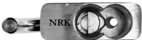
natural_image
Close-up of a metallic mechanical component with a circular end and central hole, labeled 'NRK' (no other text or symbols visible)| Model | Shackle | Shackle Spring | Actuator | Ball Bearings | |||
| Diameter Length | Part No. | NKR | NRK | ||||
| A1405 5/16" 1-1/8" | APKG1582240 | APKG1606010 | APKG1188270 | APKG2081160 | APKG1806010 | ||
| A1406 5/16" 2" | APKG1582290 | APKG1606010 | APKG1188270 | APKG2081160 | APKG1806010 | ||
| A1407 5/16" 3" | APKG1582310 | APKG1606010 | APKG1188270 | APKG2081160 | APKG1806010 | ||
| A1409 5/16" 5" | APKG0000954 | APKG1606010 | APKG1188270 | APKG2081160 | APKG1806010 | ||
For Quantity Content and Ordering Information, See the Price Book
text_image
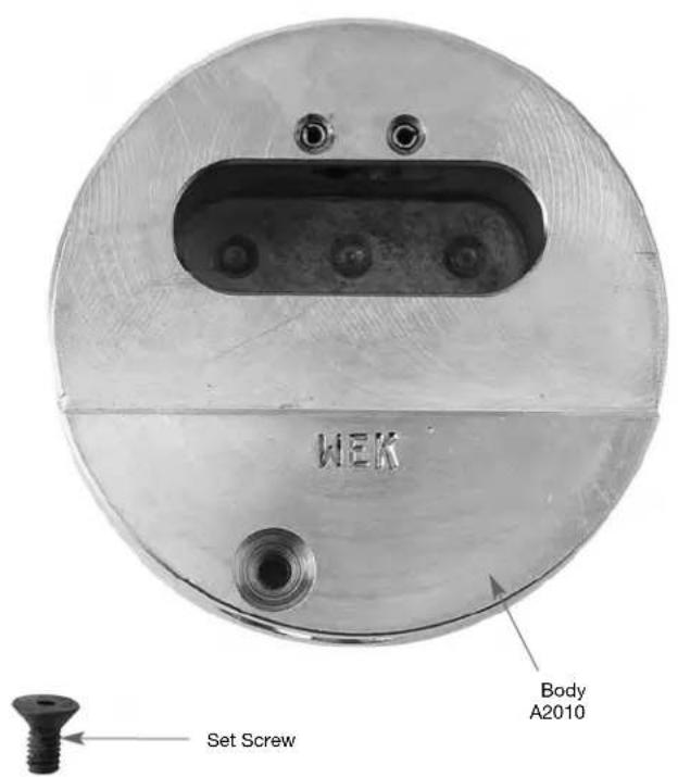
WEK Body A2010 Set Screw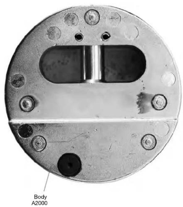
text_image
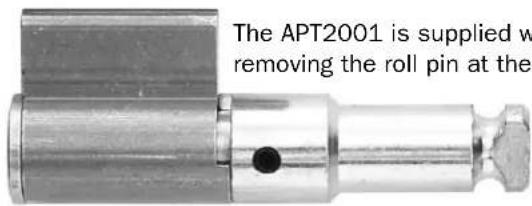
Body A2000Disassembly
- Remove 3/32" hex retaining screw
- Remove cylinder assembly
- Remove roll pin
- Rekey as required
Assembly
- Insert roll pin
- Insert cylinder assembly and lock into place
- Replace retaining screw
| Part number Description | |
| APT2001 6 pin cylinder and shackle assembly | |
| APT2001U Uncombinated 6 pin cylinder and shackle assembly | |
| APKG0000220 Retaining screw | |
| APKG0000431 A2000 and A2000WO cylinder housing | |
| APKG3023010 A2010 and A2010WO cylinder housing |
text_image
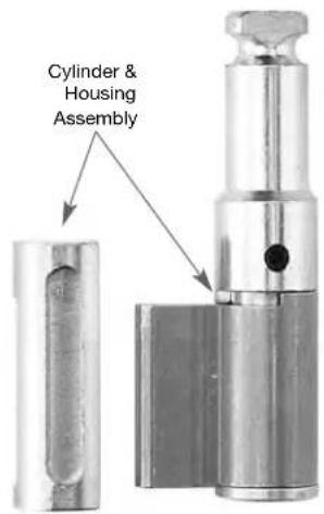
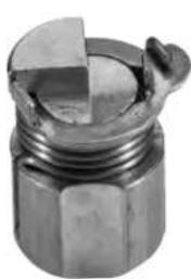
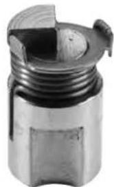
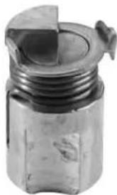
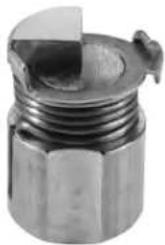
Cylinder & Housing AssemblyDisassembly
- Remove 3/32" hex cover plate screws and cover plate
- Remove lockbolt spring
- Remove cam
- Remove cylinder assembly and sleeve
- Remove lockbolt
- Remove shackle pin and spring
Assembly
- Insert shackle pin and spring
- Insert lockbolt
- Insert cylinder assembly and sleeve
- Insert cam
- Insert lockbolt spring
- Replace cover plate
- Replace and tighten cover plate screws
text_image
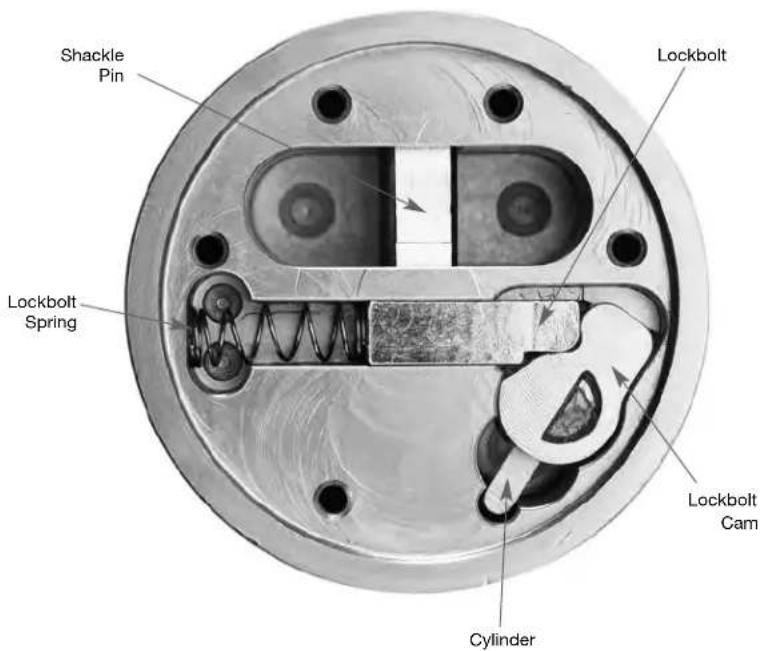
Shackle Pin Lockbolt Lockbolt Spring Lockbolt Cam Cylinder| Part number Description | |
| APTC12S 5 pin cylinder | assembly with stainless steel pins |
| APTC14S 6 pin cylinder | assembly with stainless steel pins |
| APKG0001583 Lockbolt | cam |
| APKG0001584 Lockbolt | |
| APKG0001585 Shackle | pin |
| APKG0001586 Hardened cylinder cover | |
| APKG0001587 Cylinder | sleeve |
| APKG0001588 Cover plate | |
| APKG0001589 Lockbolt | spring |
| APKG0001590 Shackle | spring |
| APKG0001591 Cover plate screws | |
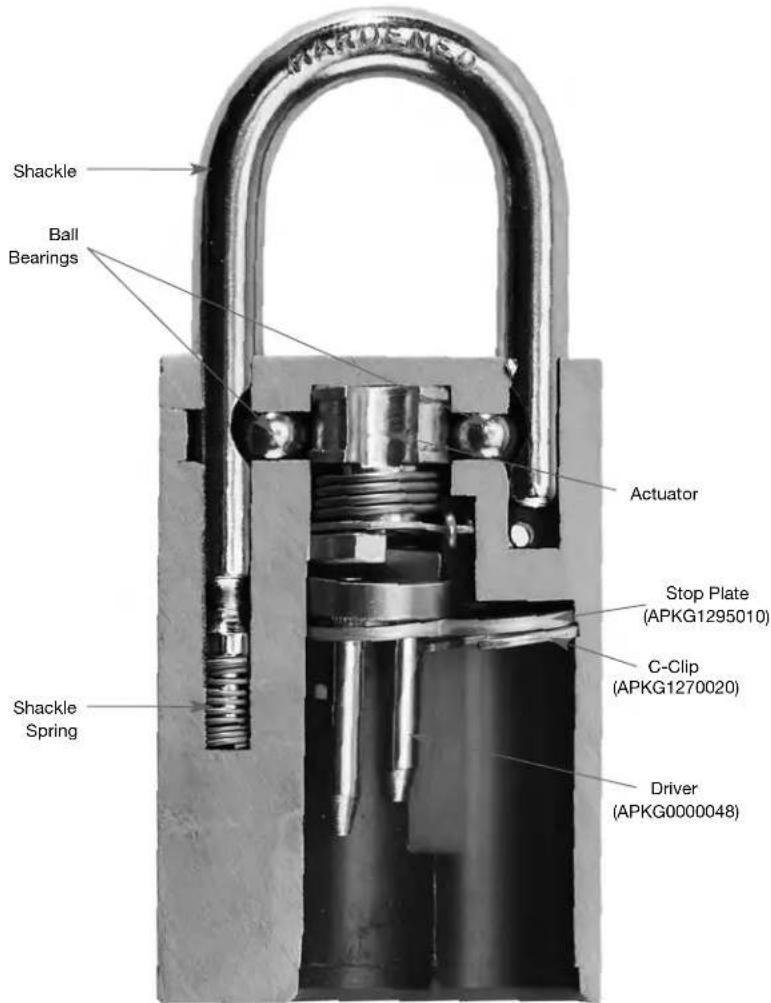
Disassembly
- Unlock shackle
- Use control key to remove SFIC
- Remove C clip and stop plate
- Remove driver
- Place lock on flat surface and close shackle
- Actuator and ball bearings should fall out, if not, see page 20
- Remove shackle and spring
Assembly
- Insert shackle spring and shackle
- Insert ball bearings
- Insert actuator as shown
- Insert driver, stop plate, (with 'T' up), and C clip
- Check operation with follower tool
- Insert SFIC with control key
- Check operation
text_image
SHAKLE Ball Bearings Actuator Stop Plate (APKG1295010) C-Clip (APKG1270020) Shackle Spring Driver (APKG0000048)| Model | Shackle | Shackle Spring | Actuator | Ball Bearings | |||
| Diameter | Length | Part No. | NKR | NRK | |||
| 3105 1/4" 1" APKG1582980 APKG1613010 APKG1188270 APKG2081160APKG1806010 | |||||||
| 3106 1/4" 1-1/2" APKG1583180 APKG1613010 APKG1188270 APKG2081160APKG1806010 | |||||||
| 3107 1/4" 3" APKG1583210 APKG1613010 APKG1188270 APKG2081160APKG1806010 | |||||||
| 3260, 3570 3/8" 1-1/8" APKG1581550 APKG1601010 APKG1188270 APKG2081160APKG1806010 | |||||||
| 3261, 3571 3/8" 2" APKG1581570 APKG1601010 APKG1188270 APKG2081160APKG1806010 | |||||||
| 3262, 3572 3/8" 3" APKG1581590 APKG1601010 APKG1188270 APKG2081160APKG1806010 | |||||||
| 3200, 3560 | 5/16" | 1-1/8" | APKG1582240 | APKG1606010 | APKG1188270 | APKG2081160 | APKG1806010 |
| 3201, 3561 | 5/16" | 2" | APKG1582290 | APKG1601010 | APKG1188270 | APKG2081160 | APKG1806010 |
| 3202, 3562 | 5/16" | 3" | APKG1582310 | APKG1606010 | APKG1188270 | APKG2081160 | APKG1806010 |
| 3205, 3565 | 5/16" | 5" | APKG0000954 | APKG1606010 | APKG1188270 | APKG2081160 | APKG1806010 |
Stop Plate APKG2036010, 'C' Clip (APKG1270020)
For Quantity Content and Ordering Information, See the Price Book
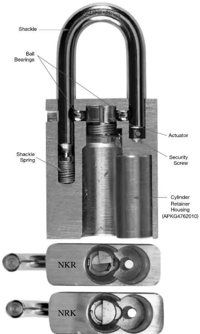
American Lock Series A3600 and A3700
AMERICAN LOCK®
Disassembly
- Unlock shackle
- Use a Phillips screwdriver to remove security screw
- Remove KEY ADVANTAGE cylinder or cylinder and housing
- Remove driver
- Place lock on flat surface and close shackle
- Actuator and ball bearings should fall out, if not, see page 20
- Remove shackle and spring
Assembly
- Insert shackle spring and shackle
- Insert ball bearings
- Insert actuator as shown
- Check operation with follower tool
• Install driver on cylinder - Insert KEY ADVANTAGE cylinder or cylinder and housing
- Insert security screw
- Tighten security screw
- Check operation
text_image
Shackle Ball Bearings Shackle Spring Actuator Security Screw Cylinder Retainer Housing (APKG4762010) NKR NRK| Model | Shackle | Shackle Spring | Actuator | Ball Bearings | Cylinder Housing | |||
| Diameter Length | Part No. | NKR | NRK | |||||
| A3600 5/16" 1-1/8" APKG1582240 APKG1606010 APKG1188280 A36DLRET | APKG1806010 APKG3013010 | |||||||
| A3601 5/16" 2" APKG1582290 APKG1606010 APKG1188280 | A36DLRET APKG1806010 APKG3013010 | |||||||
| A3602 5/16" 3" APKG1582310 APKG1606010 APKG1188280 | A36DLRET APKG1806010 APKG3013010 | |||||||
| A3605 5/16" 5" APKG0000954 APKG1606010 APKG1188280 | A36DLRET APKG1806010 APKG3013010 | |||||||
| A3700 3/8" | 1-1/8" | APKG1581550 | APKG1611010 | APKG1188280 | A36DLRET | APKG1806010 | APKG3013010 | |
| A3701 3/8" 2" | APKG1581570 | APKG1611010 APKG1188280 | A36DLRET | APKG1806010 | APKG3013010 | |||
| A3702 3/8" 3" | APKG1581590 | APKG1611010 APKG1188280 | A36DLRET | APKG1806010 | APKG3013010 | |||
For Quantity Content and Ordering Information, See the Price Book
For Driver Part Numbers, See Page 23
For KEY ADVANTAGE Cylinder Use A, K, S or Y as a Suffix to Indicate Keyway.
For Trap Door Part Numbers, see page 32
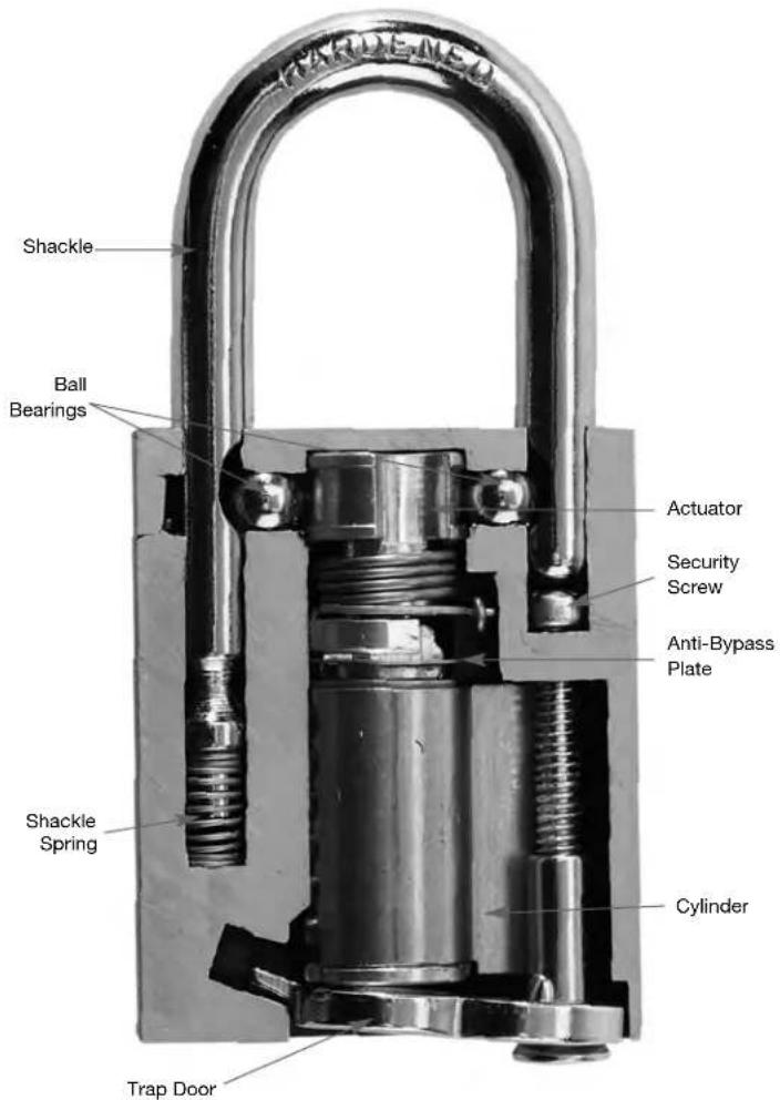
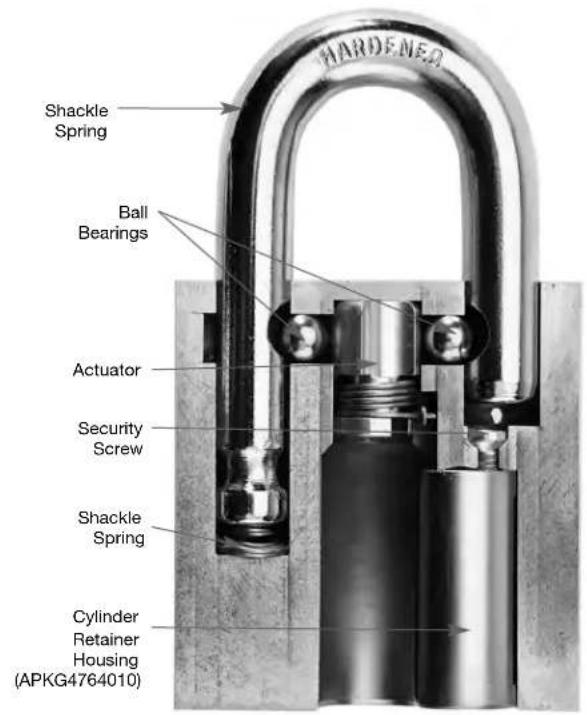
Disassembly
- Unlock shackle
- Use a 1/8" hex wrench to remove security screw
- Remove cylinder and housing
- Remove driver
- Place lock on flat surface and close shackle
- Actuator and ball bearings should fall out, if not, see page 20
- Remove shackle and spring
Assembly
- Insert shackle spring and shackle
- Insert ball bearings
- Insert actuator as shown
- Check operation with follower tool
• Install driver on cylinder - Insert cylinder and housing
- Insert security screw
- Tighten security screw
- Check operation
text_image
HARDENER Shackle Spring Ball Bearings Actuator Security Screw Shackle Spring Cylinder Retainer Housing (APKG4764010)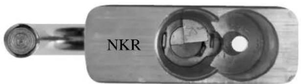
natural_image
Close-up of a metallic mechanical component with circular features and a labeled part 'NKR' (no other text or symbols visible)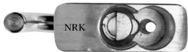
natural_image
Close-up of a metallic mechanical component with circular cutouts and a labeled 'NRK' (no other text or symbols visible)| Model | Shackle | Shackle Spring | Actuator | Ball Bearings | Cylinder Housing | |||
| Diameter Length | Part No. | NKR NRK | ||||||
| A3800 7/16" 1-1/8" APKG | 1582910 | APKG16 | 12010 | APKG1188 | 290 A38DLRET | APKG1807020 | APKG3014020 | |
| A3801 7/16" 2" | APKG1582 | 920 | APKG16120 | 10 | APKG1188290 | A38DLRET | APKG1807020 | APKG3014020 |
For Quantity Content and Ordering Information, See the Price Book
For Driver Part Numbers See Page 23
For KEY ADVANTAGE Cylinder Use A, K, S or Y as a Suffix to Indicate Keyway
For Trap Door Part Numbers, see page 32
Disassembly
- Unlock shackle
- Use control key to remove LFIC
- Remove driver retainer and driver
- Place lock on flat surface and close shackle
- Actuator and ball bearings should fall out, if not, see page 20
- Remove shackle and spring
Assembly
- Insert shackle spring and shackle
- Insert ball bearings
- Insert actuator as shown
- Check operation with follower tool
- Insert driver and driver retainer
- Insert LFIC with control key
- Check operation

text_image
Shackle Ball Bearings Actuator Driver Retainer (APKG3021010) Driver Shackle Spring| Model | Shackle | Shackle Spring | Actuator | Ball Bearings | |||
| Diameter Length | Part No. | NKR NRK | |||||
| A3900S, A3900SWO 3/8" 1-1/8" APKG1581550 | APKG1611010 | APKG1188280 | APKG62081160 | APKG1806010 | |||
| A3901S, A3901SWO 3/8" 2" | APKG1581570 | APKG1611010 | APKG1188280 | APKG62081160 | APKG1806010 | ||
| A3902S, A3902SWO 3/8" 3" | APKG1581590 | APKG1611010 | APKG1188280 | APKG62081160 | APKG1806010 | ||
For Quantity Content and Ordering Information, See the Price Book
Disassembly
- Unlock shackle
- Use a Phillips screwdriver to remove security screw
- Remove security nut and trap door
- Remove cylinder and driver
- Place lock on flat surface and close shackle
- Actuator and ball bearings should fall out, if not, see page 20
- Remove shackle and spring
Assembly
- Insert shackle spring and shackle
- Insert ball bearings
- Insert actuator as shown
- Check operation with follower tool
- Insert cylinder with driver as shown
- Insert trap door
- Insert security nut and screw
- Tighten security screw
- Check operation
text_image
SHRONEED Shackle Ball Bearings Actuator Driver Security Screw Shackle Spring Trap Door Cylinder NKR NRK| Model | Shackle | Shackle Spring | Actuator | Ball Bearings | |||
| Diameter | Length | Part No. | NKR | NRK | |||
| A7200 5/16" 1-1/8" | APKG1582240 | APKG1606010 | APKG1188270 | APKG2081160 | APKG1806010 | ||
| A7201 5/16" 2" | APKG1582290 | APKG1606010 | APKG1188270 | APKG2081160 | APKG1806010 | ||
| A7202 5/16" 3" | APKG1582310 | APKG1606010 | APKG1188270 | APKG2081160 | APKG1806010 | ||
| A7205 5/16" 5" | APKG0000954 | APKG1606010 | APKG1188270 | APKG2081160 | APKG1806010 | ||
| A7260 3/8" 1-1/8" | APKG1581550 | APKG1611010 | APKG1188270 | APKG2081160 | APKG1806010 | ||
| A7261 3/8" | 2" | APKG1581570 | APKG1611010 | APKG1188270 | APKG2081160 | APKG1806010 | |
| A7262 3/8" | 3" | APKG1581590 | APKG1611010 | APKG1188270 | APKG2081160 | APKG1806010 | |
| A7300 7/16" 1-1/8" | APKG1582910 | APKG1612010 | APKG2084100 | APKG2081160 | APKG1807020 | ||
| A7301 7/16" 2" | APKG1582920 | APKG1612010 | APKG2084100 | APKG2081160 | APKG1807020 | ||
For Quantity Content and Ordering Information, See the Price Book For Trap Door Part Numbers see page 32
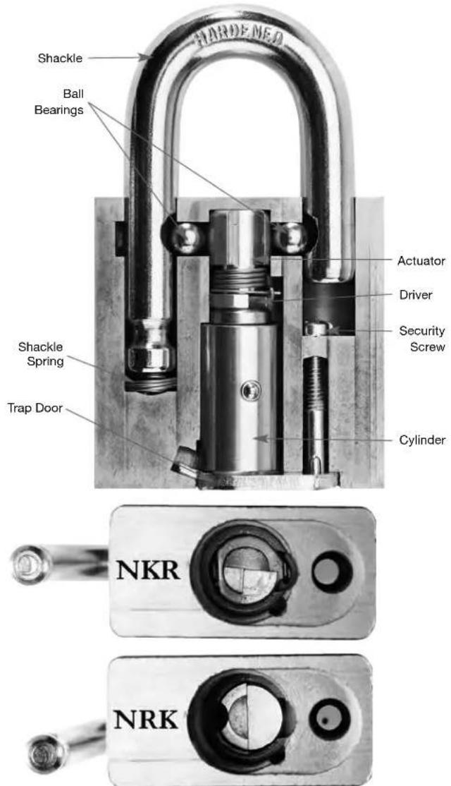
Disassembly
- Unlock shackle
- Use a flat tip screwdriver to remove security screw rap retaining pin from slot
- Remove security nut and trap door
- Remove cylinder plug
- Place lock on flat surface and close shackle
- Actuator and ball bearings should fall out, if not, see page 20
- Remove cylinder retaining pin
- Shackle cannot be removed without drilling pressed retaining pin
Assembly
- Insert shackle spring and shackle if removed
- Insert shackle retaining pins
- Insert ball bearings
- Insert actuator as shown
- Insert cylinder plug and retaining pin
- Insert security screw
- Tighten security screw
- Check operation
text_image
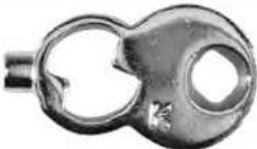
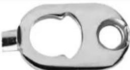
SHARDE-MEN Ball Bearings Shackle Actuator Shackle Spring APKG1601010 Cylinder Plug Retaining Screw (APKG4752010) Retaining Pin (APKG3680030) NKR NRKDisassembly
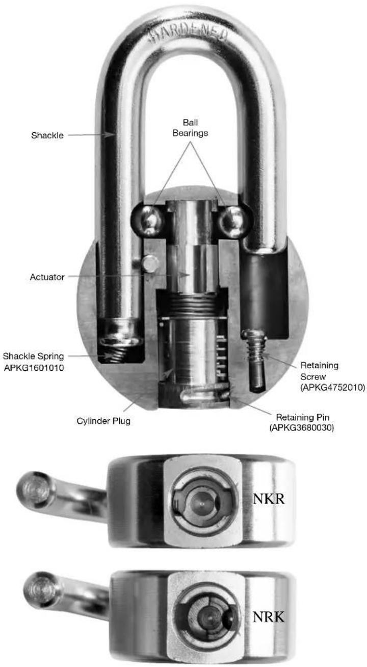
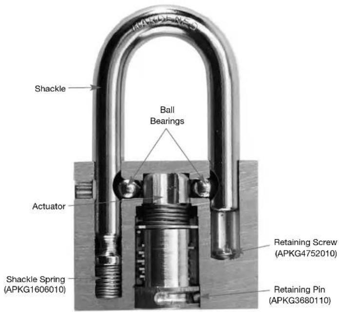
- Unlock shackle
- Use a flat tip screwdriver to remove security screw
- Remove security nut and trap door
- Remove cylinder plug
- Place lock on flat surface and close shackle
- Actuator and ball bearings should fall out, if not, see page 20
- Remove cylinder retaining pin
- Shackle cannot be removed without drilling pressed retaining pin
Assembly
- Insert shackle spring and shackle if removed
- Insert shackle retaining pins
- Insert ball bearings
- Insert actuator as shown
- Check operation with cylinder plug
- Rap retaining pin into place
- Insert security screw
- Tighten security screw
- Check operation
text_image
Shackle Ball Bearings Actuator Shackle Spring (APKG1606010) Retaining Screw (APKG4752010) Retaining Pin (APKG3680110)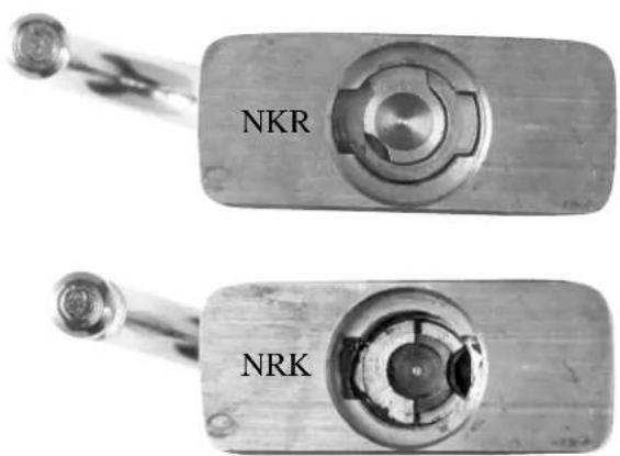
text_image
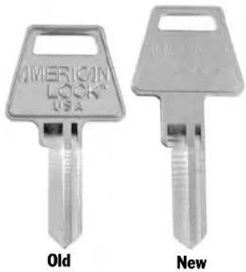
NKR NRKAll padlocks available in the 1000, 5000 and 6000 series bodies, (except 1105, 5530 and 6530), are now available with an environmentally protective cover by adding the modification code COV to the lock part number.
In addition to having the new environmental cover, those locks will have a different shackle with more clearance to allow it to swing free over the cover. You will also notice that as of August, 2006 American Lock keys will have a longer neck for the same reason. The standard keyway will be changed to the longer neck key at that time and other keyways will follow as needed.
natural_image
Two metallic key designs labeled 'Old' and 'New', showing different features (no text or symbols on keys)
natural_image
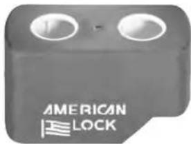
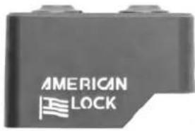
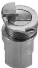
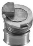
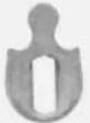
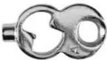
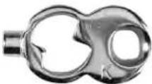
Black and white padlock with metallic handle and 'AMERICAN LOCK' branding (no additional text or symbols visible)These new covers are designed to be fully serviceable. Unlike many other environmental covers for padlocks, these may be removed or even replaced if desired. As you can see here, the cover has two main components, the top and bottom halves. Within each of those halves there are another two components. Each half of the cover is designed to have a comfortable fit to the padlock body that still allows easy removal. In fact easy removal is especially important now that the lock can't effectively be serviced for rekeying without removing at least the bottom half of the cover.
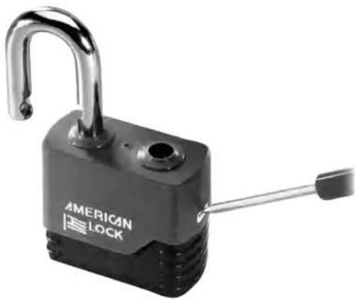
On each side of the cover there is a release vent. Use a small screwdriver to push inward on the high side of the bottom cover while pushing it away from the top cover. Once that side has separated, the other side separates very easily with the screwdriver to allow removal of the bottom cover.
text_image
AMERICAN LOCK

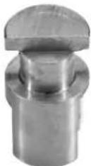
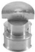
The top half of the cover can typically be pulled up from the padlock body but cannot be removed without disassembly of the lock. There are two grommets in the shackle holes and they are designed to flex during use. This flexible design reduces undue friction against the shackle found in other environmental covers.
natural_image
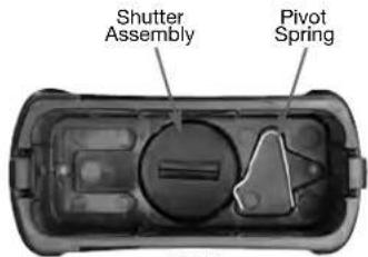
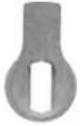
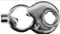
Black padlock with a U-shaped handle and 'AMERICAN LOCK' branding (no additional text or symbols visible)Inside the bottom of the cover you will see the shutter assembly and the pivot spring. The shutter assembly will be held in place by the two tabs shown here and if pried out of place will not likely fly apart. The pivot spring serves as a detent for the shutter assembly and must be removed before the shutter
text_image
Shutter Assembly Pivot SpringSFIC
natural_image
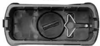
Top-down view of a black plastic container with a circular hole and a triangular handle (no text or symbols)Standard
assembly and installed after. Unless you need to replace the shutter assembly there is no reason to remove it. A different pivot spring is used in each model. On the top at the right is the SFIC version and on the bottom is the standard version.
natural_image
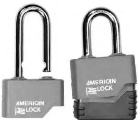
Two gray padlocks with 'AMERICAN LOCK' branding, displayed side by side (no additional text or symbols visible)When replacing or installing the top half of the cover, the lock must be disassembled and the heel side of the shackle should be inserted in the side where the replica American Flag appears. Reassemble the lock and then snap the bottom half into place.
1-3/4"
text_image
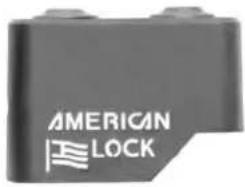
AMERICAN LOCK2"
text_image
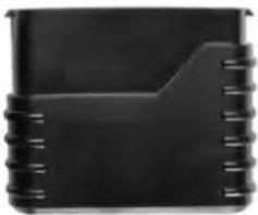
AMERICAN LOCKThis cover is available in two sizes, one for 1-3/4" wide padlock bodies and the other for 2" wide padlock bodies. There are also two different height variations, one for standard padlock cylinders and another for SFIC padlock bodies. That difference is in the bottom half of the cover as you can see here.
natural_image
Black rectangular object with coiled lines and a small protrusion, resembling a device or folder (no visible text or symbols)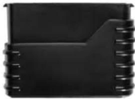
natural_image
Close-up of a black plastic component with coiled spring (no visible text or symbols)SFIC
natural_image
Black rectangular electronic device casing with coiled edges (no visible text or symbols)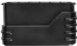
natural_image
Black plastic electronic component with coiled edges (no visible text or symbols)Standard
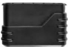
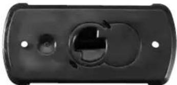
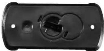
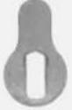
The bottom of the covers does have a design that will help with key orientation. That difference is in the bottom half of the cover as you can see here. The bottom of the covers does have a design that will help with key orientation. The image on the top is the SFIC. The image on the bottom is the standard version.
Retrofitting these covers to an existing lock requires a new longer shackle. Select from the list below.
natural_image
Top-down view of a black plastic electrical connector or bracket (no text or symbols visible)SFIC
natural_image
Black rectangular electronic component with circular and curved slots, no visible text or symbolsStandard
Weatherbuilt™ Component Parts
| Part Description 5/16" Shackle 3/8" Shackle 5/16" Shackle 3/8" Shackle | |||||
| Top Cover Assembly APKG0069402 APKG0069403 APKG0069402 APKG0069403 | |||||
| Bttom Cover Assembly | APKG0069404 APKG0069406 APKG0069405 APKG0069407 | ||||
| Grommet Only | APKG0056292 APKG0056297 APKG0056292 APKG0056297 | ||||
| Shutter Assembly w/Pivot Spring APKG0070456 APKG0070456 APKG0070455 APKG0070455 | |||||
| Pivot Spring Only | APKG0056289 APKG0056289 APKG0068752 APKG0068752 | ||||
| 3/4" | Shackle, Brass | APKG0056792 | N/A | APKG0056792 | N/A |
| 1-1/8" | Shackle, Steel APKG0056291 | APKG0056296 APKG0056291 | APKG0056296 | ||
| 1-1/8" | Shackle, Brass | N/A | APKG0056760 | N/A | APKG0056760 |
| 1-1/8" | Shackle, Stainless | APKG0065435 | APKG0065432 | APKG0065435 | APKG0065432 |
| 2" | Shackle, Steel | APKG006796 | APKG0056761 | APKG0056796 | APKG0056761 |
| 2" | Shackle, Brass | N/A | APKG0056762 | N/A | APKG0056762 |
| 2" | Shackle, Stainless | APKG0065436 | APKG0065433 | APKG0065436 | APKG0065433 |
| 2-1/2" | Shackle, Brass | APKG0056794 | N/A | APKG0056794 | N/A |
| 3" | Shackle, Steel APKG0056797 | APKG0056763 APKG0056797 | APKG0056763 | ||
| 3" | Shackle, Brass | N/A | APKG0056764 | N/A | APKG0056764 |
| 3" | Shackle, Stainless | APKG0065437 | APKG0065434 | APKG0065437 | APKG0065434 |
| 5" | Shackle, Steel | APKG0056798 | N/A | APKG0056798 | N/A |
| 5" | Shackle, Stainless | APKG0065438 | N/A | APKG0065438 | N/A |
Note: Except Grommets and Pivot Springs which have 12 ea. in a package, all other parts above have 6 parts in each package ordered.
American Lock Actuators
| For Lock Series NKR Assembly NRK Assembly Stop Only | |||
| A700 APKG2029010 | APKG2084090 N/A | ||
| A748 APKG1188300 | APKG0000274 N/A | ||
| A780 N/A | APKG0000274 N/A | ||
| A790 N/A | APKG0000275 N/A | ||
| A1405 APKG1188270 | APKG2081160 | APKG2036010 | |
| A1105, A1205, A1305,A5530, A5560, A5570,A5100, A5200, A5260A3105, A3200, A3260,A3560, A3570, A7200,A7260, A5300, A5360 | APKG1188270 | APKG2081160 N/A | |
| A3600, A3700 | APKG1188280 | APKG36DLRET | APKG2036010 |
| A3900 | APKG1188280 | APKG2081160 N/A | |
| A3800 | APKG1188290 | APKG38DLRET | APKG2036010 |
| A7300 | APKG2084100 N/A | N/A | N/A |
| AH10 | APKG1188010 | APKG2083060 N/A | |
| AL50 | APKG1188030 | APKG2083070 N/A | |
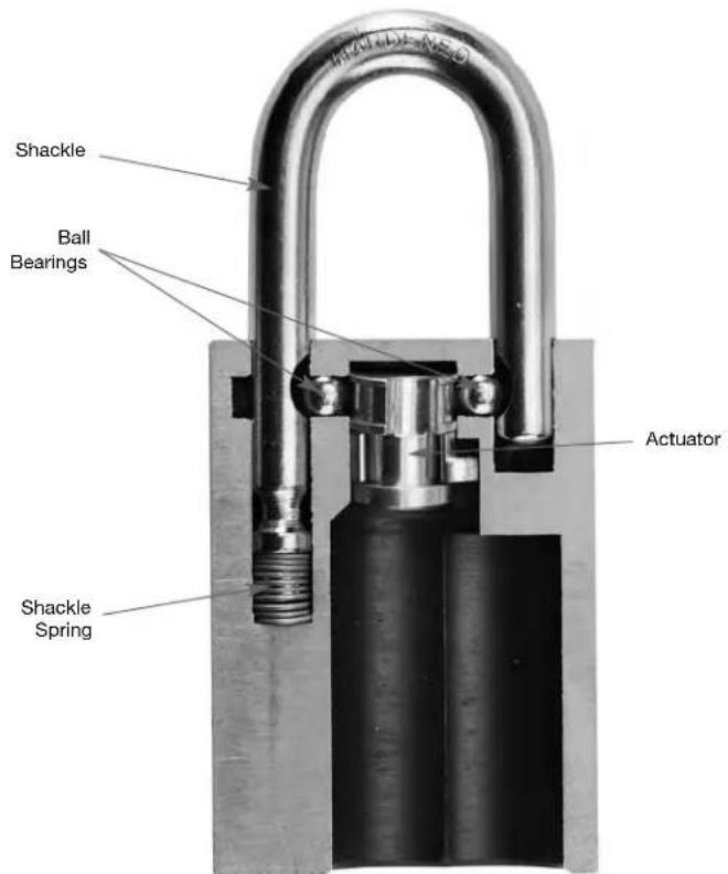
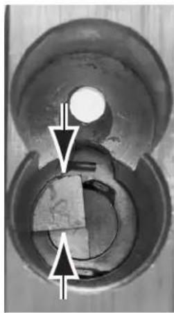
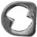
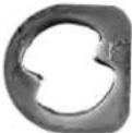
If your American Lock actuator and ball bearings do not fall out when the shackle is pushed back in place use the following procedure.
- Using a following tool, unlock the shackle
- With the actuator in the position shown, grab the pie shaped part using needle nose pliers or a hemostat where shown, DO NOT grab the washer
- Pull actuator from lock body
natural_image
Close-up of a mechanical component with circular features and directional arrows indicating movement or force (no text or symbols)American Lock Actuators (Continued)
AMERICAN LOCK®
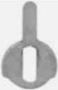
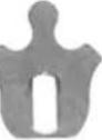
| NKR | 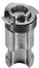 | 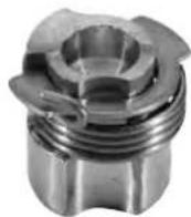 | 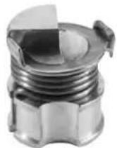 | 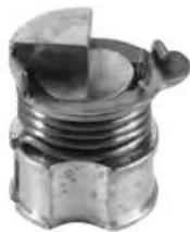 |
| APKG1188010 | APKG1188030 | APKG1188270 | APKG1188280 | |
 |  |  |  | |
| APKG1188290 | APKG1188300 | APKG2029010 | APKG2084100 | |
| NRK | 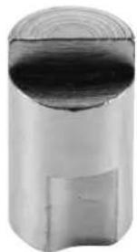 | 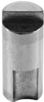 | 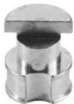 | 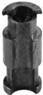 |
| APKG0000274 | APKG0000275 | APKG2081160 | APKG2083060 | |
 |  |  |  | |
| APKG2083070 | APKG2084090 | A36DLRET | A38DLRET |
American Lock Actuators for Master Lock Cylinders
American Lock Cylinders and Master Lock cylinders have a different end configuration and as a consequence require different actuators. The next table indicates which actuator is required to put a Master Lock six pin length cylinder into the American Lock series indicated. Also note that because of the different orientation of the cylinder end, the anti-bypass plate isn't required with the Master Lock cylinders and a 'K' type trap door is also required.
| Actuator | Non Key Retaining (NKR) Non Removable Key (NRK) | |||
 |  |  |  | |
| Lock # | APKG0001666 | APKG0001669 | APKG0001667 | APKG0001670 |
| A700 | X | |||
| A700DL | X | |||
| A1000,A5000,A6000 | X | |||
| A1000DL,A5000DL,A6000DL | X | |||
Date Coding
Most American Lock bodies are stamped with a date code to indicate when the lock body was made. Generally the lock was assembled during the same month. The illustration below shows how to translate this date code. Note that only the first three of four characters stamped on the lock body are part of the date code.
Month
| Jan | Feb | Mar | Apr | May | Jun | Jul | Aug | Sept | Oct | Nov | Dec |
| Z | Y | X | W | V | U | T | S | R | Q | P | O |
Year
| 1 | 2 | 3 | 4 | 5 | 6 | 7 | 8 | 9 | 0 |
| N | M | L | K | J | I | H | G | F | E |
Month Year
X H J x
March 1975
Some cylinders that can be used in American locks do not have a plug end designed to inter face with the American Lock actuator. To overcome that problem an extra part called a driver is needed to adapt the cylinder. The table below specifies the correct driver to be used with different lock body series and different types of cylinders.
| Part Number | Used in Locks | Use Notes | |
 | ADRSCH6 | A3600, A3700, A3800 | Schlage or any 100% copy |
 | ADRMED6 | A3600, A3700, A3800 | Medeco 20 series |
 | ADRLOR30 | A3600, A3700, A3800 | Lori 1530 |
 | ADRLOR39 | A3600, A3700, A3800 | Lori 1539 |
 | ADRVAR36 | A3600, A3700, A3800 | Assortment of Schlage, Medeco and Lori 1539 |
 | APKG0000048 | A3100, A3200, A3500 | Requires SFIC |
 | APKG0001133 | A1405 | Yale 1220 LFIC |
 | APKG3020010 | A3900 | Schlage LFIC |
 | APKG4949200 | A7000 series | Use only HTC2 |
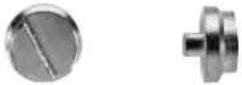
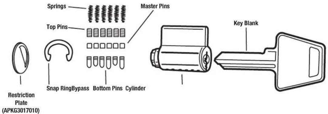
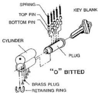
Pin Tumbler Padlock Cylinder
text_image
Restriction Plate (APKG3017010) Springs Top Pins Snap RingBypass Bottom Pins Cylinder Master Pins Key BlankThere is a special cylinder used in the 5200GL. It has 5 pins in it and it is only 5 pins in length, the part number is APTC15.
The cylinder above is the standard pin tumbler padlock cylinder APTC14. When ordered with the part number APTC12 it is supplied with 5 pin tumblers and when ordered as part number APTC14 it will have 6 pin tumblers. Both sizes may be ordered with stainless steel pins by using the part number suffix 'S'. There is a special keyway used in the A748 lock and to get that keyway use part number APTC748 for a 6 pin cylinder. In all cases above, adding the suffix 'KZ' to the part number will get a zero bitted cylinder.
| # Pins Keyway KD Zero Bitted Pins | Stainless Steel | |||
| 5 STD APTC12 | APTC12KZ APTC12S | |||
| 6 STD APTC14 | APTC14KZ APTC14S | |||
| 6 748 | APTC748 APTC748KZ | APTC748 | ||
text_image
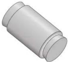
The APT2001 is supplied w removing the roll pin at theServicing the BumpStop® Mechanism
Cylinders containing the BumpStop ^® mechanism pin have one different component than standard cylinders and may be rekeyed when required. That one different component is the BumpStop ^™ top pin. It is longer than a typical top pin and will only let the cylinder operate correctly when it is placed in a correct pin chamber.
natural_image
3D rendered image of a cylindrical mechanical part with flanges (no text or symbols)The table below indicates where the BumpStop ^® pin may be used in the different types of locks. The letter X in the table indicates a cut depth that isn't available in the product or a cut depth that isn't compatible with the BumpStop ^® pin.

text_image
BUMP STOP®When rekeying you need to
figure out which pin chamber has the BumpStop® pin in it and be sure to change where it is for the new combination of the new key.
For example, if you have a cylinder that was keyed to the combination 42645, the BumpStop ^® pin would be in the second pin chamber. If your new key has a combination of 54624, you would need to move the BumpStop ^® pin in the cylinder from the second to the fourth pin chamber.
| Cut # | Master Doorlock | Master Padlock | Padlock KIK | American Padlock |
| 0 | X | X | ||
| 1 | ||||
| 2 | ||||
| 3 | X | X |
Failure to move the pin will certainly make the cylinder vulnerable to a Bump Key attack and may make it impossible to even insert some cut keys because of the extra length of the BumpStop ^® driver pin.
Dump The Bump Pin
A good practice when keying a cylinder with BumpStop® technology is to always dump the Bump Pin. That way when you rekey it you can always put it into a valid location.
For more information on BumpStop ^® , please visit www.bumpstopsecurity.com.
American Lock Interchangeable Cores
The Interchangeable Core cylinders are constructed to the SFIC standards that you encounter with many other brands. Keying uses the same techniques employed for those cylinders.
American Lock offers IC cylinders keyed to existing key systems if you are able to supply the combinations for the operating key, the TMK (Top Master Key), and the Control key. American Lock also has the ability to recreate your entire key system, including all potential expansion, if you can supply bitting combinations of all keys that have been used.
At present, American Lock offers IC cylinders compatible with the A2 and A4 format from the factory. If you are equipped for pinning SFIC cylinders, you can key the cylinders into an existing A3 system without difficulty. The listing below allows construction of a correct SFIC cylinder part number when ordering from Master Lock.
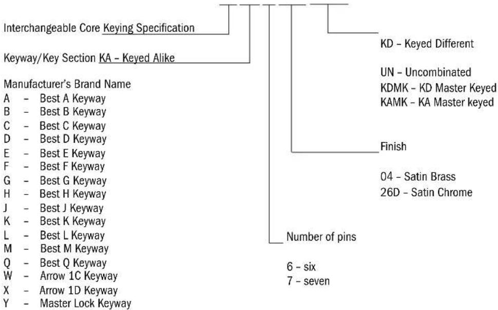
ORDERING INFORMATION
Interchangeable Cores
ACA604KD
flowchart
graph TD
    A["Interchangeable Core Keying Specification"] --> B["Keyway/Key Section KA - Keyed Alike"]
    B --> C["Manufacturer's Brand Name"]
    C --> D["A - Best A Keyway"]
    C --> E["B - Best B Keyway"]
    C --> F["C - Best C Keyway"]
    C --> G["D - Best D Keyway"]
    C --> H["E - Best E Keyway"]
    C --> I["F - Best F Keyway"]
    C --> J["G - Best G Keyway"]
    C --> K["H - Best H Keyway"]
    C --> L["J - Best J Keyway"]
    C --> M["K - Best K Keyway"]
    C --> N["L - Best L Keyway"]
    C --> O["M - Best M Keyway"]
    C --> P["Q - Best Q Keyway"]
    C --> Q["W - Arrow 1C Keyway"]
    C --> R["X - Arrow 1D Keyway"]
    C --> S["Y - Master Lock Keyway"]
    B --> T["KD - Keyed Different"]
    B --> U["UN - Uncombined"]
    B --> V["KDMK - KD Master Keyed"]
    B --> W["KAMK - KA Master keyed"]
    B --> X["Finish"]
    X --> Y["04 - Satin Brass"]
    X --> Z["26D - Satin Chrome"]
    B --> AA["Number of pins"]
    AA --> AB["6 - six"]
    AA --> AC["7 - seven"]
American Lock Door Hardware Multi-Cylinders
Two different types of cylinders can be used in the 3600, 3700 and 3800 series locks to make them compatible with Door Hardware keys. The first type is our Key Advantage cylinder. It is a cylinder with a figure 8 shell but it is
not an Interchangeable Core. Three different keyways are available and may be specified to be supplied with the padlock body by adding a single letter suffix to the part number. Those are;
A3600K = Kwikset standard keyway
A3600S = Schlage C standard keyway
A3600Y = Yale standard E1R (8) keyway
Rekeying of these cylinders must be accomplished with a follower as they are blind drilled and the holes are plugged at the bottom of the keyway. These cylinders are available
5-pin zero-bitted with 6-pin capacity.
text_image
SPRING TOP PIN BOTTOM PIN Cylinder PLUG "O" BITTED BRASS PLUG RETAINING RING KEY BLANKAmerican Lock Edge™ Key Control Cylinders
Something new in the rim, mortise and cylindrical product is the patent-pending key control keyways. They are available for the rim, mortise and KIK cylinder types. The virtual keyway must be specified when ordering. The diagram below may be used to configure a part number from all of the different options.
ORDERING INFORMATION
Rim, Mortise and Cylindrical
flowchart
graph TD
    A["American Lock Indicator"] --> B["Cylinder Type"]
    B --> C["Length of Mortise 100=1" Length"]
    B --> D["Length of Rlm 112=1-1/8" Length"]
    B --> E["Key-In-Knob Cylinders 200=Lori 1539 Compatible"]
    F["Cylinder Type"] --> G["D=Key-in-Knob"]
    F --> H["M=Mortise"]
    F --> I["R=Rim"]
    J["Pin WP4=4 Pin WP6=6 Pin"] --> K["Finish 03 = Bright Brass\n26D = Satin Chrome\n10B* = Satin Bronze,\nDark Oxidized\nOil Rubbed\n*(Rim & Mortise Only)"]
    L["Keying Options"] --> M["UN=Uncombined"]
    L --> N["KD=Keyed Different"]
    L --> O["KA=Keyed Alike"]
    L --> P["MK=Keyed Different, Master Keyed"]
    L --> Q["KAMK=Keyed Alike, Master Keyed"]
    R["Mortise Cams"] --> S["AR1=Adams Rite® MS"]
    R --> T["YS1=Yale® Large"]
    R --> U["RC3=Corbin Russwin® Cloverleaf"]
    R --> V["FS1=Falcon® Standard"]
    R --> W["SS1=Schlage® Standard"]
    R --> X["YS2=Yale® Standard"]
    R --> Y["Rim Tailpiece"]
    Y --> Z["FTP=Fixed Tailpiece"]
    Y --> AA["LTP=Lazy Tailpiece"]
text_image
Set Screw Tumbler Springs Top Pins Anti-Drill Pins Master Pins Bottom Pins Mortise Plug with Anti-Drill Pins Screw Cam Trim Ring Mortise Shell with Anti-Drill Pins Ball BearingsThese key control cylinders are known as the Edge ^™ mechanism and require a Master Lock 291 pinning kit to service. That kit has spare ball bearings in it along with the stainless steel springs required for the Edge ^™ products. (The springs in the American Lock pinning kit have not been tested to BHMA standards in this product.)
The Edge™ system rim, mortise and KIK cylinders have the same .397" plug diameter found in the Master padlock cylinders, but the plug heads and shell OD have been enlarged to match traditional door hardware cylinder sizes. Because of the potential to interfere with the ball bearing mechanism, the mortise cylinder uses a single screw to mount the cam. There are six different cams available for the mortise lock and different tailpieces for the rim and KIK. (see table, page 28)
American Lock Edge™ System Master Keying
The Edge™ System products require application of one important rule regarding key system development. Number one master pins cannot be used in any Edgecylinder. Those cylinders each have two slots in the shell for the ball bearings and if a number one master pin in the plug falls into one of those slots it will jam the cylinder preventing further rotation of the plug or withdrawal of the key.
If you do not have the capability to produce keying systems that have eliminated the need for number one master pins, American Lock will generate a system for you with up to four levels of keying and a total of 20,000 CK's in the system for a six pin cylinder. American Lock has a flat fee for this service but you must realize that a copy of the key system will not be retained by American Lock. A pinning matrix is also supplied with the keying system on a CD_ROM.
American Lock KIK Cylinders
We are now are offering KIK cylinders with a wide range of keyways. Our part numbering system for these products can be found below. Please consult the American Lock Price Book (A-001) for available pin options by cylinder.
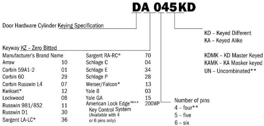
ORDERING INFORMATION
KIK Cylinders
The diagram below may be used to configure a KIK part number for all of the different options.
other
DA 045KD | Keyway KZ - Zero Bitted | Manufacturer's Brand Name | Sargent RA-RC* | 70 | |---|---|---|---| | Arrow | 10 | Schlage C | 04 | | Corbin 59A1-2 | 01 | Schlage E | 34 | | Corbin 60 | 29 | Schlage P | 28 | | Corbin Russwin L4 | 07 | Weiser/Falcon* | 13 | | Kwikset* | 12 | Yale 8 | 03 | | Lockwood | 08 | Yale GA | 15 | | Russwin 981/852 | 11 | American Lock Edge™** | 200WP | | Russwin D1 | 30 | Key Control System (Available with 4 or 6 pins only) | 4 - four** 5 - five 6 - six | Door Hardware Cylinder Keying Specification Number of pins* Indicates a composite keyway
** Exclusively available for Edge™ Key Control System only
The door hardware cylinders are rekeyable using standard .115" diameter pins. The plug is mounted to the shell with a ring retainer, and use of a follower is recommended for rekeying. In order to mount the cylinders in the lock, a cylinder retainer plug is placed over the bible of the cylinder. The retainer plug has a threaded hole used to mount it to the lock via the toe side shackle hole and the socket screw. This cylinder also requires a special driver to be placed between the cylinder tail and the lock actuator in order to function.
American Lock Cylinders (Continued)
AMERICAN LOCK®
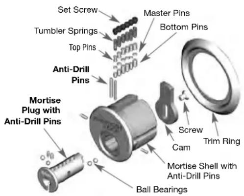
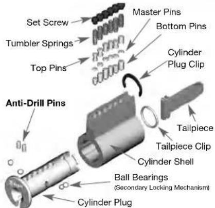
Door Hardware Component Parts
All door hardware compatible plugs have hardened inserts to protect the shear line from drilling. The mortise and rim shells also have hardened inserts to protect the shear line and mounting points and were subjected to and passed the UL437 test for drilling. They also have set screws to cap the pin chambers for comb attack resistance.
Rekeying may be accomplished by removing the set screws at the top of each pin chamber or with the use of an American Lock Edge™ follower (APKG0060612) and standard rekeying techniques. See the Catalog for further model and pricing information.
text_image
Set Screw Tumbler Springs Top Pins Anti-Drill Pins Master Pins Bottom Pins Cylinder Plug Clip Tailpiece Tailpiece Clip Cylinder Shell Ball Bearings (Secondary Locking Mechanism) Cylinder PlugComponent Parts
| EdgeTM Rim and Mortise | Standard Rim and Mortise | ||||||
| Part Number | Quantity in Package | Cylinder Component Code | Part Number | Quantity in Package | Cylinder Component Code | ||
 | APKG0049804 | 10 AR1 |  | APKG1270960 | 10 AR1 | ||
 | APKG1270970 | 10 AR4 | |||||
 | APKG0049806 | 10 FS1 | 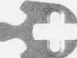 | APKG1270980 | 10 RC3 | ||
 | APKG0049805 | 10 RC3 | 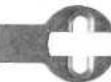 | APKG1270950 | 10 YS2 | ||
 | APKG0049807 | 10 SS1 |  | APKG1270820 | 10 RT1 | ||
 | APKG0049967 | 10 N/A | |||||
 | APKG0049809 | 10 YS1 |  | APKG0049968 | 10 N/A | ||
 | APKG0049808 | 10 YS2 |  | APKG0049971 | 10 N/A | ||
 | APKG0056303 | 10 N/A | |||||
| ### | APKG0049969 | 10 FTP |  | APKG0049966 | 10 N/A | ||
| ### | APKG0049970 | 10 LTP |  | APKG0056302 | 10 N/A | ||
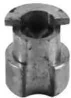
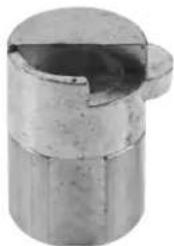
Tubular Key Padlock Cylinders
1-Housing
2 - Knurled Pin
3 - Key Pins
4 - P | u g
5 - Shell
6 - Driver Pins
7 - Driver Springs
8 - Stop Spacer (APKG1228010)
text_image
Housing Knurled Pin Key Pins Plug Shell Driver Pins Driver Springs Stop Spacer (APKG1228010)The AHTC2 is for use in the A7000 series tubular padlocks only. But may be KA with the A8000 series cam lock shown below.
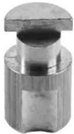
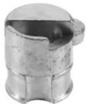
Tubular Key Cam Lock Cylinders
1-Housing
2 - Knurled Pin
3 - Key Pins
4 - Plug
5-Shell
6 - Driver Pins
7 - Driver Springs
8 - Stop Spacer
9 - Stop Plate
10 - Cam
11 - Lock Washer (APKG1232010)
12 - Nut (APKG1234010)
text_image
- Housing - Knurled Pin - Key Pins - Plug - Shell - Driver Pins - Driver Springs 8 - Stop Spacer 9 - Stop Plate 10 - Cam 11 - Lock Washer (APKG1232010) 12 - Nut (APKG1234010)Tubular cylinder assembly places the plug inside the shell and then that sub assembly is placed inside the housing. The housing and shell have a receptacle for a knurled pin to be pressed into place. In the padlock cylinder that pin protrudes and acts as a locator for the cylinder in the padlock body. In the cam lock it is below the threads so it doesn't interfere with the mounting nut. This pin is hardened and should never be removed.
The knurled Stop spacer in both locks is pressed into place in the end of the housing and requires a puller to be used to disassemble the cylinder for rekeying.
Tubular Servicing
To use the ATRT-1 puller;
- Drill 2 holes with a 5/64" diameter. They should be 1/16" to 3/32" deep as shown above.
- Retract the center screw of the puller and place tool over the back of the lock.
- Thread both side screws into the holes drilled into the stop spacer. Use a hex wrench and turn each screw at least 3 turns into the drilled holes.
- Tighten the center screw until the stop spacer has been pulled from the housing.
- Remove the tool from the stop spacer and the spacer may be reused by pressing it back into the housing.
An extra shell is supplied in the keying kit to assist in loading pins and springs. If the extra shell is placed on the plug shaft and aligned with each pin chamber it is much easier to load new tumbler pins and springs. Once the new pins and springs have been loaded, remove the extra shell and insert the knurled stop spacer into the housing.
Tumbler pins for tubular cylinders have a .078"/.079" diameter. The Key Pins come in seven different lengths and each length must be used with a specific sized Driver Pin to prevent crushing springs in the cylinder. See chart at Right.
text_image
5/64" Drill Two Places 13 32 ATRT-1| KEY PIN DRIVER PIN | |
| Size Length | Size Length |
| 1 .2035" 5 .200" | → |
| 2 .2190" 5 .200" | → |
| 3 .2345" 4 .185" | → |
| 4 .2500 3 .170" | → |
| 5 .2655" 2 .155" | → |
| 6 .2810" 1 .140" | → |
| 7 .2965" 1 .140" | → |
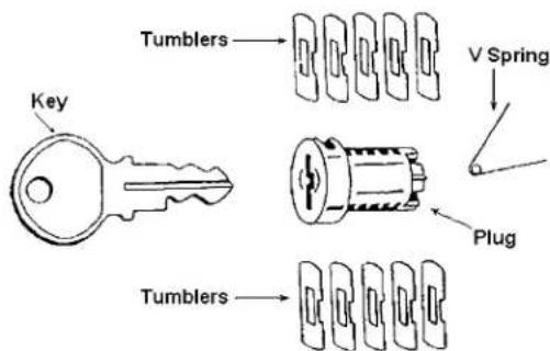
Disc Tumbler Cylinder Plug
The disc tumbler padlock uses a double bitted waveform key. While it is possible to rekey a disc tumbler plug with the parts included in the service kit we recommend ordering keyed plugs from the factory by code.
If you do want to attempt rekeying, follow this process;
- Remove existing V-spring and tumblers.
- Insert new tumblers, (5 sets of 2 each), and V-spring.
- Insert new operating key, being sure it is fully inserted.
- Using a hole saw, file or grinder, remove excess material from disc tumblers until they are flush with the outside diameter of the plug. Be sure not to change the shape or diameter of the plug during this process.
Replacement cylinders may be ordered with two different keying specifications, Coded and Uncoded. If you want coded plugs order the correct keyway and specify the code that should operate if you want a particular key, otherwise just use these part numbers;
Coded - ABTC1A, ABTC1B, ABTC1C, ABTC1E
Uncoded - ABTC1KZA, ABTC1KZB, ABTC1KZC, ABTC1KZE
text_image
Tumblers Key V Spring Plug TumblersAmerican Lock Retainers & Trap Doors
The trap door is an essential element in providing security for the cylinder in your American lock. The orientation of the trap door is slightly different based upon the keyway in the cylinder. The table below indicates the part number of the trap door that should be used in a lock when a particular keyway is used in that same lock. The picture in the table is how the trap door would appear from the bottom of the lock.
| Picture Used on | Locks with Keyways Part Number | ||
 | All models requiring a trap door except those listed in the table below | STD, R1, R2 | APKG4680210 |
| Stainless SteelAll models requiring a trap door except those listed in the table below | STD, R1, R2 APKG0110026 | ||
 | All models requiring a trap door except those listed in the table below | R7, R8, MLCKeywaysand ALC Edge" | APKG4680220 |
| Stainless SteelAll models requiring a trap door except those listed in the table below | R7, R8, MLCKeywaysand ALC Edge" | APKGOP10774 | |
 | A700 STD, R1, R2 APKG4680200 | ||
 | A700 | R7, R8, MLC Keywaysand ALC Edge" | APKG4680230 |
 | A748, A780, A790 748, STD, R1, R2 | APKG4680260 | |
 | A748, A780, A790 | R7, R8, MLC Keywaysand ALC Edge" | APKG4680270 |
 | All 7000 Series All APKG4680240 | ||
 | All Except 3000 Series All APKG4761010 | ||
| Stainless Steel - All Except 3000 Series All APKG0110028 | |||
 | All Except 3000 Series All APKG4746010 | ||
| Stainless Steel - All Except 3000 Series All APKG0110027 |
American Lock Keys & Keyways
AMERICAN LOCK®
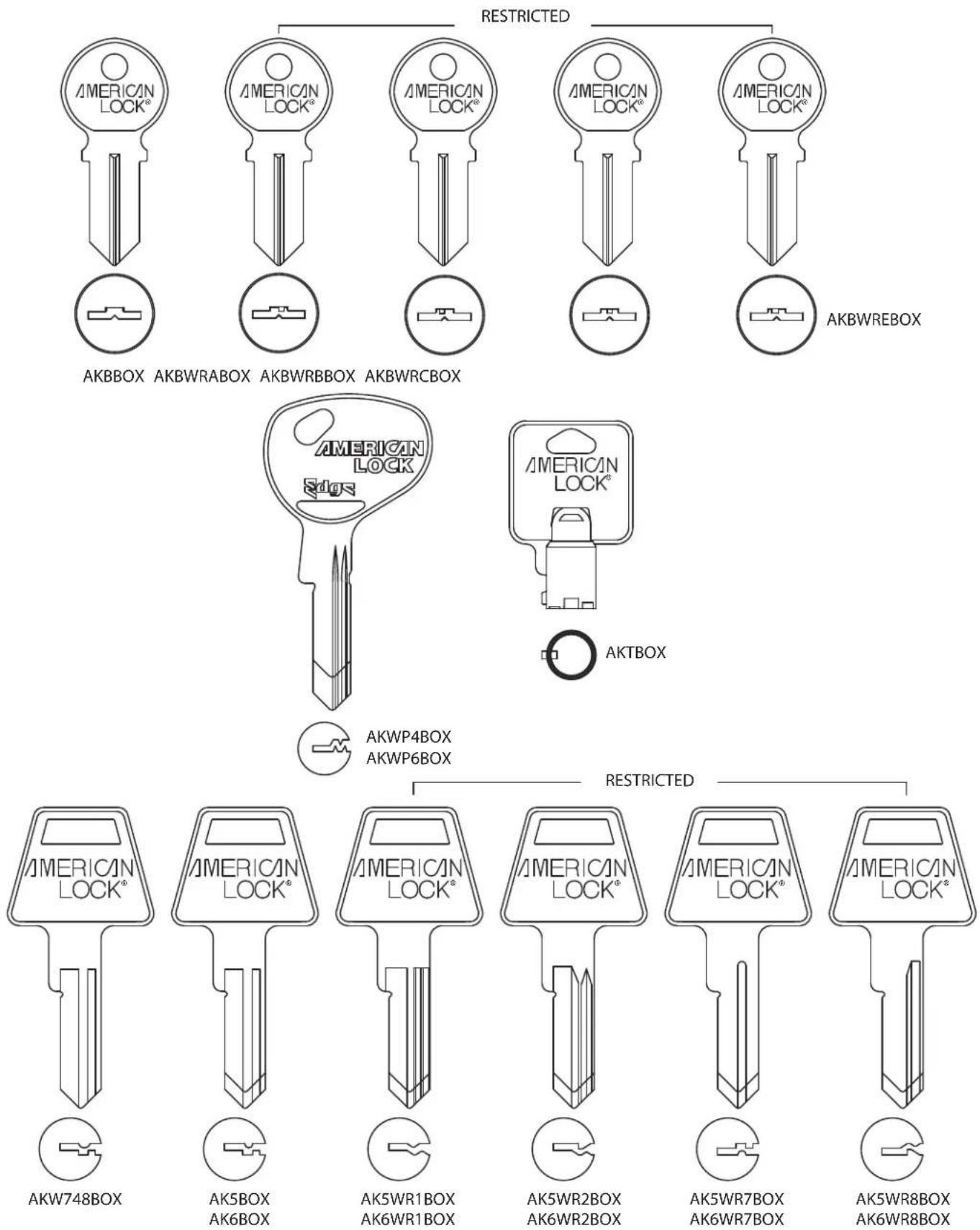
text_image
RESTRICTED AMERICAN LOCK® AKBBOX AKBWRABOX AKBWRBBOX AKBWRCBOX AMERICAN LOCK® AKBWRREBOX AMERICAN LOCK® AKTBOX AMERICAN LOCK® AKWP4BOX AKWP6BOX RESTRICTED AMERICAN LOCK® AKW748BOX AK5BOX AK6BOX AK5WR1BOX AK6WR1BOX AMERICAN LOCK® AK5WR2BOX AK6WR2BOX AMERICAN LOCK® AK5WR7BOX AK6WR7BOX AMERICAN LOCK® AK5WR8BOX AK6WR8BOXAmerican Lock Bitting Specifications
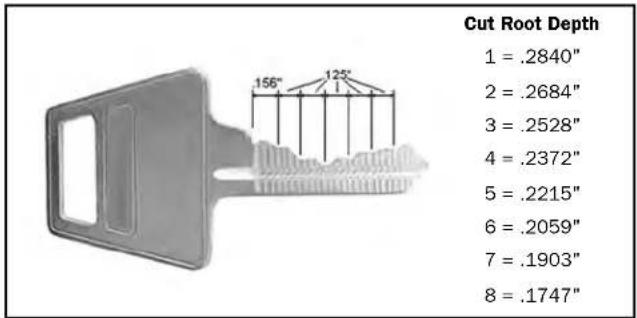
All American Lock keys use the same spacing and depth specifications as shown here.
other
| Cut Root Depth | | --------------- | | 1 | | 2 | | 3 | | 4 | | 5 | | 6 | | 7 | | 8 |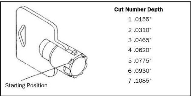
text_image
Cut Number Depth 1 .0155" 2 .0310" 3 .0465" 4 .0620" 5 .0775" 6 .0930" 7 .1085" Starting PositionSpacing: 1st cut center = .156" - Center to center = .125"
Lock Lubricants
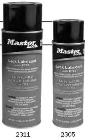
Master Lock Lock Lubricant can be used for lubricating the various lock components. The lubricants contain PTFE formulations that can be used for padlocks, door locks, automotive, marine, and multipurpose applications. The effective operating temperature range is -40°F to 500°F and helps de-ice pre-lubricated locks.
Two aerosol sizes are available that contain a "dry" lubricant formula that lubricates without collecting dirt or dust. The 2305 aerosol is a 5.25 oz. size convenient for carrying to jobs and the 2311 aerosol is an 11 oz. size ideal for keeping in the shop.
text_image
Master Lock Lock Lubricant 2311 Lubricante 2305 WATERMELLOPE 2305 WATERMELLOPE 2305 WATERMELLOPE 2305 WATERMELLOPE 2305 WATERMELLOPE 2305 WATERMELLOPE 2305 WATERMELLOPE 2305 WATERMELLOPE 2305 WATERMELLOPE 2311 Master Lock Lock Lubricant 2305 Lubricante 2305 WATERMELLOPE 2305 WATERMELLOPE 2305 WATERMELLOPE 2305 WATERMELLOPE 2305Recommended Padlock Cleaning & Lubrication
Over time, dust particles and chemicals in the air settle on and in the padlock. They can then create friction inside the precision locking and keying components and impede the opening and closing of the padlock. Annual cleaning is recommended. In particularly dusty or corrosive environments, clean every three months.
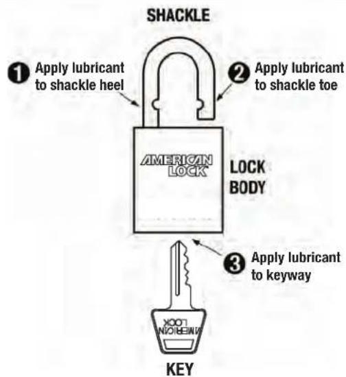
Recommended Directions:
- Flush grease and dirt from the padlock as needed.
- Apply Master Lock ^ Lock Lubricant to the keyway and shackle holes, using a very light spray. "Psst", not "Pssssssssssssssssst"!
- Insert key, open and close padlock several times to distribute lubricant.
text_image
SHACKLE ① Apply lubricant to shackle heel ② Apply lubricant to shackle toe AMERICAN LOCK LOCK BODY KEY ③ Apply lubricant to keyway| Average number of times opened per day | Dry Lubricant Application Schedule (Normal Environment) |
| Once per year1 to 5 | |
| Twice per year51 to |
text_image
Scanned image of a printed document with visible text and a small inset image showing a logo or watermark.APK-1 Pin Kit
100 ea. Bottom pins 1 through 8
100 ea. Top pins
10 ea. Driver springs
5 ea. Security screws
5 ea. Security nuts
natural_image
Illustration of an electronic device with a transparent housing and internal components (no visible text or symbols)ATCR3 Tubular Keying Kit
100 ea. Key pins
100 ea. Driver pins
100 ea. Springs
10 ea. 180° Stop plates
10 ea. 90° Stop plates
1 ea. Shell
1 ea. ATRT-1 rekeying tool
1 ea. Depth key
text_image
AMERICAN LOCKASK-8 Pin Kit
100 ea. Bottom pins 1 through 8
100 ea. Master pins 2 through 7
100 ea. Top pins
100 ea. Driver springs
12 ea. (Small) A5000 series ball bearings
12 ea. (Large) A700 series ball bearings
25 ea. Security screws
25 ea. Security nuts
2 ea. Trap doors for A700 series locks
4 ea. Trap doors for A5000 series locks
1 ea. American Lock Co. 6 pin cylinder
2 ea. Actuators for A700 series locks
4 ea. Actuators for A5000 series locks
1 ea. American Lock Co. 5 pin cylinder
10 ea. Snap rings
1 ea. Follower tool
text_image
Scanned document page with Chinese text and a small illustration of mechanical components or parts.AALSK-18 Disc Tumbler Service Kit
25 ea. AL50 cylinder retaining pins
25 ea. AH10 cylinder retaining pins
25 ea. Cylinder Retaining screws
10 ea. AL50 shackle springs
10 ea. AH10 shackle springs
100 ea. Brass disc tumblers
10 ea. Tumbler V-springs
10 ea. Ball bearings, AL50 small size
10 ea. Ball bearings, AH10 large size
10 ea. AH10 knurled shackle pins
10 ea. AH10 retaining shackle pins
3 ea. Cylinder assemblies w/2 keys ea.
3 ea. AH10 Actuators
3 ea. AL50 Actuators
For Quantity Content and Ordering Information See the Price Book

AMERICAN LOCK
The Locksmith's Lock.
American Lock Company, a Division of Master Lock Company LLC 137 W. Forest Hill Ave., Milwaukee, WI 53154 U.S.A. | 800-323-456 © 2013 Master Lock Company LLC | All Rights Reserved