CE-H22F14-S1 - Multiprise AV Siig - Free user manual and instructions
Find the device manual for free CE-H22F14-S1 Siig in PDF.

| Product Type | AV Power Strip / Surge Protector |
| Number of Outlets | 14 (8 spaced, 6 standard) |
| Surge Protection Rating | 3920 Joules |
| Maximum Electrical Rating | 15A, 125V, 1875W |
| USB Charging | 2 USB-A ports (2.4A total) |
| Power Cord Length | 6 ft (1.8 m) |
| Dimensions (L x W x H) | 18.5 x 4.5 x 2.2 inches |
| Weight | 2.2 lbs (1 kg) |
| Indicator Lights | Protected, Grounding, and Surge Status LEDs |
| Switch | Master on/off switch with built-in circuit breaker |
| Mounting | Keyhole slots for wall or desk mounting |
| Clamping Voltage | 330V (L-N, L-G, N-G) |
| Response Time | Less than 1 nanosecond |
| EMI/RFI Filtering | 150 dB attenuation |
| Safety Certifications | UL 1449 3rd Edition, cUL, TUV |
| Operating Temperature | 32°F to 104°F (0°C to 40°C) |
| Material | High-impact ABS plastic, flame retardant |
| Warranty | Limited Lifetime Warranty |
| Connected Equipment Guarantee | $200,000 |
| Cleaning Instructions | Unplug and wipe with a dry cloth; do not use liquids |
| Spare Parts Availability | Contact SIIG support for replacement cords or units |
| Repairability | Non-repairable; replace unit if damaged |
Frequently Asked Questions - CE-H22F14-S1 Siig
User questions about CE-H22F14-S1 Siig
0 question about this device. Answer the ones you know or ask your own.
Ask a new question about this device
Download the instructions for your Multiprise AV in PDF format for free! Find your manual CE-H22F14-S1 - Siig and take your electronic device back in hand. On this page are published all the documents necessary for the use of your device. CE-H22F14-S1 by Siig.
USER MANUAL CE-H22F14-S1 Siig
natural_image
Simple circular icon with a horizontal line inside, no text or symbols present.HDMI HDBaseT Extender with IR/RS-232 Control and PoE -100m
User Reference Guide
Introduction
The HDMI HDBaseT Extender with IR/RS-232 Control and PoE - 100m extends HDMI signals up to 100 meter through a single Cat5e/6 cable, and also carries additional signals including 100BaseT Ethernet, bi-directional IR, RS-232 and PoE.
Key Features and Benefits
- Delivers high-quality HDMI video/audio in 1080p resolution up to 100m and 4Kx2K format with 7.1-channel sound up to 70m
-
HDBaseT technology transmitts HDMI signal, 100BaseT Ethernet, bi-directional IR, RS-232 and PoE (Power over Ethernet) over a single CAT5/6 cable
-
PoE feature allows one power adapter to power both transmitter and receiver units
- Included mounting kit enables you to easily mount the units in place
• Cooling slots drastically improve heat dissipation for dependable performance and long life
Package Contents
• HDMI HDBaseT Extender with IR/RS-232 Control and PoE - 100m (TX & RX)
- IR blaster extension cable (x2)
- IR receiver extension cable (x2)
- Phoenix contact (x2)
- Power adapter
- Mounting kit
- User reference guide
Layout
text_image
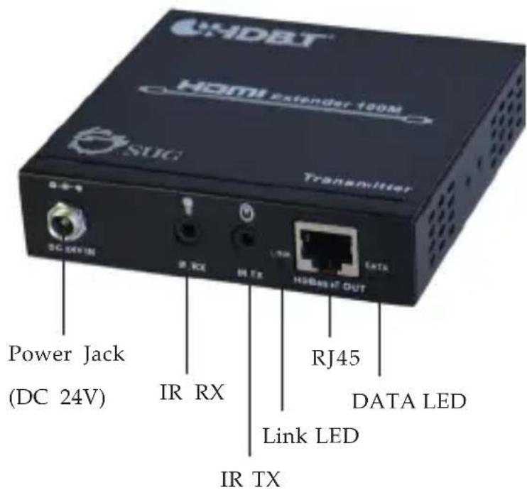
CHDET HDMI Extender 190M SUG Transmitter SC 24V IN IR RX IR TX HSB487 OUT Power Jack (DC 24V) RJ45 DATA LED Link LED IR TXFigure 1: Transmitter - front side
• Power Jack (DC 24V): Connects to the included power adapter
- IR RX: Infrared 3.5mm socket. Plug IR _Receiver extension cable here
- IR TX: Infrared 3.5mm socket. Plug IR Blaster extension cable here
- Link LED: Indicates the status of TX and RX connection
- ON: Good connection
- Flashing: Weak connection
-OFF: No connection
-
RJ45 (HDBaseT Out): Linked to the RJ45 of the Receiver via a Cat5e/6 cable
• DATA LED: Indicates the status of HDMI source -
ON: HDMI signal with HDCP
- Flashing: HDMI signal without HDCP
-OFF: No HDMI signal detected
text_image
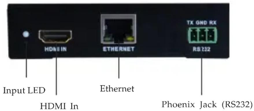
Input LED HDMI In Ethernet ETHERNET TX GND RX RS232 Phoenix Jack (RS232)Figure 2: Transmitter - rear side
- Input LED: On when HDMI source detected
- HDMI In: Connects to your HDMI source with an HDMI cable (cable not included)
- Ethernet: Connect your Ethernet cable here to establish an extended network connection
- Phoenix Jack (RS232): Connects to the included Phoenix contact and RS-232 connector (not included), then connect to a serial port device or computer for data transferring
text_image
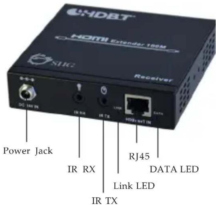
DHDBT HDMI Extender 180M SVC Receiver DG 14V IN IR RX IR TX LTRR HDBT+T IN DATA Power Jack IR RX RJ45 DATA LED Link LED IR TXFigure 3: Receiver -front side
• Power Jack (DC 24V): Connects to the included power adapter
- IR RX: Infrared 3.5mm socket. Plug IR _Receiver extension cable here
- IR TX: Infrared 3.5mm socket. Plug IR Blaster extension cable here
- Link LED: Indicates the connecting status of TX and RX
- ON: Good connection
- Flashing: Weak connection
-OFF: No connection
- RJ45 (HDBaseT IN): Linked to the RJ45 of the Transmitter via a Cat5e/6 cable
- DATA LED: Indicates the status of HDMI source
- ON: HDMI signal with HDCP
- Flashing: HDMI signal without HDCP
-OFF: No HDMI signal detected
text_image
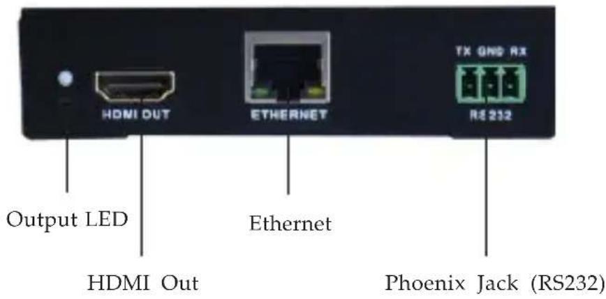
Output LED HDMI Out ETHERNET TX GND RX R2 212 Ethernet Phoenix Jack (RS232)Figure 4: Receiver - rear side
• Output LED: On when the HDMI signal is detected
- HDMI Out: Connects to your HDMI display with an HDMI cable (cable not included)
- Ethernet: Connect your Ethernet cable here to establish an extended network connection
- Phoenix Jack (RS232): Connects to the included Phoenix contact and RS-232 connector (not included), then connect to a serial port device or computer for data transferring
* Phoenix Jack wire connection:
- Insert the included Phoenix contact to Phoenix Jack.
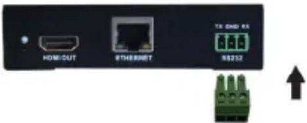
text_image
HOME/CUT Ethernet TX GND RX 88252Figure 5
- Connect the wires (not included) to the included Phoenix contact and the RS232 connector as below diagram.
- Via pin to pin (Parallel) connector or cable:

text_image
RX GND TX 1 2 3 2 RXD 3 TXD 5 GNDFigure 6
- Via null connector or cable:

text_image
RX GND TX 1 2 RXD 2 TXD 3 5 GNDFigure 7
IR Extension Cables
* IR Blaster cable (optional):
Connect the IR blaster cable to your HDMI Extender's (Transmitter and Receiver) IR TX connector to send out IR command signals, if needed.

natural_image
Black cable with connectors and a small connector, isolated on white background (no text or symbols)Figure 8
* IR Receiver cable (optional):
Connect the IR receiver cable to your HDMI Extender's (Transmitter and Receiver) IR RX connector to receive IR command signals, if needed.

natural_image
Black cable with attached audio jack and connector, isolated on white background (no text or symbols)Figure 9
Hardware Installation
Thanks to PoE technology, only one power adapter is needed to power both the Transmitter and Receiver.
- Power off all devices, including the HDMI device (source) and display.
- Connect your HDMI source (such as a Blu-ray player) to the transmitter's HDMI IN connector by HDMI cable (not included).
- Connect your HDMI display (such as a LCD TV) to the receiver's HDMI OUT connector by HDMI cable (not included).
- Optional: Connect the included Phoenix contact to Phoenix Jack of TX / RX and RS-232 connector (not included), then connect the serial port devices to the Transmitter and Receiver.
-
Optional: Connect Ethernet connector on the Transmitter / Receiver to a router or switch for Ethernet network, and connect the Receiver/Transmitter to your computer by using an Ethernet cable (not included).
-
Optional: Connect the IR extension cables to IR TX and IRRX connector on the Transmitter and Receiver.
- Connect your CAT5e/6 LAN cable between RJ45 connector of the Transmitter and Receiver.
- Plug the included power adapter into the Power Jack of either the Transmitter or Receiver, then plug it into reliable power source.
- Power on the HDMI device (source) and display, then the HDMI extender is ready for use.
* PoE (Power over Ethernet)
- Connect one power adapter to TX or RX, and the power will pass through
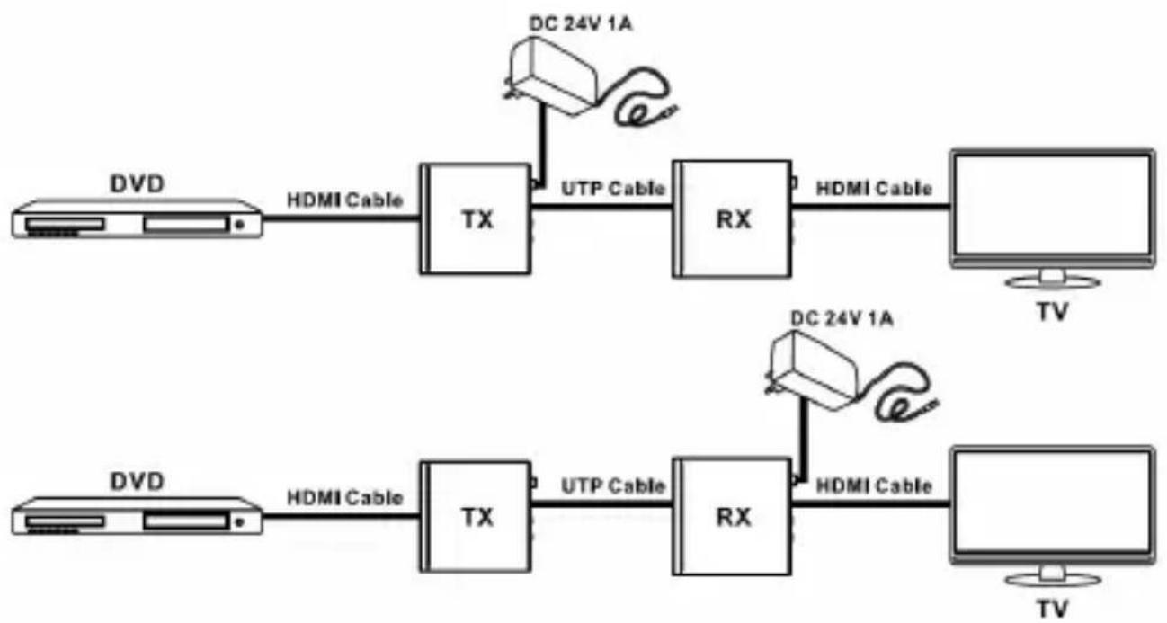
flowchart
graph LR
    A["HDVI"] -->|HDMI Cable| B["TX"]
    B -->|UTP Cable| C["RX"]
    C -->|HDMI Cable| D["TV"]
    E["HDVI"] -->|HDMI Cable| F["TX"]
    F -->|UTP Cable| G["RX"]
    G -->|HDMI Cable| H["TV"]
    I["DC 24V 1A"] --> J["Device"]
    K["DC 24V 1A"] --> L["Device"]
Figure 10
* Bidirectional Infrared control
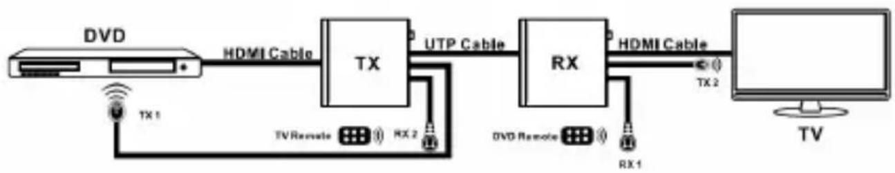
flowchart
graph LR
    A["Monitor"] -->|TX 1| B["+"]
    B --> C["TX"]
    C -->|UTP Cable| D["RX"]
    D -->|HDMI Cable| E["+"]
    E --> F["TV"]
    C --> G["TV Remote"]
    D --> H["+"]
    H --> I["+"]
    I --> J["+"]
    J --> K["+"]
    K --> L["+"]
    L --> M["+"]
    M --> N["+"]
    N --> O["+"]
    O --> P["+"]
    P --> Q["+"]
    Q --> R["+"]
    R --> S["+"]
    S --> T["+"]
    T --> U["+"]
    U --> V["+"]
    V --> W["+"]
    W --> X["+"]
    X --> Y["+"]
    Y --> Z["+"]
    Z --> AA["+"]
    AA --> AB["+"]
    AB --> AC["+"]
    AC --> AD["+"]
    AD --> AE["+"]
    AE --> AF["+"]
    AF --> AG["+"]
    AG --> AH["+"]
    AH --> AI["+"]
    AI --> AJ["+"]
    AJ --> AK["+"]
    AK --> AL["+"]
    AL --> AM["+"]
    AM --> AN["+"]
    AN --> AO["+"]
    AO --> AP["+"]
    AP --> AQ["+"]
    AQ --> AR["+"]
    AR --> AS["+"]
    AS --> AT["+"]
    AT --> AU["+"]
    AU --> AV["+"]
    AV --> AW["+"]
    AW --> AX["+"]
    AX --> AY["+"]
Figure 11
* Bidirectional RS232 control

flowchart
graph LR
    subgraph Top_1
        A["PC"] -->|Rs232 Cable| B["TX"]
        B -->|UTP Cable| C["RX"]
        C -->|Rs232 Cable| D["TV"]
        C -->|Rs232 Cable| E["PC"]
    end
    subgraph Bottom_1
        F["PC"] -->|Rs232 Cable| G["TX"]
        G -->|UTP Cable| H["RX"]
        H -->|Rs232 Cable| I["TV"]
        H -->|Rs232 Cable| J["PC"]
    end
    Top_1 -->|RS-232 Equipped HDMI Matrix| H
    Top_1 -->|RS-232 Equipped HDMI Matrix| G
    Top_1 -->|RS-232 Equipped HDMI Matrix| F
Figure 12
* Bidirectional Ethernet signal
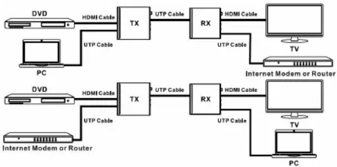
flowchart
graph LR
    subgraph Top
        A["PC"] -->|HDMI Cable| B["TX"]
        B -->|UTP Cable| C["RX"]
        C -->|HDMI Cable| D["TV"]
        C -->|UTP Cable| E["Internet Modem or Router"]
    end
    subgraph Bottom
        F["PC"] -->|HDMI Cable| G["TX"]
        G -->|UTP Cable| H["RX"]
        H -->|HDMI Cable| I["TV"]
        H -->|UTP Cable| J["Internet Modem or Router"]
    end
Figure 13
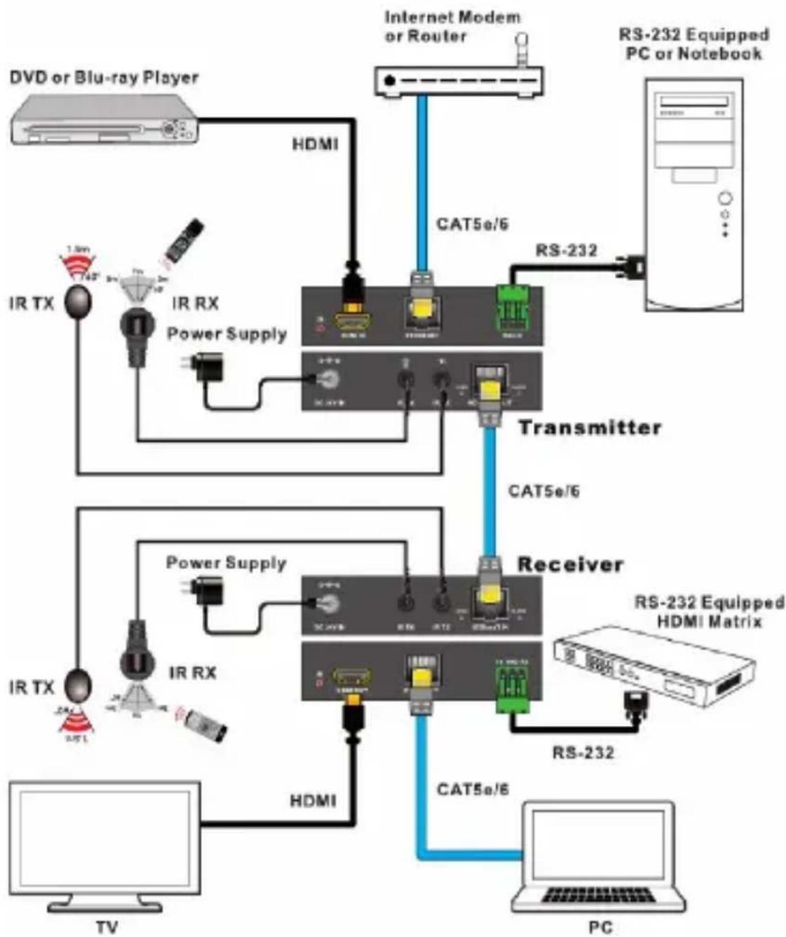
Application
HDMI HDBaseT Extender with IR/RS-232 Control and PoE - 100m extends HDMI signals up to 100m, and also supports 100BaseT Ethernet, bi-directional IR, RS232 and PoE.
flowchart
graph TD
    A[" DVD or Blu-ray Player "] --> B[" HDMI "]
    B --> C[" Internet Modem or Router "]
    C --> D[" RS-232 Equipped PC or Notebook "]
    D --> E[" Transmitter "]
    E --> F[" Receiver "]
    F --> G[" RTX "]
    F --> H[" IR RX "]
    F --> I[" Power Supply "]
    F --> J[" HDMI "]
    F --> K[" TV "]
    F --> L[" PC "]
    M[" IR TX "] --> N[" Power Supply "]
    O[" IR RX "] --> P[" Power Supply "]
    Q[" Power Supply "] --> R[" Power Supply "]
    S[" Radio"] --> T[" Radio "]
    U[" Radio"] --> V[" Radio "]
    W[" Radio"] --> X[" Radio "]
    Y[" Radio"] --> Z[" Radio "]
    AA[" Radio"] --> AB[" Radio "]
    AC[" Radio"] --> AD[" Radio "]
    AE[" Radio"] --> AF[" Radio "]
    AG[" Radio"] --> AH[" Radio "]
    AI[" Radio"] --> AJ[" Radio "]
    AK[" Radio"] --> AL[" Radio "]
    AM[" Radio"] --> AN[" Radio "]
    AO[" Radio"] --> AP[" Radio "]
    AQ[" Radio"] --> AR[" Radio "]
    AS[" Radio"] --> AT[" Radio "]
    AU[" Radio"] --> AV[" Radio "]
    AW[" Radio"] --> AX[" Radio "]
    AY[" Internet Modem or Router "] --> AZ[" CAT5e/6 "]
    AZ --> BA[" RS-232 Equipped HDMI Matrix "]
    BA --> BB[" RS-232 Equipped PC or Notebook "]
Figure 14: Application
Blank Page
Technical Support and Warranty
QUESTIONS? SIIG's Online Support has answers! Simply visit our web site at www.siig.com and click Support. Our online support database is updated daily with new drivers and solutions. Answers to your questions could be just a few clicks away. You can also submit questions online and a technical support analyst will promptly respond.
SIIG offers a 1-year manufacturer warranty with this product. This warranty covers the original purchaser and guarantees the product to be free of any defects in materials or workmanship for one (1) year from the date of purchase of the product. This warranty is not transferable and is available only to the original purchaser of the product.
SIIG will, at our discretion, repair or replace (with an identical product or product having similar features and functionality) the product if defective in materials or workmanship. This warranty gives you specific legal rights, and you may also have other rights which vary from state to state. Please see our web site for more warranty details.
If you encounter any problems with this product, please follow the procedures below.
A) If it is within the store's return policy period, please return the product to the store where you purchased from.
B) If your purchase has passed the store's return policy period, please follow the steps below to have the product repaired or replaced.
Step 1: Submit your RMA request.
Go to www.siig.com, click Support, then REQUEST A PRODUCT REPLACEMENT to submit a request to SIIG RMA or fax a request to 510-657-5962. Your RMA request will be processed, if the product is determined to be defective, an RMA number will be issued.
Step 2: After obtaining an RMA number, ship the product.
- Properly pack the product for shipping. All accessories that came with the original package must be included
- Include a copy of your original sales receipt inside the package with date of purchase and place of purchase circled and clearly visible
- Clearly write your RMA number on the top of the returned package. SIIG will refuse to accept any shipping package, and will not be responsible for a product returned without an RMA number posted on the outside of the shipping carton
- You are responsible for the cost of shipping to SIIG. Ship the product to the following address:
SIIG, Inc. 6078 Stewart Avenue Fremont, CA 94538-3152, USA RMA #: ____
• SIIG will ship the repaired or replaced product via Ground in the U.S. and International Economy outside of the U.S. at no cost to the customer
Founded in 1985, SIIG, Inc. is a leading manufacturer of IT connectivity solutions (including Serial ATA and Ultra ATA Controllers, FireWire, USB, and legacy I/O adapters) that bridge the connection between Desktop/Notebook systems and external peripherals. SIIG continues to grow by adding A/V and Digital Signage connectivity solutions to our extensive portfolio.
SIIG products offer comprehensive user manuals, many user-friendly features, and are backed by an extensive manufacturer warranty. High quality control standards are evident by the overall ease of installation and compatibility of our products, as well as one of the lowest defective return rates in the industry. SIIG products can be found in computer retail stores, mail order catalogs, through major distributors, system integrators, VARs and through e-commerce sites.
PRODUCT NAME
HDMI HDBaseT Extender with IR/RS-232 Control and POE - 100m
FCC RULES: TESTED TO COMPLY WITH FCC PART 15, CLASS B
OPERATING ENVIRONMENT: FOR HOME OR OFFICE USE
FCC COMPLIANCE STATEMENT:
This device complies with part 15 of the FCC Rules. Operation is subject to the following two conditions: (1) This device may not cause harmful interference, and (2) this device must accept any interference received, including interference that may cause undesired operation.
THE PARTY RESPONSIBLE FOR PRODUCT COMPLIANCE
SIIG, Inc.
6078 Stewart Avenue
Fremont, CA 94538-3152, USA
Phone: 510-657-8688
HDMI HDBaseT Extender with IR/RS-232 Control and POE - 100m is a trademark of SIIG, Inc. SIIG and the SIIG logo are registered trademarks of SIIG, Inc. All other names used in this publication are for identification only and may be trademarks of their respective owners.